Embed Size (px)
Citation preview

8/12/2019 Optical Fiber-Dispersion Sp 2014
http://slidepdf.com/reader/full/optical-fiber-dispersion-sp-2014 1/19
Dispersion in Optical Fiber
1. Light Pulse Dispersion and the Reasons
In digital communication systems, information is encoded in the form of pulses and then theselight pulses are transmitted from the transmitter to the receiver. The larger the number of pulses
that can be sent per unit time and still be resolvable at the receiver end, the larger is the capacity
of the system.
However, when the light pulses travel down the fiber, the pulses spread out, and this
phenomenon is called Pulse Dispersion. Pulse dispersion is shown in the following figure.
Pulse dispersion is one of the two most important factors that limit a fiber’s capacity (the other is
fiber’s losses). Pulse dispersion happens because of four main reasons:
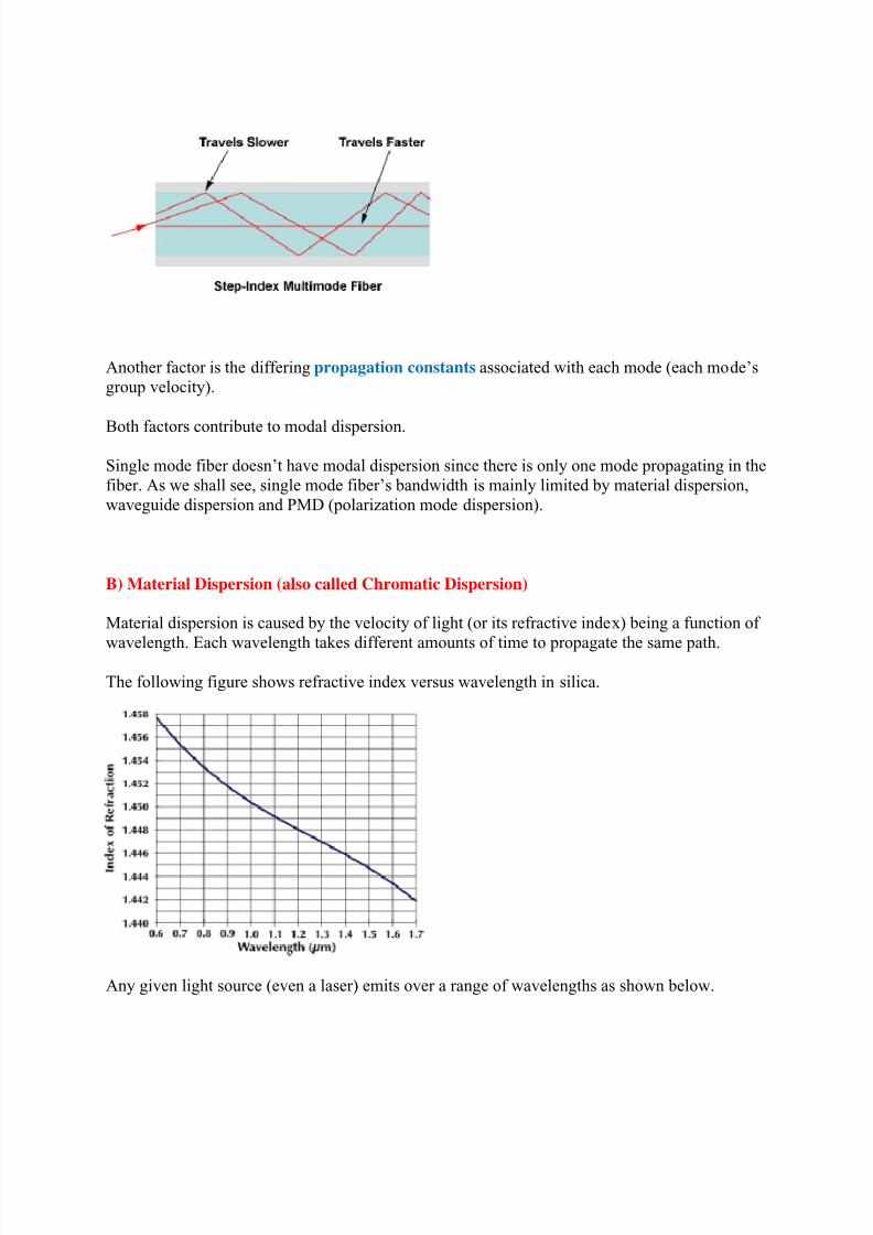
A) Intermodal Dispersion (also called Modal Dispersion or Group Delay)
Modal dispersion is only important in multimode fibers.
Many different modes propagate in a multimode fiber. Each of these modes takes a different path
and thus different length when traveling down the fiber.
8/12/2019 Optical Fiber-Dispersion Sp 2014
http://slidepdf.com/reader/full/optical-fiber-dispersion-sp-2014 2/19
Another factor is the differing propagation constants associated with each mode (each mode’s
group velocity).
Both factors contribute to modal dispersion.
Single mode fiber doesn’t have modal dispersion since there is only one mode propagating in the
fiber. As we shall see, single mode fiber’s bandwidth is mainly limited by material dispersion,
waveguide dispersion and PMD (polarization mode dispersion).
B) Material Dispersion (also called Chromatic Dispersion)
Material dispersion is caused by the velocity of light (or its refractive index) being a function of
wavelength. Each wavelength takes different amounts of time to propagate the same path.
The following figure shows refractive index versus wavelength in silica.
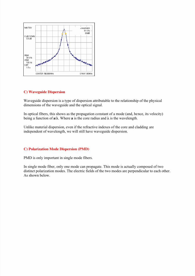
Any given light source (even a laser) emits over a range of wavelengths as shown below.
8/12/2019 Optical Fiber-Dispersion Sp 2014
http://slidepdf.com/reader/full/optical-fiber-dispersion-sp-2014 3/19
C) Waveguide Dispersion
Waveguide dispersion is a type of dispersion attributable to the relationship of the physical
dimensions of the waveguide and the optical signal.
In optical fibers, this shows as the propagation constant of a mode (and, hence, its velocity) being a function of a/λ . Where a is the core radius and λ is the wavelength.
Unlike material dispersion, even if the refractive indexes of the core and cladding areindependent of wavelength, we will still have waveguide dispersion.
C) Polarization Mode Dispersion (PMD)
PMD is only important in single mode fibers.
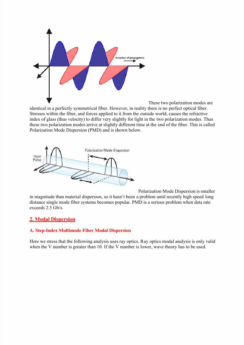
In single mode fiber, only one mode can propagate. This mode is actually composed of two
distinct polarization modes. The electric fields of the two modes are perpendicular to each other.
As shown below.
8/12/2019 Optical Fiber-Dispersion Sp 2014
http://slidepdf.com/reader/full/optical-fiber-dispersion-sp-2014 4/19
These two polarization modes are
identical in a perfectly symmetrical fiber. However, in reality there is no perfect optical fiber.Stresses within the fiber, and forces applied to it from the outside world, causes the refractive
index of glass (thus velocity) to differ very slightly for light in the two polarization modes. Thusthese two polarization modes arrive at slightly different time at the end of the fiber. This is calledPolarization Mode Dispersion (PMD) and is shown below.
Polarization Mode Dispersion is smaller
in magnitude than material dispersion, so it hasn’t been a problem until recently high speed long
distance single mode fiber systems becomes popular. PMD is a serious problem when data rate
exceeds 2.5 Gb/s.
2. Modal Dispersion
A. Step-Index Multimode Fiber Modal Dispersion
Here we stress that the following analysis uses ray optics. Ray optics modal analysis is only validwhen the V number is greater than 10. If the V number is lower, wave theory has to be used.
8/12/2019 Optical Fiber-Dispersion Sp 2014
http://slidepdf.com/reader/full/optical-fiber-dispersion-sp-2014 5/19
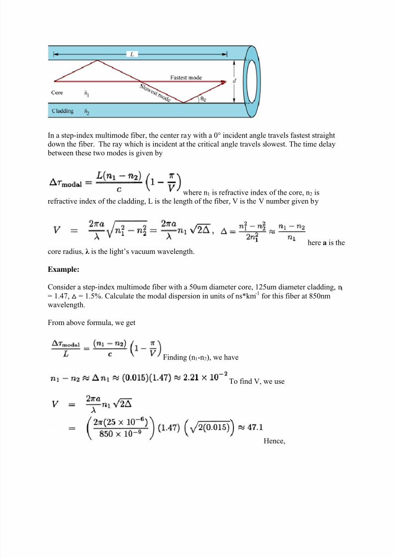
In a step-index multimode fiber, the center ray with a 0° incident angle travels fastest straightdown the fiber. The ray which is incident at the critical angle travels slowest. The time delay
between these two modes is given by
where n1 is refractive index of the core, n2 isrefractive index of the cladding, L is the length of the fiber, V is the V number given by
here a is the
core radius, λ is the light’s vacuum wavelength.
Example:
Consider a step-index multimode fiber with a 50um diameter core, 125um diameter cladding, n1
= 1.47, △ = 1.5%. Calculate the modal dispersion in units of ns*km-1 for this fiber at 850nmwavelength.
From above formula, we get
Finding (n1-n2), we have
To find V, we use
Hence,
8/12/2019 Optical Fiber-Dispersion Sp 2014
http://slidepdf.com/reader/full/optical-fiber-dispersion-sp-2014 6/19
8/12/2019 Optical Fiber-Dispersion Sp 2014
http://slidepdf.com/reader/full/optical-fiber-dispersion-sp-2014 7/19
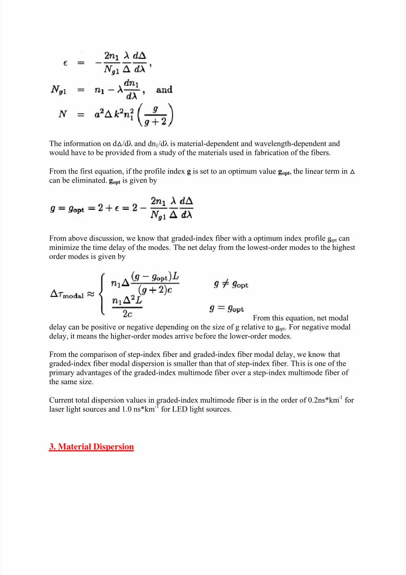
The information on d △/dλ and dn1/dλ is material-dependent and wavelength-dependent andwould have to be provided from a study of the materials used in fabrication of the fibers.
From the first equation, if the profile index g is set to an optimum value gopt, the linear term in △ can be eliminated. gopt is given by
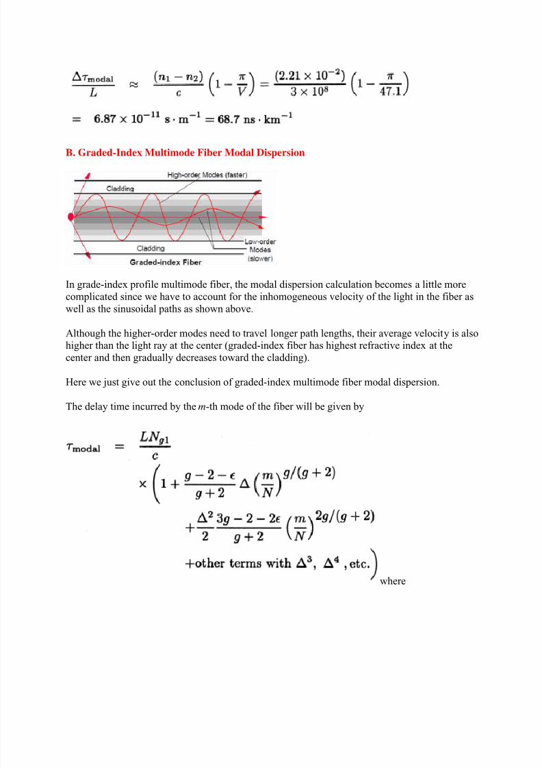
From above discussion, we know that graded-index fiber with a optimum index profile gopt can
minimize the time delay of the modes. The net delay from the lowest-order modes to the highestorder modes is given by
From this equation, net modaldelay can be positive or negative depending on the size of g relative to gopt. For negative modal
delay, it means the higher-order modes arrive before the lower-order modes.
From the comparison of step-index fiber and graded-index fiber modal delay, we know that
graded-index fiber modal dispersion is smaller than that of step-index fiber. This is one of the
primary advantages of the graded-index multimode fiber over a step-index multimode fiber ofthe same size.
Current total dispersion values in graded-index multimode fiber is in the order of 0.2ns*km
-1
forlaser light sources and 1.0 ns*km-1
for LED light sources.
3. Material Dispersion
8/12/2019 Optical Fiber-Dispersion Sp 2014
http://slidepdf.com/reader/full/optical-fiber-dispersion-sp-2014 8/19
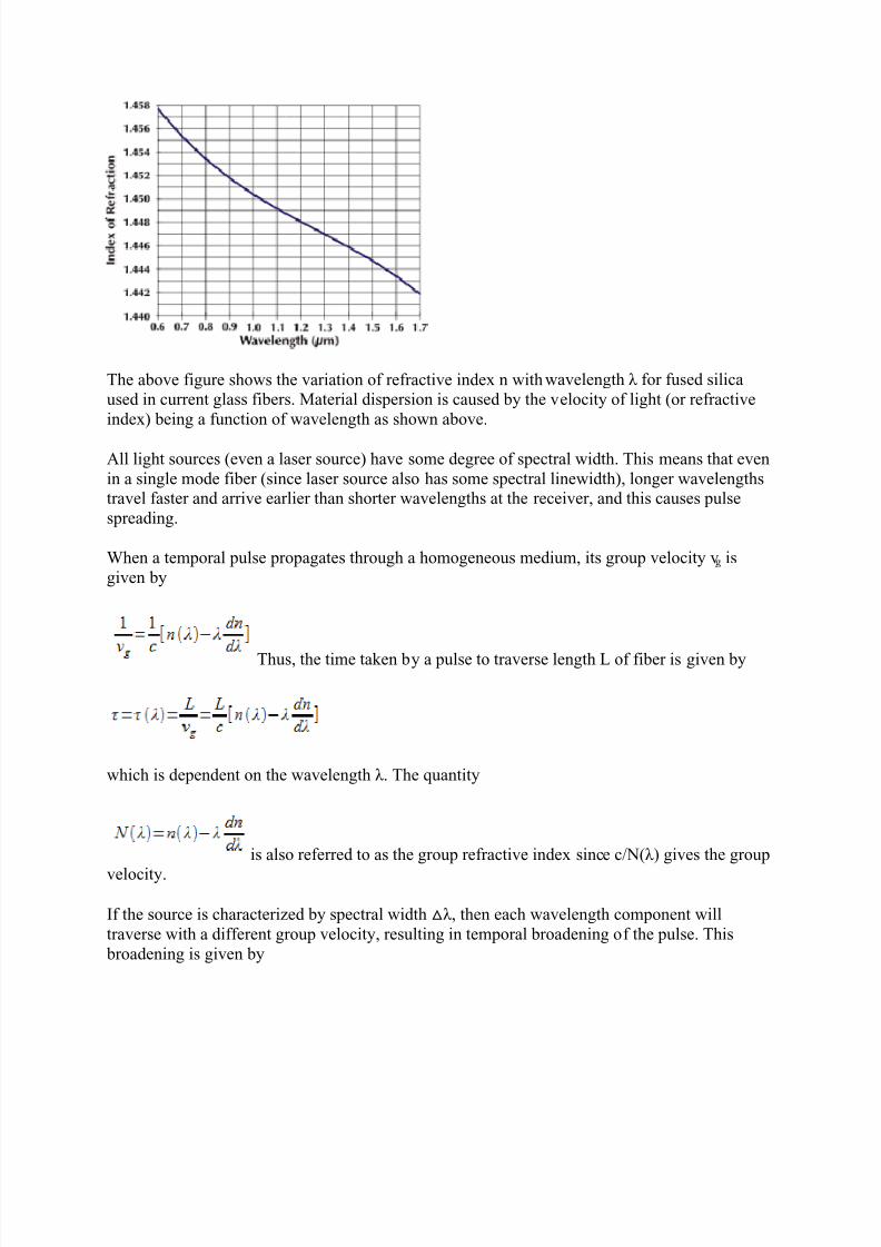
The above figure shows the variation of refractive index n with wavelength λ for fused silica
used in current glass fibers. Material dispersion is caused by the velocity of light (or refractive
index) being a function of wavelength as shown above.
All light sources (even a laser source) have some degree of spectral width. This means that even
in a single mode fiber (since laser source also has some spectral linewidth), longer wavelengthstravel faster and arrive earlier than shorter wavelengths at the receiver, and this causes pulse
spreading.
When a temporal pulse propagates through a homogeneous medium, its group velocity vg is
given by
Thus, the time taken by a pulse to traverse length L of fiber is given by
which is dependent on the wavelength λ. The quantity
is also referred to as the group refractive index since c/N(λ) gives the group
velocity.
If the source is characterized by spectral width △λ, then each wavelength component will
traverse with a different group velocity, resulting in temporal broadening of the pulse. This
broadening is given by
8/12/2019 Optical Fiber-Dispersion Sp 2014
http://slidepdf.com/reader/full/optical-fiber-dispersion-sp-2014 9/19
The quantity (λ 2d
2n/dλ
2) is a dimensionless quantity. The above
pulse broadening is referred to as material dispersion and occurs when a pulse propagatesthrough any dispersive medium.
Material dispersion Dm is usually specified in units of picoseconds per kilometer (fiber length) per nanometer (spectral width of the source) as given by
where λ is in micrometers (um).
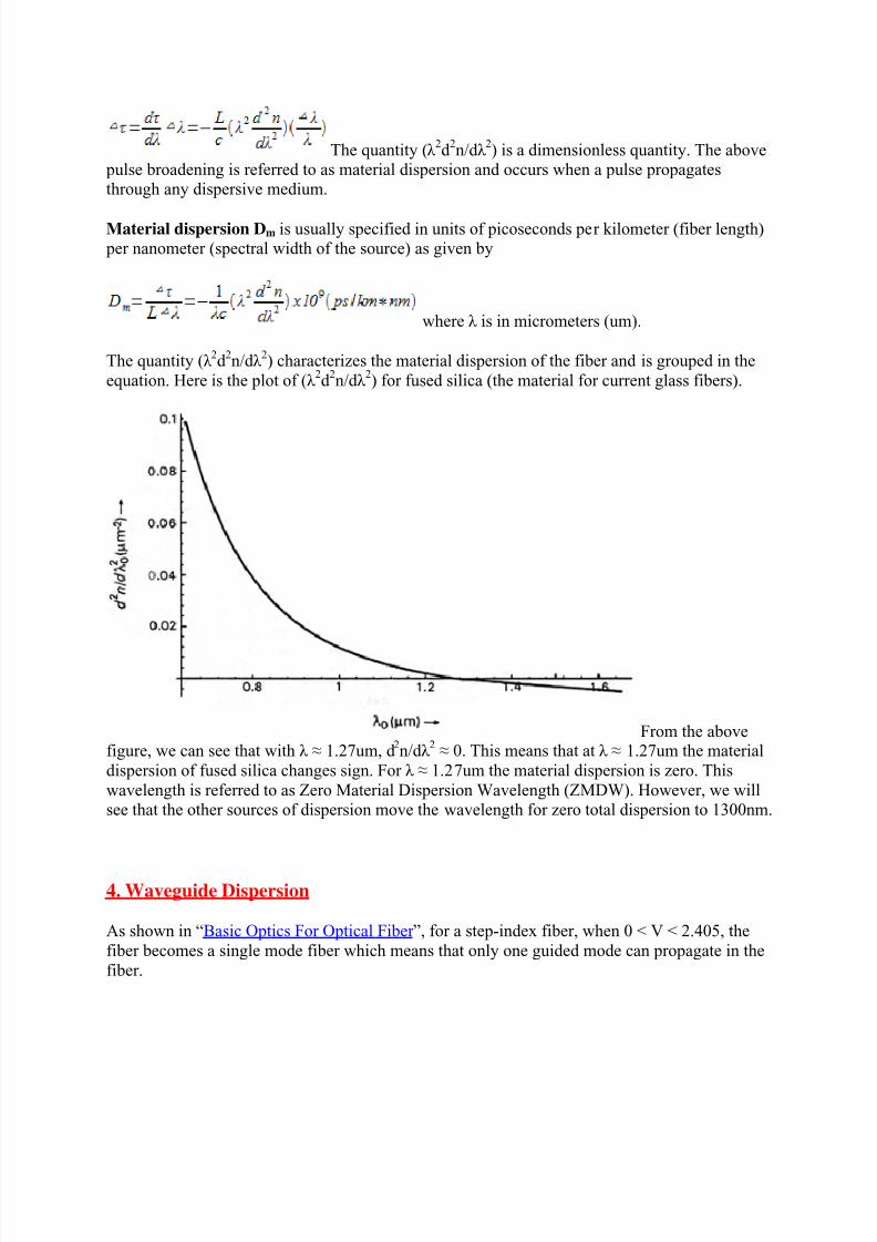
The quantity (λ 2d
2n/dλ
2) characterizes the material dispersion of the fiber and is grouped in the
equation. Here is the plot of (λ 2d
2n/dλ
2) for fused silica (the material for current glass fibers).
From the abovefigure, we can see that with λ ≈ 1.27um, d
2n/dλ
2 ≈ 0. This means that at λ ≈ 1.27um the material
dispersion of fused silica changes sign. For λ ≈ 1.27um the material dispersion is zero. This
wavelength is referred to as Zero Material Dispersion Wavelength (ZMDW). However, we willsee that the other sources of dispersion move the wavelength for zero total dispersion to 1300nm.
4. Waveguide Dispersion
As shown in “Basic Optics For Optical Fiber ”, for a step-index fiber, when 0 < V < 2.405, the
fiber becomes a single mode fiber which means that only one guided mode can propagate in the
fiber.
8/12/2019 Optical Fiber-Dispersion Sp 2014
http://slidepdf.com/reader/full/optical-fiber-dispersion-sp-2014 10/19
In single mode fiber, there is no Modal Dispersion as discussed above. Pulse spreading (pulse
dispersion) happens because of two mechanisms: (1) Material Dispersion as discussed above. (2)
Waveguide Dispersion as will be discussed here.
Waveguide dispersion results from the propagation constant of a mode (its group velocity) being
a function of a/λ (a is fiber’s core radius, λ is light’s vacuum wavelength). Waveguide dispersionis negligible in multimode fibers and in single mode fibers operated at wavelengths below 1um,
but it becomes important for single mode fibers operated in above 1.27um.
The normalized propagation constant b of a mode is defined by
Since, for guided modes β/k 0 lies between n1 and n2, b lies between 0 and 1.
For step-index fibers, b depends only on the V value of the fiber, the above equation can berewritten as
In the above equation, the ≈ step is concluded based on that n1 is very close to n2 which is truefor all practical fibers. Thus we can conclude
The group velocity is given by
In the above equation, n1 and n2 areassumed to be independent of λ.
Since
we have
So
8/12/2019 Optical Fiber-Dispersion Sp 2014
http://slidepdf.com/reader/full/optical-fiber-dispersion-sp-2014 11/19
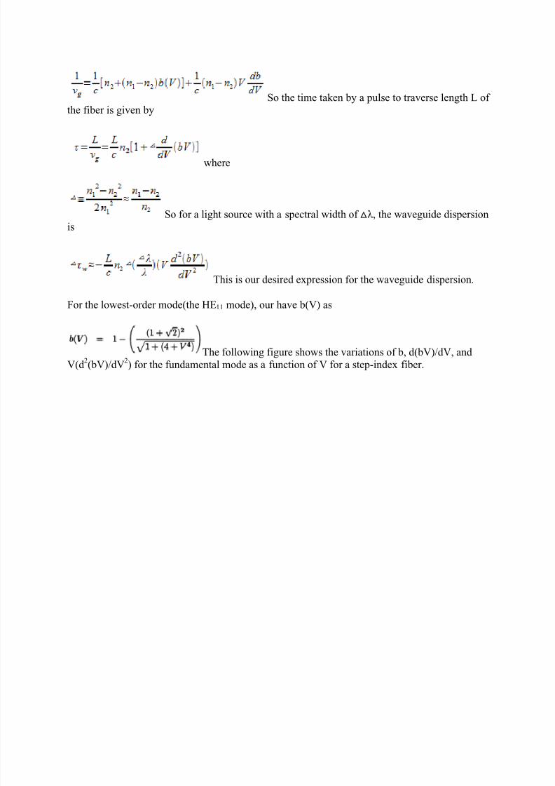
So the time taken by a pulse to traverse length L ofthe fiber is given by
where
So for a light source with a spectral width of △λ, the waveguide dispersion
is
This is our desired expression for the waveguide dispersion.
For the lowest-order mode(the HE11 mode), our have b(V) as
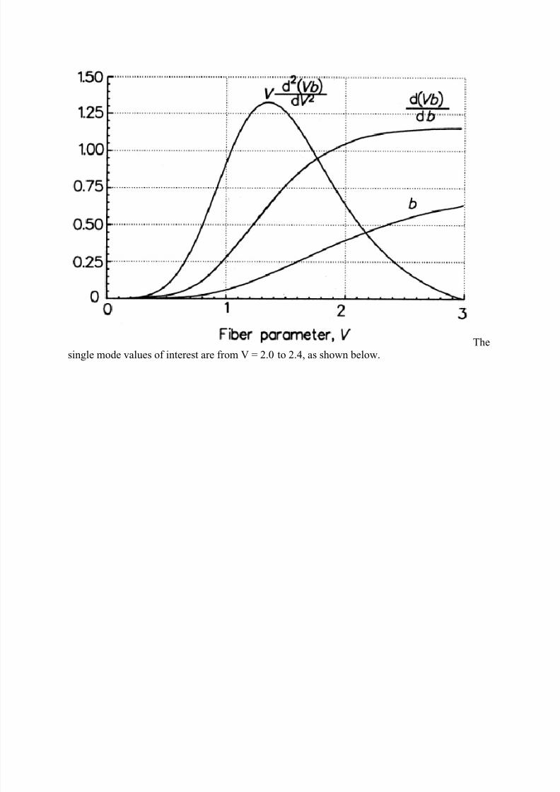
The following figure shows the variations of b, d(bV)/dV, and
V(d 2(bV)/dV
2) for the fundamental mode as a function of V for a step-index fiber.
8/12/2019 Optical Fiber-Dispersion Sp 2014
http://slidepdf.com/reader/full/optical-fiber-dispersion-sp-2014 12/19
8/12/2019 Optical Fiber-Dispersion Sp 2014
http://slidepdf.com/reader/full/optical-fiber-dispersion-sp-2014 13/19
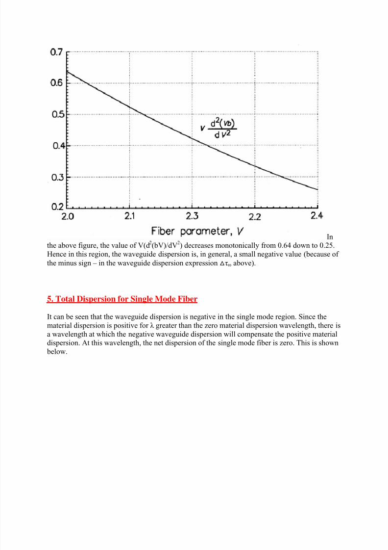
Inthe above figure, the value of V(d
2(bV)/dV
2) decreases monotonically from 0.64 down to 0.25.
Hence in this region, the waveguide dispersion is, in general, a small negative value (because of
the minus sign – in the waveguide dispersion expression △τω above).
5. Total Dispersion for Single Mode Fiber
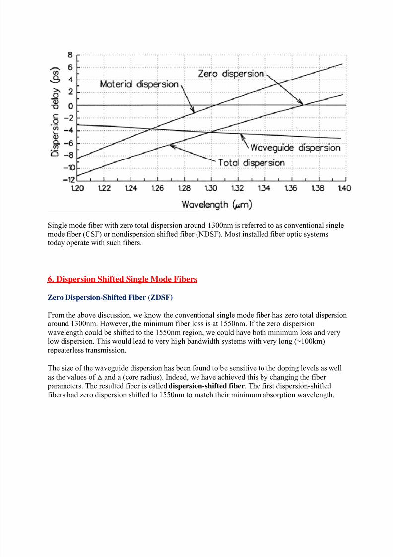
It can be seen that the waveguide dispersion is negative in the single mode region. Since the
material dispersion is positive for λ greater than the zero material dispersion wavelength, there is
a wavelength at which the negative waveguide dispersion will compensate the positive materialdispersion. At this wavelength, the net dispersion of the single mode fiber is zero. This is shown
below.
8/12/2019 Optical Fiber-Dispersion Sp 2014
http://slidepdf.com/reader/full/optical-fiber-dispersion-sp-2014 14/19
Single mode fiber with zero total dispersion around 1300nm is referred to as conventional singlemode fiber (CSF) or nondispersion shifted fiber (NDSF). Most installed fiber optic systems
today operate with such fibers.
6. Dispersion Shifted Single Mode Fibers
Zero Dispersion-Shifted Fiber (ZDSF)
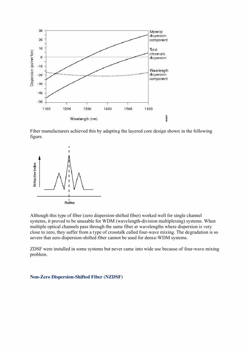
From the above discussion, we know the conventional single mode fiber has zero total dispersion
around 1300nm. However, the minimum fiber loss is at 1550nm. If the zero dispersion
wavelength could be shifted to the 1550nm region, we could have both minimum loss and verylow dispersion. This would lead to very high bandwidth systems with very long (~100km)
repeaterless transmission.
The size of the waveguide dispersion has been found to be sensitive to the doping levels as well
as the values of △ and a (core radius). Indeed, we have achieved this by changing the fiber parameters. The resulted fiber is called dispersion-shifted fiber. The first dispersion-shifted
fibers had zero dispersion shifted to 1550nm to match their minimum absorption wavelength.
8/12/2019 Optical Fiber-Dispersion Sp 2014
http://slidepdf.com/reader/full/optical-fiber-dispersion-sp-2014 15/19
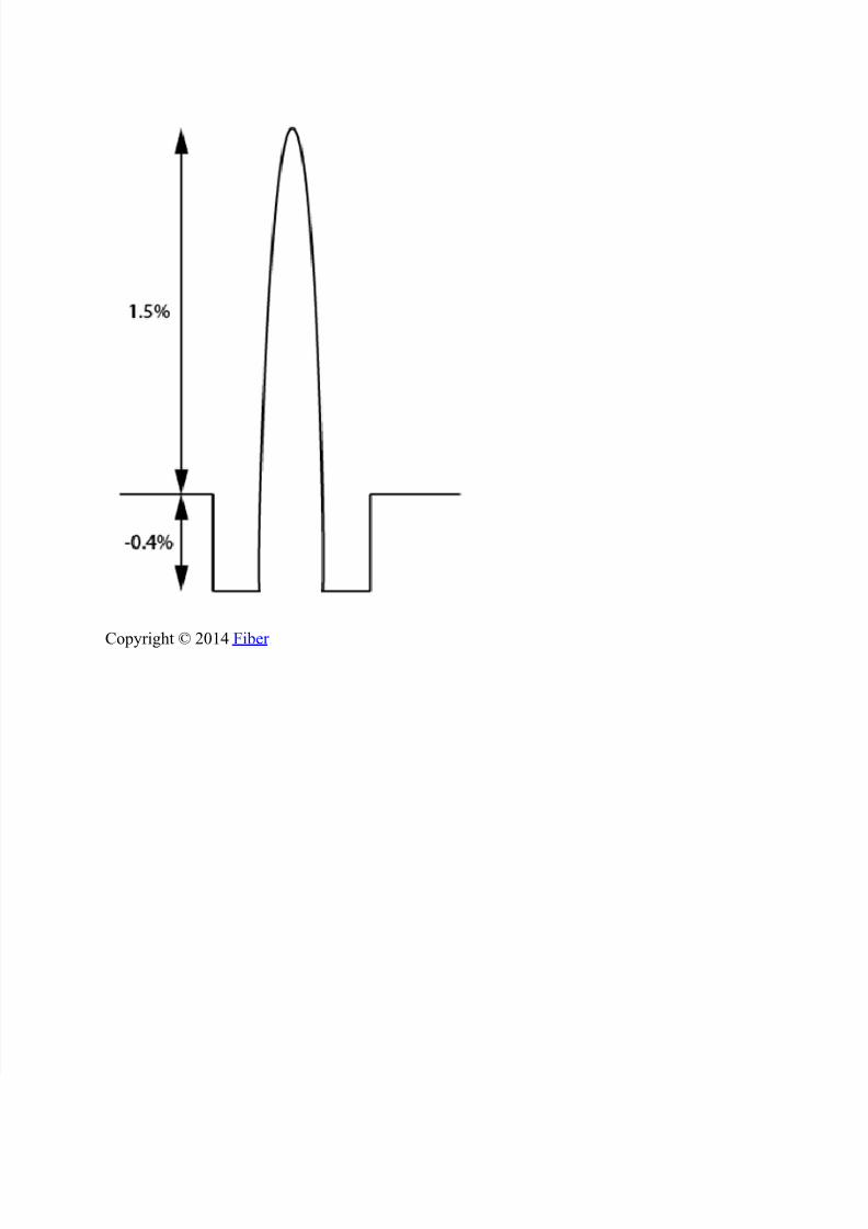
Fiber manufacturers achieved this by adapting the layered core design shown in the followingfigure.
Although this type of fiber (zero dispersion-shifted fiber) worked well for single channel
systems, it proved to be unusable for WDM (wavelength-division multiplexing) systems. When
multiple optical channels pass through the same fiber at wavelengths where dispersion is very
close to zero, they suffer from a type of crosstalk called four-wave mixing. The degradation is sosevere that zero dispersion-shifted fiber cannot be used for dense-WDM systems.
ZDSF were installed in some systems but never came into wide use because of four-wave mixing problem.
Non-Zero Dispersion-Shifted Fiber (NZDSF)
8/12/2019 Optical Fiber-Dispersion Sp 2014
http://slidepdf.com/reader/full/optical-fiber-dispersion-sp-2014 16/19
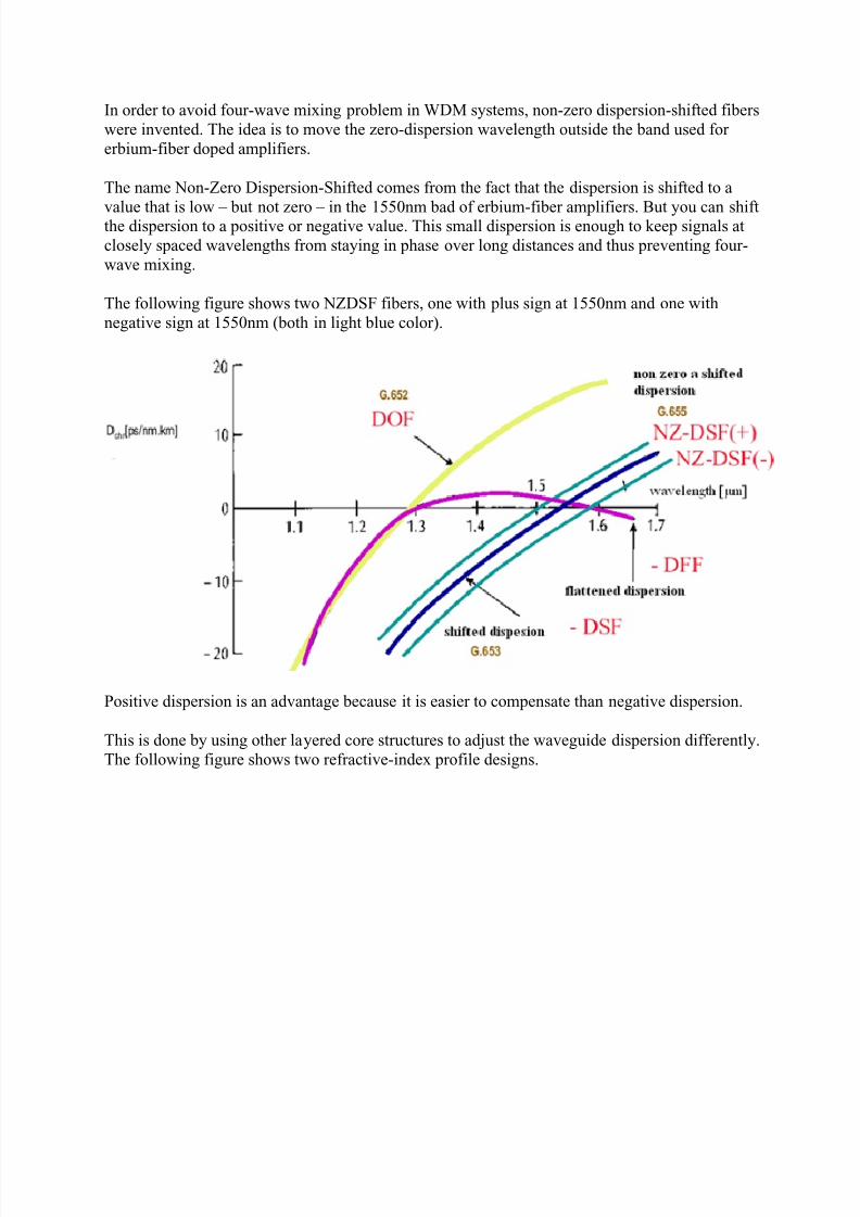
In order to avoid four-wave mixing problem in WDM systems, non-zero dispersion-shifted fibers
were invented. The idea is to move the zero-dispersion wavelength outside the band used for
erbium-fiber doped amplifiers.
The name Non-Zero Dispersion-Shifted comes from the fact that the dispersion is shifted to a
value that is low – but not zero – in the 1550nm bad of erbium-fiber amplifiers. But you can shiftthe dispersion to a positive or negative value. This small dispersion is enough to keep signals at
closely spaced wavelengths from staying in phase over long distances and thus preventing four-
wave mixing.
The following figure shows two NZDSF fibers, one with plus sign at 1550nm and one with
negative sign at 1550nm (both in light blue color).
Positive dispersion is an advantage because it is easier to compensate than negative dispersion.
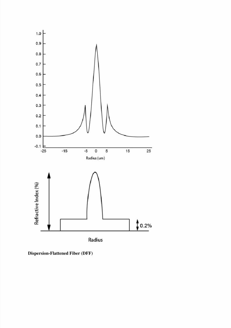
This is done by using other layered core structures to adjust the waveguide dispersion differently.
The following figure shows two refractive-index profile designs.
8/12/2019 Optical Fiber-Dispersion Sp 2014
http://slidepdf.com/reader/full/optical-fiber-dispersion-sp-2014 17/19
Dispersion-Flattened Fiber (DFF)
8/12/2019 Optical Fiber-Dispersion Sp 2014
http://slidepdf.com/reader/full/optical-fiber-dispersion-sp-2014 18/19
Another way to minimize dispersion effects for dense-WDM systems is to reduce the slope of
the dispersion curve. This is called Dispersion-Flattened Fiber (DFF) as shown in the 3rd figure
above in pink color.
The reduced dispersion curve slope helps to simplify the task of dispersion compensation for
systems with many optical channels, but there are tradeoffs. An important one is that dispersion-flattened fiber designs tend to have smaller mode-field diameter which concentrate optical power
in a smaller volume. The increased power density in fiber can cause non-linear effects.
Dispersion-Compensating Fiber
Now, in many countries, tens of millions of miles of CSF (Conventional Single Mode Fiber withzero dispersion near 1300nm) already exist in the underground ducts operating at 1300nm. One
could increase the transmission capacity by operating these fibers at 1550nm and using WDM
techniques and optical amplifiers. But, then there will be significant residual (positive)dispersion. On the other hand, replacing these fibers by non-zero dispersion-shifted fibers would
involve huge cost.
In recent years, there has been considerable work in upgrading the installed 1300nm optimized
fiber links for operation at 1550nm. This is achieved by developing fibers with very large
negative dispersion coefficients, a few hundred meters to a kilometer, which can be used tocompensate for dispersion over tens of kilometers of the fiber in the link.
These fibers tend to have a high-index difference between core and cladding, and often have asmall effective area. The following figure shows the refractive-index profile of one design.
8/12/2019 Optical Fiber-Dispersion Sp 2014
http://slidepdf.com/reader/full/optical-fiber-dispersion-sp-2014 19/19


![Simultaneous dispersion measurements of multiple fiber ...dispersion measurement in a higher-order-mode fiber,” Opt. Lett. 37(3), 347–349 (2012). ... the fundamental [16] as it](https://img.pdfslide.us/doc/110x75/5f7f5ac01f1e4a75d5301076/simultaneous-dispersion-measurements-of-multiple-fiber-dispersion-measurement.jpg)