Embed Size (px)
Citation preview
FIBER OPTICS COMMUNICATION
Presented by
NIKHILKUMAR. A. JAIN VISHAL.K.DHARAMDASANI [email protected] [email protected]
II SEMESTERDEPARTMENT OF
ELECTRONICS AND COMMUNICATION ENGINEERING
GOGTE INSTITUTE OF TECHNOLOGYUDYAMBAG, BELGUAM,
KARNATAKA-590008.
CONTENTS...
Abstract
1.0 Introduction
1.1 What is Fiber Optics Communication?
1.2 Invention of Fiber Optics
1.3 Principal
2.0 Types of Optical Fibers
3.0 The Fiber Optics Data Communications link, End-to-End
4.0 Fiber Optics Communication Networks
4.1 Asynchronous Transfer Mode (ATM)
4.2 Integrated Services Digital Network (ISDN)
4.3 Ethernet
5.0 Areas of application
6.0 Merits
7.0 Demerits
8.0 Figures
9.0 Conclusion
10.0 References
ABSTRACT:
Our current ‘age of technology’ is the result of many brilliant inventions and
discoveries, but it is our ability to transmit information, and the media we use to do it,
that is perhaps most responsible for its evolution. Progressing from the copper wire of a
century ago to today's fiber optic cable, our increasing ability to transmit more
information, more quickly and over longer distances has expanded the boundaries of our
technological development in all areas. An optical fiber communication is a transmission
medium designed to transmit digital signals in the form of pulses of light using optical
fibers. In its simplest terms, fiber optics is a medium for carrying information from one
point to another in the form of light. Unlike the copper form of transmission, fiber optics
is not electrical in nature.
Today's low-loss glass fiber optic cable offers almost unlimited bandwidth and
unique advantages over all previously developed transmission media.
In our treatise we explain the concept of fiber optics, it’s principle, fiber optics
data communication link, end-to-end. This article discusses these standards and
protocols, including ATM (Asynchronous Transfer Mode) Ethernet, ISDN (Integrated
Service Data Interface) and areas of application.
Word count: 194
1.0 INTRODUCTION:
1.1 What is Fiber Optics Communication?
A transmission medium designed to transmit digital signals in the form of pulses
of light. These pulses of light are transferred through the optical fibers. The transmission
media is the fiber optics itself. They guide visible and infrared light over long distances.
The optical fiber made up of an insulating material like glass, plastic etc. Fiber Optics
doesn't suffer from either line of sight or absorption under normal circumstances. Fiber
optic systems use a laser beam fired into a special glass or plastic fiber with a transparent
core. The fiber is designed to allow light to be transmitted along its length. It is specially
made to reflect light that reaches the outer edge of its core, and gently deflect the light
wave back to the center of the fiber. Thus, the light signal can be bent around corners.
The fiber is sealed, thus preventing water from getting in the way. These fibers are tiny.
Several fibers together are the width of a human hair, and each fiber can carry thousands
of connections (refer figure1.1a). Telecommunications companies use fiber optics most
frequently. Most fiber optic cable is buried in the ground, so water sometimes creeps in
and causes attenuation, but this is increasingly rare. Because fiber optics are so reliable,
and difficult to disrupt (it practically takes a backhoe to stop it), they are the most popular
form of long distance communication in use today.
The optical fiber construction: (refer figure 1.1b)
CORE – it’s made of glass.
CLADDING - made of glass.
Plastic coating.
1.2 Invention of optical fiber
British physics John Tyndall nearly 120 years ago demonstrated
experimentally that light could be guided along a curved steam of water employing
optical phenomena of total internal reflection. Based on this concept the first glass fibers
were made in 1920’s but the concept of cladding made guiding of light practical with
limited success in 1950.
It is the invention of lasers in1960 by Maiman, which created a sensation in
optical communication because of its high coherence property. The optical frequencies
are of order of 5x10¹⁴Hz,as compared to the frequencies of up to 1010 Hz employed in
electric communication such as TV, radar, and microwave links. This indicates an
increase of information capacity 104 times in optical range.
In recent years it has become apparent that fiber optics are steadily replacing
copper wire as an appropriate means of communication signal transmission. They span
the long distances between local phone systems as well as providing the backbone for
many network systems. Other system users include cable television services, university
campuses, office buildings, industrial plants, and electric utility companies.
1.3 Principle
Think of a fiber cable in terms of very long cardboard roll (from the inside roll of
paper towel) that is coated with a mirror. If you shine a flashlight in one you can see light
at the far end - even if bent the roll around a corner.
Light pulses move easily down the fiber-optic line because of a principle known as
‘total internal reflection’2. This principle of total internal reflection states ‘that when the
angle of incidence exceeds a critical value, light cannot get out of the glass; instead, the
light bounces back in’. When this principle is applied to the construction of the fiber-
optic strand, it is possible to transmit information down fiber lines in the form of light
pulses. (Refer figure 1.3a).
2.0 Types of optical fiber
1.Step Index Multimode Fiber (refer figure 2.0a)
o Bandwidth - 20 MHz
o Core diameter - 100-250 microns
2.Graded Index Multimode Fiber (refer Figure2.0c)
o Bandwidth - 800 MHz
o Core diameter - 50-100 microns
3.Step Index Single Mode Fiber (refer Figure 2.0b)
o Bandwidth - 5 GHz
o Core diameter - 5-7 microns
3.0 The Fiber Optic Data Communications Link, End-to-End
This shows the simple fiber optic data link for the premises environment. This is the
basic building block for a fiber optic based network.
Model of simple fiber optic data link
Fiber optic transmission uses the same basic elements as copper-based
transmission systems: A transmitter, a receiver, and a medium by which the signal is
passed from one to the other, in this case, optical fiber.
TRANSMITTER:
The transmitter uses an electrical interface to encode the use information through AM,
FM or digital modulation. A laser diode or an LED does the encoding to allow an optical
output of 850 nm, 1310 nm, or 1550 nm (typically). Light Sources
There are two main light sources used in the field of fiber optics. –
1. (LD’s) Light Emitting diodes (LED’s)
2. Laser Diodes
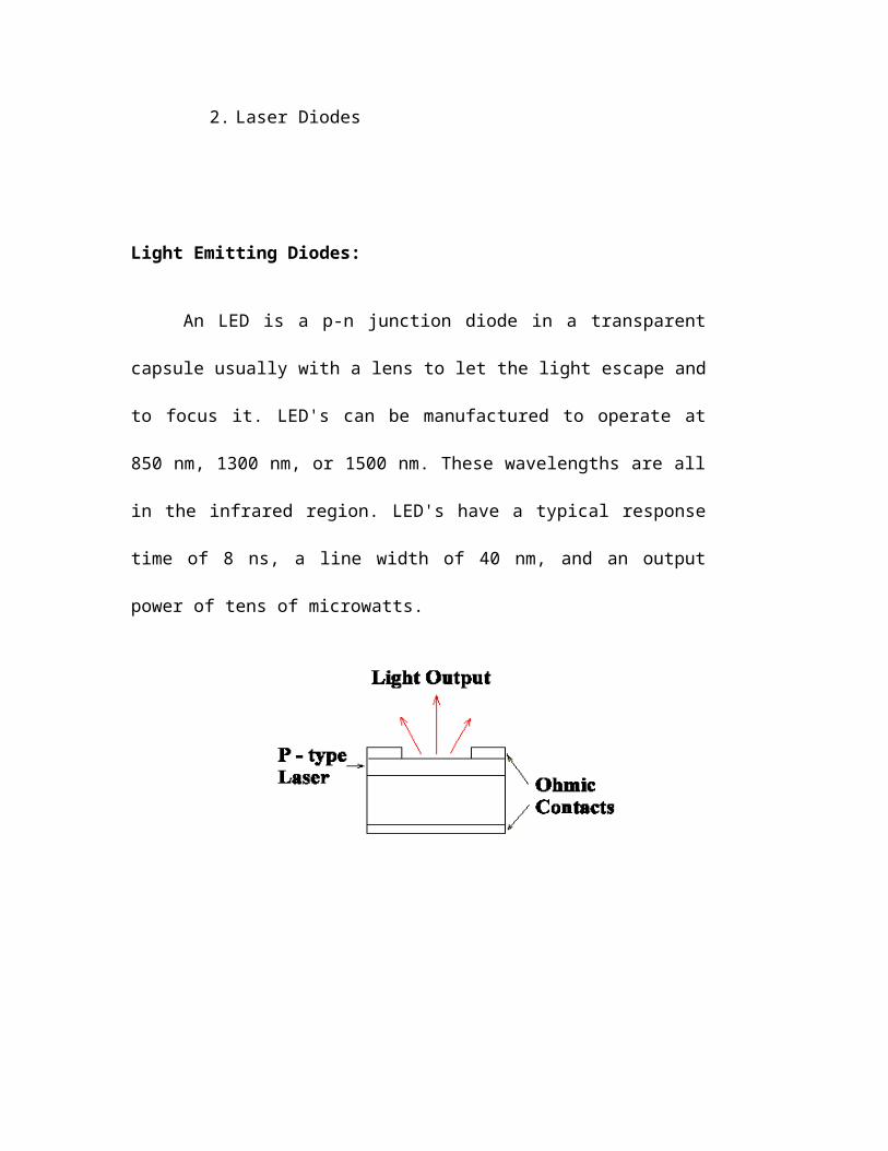
Light Emitting Diodes:
An LED is a p-n junction diode in a transparent capsule usually with a lens
to let the light escape and to focus it. LED's can be manufactured to operate at 850
nm, 1300 nm, or 1500 nm. These wavelengths are all in the infrared region.
LED's have a typical response time of 8 ns, a line width of 40 nm, and an output
power of tens of microwatts.
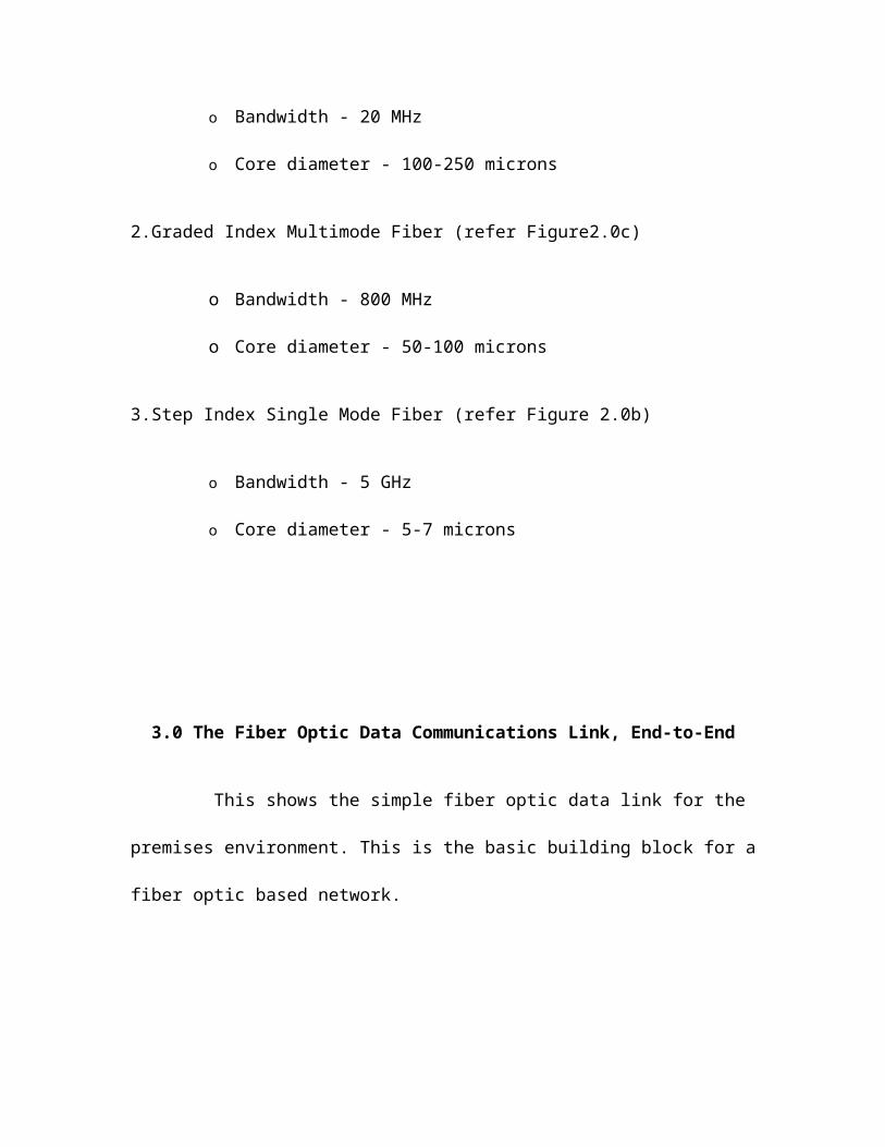
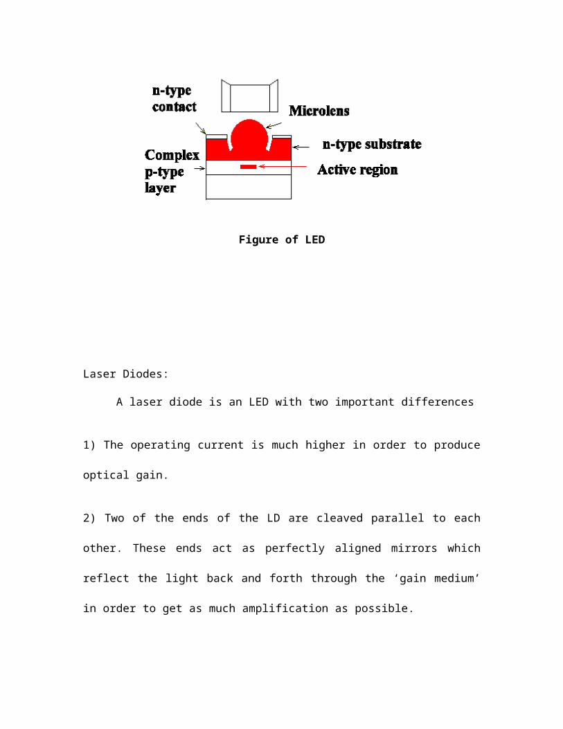
Figure of LED
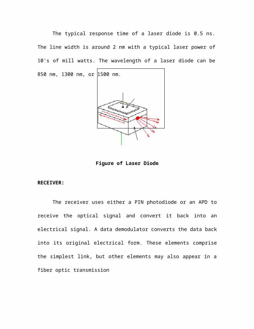
Laser Diodes:
A laser diode is an LED with two important differences
1) The operating current is much higher in order to produce optical gain.
2) Two of the ends of the LD are cleaved parallel to each other. These ends act as
perfectly aligned mirrors which reflect the light back and forth through the ‘gain
medium’ in order to get as much amplification as possible.
The typical response time of a laser diode is 0.5 ns. The line width is around 2
nm with a typical laser power of 10's of mill watts. The wavelength of a laser diode can
be 850 nm, 1300 nm, or 1500 nm.
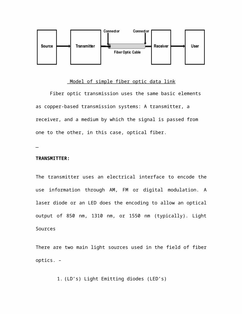
Figure of Laser Diode
RECEIVER:
The receiver uses either a PIN photodiode or an APD to receive the optical signal
and convert it back into an electrical signal. A data demodulator converts the data back
into its original electrical form. These elements comprise the simplest link, but other
elements may also appear in a fiber optic transmission
Long distance fiber optic transmission leads to further system complexity. Many
long-haul transmission systems require signal regenerators, signal repeaters, or optical
amplifiers such as EDFAs in order to maintain signal quality. System drop/repeat/add
requirements, such as those in multichannel broadcast networks, further add to the fiber
optic system, incorporating multiplexes, couplers/splitters, signal fan outs, dispersion
management equipment, remote monitoring interfaces, and error-correction components.
4.0 Fiber Optic Communications Networks
All networks involve the same basic principle: information can be sent to, shared
with, passed on, or bypassed within a number of computer stations (nodes) and a master
computer (server). In addition to various topologies for networks a number of standards
and protocols have been developed, each with their own advantages, topologies, and
medium requirements. This discusses these standards and protocols, including: ATM,
Ethernet & ISDN.
4.1 Asynchronous Transfer Mode (ATM)
Asynchronous transfer mode (ATM) is widely deployed as a network backbone
technology. This technology integrates easily with other technologies, and offers
sophisticated network management features that allow signal carriers to guarantee
Quality Of Service (QOS). ATM may also be referred to as cell relay because the
network uses short, fixed length packets or cells for data transport. The information is
divided into different cells, transmitted, and re-assembled at the receiving end. Each cell
contains 48 bytes of data payload as well as a 5-byte cell header. This fixed size ensures
that time critical voice or video data will not be adversely affected by long data frames or
packets.
ATM organizes different types of data into separate cells, allowing network users
and the network itself to determine how bandwidth is allocated. This approach works
especially well with networks handling burst data transmissions. Data streams are then
multiplexed and transmitted between end user and network server and between network
switches. These data streams can be transmitted to many different destinations, reducing
the requirement for network interfaces and network facilities, and ultimately, overall cost
of the network itself.
Connections for ATM networks include Virtual Path Connections (VPCs), which
contain multiple Virtual Circuit Connections (VCCs). Virtual circuits are nothing more
than end-to-end connections with defined endpoints and routes, but no defined bandwidth
allocation. Bandwidth is allocated on demand as required by the network. VCCs carry a
single stream of contiguous data cells from user to user. VCCs may be configured as
static, Permanent Virtual Connections (PVCs) or as dynamically controlled Switched
Virtual Circuits (SVCs). When VCCs are combined into VPCs, all cells in the VPC are
routed the same way, allowing for faster recovery of the network in the event of a major
failure.
While ATM still dominates WAN backbone configurations, an emerging
technology, Gigabit Ethernet, may soon replace ATM in some network scenarios,
especially in LAN and desktop scenarios. A discussion of Ethernet follows.
4.2 Integrated Services Digital Network (ISDN)
ISDN has been designed to replace the standard telephone system and provide
greater numbers of digital services to telephone customers, such as digital audio,
interactive information services, fax, e-mail, and digital video. ISDN uses asynchronous
transfer mode, which can handle data transmission in both connection-oriented, and
packet schemes. As with regular telephone lines, the user must pay a fee for use of the
line. Basic rate ISDN offers two simultaneous 64 kb/s data channels as well as a 16 kb/s
carrier channel for signaling and control information. The combined data rate, 128 kb/s,
allows for videoconferencing capabilities. Multiple ISDN-B connections further increase
the data rate and the transmission quality. Primary rate ISDN (PRI) offers 30 channels (of
64 kb/s each), giving a total of 1920 kb/s. As with BRI, each channel can be connected to
a different destination, or they can be combined to give a larger bandwidth. These
channels, known as ‘bearer’ or ‘B’ channels, give ISDN tremendous flexibility.
The original version of ISDN employs base band transmission. Another version,
called B-ISDN, uses base band transmission and is able to support transmission rates of
1.5 Mb/s. B-ISDN requires fiber optic cables and is not yet widely available.
4.3 Ethernet
Ethernet began as a laboratory experiment for Xerox Corporation in the 1970’s.
Designers intended Ethernet to become a part of the ‘Office of the future’, which would
include personal computer workstations. By 1980, formal Ethernet specifications had
been devised by a multi-vendor consortium. Widely used in today’s LANs, Ethernet
transmits at 10 Mb/s using twisted-pair coax cable and/or optical fiber. Fast Ethernet,
transmits at 100 Mb/s, and the latest developing standard, gigabit Ethernet, transmits at
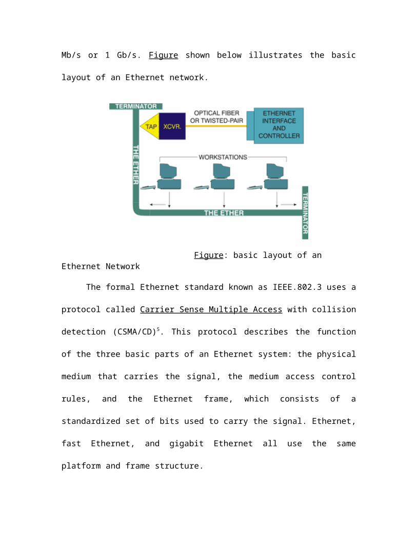
1,000 Mb/s or 1 Gb/s. Figure shown below illustrates the basic layout of an Ethernet
network.
Figure: basic layout of an Ethernet Network
The formal Ethernet standard known as IEEE.802.3 uses a protocol called Carrier
Sense Multiple Access with collision detection (CSMA/CD)5. This protocol describes the
function of the three basic parts of an Ethernet system: the physical medium that carries
the signal, the medium access control rules, and the Ethernet frame, which consists of a
standardized set of bits used to carry the signal. Ethernet, fast Ethernet, and gigabit
Ethernet all use the same platform and frame structure.
Ethernet users have three choices for physical medium. At 1 to 10 Mb/s, the
network may transmit over thick coaxial cable, twisted-pair coax cable or optical fiber.
Fast 100 Mb/s Ethernet will not transmit over thick coax, but can use twisted pair or
optical fiber as well. Gigabit Ethernet, with greater data rate and longer transmission
distance, uses optical fiber links for the long spans, but can also use twisted-pair for short
connections.
CSMA/CD represents the second element, the access control rules. In this
protocol, all stations must remain quiet for a time to verify no station in the network is
transmitting before beginning a transmission. If another station begins to signal, the
remaining stations will sense the presence of the signal carrier and remain quiet. All
stations share this multiple access protocol. However, because not all stations will receive
a transmission simultaneously, it is possible for a station to begin signaling at the same
time another station does. This causes a collision of signals, which is detected by the
station speaking out of turn, causing the station to become quiet until access is awarded,
at which time the data frame is resent over the network.
The final element, the Ethernet frame, delivers data between workstations based
on a 48-bit source and destination address field. The Ethernet frame also includes a data
field, which varies in size depending on the transmission, and an error-checking field,
which verifies the integrity of the received data. As a frame is sent, each workstation
Ethernet interface reads enough of the frame to learn the 48-bit address field and
compares it with its own address. If the addresses match, the workstation reads the entire
frame, but if the addresses do not match, the interface stops reading the frame.
Ethernet at all data rates has become a widely installed network for Local Area
Network (LAN), MAN, and Wide Area Network (WAN) applications. Its ability to
interface with Synchronous Optical Network (SONET) and ATM networks will continue
to support this popular network. In LANs, Ethernet links offer a scalable backbone, and a
high-speed campus data center backbone with inter-switch extensions. As a metro
backbone in MANs, gigabit Ethernet will interface in DWDM systems, allowing long
haul, high-speed broadband communications networks. Finally, Ethernet supports all
types of data traffic including data, voice, and video over IP. Figure illustrates a typical
Ethernet deployment scenario.
Figure: – Switched, Routed Gigabit Ethernet Network
Gigabit Ethernet has emerged as a cost-effective alternative to ATM network
structures. ATM has a greater cost, and he standards and products used to transmit ATM
are still in flux, unlike the proven paradigm of Ethernet. In addition, system complexity is
reduced in gigabit Ethernet, and because it works with existing Ethernet formats, the
system does not require emulation software to act as a gateway between an Ethernet LAN
and an ATM network. Table.1 outlines how Ethernet and gigabit Ethernet offer the same
benefits of ATM.
Areas of application:
Tele communication:
Optical fibers are now the standard point-to-point cable link between telephone
sub stations. It is said that currently, the fastest fibers circuits used in trunk connections
between cities and countries carry information at up to 2.5 giga bytes per second, enough
to carry 40,000 telephone conversations. Experts predict larger bandwidths than this as
light frequencies suppression becomes available.
Local area networks (LAN’s):
Multimode fiber is commonly used as the backbone to carry signals between the
hubs of a LAN’s from where copper coaxial cable takes the data to the desktop. Fiber
links to the desktop, however, are also common.
Cable TV:
The domestic cable TV networks use optical fiber because of its very low power
consumption. The fastest fiber circuits carry information at up to 250 television channels.
CCTV:
Closed Circuit Television security systems use optical fiber because of its
inherent security, as well as the other advantages mentioned above.
Optical fiber sensors:
Many advances have been made in recent years in the use of optical fiber sensors.
Gas concentration, chemical concentration, pressure, temperature and rate of rotation can
all be sensed using optical fiber.
5.0 Merits
1. Immunity to electromagnetic interference and crosswalk.
2. No electrical ground loop or short circuit problems.
3. Small size and lightweight.
4. Large bandwidth for size and weight.
5. Safe in combustible areas (no arching).
6. Immunity to lightning and electrical discharges.
7. Longer cable runs between repeaters.
8. Flexibility and high strength.
9. Potential high temperature operation.
10. Resistant to nuclear radiation.
11. Secure against signal leakage and interference.
12. No electrical hazard when cut or damaged.
13. Compatible with future bandwidth requirements and future LAN standards.
(FDDI, ATM)
14. The dielectric nature of optical fiber can eliminate the dangers found in areas of
high lightning strike incident
15.Non-Conductivity: Another advantage of optical fibers is their dielectric nature.
Since optical fiber has no metallic components, it can be installed in areas with
electromagnetic interference (EMI), including Radio Frequency Interference (RFI).
Areas with high EMI include utility lines, power-carrying lines, and railroad tracks.
All-dielectric cables are also ideal for areas of high lightning-strike incidence.
16.Security: Unlike metallic-based systems, the dielectric nature of optical fiber
makes it impossible to remotely detect the signal being transmitted within the cable.
Only way to do so is by actually accessing the optical fiber itself. Accessing fiber
requires intervention that is easily detectable by security surveillance. These
circumstances make fiber extremely attractive to governmental bodies, banks, and
others with security concerns.
17.Designed for Future Applications Needs: Fiber optics is affordable today, as
electronics prices fall and optical cable pricing remains low. In many cases, fiber
solutions are less costly than copper.
6.0 Demerits
1. Relatively expensive cable cost and installation cost.
2. Requires specialist knowledge and test equipment.
3. No IEEE 802.5 standard published yet.
4. Relatively small installed base.
FIGURES:
(Figure 1.1a) (Figure 1.1b)
THIN OPTICAL FIBERS CONSTRUCTION
(Figure 1.3a)
TOTAL INTERNAL REFLECTION
(FIGURES 2.0a, 2.0b, 2.0c)
Types of optical fibers
CONCLUSION
The development of ultra-high capacity local- and wide-area computer networks
is also of interest to address the exponential growth of Internet traffic. The development
of high-speed multimedia networks puts increasing demand for higher bandwidth
channels and networks. Such demands may require transmission of information at an
ultra-high bit rate of terabits/sec over fiber optics. Thus Fiber Optics will play a pivotal
role in this race since the bandwidth needed for providing an all in-one service with
television, telephone, interactive multimedia, and Internet access is not available in much
of the wiring.
REFERENCES
1. ‘Optical Transmission Medium’, by Pradeep Atria, pp.16-21, ‘Electronics
Makers’ June 2004 ed.
2. www.fiber-optics.com
3. www.engineeringlab.com/fiber optic6.htm
4. www.optics2001.com
5. www.fiber-optics.info