Embed Size (px)
Citation preview

Operator’s Manual
Wheel Loader WL 25
www.wackerneuson.com

August 08 Edition

You have opted for a Wacker Neuson loader – thank you very much for putting your trust in us.
Your Wacker Neuson loader is a powerful product with robust technology and a wide range of applications to aid you in your day-to-day work. In order to familiarize yourself with your loader in a quick, comprehensive manner, please read this operator’s manual attentively.
In addition to the information regarding operation, this operator’s manual also contains important maintenance and op-erating instructions for conserving the value of your loader. Furthermore, we will show you how to operate your loader in an environmentally sound manner.
Should you have any questions or problems relating to your loader, please contact your Wacker Neuson partner or im-porter. They will be happy to respond to your questions, suggestions or criticisms at any time.
We are confident that you will be very satisfied with your new Wacker Neuson loader.
Wacker Neuson Construction Equipment AG
CONTENTS2
TABLE OF CONTENTS
PREFACE ............................................................................................................................................................... 7
1 BASIC INFORMATION ..................................................................................................................................... 81.1 Notes about this Operator’s Manual ....................................................................................................... 91.2 Explanation of the symbols used in this operator’s manual .................................................................. 101.3 Warranty and liability............................................................................................................................. 111.4 Intended use ......................................................................................................................................... 12
2 BASIC SAFETY INSTRUCTIONS .................................................................................................................. 142.1 Organizational measures ...................................................................................................................... 152.2 Selection and qualification of personnel / basic duties ......................................................................... 172.3 Safety instructions for certain operating phases .................................................................................. 182.3.1 Safety instructions for normal operation ............................................................................................... 182.3.2 Safety instructions for other operating modes ...................................................................................... 202.4 Safety instructions for particular hazards ............................................................................................. 232.4.1 Forklift attachment ................................................................................................................................ 232.4.2 Working near overhead power Lines .................................................................................................... 242.4.3 Electrical power..................................................................................................................................... 252.4.4 Flying sparks / fire danger ..................................................................................................................... 252.4.5 Gas, dust, steam, smoke ...................................................................................................................... 262.4.6 Hydraulics, pneumatics ......................................................................................................................... 262.4.7 Tip-overs ............................................................................................................................................... 272.4.8 Noise ..................................................................................................................................................... 272.4.9 Oils, grease and other chemical substances ........................................................................................ 272.5 Transporting and towing / restarting ..................................................................................................... 28

CONTENTS 3WL25
2.6 Final decommissioning / dismantling .................................................................................................... 282.7 Safety labels used ................................................................................................................................. 292.8 Safety devices ....................................................................................................................................... 342.8.1 Fire extinguisher ................................................................................................................................... 342.8.2 Rotating beacon .................................................................................................................................... 342.8.3 Seat belt ................................................................................................................................................ 352.8.4 Backup alarm for reverse drive ............................................................................................................. 352.8.5 Emergency exit ..................................................................................................................................... 362.8.6 Battery disconnect switch ..................................................................................................................... 372.8.7 Loader lift arm locking system .............................................................................................................. 38
3 TECHNICAL DATA .......................................................................................................................................... 393.1 Technical description ............................................................................................................................ 393.2 Loader data ........................................................................................................................................... 413.3 Product identification number plates ..................................................................................................... 433.4 Dimensions ........................................................................................................................................... 44
4 DESCRIPTION OF THE INDICATOR, WARNING AND CONTROL ELEMENTS ......................................... 464.1 Operating elements and instruments .................................................................................................... 464.2 Control and warning lights .................................................................................................................... 484.3 Switches / rocker switches .................................................................................................................... 504.4 Indicator devices ................................................................................................................................... 52
5 OPERATING AND OPERATION .................................................................................................................... 545.1 Before starting up ................................................................................................................................. 54

CONTENTS4
5.1.1 Fueling .................................................................................................................................................. 545.1.2 Operation .............................................................................................................................................. 565.1.3 Doors and windows............................................................................................................................... 585.1.4 Adjusting the operator’s seat ................................................................................................................ 595.1.5 Adjusting the steering column ............................................................................................................... 615.1.6 Seat belt ................................................................................................................................................ 625.2 Starting up ............................................................................................................................................ 655.2.1 Lighting system and forward warning device ........................................................................................ 665.2.2 Wipers and windshield washer system ................................................................................................. 675.2.3 Headlights and rotating beacon ............................................................................................................ 695.2.4 Ventilation and heating of the cab ......................................................................................................... 715.2.5 Before starting the engine ..................................................................................................................... 725.2.6 Starting the engine ................................................................................................................................ 735.3 Propulsion operation ............................................................................................................................. 765.3.1 Preparation for travel in public traffic .................................................................................................... 765.3.2 Travel speed .......................................................................................................................................... 775.3.3 Stopping and parking ............................................................................................................................ 815.4 Work operation ...................................................................................................................................... 825.4.1 Operating lever for Loader lift arms ...................................................................................................... 845.4.2 Operating lever for the optional hydraulics ........................................................................................... 865.4.3 Loader lift arms locking system ............................................................................................................ 885.4.4 Differential lock ..................................................................................................................................... 895.4.5 Changing attachments .......................................................................................................................... 905.4.6 Bucket ................................................................................................................................................... 955.4.7 Tip-overs ............................................................................................................................................. 1015.4.8 Precaution measures for various weather conditions ......................................................................... 102
CONTENTS 5WL25
5.5 Additional equipment .......................................................................................................................... 104
6 TOWING AND TRANSPORTING ..................................................................................................................1106.1 Towing ..................................................................................................................................................1106.2 Transporting .........................................................................................................................................114
7 LOWERING LOADER ARMS........................................................................................................................ 121
8 RELIEVING RESIDUAL PRESSURE IN THE HYDRAULIC SYSTEM ........................................................ 122
9 SECURING THE LOADER ........................................................................................................................... 125
10 SERVICING AND INSPECTION ................................................................................................................... 12610.1 Basic safety instructions for servicing and inspection ........................................................................ 12610.2 Servicing and inspection intervals ...................................................................................................... 13410.3 Lubrication schedule ........................................................................................................................... 14610.4 Cleaning the loader ............................................................................................................................. 14810.5 General safety check .......................................................................................................................... 15010.6 Specifications and filling quantities ......................................................................................................15110.7 Maintenance and inspection work ...................................................................................................... 15210.7.1 Preparation for maintenance and inspection work.............................................................................. 15210.7.2 Servicing the engine ........................................................................................................................... 15810.7.3 Servicing the fuel system .................................................................................................................... 16410.7.4 Servicing the air filter system .............................................................................................................. 16910.7.5 Servicing the cooling system .............................................................................................................. 17210.7.6 Servicing the hydraulic system ........................................................................................................... 178
CONTENTS6
10.7.7 Servicing the axles.............................................................................................................................. 18610.7.8 Servicing the cab vent filter ................................................................................................................. 19010.7.9 Servicing the brakes ........................................................................................................................... 19110.7.10 Servicing the tires and wheels ............................................................................................................ 19310.7.11 Servicing the electrical system ........................................................................................................... 19710.8 Jump-starting / emergency starting .................................................................................................... 20410.9 Loader storage .................................................................................................................................... 207
11 TROUBLESHOOTING AND EMERGENCY MAINTENANCE ...................................................................... 210
12 SAFETY INSTRUCTIONS FOR REPAIRS ................................................................................................... 21412.1 General safety regulations for repairs ................................................................................................. 21412.2 Engine ................................................................................................................................................. 21712.3 Welding work ...................................................................................................................................... 21712.4 Hydraulic system ................................................................................................................................. 21912.5 Brakes ................................................................................................................................................. 219
13 FINAL SHUTDOWN OF THE LOADER / DECOMMISSIONING ................................................................. 220
14 APPENDIx .................................................................................................................................................... 22214.1 Ordering replacement parts ................................................................................................................ 22214.2 Inspection verification ......................................................................................................................... 224Index ............................................................................................................................................................ 228List of figures ...................................................................................................................................................... 232
PREFACE 7WL25
PREFACE
This operator’s manual describes how to operate and service the loader. It provides operating and maintenance person-nel with the necessary knowledge of the loader‘s functional characteristics in order to allow them to operate, diagnose, maintain and repair the loader safely.
Observing the specifications in this operator’s manual as-sures:
proper, safe, professional operation of the loader• professional service, cleaning and care of the loader•
Observe the applicable OSHA 1910 and 1926 safety regula-tions when they apply to the user.
If required, the user/operator should supplement the opera-tor’s manual with instructions and regulations regarding environmental protection and national regulations relating to accident prevention.
All persons involved in work on or with the loader must read and apply this operator’s manual, for example with regard to:
operation, including setup, emergency maintenance • during operation, care, disposal of auxiliary materials and operating materials as well as disposal of the entire loader.maintenance (inspection, servicing, care).• transport.•
Should you have questions about this operator’s manual, please contact your dealer or visit us at www.wackerneuson.com.
The operator’s manual must always be located in the loader or at the place where it is being used.
This operator’s manual is not designed for purposes of extensive maintenance work. Such work must be performed by approved professionals.
BASIC INFORMATION8
Each new user must be instructed before using the loader for the first time.
Instructions for using the operator’s manual:
Read the operator’s manual carefully before starting • up the loaderObserve all the safety instructions• Follow the regulations and laws applicable at the place • of useAlways keep the operator’s manual in a clean, orderly • state together with the loader.
BASIC INFORMATION1
If it is not possible to rule out hazards to persons or material during work according to the loader‘s intended use, these hazards will be indicated by means of safety labels.
Instructions relate to the direction of travel of the loader; this means that, when directional information is given, it can be assumed that this refers to the direction of travel of the loader.
BASIC INFORMATION 9WL25
Notes about this Operator’s Manual1.1
The specifications, illustrations, weight information and technical data are not binding and correspond to the state of the art at the time of printing. We must reserve the right to make changes without prior notice in the area of design, configuration, appearance and technology on account of the ongoing further development of the products.
Please contact us if you need special functions which are only available by using additional components and/or under special general conditions. We are happy to answer your questions and give you information whether, and under which product and environmental conditions, special func-tions are feasible. If you have concerns about the resilience or mode of operation of our products due to special condi-tions, we recommend working with samples under controlled general conditions.
Always strictly observe the safety instructions in this opera-tor’s manual and the legal and trade association regulations at the usage location.
Despite the utmost care, we cannot rule out deviations from drawings or dimensions, computing errors, printing errors or incompleteness in this operator’s manual. Therefore we make no guarantee for the correctness and completeness of our statements in this operator’s manual. We guarantee the faultless functionality of our products within the context of our General Terms and Conditions of Business. As a matter of principle we do not make any further guarantees. Liability other than as mentioned in our General Terms and Conditions is excluded.
BASIC INFORMATION10
Explanation of the symbols used in this operator’s manual1.2
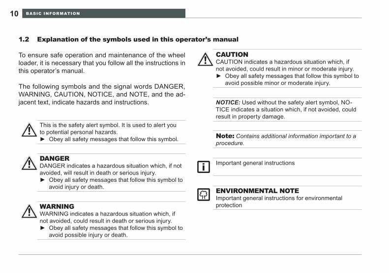
To ensure safe operation and maintenance of the wheel loader, it is necessary that you follow all the instructions in this operator’s manual.
The following symbols and the signal words DANGER, WARNING, CAUTION, NOTICE, and NOTE, and the ad-jacent text, indicate hazards and instructions.
This is the safety alert symbol. It is used to alert you to potential personal hazards.
Obey all safety messages that follow this symbol. ►
DANGERDANGER indicates a hazardous situation which, if not avoided, will result in death or serious injury.
Obey all safety messages that follow this symbol to ►avoid injury or death.
WARNINGWARNING indicates a hazardous situation which, if not avoided, could result in death or serious injury.
Obey all safety messages that follow this symbol to ►avoid possible injury or death.
CAUTIONCAUTION indicates a hazardous situation which, if not avoided, could result in minor or moderate injury.
Obey all safety messages that follow this symbol to ►avoid possible minor or moderate injury.
NOTICE: Used without the safety alert symbol, NO-TICE indicates a situation which, if not avoided, could result in property damage.
Important general instructions
ENVIRONMENTAL NOTEImportant general instructions for environmental protection
Note: Contains additional information important to a procedure.
BASIC INFORMATION 11WL25
Warranty and liability1.3
Please observe the following points:
Do not make any changes to the wheel loader.• Use only Wacker Neuson-approved attachments for • your loader.The loader many only be started up, operated and ser-• viced as described in the operator’s manual.Use the loader only if all the safety and protection de-• vices are intact.Observe the monitoring systems during operation.• Repairs may only be carried out by trained profession-• als.Follow the operator’s manual exactly.•
The manufacturer/supplier is not liable for damage resulting from unintended use. The operator/user is the sole bearer of this risk.
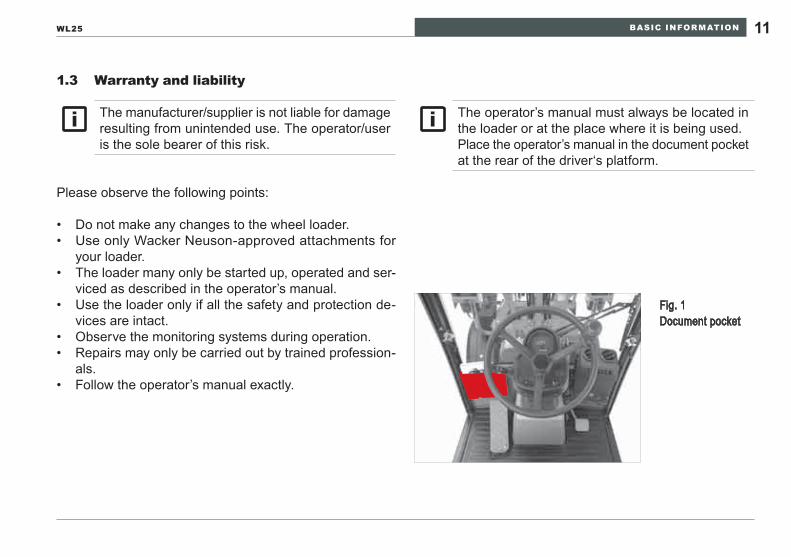
The operator’s manual must always be located in the loader or at the place where it is being used.Place the operator’s manual in the document pocket at the rear of the driver‘s platform.
Fig. 1 Document pocket
BASIC INFORMATION12
The loader is used to dislodge and load material by moving the loader forward, taking into account the safety instructions / regulations and time periods listed by Wacker Neuson in the operator’s manual. One work cycle consists of picking up, lifting, transporting and unloading the material.
Similar uses of the loader with alternative attachments which do not change the safety requirements for the loader but modify the way in which it is used are only acceptable when attachments that have been expressly approved by Wacker Neuson are employed. Special conditions apply if you use additional Wacker Neuson attachments.
The intended operation is described in this Operator’s Manual. The instructions describe how to operate, main-tain, inspect and adjust the wheel loader safely. The repair manual provides additional instruction for safely diagnosing malfunctions and repairing the wheel loader to maintain service and performance levels.
Intended use1.4
The loader has been built according to applicable standards and regulations. Operation by inexperienced persons, or in an unintended manner, can result in hazards that can lead to personal risk and subsequent harm to the operator and persons in the operating area of the wheel loader. Improper use can damage the wheel loader as well as property in the vicinity of operation.
Read and understand the operating instructions in this Man-ual before operating this wheel loader. Before performing production work, the operator should find a remote site to become familiar with the controls and machine response. The machine shall be in serviceable condition before at-tempting to use it as described in the operating instructions. If the wheel loader is determined not to be in serviceable condition, notify the site or machine supervisor to have it repaired before use.
Unintended use can endanger the lives of operating personnel or other persons and cause injuries or extensive material damage.

BASIC INFORMATION 13WL25
The wheel loader shall not be employed for any of the fol-lowing work activities:
lifting or transporting people• using it as a working platform• using it to lift or transport loads without providing work • equipment for itpulling trailer loads• operating after the machine has received unauthorized • repairsoperating with unauthorized modifications•
BASIC SAFETY INSTRUCTIONS14
BASIC SAFETY INSTRUCTIONS2
Use the loader and attachments only as intended and • in serviceable condition.Observe the operating instructions described in this • Operator’s Manual and all applicable work site safety regulations.Observe the permissible payloads.• Wheel Loaders may only be used on suitable terrain.•
This Wheel Loader is equipped with a Starter Lock / Drive Lock which must be kept operational.
NOTICEShould the loader be used by a private person or by other persons who are both operators and users, then they must also observe all safety instructions. Observance of the organizational safety instruc-tions and the safety instructions relating to the se-lection and qualification of personnel in particular are basic duties. If there are no trained personnel for the various tasks, the operator/user must at-tend to this. In case you require training sessions or instruction/training personnel, Wacker Service and our agents will be happy to help you.
BASIC SAFETY INSTRUCTIONS 15WL25
Organizational measures2.1
The following safety instructions are directed at the operator / user of the loader.
Always keep the operator’s manual in the tray provided • for it.As a supplement to the operator’s manual, universally • valid legal and other binding regulations relating to road traffic, compulsory coverage, accident prevention and environmental protection must be observed, and users must be instructed to observe them. This applies in par-ticular to the maximum speed, depending on the model and the permissible total weight of the loader.If required, instruct that personal protective equipment be • worn. This applies particularly to the handling of harmful substances at the location of use.Supplement the operator’s manual with instructions, • including supervisory and reporting requirements, taking into account differences between various companies, e.g. with regard to the organization of work, work pro-cesses or personnel used.
Personnel who have been assigned to operate the loader • must have read the operator’s manual before operating the wheel loader especially the chapter Basic Safety Instructions.Observe all safety messages on the loader and in the • operator’s manual.Make sure that all safety messages on the machine • are legible.If the loader becomes unserviceable, stop operating and • inform the supervisor that the wheel loader is not func-tioning normally. Alternately, contact a trained technician to diagnose and correct the condition before resuming operation.No modifications shall be made to the wheel loader. • Contact your Wacker Neuson dealer for specific advice regarding the use of the wheel loader and approved attachments.
BASIC SAFETY INSTRUCTIONS16
If worn or damaged parts need replacement, use only • Wacker Neuson replacement parts to ensure optimum performance and safety.Inspect hydraulic hoses and fittings prior to the start of • each work shift. Correct any observed leaks or abrasion issues before operating the machine. Extended envi-ronmental exposure can cause undetectable damage. Replace hose assemblies periodically as advised in the maintenance schedule.Thoroughly inspect the wheel loader before each op-• erating shift.The Wheel Loader Repair Manual describes the special • tools, diagnosis techniques, repair sequence proce-dures, lifting and supporting devices needed to repair this machine. To avoid unnecessary hazards and possible damage to the Wheel Loader, do not attempt to repair this machine without complying with the instructions in the Repair Manual.
Make the location and means of operation of the fire • extinguishers known, and consider the options for fire detection and fighting.A Falling Object Protection System (FOPS) is available • for the Wheel Loader Operator Protection System. OSHA and MSHA require this protection when operating with overhead hazards. Contact your Wacker Neuson dealer for advice and availability of a certified FOPS.
BASIC SAFETY INSTRUCTIONS 17WL25
Selection and qualification of personnel / basic duties2.2
Personnel being trained, educated, instructed or partici-• pating in a general training program may only work on or with the machine under constant supervision of an experienced, authorized supervisor.Work on the machine‘s electrical equipment may only be • carried out by an electrician or by trained persons under the direction and supervision of an electrician.Work on the chassis, brakes and steering system may • only be performed by trained, specialized personnel.Only trained, specialized personnel with specific knowl-• edge of and experience in hydraulics may work on hy-draulic units.
The operator of the wheel loader must be qualified to • operate the machine through demonstration of com-prehension of the operating instructions. No one shall operate the wheel loader if impaired due to intoxication or drug reaction.Diagnosis and repair of the wheel loader shall be per-• formed by trained competent technicians unimpaired by intoxication or drug reaction.Prohibit unauthorized and untrained people from access • to the starting key and operation of the wheel loader.The wheel loader operator is responsible for visually • monitoring the work area of the wheel loader and pre-venting anyone from entering the area without permis-sion. If a person enters the area while the wheel loader is in operation, the operator shall stop the wheel loader and instruct the person to leave the work area until the wheel loader has been stopped in a safe mode. The person may then approach the machine in full view of the operator.
BASIC SAFETY INSTRUCTIONS18
Safety instructions for certain operating phases2.3
If the wheel loader does not respond as expected to the • operator command or exhibits a malfunction, stop the machine, contact the supervisor and restore the machine to serviceable condition before resuming operation.Start and operate the loader only from the operator’s • seat.When switching on and off, observe the indicator dis-• plays in accordance with the operator’s manual.Make sure no one is located in the operating area of the • loader before starting the engine.After starting the engine and confirming that the indi-• cators are responding correctly, activate the steering, brakes, lights, signals and loader/accessory functions to confirm that these devices are responding correctly to the control command.To avoid damage to the wheel loader, position the loader • bucket or accessories before moving the machine. Re-confirm that there are no people in the work or travel area before moving the machine.
The safety instructions are directed at all persons involved in work on or with the loader.
Safety instructions for normal operation2.3.1
Refrain from any measures that could put safety into • question. Before starting work, familiarize yourself with the working • environment in which you will be using the loader. The working environment includes, for example, obstacles in the working and traffic area, the bearing capacity of the ground and the necessary safeguarding of the location to allow it to be used as a public traffic area. Take precautions to ensure that the loader is operated • only in a safe, serviceable state.Only operate the loader if all the protection devices and • safety devices, e.g. detachable protection devices, sound absorbers and exhaust equipment, are serviceable and operational.Check the loader at least once a day for visible de-• fects.
BASIC SAFETY INSTRUCTIONS 19WL25
When driving on public roads, lanes and squares, ob-• serve the valid road traffic regulations and put the loader into a condition permissible for the road beforehand.As a matter of principle, turn on the lights when trav-• eling on public roads to increase awareness for road traffic..When driving through underpasses, gates, bridges, tun-• nels, overhead lines, etc., always make sure that you have enough clearance above and on both sides and a sufficient safety margin.Always keep sufficient distance away from excavations, • embankments and the edges of piled up material.Refrain from any method of operation that could ad-• versely affect the loader‘s stability. This also includes the duty to pass on information regarding the approved carrying capacity (=payload) for the relevant loader at-tachments. (carrying capacity / approved payload are specified in the operator’s manual)
Do not drive transversely on slopes; always keep work • equipment and load near the ground, especially when driving down slopes.When driving down a slope, always adjust your driv-• ing speed to take account of the respective conditions. Always reduce your speed before reaching a downhill slope, and not after you have reached it.The load must be located on the uphill side during driv-• ing on downhill or uphill slopes.As a matter of principle, always secure the loader from • accidentally rolling away and against unauthorized use. Turn off the engine, put on the parking brake, lower the work equipment, remove the starting key and, if neces-sary, employ a wheel chock.
BASIC SAFETY INSTRUCTIONS20
Safety instructions for other operating modes2.3.2
These safety instructions refer to special tasks relating to the use of the loader and servicing tasks - as well as emergency maintenance during operation or work concerning disposal of the auxiliary and operating materials.
The Operator’s Manual provides adjustment, mainte-• nance and inspection information and schedules in subsequent sections. This information is essential to ensuring peak performance satisfaction and safety over the life of the wheel loader.This Operator’s Manual provides routine adjustment • and maintenance procedures in addition to operating instructions. Diagnosis and repair of the wheel loader requires special skill, training and tools. Your Wacker Neuson dealer has the trained technicians to perform such work safely and effectively.Maintenance and repair work shall be performed by • operators and technicians trained and knowledgable of the wheel loader function and attachments.
Do not attempt to perform maintenance or repair on the • wheel loader until the machine and engine is stopped and all attachments are in a stable position. Do not attempt to perform maintenance or repair work on hot surfaces or components of the machine. Read and understand the procedure for maintenance and repair in the Operator’s and Repair Manuals for this wheel loader.Secure the maintenance area, allowing as large a space • as required.If the loader is being completely shut off during servicing • and maintenance work, please observe the following (see the chapter »Securing the Loader«):
Secure the loader from being accidentally turned back -on by removing the starting key.Attach a warning note to indicate that the loader is be- -ing worked on.Only carry out servicing and maintenance work if the -loader is parked on an even, hard surface and secured from rolling away and articulating at the steering swivel point..Before performing work with the loader arms raised, -install the support provided to prevent the loader arms from lowering suddenly and inadvertently.This device shall conform to ISO 10533. -
BASIC SAFETY INSTRUCTIONS 21WL25
Use lifting devices to raise and support parts and as-• semblies exceeding 10 kg (22 lbs) weight during repair and replacement activity. Use only OSHA approved devices to perform the lifting operation and verify that the lifting devices are in serviceable condition.The use of a crane to lift heavy assemblies or compo-• nents requires that the operator is certified by OSHA. The person attaching the load and signaling the operator must be trained in proper techniques as well as voice and hand signals to instruct the crane operator.For assembly above head height, use only climbing aids • and working platforms which are intended for this pur-pose, or which are safe for use in this situation. Do not use machine parts as climbing aids. Keep all handles, steps, pedestals, platforms and ladders free of dirt, snow and ice.
Clean the entire loader, especially the connections • and threaded connections, with oil, fuel or care prod-ucts when beginning maintenance and servicing work. Use lint-free cleaning rags and no aggressive cleaning agents.Before cleaning the loader with water or by steam jet • (high-pressure cleaner) or with other cleaning agents, cover up / seal off all the openings into which water, steam and cleaning agents are not permitted to enter. Electrical components, inlets and outlets for the engine‘s combustion air and tank openings are particularly at risk. Completely remove the covers / seals after you have finished cleaning.Before restarting, retighten any threaded connections • loosened during servicing and repairs, in particular for oil or fuel lines. When carrying out maintenance and servicing work, check all the lines and threaded con-nections for leaks and tight fit.

BASIC SAFETY INSTRUCTIONS22
Should it be necessary to remove safety devices during • setup, servicing or repairs, reinstall and check the safety devices immediately after finishing the work and verify that the devices perform correctly.Replace the ROPS or FOPS structure if it is perma-• nently deflected, a member is deformed, it has become corroded, and/or it has been modified. If the mount-ing structure, base, or mounting hardware is damaged, consult your Wacker Neuson dealer for assistance. Do not attempt to repair, straighten or reuse a damaged ROPS or FOPS.Responsibly dispose of the unwanted materials and • fluids resulting from the repair. Hazardous material shall be disposed in a hazardous material container(s). Parts and assemblies can be recycled.
WARNINGNever use the machine without the ROPS/FOPS properly installed.
Do not drill, weld, straighten, or bend the ROPS ►/ FOPS protective structures.Allow only trained authorized personnel to install ►new ROPS / FOPS structures.
ROPS / FOPS - protective structures
BASIC SAFETY INSTRUCTIONS 23WL25
Safety instructions for particular hazards2.4
Forklift attachment2.4.1
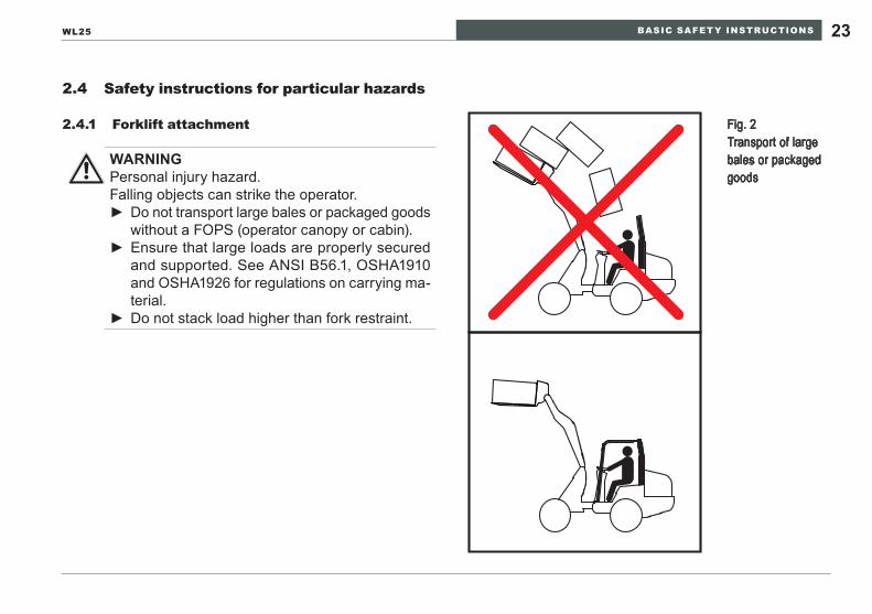
WARNINGPersonal injury hazard.Falling objects can strike the operator.
Do not transport large bales or packaged goods ►without a FOPS (operator canopy or cabin).Ensure that large loads are properly secured ►and supported. See ANSI B56.1, OSHA1910 and OSHA1926 for regulations on carrying ma-terial.Do not stack load higher than fork restraint. ►
Fig. 2 Transport of large bales or packaged goods
BASIC SAFETY INSTRUCTIONS24
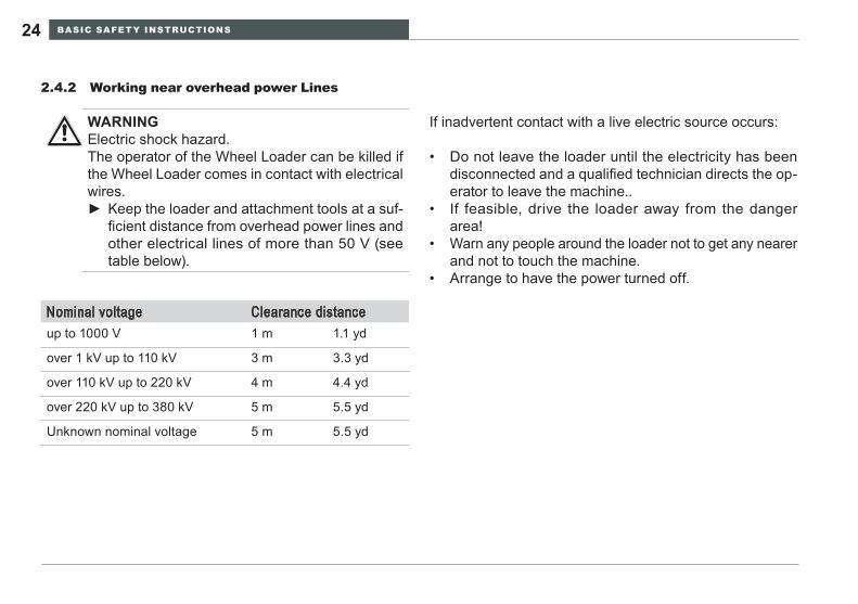
WARNINGElectric shock hazard.The operator of the Wheel Loader can be killed if the Wheel Loader comes in contact with electrical wires.
Keep the loader and attachment tools at a suf- ►ficient distance from overhead power lines and other electrical lines of more than 50 V (see table below).
If inadvertent contact with a live electric source occurs:
Do not leave the loader until the electricity has been • disconnected and a qualified technician directs the op-erator to leave the machine..If feasible, drive the loader away from the danger • area!Warn any people around the loader not to get any nearer • and not to touch the machine.Arrange to have the power turned off.•
Working near overhead power Lines2.4.2
Nominal voltage Clearance distanceup to 1000 V 1 m 1.1 yd
over 1 kV up to 110 kV 3 m 3.3 yd
over 110 kV up to 220 kV 4 m 4.4 yd
over 220 kV up to 380 kV 5 m 5.5 yd
Unknown nominal voltage 5 m 5.5 yd
BASIC SAFETY INSTRUCTIONS 25WL25
Electrical power2.4.3
Regularly check the loader‘s electrical equipment. De-• fects, such as loose plug connections or cables with burnt insulation, shall be replaced before resuming op-eration.If an electrical malfunction is discovered, stop the wheel • loader in a safe location, lower the loader arms and at-tachment to the ground and stop the engine. Contact the supervisor for diagnosis and repair by a qualified technician before resuming operation.Replacement fuses shall be of the same type and capac-• ity as specified by the manufacturer in the Operator’s and Repair Manuals. Do not attempt to bypass a fused system to resume operation.
Flying sparks / fire danger2.4.4
WARNINGFire hazard.Sparks from the exhaust, or electrical equipment, or hot machine parts can ignite explosions and fires.
Do not work in enclosed spaces where flam- ►mable materials, explosive vapors, or combus-tible dust are found.Stay clear of flammable materials such as hay ►and straw.Park the Wheel Loader only in areas free of ►flammable materials.
BASIC SAFETY INSTRUCTIONS26
Gas, dust, steam, smoke2.4.5
Diesel engine exhaust emissions are toxic in concen-• trated amounts. Do not operate the wheel loader in en-closed spaces or inadequately ventilated spaces.Determine and follow regulations regarding safe opera-• tion at the specific work site.
Do not operate the wheel loader near open flames. -Do not perform welding repairs in explosive atmo- -spheres.Do not weld fuel tanks or fuel system components. -Do not perform any welding operation unless qualified -to do so.
Wear appropriate personal protective equipment (breath-• ing filter, protective suit) for protection against specific dangers, e.g. poisonous gases, corrosive steam, poison-ous (i.e. containing toxins) surroundings, etc.
Hydraulics, pneumatics2.4.6
When detected, oil leaks shall be repaired to avoid:• environmental hazards -fire hazards -slip hazards -explosion hazards -personal injury hazards. -
Do not attempt to repair a hydraulic system or component • until the hydraulic pressure has been relieved. Relieve the pressure by activating controls as advised in this Operator’s Manual or the Repair Manual.Replace hydraulic lines and fittings with original equip-• ment parts from your Wacker Neuson dealer to assure original performance and safety. The reinstalled hy-draulic line routing and attachment shall conform to the original routing. Confirm that the replacement routing is not interfering with other parts, chafing across sharp surfaces or resting on or near hot surfaces.
BASIC SAFETY INSTRUCTIONS 27WL25
NOTICEUse the appropriate fuel for climate temperature ranges to avoid engine stoppage from fuel gell-ing.
Noise2.4.8
All the loader‘s sound-proofing devices must be in their • protection position during operation.If necessary, the driver must wear personal hearing • protection.
Oils, grease and other chemical substances2.4.9
Observe the valid safety regulations for the respective • product when handling oil, grease and other chemical substances.Do not service the wheel loader immediately after op-• eration. Wait until hot surfaces have cooled and can be touched comfortably.Smoking and open flames are prohibited during fueling. • Danger of fire or explosion!
Tip-overs2.4.7
WARNINGPersonal injury hazard.Falling Loader can strike the operator.
Do not operate the wheel loader without fasten- ►ing the seat belt.Keep the loader lift arms and attachment as low ►as practical when traveling.
If the machine tips over, or in the event of an ex-treme slope condition, take the following steps to avoid engine damage:
Stop the engine as quickly as practical to avoid ►damage from lubrication starvation.Do not operate the engine or machine after an ►incident until a technician has inspected and corrected any damage resulting from the in-cident.
BASIC SAFETY INSTRUCTIONS28
Transporting and towing / restarting2.5
Instructions are provided in this operator’s manual for • towing, loading and transporting the wheel loader safely without machine damage.The towing machine shall be capable of towing the wheel • loader.The loading and transport equipment shall be appropri-• ate to safely complete the sequence of operation. If the wheel loader is to be lifted by a crane device, consult the machine specifications to select the correct crane capacity and OSHA lifting devices to safely complete the lifting operation.Only restart the loader according to the operator’s • manual.See Chapter 6 for complete transporting and towing • instructions.
Final decommissioning / dismantling2.6
Drain and dispose of all fluids in suitable containers and • dispose of the fluids in an environmentally responsible manner. Do not dispose in sewers, streams, lakes or on the ground.Remove the battery and dispose of it at an authorized • recycling center. Remove the starting motor to disable the engine.Dismantle and recycle the components according to the • material instructions on the individual parts. Tires and rubber based parts can be recycled separately.
BASIC SAFETY INSTRUCTIONS 29WL25
15
3
6
8 9 10
2 14
7
1511 12
13
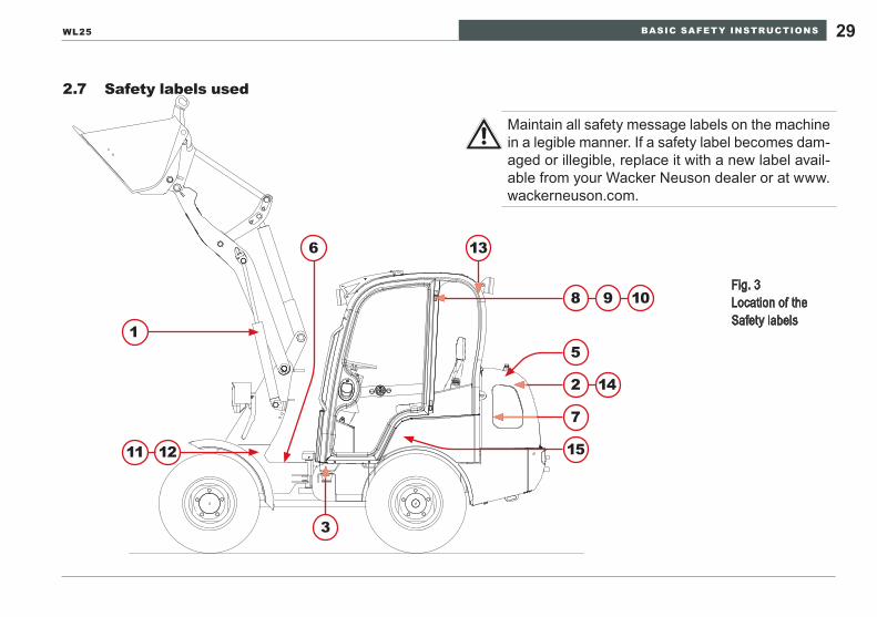
Fig. 3 Location of the Safety labels
Safety labels used2.7
Maintain all safety message labels on the machine in a legible manner. If a safety label becomes dam-aged or illegible, replace it with a new label avail-able from your Wacker Neuson dealer or at www.wackerneuson.com.
BASIC SAFETY INSTRUCTIONS30
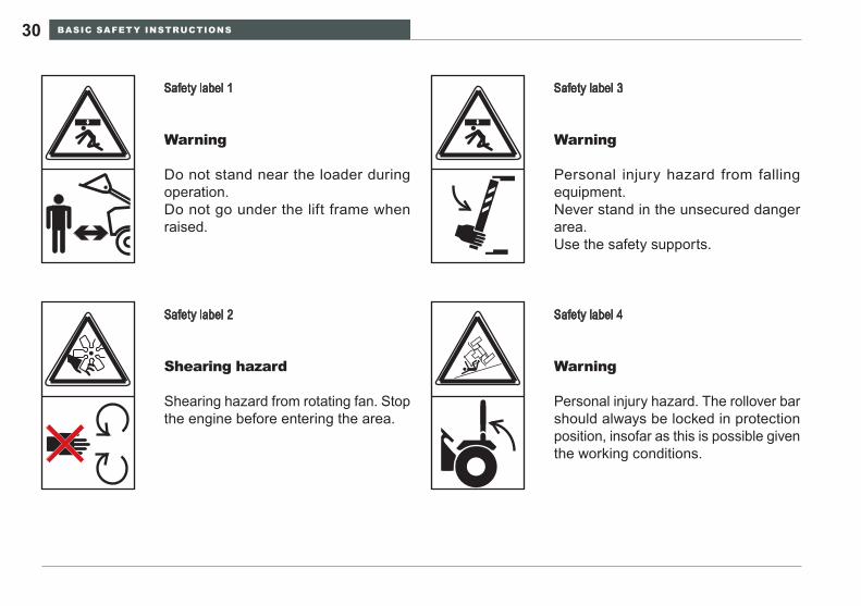
Safety label 3
Warning
Personal injury hazard from falling equipment.Never stand in the unsecured danger area.Use the safety supports.
Safety label 1
Warning
Do not stand near the loader during operation.Do not go under the lift frame when raised.
Safety label 2
Shearing hazard
Shearing hazard from rotating fan. Stop the engine before entering the area.
Safety label 4
Warning
Personal injury hazard. The rollover bar should always be locked in protection position, insofar as this is possible given the working conditions.
BASIC SAFETY INSTRUCTIONS 31WL25
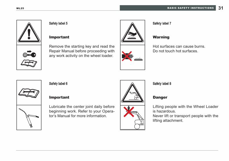
Safety label 5
Important
Remove the starting key and read the Repair Manual before proceeding with any work activity on the wheel loader.
Safety label 6
Important
Lubricate the center joint daily before beginning work. Refer to your Opera-tor’s Manual for more information.
Safety label 7
Warning
Hot surfaces can cause burns.Do not touch hot surfaces.
Safety label 8
Danger
Lifting people with the Wheel Loader is hazardous.Never lift or transport people with the lifting attachment.
BASIC SAFETY INSTRUCTIONS32
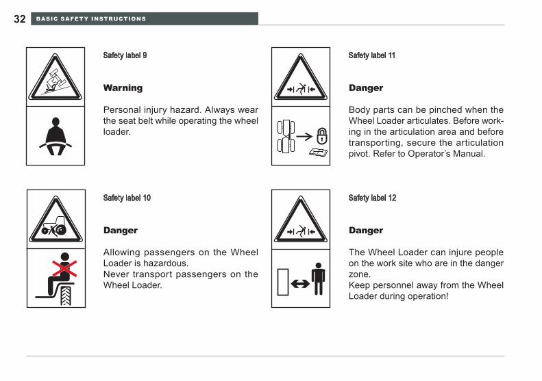
Safety label 12
Danger
The Wheel Loader can injure people on the work site who are in the danger zone.Keep personnel away from the Wheel Loader during operation!
Safety label 11
Danger
Body parts can be pinched when the Wheel Loader articulates. Before work-ing in the articulation area and before transporting, secure the articulation pivot. Refer to Operator’s Manual.
Safety label 10
Danger
Allowing passengers on the Wheel Loader is hazardous.Never transport passengers on the Wheel Loader.
Safety label 9
Warning
Personal injury hazard. Always wear the seat belt while operating the wheel loader.
BASIC SAFETY INSTRUCTIONS 33WL25
Vor dem Kippen der Kabine beide Türen schließen!
Voor
u de K
abine
kante
let, b
eide d
euren
sluit
en! Avant de basculer la cabine, verrouiller les deux portes!
Close bothdoors before
tilting the cab!
!
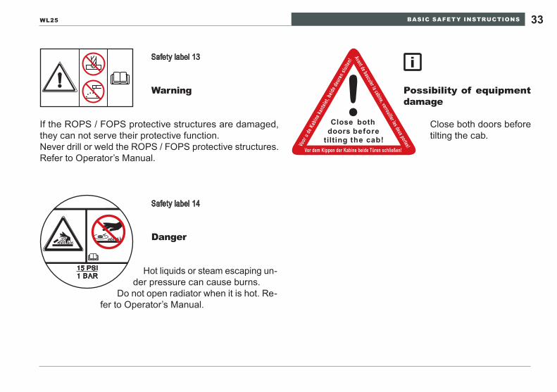
Safety label 14
Danger
Safety label 13
Warning Possibility of equipment damage
15 PSI1 BAR
If the ROPS / FOPS protective structures are damaged, they can not serve their protective function.Never drill or weld the ROPS / FOPS protective structures. Refer to Operator’s Manual.
Hot liquids or steam escaping un-der pressure can cause burns.
Do not open radiator when it is hot. Re-fer to Operator’s Manual.
Close both doors before tilting the cab.
BASIC SAFETY INSTRUCTIONS34
Safety devices2.8
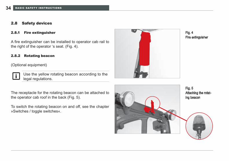
Fire extinguisher2.8.1
A fire extinguisher can be installed to operator cab rail to the right of the operator ‘s seat. (Fig. 4).
Rotating beacon2.8.2
(Optional equipment)
Fig. 4 Fire extinguisher
Fig. 5 Attaching the rotat-ing beacon
The receptacle for the rotating beacon can be attached to the operator cab roof in the back (Fig. 5).
To switch the rotating beacon on and off, see the chapter »Switches / toggle switches«.
Use the yellow rotating beacon according to the legal regulations.
BASIC SAFETY INSTRUCTIONS 35WL25
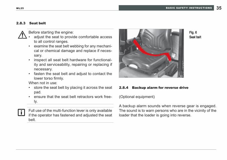
Seat belt2.8.3
Before starting the engine:adjust the seat to provide comfortable access • to all control ranges.examine the seat belt webbing for any mechani-• cal or chemical damage and replace if neces-sary.inspect all seat belt hardware for functional-• ity and serviceability, repairing or replacing if necessary.fasten the seat belt and adjust to contact the • lower torso firmly.
When not in use:store the seat belt by placing it across the seat • pad.ensure that the seat belt retractors work free-• ly.
Full use of the multi-function lever is only available if the operator has fastened and adjusted the seat belt.
Backup alarm for reverse drive2.8.4
(Optional equipment)
A backup alarm sounds when reverse gear is engaged. The sound is to warn persons who are in the vicinity of the loader that the loader is going into reverse.
Fig. 6 Seat belt
BASIC SAFETY INSTRUCTIONS36
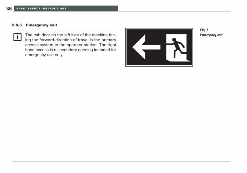
Emergency exit2.8.5 Fig. 7
Emergency exitThe cab door on the left side of the machine fac-ing the forward direction of travel is the primary access system to the operator station. The right hand access is a secondary opening intended for emergency use only.
BASIC SAFETY INSTRUCTIONS 37WL25
Battery disconnect switch2.8.6
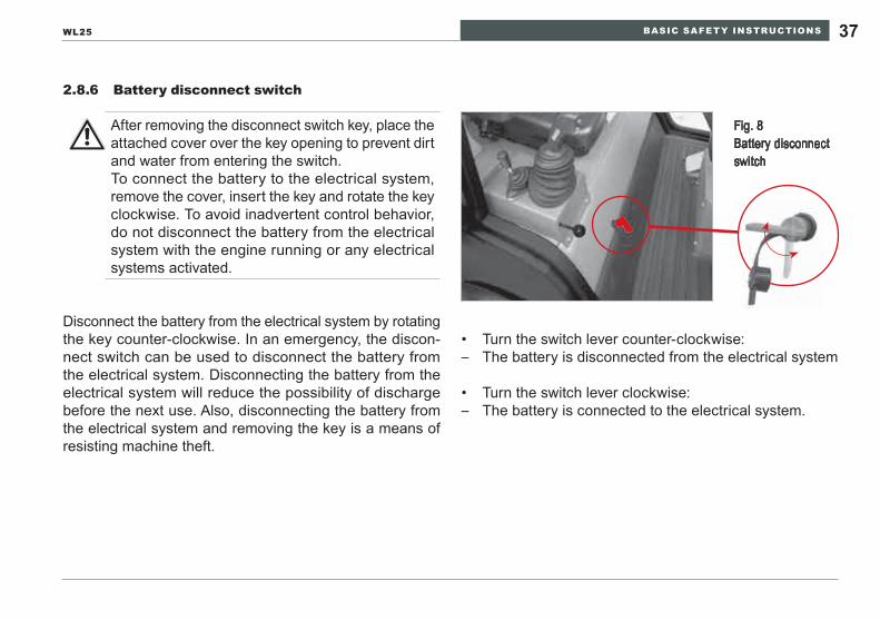
Disconnect the battery from the electrical system by rotating the key counter-clockwise. In an emergency, the discon-nect switch can be used to disconnect the battery from the electrical system. Disconnecting the battery from the electrical system will reduce the possibility of discharge before the next use. Also, disconnecting the battery from the electrical system and removing the key is a means of resisting machine theft.
Turn the switch lever counter-clockwise:• The battery is disconnected from the electrical system –
Turn the switch lever clockwise:• The battery is connected to the electrical system. –
After removing the disconnect switch key, place the attached cover over the key opening to prevent dirt and water from entering the switch.To connect the battery to the electrical system, remove the cover, insert the key and rotate the key clockwise. To avoid inadvertent control behavior, do not disconnect the battery from the electrical system with the engine running or any electrical systems activated.
Fig. 8 Battery disconnect switch
BASIC SAFETY INSTRUCTIONS38
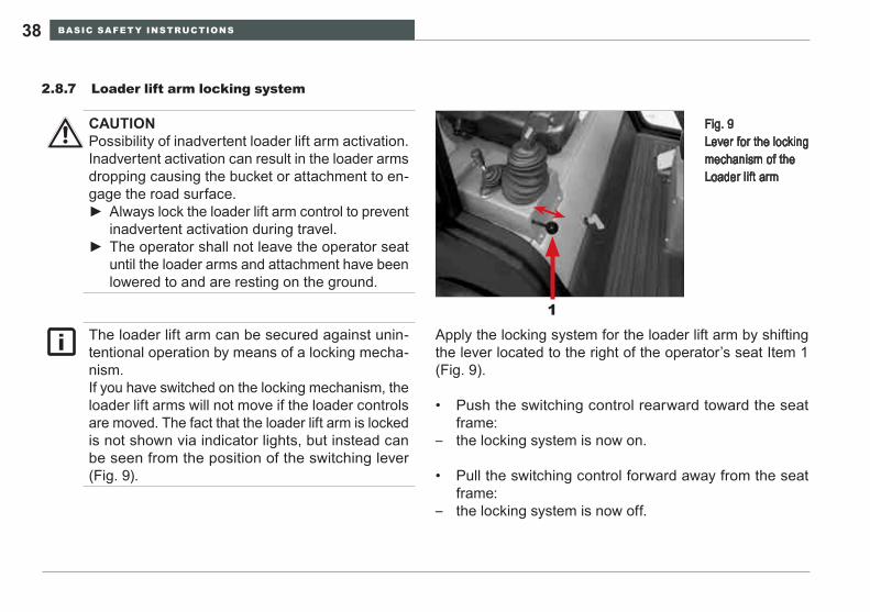
Loader lift arm locking system2.8.7
Apply the locking system for the loader lift arm by shifting the lever located to the right of the operator’s seat Item 1 (Fig. 9).
Push the switching control rearward toward the seat • frame:the locking system is now on. –
Pull the switching control forward away from the seat • frame:the locking system is now off. –
Fig. 9 Lever for the locking mechanism of the Loader lift arm
1
CAUTIONPossibility of inadvertent loader lift arm activation. Inadvertent activation can result in the loader arms dropping causing the bucket or attachment to en-gage the road surface.
Always lock the loader lift arm control to prevent ►inadvertent activation during travel.The operator shall not leave the operator seat ►until the loader arms and attachment have been lowered to and are resting on the ground.
The loader lift arm can be secured against unin-tentional operation by means of a locking mecha-nism.If you have switched on the locking mechanism, the loader lift arms will not move if the loader controls are moved. The fact that the loader lift arm is locked is not shown via indicator lights, but instead can be seen from the position of the switching lever (Fig. 9).
TECHNICAL DATA 39WL25
TECHNICAL DATA3
Technical description3.1
The loader consists of the vehicle frame, the drive and the axles. The vehicle frame contains all the drive and con-trol units for the standard configuration. The vehicle frame consists of the front carriage with the lift frame, and the rear carriage, in which the drive unit is situated. They are connected by an articulated swivel joint.
Drive
The loader is driven by a diesel engine, which powers the steering and working hydraulics and the driving hydrau-lics.
The driving hydraulics power the transfer case, which trans-fers the force to the rear axle, and to the front axle (via the drive shaft).
The axles are designed as rigid axles.
Brakes
The drive also functions as the service brake. It acts on the front and rear axles. The brake is activated via the braking-inching pedal. Furthermore, the braking-inching pedal is used to activate the hub brake on the differential. The park-ing brake also operates mechanically on this hub brake.
Steering
The fully hydraulic articulated swivel steering system oper-ates via a dual action cylinder.

TECHNICAL DATA40
Hydraulics
The loader has two hydraulic systems supplied by a hy-draulic fluid reservoir:
- hydrostatic drive
- steering and working hydraulics
The hydrostatic drive consists of an axial piston variable displacement pump, which drives an axial piston motor. The axial piston variable displacement pump is rigid coupled directly to the diesel engine, while the axial piston motor is directly coupled to the transfer case.
Displacement is automatic and continuous, but depends on speed and load. The travel speed depends on the engine speed and the machine load. Operating speed is set by the accelerator pedal position, engine speed and torque demand of the loading operation. Depending on load, the variable displacement pump automatically adjusts pump displacement to balance torque and speed requirements within the power capability of the diesel engine. Since the
input power is limited to the diesel engine output, increased demands from traversing a grade or loading the bucket will result in speed reduction which increases the torque to meet the performance demand. This adjustment control allows the entire range of performance to be utilized optimally. Actuating the inching pedal (inching delay, left pedal) in is an override control that can reduce wheel loader speed as operation demands. Depressing the pedal to the full range will stop the travel motion of the wheel loader. The inch-ing pedal permits an infinite number of control positions. The inching pedal provides the service brake function by destroking the pump until no fluid is transmitted between the pump and motor.
A gear hydraulic pump supplies the steering and working hydraulics with oil. The gear pump is rigid coupled to the drive‘s variable displacement pump. Pump flow output is directly proportional to the diesel engine speed.
The hydraulic system is equipped with relief valves, filters and oil coolers.

TECHNICAL DATA 41WL25
Electrical system
The electrical system operates at 12 volts and the electrical circuits are protected by fuses to prevent overload damage to the system and its components.
Equipment
The loading equipment consists of the lift frame with an integrated mechanical or hydraulic quick-change recep-tacle, lifting and tipping cylinders and the appropriate at-tachments.
The loader is equipped with a rollover protective structure (ROPS).
Loader data3.2
Engine4-cylinder Perkins diesel engine
Output 24,6 kW / 34 hp at 2800 rpmSAE rating according to ISO9249
Type 404 D – 15 water-cooled
Capacity 1508 cm³ (92 inch³)
Drive (driving speed)1. gear 0 – 7 km/h 0 – 4.35 mph
2. gear 0 – 20 km/h 0 – 12.43 mph
SteeringFully hydraulic center-pivot steering
Rotating angle 12°
Turn angle 45°
Electrical systemWorking voltage 12 volts
Battery 77 Ah
TECHNICAL DATA42
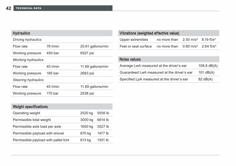
Weight specif icationsOperating weight 2520 kg 5556 lb
Permissible total weight 3000 kg 6614 lb
Permissible axle load per axle 1600 kg 3527 lb
Permissible payload with shovel 670 kg 1477 lb
Permissible payload with pallet fork 613 kg 1351 lb
HydraulicsDriving hydraulics
Flow rate 78 l/min 20.61 gallons/min
Working pressure 450 bar 6527 psi
Working hydraulics
Flow rate 45 l/min 11.89 gallons/min
Working pressure 185 bar 2683 psi
Steering hydraulics
Flow rate 45 l/min 11.89 gallons/min
Working pressure 175 bar 2538 psi
Noise valuesAverage LwA measured at the driver‘s ear 108,8 dB(A)
Guaranteed LwA measured at the driver‘s ear 101 dB(A)
Specified LpA measured at the driver‘s ear 82 dB(A)
Vibrations (weighted ef fective value)Upper extremities no more than 2.50 m/s² 8.19 ft/s²
Feet or seat surface no more than 0.80 m/s² 2.64 ft/s²
TECHNICAL DATA 43WL25
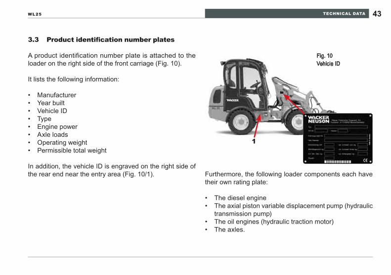
Product identification number plates3.3
A product identification number plate is attached to the loader on the right side of the front carriage (Fig. 10).
It lists the following information:
Manufacturer• Year built• Vehicle ID• Type• Engine power• Axle loads• Operating weight• Permissible total weight•
In addition, the vehicle ID is engraved on the right side of the rear end near the entry area (Fig. 10/1). Furthermore, the following loader components each have
their own rating plate:
The diesel engine• The axial piston variable displacement pump (hydraulic • transmission pump)The oil engines (hydraulic traction motor)• The axles.•
Fig. 10 Vehicle ID
1
TECHNICAL DATA44
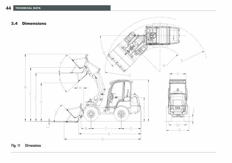
Dimensions3.4
DimensionsFig. 11
TECHNICAL DATA 45WL25
*In the event of deviating tires or reversed wheel rims the dimensions will change
Dimensions with 10x16,5 EM tires
Item Designation ValueA Overall length with standard
shovel 4087 mm 160.91 inch
A‘ Overall length without shovel 3302 mm 130.00 inchB Axle center to shovel pivot-
point 532 mm 20.94 inch
C Wheelbase 1612 mm 63.46 inchD Rear overhang 1045 mm 41.14 inchE Overhead loading height* 2573 mm 101.30 inchF Max. height of shovel pivot
point* 2862 mm 112.68 inch
G Height of seat* 1259 mm 49.57 inchH Max. dumping height* 2047 mm 80.59 inchI Scraping depth* 50 mm 1.97 inchK Reach at H* 337 mm 13.27 inchL Height to top of cab* 2208 mm 86.93 inch
Item Designation ValueM Total working height* 3582 mm 141.02 inchN Max. dumping angle at max.
lift height 42°
O Reverse roll angle on ground 46°P Reverse roll angle at max. lift 48°Q Inside turning radius* 1330 mm 52.36 inchR Overall width* 1210 mm 47.64 inchS Radius at outer edge* 2590 mm 101.97 inchT Ground clearance* 250 mm 9.84 inchU Turn angle 45°V Width across cab 870 mm 34.25 inchW Track width* 940 mm 37.01 inchZ Maximum turning radius
(depends on shovel width) 2912 mm 114.65 inch
DesCRIpTION Of The INDICATOR, WARNING AND CONTROl elemeNTs46
DESCRIPTION OF THE INDICATOR, WARNING AND CONTROL ELEMENTS4
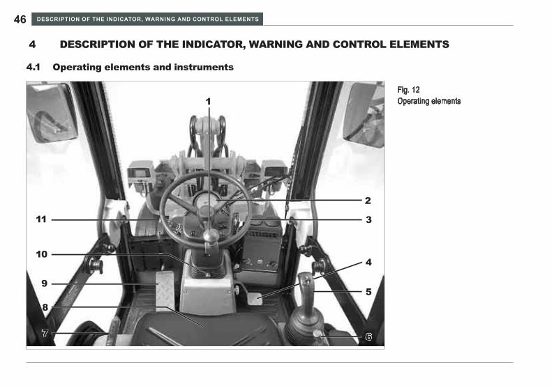
Operating elements and instruments4.1
Fig. 12 Operating elements1
2
3
4
5
67
8
9
10
11
DesCRIpTION Of The INDICATOR, WARNING AND CONTROl elemeNTs 47WL25
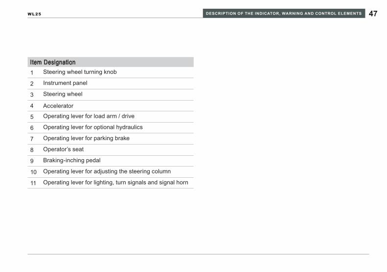
Item Designation1 Steering wheel turning knob
2 Instrument panel
3 Steering wheel
4 Accelerator
5 Operating lever for load arm / drive
6 Operating lever for optional hydraulics
7 Operating lever for parking brake
8 Operator’s seat
9 Braking-inching pedal
10 Operating lever for adjusting the steering column
11 Operating lever for lighting, turn signals and signal horn
DesCRIpTION Of The INDICATOR, WARNING AND CONTROl elemeNTs48
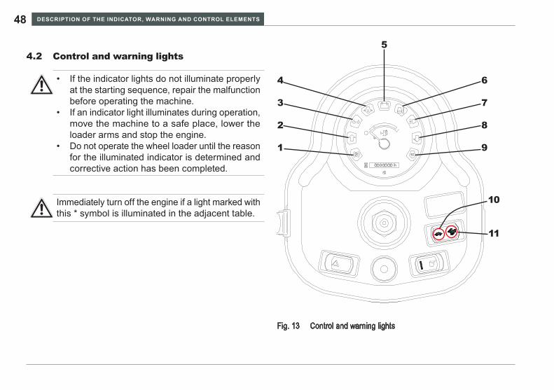
Control and warning lights4.2
Control and warning lightsFig. 13
1
2
3
4
5
6
7
8
9
10
11
If the indicator lights do not illuminate properly • at the starting sequence, repair the malfunction before operating the machine.If an indicator light illuminates during operation, • move the machine to a safe place, lower the loader arms and stop the engine.Do not operate the wheel loader until the reason • for the illuminated indicator is determined and corrective action has been completed.
Immediately turn off the engine if a light marked with this * symbol is illuminated in the adjacent table.
DesCRIpTION Of The INDICATOR, WARNING AND CONTROl elemeNTs 49WL25
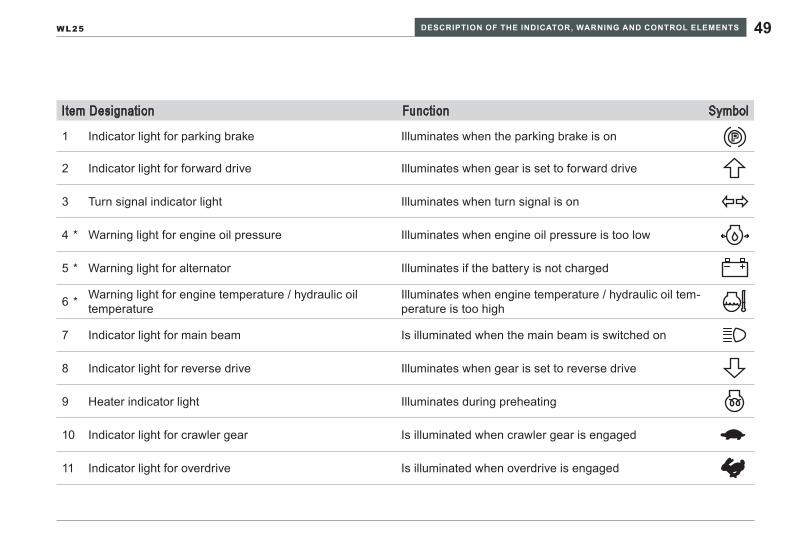
Item Designation Function Symbol
1 Indicator light for parking brake Illuminates when the parking brake is on P
2 Indicator light for forward drive Illuminates when gear is set to forward drive
3 Turn signal indicator light Illuminates when turn signal is on
*4 Warning light for engine oil pressure Illuminates when engine oil pressure is too low
*5 Warning light for alternator Illuminates if the battery is not charged
*6 Warning light for engine temperature / hydraulic oil temperature
Illuminates when engine temperature / hydraulic oil tem-perature is too high
7 Indicator light for main beam Is illuminated when the main beam is switched on
8 Indicator light for reverse drive Illuminates when gear is set to reverse drive
9 Heater indicator light Illuminates during preheating
10 Indicator light for crawler gear Is illuminated when crawler gear is engaged
11 Indicator light for overdrive Is illuminated when overdrive is engaged
DesCRIpTION Of The INDICATOR, WARNING AND CONTROl elemeNTs50
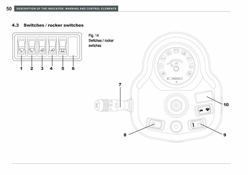
Switches / rocker switches4.3
9
10
8
7
Fig. 14 Switches / rocker switches
1 2 3 4 5 6
DesCRIpTION Of The INDICATOR, WARNING AND CONTROl elemeNTs 51WL25
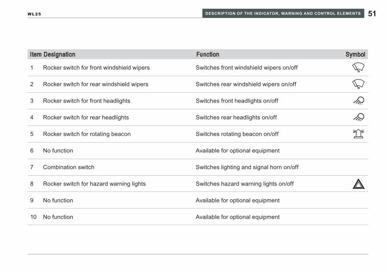
Item Designation Function Symbol
1 Rocker switch for front windshield wipers Switches front windshield wipers on/off
2 Rocker switch for rear windshield wipers Switches rear windshield wipers on/off
3 Rocker switch for front headlights Switches front headlights on/off
4 Rocker switch for rear headlights Switches rear headlights on/off
5 Rocker switch for rotating beacon Switches rotating beacon on/off
6 No function Available for optional equipment
7 Combination switch Switches lighting and signal horn on/off
8 Rocker switch for hazard warning lights Switches hazard warning lights on/off
9 No function Available for optional equipment
10 No function Available for optional equipment
DesCRIpTION Of The INDICATOR, WARNING AND CONTROl elemeNTs52
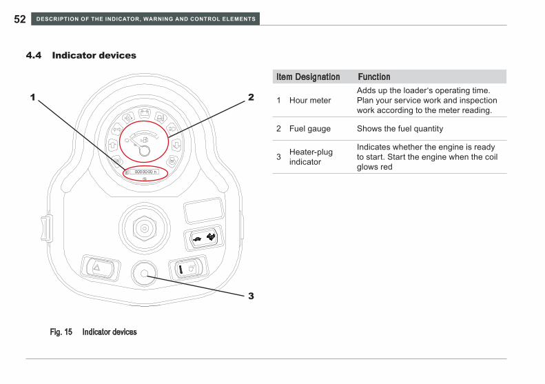
Indicator devices4.4
Indicator devicesFig. 15
1 2
3
Item Designation Function
1 Hour meterAdds up the loader‘s operating time. Plan your service work and inspection work according to the meter reading.
2 Fuel gauge Shows the fuel quantity
3 Heater-plug indicator
Indicates whether the engine is ready to start. Start the engine when the coil glows red

DesCRIpTION Of The INDICATOR, WARNING AND CONTROl elemeNTs 53WL25
OPER ATING AND OPER ATION54
OPERATING AND OPERATION5
Before starting up5.1 Fueling5.1.1
Read the operator’s manual before starting up • the loader.Only operate the loader from the operator’s • seat.Observe OSHA safety regulations.• Arrange for training with an experienced opera-• tor. Practice operating the wheel loader in a remote flat area to become familiar with control response.Using this Manual as a reference, conduct • an inspection before operating the wheel loader.After prolonged storage or inactivity, refer to the • procedure for preparing to operate the loader.
Lower the loader lift arms and attachment to the • ground and stop the engine to fuel the loader.Fire hazard – diesel fuel is flammable! Do not • smoke and avoid fire and open flames when fueling.Do not use gasoline. Use only diesel fuel. Do • not add gasoline to diesel fuel.Diesel fuel is hazardous to your health. Wear • appropriate gloves.If an inadvertent incident occurs during fuel-• ing, take immediate appropriate measures to avoid hazards. Inform the supervisor or person responsible for the fueling operation.
OPER ATING AND OPER ATION 55WL25
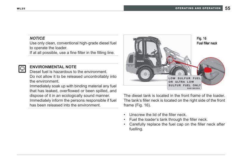
The diesel tank is located in the front frame of the loader. The tank‘s filler neck is located on the right side of the front frame (Fig. 16).
Unscrew the lid of the filler neck.• Fuel the loader‘s tank through the filler neck.• Carefully replace the fuel cap on the filler neck after • fuelling.
NOTICEUse only clean, conventional high-grade diesel fuel to operate the loader.If at all possible, use a fine filter in the filling line.
eNVIRONmeNTAl NOTeDiesel fuel is hazardous to the environment.Do not allow it to be released uncontrollably into the environment.Immediately soak up with binding material any fuel that has leaked, overflowed or been spilled, and dispose of it in an ecologically sound manner.Immediately inform the persons responsible if fuel has been released into the environment.
Fig. 16 Fuel filler neck
l O W s U l f U R f U e lO R UlTRA l O Ws U l f U R fUel O N lY
3 9 0 1 9 9 3 9 0
OPER ATING AND OPER ATION56
Before entering the cab
Check that the loader is clean and undamaged.• Check that the handles and steps are in good condition • and clean.Check that the cab windows are in good condition and • clean.Check that all safety components are present and fully • functional.Check that the rods, cylinders, hinge pins and coolers • are clean.Check that all the fasteners, joints and hinge pins fit • tightly.Check that all the safety messages and instructional • labels are present and in good condition.Check the loader for oil, fuel and coolant leaks.•
Operation5.1.2
WARNINGPersonal injury hazard.
Do not operate the loader if it is not in service- ►able condition or responding correctly to control commands. Park the machine in a safe place, lower the ►loader arms and attachment, stop the engine and notify your supervisor. Do not operate the machine until the problem ►has been corrected.Check that the safety devices are present and ►operative each time before you start up the loader.Replace damaged tires to avoid loss of produc- ►tion and stability due to sudden deflation.Maintain a neat uncluttered operator space to ►prevent slipping, tripping and potential impedi-ments to control movement.Keep the operating elements clean. ►Follow the daily servicing schedule. ►
OPER ATING AND OPER ATION 57WL25
Check:
Engine oil level• Hydraulic fluid level• Coolant level• Fuel level• Check the condition of the tires, looking for abrasion, • cuts or wear. Check the tire pressure! Ensure that the tires are inflated to the proper pressure (see tire pres-sure table).Ensure that the engine enclosures and the caps for the • fuel tank and hydraulic fluid tank are present and have been tightened.
Operator station access
WARNINGSlipping hazard.
Check that the handles and steps are in good ►condition and clean before entering and exiting the wheel loader control station..Use the attached handles and steps. ►Always get in and out with your face turned to- ►ward the loader.
OPER ATING AND OPER ATION58
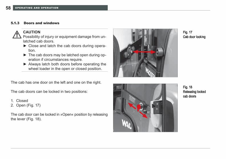
Doors and windows5.1.3
The cab has one door on the left and one on the right.
The cab doors can be locked in two positions:
Closed1. Open (Fig. 17)2.
The cab door can be locked in »Open« position by releasing the lever (Fig. 18).
Fig. 17 Cab door locking
Fig. 18 Releasing locked cab doors
CAUTIONPossibility of injury or equipment damage from un-latched cab doors.
Close and latch the cab doors during opera- ►tion. The cab doors may be latched open during op- ►eration if circumstances require. Always latch both doors before operating the ►wheel loader in the open or closed position.
OPER ATING AND OPER ATION 59WL25
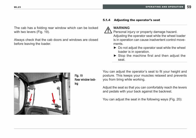
The cab has a folding rear window which can be locked with two levers (Fig. 19).
Always check that the cab doors and windows are closed before leaving the loader.
Adjusting the operator’s seat5.1.4
You can adjust the operator’s seat to fit your height and posture. This keeps your muscles relaxed and prevents you from tiring while working.
Adjust the seat so that you can comfortably reach the levers and pedals with your back against the backrest.
You can adjust the seat in the following ways (Fig. 20):
Fig. 19 Rear window lock-ing
WARNINGPersonal injury or property damage hazard.Adjusting the operator seat while the wheel loader is in operation can cause inadvertent control move-ments.
Do not adjust the operator seat while the wheel ►loader is in operation. Stop the machine first and then adjust the ►seat.
OPER ATING AND OPER ATION60
Fig. 20 Adjusting the opera-tor’s seat
2
1
3
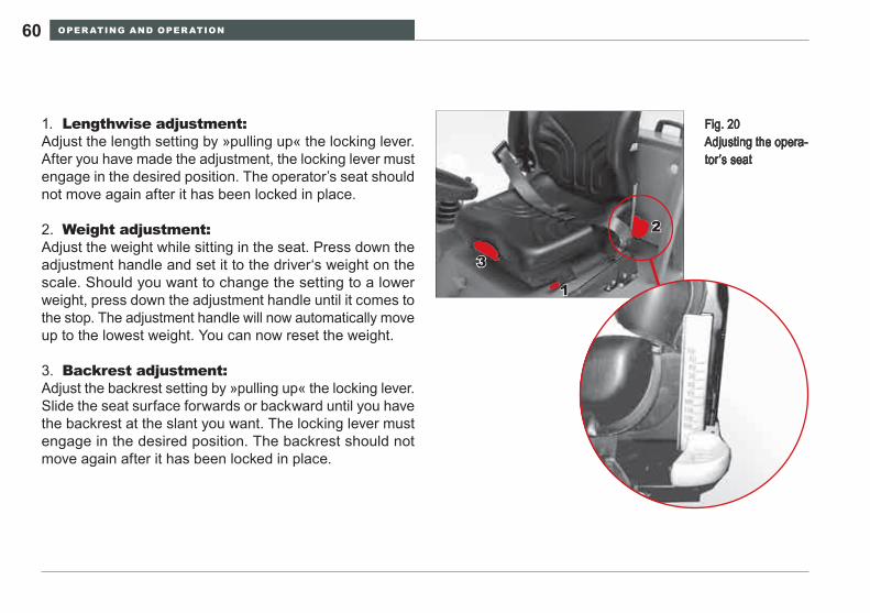
Lengthwise adjustment:1. Adjust the length setting by »pulling up« the locking lever. After you have made the adjustment, the locking lever must engage in the desired position. The operator’s seat should not move again after it has been locked in place.
Weight adjustment:2. Adjust the weight while sitting in the seat. Press down the adjustment handle and set it to the driver‘s weight on the scale. Should you want to change the setting to a lower weight, press down the adjustment handle until it comes to the stop. The adjustment handle will now automatically move up to the lowest weight. You can now reset the weight.
Backrest adjustment:3. Adjust the backrest setting by »pulling up« the locking lever. Slide the seat surface forwards or backward until you have the backrest at the slant you want. The locking lever must engage in the desired position. The backrest should not move again after it has been locked in place.

OPER ATING AND OPER ATION 61WL25
Adjusting the steering column5.1.5
You can adjust the position of the steering column lengthwise so that it fits your height and posture.
Fig. 21 Adjusting the steer-ing column
Operate the adjustment lever (Fig. 21).1. Adjust the steering column as needed.2. Let go of the adjustment lever.3.
WARNINGPersonal injury or property damage hazard.Adjusting the steering column while the wheel load-er is in operation can cause inadvertent machine movement.
Do not adjust the steering column while the ►wheel loader is in operation. Stop the machine first and then adjust the steer- ►ing column.
OPER ATING AND OPER ATION62
Seat belt5.1.6
All functions of the multi-function lever only work if the operator has fastened the seat belt and the buckle is closed.
WARNINGPersonal injury hazard.Not wearing the seat belt, or operating with a dam-aged seat belt, can result in injury to the opera-tor.
To operate the Wheel Loader, you must be ►seated in the operator’s seat and the seat belt must be properly fastened.Make sure seat belt and buckle stay clean. ►Before operation check function of seat belt ►and buckle.Replace the belt or buckle immediately if they ►are damaged.
OPER ATING AND OPER ATION 63WL25
Buckling the seat belt
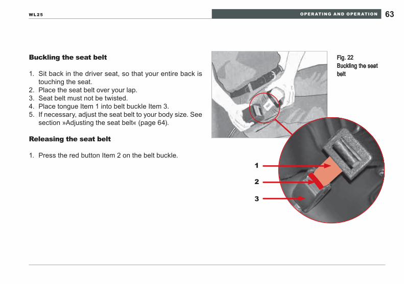
Sit back in the driver seat, so that your entire back is 1. touching the seat.Place the seat belt over your lap.2. Seat belt must not be twisted.3. Place tongue Item 1 into belt buckle Item 3.4. If necessary, adjust the seat belt to your body size. 5. See section »Adjusting the seat belt« (page 64).
Releasing the seat belt
Press the red button Item 2 on the belt buckle.1. 1
2
3
Fig. 22 Buckling the seat belt
OPER ATING AND OPER ATION64
WARNINGPersonal injury or property damage hazard.Adjusting the seat belt while the wheel loader is in operation can cause inadvertent control move-ments.
Do not adjust the seat belt while the wheel ►loader is in operation. Stop the machine first and then adjust the seat ►belt.
Adjusting the seat belt
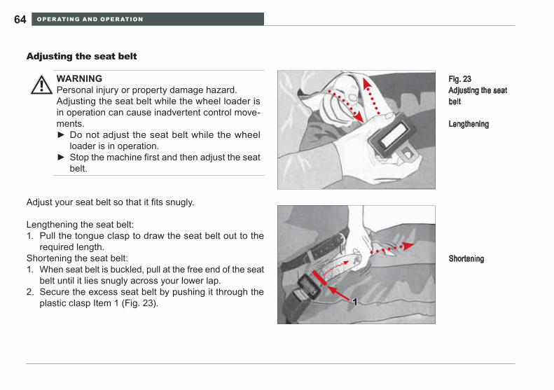
Adjust your seat belt so that it fits snugly.
Lengthening the seat belt:Pull the tongue clasp to draw the seat belt out to the 1. required length.
Shortening the seat belt:When seat belt is buckled, pull at the free end of the seat 1. belt until it lies snugly across your lower lap.Secure the excess seat belt by pushing it through the 2. plastic clasp Item 1 (Fig. 23).
Shortening
1
Fig. 23 Adjusting the seat belt
Lengthening
OPER ATING AND OPER ATION 65WL25
Starting up5.2
WARNINGPossibility of injury or equipment damage from in-operable lights or individual functions.
Do not drive the loader if the entire lighting sys- ►tem or individual functions are not working.
The warning and indicator lights display fault mes-sages from the equipment.All the rocker switches are switched on by moving them to the down position.
OPER ATING AND OPER ATION66
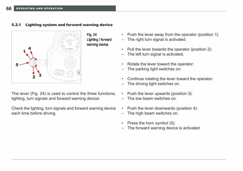
Lighting system and forward warning device5.2.1
Push the lever away from the operator (position 1):• The right turn signal is activated. –
Pull the lever towards the operator (position 2):• The left turn signal is activated. –
Rotate the lever toward the operator:• The parking light switches on. –
Continue rotating the lever toward the operator:• The driving light switches on. –
Push the lever upwards (position 3):• The low beam switches on. –
Push the lever downwards (position 4):• The high beam switches on. –
Press the horn symbol (5):• The forward warning device is activated. –
The lever (Fig. 24) is used to control the three functions, lighting, turn signals and forward warning device:
Check the lighting, turn signals and forward warning device each time before driving.
Fig. 24 Lighting / forward warning device
1
2 3
4
5
OPER ATING AND OPER ATION 67WL25
Wipers and windshield washer system5.2.2
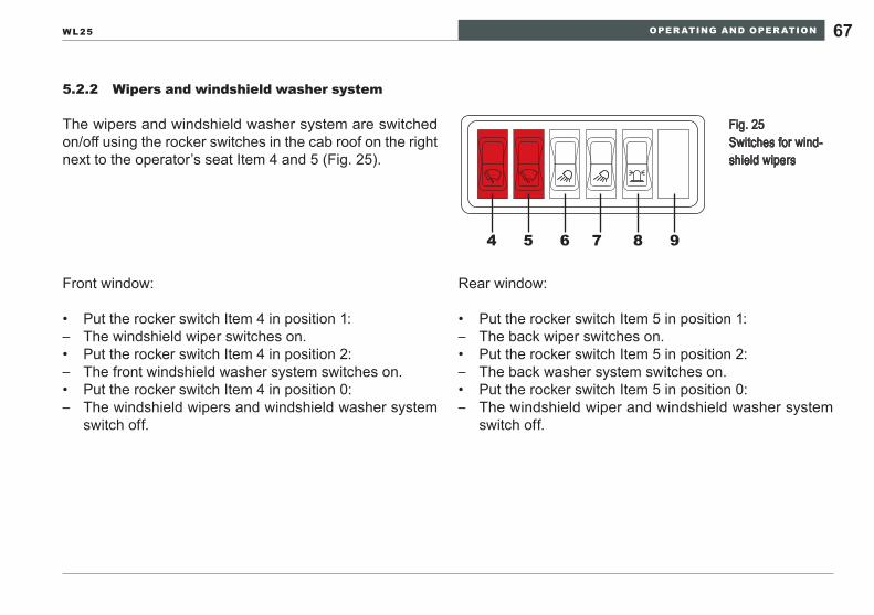
The wipers and windshield washer system are switched on/off using the rocker switches in the cab roof on the right next to the operator’s seat Item 4 and 5 (Fig. 25).
Front window:
Put the rocker switch Item 4 in position 1:• The windshield wiper switches on. –Put the rocker switch Item 4 in position 2:• The front windshield washer system switches on. –Put the rocker switch Item 4 in position 0:• The windshield wipers and windshield washer system –switch off.
Rear window:
Put the rocker switch Item 5 in position 1:• The back wiper switches on. –Put the rocker switch Item 5 in position 2:• The back washer system switches on. –Put the rocker switch Item 5 in position 0:• The windshield wiper and windshield washer system –switch off.
Fig. 25 Switches for wind-shield wipers
4 5 6 7 8 9
OPER ATING AND OPER ATION68
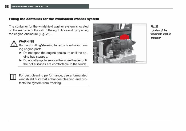
Filling the container for the windshield washer system
The container for the windshield washer system is located on the rear side of the cab to the right. Access it by opening the engine enclosure (Fig. 26).
Fig. 26 Location of the windshield washer container
WARNINGBurn and cutting/shearing hazards from hot or mov-ing engine parts.
Do not open the engine enclosure until the en- ►gine has stopped.Do not attempt to service the wheel loader until ►the hot surfaces are comfortable to the touch.
For best cleaning performance, use a formulated windshield fluid that enhances cleaning and pro-tects the system from freezing
OPER ATING AND OPER ATION 69WL25
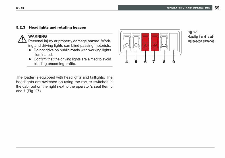
Headlights and rotating beacon5.2.3
The loader is equipped with headlights and taillights. The headlights are switched on using the rocker switches in the cab roof on the right next to the operator’s seat Item 6 and 7 (Fig. 27).
WARNINGPersonal injury or property damage hazard. Work-ing and driving lights can blind passing motorists.
Do not drive on public roads with working lights ►illuminated.Confirm that the driving lights are aimed to avoid ►blinding oncoming traffic.
Fig. 27 Headlight and rotat-ing beacon switches
4 5 6 7 8 9
OPER ATING AND OPER ATION70
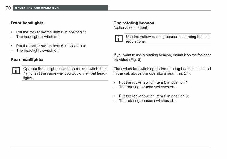
The rotating beacon
If you want to use a rotating beacon, mount it on the fastener provided (Fig. 5).
The switch for switching on the rotating beacon is located in the cab above the operator’s seat (Fig. 27).
Put the rocker switch Item 8 in position 1:• The rotating beacon switches on. –
Put the rocker switch Item 8 in position 0:• The rotating beacon switches off. –
(optional equipment)Front headlights:
Put the rocker switch Item 6 in position 1:• The headlights switch on. –
Put the rocker switch Item 6 in position 0:• The headlights switch off. –
Rear headlights:
Operate the taillights using the rocker switch Item 7 (Fig. 27) the same way you would the front head-lights.
Use the yellow rotating beacon according to local regulations.
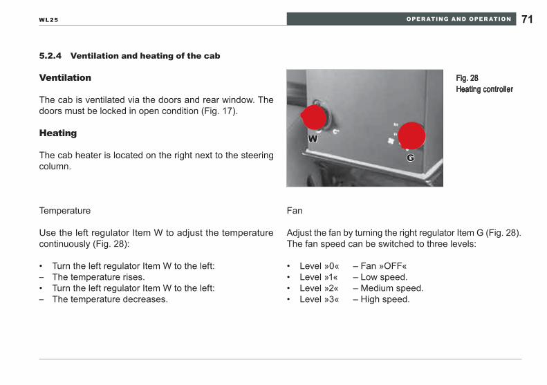
OPER ATING AND OPER ATION 71WL25
Ventilation and heating of the cab5.2.4
Ventilation
The cab is ventilated via the doors and rear window. The doors must be locked in open condition (Fig. 17).
Heating
The cab heater is located on the right next to the steering column.
Temperature
Use the left regulator Item W to adjust the temperature continuously (Fig. 28):
Turn the left regulator Item W to the left:• The temperature rises. –Turn the left regulator Item W to the left:• The temperature decreases. –
Fig. 28 Heating controller
W
G
Fan
Adjust the fan by turning the right regulator Item G (Fig. 28). The fan speed can be switched to three levels:
Level »0« – Fan »OFF«• Level »1« – Low speed.• Level »2« – Medium speed.• Level »3« – High speed.•
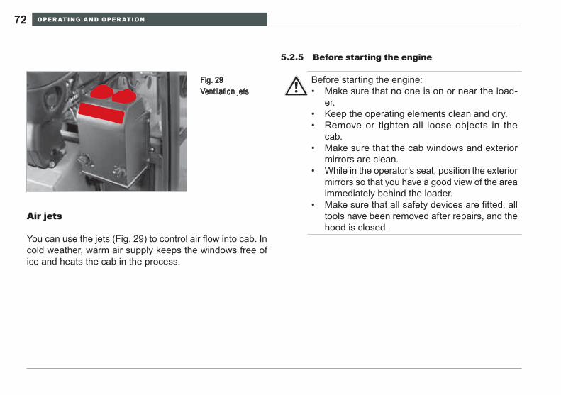
OPER ATING AND OPER ATION72
Before starting the engine5.2.5
Fig. 29 Ventilation jets
Air jets
You can use the jets (Fig. 29) to control air flow into cab. In cold weather, warm air supply keeps the windows free of ice and heats the cab in the process.
Before starting the engine:Make sure that no one is on or near the load-• er.Keep the operating elements clean and dry.• Remove or tighten all loose objects in the • cab.Make sure that the cab windows and exterior • mirrors are clean.While in the operator’s seat, position the exterior • mirrors so that you have a good view of the area immediately behind the loader.Make sure that all safety devices are fitted, all • tools have been removed after repairs, and the hood is closed.
OPER ATING AND OPER ATION 73WL25
Perform the 1. »Before entering the cab« checks prior to starting the engine (see the chapter »Operation«).Adjust the operator’s seat and the steering column as 2. needed.Adjust the rear view mirror / exterior mirror.3. Put on your 4. seat belt.
Starting the engine5.2.6
Check that no one is in the loader‘s danger • area.Do not use ether as a starting aid.• Do not use the loader if the »starter inhibitor« • does not function.Only start the loader from the operator’s seat.•
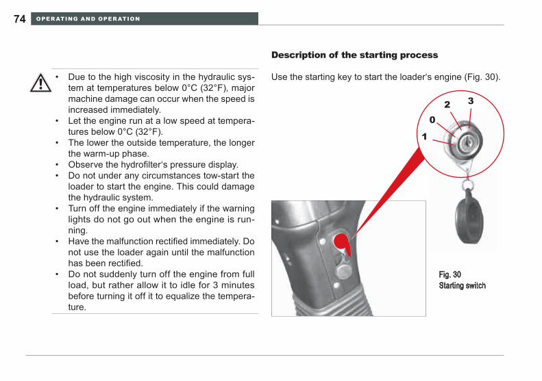
OPER ATING AND OPER ATION74
Description of the starting process
Use the starting key to start the loader‘s engine (Fig. 30).
Fig. 30 Starting switch
1
2 3
0
Due to the high viscosity in the hydraulic sys-• tem at temperatures below 0°C (32°F), major machine damage can occur when the speed is increased immediately.Let the engine run at a low speed at tempera-• tures below 0°C (32°F).The lower the outside temperature, the longer • the warm-up phase.Observe the hydrofilter‘s pressure display.• Do not under any circumstances tow-start the • loader to start the engine. This could damage the hydraulic system.Turn off the engine immediately if the warning • lights do not go out when the engine is run-ning.Have the malfunction rectified immediately. Do • not use the loader again until the malfunction has been rectified.Do not suddenly turn off the engine from full • load, but rather allow it to idle for 3 minutes before turning it off it to equalize the tempera-ture.
OPER ATING AND OPER ATION 75WL25
Push the foot accelerator.1. Starting:2. Put in the key - level 0 = no operating voltage.• Turn the key left against the spring pressure until the • heater-plug indicator is illuminated
Level 2 = Preheating At low temperatures, preheat the engine at level 3 a
maximum of 1 minute long.Turn the key to the right - level 2 = operating voltage;•
The indicator lights (oil pressure, dynamo) must be il-luminatedContinue to turn the key right against the spring pres-• sure - level 3 = startingLet go of the key as soon as the engine starts - the • key will return to level 2 - and the indicator lights will go out.Check if all the indicator lights have gone out, correct any 3. possible defects before driving off with the loader.
If the engine does not start
Attempt to start the loader for a maximum of 20 sec-• onds.Wait one minute.• Repeat the starting process.• If the engine will not start after two attempts, look for • the cause in the malfunction table (»Troubleshooting and emergency maintenance«) or contact a specialist garage.
It is absolutely not possible to start the engine by tow-starting the loader. This could damage the hy-draulic system.
OPER ATING AND OPER ATION76
Propulsion operation5.3
Description of the propulsion hydraulics
See »Hydraulics« section of 3.1 Technical Description on page 40.
Preparation for travel in public traffic5.3.1
Secure the attachment:1. Ensure that the bucket has been emptied and has been –lowered to transport position.Put the tooth guard on the bucket. –Check the lighting system, and if applicable, the function 2. of the rotating beacon.
Switch on the headlights.Adjust the attachment height for clearance with the road 3. surface, but not more than necessary for safe transport to avoid visibility restrictions and reduced stability.
Do not travel with the loader arms completely raised to avoid collision with overhead objects such as viaducts and electrical power lines.
After adjusting the loader arm height, engage the travel lock to prevent unintentional control activation.Confirm that the seat belt is properly adjusted.4. Survey the surrounding area to ensure that moving into 5. traffic can be done safely.
Before you start travel, make sure that the ma-• chine complies with the relevant local regula-tions and has a valid operating license.Fork prongs of pallet forks must be dismantled • before undertaking trips in public traffic.
OPER ATING AND OPER ATION 77WL25
Travel speed5.3.2
WARNINGPersonal injury hazard from tipping or roll-over incidents. To avoid tipping and roll-over incidents:
Keep the loader lift arms and bucket load as ►low as practicalKeep the loading site level. ►match the speed to working conditions to main- ►tain control of the machineConstantly survey the work area for obstruc- ►tions, vehicles and people to avoid collisions and runover incidents.
All functions of the multi-function lever only works if the operator has attached the seat belt firmly and comfortably around the lower torso.Indicator lights will indicate the travel directions and gears selected.When the parking brake is engaged the loader‘s drive is switched off (driving lock). This is shown by the illuminated parking brake indicator. It is not possible to travel until the parking brake has been released and the indicator light has gone out.
OPER ATING AND OPER ATION78
Changing travel directions
Use the slide switch Item 1 (Fig. 31) to change the loader‘s travel direction. After the engine has been started, the gear changer is in neutral position.
Travel direction switch in middle position:• Gear changer in Neutral –Push the travel direction switch forward:• The indicator light – »2« (Fig. 13, page 48) is illuminat-ed.
The loader travels forward.Push the travel direction switch back:• The indicator light – »8« (Fig. 13, page 48) is illuminat-ed.
The loader travels in reverse.
WARNINGPersonal injury and machine damage hazards from abrupt directional changes. Actuating the direction switch when the loader is moving will cause the moving loader to change direction abruptly.
Do not change the travel direction switch posi- ►tion when the loader is moving in either forward or reverse.Before and after changing direction with the ►loader stopped, confirm that the indicator lights are in agreement with the intended direction selected.If the direction control does not respond or the ►indicator light does not illuminate, move the ma-chine to a safe location, lower the loader arms until the attachment is resting on the ground, stop the engine and inform the supervisor of a service need.Do not operate the loader until a technician ►has restored the function before operating the machine.
Be careful when traveling in snowy and icy condi-tions. Reduce your travel speed considerably in the event of bad weather.If the loader is equipped with the optional equip-ment »Warning buzzer for reverse drive«, a warning buzzer sounds when reverse gear is engaged. The sound is to warn persons who are in the vicinity of the loader that the loader is going into reverse.
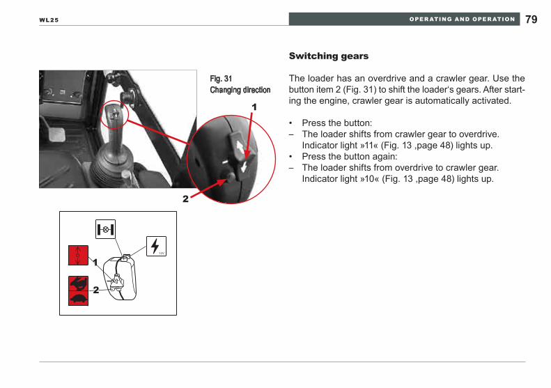
OPER ATING AND OPER ATION 79WL25
Switching gears
The loader has an overdrive and a crawler gear. Use the button item 2 (Fig. 31) to shift the loader‘s gears. After start-ing the engine, crawler gear is automatically activated.
Press the button:• The loader shifts from crawler gear to overdrive. –
Indicator light »11« (Fig. 13 ,page 48) lights up.Press the button again:• The loader shifts from overdrive to crawler gear. –
Indicator light »10« (Fig. 13 ,page 48) lights up.
12V
2
1
Fig. 31 Changing direction
1
2
OPER ATING AND OPER ATION80
Braking and stopping
To change the driving speed independently of the engine speed, you can push the braking-inching pedal on the next to the steering column. The first part of the pedal‘s path adjusts the drive back down, then the brake system is actuated. Pushing the braking-inching pedal allows you to continu-ously reduce the pump flow rate until the loader has come to a halt without wearing out the material. This allows you to also drive very slowly at a high engine speed.
Reduce the loader‘s driving speed by decreasing the • engine speed.To brake the loader, step on the braking-inching ped-• al.To stop, step on the braking-inching pedal until the loader • has come to a stop.Shift to neutral.• Pull the lever for the parking brake.•
Loader travel
Release the parking brake after the engine has warmed • up.The handbrake indicator light will go off. The loader is –ready to be driven.Select the drive direction by actuating the drive direc-• tion switch.The indicator light shows the drive direction selected. –You can travel.Push the accelerator.• The loader will be brought up to speed smoothly. –
The loader‘s driving speed is proportional to the accelera-tor‘s displacement.
low engine speed = low driving speed• high engine speed = high driving speed• p
OPER ATING AND OPER ATION 81WL25
Changing the travel direction Stopping and parking5.3.3
Reduce the travel speed until the loader has come to 1. a halt.Move the travel direction switch in the other direction.2. Push the accelerator so that the loader starts moving.3.
Stop the machine in a safe location out of the • traffic flow pattern and on firm ground.Lower the loader arms with bucket or attach-• ment until resting on the ground.Remove the starting key before leaving the op-• erator seat.
WARNINGPersonal injury and machine damage hazards from abrupt directional changes. Actuating the direction switch when the loader is moving will cause the moving loader to change direction abruptly.
Do not change the travel direction switch posi- ►tion when the loader is moving in either forward or reverse.
It is not necessary to depress the inching pedal to the end of the movement every time you change direction.
Bring the loader smoothly to a halt by easing up on the accelerator or actuating the braking-inching pedal and secure it as described in section 9 page 125 »Securing the loader«.
OPER ATING AND OPER ATION82
Work operation5.4
Before starting to work with the loader:Survey the work area to determine if people, • vehicles and obstacles are in the immediate work area. Do not start work until the work area is clear.Constantly survey the area during working op-• eration to avoid collision with people, vehicles and obstacles that may inadvertently enter the loader work area. Verify that all controls are working correctly and • the indicator lights are functioning. Move the lift arm and attachment hydraulics to assure smooth control response.Jerky, spongy or delayed control response may • indicate that air has entered the hydraulic sys-tem. Cycle the hydraulic system a few times. If the controls become smooth, the air has been eliminated from the system. If the problem per-sists, do not operate the machine in this condi-tion. Advise the supervisor and have a techni-cian determine the source of air entrainment. Inspect attachments to confirm they are in ser-• viceable condition and are properly connected to the loader arms.
In the event of power loss (failure of the engine and/or driving or working hydraulics), lower the lift frame to the ground immediately and relieve the control circuits and hydraulic lines of pressure. Read sec-tion 7 page 121 »Lowering loader arms«.
OPER ATING AND OPER ATION 83WL25
Each time before starting work
Examine the loader for visible defects prior to each work • shift.Check the functioning of the operating equipment.• Check the functioning of the brakes and warning de-• vices.Report any defects to the supervisor and, when chang-• ing shifts, to the driver taking your place.Perform the checks described in sections • 5.1 (page 56) and 5.2.5 (page 72).
OPER ATING AND OPER ATION84
Operating lever for Loader lift arms5.4.1
Use the multi-function lever to control the movements of the lift frame Item A (Fig. 32). The multi-function lever is located on the right next to the operator’s seat.
Keep the loader lift arms and attachment as low • as practical when traveling. This improves vis-ibility and stability, and reduces the risk of strik-ing overhead objects such as power lines. Do not activate float control of the loader arms • until the bucket or attachment is in contact with the ground or surface to be back dragged. En-gaging float with the lift arms raised will cause rapid descent of the lift arms.Do not engage the loader controls unless • seated in the operator seat with the seat belt fastened.Operate the loader with smooth steady control • motion. Rapid and jerky control motion is inef-ficient and will cause operator fatigue and cause potential harm to the loader.Do not leave the operator seat until the loader • lift arms and attachment have been lowered to the ground.
All functions of the multi-function lever only works if the operator has attached the seat belt and the buckle is closed.The lift frame float position is located on the »Low-er« and »Tilting out« function. When the multi-function lever is released, it automatically returns to the 0 position (except when in float position).
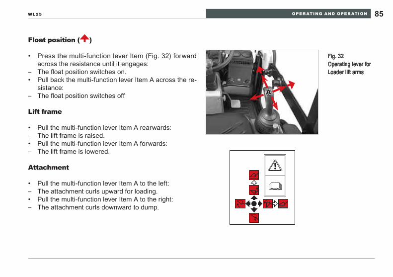
OPER ATING AND OPER ATION 85WL25
Float position ( )
Press the multi-function lever Item (Fig. 32) forward • across the resistance until it engages:The float position switches on. –Pull back the multi-function lever Item A across the re-• sistance:The float position switches off –
Lift frame
Pull the multi-function lever Item A rearwards:• The lift frame is raised. –Pull the multi-function lever Item A forwards:• The lift frame is lowered. –
Attachment
Pull the multi-function lever Item A to the left:• The attachment curls upward for loading. –Pull the multi-function lever Item A to the right:• The attachment curls downward to dump. –
Fig. 32 Operating lever for Loader lift arms
A
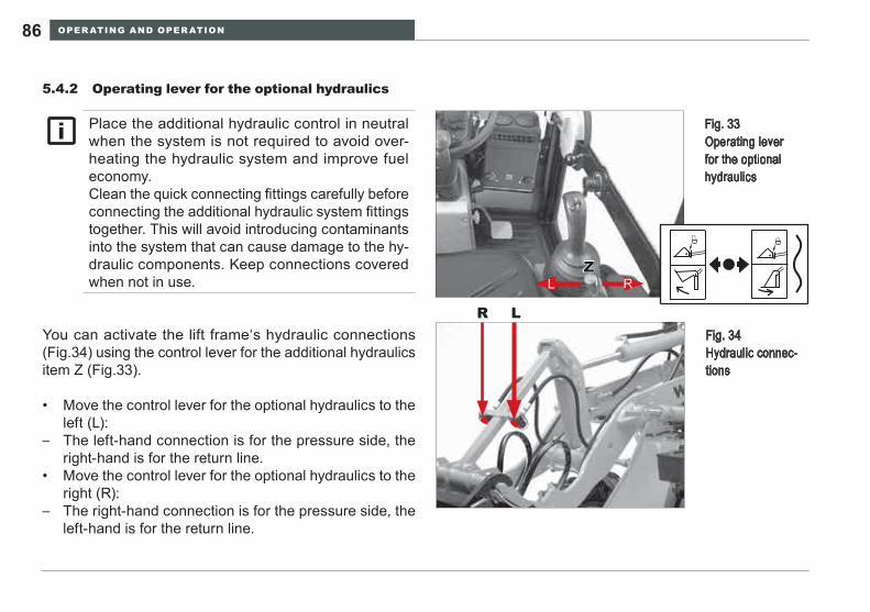
OPER ATING AND OPER ATION86
You can activate the lift frame‘s hydraulic connections (Fig.34) using the control lever for the additional hydraulics item Z (Fig.33).
Move the control lever for the optional hydraulics to the • left (L):The left-hand connection is for the pressure side, the –right-hand is for the return line.Move the control lever for the optional hydraulics to the • right (R):The right-hand connection is for the pressure side, the –left-hand is for the return line.
Operating lever for the optional hydraulics5.4.2
Place the additional hydraulic control in neutral when the system is not required to avoid over-heating the hydraulic system and improve fuel economy.Clean the quick connecting fittings carefully before connecting the additional hydraulic system fittings together. This will avoid introducing contaminants into the system that can cause damage to the hy-draulic components. Keep connections covered when not in use.
Fig. 33 Operating lever for the optional hydraulics
ZRL
R L Fig. 34
Hydraulic connec-tions
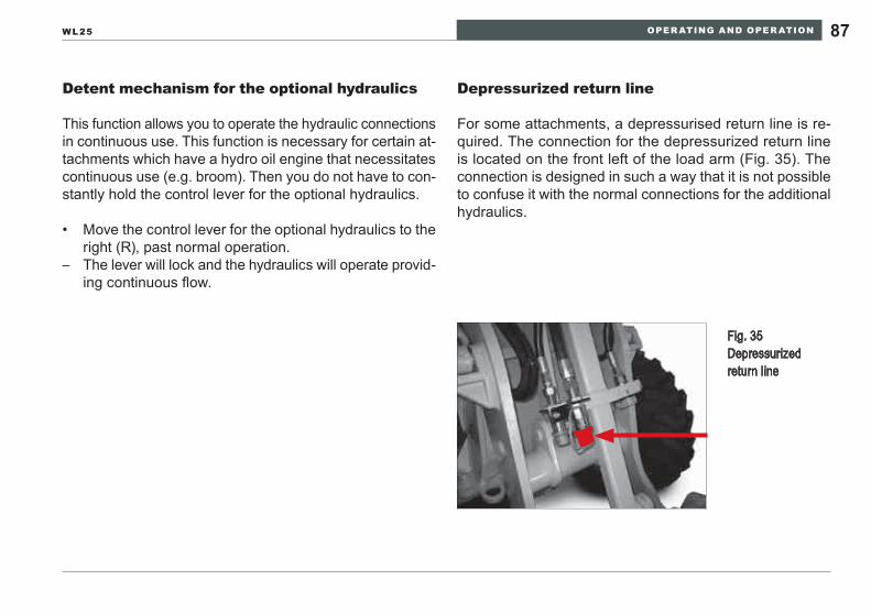
OPER ATING AND OPER ATION 87WL25
Depressurized return line
For some attachments, a depressurised return line is re-quired. The connection for the depressurized return line is located on the front left of the load arm (Fig. 35). The connection is designed in such a way that it is not possible to confuse it with the normal connections for the additional hydraulics.
Detent mechanism for the optional hydraulics
This function allows you to operate the hydraulic connections in continuous use. This function is necessary for certain at-tachments which have a hydro oil engine that necessitates continuous use (e.g. broom). Then you do not have to con-stantly hold the control lever for the optional hydraulics.
Move the control lever for the optional hydraulics to the • right (R), past normal operation.The lever will lock and the hydraulics will operate provid- –ing continuous flow.
Fig. 35 Depressurized return line
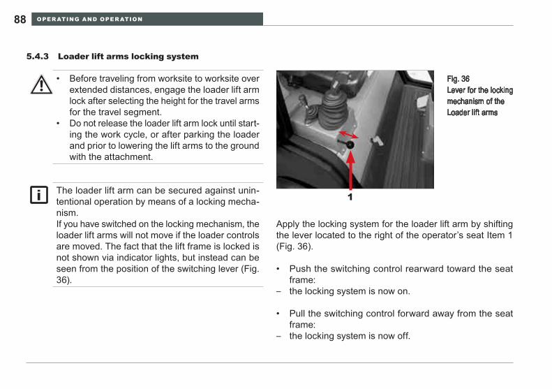
OPER ATING AND OPER ATION88
Apply the locking system for the loader lift arm by shifting the lever located to the right of the operator’s seat Item 1 (Fig. 36).
Push the switching control rearward toward the seat • frame:the locking system is now on. –
Pull the switching control forward away from the seat • frame:the locking system is now off. –
Loader lift arms locking system5.4.3
Fig. 36 Lever for the locking mechanism of the Loader lift arms
1
Before traveling from worksite to worksite over • extended distances, engage the loader lift arm lock after selecting the height for the travel arms for the travel segment. Do not release the loader lift arm lock until start-• ing the work cycle, or after parking the loader and prior to lowering the lift arms to the ground with the attachment.
The loader lift arm can be secured against unin-tentional operation by means of a locking mecha-nism.If you have switched on the locking mechanism, the loader lift arms will not move if the loader controls are moved. The fact that the lift frame is locked is not shown via indicator lights, but instead can be seen from the position of the switching lever (Fig. 36).
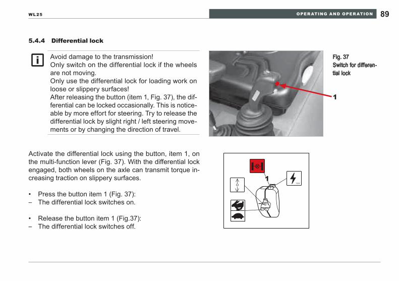
OPER ATING AND OPER ATION 89WL25
Differential lock5.4.4
Activate the differential lock using the button, item 1, on the multi-function lever (Fig. 37). With the differential lock engaged, both wheels on the axle can transmit torque in-creasing traction on slippery surfaces.
Press the button item 1 (Fig. 37):• The differential lock switches on. –
Release the button item 1 (Fig.37):• The differential lock switches off. –
12V
1
Avoid damage to the transmission!Only switch on the differential lock if the wheels are not moving.Only use the differential lock for loading work on loose or slippery surfaces!After releasing the button (item 1, Fig. 37), the dif-ferential can be locked occasionally. This is notice-able by more effort for steering. Try to release the differential lock by slight right / left steering move-ments or by changing the direction of travel.
Fig. 37 Switch for differen-tial lock
1
OPER ATING AND OPER ATION90
Changing attachments5.4.5
This operator’s manual describes only the use of the fol-lowing attachments:
Light cargo buckets• Earth buckets• Earth buckets with digging teeth•
If you wish to use additional attachments with your loader, please observe the following:
Contact your Wacker Neuson dealer before using any at-tachment not in the approved list. The dealer and Wacker Neuson technical staff can determine the compatibility of the proposed attachment.
Use only Wacker Neuson -approved attach-• ments for your loader. Wacker Neuson is not liable in the event of other attachments being used.Do not exceed the rated load capacity of the • wheel loader as stated in the specifications. Exceeding the rated capacity can create unin-tended hazards and reduce the operating life of the loader.Replace the hoses on the loader with original • equipment hose assemblies supplied by your Wacker Neuson dealer. These assemblies meet the exacting standards of performance of the new machine.Make sure to match the SAE designations when • ordering replacement hoses and/or fittings. Con-tact your Wacker Neuson dealer for assistance in obtaining replacement parts.Observe the safety instructions for changing • attachments.
Wacker Neuson is not liable for changes made without its approval.
OPER ATING AND OPER ATION 91WL25
Before assembly, start-up or maintenance, read the 1. operator’s manual for the relevant attachment.Practice using the attachment before working with it the 2. first time. Familiarize yourself ahead of time with all the functions and control elements.
When loading, adjust your driving speed to the • material being loaded and traction conditions.Avoid contact with hydraulic fluid in the event of • pressurized leakage. In the event high pressure fluid comes in contact with skin, or if hydraulic fluid enters the eye, seek immediate treatment in an emergency room.Do not use an attachment unless it is in service-• able condition.Before attempting to uncouple an attachment, • read the instructions for the uncoupling process. Confirm that the attachment will not move when removed from the loader lift arms.To avoid personal hazards and potential ma-• chine damage, confirm that the attachment is properly and firmly connected to the loader lift arms before use.Do not perform service or repairs on the attach-• ment unless the loader and loader lift arms are secured as described in section 9 page 125 »Securing the Loader«.
NOTICEUnapproved attachments could overload the loader. This can result in damage to the loader.
OPER ATING AND OPER ATION92
Coupling of attachments
Drive the loader up to the attachment (Fig. 38). 1. Bring the receptacle frame Item 1 under the mounting 2. brackets Item 2.Raise the lift frame and curl the attachment bracket to 3. mate the coupler surface together.Move the levers of the locking bolts Item 3 downward, 4. so that the bolts engage in the tabs of the attachment Item 4.Check that the locking bolts fit correctly in the tabs Item 5. 4.
eNVIRONmeNTAl NOTeHydraulic oil is hazardous to the environment. Do not allow it to be released uncontrollably into the environment.
WARNINGPersonal injury hazard.
Check the locking bolts item 4 (figure 39) to ►avoid unintentional disconnection of the attach-ment. Confirm that the hydraulic couplings are correctly matched to operate the attachment.Pressurized hydraulic oil can penetrate the skin, ►causing infections. If this occurs, seek immediate emergency room ►treatment.Oil entering the eyes must also be treated im- ►mediately in an emergency room.
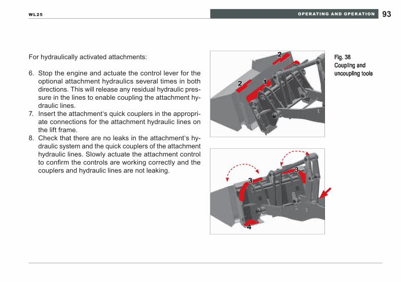
OPER ATING AND OPER ATION 93WL25
Fig. 38 Coupling and uncoupling tools
2
2 1
33
4
For hydraulically activated attachments:
Stop the engine and actuate the control lever for the 6. optional attachment hydraulics several times in both directions. This will release any residual hydraulic pres-sure in the lines to enable coupling the attachment hy-draulic lines.Insert the attachment‘s quick couplers in the appropri-7. ate connections for the attachment hydraulic lines on the lift frame.Check that there are no leaks in the attachment‘s hy-8. draulic system and the quick couplers of the attachment hydraulic lines. Slowly actuate the attachment control to confirm the controls are working correctly and the couplers and hydraulic lines are not leaking.
OPER ATING AND OPER ATION94
Lower the attachment.1. Stop the engine and actuate the control lever for the 2. attachment hydraulics several times in both directions to release residual hydraulic pressure.Disconnect the hydraulic couplers and place covers over 3. the exposed ends to exclude foreign material.Place the hydraulic hoses over the attachment.4. Move the levers of the locking bolts Item 3 (Fig. 38) 5. upward, so that the bolts are pulled out of the tabs of the attachment Item 4.Slightly lower the loader lift arms to disengage the upper 6. attachment support coupler halves. Activate the bucket curl, rotating the lower portion of the loader frame cou-pler away from the attachment coupler.
(This releases the receptacle frame item 1 (Fig. 38) from the mounting brackets Item 2 (Fig. 38)).Back the loader away from the attachment if the recep-7. tacle frame is free.
Uncoupling attachments
Lower the attachment until it is firmly resting on • a hard surface.Close attachments with movable components • such as clamshells.Actuate the attachment controls through the full • range of motion to release residual hydraulic pressure.If the attachment is equipped with integral sup-• ports, extend them to the support position.Place the attachment only on a hard, even foun-• dation.
eNVIRONmeNTAl NOTeWhen uncoupling the hydraulic connections, hold a pan under the additional hydraulics‘ quick couplers to catch any oil that might run out. Dispose of it in an ecologically sound way.
OPER ATING AND OPER ATION 95WL25
Bucket5.4.6 Function
The light cargo bucket / earth bucket attachments are in-tended for loosening, picking up, transporting and dumping materials.
Attaching the bucket
Read the chapter »Changing attachments« (Section 5.4.5, page 90).
Operating element
Operate the bucket using the control lever for the lift frame. Read the chapter »Operating lever for Loader lift arms« (Section 5.4.1, page 84).
NOTICEAvoid overloading. Observe the maximum permis-sible payload.Operate the control lever carefully.
The light cargo bucket is used for light materials such as grain, maize and pellets.The earth bucket is used for heavy materials such as gravel, sand, soil and stone.
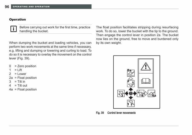
OPER ATING AND OPER ATION96
Operation
When dumping the bucket and loading vehicles, you can perform two work movements at the same time if necessary, e.g. lifting and dumping or lowering and curling to load. To do so it is necessary to overlay the movement on the control lever (Fig. 39).
0 = Zero position1 = Lift2 = Lower2a = Float position3 = Tilt in4 = Tilt out4a = Float position
The float position facilitates stripping during resurfacing work. To do so, lower the bucket with the tip to the ground. Then engage the control lever in position 2a. The bucket now lies on the ground, free to move and burdened only by its own weight.
Control lever movementsFig. 39
0
1
2
2a
43 4a
Before carrying out work for the first time, practice handling the bucket.
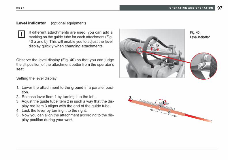
OPER ATING AND OPER ATION 97WL25
Level indicator
Observe the level display (Fig. 40) so that you can judge the tilt position of the attachment better from the operator’s seat.
Setting the level display:
Lower the attachment to the ground in a parallel posi-1. tion.Release lever item 1 by turning it to the left.2. Adjust the guide tube item 2 in such a way that the dis-3. play rod item 3 aligns with the end of the guide tube.Lock the lever by turning it to the right.4. Now you can align the attachment according to the dis-5. play position during your work.
Fig. 40 Level indicator
a b
1
2
3
If different attachments are used, you can add a marking on the guide tube for each attachment (Fig. 40 a and b). This will enable you to adjust the level display quickly when changing attachments.
(optional equipment)
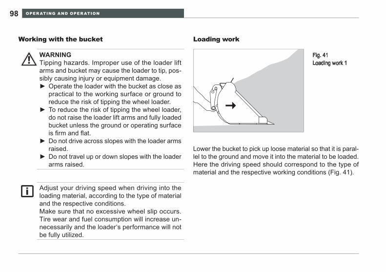
OPER ATING AND OPER ATION98
Loading work
Lower the bucket to pick up loose material so that it is paral-lel to the ground and move it into the material to be loaded. Here the driving speed should correspond to the type of material and the respective working conditions (Fig. 41).
Working with the bucket
Fig. 41 Loading work 1
WARNINGTipping hazards. Improper use of the loader lift arms and bucket may cause the loader to tip, pos-sibly causing injury or equipment damage.
Operate the loader with the bucket as close as ►practical to the working surface or ground to reduce the risk of tipping the wheel loader. To reduce the risk of tipping the wheel loader, ►do not raise the loader lift arms and fully loaded bucket unless the ground or operating surface is firm and flat. Do not drive across slopes with the loader arms ►raised. Do not travel up or down slopes with the loader ►arms raised.
Adjust your driving speed when driving into the loading material, according to the type of material and the respective conditions.Make sure that no excessive wheel slip occurs. Tire wear and fuel consumption will increase un-necessarily and the loader‘s performance will not be fully utilized.
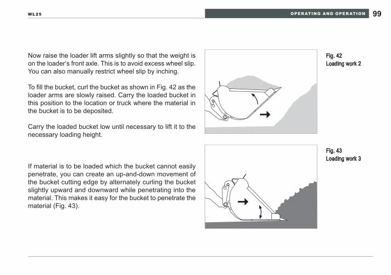
OPER ATING AND OPER ATION 99WL25
Now raise the loader lift arms slightly so that the weight is on the loader‘s front axle. This is to avoid excess wheel slip. You can also manually restrict wheel slip by inching.
To fill the bucket, curl the bucket as shown in Fig. 42 as the loader arms are slowly raised. Carry the loaded bucket in this position to the location or truck where the material in the bucket is to be deposited.
Carry the loaded bucket low until necessary to lift it to the necessary loading height.
If material is to be loaded which the bucket cannot easily penetrate, you can create an up-and-down movement of the bucket cutting edge by alternately curling the bucket slightly upward and downward while penetrating into the material. This makes it easy for the bucket to penetrate the material (Fig. 43).
Fig. 42 Loading work 2
Fig. 43 Loading work 3
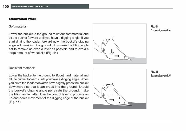
OPER ATING AND OPER ATION100
Excavation work
Soft material:
Lower the bucket to the ground to lift out soft material and tilt the bucket forward until you have a digging angle. If you start driving the loader forward now, the bucket‘s digging edge will break into the ground. Now make the tilting angle flat to remove as even a layer as possible and to avoid a large amount of wheel slip (Fig. 44).
Resistant material:
Lower the bucket to the ground to lift out hard material and tilt the bucket forwards until you have a digging angle. When you drive the loader forwards now, slightly press the bucket downwards so that it can break into the ground. Should the bucket‘s digging angle penetrate the ground, make the tilting angle flatter. Use the control lever to produce an up-and-down movement of the digging edge of the bucket (Fig. 45).
Fig. 44 Excavation work 4
Fig. 45 Excavation work 5
OPER ATING AND OPER ATION 101WL25
Tip-overs5.4.7
If the machine tips over, or in the event of an ex-treme slope condition, take the following steps to avoid engine damage:
Stop the engine as quickly as practical to avoid • damage from lubrication starvation.Do not operate the engine or machine after an • incident until a technician has inspected and corrected any damage resulting from the in-cident.
eNVIRONmeNTAl NOTeRight the loader as soon as possible so that oil and fuel cannot escape.Immediately soak up with binding material any oil or fuel that has leaked, and dispose of it sepa-rately from other waste in an ecologically sound manner.
OPER ATING AND OPER ATION102
At low outside temperatures
Precaution measures for various weather conditions5.4.8
At high outside temperatures
Take the following precautions at high temperatures to pre-vent the loader from being damaged:
Regularly check the cooling system:• Keep the engine coolant and oil coolers clean -Make sure that the coolant level is always correct -Use the proper coolant mix. -Regularly check the cooling system for leaks -Regularly check the condition and tension of the fan -pulley
Use engine lubricating oil of the proper viscosity • class.Regularly check the engine air filter.•
Do not use starting aids such as ether. The • manifold heating system can ignite the ether, causing an explosion. Snow, mud and freezing rain reduce traction. • Reduce speed and avoid slopes under these conditions. Maintain the windshield cleaning fluid system • and keep all windows clean. Visibility is a basic necessity for safe operation.
Additional starting aids may be required if the tem-perature is –18°C (0°F) or less. Typically, these aids are auxiliary engine oil and coolant heaters along with additional battery cranking capacity.
OPER ATING AND OPER ATION 103WL25
Take the following precautions at low temperatures to pre-vent the loader from being damaged and to make the loader easier to start:
Use the proper coolant mix.• Use engine lubricating oil of the proper viscosity • class.Use diesel fuel for low temperatures.• Fill the fuel tank at the end of the work shift.• Make sure the battery is always fully charged.• Install the cold starting aid (see note above!).•
Hydraulic and lubricating fluids are more viscous when cold. When ambient temperatures are at or near the freezing point of 0°C (32°F), permit the engine, drivetrain and hydraulic system to warm up at idle speed until the temperature indicator for the system indicates warming has progressed.
Operate the wheel loader slowly and smoothly • to accelerate the warming process.Observe the hydraulic system filter pressure • display to determine if pressure is excessive.Do not connect two 12V batteries in series (+ • to –) and then connect the remaining battery poles to the starter or starter solenoid. This will damage the electrical system
OPER ATING AND OPER ATION104
Additional equipment5.5
Activate the loader lift arm damper control to im-prove ride quality and stability during travel with the loader. Disengage the damper control before at-tempting to use the loader for loading operations.
Before engaging the damper feature, verify that the loader bucket or attachment has sufficient clear-ance with the ground to avoid contact while travel-ing. The loader lift arms will drop when the damper function is activated. To negate pitching motion of the loader chassis when traveling, raise the bucket or attachment approximately 30 cm (12”) to compensate for the vertical movement of the bucket or attachment as the feature moves.
Loader lift arm damping The loader lift arm damping is engaged by means of the pull switch adjacent to the operator’s seat on the right hand side (Fig. 46). There is a red indicator light in the switch.
Engaging the feature reduces the effect of uneven ground on the attitude of the machine when traveling at higher speeds. It reduces pitching by use of the loader arm mass and hydraulic system to act as a damper. This reduces the stress on the wheel loader and the motion imparted to the operator through the seat. This feature reduces the effect, but does not replace the operator’s responsibility for ob-serving the terrain and making speed reductions to avoid extreme motion over undulating surfaces.
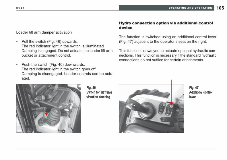
OPER ATING AND OPER ATION 105WL25
Fig. 46 Switch for lift frame vibration damping
Loader lift arm damper activation
Pull the switch (Fig. 46) upwards:• The red indicator light in the switch is illuminated
Damping is engaged. Do not actuate the loader lift arm, –bucket or attachment control.
Push the switch (Fig. 46) downwards:• The red indicator light in the switch goes off
Damping is disengaged. Loader controls can be actu- –ated.
Fig. 47 Additional control lever
Hydro connection option via additional control device
The function is switched using an additional control lever (Fig. 47) adjacent to the operator’s seat on the right.
This function allows you to actuate optional hydraulic con-nections. This function is necessary if the standard hydraulic connections do not suffice for certain attachments.
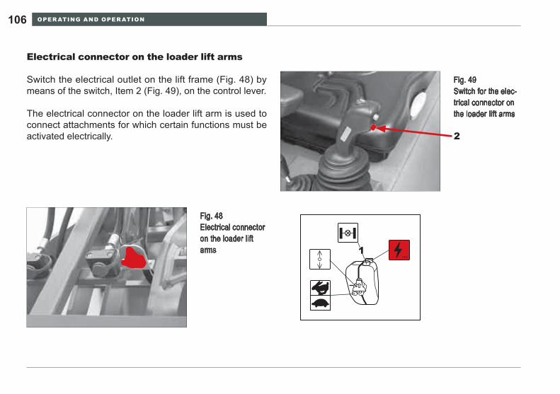
OPER ATING AND OPER ATION106
12V
1
Electrical connector on the loader lift arms
Switch the electrical outlet on the lift frame (Fig. 48) by means of the switch, Item 2 (Fig. 49), on the control lever.
The electrical connector on the loader lift arm is used to connect attachments for which certain functions must be activated electrically.
Fig. 48 Electrical connector on the loader lift arms
Fig. 49 Switch for the elec-trical connector on the loader lift arms
2
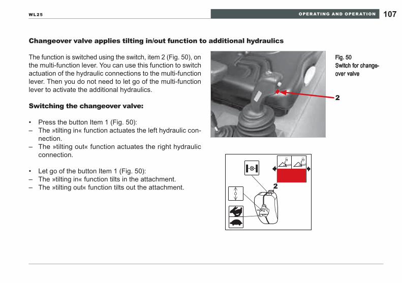
OPER ATING AND OPER ATION 107WL25
Changeover valve applies tilting in/out function to additional hydraulics
The function is switched using the switch, item 2 (Fig. 50), on the multi-function lever. You can use this function to switch actuation of the hydraulic connections to the multi-function lever. Then you do not need to let go of the multi-function lever to activate the additional hydraulics.
Switching the changeover valve:
• Press the button Item 1 (Fig. 50):– The »tilting in« function actuates the left hydraulic con-
nection.– The »tilting out« function actuates the right hydraulic
connection.
• Let go of the button Item 1 (Fig. 50):– The »tilting in« function tilts in the attachment.– The »tilting out« function tilts out the attachment.
Fig. 50 Switch for change-over valve
2
2
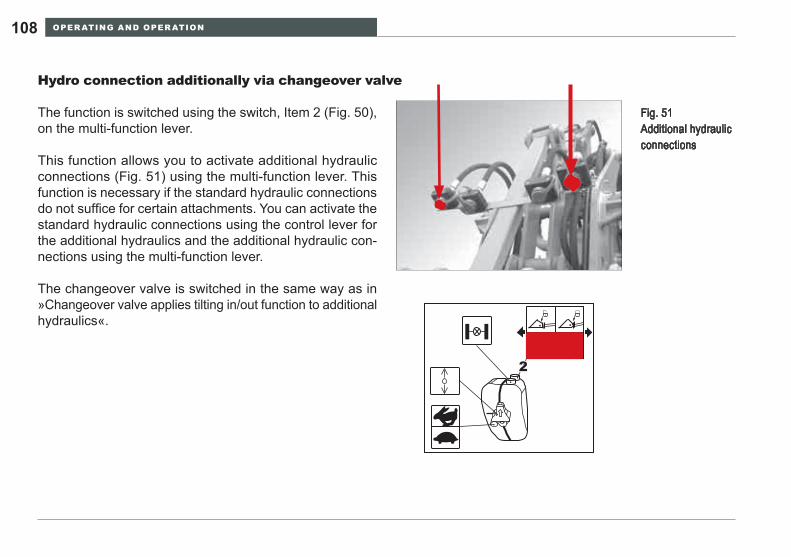
OPER ATING AND OPER ATION108
Hydro connection additionally via changeover valve
The function is switched using the switch, Item 2 (Fig. 50), on the multi-function lever.
This function allows you to activate additional hydraulic connections (Fig. 51) using the multi-function lever. This function is necessary if the standard hydraulic connections do not suffice for certain attachments. You can activate the standard hydraulic connections using the control lever for the additional hydraulics and the additional hydraulic con-nections using the multi-function lever.
The changeover valve is switched in the same way as in »Changeover valve applies tilting in/out function to additional hydraulics«.
Fig. 51 Additional hydraulic connections
2
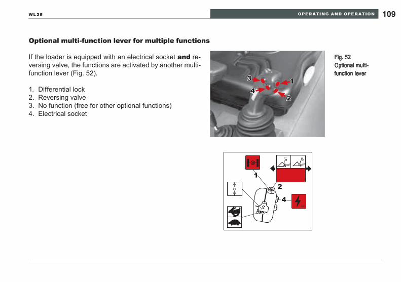
OPER ATING AND OPER ATION 109WL25
Optional multi-function lever for multiple functions
If the loader is equipped with an electrical socket and re-versing valve, the functions are activated by another multi-function lever (Fig. 52).
1. Differential lock2. Reversing valve3. No function (free for other optional functions)4. Electrical socket
Fig. 52 Optional multi-function lever
2
13
4
12V
21
4
TOWING AND TR ANSPORTING110
TOWING AND TRANSPORTING6
Towing6.1
WARNINGPersonal injury or equipment damage hazards from improper towing.
Do not attempt to tow the machine if the steering system or brake system is not serviceable. Loss of control ►during towing can occur. Load the wheel loader and transport it to a repair facility with trained technicians.A tow bar is preferred for towing the wheel loader. Towing straps, cables or chains must be of sufficient capac- ►ity to withstand the energy imparted to the towed machine by the towing source. Inspect the towing device to confirm that it is serviceable and will perform to OSHA ratings for the device.The towing machine must be sufficiently powerful and massive enough to control the towing event. ►Develop a coordinated plan between the towed machine operator and the towing machine operator before ►attempting to start towing. Agree on visual signals if verbal communication is not feasible.Do not begin the tow until all other people are safely away from the towing area in the event an unforeseen ►incident occurs.
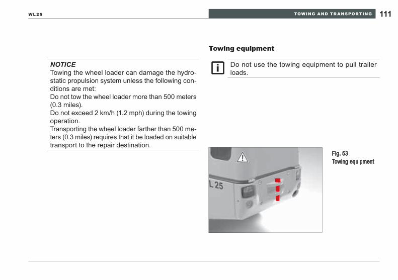
TOWING AND TR ANSPORTING 111WL25
Towing equipment
Fig. 53 Towing equipment
NOTICETowing the wheel loader can damage the hydro-static propulsion system unless the following con-ditions are met:Do not tow the wheel loader more than 500 meters (0.3 miles).Do not exceed 2 km/h (1.2 mph) during the towing operation.Transporting the wheel loader farther than 500 me-ters (0.3 miles) requires that it be loaded on suitable transport to the repair destination.
Do not use the towing equipment to pull trailer loads.
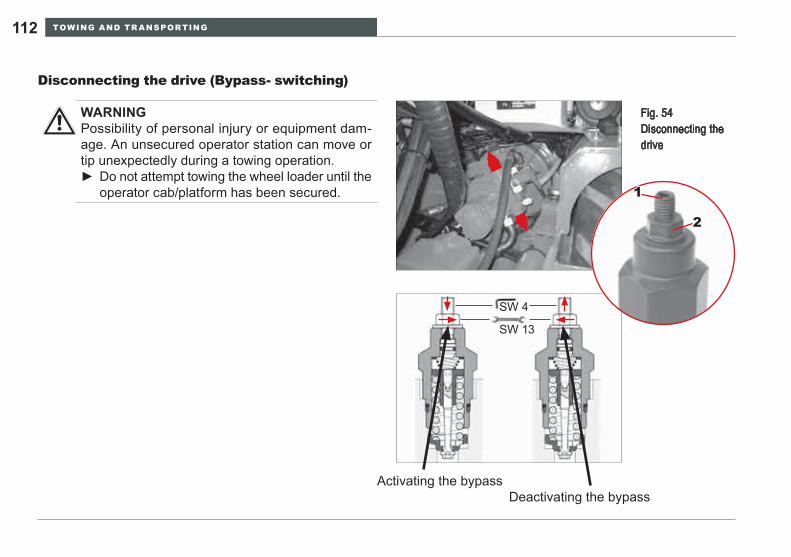
TOWING AND TR ANSPORTING112
Disconnecting the drive (Bypass- switching)
WARNINGPossibility of personal injury or equipment dam-age. An unsecured operator station can move or tip unexpectedly during a towing operation.
Do not attempt towing the wheel loader until the ►operator cab/platform has been secured.
SW 4
SW 13
Fig. 54 Disconnecting the drive
1
2
Activating the bypassDeactivating the bypass
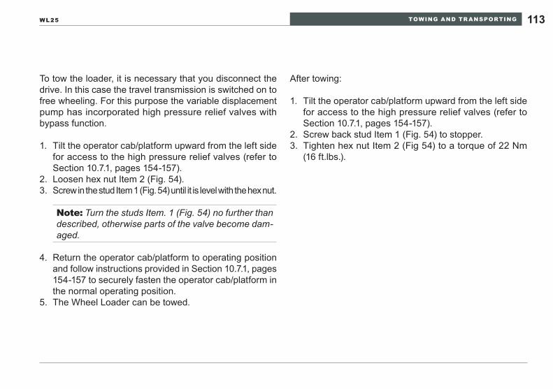
TOWING AND TR ANSPORTING 113WL25
To tow the loader, it is necessary that you disconnect the drive. In this case the travel transmission is switched on to free wheeling. For this purpose the variable displacement pump has incorporated high pressure relief valves with bypass function.
Tilt the operator cab/platform upward from the left side 1. for access to the high pressure relief valves (refer to Section 10.7.1, pages 154-157).Loosen hex nut Item 2 (Fig. 54).2. Screw in the stud Item 1 (Fig. 54) until it is level with the hex nut. 3.
Note: Turn the studs Item. 1 (Fig. 54) no further than described, otherwise parts of the valve become dam-aged.
Return the operator cab/platform to operating position 4. and follow instructions provided in Section 10.7.1, pages 154-157 to securely fasten the operator cab/platform in the normal operating position.The Wheel Loader can be towed.5.
After towing:
Tilt the operator cab/platform upward from the left side 1. for access to the high pressure relief valves (refer to Section 10.7.1, pages 154-157).Screw back stud Item 1 (Fig. 54) to stopper.2. Tighten hex nut Item 2 (Fig 54) to a torque of 22 Nm 3. (16 ft.lbs.).
TOWING AND TR ANSPORTING114
Transporting6.2 Articulation frame lock
Personal injury hazard. Install the articulation frame lock slowly and carefully to reduce the risk of in-jury.The articulation frame lock is stored on the front frame of the wheel loader as illustrated in Fig 55. It is secured by two pins which are retained by spring pins. To install the lock, steer the machine slowly until the hole in the lock aligns with the hole in the rear frame. Insert the pin and retain it with the spring pin.
An articulation frame lock is provided as illustrated in Fig 55 for preventing unintended frame articula-tion during transport.After securely tying the wheel loader to the plat-form of the transport vehicle with OSHA or DOT rated devices for the wheel loader mass, install the articulation joint lock as shown in Fig 55.Reverse the procedure at the point the wheel loader is to be unloaded from the transport.
Load and transport the loader only according to DOT safety regulations.Only experienced, trained specialized personnel may load and transport the loader.
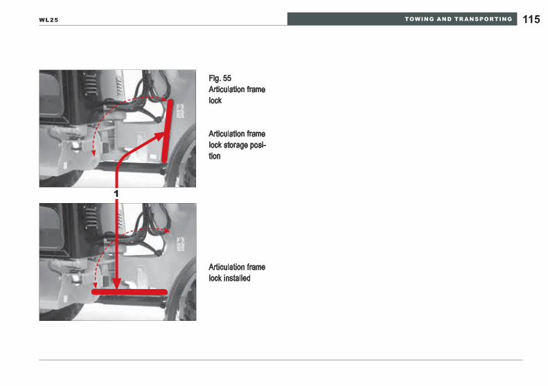
TOWING AND TR ANSPORTING 115WL25
Fig. 55 Articulation frame lock
Articulation frame lock storage posi-tion
Articulation frame lock installed
1
TOWING AND TR ANSPORTING116
Clean the wheel loader to reduce the hazard of dirt and debris falling from the machine during transport.Clean the wheel loader tires, loading ramp and transport vehicle load deck to reduce the slipping hazard during loading.Use a transport vehicle rated to carry the mass of the wheel loader and attachments.Confirm that the transport vehicle is serviceable for the transport task.Move the loader slowly and follow directions from people assisting with loading and alignment on the transport vehicle. Secure the wheel loader to the transport per the instructions in Section 9 »Securing the Loader« on page 125.
WARNINGPossibility of equipment damage or personal injury from improper lifting.
Confirm that the lifting device has adequate ►lifting capacity and reach to perform the lifting operation.Confirm that the lifting devices (slings, cables ►or chains) are OSHA rated for the wheel loader and attachment mass. Confirm that the lifting devices are in service- ►able condition according to the rating.Install the frame articulation lock. ►After completing the lift and correctly positioning ►the wheel loader on the transport, secure the loader using instructions in Section 9 »Securing the Loader« on page 125.
Loading on a transport vehicle Loading with crane
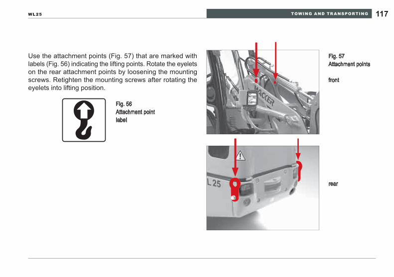
TOWING AND TR ANSPORTING 117WL25
Use the attachment points (Fig. 57) that are marked with labels (Fig. 56) indicating the lifting points. Rotate the eyelets on the rear attachment points by loosening the mounting screws. Retighten the mounting screws after rotating the eyelets into lifting position.
rear
Fig. 56 Attachment point label
Fig. 57 Attachment points
front
TOWING AND TR ANSPORTING118
NOTICEFailure to securely bind the loader to the transport can cause the loader to shift. This can lead to insta-bility in the behavior of the transport or the wheel loader being lost from the transport.Confirm that the articulation frame lock is correctly installed.Use wheel chocks to prevent the loader from slip-ping or rolling away.Tie down the loader only to the special attachment points as depicted in Fig. 60.Use tie down devices with OSHA or DOT ratings for the mass of the wheel loader and attachment.
Clean the wheel loader to reduce the hazard of dirt and debris falling from the machine during transport.Clean the wheel loader tires, loading ramp and transport vehicle load deck to reduce the slipping hazard during loading.Use a transport vehicle rated to carry the mass of the wheel loader and attachments.Confirm that the transport vehicle is serviceable for the transport task.Move the loader slowly and follow directions from people assisting with loading and alignment on the transport vehicle. Install the frame articulation lock.Secure the wheel loader to the transport per the instructions in Section 9 »Securing the Loader« on page 125.
Loader Tie-DownIndependent driving onto the transport device
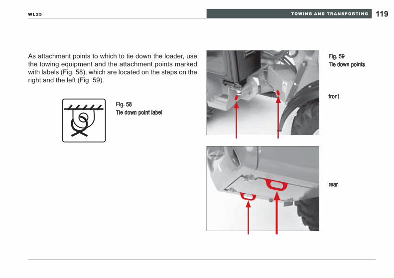
TOWING AND TR ANSPORTING 119WL25
As attachment points to which to tie down the loader, use the towing equipment and the attachment points marked with labels (Fig. 58), which are located on the steps on the right and the left (Fig. 59).
Fig. 58 Tie down point label
Fig. 59 Tie down points
front
rear
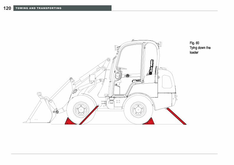
TOWING AND TR ANSPORTING120
Fig. 60 Tying down the loader
LOWERING LOADER ARMS 121WL25
LOWERING LOADER ARMS7
In the event the engine stops and can not be re-started with the loader lift arms elevated:
Lower the loader lift arms and attachment until • they rest on the ground or work surface.
The same procedure shall be used if the hydrostatic propulsion system stops responding.
In the event of a working hydraulic system failure: Lower the loader lift arms and attachment as • quickly and safely as possible.
If a hydraulic hose fails: Avoid contact with the oil stream. Working hy-• draulic oil can exceed 93°C (200°F) causing severe burns. High pressure oil streams can penetrate the skin causing serious injury.Relieve working circuit pressure by activating • the control through the full stroke range several times.
Loaders equipped with a load holding control device in compliance with ISO8643 will stop the loader lift arms from falling more than 15cm (6”) before stop-ping if a hose or hydraulic line suffers a rupture and rapid leak. Refer to Section 8 »Relieving residual pressure in the hydraulic system« on page 122.
RELIEVING RESIDUAL PRESSURE IN THE HYDRAULIC SYSTEM122
RELIEVING RESIDUAL PRESSURE IN THE HYDRAULIC SYSTEM8
Proceed as follows to reduce the residual pressure in the hydraulic circuits (adhere to the order of the individual work steps):
Lower the loader lift arms as far as 1. they will go.Turn off the engine.2. Immediately after turning off the engine, actuate all the 3. control levers and pedals for the hydraulic system several times in all directions.Relieve the hydraulic tank by opening the filler neck, 4. illustration 1 (Fig. 61).Remove the preload from the drive‘s system by opening 5. the return filter, illustration 2 (Fig. 61).
WARNINGPersonal injury hazard.A fine jet of hydraulic fluid under high pressure can pierce the skin. Seek medical assistance im-mediately if you get hydraulic fluid in your eyes or on your skin.
Open only unpressurized hydraulic systems. ►Residual hydraulic pressure can still be present in the working hydraulic circuits after the loader lift arms and attachment are resting on the ground or working surface.
Do not attempt repair work on hydraulic cir- ►cuits until the temperature of the components is comfortable to touch (typically less than 49°C (120°F)).
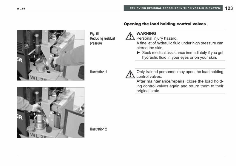
RELIEVING RESIDUAL PRESSURE IN THE HYDRAULIC SYSTEM 123WL25
Fig. 61 Reducing residual pressure
Illustration 1
Illustration 2
Opening the load holding control valves
WARNINGPersonal injury hazard.A fine jet of hydraulic fluid under high pressure can pierce the skin.
Seek medical assistance immediately if you get ►hydraulic fluid in your eyes or on your skin.
Only trained personnel may open the load holding control valves.After maintenance/repairs, close the load hold-ing control valves again and return them to their original state.
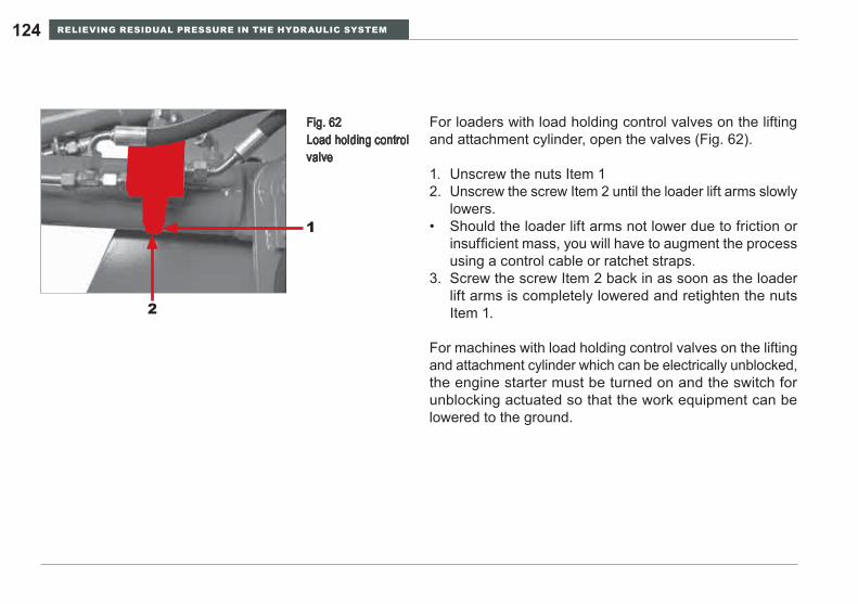
RELIEVING RESIDUAL PRESSURE IN THE HYDRAULIC SYSTEM124
For loaders with load holding control valves on the lifting and attachment cylinder, open the valves (Fig. 62).
Unscrew the nuts Item 11. Unscrew the screw Item 2 until the loader lift arms slowly 2. lowers.Should the loader lift arms not lower due to friction or • insufficient mass, you will have to augment the process using a control cable or ratchet straps.Screw the screw Item 2 back in as soon as the loader 3. lift arms is completely lowered and retighten the nuts Item 1.
For machines with load holding control valves on the lifting and attachment cylinder which can be electrically unblocked, the engine starter must be turned on and the switch for unblocking actuated so that the work equipment can be lowered to the ground.
Fig. 62 Load holding control valve
2
1
SECURING THE LOADER 125WL25
SECURING THE LOADER9
The following instructions apply to stopping and parking the loader after daily operation, transport-ing the loader and to all servicing, inspection and repair work.
Place the loader on an even, dry surface that can sup-• port sufficient weight.Lower the loader lift arms.• Engage the parking brake and stop the engine.• Switch off all electrical switches.• Relieve the pressure in all hydraulic circuits by cycling • the controls after the engine has stopped.Secure the loader with the wheel chock.• Clean dirt off the loader.• Perform a visual inspection to make sure there are no • leaks:
in the hydraulic system -in the cooling system -in the fuel system -
Perform a visual inspection for damage to the loader, • especially on the tires, attachments and locking mecha-nism for the attachments.Fill the fuel tank and check the operating level of the • other fluid reservoirs after the temperature has been reduced to a level that is comfortable to touch.Secure the loader against unauthorized use:•
Remove the starting key -Close the windows, doors, tank lid and engine hood. -
SERVICING AND INSPECTION126
SERVICING AND INSPECTION10
Basic safety instructions for servicing and inspection10.1
Operator’s manual
Perform servicing and inspection work only if you have • read and understood the operator’s manual.Observe the basic safety instructions and all the warning • signs attached to the loader.The operator’s manual describes the work to be per-• formed. However, the descriptions of work processes provide the necessary instructions only for experienced specialized technicians.Keep the operator’s manual with the loader at all • times.
Personnel
Maintenance and inspection personnel must have spe-• cialized knowledge of servicing and inspection work on the loader. The specialized knowledge required can be obtained at training sessions from Wacker Neuson Service.Perform servicing and inspection work only with suitable • work clothing and personal protective equipment.Wear hearing protection should there be noise exceed-• ing 90 dbA.
SERVICING AND INSPECTION 127WL25
Securing the loader and attachment
Carry out servicing and inspection work only if the loader is secured as described in the chapter »Securing • the loader«.Crushing hazard. An improperly supported loader lift arm may fall unexpectedly. • Do not perform maintenance or service tasks under raised loader lift arms until the loader lift arm support • device (ISO105330 has been inserted and locked between the hydraulic lift cylinder end and the loader lift arm to prevent any movement of the loader lift arms during maintenance and service.Extensive repair information is provided in the separate Repair Manual.• Position the attachments on the ground so that no movements can occur when mechanical or hydraulic con-• nections are released.Do not attempt any service repair requiring the technician to perform the work standing in the articulated • steering crush zone. Do not repair the hydraulic steering cylinders or remove the hydraulic lines until the articulated frame lock has been installed to prevent inadvertent steering movement.Secure equipment or components that are to be attached or removed, or whose installation position is to be • changed, to prevent them from unintentionally moving, slipping or falling, by means of suitable lifting gear, or suspension or support equipment.Clean dirt from steps and handles and keep them ready for use.•
SERVICING AND INSPECTION128
Tools
Use diagnostic and repair tools that are in serviceable • condition and have been calibrated regularly to ensure accuracy. Consult the Repair Manual for recommended special tools necessary to safely complete the repair task.
Cleaning
Clean the machine before attempting to diag-• nose or repair the wheel loader.Do not use flammable solvents. • Do not use cleaning agents that create harmful • vapors. Avoid any contact with electrical or rubber prod-• ucts when using water or steam. High pressure washers are not recommended • for cleaning the inside of the cab or the opera-tor station.Wear appropriate protective clothing such as • goggles and gloves to supplement protective clothing for the rest of the body.
Handling combustible fluids
Do not smoke when handling combustible fluids • and avoid fire or open flames.Do not use water to extinguish fires on the load-• er or burning fluids. Use suitable extinguishing agents, such as powder, carbon dioxide or foam extinguishers.Always call the fire department in the event of • a fire.
SERVICING AND INSPECTION 129WL25
Residual pressure in the hydraulic system
Personal injury hazard.Pressurized jets of fluid can penetrate human skin. • In the event that oil penetrates the skin, seek immediate medical attention to reduce the risk of infection and • complications from infection.Confirm that the hydraulic system is pressure has been relieved before attempting to repair the system or • component.Even for a loader parked on a horizontal surface with its loader lift arms completely lowered and engine turned • off, there can still be considerable residual pressure in parts of the hydraulic system.Residual pressure reduces gradually at first. If a hydraulic system is to be opened immediately after being • shut down, the system shall be relieved before repairs are attempted. Do not attempt to work on the system if the components are not comfortable to touch. Hot surfaces and liquids can cause severe burns.For loaders with load holding control devices on the lifting and/or tipping cylinder, you must open the valves • as described in Section 8, page 122 »Relieving residual pressure in the hydraulic system« in order to lower the loader lift arms.
SERVICING AND INSPECTION130
Threaded connections, pipes, hydraulic hoses
WARNINGPersonal injury hazard.
Pressurized jets of fluid can penetrate human • skin. In the event that oil penetrates the skin, seek • immediate medical attention to reduce the risk of of infection and complications from infection.Do not use your hands to look for leaks. To look • for leaks, use a piece of cardboard or paper on which you can identify oil which has escaped.
Eliminate any leaks in the hydraulic fittings, hoses or • steel conduits immediately.Do not repair damaged pipes and hydraulic hoses; rather, • replace them immediately with new ones available from your Wacker Neuson dealer even if only moisture pen-etration is visible.
Burn hazard.The operating temperature of the engine and • hydraulic system fluids exceeds 93°C (200°F). Contact with human skin will cause severe burns. Do not touch hot fluid. • In the event of contact with hot fluid seek emer-• gency room treatment immediately.Avoid skin and eye contact with oils and greases. • Wear protective gloves and safety goggles.Do not use fuel or solvents to clean your skin.• Eliminate any oil or fuel leaks immediately.• Avoid environmental damage. Do not allow oil • and oil-containing waste to spill on the ground or get into bodies of water!Immediately soak up with binding material any • oil or fuel that has leaked, and dispose of it separately from other waste in an ecologically sound manner.Even biodegradable »environmentally friendly« • oil must be disposed of separately, just like other oil.
Handling fuel, oil and grease
SERVICING AND INSPECTION 131WL25
Batteries
Explosion hazard.A rapidly discharged battery vents explosive gas-es.
Do not use open flames or smoke near batter-• ies. -Use particular caution to vent the battery storage area well to avoid gas accumulation.Follow jump start procedures to reduce the po-• tential for arcing when the cables are connected and disconnected.Do not place metallic objects on or near the • battery terminals to avoid short circuits from contact with both poles of the battery. This will generate extreme heat and potentially ignite explosive battery gases.
Personal injury hazard. Battery acid is corrosive to metallic surfaces and harmful to human skin.
Wear protective clothing, goggles and gloves • when working near batteries.If battery acid contacts the skin, wash immedi-• ately in clear water.Seek the advice of a doctor for treatment of • skin burns.In the event acid contacts eyes, rinse imme-• diately with clear water and seek immediate medical attention.
Always take off jewelry and metal watches before work-• ing on the battery or the electrical system.Dispose of old batteries in an ecologically sound way, • separate from other waste.
SERVICING AND INSPECTION132
Electrical system
Always observe the correct order when disconnecting • the battery.
Disconnecting: First the negative pole and then the posi- -tive pole.Connecting: First the positive pole and then the nega- -tive pole.
Always disconnect the battery before working on the • electrical system if tools, spare parts, etc. with electrical components or contacts could touch it.Always disconnect the battery before welding.•
Diesel engine exhaust fumes are harmful. Do • not inhale exhaust gas. Do not operate the wheel loader in a closed space.For servicing and inspection work performed • in a closed space, extract the exhaust fumes using an extraction system and ventilate the space well.
Engine exhaust fumes
SERVICING AND INSPECTION 133WL25
After maintenance
After completing maintenance and inspection work, al-• ways reattach all the safety devices.Do not start the engine until the loader is no longer being • worked on and everyone has left the danger area.Only start the engine from the operator’s seat.• Perform a functional test with the loader after completing • servicing and inspection work.
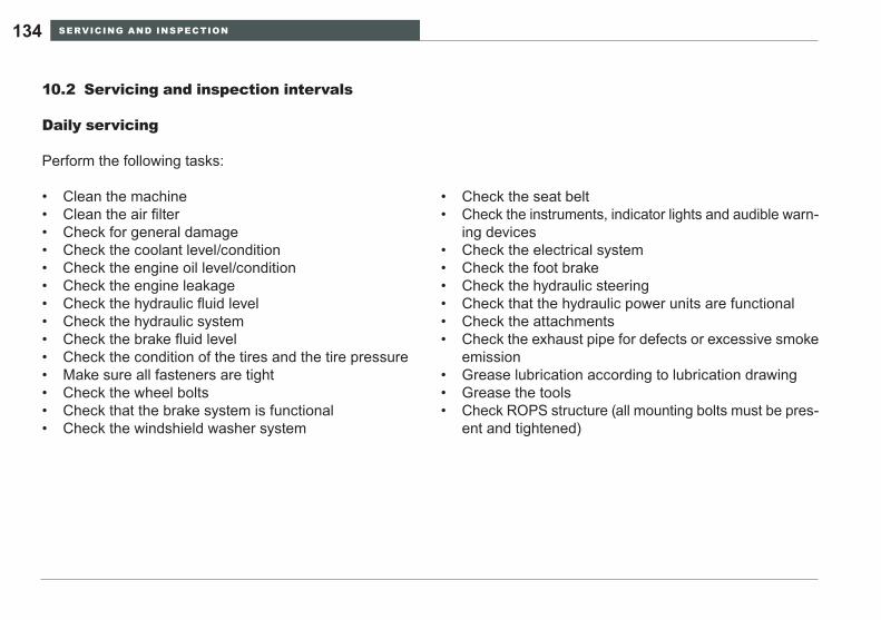
SERVICING AND INSPECTION134
Servicing and inspection intervals10.2
Daily servicing
Perform the following tasks:
Clean the machine• Clean the air filter• Check for general damage• Check the coolant level/condition• Check the engine oil level/condition• Check the engine leakage• Check the hydraulic fluid level• Check the hydraulic system• Check the brake fluid level• Check the condition of the tires and the tire pressure• Make sure all fasteners are tight• Check the wheel bolts• Check that the brake system is functional• Check the windshield washer system•
Check the seat belt• Check the instruments, indicator lights and audible warn-• ing devicesCheck the electrical system• Check the foot brake• Check the hydraulic steering• Check that the hydraulic power units are functional• Check the attachments• Check the exhaust pipe for defects or excessive smoke • emissionGrease lubrication according to lubrication drawing• Grease the tools• Check ROPS structure (all mounting bolts must be pres-• ent and tightened)
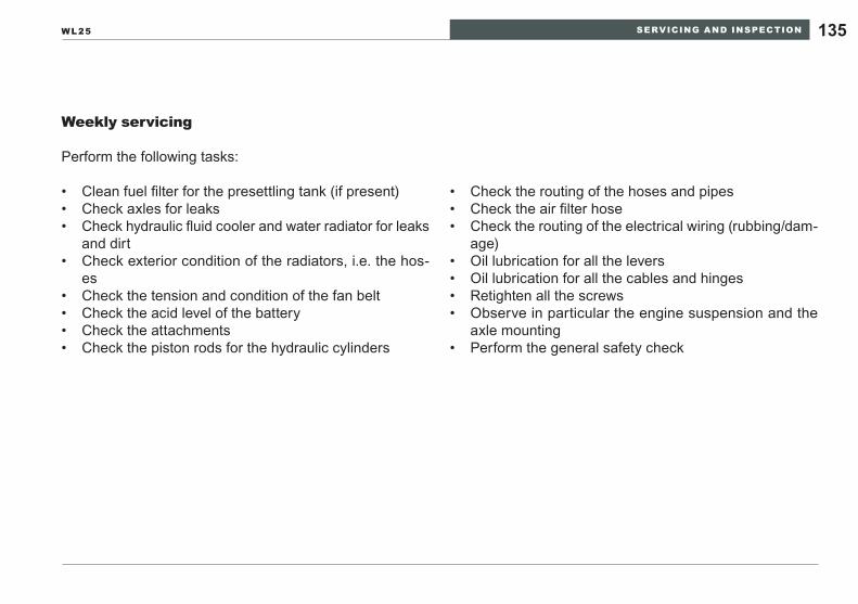
SERVICING AND INSPECTION 135WL25
Weekly servicing
Perform the following tasks:
Clean fuel filter for the presettling tank (if present)• Check axles for leaks• Check hydraulic fluid cooler and water radiator for leaks • and dirtCheck exterior condition of the radiators, i.e. the hos-• esCheck the tension and condition of the fan belt• Check the acid level of the battery• Check the attachments• Check the piston rods for the hydraulic cylinders•
Check the routing of the hoses and pipes• Check the air filter hose• Check the routing of the electrical wiring (rubbing/dam-• age)Oil lubrication for all the levers• Oil lubrication for all the cables and hinges• Retighten all the screws• Observe in particular the engine suspension and the • axle mountingPerform the general safety check•
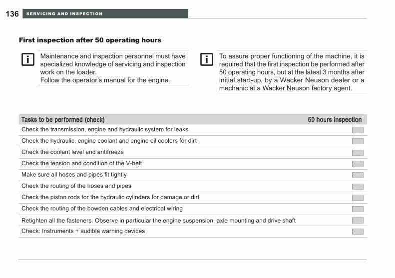
SERVICING AND INSPECTION136
First inspection after 50 operating hours
Tasks to be performed (check) 50 hours inspectionCheck the transmission, engine and hydraulic system for leaks
Check the hydraulic, engine coolant and engine oil coolers for dirt
Check the coolant level and antifreeze
Check the tension and condition of the V-belt
Make sure all hoses and pipes fit tightly
Check the routing of the hoses and pipes
Check the piston rods for the hydraulic cylinders for damage or dirt
Check the routing of the bowden cables and electrical wiring
Retighten all the fasteners. Observe in particular the engine suspension, axle mounting and drive shaft
Check: Instruments + audible warning devices
Maintenance and inspection personnel must have specialized knowledge of servicing and inspection work on the loader.Follow the operator’s manual for the engine.
To assure proper functioning of the machine, it is required that the first inspection be performed after 50 operating hours, but at the latest 3 months after initial start-up, by a Wacker Neuson dealer or a mechanic at a Wacker Neuson factory agent.
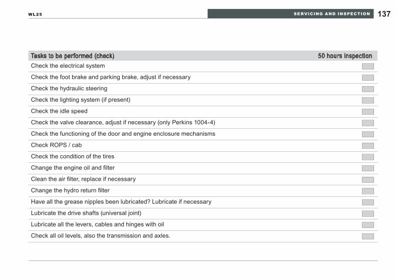
SERVICING AND INSPECTION 137WL25
Tasks to be performed (check) 50 hours inspectionCheck the electrical system
Check the foot brake and parking brake, adjust if necessary
Check the hydraulic steering
Check the lighting system (if present)
Check the idle speed
Check the valve clearance, adjust if necessary (only Perkins 1004-4)
Check the functioning of the door and engine enclosure mechanisms
Check ROPS / cab
Check the condition of the tires
Change the engine oil and filter
Clean the air filter, replace if necessary
Change the hydro return filter
Have all the grease nipples been lubricated? Lubricate if necessary
Lubricate the drive shafts (universal joint)
Lubricate all the levers, cables and hinges with oil
Check all oil levels, also the transmission and axles.
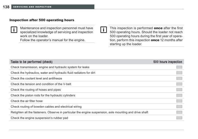
SERVICING AND INSPECTION138
Inspection after 500 operating hours
Tasks to be performed (check) 500 hours inspectionCheck transmission, engine and hydraulic system for leaks
Check the hydraulics, water and hydraulic fluid radiators for dirt
Check the coolant level and antifreeze
Check the tension and condition of the V-belt
Check the routing of hoses and pipes
Check the piston rods for the hydraulic cylinders
Check the air filter hose
Check routing of bowden cables and electrical wiring
Retighten all the fasteners. Observe in particular the engine suspension, axle mounting and drive shaft
Check the engine suspension‘s rubber pad
Maintenance and inspection personnel must have specialized knowledge of servicing and inspection work on the loader.Follow the operator’s manual for the engine.
This inspection is performed once after the first 500 operating hours. Should the loader not reach 500 operating hours during the first year of opera-tion, perform this inspection once 12 months after starting up the loader.
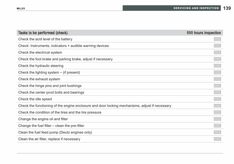
SERVICING AND INSPECTION 139WL25
Tasks to be performed (check) 500 hours inspectionCheck the acid level of the battery
Check: Instruments, indicators + audible warning devices
Check the electrical system
Check the foot brake and parking brake, adjust if necessary
Check the hydraulic steering
Check the lighting system – (if present)
Check the exhaust system
Check the hinge pins and joint bushings
Check the center pivot bolts and bearings
Check the idle speed
Check the functioning of the engine enclosure and door locking mechanisms, adjust if necessary
Check the condition of the tires and the tire pressure
Change the engine oil and filter
Change the fuel filter – clean the pre-filter
Clean the fuel feed pump (Deutz engines only)
Clean the air filter, replace if necessary
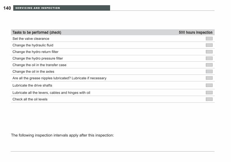
SERVICING AND INSPECTION140
Tasks to be performed (check) 500 hours inspectionSet the valve clearance
Change the hydraulic fluid
Change the hydro return filter
Change the hydro pressure filter
Change the oil in the transfer case
Change the oil in the axles
Are all the grease nipples lubricated? Lubricate if necessary
Lubricate the drive shafts
Lubricate all the levers, cables and hinges with oil
Check all the oil levels
The following inspection intervals apply after this inspection:
SERVICING AND INSPECTION 141WL25
Inspection intervals
Maintenance and inspection personnel must have specialized knowledge of servicing and inspection work on the loader.Follow the operator’s manual for the engine.Perform the maintenance work listed in the inspec-tion schedule depending on which interval has been reached first, that is, if either the number of operat-ing hours have been reached or the time specified in the schedule has elapsed.At the end of the operator’s manual you will find the form »Inspection verification«, in which the inspec-tions to be performed must be recorded.
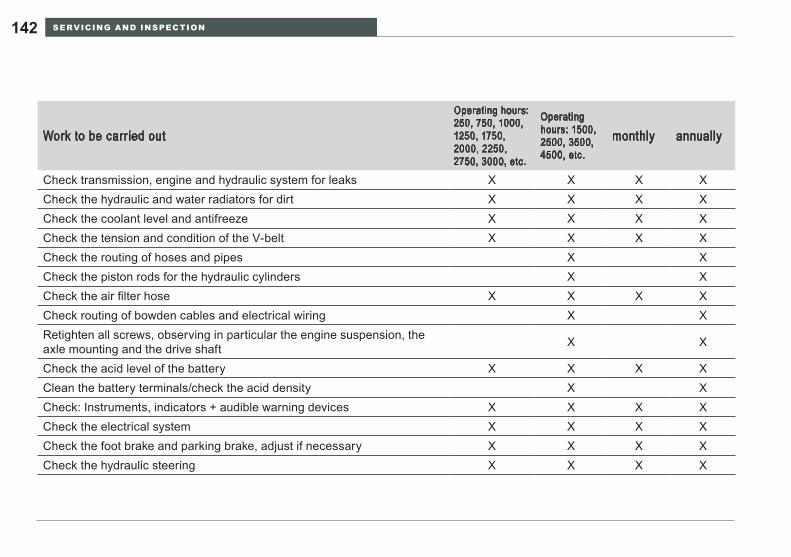
SERVICING AND INSPECTION142
Work to be carried out
Operating hours: 250, 750, 1000, 1250, 1750, 2000, 2250, 2750, 3000, etc.
Operating hours: 1500, 2500, 3500, 4500, etc.
monthly annually
Check transmission, engine and hydraulic system for leaks x x x xCheck the hydraulic and water radiators for dirt x x x xCheck the coolant level and antifreeze x x x xCheck the tension and condition of the V-belt x x x xCheck the routing of hoses and pipes x xCheck the piston rods for the hydraulic cylinders x xCheck the air filter hose x x x xCheck routing of bowden cables and electrical wiring x xRetighten all screws, observing in particular the engine suspension, the axle mounting and the drive shaft x x
Check the acid level of the battery x x x xClean the battery terminals/check the acid density x xCheck: Instruments, indicators + audible warning devices x x x xCheck the electrical system x x x xCheck the foot brake and parking brake, adjust if necessary x x x xCheck the hydraulic steering x x x x
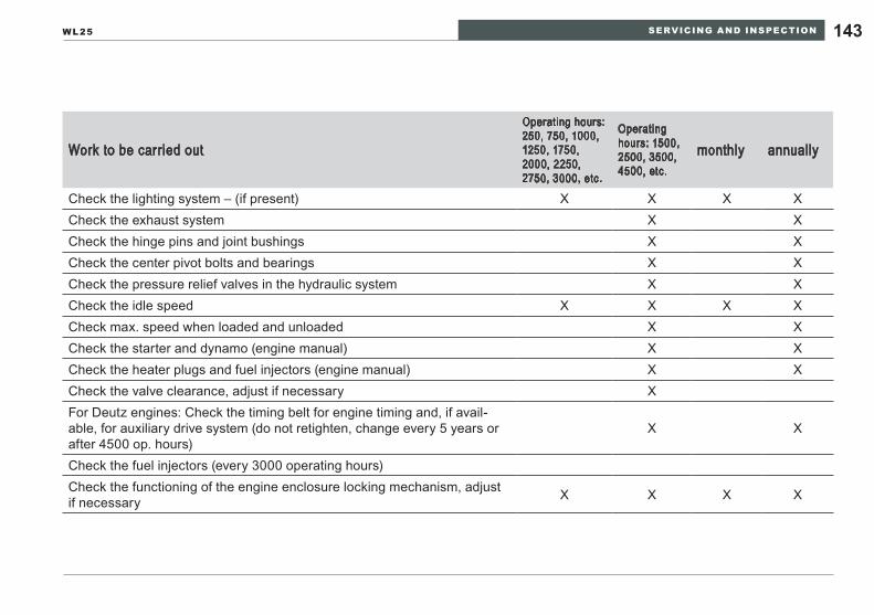
SERVICING AND INSPECTION 143WL25
Work to be carried out
Operating hours: 250, 750, 1000, 1250, 1750, 2000, 2250, 2750, 3000, etc.
Operating hours: 1500, 2500, 3500, 4500, etc.
monthly annually
Check the lighting system – (if present) x x x xCheck the exhaust system x xCheck the hinge pins and joint bushings x xCheck the center pivot bolts and bearings x xCheck the pressure relief valves in the hydraulic system x xCheck the idle speed x x x xCheck max. speed when loaded and unloaded x xCheck the starter and dynamo (engine manual) x xCheck the heater plugs and fuel injectors (engine manual) x xCheck the valve clearance, adjust if necessary xFor Deutz engines: Check the timing belt for engine timing and, if avail-able, for auxiliary drive system (do not retighten, change every 5 years or after 4500 op. hours)
x x
Check the fuel injectors (every 3000 operating hours)Check the functioning of the engine enclosure locking mechanism, adjust if necessary x x x x
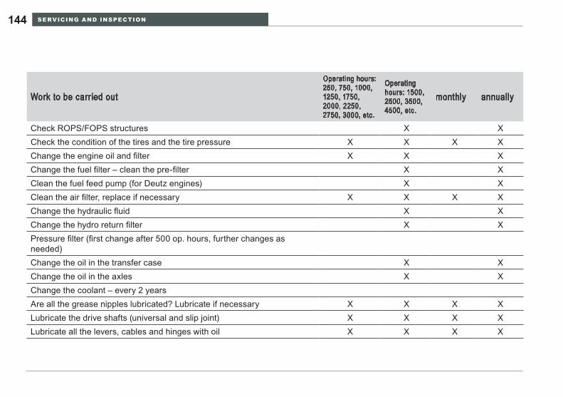
SERVICING AND INSPECTION144
Work to be carried out
Operating hours: 250, 750, 1000, 1250, 1750, 2000, 2250, 2750, 3000, etc.
Operating hours: 1500, 2500, 3500, 4500, etc.
monthly annually
Check ROPS/FOPS structures x xCheck the condition of the tires and the tire pressure x x x xChange the engine oil and filter x x xChange the fuel filter – clean the pre-filter x xClean the fuel feed pump (for Deutz engines) x xClean the air filter, replace if necessary x x x xChange the hydraulic fluid x xChange the hydro return filter x xPressure filter (first change after 500 op. hours, further changes as needed)Change the oil in the transfer case x xChange the oil in the axles x xChange the coolant – every 2 yearsAre all the grease nipples lubricated? Lubricate if necessary x x x xLubricate the drive shafts (universal and slip joint) x x x xLubricate all the levers, cables and hinges with oil x x x x
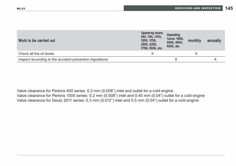
SERVICING AND INSPECTION 145WL25
Work to be carried out
Operating hours: 250, 750, 1000, 1250, 1750, 2000, 2250, 2750, 3000, etc.
Operating hours: 1500, 2500, 3500, 4500, etc.
monthly annually
Check all the oil levels x xInspect according to the accident prevention regulations x x
Valve clearance for Perkins 400 series: 0.2 mm (0.008”) inlet and outlet for a cold engineValve clearance for Perkins 1000 series: 0.2 mm (0.008”) inlet and 0.45 mm (0.04”) outlet for a cold engineValve clearance for Deutz 2011 series: 0.3 mm (0.012”) inlet and 0.5 mm (0.04”) outlet for a cold engine
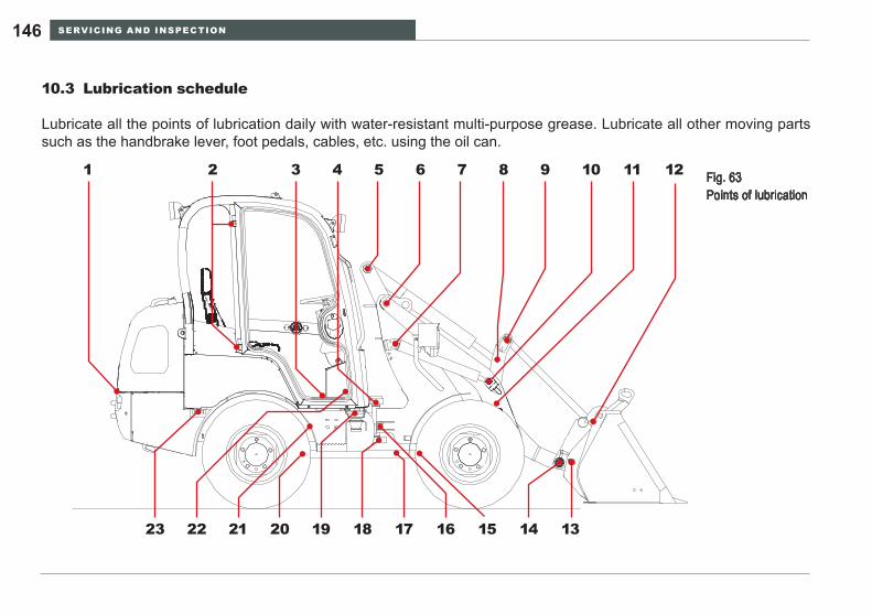
SERVICING AND INSPECTION146
Lubrication schedule10.3
Lubricate all the points of lubrication daily with water-resistant multi-purpose grease. Lubricate all other moving parts such as the handbrake lever, foot pedals, cables, etc. using the oil can.
Fig. 63 Points of lubrication
1 2 3 4 5 6 7 8 9 10 11 12
23 22 21 20 19 18 17 16 15 14 13
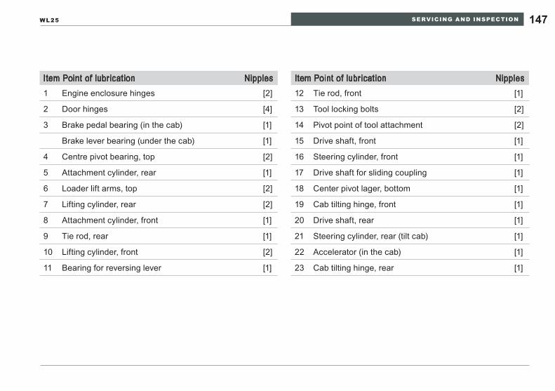
SERVICING AND INSPECTION 147WL25
Item Point of lubrication Nipples 12 Tie rod, front [1]
13 Tool locking bolts [2]
14 Pivot point of tool attachment [2]
15 Drive shaft, front [1]
16 Steering cylinder, front [1]
17 Drive shaft for sliding coupling [1]
18 Center pivot lager, bottom [1]
19 Cab tilting hinge, front [1]
20 Drive shaft, rear [1]
21 Steering cylinder, rear (tilt cab) [1]
22 Accelerator (in the cab) [1]
23 Cab tilting hinge, rear [1]
Item Point of lubrication Nipples 1 Engine enclosure hinges [2]
2 Door hinges [4]
3 Brake pedal bearing (in the cab) [1]
Brake lever bearing (under the cab) [1]
4 Centre pivot bearing, top [2]
5 Attachment cylinder, rear [1]
6 Loader lift arms, top [2]
7 Lifting cylinder, rear [2]
8 Attachment cylinder, front [1]
9 Tie rod, rear [1]
10 Lifting cylinder, front [2]
11 Bearing for reversing lever [1]
SERVICING AND INSPECTION148
Cleaning the loader10.4
WARNINGBurn hazard.High pressure water at this temperature will cause severe burns and is extremely hazardous if contact is made with the eyes.
Wear protective clothing and safety goggles ►while cleaning the machine.
NOTICEWhen cleaning the loader, pay particular atten-• tion to its underside. Do not allow mud to collect on the engine and transmission.Make sure that the radiator is thoroughly clean • all over.Do not damage the radiator fins when cleaning • the radiator with a high-pressure cleaner.Always cover up the suction connection of the • air filter before washing the engine.Do not clean sensitive electrical components • (instrument panel, dynamo, compact plug, multi-function lever, etc.) with a high-pressure cleaner.
Clean the wheel loader frequently, particularly the access systems, to prevent slips and falls when entering and leaving the operator station.To avoid potential fires, remove flammable debris and dust from the hot surfaces in the engine en-closure and hydraulic system.
SERVICING AND INSPECTION 149WL25
eNVIRONmeNTAl NOTeAvoid environmental damage.Clean the loader only in a suitable place where the waste water can be collected in an ecologically sound manner.Collect contaminated waste water and dispose of it in an ecologically sound manner.
When the loader is new (in the first three months), only clean it with a sponge.As the paintwork on the underside is not fully hard-ened, the paintwork can be damaged if cleaned with a high-pressure cleaner.Please note when cleaning the loader with a high-pressure cleaner:Maximum water pressure 130 bar (1885 psi).Maximum water temperature 80°C (176°F).When cleaning, do not hold the jets of the high-pressure cleaner too close to the labels and other sensitive parts, so that nothing gets damaged.
SERVICING AND INSPECTION150
General safety check10.5
Check:
all steel parts for damaged and loose screws/bolts, par-• ticularly the ROPS structure,the condition of the seat belt,• the quick-change system for the attachments,• that all the hinge pins are in the correct position and are • secured by their locking devices,that the step and handles are in good condition, clean • and fit well,cab windows for cracks and fractures,• the condition of the reflectors and the lighting, including • the work lights,the tires for damage and any sharp-edged objects that • have penetrated them,the condition of all warning and message labels.•
Immediately rectify any damage detected during the safety check. Damaged parts must be imme-diately repaired or replaced. Do not use the loader again until the damage has been rectified profes-sionally.
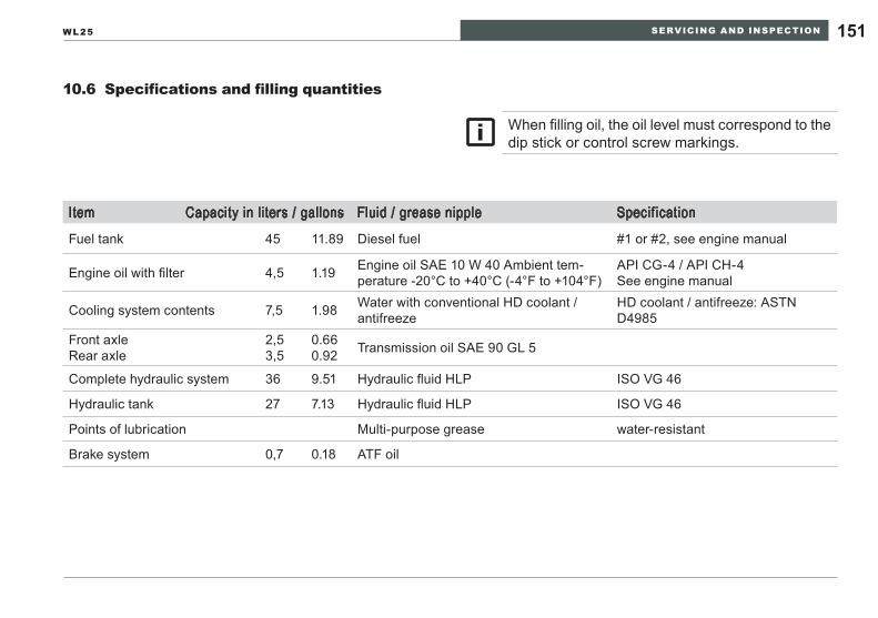
SERVICING AND INSPECTION 151WL25
Specifications and filling quantities10.6
Item Capacity in liters / gallons Fluid / grease nipple Specif ication
Fuel tank 45 11.89 Diesel fuel #1 or #2, see engine manual
Engine oil with filter 4,5 1.19 Engine oil SAE 10 W 40 Ambient tem-perature -20°C to +40°C (-4°F to +104°F)
API CG-4 / API CH-4See engine manual
Cooling system contents 7,5 1.98 Water with conventional HD coolant / antifreeze
HD coolant / antifreeze: ASTN D4985
Front axleRear axle
2,53,5
0.660.92 Transmission oil SAE 90 GL 5
Complete hydraulic system 36 9.51 Hydraulic fluid HLP ISO VG 46
Hydraulic tank 27 7.13 Hydraulic fluid HLP ISO VG 46
Points of lubrication Multi-purpose grease water-resistant
Brake system 0,7 0.18 ATF oil
When filling oil, the oil level must correspond to the dip stick or control screw markings.
SERVICING AND INSPECTION152
Maintenance and inspection work10.7 Preparation for maintenance and inspection 10.7.1 work
Opening the engine enclosurePerform maintenance and inspection work only if the loader is secured as described in Section 9, page 125 »Securing the loader«.The operator cab/platform can be tilted for access to the wheel loader systems for inspection, main-tenance and repair. Refer to section 10.7.1. pages 154-157 for detailed instructions on how to tilt the operator cab/platform.
WARNINGCrushing/shearing hazard.Moving engine parts can crush and cut.
Do not open the engine enclosure unless the ►engine is stopped to avoid hazards from moving objects (cooling fan and drive belts for the fan and alternator).
Burn hazard.Engine components can get very hot during op-eration.
Do not touch the engine mass, exhaust system, ►or cooling system immediately after stopping the engine.Wait until the stopped engine has cooled to the ►point that the exhaust system, engine mass and cooling system are comfortable to touch..
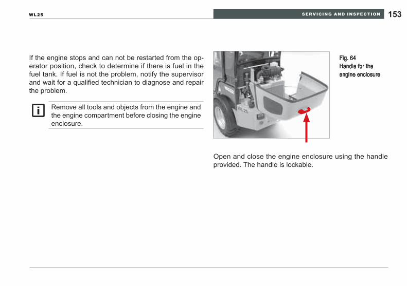
SERVICING AND INSPECTION 153WL25
Open and close the engine enclosure using the handle provided. The handle is lockable.
Fig. 64 Handle for the engine enclosure
If the engine stops and can not be restarted from the op-erator position, check to determine if there is fuel in the fuel tank. If fuel is not the problem, notify the supervisor and wait for a qualified technician to diagnose and repair the problem.
Remove all tools and objects from the engine and the engine compartment before closing the engine enclosure.
SERVICING AND INSPECTION154
Tilting the operator’s platform
WARNINGImproperly tilting the cab can cause personal injury or damage to equipment.
Before tilting the cab remove loose objects from ►the cab to avoid control/indicator damage.Close and confirm that the doors are latched ►Do not attempt to tilt the cab until the wheel load- ►er has cooled to the point that the engine and hydraulic system are comfortable to touch.Do not remove the bearing plate from the loader ►rear frame member.Do not operate the wheel loader until the cab ►has been rigidly bolted to the main frame.Tilt the cab slowly and keep hands and arms ►clear of pinch points.
NOTICE: Avoid damage to the cab doors.Either close the doors or remove them.
To facilitate tilting of the operator’s platform, there is a lever, item 1, under the engine enclosure (Fig. 65). To tilt the operator’s platform, place the lever in the holder, item 2 (Fig. 65).
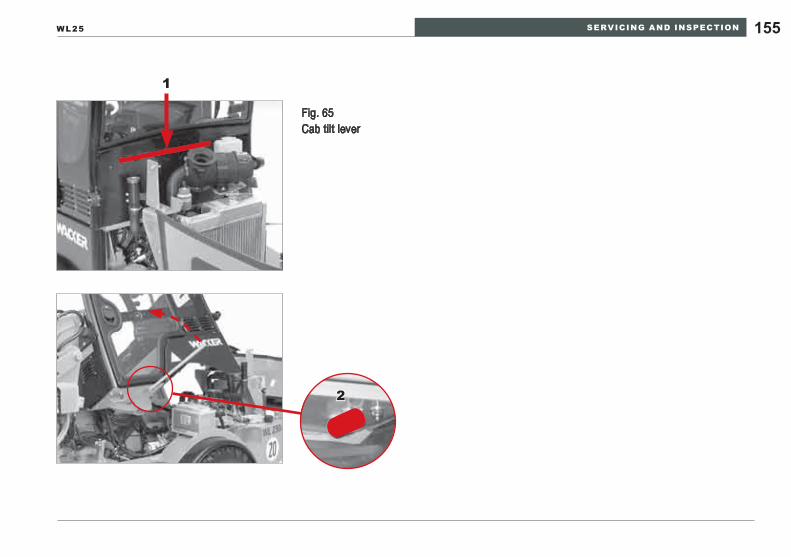
SERVICING AND INSPECTION 155WL25
Fig. 65 Cab tilt lever
1
2
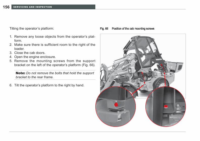
SERVICING AND INSPECTION156
Tilting the operator’s platform: Position of the cab mounting screwsFig. 66
Remove any loose objects from the operator’s plat-1. form.Make sure there is sufficient room to the right of the 2. loader.Close the cab doors.3. Open the engine enclosure.4. Remove the mounting screws from the support 5. bracket on the left of the operator’s platform (Fig. 66).
Note: Do not remove the bolts that hold the support bracket to the rear frame.
Tilt the operator’s platform to the right by hand.6.
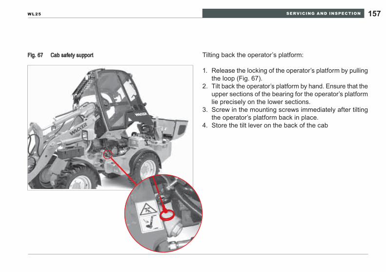
SERVICING AND INSPECTION 157WL25
Tilting back the operator’s platform:Cab safety supportFig. 67
Release the locking of the operator’s platform by pulling 1. the loop (Fig. 67).Tilt back the operator’s platform by hand. Ensure that the 2. upper sections of the bearing for the operator’s platform lie precisely on the lower sections.Screw in the mounting screws immediately after tilting 3. the operator’s platform back in place.Store the tilt lever on the back of the cab4.
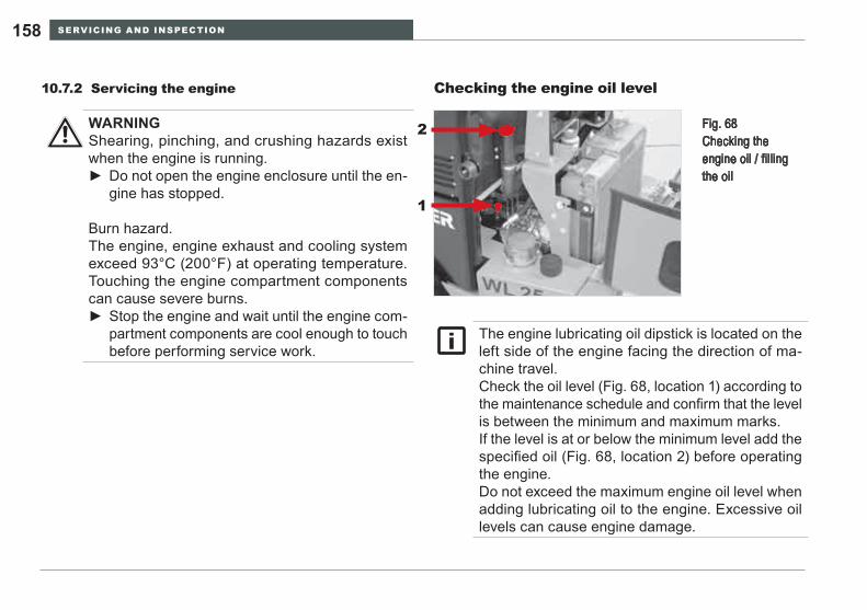
SERVICING AND INSPECTION158
Servicing the engine10.7.2 Checking the engine oil level
WARNINGShearing, pinching, and crushing hazards exist when the engine is running.
Do not open the engine enclosure until the en- ►gine has stopped.
Burn hazard.The engine, engine exhaust and cooling system exceed 93°C (200°F) at operating temperature. Touching the engine compartment components can cause severe burns.
Stop the engine and wait until the engine com- ►partment components are cool enough to touch before performing service work.
The engine lubricating oil dipstick is located on the left side of the engine facing the direction of ma-chine travel. Check the oil level (Fig. 68, location 1) according to the maintenance schedule and confirm that the level is between the minimum and maximum marks. If the level is at or below the minimum level add the specified oil (Fig. 68, location 2) before operating the engine. Do not exceed the maximum engine oil level when adding lubricating oil to the engine. Excessive oil levels can cause engine damage.
Fig. 68 Checking the engine oil / filling the oil
2
1
SERVICING AND INSPECTION 159WL25
Adding engine oil
If the fluid level is under the »Maximum« mark, the fluid must be added:
Stop the loader on a horizontal surface and set the park-1. ing brake.Lower the loader lift arms and attachment to the ground 2. or working surface.Stop the engine.3. Wait until the engine has cooled and the dipstick is com-4. fortable to touch.Open the engine enclosure.5. Pull out the dip stick (left side of the engine; Item 1 Fig. 6. 68).Wipe the dip stick with a clean, lint-free cleaning rag.7. Put the dip stick back in.8. Pull the dip stick out again.9. Check the oil level. The oil level must be between the 10. »minimum« and »maximum« marks.Put the dip stick back in after checking the oil level.11.
Open the oil filler neck Item 2 (Fig. 68).1. Add the engine oil.2. Check the oil level.3. Add engine oil until the oil level is at the »Maximum« 4. mark.Close the oil filler neck Item 2 (Fig. 68).5.
Use the correct oil grade (see Section 10.6, page 151 »Specifications and filling quantities«).Use a funnel with tube extension as aid for filling.
SERVICING AND INSPECTION160
Changing the engine oil
Bring the engine to operating temperature and allow to 1. cool until the drain plug is comfortable to touch.Stop the loader on a horizontal surface and set the park-2. ing brake.Lower the loader lift arm and attachment to the ground 3. or working surface.Stop the engine.4. Place a container with sufficient volume to avoid spillage 5. under the drain opening.Unscrew the sealing plug and attach the supplied hose 6. Item 1 (Fig. 69). The oil will now flow out of the en-gine.
WARNINGBurn hazard.The operating oil temperature in the diesel engine is more than 93°C (200°F). Skin contact with hot oil will result in severe burns.
Stop the engine and wait until the engine oil ►drain plug is comfortable to touch before drain-ing the oil.
eNVIRONmeNTAl NOTeAvoid environmental damage.Collect old engine oil in a large enough container to avoid spillage and dispose of it in an ecologically sound manner.
Refer to Section 10.6, page 151 »Specifications and filling quantities« for replacing the drained engine lubricating oil.
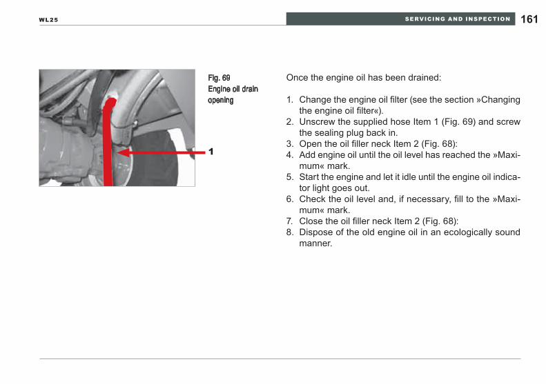
SERVICING AND INSPECTION 161WL25
Fig. 69 Engine oil drain opening
1
Once the engine oil has been drained:
Change the engine oil filter 1. (see the section »Changing the engine oil filter«).Unscrew the supplied hose Item 1 (Fig. 69) and screw 2. the sealing plug back in.Open the oil filler neck Item 2 (Fig. 68):3. Add engine oil until the oil level has reached the »Maxi-4. mum« mark.Start the engine and let it idle until the engine oil indica-5. tor light goes out.Check the oil level and, if necessary, fill to the »Maxi-6. mum« mark.Close the oil filler neck Item 2 (Fig. 68):7. Dispose of the old engine oil in an ecologically sound 8. manner.
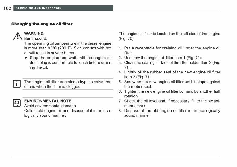
SERVICING AND INSPECTION162
Changing the engine oil filter
The engine oil filter is located on the left side of the engine (Fig. 70).
Put a receptacle for draining oil under the engine oil 1. filter. Unscrew the engine oil filter item 1 (Fig. 71):2. Clean the sealing surface of the filter holder Item 2 (Fig. 3. 71).Lightly oil the rubber seal of the new engine oil filter 4. item 3 (Fig. 71).Screw on the new engine oil filter until it stops against 5. the rubber seal.Tighten the new engine oil filter by hand by another half 6. rotation.Check the oil level and, if necessary, fill to the »Maxi-7. mum« mark.Dispose of the old engine oil filter in an ecologically 8. sound manner.
WARNINGBurn hazard.The operating oil temperature in the diesel engine is more than 93°C (200°F). Skin contact with hot oil will result in severe burns.
Stop the engine and wait until the engine oil ►drain plug is comfortable to touch before drain-ing the oil.
eNVIRONmeNTAl NOTeAvoid environmental damage.Collect old engine oil and dispose of it in an eco-logically sound manner.
The engine oil filter contains a bypass valve that opens when the filter is clogged.
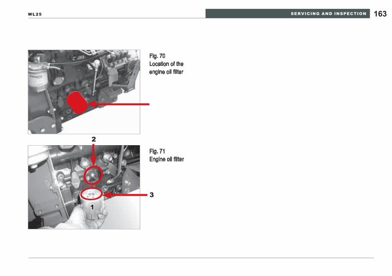
SERVICING AND INSPECTION 163WL25
Fig. 70 Location of the engine oil filter
Fig. 71 Engine oil filter
2
3
1
SERVICING AND INSPECTION164
Servicing the fuel system10.7.3
The fuel passes from the tank through a pre-filter and a sieve with water separator and is then conveyed by an electric feed pump through the main filter to the fuel injec-tion pump.
The filters and the feed pump are located in the engine compartment. To access them, open the engine enclosure and tilt the operator’s platform.
WARNINGPersonal injury hazard.Moving engine components can crush or cut. Hot engine components can cause serious burns.
Do not open the engine enclosure until the en- ►gine stops.Do not touch engine components until they have ►cooled.
Fire/explosion hazard.Fuel and fumes can explode or catch fire.
Do not smoke or change the fuel filter near an ►open flame.Do not mix gasoline with diesel fuel. ►
eNVIRONmeNTAl NOTeAvoid environmental damage.Collect leaking fuel and dispose of it in an ecologi-cally sound manner.
Service the fuel system according to the inspection intervals specified in this operator’s manual.Use only clean, high-grade diesel fuel. Do not use gasoline.Always replace all the fuel filters at the same time.
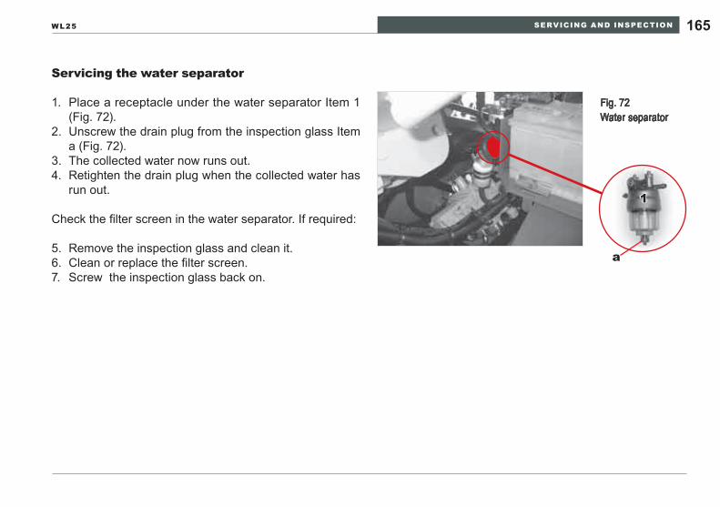
SERVICING AND INSPECTION 165WL25
Servicing the water separator
Fig. 72 Water separator
1
a
Place a receptacle under the water separator Item 1 1. (Fig. 72).Unscrew the drain plug from the inspection glass Item 2. a (Fig. 72).The collected water now runs out.3. Retighten the drain plug when the collected water has 4. run out.
Check the filter screen in the water separator. If required:
Remove the inspection glass and clean it.5. Clean or replace the filter screen.6. Screw the inspection glass back on.7.
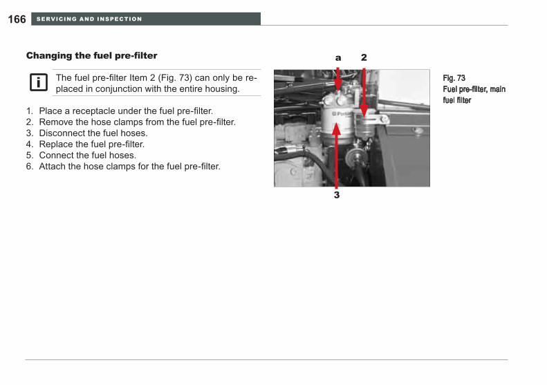
SERVICING AND INSPECTION166
Changing the fuel pre-filter
Fig. 73 Fuel pre-filter, main fuel filter
a 2
3
Place a receptacle under the fuel pre-filter.1. Remove the hose clamps from the fuel pre-filter.2. Disconnect the fuel hoses.3. Replace the fuel pre-filter.4. Connect the fuel hoses.5. Attach the hose clamps for the fuel pre-filter.6.
The fuel pre-filter Item 2 (Fig. 73) can only be re-placed in conjunction with the entire housing.
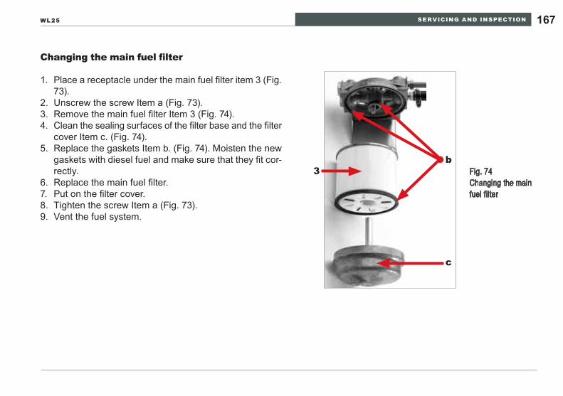
SERVICING AND INSPECTION 167WL25
Changing the main fuel filter
Fig. 74 Changing the main fuel filter
b
c
3
Place a receptacle under the main fuel filter item 3 (Fig. 1. 73).Unscrew the screw Item a (Fig. 73).2. Remove the main fuel filter Item 3 (Fig. 74).3. Clean the sealing surfaces of the filter base and the filter 4. cover Item c. (Fig. 74).Replace the gaskets Item b. (Fig. 74). Moisten the new 5. gaskets with diesel fuel and make sure that they fit cor-rectly.Replace the main fuel filter.6. Put on the filter cover.7. Tighten the screw Item a (Fig. 73).8. Vent the fuel system.9.
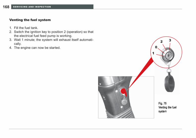
SERVICING AND INSPECTION168
Venting the fuel system
Fill the fuel tank.1. Switch the ignition key to position 2 (operation) so that 2. the electrical fuel feed pump is working.Wait 1 minute; the system will exhaust itself automati-3. cally.The engine can now be started.4.
Fig. 75 Venting the fuel system
1
2 3
0
SERVICING AND INSPECTION 169WL25
Servicing the air filter system10.7.4
The loader is equipped with a dry air filter for filtering the engine intake air. The dry air filter consists of a main filter and a safety filter element. To access the dry air filter, open the engine enclosure.
WARNINGCrushing/shearing hazard.Moving engine parts can crush and cut.
Do not open the engine enclosure unless the ►engine is stopped to avoid hazards from moving objects (cooling fan and drive belts for the fan and alternator).
Burn hazard.Engine components can get very hot during op-eration.
Do not touch the engine mass, exhaust system, ►or cooling system immediately after stopping the engine.Wait until the stopped engine has cooled to the ►point that the exhaust system, engine mass and cooling system are comfortable to touch
Service the air filter according to the inspection intervals specified in this operator’s manual.Dirty, contaminated air entering the engine will cause damage and reduce performance.Never let the engine run if parts of the air intake system are removed.Replace damaged air filters immediately.
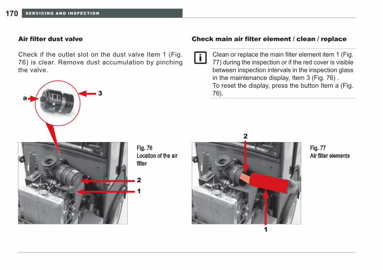
SERVICING AND INSPECTION170
Air filter dust valve
Check if the outlet slot on the dust valve Item 1 (Fig. 76) is clear. Remove dust accumulation by pinching the valve.
Check main air filter element / clean / replace
Clean or replace the main filter element item 1 (Fig. 77) during the inspection or if the red cover is visible between inspection intervals in the inspection glass in the maintenance display, Item 3 (Fig. 76) .To reset the display, press the button Item a (Fig. 76).
Fig. 76 Location of the air filter
3
12
a
Fig. 77 Air filter elements
1
2
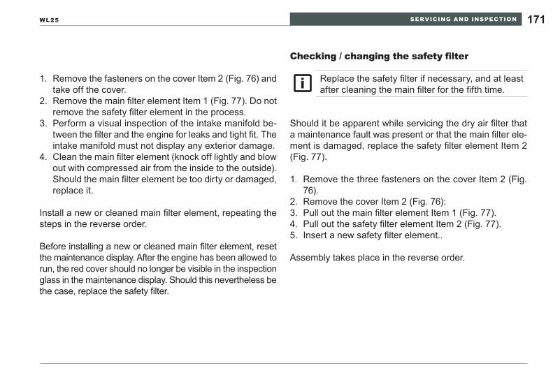
SERVICING AND INSPECTION 171WL25
Install a new or cleaned main filter element, repeating the steps in the reverse order.
Before installing a new or cleaned main filter element, reset the maintenance display. After the engine has been allowed to run, the red cover should no longer be visible in the inspection glass in the maintenance display. Should this nevertheless be the case, replace the safety filter.
Checking / changing the safety filter
Should it be apparent while servicing the dry air filter that a maintenance fault was present or that the main filter ele-ment is damaged, replace the safety filter element Item 2 (Fig. 77).
Remove the fasteners on the cover Item 2 (Fig. 76) and 1. take off the cover.Remove the main filter element Item 1 (Fig. 77). Do not 2. remove the safety filter element in the process.Perform a visual inspection of the intake manifold be-3. tween the filter and the engine for leaks and tight fit. The intake manifold must not display any exterior damage.Clean the main filter element (knock off lightly and blow 4. out with compressed air from the inside to the outside). Should the main filter element be too dirty or damaged, replace it.
Remove the three fasteners on the cover Item 2 (Fig. 1. 76).Remove the cover Item 2 (Fig. 76):2. Pull out the main filter element Item 1 (Fig. 77).3. Pull out the safety filter element Item 2 (Fig. 77).4. Insert a new safety filter element..5.
Assembly takes place in the reverse order.
Replace the safety filter if necessary, and at least after cleaning the main filter for the fifth time.
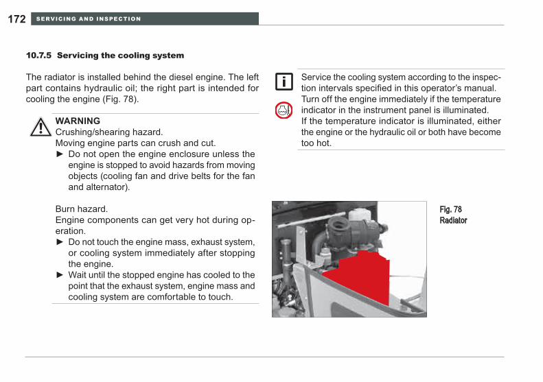
SERVICING AND INSPECTION172
Servicing the cooling system10.7.5
The radiator is installed behind the diesel engine. The left part contains hydraulic oil; the right part is intended for cooling the engine (Fig. 78).
Fig. 78 Radiator
WARNINGCrushing/shearing hazard.Moving engine parts can crush and cut.
Do not open the engine enclosure unless the ►engine is stopped to avoid hazards from moving objects (cooling fan and drive belts for the fan and alternator).
Burn hazard.Engine components can get very hot during op-eration.
Do not touch the engine mass, exhaust system, ►or cooling system immediately after stopping the engine.Wait until the stopped engine has cooled to the ►point that the exhaust system, engine mass and cooling system are comfortable to touch.
Service the cooling system according to the inspec-tion intervals specified in this operator’s manual.Turn off the engine immediately if the temperature indicator in the instrument panel is illuminated.If the temperature indicator is illuminated, either the engine or the hydraulic oil or both have become too hot.
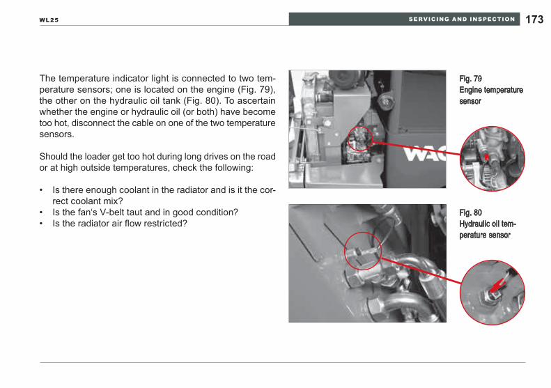
SERVICING AND INSPECTION 173WL25
The temperature indicator light is connected to two tem-perature sensors; one is located on the engine (Fig. 79), the other on the hydraulic oil tank (Fig. 80). To ascertain whether the engine or hydraulic oil (or both) have become too hot, disconnect the cable on one of the two temperature sensors.
Should the loader get too hot during long drives on the road or at high outside temperatures, check the following:
Is there enough coolant in the radiator and is it the cor-• rect coolant mix?Is the fan‘s V-belt taut and in good condition?• Is the radiator air flow restricted?•
Fig. 80 Hydraulic oil tem-perature sensor
Fig. 79 Engine temperature sensor
SERVICING AND INSPECTION174
Checking the coolant level / refilling the coolant
WARNINGBurn hazard.Hot fluid (exceeding 93°C (200°F)) will spray un-der pressure. Contact with skin will cause severe burns.
Do not remove the radiator cap if the engine is ►at operating temperature.
Poison hazard.Coolant can be harmful or fatal if swallowed.
If hot coolant makes contact with the skin or ►eyes, rinse immediately with clear water and seek immediate medical attention.If coolant is swallowed, seek immediate medi- ►cal attention.
eNVIRONmeNTAl NOTeAvoid environmental damage.Do not allow antifreeze and coolant to be released uncontrollably into the environment.Collect antifreeze and coolant and dispose of it in an ecologically sound manner.
The coolant must consist of equal parts of water and antifreeze. This mix guarantees an optimal ratio of cooling performance and corrosion protection.Do not pour in the coolant too quickly if the full amount is to be poured in, e.g. when changing the coolant.Do not exceed a refill rate of 5 l/min (1.3 gpm) to reduce the potential for air entrapment during fill-ing. Use the capacity guide on page 151. Fill until the coolant is below the neck of the radiator cap spout. Replace the cap and run the engine briefly.Stop the engine and check the level. Add coolant if the level has dropped.
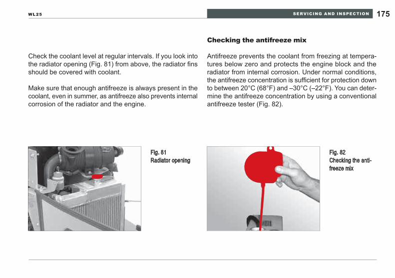
SERVICING AND INSPECTION 175WL25
Check the coolant level at regular intervals. If you look into the radiator opening (Fig. 81) from above, the radiator fins should be covered with coolant.
Make sure that enough antifreeze is always present in the coolant, even in summer, as antifreeze also prevents internal corrosion of the radiator and the engine.
Checking the antifreeze mix
Antifreeze prevents the coolant from freezing at tempera-tures below zero and protects the engine block and the radiator from internal corrosion. Under normal conditions, the antifreeze concentration is sufficient for protection down to between 20°C (68°F) and –30°C (–22°F). You can deter-mine the antifreeze concentration by using a conventional antifreeze tester (Fig. 82).
Fig. 81 Radiator opening
Fig. 82 Checking the anti-freeze mix
SERVICING AND INSPECTION176
After the coolant has drained completely, flush the system with clear water and making certain to capture the drained liquid in a container.
Changing the coolant
Stop the loader on a horizontal surface and set the park-1. ing brake.Lower the loader lift arms and attachment to the ground 2. or the work surface..Stop the engine.3. Refer to 4. Section 10, page 151 for the volume of coolant and select a drain container of sufficient capacity to avoid spillage.Remove the radiator cap.5. Remove the lower radiator hose (remove the hose clamp 6. and remove the hose).
Correctly reattach the lower radiator hose.1. Mix new coolant using equal parts of clean tap water 2. and new antifreeze.Pour the new coolant into the radiator opening until the 3. radiator fins are covered with coolant. Do not add the new coolant at a rate faster than 5 l/min (1.3 gpm) to reduce the risk of air pockets in the cooling system.Install the radiator cap.4. Check the coolant level once again after half an hour 5. of operation.
NOTICEReplace the coolant after two years of use.The coolant must consist of equal parts of water and antifreeze. This mix guarantees an optimal ratio of cooling performance and corrosion protection.Do not exceed a refill rate of 5 l/min (1.3 gpm) to re-duce the potential for air entrapment during filling.Use the capacity guide on page 151. Fill until the coolant is below the neck of the radiator cap spout. Replace the cap and run the engine briefly.Stop the engine and check the level. Add coolant if the level has dropped.
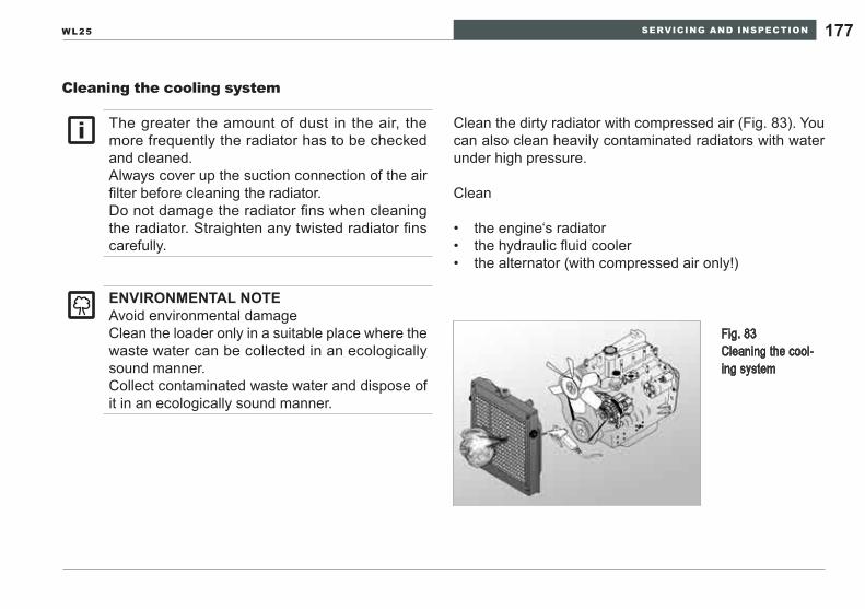
SERVICING AND INSPECTION 177WL25
Cleaning the cooling system
Clean the dirty radiator with compressed air (Fig. 83). You can also clean heavily contaminated radiators with water under high pressure.
Clean
the engine‘s radiator• the hydraulic fluid cooler• the alternator (with compressed air only!)•
Fig. 83 Cleaning the cool-ing system
eNVIRONmeNTAl NOTeAvoid environmental damageClean the loader only in a suitable place where the waste water can be collected in an ecologically sound manner.Collect contaminated waste water and dispose of it in an ecologically sound manner.
The greater the amount of dust in the air, the more frequently the radiator has to be checked and cleaned.Always cover up the suction connection of the air filter before cleaning the radiator.Do not damage the radiator fins when cleaning the radiator. Straighten any twisted radiator fins carefully.
SERVICING AND INSPECTION178
Servicing the hydraulic system10.7.6
WARNINGCrushing/shearing hazard.Moving engine parts can crush and cut.
Do not open the engine enclosure unless the ►engine is stopped to avoid hazards from moving objects (cooling fan and drive belts for the fan and alternator).
Burn hazard.The operating temperature of the hydraulic sys-tem is 93°C (200°F). Contact with skin will cause severe burns.
Rinse with water immediately and seek medical ►treatment.
Injury hazard.High pressure hydraulic streams can penetrate skin, resulting in infections.
If oil penetrates the skin, seek medical treatment ►immediately. If hydraulic fluid enters an eye, seek medical ►attention immediately.Use a piece of cardboard or heavy paper to ►search for hydraulic system leaks
Service the hydraulic system according to the inspection intervals specified in this operator’s manual.Exercise extreme cleanliness when carrying out service work on the hydraulic system. Impurities in the hydraulic fluid in the form of dirt or water can result in premature wear or failure of the entire system.
Open hydraulic systems only if they have been relieved of pressure. Even if a loader is parked on a horizontal sur-face with its loader lift arms completely lowered and engine turned off, there can still be considerable residual pressure in parts of the hydraulic system. Residual pressure reduces gradually at first. Should a hydraulic system be opened immediately after shutting down, the system has to be de-pressurized as described in Section 8, page 122 »Relieving residual pressure in the hydraulic system«.
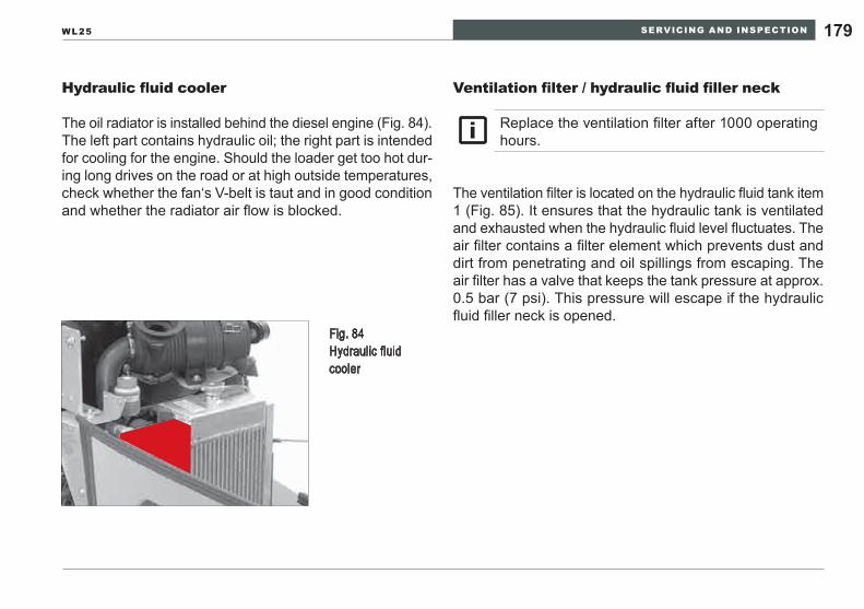
SERVICING AND INSPECTION 179WL25
Hydraulic fluid cooler
The oil radiator is installed behind the diesel engine (Fig. 84). The left part contains hydraulic oil; the right part is intended for cooling for the engine. Should the loader get too hot dur-ing long drives on the road or at high outside temperatures, check whether the fan‘s V-belt is taut and in good condition and whether the radiator air flow is blocked.
Ventilation filter / hydraulic fluid filler neck
The ventilation filter is located on the hydraulic fluid tank item 1 (Fig. 85). It ensures that the hydraulic tank is ventilated and exhausted when the hydraulic fluid level fluctuates. The air filter contains a filter element which prevents dust and dirt from penetrating and oil spillings from escaping. The air filter has a valve that keeps the tank pressure at approx. 0.5 bar (7 psi). This pressure will escape if the hydraulic fluid filler neck is opened.
Replace the ventilation filter after 1000 operating hours.
Fig. 84 Hydraulic fluid cooler
SERVICING AND INSPECTION180
Checking the hydraulic fluid level
The hydraulic oil tank is located on the left side of the rear frame. To access it, open the engine enclosure (reference Section 10.7.1, pages 154-157).
Stop the loader on a horizontal surface and set the park-1. ing brake.Lower the loader lift arms and attachment to the ground 2. or work surface.Stop the engine.3. Remove the hydraulic oil filler neck Item 1 (Fig. 85) 4. slightly so that the pressure can escape from the tank before removing the cap completely.The dip stick is located on the underside of the air filter. 5. Remove the dip stick (Fig. 86).Wipe the dip stick with a clean, lint-free cleaning rag.6. Put the dip stick back in.7. Pull the dip stick out again.8. Check the oil level. The oil level must be between the 9. »minimum« and »maximum« marks.Put the dip stick back in after checking the oil level.10. Close the hydraulic fluid filler neck item 1 (Fig. 85).11.
Never let the oil level drop below the »Minimum« mark on the dip stick.When adding oil, never let the »Maximum« mark on the dip stick be exceeded.Oil cloudiness means that water or air is in the system, which could damage the hydraulic pump. Contact trained specialized personnel to eliminate the fault. Do not drive the loader until the fault has been eliminated.
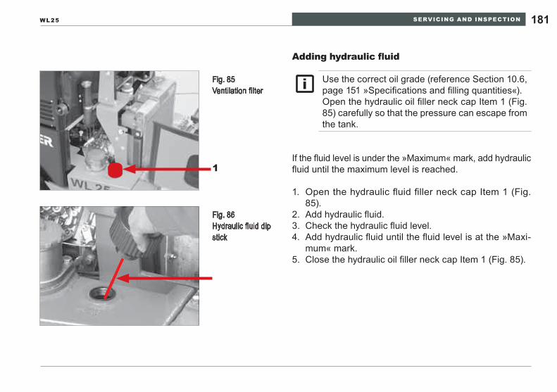
SERVICING AND INSPECTION 181WL25
Adding hydraulic fluid
If the fluid level is under the »Maximum« mark, add hydraulic fluid until the maximum level is reached.
Open the hydraulic fluid filler neck cap Item 1 (Fig. 1. 85).Add hydraulic fluid.2. Check the hydraulic fluid level.3. Add hydraulic fluid until the fluid level is at the »Maxi-4. mum« mark.Close the hydraulic oil filler neck cap Item 1 (Fig. 85).5.
Use the correct oil grade (reference Section 10.6, page 151 »Specifications and filling quantities«).Open the hydraulic oil filler neck cap Item 1 (Fig. 85) carefully so that the pressure can escape from the tank.
1
Fig. 85 Ventilation filter
Fig. 86 Hydraulic fluid dip stick
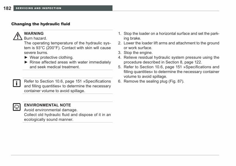
SERVICING AND INSPECTION182
Changing the hydraulic fluid
Stop the loader on a horizontal surface and set the park-1. ing brake.Lower the loader lift arms and attachment to the ground 2. or work surface.Stop the engine.3. Relieve residual hydraulic system pressure using the 4. procedure described in Section 8, page 122.Refer to 5. Section 10.6, page 151 »Specifications and filling quantities« to determine the necessary container volume to avoid spillage.Remove the sealing plug (Fig. 87).6.
WARNINGBurn hazard.The operating temperature of the hydraulic sys-tem is 93°C (200°F). Contact with skin will cause severe burns.
Wear protective clothing. ►Rinse affected areas with water immediately ►and seek medical treatment.
eNVIRONmeNTAl NOTeAvoid environmental damage.Collect old hydraulic fluid and dispose of it in an ecologically sound manner.
Refer to Section 10.6, page 151 »Specifications and filling quantities« to determine the necessary container volume to avoid spillage.
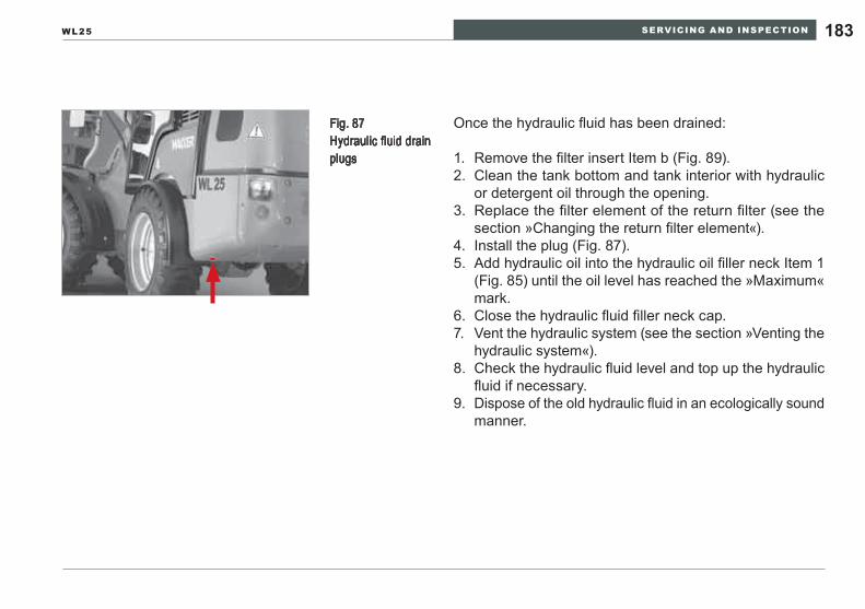
SERVICING AND INSPECTION 183WL25
Once the hydraulic fluid has been drained:
Remove the filter insert Item b (Fig. 89).1. Clean the tank bottom and tank interior with hydraulic 2. or detergent oil through the opening.Replace the filter element of the return filter (see the 3. section »Changing the return filter element«).Install the plug (Fig. 87).4. Add hydraulic oil into the hydraulic oil filler neck Item 1 5. (Fig. 85) until the oil level has reached the »Maximum« mark.Close the hydraulic fluid filler neck cap.6. Vent the hydraulic system (see the section »Venting the 7. hydraulic system«).Check the hydraulic fluid level and top up the hydraulic 8. fluid if necessary.Dispose of the old hydraulic fluid in an ecologically sound 9. manner.
Fig. 87 Hydraulic fluid drain plugs
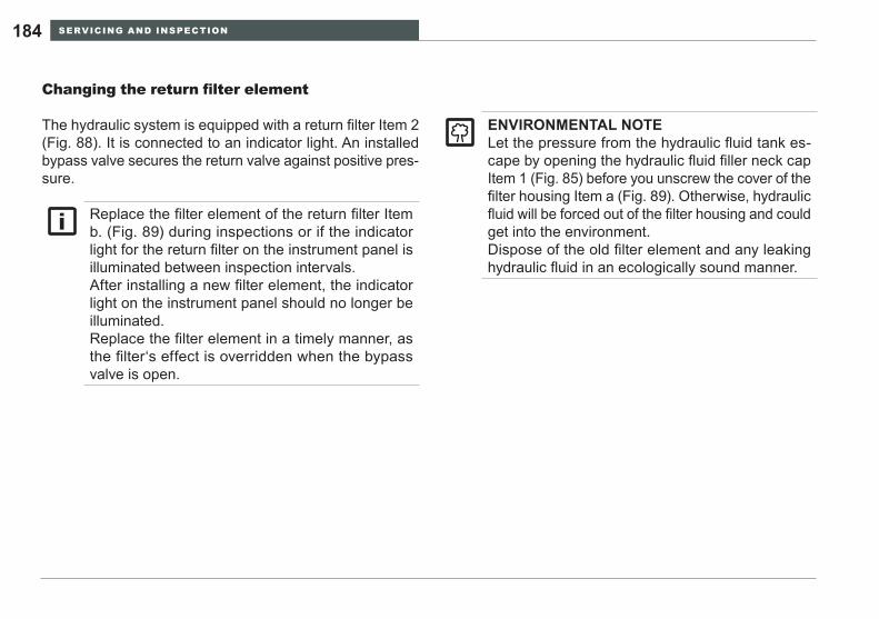
SERVICING AND INSPECTION184
Changing the return filter element
The hydraulic system is equipped with a return filter Item 2 (Fig. 88). It is connected to an indicator light. An installed bypass valve secures the return valve against positive pres-sure.
eNVIRONmeNTAl NOTeLet the pressure from the hydraulic fluid tank es-cape by opening the hydraulic fluid filler neck cap Item 1 (Fig. 85) before you unscrew the cover of the filter housing Item a (Fig. 89). Otherwise, hydraulic fluid will be forced out of the filter housing and could get into the environment.Dispose of the old filter element and any leaking hydraulic fluid in an ecologically sound manner.
Replace the filter element of the return filter Item b. (Fig. 89) during inspections or if the indicator light for the return filter on the instrument panel is illuminated between inspection intervals.After installing a new filter element, the indicator light on the instrument panel should no longer be illuminated.Replace the filter element in a timely manner, as the filter‘s effect is overridden when the bypass valve is open.
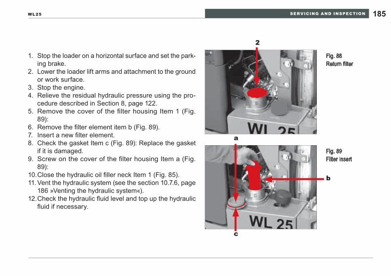
SERVICING AND INSPECTION 185WL25
Stop the loader on a horizontal surface and set the park-1. ing brake.Lower the loader lift arms and attachment to the ground 2. or work surface.Stop the engine.3. Relieve the residual hydraulic pressure using the pro-4. cedure described in Section 8, page 122.Remove the cover of the filter housing Item 1 (Fig. 5. 89):Remove the filter element item b (Fig. 89).6. Insert a new filter element.7. Check the gasket Item c (Fig. 89): Replace the gasket 8. if it is damaged.Screw on the cover of the filter housing Item a (Fig. 9. 89):Close the hydraulic oil filler neck Item 1 (Fig. 85).10. Vent the hydraulic system 11. (see the section 10.7.6, page 186 »Venting the hydraulic system«).Check the hydraulic fluid level and top up the hydraulic 12. fluid if necessary.
Fig. 88 Return filter
2
Fig. 89 Filter insert
b
a
c
SERVICING AND INSPECTION186
Venting the hydraulic system
Check the fluid level in the hydraulic fluid tank. If nec-1. essary, add hydraulic fluid until the fluid level is at the »Maximum« mark.Start the engine and let it idle for a few minutes.2. Drive the piston rod for all the hydraulic cylinders in and 3. out several times.With the engine running, turn the steering wheel to 4. its maximum angle of turn in both directions until the steering can be actuated faultlessly and without any noises.Check the oil level in the hydraulic fluid tank after ex-5. hausting has been completed. If necessary, add hydrau-lic fluid until the fluid level is at the »Maximum« mark.
Servicing the axles10.7.7
The axial piston oil motor of the loader‘s drive hydraulics is mounted on the transfer case. The transfer case is con-nected to the rear axle of the loader. The front axle is pow-ered via the drive shaft.
WARNINGPossibility of injury or equipment damage.Trapped air in the hydraulic system will cause erratic or inadvertent movement of the loader arms.
Before returning the loader to work after servic- ►ing, it is necessary to purge any air trapped in the hydraulic system.
Service the transmission and the axles according to the inspection intervals specified in this opera-tor’s manual.Checking / filling and draining screws can be found in the same place on the front and rear axles.
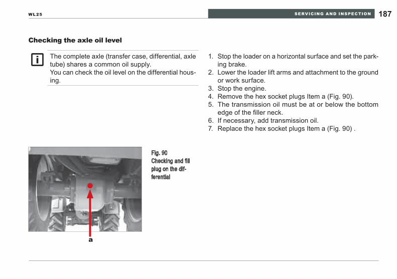
SERVICING AND INSPECTION 187WL25
Checking the axle oil level
Fig. 90 Checking and fill plug on the dif-ferential
a
Stop the loader on a horizontal surface and set the park-1. ing brake.Lower the loader lift arms and attachment to the ground 2. or work surface.Stop the engine.3. Remove the hex socket plugs Item a (Fig. 90).4. The transmission oil must be at or below the bottom 5. edge of the filler neck.If necessary, add transmission oil.6. Replace the hex socket plugs Item a (Fig. 90) .7.
The complete axle (transfer case, differential, axle tube) shares a common oil supply.You can check the oil level on the differential hous-ing.
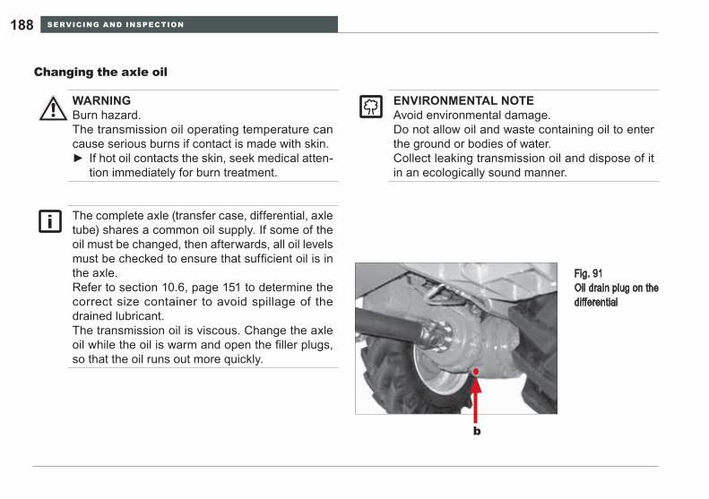
SERVICING AND INSPECTION188
Fig. 91 Oil drain plug on the differential
b
Changing the axle oil
WARNINGBurn hazard.The transmission oil operating temperature can cause serious burns if contact is made with skin.
If hot oil contacts the skin, seek medical atten- ►tion immediately for burn treatment.
eNVIRONmeNTAl NOTeAvoid environmental damage.Do not allow oil and waste containing oil to enter the ground or bodies of water.Collect leaking transmission oil and dispose of it in an ecologically sound manner.
The complete axle (transfer case, differential, axle tube) shares a common oil supply. If some of the oil must be changed, then afterwards, all oil levels must be checked to ensure that sufficient oil is in the axle.Refer to section 10.6, page 151 to determine the correct size container to avoid spillage of the drained lubricant.The transmission oil is viscous. Change the axle oil while the oil is warm and open the filler plugs, so that the oil runs out more quickly.
SERVICING AND INSPECTION 189WL25
Once the transmission oil has been drained:Stop the loader on a horizontal surface and set the park-1. ing brake.Lower the loader lift arms and attachment to the ground 2. or work surface.Stop the engine.3. Place a sufficiently large receptacle under the drain 4. opening of the differential housing item b (Fig. 91).Remove the hex socket plug Item a (Fig. 90); the trans-5. mission oil will now drain more quickly.Remove the hex socket plug Item b (Fig. 91).6. The transmission oil drains off.7.
Replace the hex socket plug Item b (Fig. 91) on the dif-1. ferential housing.Add new transmission oil through the filler neck into the 2. axle Item a (Fig. 90).The transmission oil must be at or below the bottom 3. edge of the filler neck.Replace the hex socket plug Item a (Fig. 90) on the dif-4. ferential housing.Check the axle oil level once again after half an hour of 5. operation and add in transmission oil if necessary.
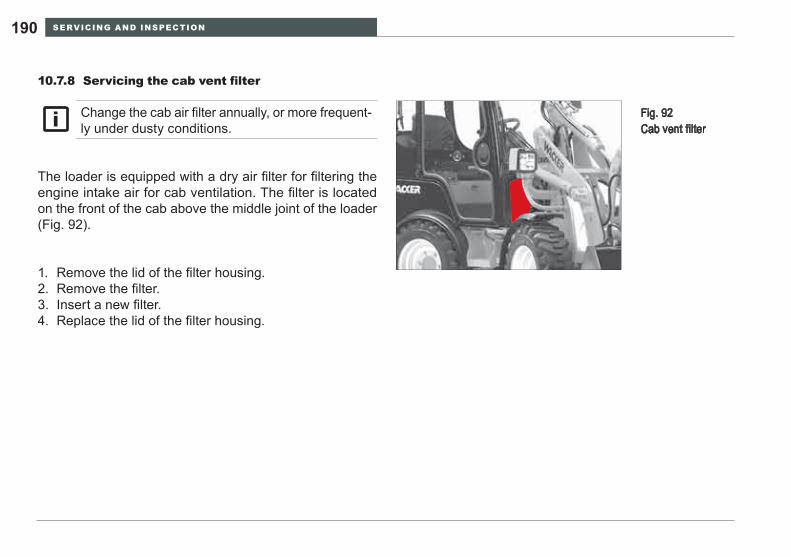
SERVICING AND INSPECTION190
Servicing the cab vent filter10.7.8
The loader is equipped with a dry air filter for filtering the engine intake air for cab ventilation. The filter is located on the front of the cab above the middle joint of the loader (Fig. 92).
Change the cab air filter annually, or more frequent-ly under dusty conditions.
Fig. 92 Cab vent filter
Remove the lid of the filter housing.1. Remove the filter.2. Insert a new filter.3. Replace the lid of the filter housing.4.
SERVICING AND INSPECTION 191WL25
Servicing the brakes10.7.9
The hydrostatic drive is used as an operating brake and operates equally without wear resistance on all four wheels. In addition, the loader has a foot brake and parking brake. The foot brake and parking brake consists of a hub brake on the differential. The parking brake is actuated via a bowden cable, by means of the handbrake lever. The foot brake is activated hydraulically via brake lines and main brake cylinders by means of the braking-inching pedal.
WARNINGPersonal injury hazard.The service and parking brakes are essential for safe operation of the wheel loader. Loss of control is hazardous to the operator as well as other people on the work site or public roads.
Always check brake performance at the start ►of each work shift and stay alert to changes in response or capacity. A loss in response or capacity must be corrected. Stop the wheel loader in a safe place and low- ►er the loader lift arms and attachment to the ground.Stop the engine and notify the supervisor or a ►technician to diagnose the brake system and make any needed repairs before resuming work.
SERVICING AND INSPECTION192
Checking the brake fluid level / adding brake fluid
The brake fluid reservoir is on the left at the back, under-neath the engine enclosure (Fig. 93). The control marks »MAx« and »MIN« are on the side of the container.
If the brake oil level in the brake fluid container falls below the »MIN« mark, fill with prescribed brake fluid up to the »MAx« mark and have the brake system checked by a trained specialist.
WARNINGHealth hazard.Brake fluid can be absorbed into the skin or cause infections.
Avoid contact with skin and eyes. ►Wear protective gloves and eye protection. ►
eNVIRONmeNTAl NOTeAvoid environmental damage.Do not allow oil and waste containing oil to spill on the ground or get into bodies of water.Collect leaking transmission oil and dispose of it in an ecologically sound manner.
Using the wrong brake fluid damages the brake system.Only use brake fluid approved by Wacker Neuson for the braking system (see section 10.6, page 151 »Specifications and fill quantities«).If you are frequently adding brake fluid between inspections, then there is a system leak. Do not work with the loader again until the faults have been eliminated.
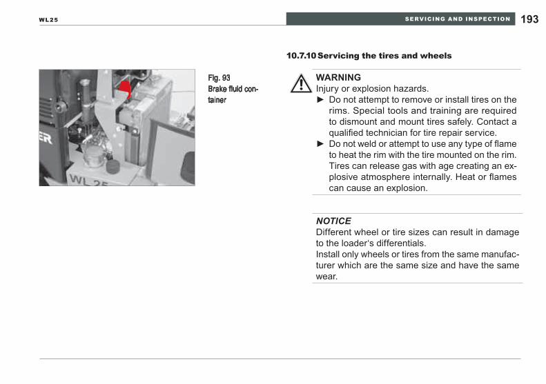
SERVICING AND INSPECTION 193WL25
Fig. 93 Brake fluid con-tainer
Servicing the tires and wheels10.7.10
WARNINGInjury or explosion hazards.
Do not attempt to remove or install tires on the ►rims. Special tools and training are required to dismount and mount tires safely. Contact a qualified technician for tire repair service.Do not weld or attempt to use any type of flame ►to heat the rim with the tire mounted on the rim. Tires can release gas with age creating an ex-plosive atmosphere internally. Heat or flames can cause an explosion.
NOTICEDifferent wheel or tire sizes can result in damage to the loader‘s differentials.Install only wheels or tires from the same manufac-turer which are the same size and have the same wear.
SERVICING AND INSPECTION194
Inflating the tires
Stop the loader on a horizontal surface and set the park-1. ing brake.Lower the loader lift arms and attachment to the ground 2. or work surface.Stop the engine.3. Remove the valve stem cap on the tire valve.4. Place the pneumatic chuck of the filling device on the 5. tire valve so that it stays in place.Inflate the tires to the specified pressure.6. Remove the pneumatic chuck of the filling device from 7. the tire valve.Replace the valve stem cap back on the tire valve.8.
WARNINGExplosion hazard.Overinflating tires can cause them to explode.
Use only filling devices with a calibrated pres- ►sure gauge to pump up tires.Make sure that no one is in the danger area ►when you pump up tires.
These instructions refer to inflating in the event of loss of air pressure. Observe the air pressure specified for the loader‘s tire size (see air pressure table for tires).In the case of complete air pressure loss, this work may only be performed by trained, experienced spe-cialized personnel with appropriate equipment.
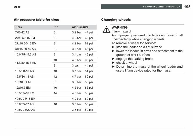
SERVICING AND INSPECTION 195WL25
Air pressure table for tires
Tires PR Air pressure7.00-12 AS 6 3,2 bar 47 psi
27x8.50-15 EM 8 4,2 bar 62 psi
27x10.50-15 EM 8 4,2 bar 62 psi
31x15.50-15 AS 8 3,1 bar 45 psi
10.0/75-15,3 AS 8 3,1 bar 45 psi
11.5/80-15,3 AS10 4,5 bar 66 psi
8 3 bar 44 psi
10.5/80-18 AS 10 3,7 bar 54 psi
12.5/80-18 AS 12 4,7 bar 69 psi
10x16.5 EM 8 3,6 bar 53 psi
12x16,5 EM 10 4,5 bar 66 psi
15.5/55-18 EM 14 4,0 bar 60 psi
405/70 R18 EM 4,0 bar 60 psi
15.0/55-17 AS 10 3,5 bar 50 psi
405/70 R20 AS 3,5 bar 50 psi
Changing wheels
WARNINGInjury hazard.An improperly secured machine can move or fall unexpectedly while changing wheels.To remove a wheel for service:
stop the loader on a flat surface ►lower the loader lift arms and attachment to the ►ground or work surfaceengage the parking brake ►chock a wheel ►Determine the mass of the wheel loader and ►use a lifting device rated for the mass.
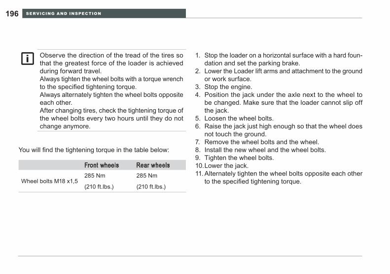
SERVICING AND INSPECTION196
You will find the tightening torque in the table below:
Front wheels Rear wheels
Wheel bolts M18 x1,5285 Nm 285 Nm
(210 ft.lbs.) (210 ft.lbs.)
Stop the loader on a horizontal surface with a hard foun-1. dation and set the parking brake.Lower the Loader lift arms and attachment to the ground 2. or work surface.Stop the engine.3. Position the jack under the axle next to the wheel to 4. be changed. Make sure that the loader cannot slip off the jack.Loosen the wheel bolts.5. Raise the jack just high enough so that the wheel does 6. not touch the ground.Remove the wheel bolts and the wheel.7. Install the new wheel and the wheel bolts.8. Tighten the wheel bolts.9. Lower the jack.10. Alternately tighten the wheel bolts opposite each other 11. to the specified tightening torque.
Observe the direction of the tread of the tires so that the greatest force of the loader is achieved during forward travel.Always tighten the wheel bolts with a torque wrench to the specified tightening torque.Always alternately tighten the wheel bolts opposite each other.After changing tires, check the tightening torque of the wheel bolts every two hours until they do not change anymore.
SERVICING AND INSPECTION 197WL25
Servicing the electrical system10.7.11
WARNINGElectric shock hazard.
Always disconnect the battery before working ►on the electrical system if tools, spare parts, etc. with electrical components or contacts could touch it.
Electric shock and burn hazards.Do not clean sensitive electrical components ►(instrument panel, dynamo, compact plug, multi-function lever, etc.) with a high-pressure cleaner.Do not touch incandescent lamps and headlight ►reflectors with your fingers if the bulbs have been illuminated.
Have malfunctions in the electrical system cor-rected by trained specialized personnel.
Fuse allocation
The electrical circuits of the wheel loader are fused to pre-vent damage from short circuits and malfunctions. The fuses are located in fuse box 1 (on the left side of the steering column) and in fuse box 2 (on the right hand side of the cab next to the wiper and light control switches).
NOTICE: If an electrical device fails to respond to a control movement, stop the wheel loader as if stopping at the end of a work shift and check the fuse for that circuit. If the fuse has failed, determine the cause of failure and repair the cause. Insert a new fuse of the specified rating and return to work.Do not continue work with a failed fuse. Do not install a fuse with a higher rated capacity than the failed fuse. This can result in serious dam-age to the electrical circuit.
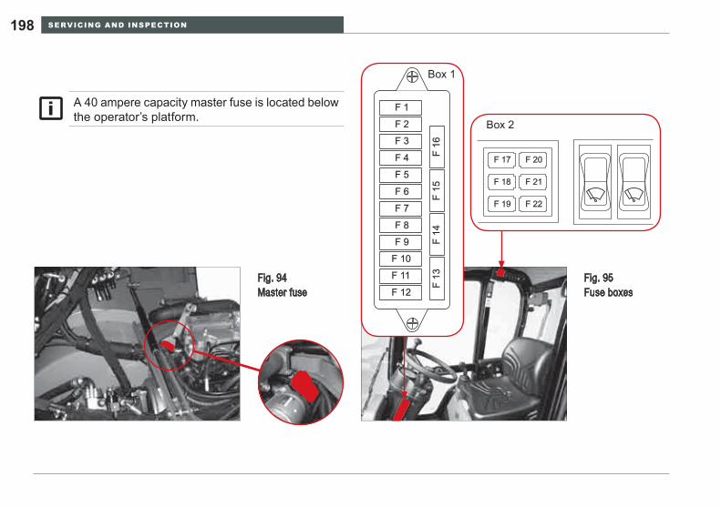
SERVICING AND INSPECTION198
A 40 ampere capacity master fuse is located below the operator’s platform.
Fig. 95 Fuse boxes
F 1
F 2
F 3
F 4
F 5
F 6
F 7
F 8
F 9
F 10
F 11
F 12
F 16
F 15
F 14
F 13
Box 1
Box 2
F 17
F 18
F 19
F 20
F 21
F 22
Fig. 94 Master fuse
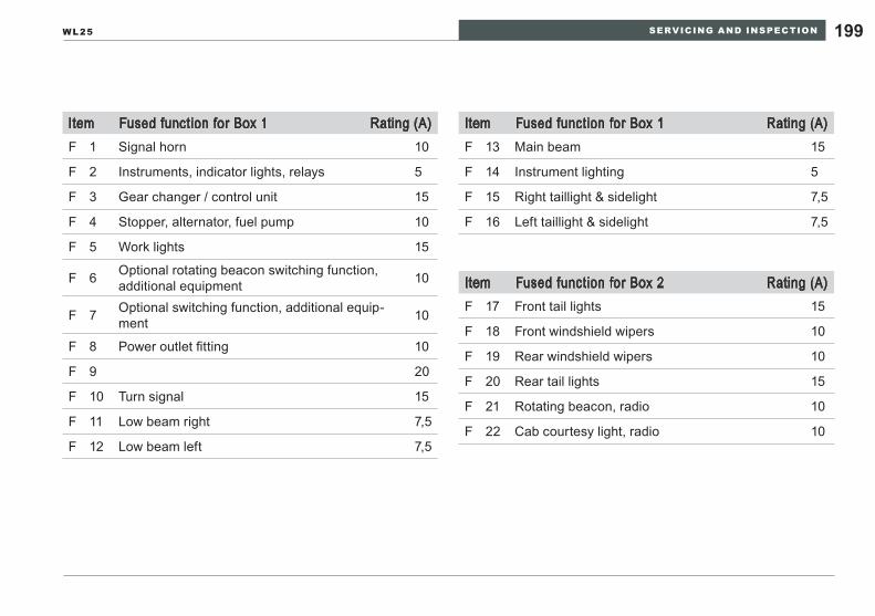
SERVICING AND INSPECTION 199WL25
Item Fused function for Box 1 Rating (A)F 1 Signal horn 10
F 2 Instruments, indicator lights, relays 5
F 3 Gear changer / control unit 15
F 4 Stopper, alternator, fuel pump 10
F 5 Work lights 15
F 6 Optional rotating beacon switching function, additional equipment 10
F 7 Optional switching function, additional equip-ment 10
F 8 Power outlet fitting 10
F 9 20
F 10 Turn signal 15
F 11 Low beam right 7,5
F 12 Low beam left 7,5
Item Fused function for Box 1 Rating (A)F 13 Main beam 15
F 14 Instrument lighting 5
F 15 Right taillight & sidelight 7,5
F 16 Left taillight & sidelight 7,5
Item Fused function for Box 2 Rating (A)F 17 Front tail lights 15
F 18 Front windshield wipers 10
F 19 Rear windshield wipers 10
F 20 Rear tail lights 15
F 21 Rotating beacon, radio 10
F 22 Cab courtesy light, radio 10

SERVICING AND INSPECTION200
Battery
The battery has a nominal voltage of 12 volts; the battery capacity is 77 Ah. The battery is located on the left side of the loader in the engine compartment Item 1 (Fig. 96). To access it, open the engine enclosure and tilt the operator cab/ platform.
WARNINGExplosion and burn hazard.Batteries produce and vent gases that can be ex-plosive if concentrated in an unventilated space.
Do not smoke or use open flames near a stor- ►age battery.Do not place objects on the battery. If a metal- ►lic object such as a wrench contacts both the positive and negative post on the battery, it will cause a direct short and a possible explosion. Severe burns can result .Cover the battery with protective insulation, or ►remove the battery entirely, if service work is to be conducted near the battery.
WARNINGBattery fluid is poisonous and corrosive.
Prevent battery fluid from coming into contact ►with your skin, eyes, mouth, or clothing.Wear protective gloves and safety goggles. ►If battery fluid contacts skin, immediately rinse ►the contaminated area with plenty of clean water and seek medical treatment.
eNVIRONmeNTAl NOTeAvoid environmental damage.Dispose of old batteries in an ecologically sound way, separate from other waste.
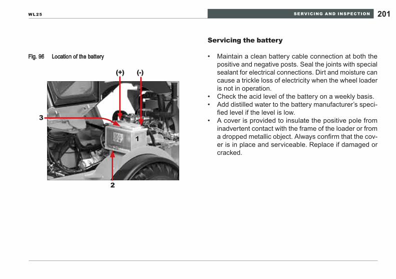
SERVICING AND INSPECTION 201WL25
Servicing the battery
Maintain a clean battery cable connection at both the • positive and negative posts. Seal the joints with special sealant for electrical connections. Dirt and moisture can cause a trickle loss of electricity when the wheel loader is not in operation.Check the acid level of the battery on a weekly basis.• Add distilled water to the battery manufacturer’s speci-• fied level if the level is low.A cover is provided to insulate the positive pole from • inadvertent contact with the frame of the loader or from a dropped metallic object. Always confirm that the cov-er is in place and serviceable. Replace if damaged or cracked.
Location of the batteryFig. 96
3
(+) (-)
2
1
SERVICING AND INSPECTION202
Checking the battery acid level
Stop the loader on a horizontal surface and set the park-1. ing brake.Lower the loader lift arms and attachment to the ground 2. or work surface.Stop the engine.3. Open the engine enclosure 4. (Ref. section 10.7.1, page 152).Tilt the operator cab/platform 5. (Ref. section 10.7.1, pages 154-157).The acid level is visible through the battery housing. 6. MIN/MAX marks have been affixed on the outside of the battery housing. The acid level must always be between these marks.If the battery solution is below the MIN mark add distilled 7. water until the level is at the MAx mark.
Adding distilled water
Open the filling cover for each battery cell (there are 6 1. for this 12 volt battery).Add distilled water through the openings up to the MAx 2. mark in each of the six battery cells.Replace each battery cell cover.3.
WARNINGPersonal injury hazards. Do not open the engine enclosure or attempt to tilt the operator cab/platform if the engine is running. Follow the instructions in Section 10.7.1, pages 152-157, for opening the hood and tilting the cab.
Check the acid level of the battery on a weekly basis.Refill the battery with distilled water only.
SERVICING AND INSPECTION 203WL25
Disconnecting and connecting the battery / changing the battery
Removing the battery:
Stop the loader on a horizontal surface and set the park-1. ing brake.Lower the loader lift arms and attachment.2. Stop the engine.3. Before disconnecting the battery, switch off all electrical 4. controls (and the battery disconnect switch) and remove the starting key.Open the engine enclosure 5. (Ref. section 10.7.1, page 152).
WARNINGPersonal injury hazards.Do not open the engine enclosure or attempt to tilt the operator cab/platform if the engine is running. Follow the instructions in Section 10.7.1, pages 152-157, for opening the engine enclosure and tilting the cab.Always follow the correct sequence when discon-necting the battery.– Disconnecting:First the negative pole and then the positive pole.– Connecting:First the positive pole and then the negative pole.
Tilt the operator cab/ platform 6. (Ref. section 10.7.1, pages 154-157).Loosen the negative battery cable clamp and remove the 7. clamp from the post. Position the cable so it is not touch-ing the machine. Wrap an insulating material around the conducting part of the cable clamp to eliminate the risk of electrical shock (Fig. 96).Remove the protective cover to gain access to the cable 8. clamp bolt. Loosen the positive battery cable clamp and remove the clamp from the post. Position the cable so it is not touching the machine. Wrap an insulating ma-terial around the conducting part of the cable clamp to eliminate the risk of electrical shock. (Fig. 96).Remove the battery support retaining bolts, item 2 (Fig. 9. 96).Remove the battery with the lifting aid incorporated in 10. the battery identified as item 3, Fig 96. If the battery does not have an integral lifting aid, use a special strap that fits over each pole and provides a means to remove the battery.
Install the battery following the steps in the reverse order.
SERVICING AND INSPECTION204
Jump-starting / emergency starting10.8
WARNINGExplosion and burn hazard.Batteries produce and vent gases that can be explosive if concentrated in an unventilated space.
Do not smoke or use open flames near a storage battery. ►Do not place objects on the battery. If a metallic object such as a wrench contacts both the positive and nega- ►tive post on the battery, it will cause a direct short and a possible explosion. Severe burns can result .Cover the battery with protective insulation, or remove the battery entirely, if service work is to be conducted ►near the battery.If a second machine or vehicle is used as the jump start battery source, ensure that the vehicles/machines ►do not touch.Do not attempt to jump start a frozen or defective battery. A short circuit or rapid increase in heat within the ►battery can cause an explosion.Do not connect two batteries in series (negative post to positive post) because the voltage output will be 24 ►volts and damage the electrical system of the wheel loader.Use only jump-starting batteries with the same voltage. ►Use serviceable jumper cables with a heavy duty 12 volt rating. ►Lay out the jumper cables so that they cannot be struck by rotating engine parts. ►
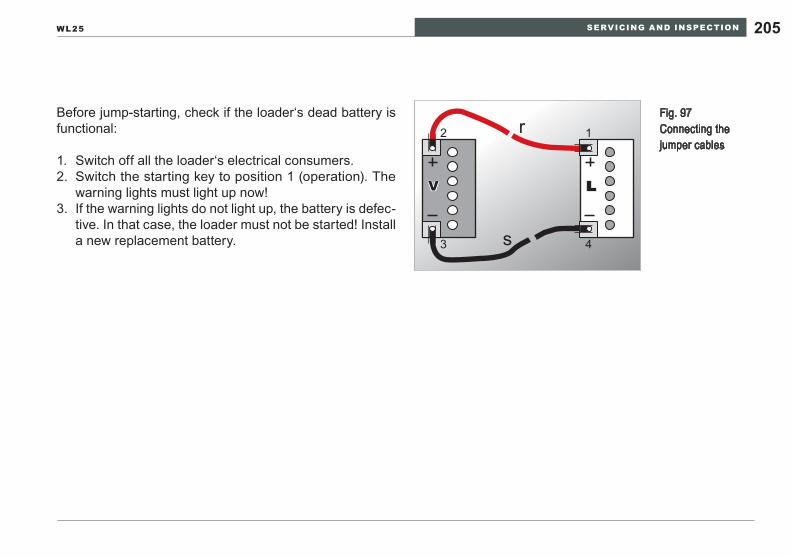
SERVICING AND INSPECTION 205WL25
Before jump-starting, check if the loader‘s dead battery is functional:
Switch off all the loader‘s electrical consumers.1. Switch the starting key to position 1 (operation). The 2. warning lights must light up now!If the warning lights do not light up, the battery is defec-3. tive. In that case, the loader must not be started! Install a new replacement battery.
Fig. 97 Connecting the jumper cables
12
3 4
r
s
V LV L
SERVICING AND INSPECTION206
Getting ready
Switch off all the loader‘s electrical controls.1. Switch the starting key to position 0.2. Drive the vehicle with the good battery (charged battery) 3. near but not touching the loader.Switch off all electrical controls on the vehicle with the 4. good battery and stop the engine.
Connect the jumper cables
Starting the engines
Start the engine of the vehicle with the good battery and 1. let it run at an increased speed.Attempt to start the loader engine.2. If the engine does not start after 15 seconds, wait one 3. minute before trying again.Once the engine has started, let both engines continue 4. to idle with the jumper cables connected for about an-other two minutes.
Detach the jumper cables(The correct sequence must be adhered to)
Connect the red jumper cable Item r (Fig. 97) to the 1. positive pole of the dead battery Item L.Connect the red jumper cable to the positive pole of the 2. charged battery Item V (Fig. 97).Connect the black jumper cable Item s to the negative 3. pole of the charged battery.Connect the black jumper cable to the negative pole of 4. the dead battery.
(As with connecting, follow the correct sequence):
Disconnect the black jumper cable first from the nega-1. tive pole of the dead battery and then from the negative pole of the charged battery.Disconnect the red jumper cable first from the positive 2. pole of the charged battery and then from the positive pole of the dead battery.
SERVICING AND INSPECTION 207WL25
Loader storage10.9
The specified measures refer to shutting down and re-start-ing the loader over longer periods of time.
Follow the operator’s manual for the engine.
Shutting down the loader
Park the loader as described in 1. section 9, page 125 »Securing the loader«.Engage the articulated frame lock 2. (Ref. Section 6.2, page 114).Raise the loader so that the tires no longer touch the 3. ground.Release the parking brake.4. Lower the loader lift arms and attachment to the 5. ground.Relieve residual hydraulic pressure, ref. 6. Section 8, page 122 »Relieving residual pressure in the hydraulic sys-tem«. Move all hydraulic controls to the neutral posi-tion.Spray bare metal parts of the loader (e.g.: the piston 7. rods of the hydraulic cylinders if they are not retracted) with an anti-corrosion agent.Preserve the engine.8.
Note: Before beginning the shutdown procedures, drive the Wheel Loader to its storage location

SERVICING AND INSPECTION208
Preserving the engine
Clean the engine in a suitable place using a high-pres-1. sure cleaner.Bring the engine to operating temperature.2. Drain the engine oil and dispose of it in an ecologically 3. sound manner.Pour anti-corrosion oil into the engine.4. Drain the fuel from the tank.5. Produce a mixture of 90% fuel and 10% anti-corrosion 6. oil and pour it into the fuel tank.Let the engine idle for 10 minutes before turning it off.7. To preserve the cylinders and combustion chamber, 8. crank the engine by hand several times.Remove the fan belt and pack it for storage so that it is 9. airtight and light-proof.Spray the belt pulley contact surface with anti-corrosion 10. agent.Close the intake and exhaust opening of the engine.11.
Storing the battery:
Remove the battery.1. Clean the battery.2. Charge the battery.3. Store the battery in a dry, well-ventilated room at ap-4. prox. 20°C (68°F).Check the acid level once a month.5. Recharge the battery before installing it again.6.
SERVICING AND INSPECTION 209WL25
Remove preservatives from the engine
Remove the closures from the intake and exhaust open-1. ing of the engine.Remove the anti-corrosion agent from the pulley.2. Install the fan belt.3. Drain the preservative oil and pour in engine oil.4. Start up the engine.5. Check the V-belt tension after the first two operating 6. hours.
Restarting the loader
Remove the engine preservative.1. Install the battery.2. Check the air pressure of the tires.3. Remove the preservative for the hydraulic cylinders‘ 4. piston rods.Lower the loader.5. Check the functioning of the electrical system.6. Unblock the articulated joint.7. Vent the hydraulic system.8. Check the functioning of the steering and the brakes.9.
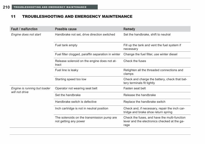
TROUBLESHOOTING AND EMERGENCY MAINTENANCE210
Fault / malfunction Possible cause RemedyEngine does not start Handbrake not set, drive direction switched Set the handbrake, shift to neutral
Fuel tank empty Fill up the tank and vent the fuel system if necessary
Fuel filter clogged, paraffin separation in winter Change the fuel filter, use winter diesel
Release solenoid on the engine does not at-tract
Check the fuses
Fuel line is leaky Retighten all the threaded connections and clamps
Starting speed too low Check and charge the battery, check that bat-tery terminals fit tightly
Engine is running but loader will not drive
Operator not wearing seat belt Fasten seat belt
Set the handbrake Release the handbrake
Handbrake switch is defective Replace the handbrake switch
Inch cartridge is not in neutral position Check and, if necessary, repair the inch car-tridge and brake shoe return spring
The solenoids on the transmission pump are not getting any power
Check the fuses, and have the multi-function lever and the electronics checked at the ga-rage
TROUBLESHOOTING AND EMERGENCY MAINTENANCE11
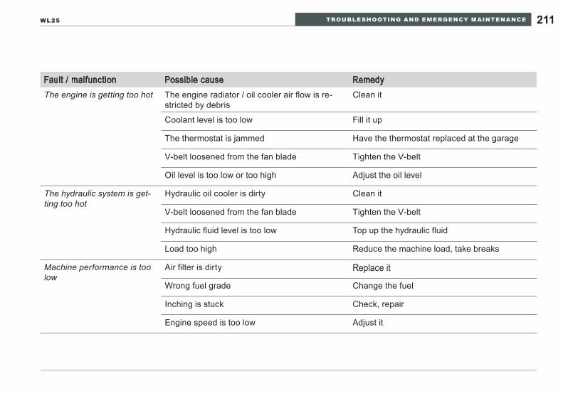
TROUBLESHOOTING AND EMERGENCY MAINTENANCE 211WL25
Fault / malfunction Possible cause RemedyThe engine is getting too hot The engine radiator / oil cooler air flow is re-
stricted by debrisClean it
Coolant level is too low Fill it up
The thermostat is jammed Have the thermostat replaced at the garage
V-belt loosened from the fan blade Tighten the V-belt
Oil level is too low or too high Adjust the oil level
The hydraulic system is get-ting too hot
Hydraulic oil cooler is dirty Clean it
V-belt loosened from the fan blade Tighten the V-belt
Hydraulic fluid level is too low Top up the hydraulic fluid
Load too high Reduce the machine load, take breaks
Machine performance is too low
Air filter is dirty Replace it
Wrong fuel grade Change the fuel
Inching is stuck Check, repair
Engine speed is too low Adjust it

TROUBLESHOOTING AND EMERGENCY MAINTENANCE212
Troubleshooting for transm
ission pump / oil engine
Suction pressure
Control pres-sure
High pressure
Supply pres-sure
»S«Transmission pump
X1/X
2 Transmission pump
MA/M
B Transmission pump
»G«Transmission pump
Suction hoseOil gradeTemperature
Cooler
Rotary direc-tion
Auxiliary pumpSupply pressure valveW
ear
Oil temperatureSpeedConnection (coupling) Drive engine pump
Measuring point
Measuring point
Measuring point
Measuring point
Cause
Cause
Cause
Cause Suction pressure
Supply pressure
Control pressure
Suction pressure
Supply pressure
Filter
SystemAccessoriesBrake / accumulator
Cooler
Wear
Choke
High-pressure valvesnot blocked
Connecting wire
Scavenging valve
Pressure cut-off
Cut-offSpeed max./min.
Clutch
Scavenging needle
Control unit / Solenoid
Transposition
Diesel filter
BrakeW
earAir filter
Waste oil-leakage
Oil temperature
Diesel engineGeneral performance
Oil temperature
CoolerCooler
DA Pressure cut-off for control valve/inching/rotary choke
Tank
Oil motor
Oil
Oil motor
Oil motor
Oil temperature
Bypass valve
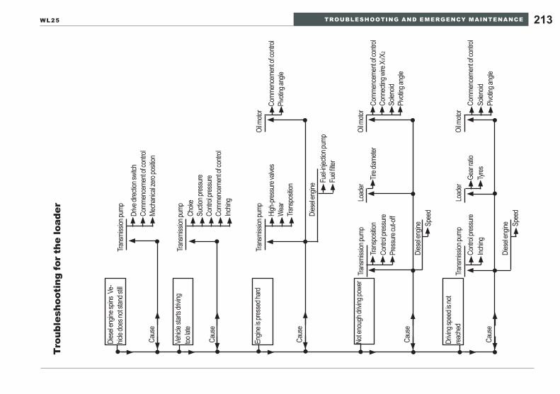
TROUBLESHOOTING AND EMERGENCY MAINTENANCE 213WL25
Tro
uble
shoo
ting
for
the
load
er
Dies
el en
gine s
pins
Ve-
hicle
does
not s
tand s
till
Vehic
le sta
rts dr
iving
too la
te
Engin
e is p
resse
d hard
Not e
noug
h driv
ing po
wer
Drivin
g spe
ed is
not
reach
ed
Trans
miss
ion pu
mp
Trans
miss
ion pu
mp
Trans
miss
ion pu
mp
Trans
miss
ion pu
mp
Trans
miss
ion pu
mp
Load
er
Load
er
Caus
e
Caus
e
Caus
e
Caus
e
Caus
e
Chok
e
Drive
direc
tion s
witch
High
-pres
sure
valve
sCo
mmen
ceme
nt of
contr
ol
Trans
posit
ion
Contr
ol pre
ssure
Tire d
iamete
r
Gear
ratio
Comm
ence
ment
of co
ntrol
Comm
ence
ment
of co
ntrol
Solen
oid
Pivoti
ng an
gle
Sucti
on pr
essu
re
Comm
ence
ment
of co
ntrol
Wea
rPiv
oting
angle
Contr
ol pre
ssure
Inchin
gTy
res
Conn
ectin
g wire
X 1/X
2
Solen
oid
Pivoti
ng an
gle
Fuel-
injec
tion p
ump
Contr
ol pre
ssure
Mech
anica
l zero
posit
ion
Trans
posit
ion
Dies
el en
gine
Pres
sure
cut-o
ff
Dies
el en
gine
Dies
el en
gine Sp
eed
Spee
d
Fuel
filter
Comm
ence
ment
of co
ntrol
Inchin
g
Oil m
otor
Oil m
otor
Oil m
otor
SAFETY INSTRUCTIONS FOR REPAIRS214
SAFETY INSTRUCTIONS FOR REPAIRS12
Observe in particular:
The basic safety instructions.• The basic safety instructions for servicing and inspec-• tion.All warning signs and instructions attached to the load-• er.That the descriptions of work processes provide the • necessary instructions only for experienced specialized personnel.That the operator’s manual is always kept with the • loader
Repair personnel:
Repair personnel must have specialized knowledge and • experience in repairing this or comparable loaders.Should knowledge be lacking, training by experienced • repair, e.g. Wacker Neuson Service, should be carried out.
General safety regulations for repairs12.1
Operator’s manual:
Carry out repairs only if you have read and understood • the operator’s manual.
The »Safety instructions for repairs« section does not consist of instructions for repairs, but rather of safety instructions which, in addition to the gener-ally valid safety regulations for repair work, refer to hazards that could occur during repair work, and of notes which should prevent the machine from being damaged during repairs.Specific repair instructions are not included in this operator’s manual.
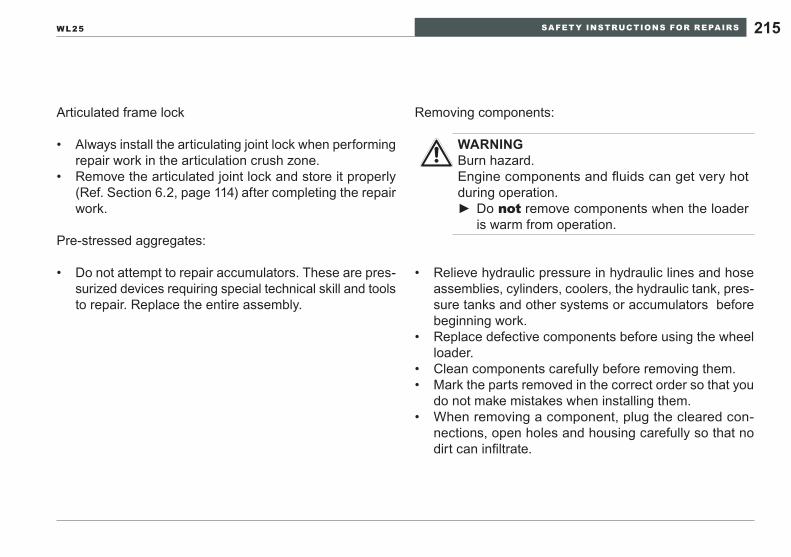
SAFETY INSTRUCTIONS FOR REPAIRS 215WL25
Articulated frame lock
Always install the articulating joint lock when performing • repair work in the articulation crush zone.Remove the articulated joint lock and store it properly • (Ref. Section 6.2, page 114) after completing the repair work.
Pre-stressed aggregates:
Do not attempt to repair accumulators. These are pres-• surized devices requiring special technical skill and tools to repair. Replace the entire assembly.
Removing components:
Relieve hydraulic pressure in hydraulic lines and hose • assemblies, cylinders, coolers, the hydraulic tank, pres-sure tanks and other systems or accumulators before beginning work.Replace defective components before using the wheel • loader.Clean components carefully before removing them.• Mark the parts removed in the correct order so that you • do not make mistakes when installing them.When removing a component, plug the cleared con-• nections, open holes and housing carefully so that no dirt can infiltrate.
WARNINGBurn hazard.Engine components and fluids can get very hot during operation.
Do ► not remove components when the loader is warm from operation.
SAFETY INSTRUCTIONS FOR REPAIRS216
Do not remove seals or sealing wax:
Changing rated pressures for relief valves is prohibited • without the express consent of Wacker Neuson.Do not damage or remove seals and sealing wax on • the engine, the pressure limiting valves and accumula-tors.If an area is repainted and a safety label is damaged or • obliterated, replace the label before using the machine. If a removed component or assembly had a safety mes-sage label, replace the label with the replacement part. Your Wacker Neuson dealer can help you to get replace-ment labels for your machine
After completing the repair:
Put protective paint on all uncoated machine parts to • prevent corrosion damage.Install the cab mounting screws again after the repair • work has been completed.Reattach all safety devices, covers and noise/vibration • insulation after repair work has been completed.Check the functioning of the loader, in particular the • parts repaired in trial operation. Make sure that no one is in the loader‘s danger area.Do not approve the loader for operation until all the • loader‘s areas function properly.
SAFETY INSTRUCTIONS FOR REPAIRS 217WL25
Engine12.2
Perform repair work only if the loader is secured as de-• scribed in Section 9, page 125 »Securing the loader«.
Welding work12.3
A certified trained welder shall perform welding work.• Only certain authorized individuals under the supervi-• sion of a competent person may weld containers which contain or have contained substances that are com-bustible, promote combustion, are explosive, or can, during welding, produce vapor, gas, mist or dust that are hazardous to health. Should you have problems or questions, it is imperative that you consult the Wacker Neuson Service.
WARNINGImproper handling of the ROPS/FOPS can com-promise its integrity.
Do not drill, weld, straighten, or bend the ROPS ►/ FOPS protective structures.Allow only trained authorized personnel to install ►new ROPS / FOPS structures.
SAFETY INSTRUCTIONS FOR REPAIRS218
Before performing welding work on the loader
Disconnect the battery as described in this operator’s • manual.Disconnect the positive pole (terminal B+) on the gen-• erator.Switch OFF the battery disconnect switch (if present).• Protect bare terminals and connections against short-• circuiting.Attach the welding grounding terminal in the immedi-• ate vicinity of the welding site. Do not allow the welding current to pass through gears, bolts, articulated joints or hydraulic cylinders.
After welding has been completed:
Reconnect all the electrical connections and check that • they function.Connect the battery as described in this operator’s • manual.
SAFETY INSTRUCTIONS FOR REPAIRS 219WL25
Hydraulic system12.4
Before performing repair work, relieve the pressure in • the hydraulic system as described in Section 8, page 122 »Relieving residual pressure in the hydraulic system«.Replace damaged and leaky hydraulic lines and hoses • with new ones. Do not use used hoses.Replace hydraulic hoses after six years of use.• Dispose of any leaking oil and waste containing oil in • an ecologically sound manner.Observe the • »Basic safety instructions for servicing and inspection«, page 126.
Brakes12.5
Repair work on brakes may only be performed by quali-• fied technicians.Using a brake fluid other than the one specified by the • manufacturer is prohibited.Observe the notes on health hazards and environmental • protection when working with brake fluid.Perform repair work on the brakes only if the loader is • secured as described in Section 9. page 125 »Securing the loader«.

Final shutdown oF the loader / decommissioning220
FINAL SHUTDOWN OF THE LOADER / DECOMMISSIONING13
Should you no longer plan to use the loader as intended, make sure that it is shut down, i.e. decommissioned, and disposed of according to the valid regulations.
Before disposing of the loader:
Observe all safety procedures regarding shutdown of • the loader.Make sure that the loader cannot be operated from the • time of shutdown to further disposal.Make sure that no environmentally hazardous operating • fluids or fuel escape and that the machine poses no other dangers in the place where it is standing.Protect the loader against unauthorized use. Close all • openings (doors, windows, engine enclosure) and secure the loader as described in Section 9, page 125 »Secur-ing the loader«.Attach all the safety devices.• Eliminate leaks on the engine, tanks and hydraulic sys-• tem.Remove the battery.• Store the loader in a place protected against access by • unauthorized persons.
eNVIRONmeNTAl NOTeAvoid environmental damage. Do not allow oil and waste containing oil to spill on the ground or get into bodies of water!Dispose of different materials and operating fluids/auxiliary materials separately and in an ecologically sound manner.
FINAL SHUTDOWN OF THE LOADER / DECOMMISSIONING 221WL25
Disposing of the loader:
Subsequent recycling of the loader must take place in • accordance with the current state of the art at the time of recycling, taking into account the accident prevention regulations.Dispose of all parts at the sites provided for them, de-• pending on the material.Take care to separate the materials when recycling.• Make sure that operating and auxiliary aids are disposed • of in an ecologically sound manner.
APPENDIx222
APPENDIx14
Ordering replacement parts14.1
Wacker Neuson- machine type• Specify the serial number of the machine (see rating • plate) For the engine, specify the respective engine numberItem number and designation of the replacement part• Address with telephone number (in the event of ques-• tions)Customer number (if available)• Name of the orderer•
We reserve the right to change the replacement parts list.
Always provide the following data for ordering re-placement parts. This is the only way we can assure smooth processing of your order and delivery of the replacement parts.
Use only »original Wacker Neuson replacement parts« for your loader.This is especially necessary in the case of hydraulic hoses. Use only original hydraulic hoses or hydrau-lic hoses of comparable quality.
APPENDIx 223WL25
Loader type:
Vehicle ID no.:
Engine type:
Engine no.:
Delivery date:
Importer (name; address):
Service garage (name; address):
Enter the most important data for your loader on this page. In this way, you can quickly access the vehicle ID no. and other important data when order-ing replacement parts.
APPENDIx224
1st Inspection
Performed on:
Operating hours:
Stamp / signature of the garage
2nd Inspection
Performed on:
Operating hours:
Stamp / signature of the garage
3rd Inspection
Performed on:
Operating hours:
Stamp / signature of the garage
Inspection verification14.2
Enter the inspections as they are performed.
APPENDIx 225WL25
4th Inspection
Performed on:
Operating hours:
Stamp / signature of the garage
6th Inspection
Performed on:
Operating hours:
Stamp / signature of the garage
5th Inspection
Performed on:
Operating hours:
Stamp / signature of the garage
7th Inspection
Performed on:
Operating hours:
Stamp / signature of the garage
APPENDIx226
8th Inspection
Performed on:
Operating hours:
Stamp / signature of the garage
10th Inspection
Performed on:
Operating hours:
Stamp / signature of the garage
9th Inspection
Performed on:
Operating hours:
Stamp / signature of the garage
11th Inspection
Performed on:
Operating hours:
Stamp / signature of the garage

APPENDIx 227WL25
For personal notes
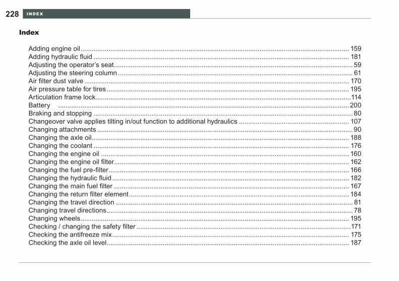
INDEx228
Index
Adding engine oil ................................................................................................................................................ 159Adding hydraulic fluid ......................................................................................................................................... 181Adjusting the operator’s seat ................................................................................................................................ 59Adjusting the steering column .............................................................................................................................. 61Air filter dust valve .............................................................................................................................................. 170Air pressure table for tires .................................................................................................................................. 195Articulation frame lock .........................................................................................................................................114Battery ............................................................................................................................................................ 200Braking and stopping ........................................................................................................................................... 80Changeover valve applies tilting in/out function to additional hydraulics ........................................................... 107Changing attachments ......................................................................................................................................... 90Changing the axle oil .......................................................................................................................................... 188Changing the coolant ......................................................................................................................................... 176Changing the engine oil ..................................................................................................................................... 160Changing the engine oil filter .............................................................................................................................. 162Changing the fuel pre-filter ................................................................................................................................. 166Changing the hydraulic fluid ............................................................................................................................... 182Changing the main fuel filter .............................................................................................................................. 167Changing the return filter element ...................................................................................................................... 184Changing the travel direction ............................................................................................................................... 81Changing travel directions .................................................................................................................................... 78Changing wheels ................................................................................................................................................ 195Checking / changing the safety filter ...................................................................................................................171Checking the antifreeze mix ............................................................................................................................... 175Checking the axle oil level .................................................................................................................................. 187
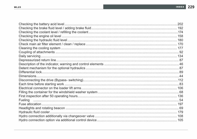
INDEx 229WL25
Checking the battery acid level .......................................................................................................................... 202Checking the brake fluid level / adding brake fluid ............................................................................................. 192Checking the coolant level / refilling the coolant .................................................................................................174Checking the engine oil level ............................................................................................................................. 158Checking the hydraulic fluid level ....................................................................................................................... 180Check main air filter element / clean / replace ................................................................................................... 170Cleaning the cooling system .............................................................................................................................. 177Coupling of attachments ...................................................................................................................................... 92Daily servicing .................................................................................................................................................... 134Depressurized return line ..................................................................................................................................... 87Description of the indicator, warning and control elements ................................................................................. 46Detent mechanism for the optional hydraulics ..................................................................................................... 87Differential lock..................................................................................................................................................... 89Dimensions........................................................................................................................................................... 44Disconnecting the drive (Bypass- switching) .......................................................................................................112Each time before starting work ............................................................................................................................ 83Electrical connector on the loader lift arms ........................................................................................................ 106Filling the container for the windshield washer system ........................................................................................ 68First inspection after 50 operating hours ............................................................................................................ 136Fueling .............................................................................................................................................................. 54Fuse allocation ................................................................................................................................................... 197Headlights and rotating beacon ........................................................................................................................... 69Hydraulic fluid cooler .......................................................................................................................................... 179Hydro connection additionally via changeover valve ......................................................................................... 108Hydro connection option via additional control device ....................................................................................... 105

INDEx230
If the engine does not start .................................................................................................................................. 75Independent driving onto the transport device ....................................................................................................118Inflating the tires ................................................................................................................................................. 194Inspection after 500 operating hours ................................................................................................................. 138Inspection intervals .............................................................................................................................................141Jump-starting / emergency starting ................................................................................................................... 204Lighting system and forward warning device ....................................................................................................... 66Loader data .......................................................................................................................................................... 41Loader lift arm damping ..................................................................................................................................... 104Loader lift arms locking system ............................................................................................................................ 88Loader Tie-Down ................................................................................................................................................118Loader travel ........................................................................................................................................................ 80Loading on a transport vehicle ............................................................................................................................116Loading with crane ..............................................................................................................................................116Lubrication schedule .......................................................................................................................................... 146Operating lever for Loader lift arms ...................................................................................................................... 84Operating lever for the optional hydraulics ........................................................................................................... 86Optional multi-function lever for multiple functions ............................................................................................ 109ROPS / FOPS - protective structures ................................................................................................................... 22Safety belt ............................................................................................................................................................ 62Servicing the air filter system ............................................................................................................................. 169Servicing the axles ............................................................................................................................................. 186Servicing the battery .......................................................................................................................................... 201Servicing the brakes ........................................................................................................................................... 191Servicing the electrical system........................................................................................................................... 197
INDEx 231WL25
Servicing the engine .......................................................................................................................................... 158Servicing the fuel system ................................................................................................................................... 164Servicing the hydraulic system ........................................................................................................................... 178Servicing the tires and wheels ........................................................................................................................... 193Servicing the water separator ............................................................................................................................ 165Specifications and filling quantities .....................................................................................................................151Starting the engine ............................................................................................................................................... 73Switching gears .................................................................................................................................................... 79Technical descriptions .......................................................................................................................................... 39Tilting the operator’s platform............................................................................................................................. 154Tip-overs ............................................................................................................................................................ 101Towing equipment ...............................................................................................................................................111Troubleshooting and emergency maintenance .................................................................................................. 210Troubleshooting for the loader ........................................................................................................................... 213Troubleshooting for transmission pump / oil engine ........................................................................................... 212Uncoupling attachments....................................................................................................................................... 94Ventilation filter / hydraulic fluid filler neck .......................................................................................................... 179Venting the fuel system ...................................................................................................................................... 168Venting the hydraulic system .............................................................................................................................. 186Weekly servicing ................................................................................................................................................ 135Wipers and windshield washer system ................................................................................................................ 67Working with the bucket ....................................................................................................................................... 98

LIST OF FIGURES232
List of figures
Fig. 1 Document pocket .................................................................................................................................. 11Fig. 2 Transport of large bales or packaged goods ........................................................................................ 23Fig. 3 Location of the Safety labels ................................................................................................................. 29Fig. 4 Fire extinguisher ................................................................................................................................... 34Fig. 5 Attaching the rotating beacon ............................................................................................................... 34Fig. 6 Seat belt ................................................................................................................................................ 35Fig. 7 Emergency exit ..................................................................................................................................... 36Fig. 8 Battery disconnect switch ..................................................................................................................... 37Fig. 9 Lever for the locking mechanism of the Loader lift arm ........................................................................ 38Fig. 10 Vehicle ID .............................................................................................................................................. 43Fig. 11 Dimensions ........................................................................................................................................... 44Fig. 12 Operating elements ............................................................................................................................... 46Fig. 13 Control and warning lights .................................................................................................................... 48Fig. 14 Switches / rocker switches .................................................................................................................... 50Fig. 15 Indicator devices ................................................................................................................................... 52Fig. 16 Fuel filler neck ....................................................................................................................................... 55Fig. 17 Cab door locking ................................................................................................................................... 58Fig. 18 Releasing locked cab doors .................................................................................................................. 58Fig. 19 Rear window locking ............................................................................................................................. 59Fig. 20 Adjusting the operator’s seat ................................................................................................................ 60Fig. 21 Adjusting the steering column ............................................................................................................... 61Fig. 22 Buckling the seat belt ............................................................................................................................ 63Fig. 23 Adjusting the seat belt ........................................................................................................................... 64
LIST OF FIGURES 233WL25
Fig. 24 Lighting / forward warning device ......................................................................................................... 66Fig. 25 Switches for windshield wipers ............................................................................................................. 67Fig. 26 Location of the windshield washer container ........................................................................................ 68Fig. 27 Headlight and rotating beacon switches ............................................................................................... 69Fig. 28 Heating controller .................................................................................................................................. 71Fig. 29 Ventilation jets ....................................................................................................................................... 72Fig. 30 Starting switch ...................................................................................................................................... 74Fig. 31 Changing direction ................................................................................................................................ 79Fig. 32 Operating lever for Loader lift arms ...................................................................................................... 85Fig. 33 Operating lever for the optional hydraulics .......................................................................................... 86Fig. 34 Hydraulic connections ........................................................................................................................... 86Fig. 35 Depressurized return line ...................................................................................................................... 87Fig. 36 Lever for the locking mechanism of the Loader lift arms ...................................................................... 88Fig. 37 Switch for differential lock ..................................................................................................................... 89Fig. 38 Coupling and uncoupling tools .............................................................................................................. 93Fig. 39 Control lever movements ...................................................................................................................... 96Fig. 40 Level indicator ....................................................................................................................................... 97Fig. 41 Loading work 1 ...................................................................................................................................... 98Fig. 42 Loading work 2 ...................................................................................................................................... 99Fig. 43 Loading work 3 ...................................................................................................................................... 99Fig. 44 Excavation work 4 ............................................................................................................................... 100Fig. 45 Excavation work 5 ............................................................................................................................... 100Fig. 46 Switch for lift frame vibration damping ................................................................................................ 105
LIST OF FIGURES234
Fig. 47 Additional control lever ........................................................................................................................ 105Fig. 48 Electrical connector on the loader lift arms ........................................................................................ 106Fig. 49 Switch for the electrical connector on the loader lift arms .................................................................. 106Fig. 50 Switch for changeover valve ............................................................................................................... 107Fig. 51 Additional hydraulic connections......................................................................................................... 108Fig. 52 Optional multi-function lever ............................................................................................................... 109Fig. 53 Towing equipment ................................................................................................................................111Fig. 54 Disconnecting the drive .......................................................................................................................112Fig. 55 Articulation frame lock .........................................................................................................................115Fig. 56 Attachment point label .........................................................................................................................117Fig. 57 Attachment points ................................................................................................................................117Fig. 58 Tie down point label .............................................................................................................................119Fig. 59 Tie down points ....................................................................................................................................119Fig. 60 Tying down the loader ......................................................................................................................... 120Fig. 61 Reducing residual pressure ................................................................................................................ 123Fig. 62 Load holding control valve .................................................................................................................. 124Fig. 63 Points of lubrication ............................................................................................................................. 146Fig. 64 Handle for the engine enclosure ......................................................................................................... 153Fig. 65 Cab tilt lever ........................................................................................................................................ 155Fig. 66 Position of the cab mounting screws .................................................................................................. 156Fig. 67 Cab safety support .............................................................................................................................. 157Fig. 68 Checking the engine oil / filling the oil ................................................................................................. 158Fig. 69 Engine oil drain opening ..................................................................................................................... 161
LIST OF FIGURES 235WL25
Fig. 70 Location of the engine oil filter ............................................................................................................ 163Fig. 71 Engine oil filter .................................................................................................................................... 163Fig. 72 Water separator .................................................................................................................................. 165Fig. 73 Fuel pre-filter, main fuel filter............................................................................................................... 166Fig. 74 Changing the main fuel filter ............................................................................................................... 167Fig. 75 Venting the fuel system ....................................................................................................................... 168Fig. 76 Location of the air filter ........................................................................................................................ 170Fig. 77 Air filter elements ................................................................................................................................ 170Fig. 78 Radiator............................................................................................................................................... 172Fig. 79 Engine temperature sensor ................................................................................................................. 173Fig. 80 Hydraulic oil temperature sensor ........................................................................................................ 173Fig. 81 Radiator opening ................................................................................................................................. 175Fig. 82 Checking the antifreeze mix................................................................................................................ 175Fig. 83 Cleaning the cooling system ............................................................................................................... 177Fig. 84 Hydraulic fluid cooler ........................................................................................................................... 179Fig. 85 Ventilation filter .................................................................................................................................... 181Fig. 86 Hydraulic fluid dip stick ....................................................................................................................... 181Fig. 87 Hydraulic fluid drain plugs ................................................................................................................... 183Fig. 88 Return filter.......................................................................................................................................... 185Fig. 89 Filter insert .......................................................................................................................................... 185Fig. 90 Checking and fill plug on the differential ............................................................................................. 187Fig. 91 Oil drain plug on the differential .......................................................................................................... 188Fig. 92 Cab vent filter ...................................................................................................................................... 190

LIST OF FIGURES236
Fig. 93 Brake fluid container ........................................................................................................................... 193Fig. 94 Master fuse ......................................................................................................................................... 198Fig. 95 Fuse boxes .......................................................................................................................................... 198Fig. 96 Location of the battery ........................................................................................................................ 201Fig. 97 Connecting the jumper cables ............................................................................................................ 205

LIST OF FIGURES 237WL25

Wacker Construction Equipment AGPreußenstraße 4180809 MünchenTel. +49 89 35402-0Fax +49 89 35402-390
Wacker Neuson CorporationP.O. Box 9007Menomonee Falls, WI 53052-9007Tel. +1 262 255-0500Fax +1 262 255-0550Tel.: 800 770-0957
Wacker Machinery (HK) Ltd.Skyline Tower, Suite 2303, 23/F39 Wang Kwong Road, Kwoloon BayHong KongTel.: +852 3188 5506Fax: +852 2406 6021
Art.-Nr.: 2843894