Embed Size (px)
Citation preview
www.wackergroup.com
Operator´s Manual
Vibratory plate
DPU 5045H
0203092en 001
11.2004

H00556GB 1
CONTENTS
Type Item no.
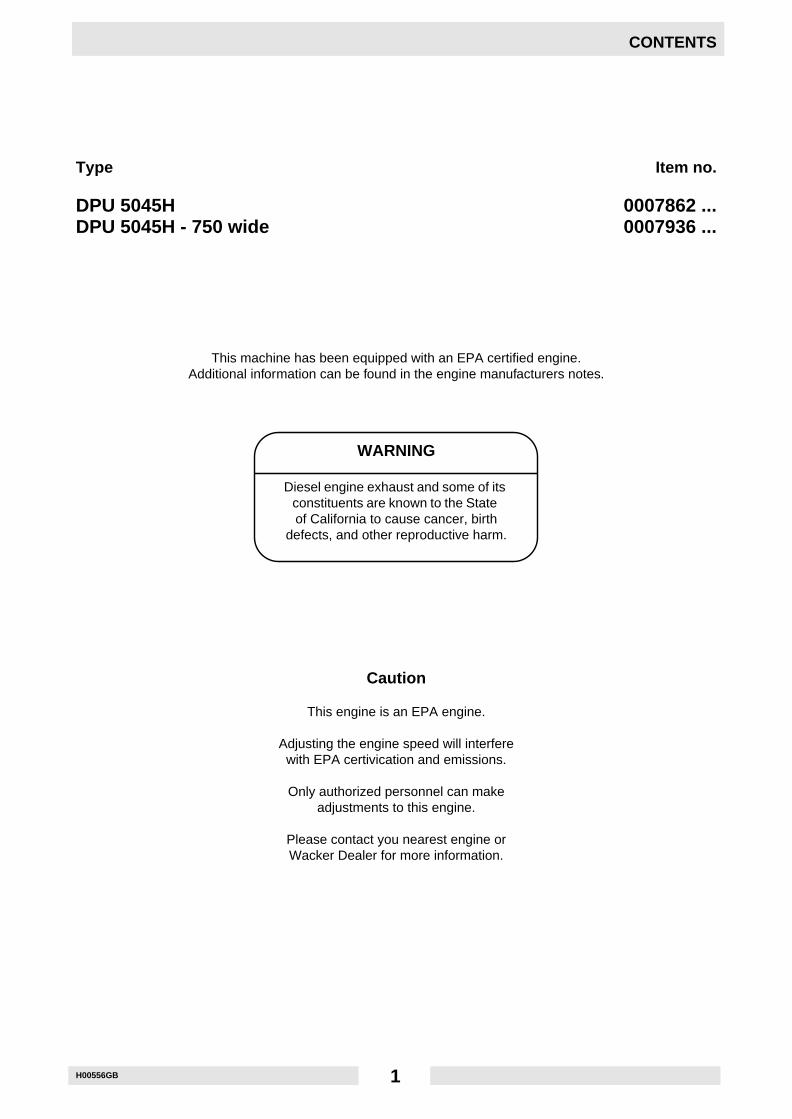
DPU 5045H 0007862 ...DPU 5045H - 750 wide 0007936 ...
This machine has been equipped with an EPA certified engine.Additional information can be found in the engine manufacturers notes.
Caution
This engine is an EPA engine.
Adjusting the engine speed will interferewith EPA certivication and emissions.
Only authorized personnel can makeadjustments to this engine.
Please contact you nearest engine orWacker Dealer for more information.
WARNING
Diesel engine exhaust and some of itsconstituents are known to the Stateof California to cause cancer, birth
defects, and other reproductive harm.

2
T00778GB 3
FOREWORD
Foreword
For your own safety and protection from bodily injuries, carefully read, understand and follow the safety instruc-tions in this manual.
Please operate and maintain your Wacker machine in accordance with the instructions in this manual.
Defective machine parts are to be replaced as soon as possible.
All rights, especially the right for copying and distribution are reserved.
Copyright by Wacker Construction Equipment AG.
No part of this publication may be reproduced in any form or by any means, electronic or mechanical, includingphotocopying, without express permission in writing from Wacker Construction Equipment AG.
Any type of reproduction, distribution or saving on data carriers of any type or method not authorized by Wackerrepresents an infringement of valid copyrights and will be prosecuted.We expressly reserve the right to technical modifications- even without express due notice - which aim at im-proving our machines or their safety standards.
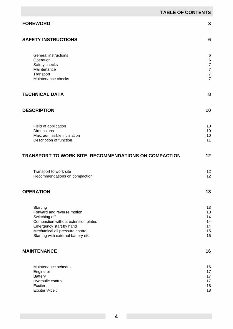
TABLE OF CONTENTS
FOREWORD 3
SAFETY INSTRUCTIONS 6
General instructions 6Operation 6Safety checks 7Maintenance 7Transport 7Maintenance checks 7
TECHNICAL DATA 8
DESCRIPTION 10
Field of application 10Dimensions 10Max. admissible inclination 10Description of function 11
TRANSPORT TO WORK SITE, RECOMMENDATIONS ON COMPACTION 12
Transport to work site 12Recommendations on compaction 12
OPERATION 13
Starting 13Forward and reverse motion 13Switching off 14Compaction without extension plates 14Emergency start by hand 14Mechanical oil pressure control 15Starting with external battery etc. 15
MAINTENANCE 16
Maintenance schedule 16Engine oil 17Battery 17Hydraulic control 17Exciter 18Exciter V-belt 18
4

TABLE OF CONTENTS
FAULTS 19
Forward speed too low 19Reverse speed too low 19No reverse motion 19Loss of hydraulic oil 19Battery-charge warning lamp does not go off 19Engine does not start 19
ELECTRIC WIRING DIAGRAM 20
EC - CONFORMITY-CERTIFICATE 21
5
SV00006GB 6
SAFETY INSTRUCTIONS
SAFETY INSTRUCTIONS FOR THE USE OF VIBRATORYPLATES WITH COMBUSTION ENGINES
General instructions
1. Vibratory plates may only be operated by persons who
* are at least 18 years of age* are physically and mentally fit for this job* have been instructed in guiding vibratory plates and proved their ability for the job to the employer* may be expected to carry out the job they are charged with carefully.The persons must be assigned the job of guiding vibratory plates by the employer.
2. Vibratory plates may only be used for compaction jobs. Both the manufacturer’s operating instructionsand these safety instructions have to be observed.
3. The persons charged with the operation of vibratory plates have to be made familiar with the necessarysafety measures relating to the machine. In case of extraordinary uses the employer shall give the nec-essary additional instructions.
4. It is possible that this vibratory plate exceeds the admissible sound level of 89 dB (A). According to therules for the prevention of accidents regarding emission of noise, the employees have to wear ear pro-tection if the sound level reaches 89 dB (A) or more.
Operation
1. When starting a diesel engine with a starter crank make sure you have assumed a proper position withrespect to the engine and that your hands are placed properly on the crank.
☛ATTENTION! Only use the original engine manufacturer’s safety starting crank.
To avoid a possible return kick, turn safety starting crank through with full force untilthe engine starts running.
2. The functioning of operating levers or elements is not to be influenced or rendered ineffective.3. During operation the operator may not leave the control elements.4. The operator has to stop the engine of the vibratory plate before going on breaks. The machine has to
be placed such that it cannot turn over.5. Stop engine before filling fuel tank. When refilling fuel tank, do not allow fuel to come into contact with
the hot parts of the engine or spill onto the ground.6. Do not smoke or handle open fire near this machine.7. The tank lid must fit tightly. Shut off fuel cock, if available when stopping the engine. For long distance
transports of machine operated by fuel or fuel - mixtures, the fuel tank has to be drained completely.
☛ATTENTION! Leaky fuel tanks may cause explosions and must therefore be replaced immediately.
8. Do not operate the machine in areas where explosions may occur.9. Make sure that sufficient fresh air is available when operating vibratory plates with combustion engines
in enclosed areas, tunnels, adits and deep trenches.10. During operation keep your hands, feet and clothes away from the moving parts of the vibraton plate.
Wear safety shoes, and eye protection glasses in case of trench operation where falling sand stonesmaybe ejected.
11. When working near the edges of breaks, pits, slopes, trenches and platforms, vibratory plates are to beoperated such that there is no danger of their turning over or dropping in.
SV00006GB 7
SAFETY INSTRUCTIONS
12. Make sure the soil or subsoil to be compacted has a high enough load carrying capacity.13. Use appropriate protective clothing while working or while carrying out maintenance work.14. When traveling backwards the operator has to guide the vibration plate laterally by its guide handle so
thathewillnotbesqueezedbetweenthehandleandapossibleobstacle.Specialcare is requiredwhenworking on uneven ground or when compacting coarse material. Make sure of a firm stand when operatingthe machine under such conditons.
15. Vibratory plates are to be guided such that hand injuries caused by solid objects are avoided.16. Vibratory plates have to be guided such that their stability is guaranteed.17. Machines with integrated transport trolley may not be parked or stored on the trolley. This device has
only been designed to transport the machine.
Safety checks
1. Vibratory plates may only be operated with all safety devices installed.2. Before starting operation, the operator has to check that all control and safety devices function properly.3. Immediately notify your supervisor or superintendent if you have determined defects in the safety devic-
es or other defects which could endanger the safe operation of the machine or which could endangerthe environment.
4. In case of defects jeopardizing the operational safety of the vibration plate, the machine has to bestopped immediately.
5. Process materials and operating fuels must be stowed away in receptacles or containers marked ac-cording to the respective manufacturers specifications.
Maintenance
1. Only use original spare parts. Modifications to this machine, including the adjustment of the maximumengine speed set by the manufacturer, are subject to the express approval of Wacker. In case of non-observance all liabilities shall be refused.
2. All drive units have to be switched off before carrying out maintenance jobs. Deviations from this are onlyallowed if the maintenance or jobs require a running engine.
3. When working on vibratory plates equipped with electric starter, disconnect battery before carrying outmaintenance or repair jobs on the electric parts of the machine.
4. Remove pressure from hydraulic lines before working on them. Caution: take care when removing hy-draulic lines, for the oil may be very hot (up. over 80o C). Precautions are to be taken to prevent oil fromsplashing into the operator’s eyes.
5. As soon as maintenance and repair jobs have been completed all safety devices have to be reinstalledproperly.
6. Do not hose down the machine with water after each use to avoid possible malfunctions. Do not use highpressure washers nor chemical products.
Transport
1. During transport, loading and unloading of vibration plates by means of lifting devices, appropriate sling-ing means or hooks have to be used on the lifting points provided for this purpose on the vibratory plate.
2. The load-carrying capacity of the loading ramps has to be sufficient and the ramps have to be securesuch that they cannot turn over. Make sure that no one be endangered by machines turning over by slip-ping or by moving machine parts.
3. When being transported on vehicles, precautions have to be taken that vibration plates do not slip or turnover.
Maintenance checks
According to the conditions and frequency of use, vibratory plates have to be checked for safe operation atleast once a year by skilled technicians, such as those found at Wacker-service depots and have to be repairedif necessary.Please also observe the corresponding rules and regulations valid in your country.
TD00556GB 8
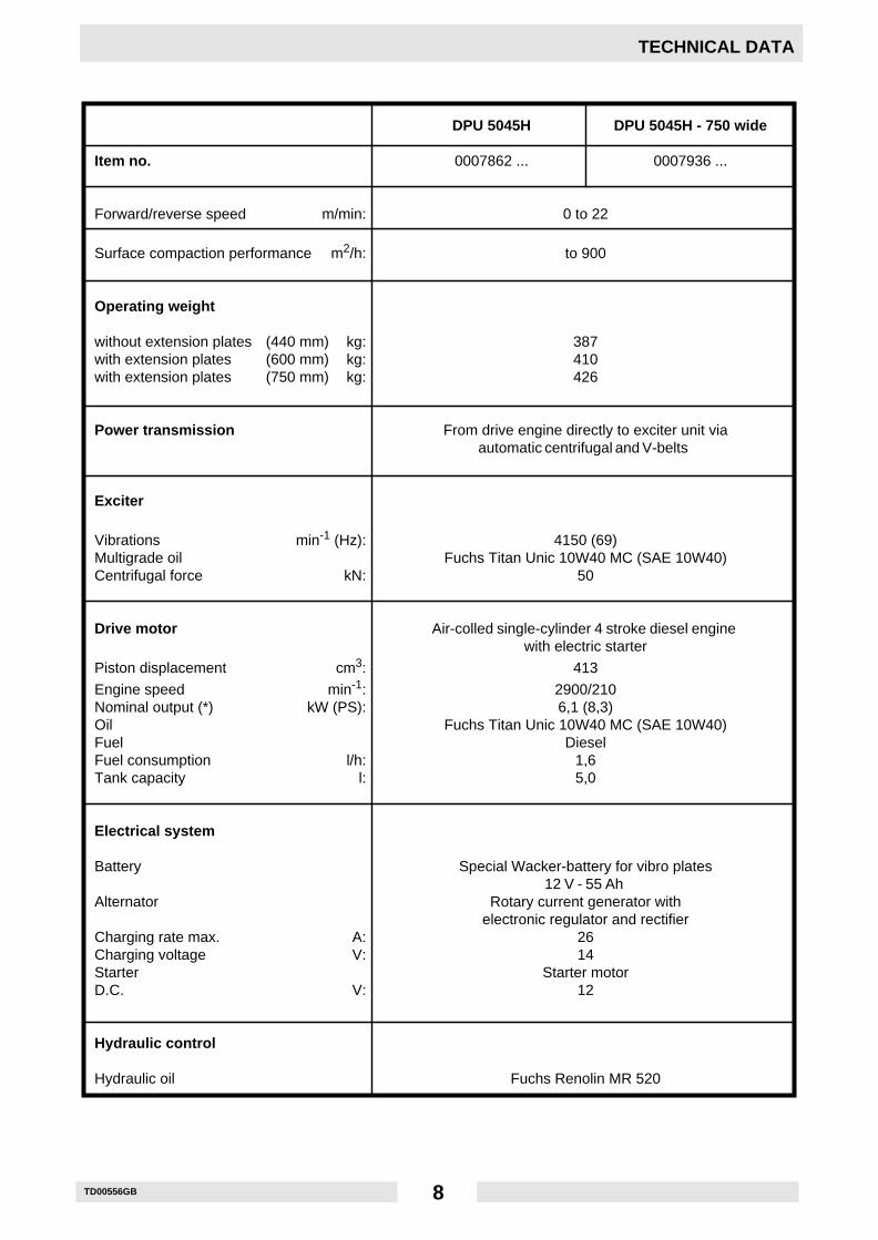
TECHNICAL DATA
DPU 5045H DPU 5045H - 750 wide
Item no. 0007862 ... 0007936 ...
Forward/reverse speed m/min: 0 to 22
Surface compaction performance m2/h: to 900
Operating weight
without extension plates (440 mm) kg: 387with extension plates (600 mm) kg: 410with extension plates (750 mm) kg: 426
Power transmission From drive engine directly to exciter unit viaautomatic centrifugal and V-belts
Exciter
Vibrations min-1 (Hz): 4150 (69)Multigrade oil Fuchs Titan Unic 10W40 MC (SAE 10W40)Centrifugal force kN: 50
Drive motor Air-colled single-cylinder 4 stroke diesel enginewith electric starter
Piston displacement cm3: 413
Engine speed min-1: 2900/210Nominal output (*) kW (PS): 6,1 (8,3)Oil Fuchs Titan Unic 10W40 MC (SAE 10W40)Fuel DieselFuel consumption l/h: 1,6Tank capacity l: 5,0
Electrical system
Battery Special Wacker-battery for vibro plates12 V - 55 Ah
Alternator Rotary current generator withelectronic regulator and rectifier
Charging rate max. A: 26Charging voltage V: 14Starter Starter motorD.C. V: 12
Hydraulic control
Hydraulic oil Fuchs Renolin MR 520

TD00556GB 9
TECHNICAL DATA
(*) In accordance with the installed useful outlet power according to Directive 2000/14/EG.
The sound pressure level at the operator‘s working place, determined according to the EN ISO 11204 standard,is equal to LpA = 90 dB(A)
The weighted effective acceleration value, determined according to EN 1033 is 6 m/s2.
The sound and vibration measurements were carried out and obtained with the machine working on crushedgravel at nominal engine speed.
T00464GB 10
DESCRIPTION
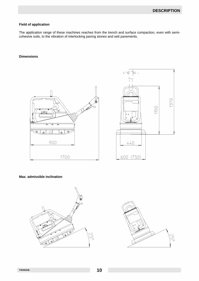
Field of application
The application range of these machines reaches from the trench and surface compaction, even with semi-cohesive soils, to the vibration of interlocking paving stones and sett pavements.
Dimensions
Max. admissible inclination
T00464GB 11
DESCRIPTION
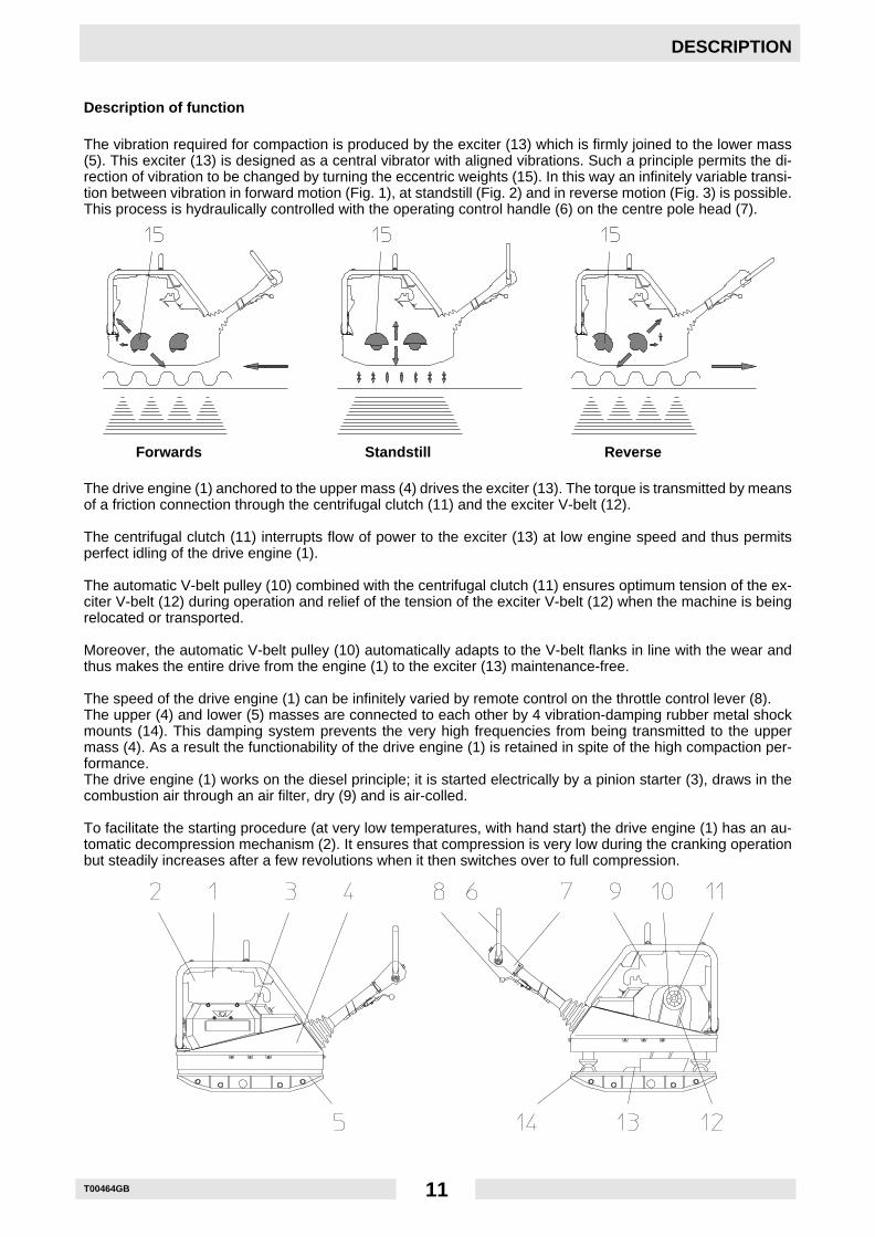
Description of function
The vibration required for compaction is produced by the exciter (13) which is firmly joined to the lower mass(5). This exciter (13) is designed as a central vibrator with aligned vibrations. Such a principle permits the di-rection of vibration to be changed by turning the eccentric weights (15). In this way an infinitely variable transi-tion between vibration in forward motion (Fig. 1), at standstill (Fig. 2) and in reverse motion (Fig. 3) is possible.This process is hydraulically controlled with the operating control handle (6) on the centre pole head (7).
Forwards Standstill Reverse
The drive engine (1) anchored to the upper mass (4) drives the exciter (13). The torque is transmitted by meansof a friction connection through the centrifugal clutch (11) and the exciter V-belt (12).
The centrifugal clutch (11) interrupts flow of power to the exciter (13) at low engine speed and thus permitsperfect idling of the drive engine (1).
The automatic V-belt pulley (10) combined with the centrifugal clutch (11) ensures optimum tension of the ex-citer V-belt (12) during operation and relief of the tension of the exciter V-belt (12) when the machine is beingrelocated or transported.
Moreover, the automatic V-belt pulley (10) automatically adapts to the V-belt flanks in line with the wear andthus makes the entire drive from the engine (1) to the exciter (13) maintenance-free.
The speed of the drive engine (1) can be infinitely varied by remote control on the throttle control lever (8).The upper (4) and lower (5) masses are connected to each other by 4 vibration-damping rubber metal shockmounts (14). This damping system prevents the very high frequencies from being transmitted to the uppermass (4). As a result the functionability of the drive engine (1) is retained in spite of the high compaction per-formance.The drive engine (1) works on the diesel principle; it is started electrically by a pinion starter (3), draws in thecombustion air through an air filter, dry (9) and is air-colled.
To facilitate the starting procedure (at very low temperatures, with hand start) the drive engine (1) has an au-tomatic decompression mechanism (2). It ensures that compression is very low during the cranking operationbut steadily increases after a few revolutions when it then switches over to full compression.
T00465GB 12
TRANSPORT TO WORK SITE, RECOMMENDATIONS ON COMPACTION
Transport to work site
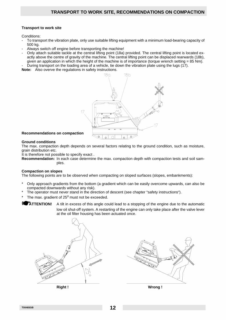
Conditions:- To transport the vibration plate, only use suitable lifting equipment with a minimum load-bearing capacity of
500 kg.- Always switch off engine before transporting the machine!- Only attach suitable tackle at the central lifting point (18a) provided. The central lifting point is located ex-
actly above the centre of gravity of the machine. The central lifting point can be displaced rearwards (18b),given an application in which the height of the machine is of importance (torque wrench setting = 85 Nm).
- During transport on the loading area of a vehicle, tie down the vibration plate using the lugs (17).Note: Also overve the regulations in safety instructions.
Recommendations on compaction
Ground conditionsThe max. compaction depth depends on several factors relating to the ground condition, such as moisture,grain distribution etc.It is therefore not possible to specify exact .Recommendation: In each case determine the max. compaction depth with compaction tests and soil sam-
ples.
Compaction on slopesThe following points are to be observed when compacting on sloped surfaces (slopes, embankments):
* Only approach gradients from the bottom (a gradient which can be easily overcome upwards, can also becompacted downwards without any risk).
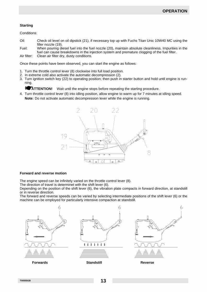
* The operator must never stand in the direction of descent (see chapter “safety instructions“).* The max. gradient of 25o must not be exceeded.
☛ATTENTION! A tilt in excess of this angle could lead to a stopping of the engine due to the automaticlow oil shut-off system. A restarting of the engine can only take place after the valve leverat the oil filter housing has been actuated once.
Right ! Wrong !
T00555GB 13
OPERATION
Starting
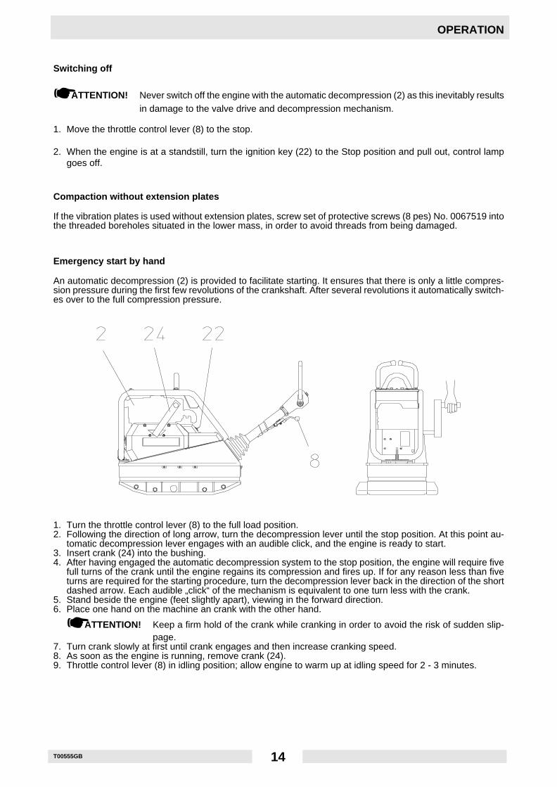
Conditions:
Oil: Check oil level on oil dipstick (21), if necessary top up with Fuchs Titan Unic 10W40 MC using thefiller nozzle (19).
Fuel: When pouring diesel fuel into the fuel nozzle (20), maintain absolute cleanliness. Impurities in thefuel can cause breakdowns in the injection system and premature clogging of the fuel filter.
Air filter: Clean air filter dry, dusty conditions.
Once these points have been observed, you can start the engine as follows:
1. Turn the throttle control lever (8) clockwise into full load position.2. In extreme cold also activate the automatic decompression (2).3. Turn ignition switch key (22) to operating position; then push in starter button and hold until engine is run-
ning.
☛ATTENTION! Wait until the engine stops before repeating the starting procedure.4. Turn throttle control lever (8) into idling position, allow engine to warm up for 7 minutes at idling speed.
Note: Do not activate automatic decompression lever while the engine is running.
Forward and reverse motion
The engine speed can be infinitely varied on the throttle control lever (8).The direction of travel is determinet with the shift lever (6).Depending on the position of the shift lever (6), the vibration plate compacts in forward direction, at standstillor in reverse direction.The forward and reverse speeds can be varied by selecting intermediate positions of the shift lever (6) or themachine can be employed for particularly intensive compaction at standstill.
Forwards Standstill Reverse
T00555GB 14
OPERATION
Switching off
☛ATTENTION! Never switch off the engine with the automatic decompression (2) as this inevitably resultsin damage to the valve drive and decompression mechanism.
1. Move the throttle control lever (8) to the stop.
2. When the engine is at a standstill, turn the ignition key (22) to the Stop position and pull out, control lampgoes off.
Compaction without extension plates
If the vibration plates is used without extension plates, screw set of protective screws (8 pes) No. 0067519 intothe threaded boreholes situated in the lower mass, in order to avoid threads from being damaged.
Emergency start by hand
An automatic decompression (2) is provided to facilitate starting. It ensures that there is only a little compres-sion pressure during the first few revolutions of the crankshaft. After several revolutions it automatically switch-es over to the full compression pressure.
1. Turn the throttle control lever (8) to the full load position.2. Following the direction of long arrow, turn the decompression lever until the stop position. At this point au-
tomatic decompression lever engages with an audible click, and the engine is ready to start.3. Insert crank (24) into the bushing.4. After having engaged the automatic decompression system to the stop position, the engine will require five
full turns of the crank until the engine regains its compression and fires up. If for any reason less than fiveturns are required for the starting procedure, turn the decompression lever back in the direction of the shortdashed arrow. Each audible „click“ of the mechanism is equivalent to one turn less with the crank.
5. Stand beside the engine (feet slightly apart), viewing in the forward direction.6. Place one hand on the machine an crank with the other hand.
☛ATTENTION! Keep a firm hold of the crank while cranking in order to avoid the risk of sudden slip-page.
7. Turn crank slowly at first until crank engages and then increase cranking speed.8. As soon as the engine is running, remove crank (24).9. Throttle control lever (8) in idling position; allow engine to warm up at idling speed for 2 - 3 minutes.
T00555GB 15
OPERATION
Mechanical oil pressure control
It is necessary to reactivate the mechanical oil pressure control in the following cases:- after the initial filling - first filling - of the fuel tank or if the tank has run dry.- in the case of an automatic engine stop due to an inefficient engine oil supply.- after freeing the engine when in presence of extremely low temperatures.
1. Fill up fuel tank.2. Check engine oil level.3. To activate depress hand lever „1“ for approx. 5 seconds.4. Hold down pin „1“ during approx. 5 seconds in the case of encapsulated engine versions.5. Simultaneously actuate hand lever a few times in the case of engines equipped with fuel pumps.6. Complete engine. Check to see that encapsulating elements seal correctly.
☛ATTENTION! Check oil level every 8 to 15 operating hours in spite of the mechanical oil pressure con-trol.
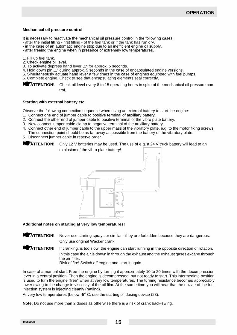
Starting with external battery etc.
Observe the following connection sequence when using an external battery to start the engine:1. Connect one end of jumper cable to positive terminal of auxiliary battery.2. Connect the other end of jumper cable to positive terminal of the vibro plate battery.3. Now connect jumper cable clamp to negative terminal of the auxiliary battery.4. Connect other end of jumper cable to the upper mass of the vibratory plate, e.g. to the motor fixing screws.
The connection point should be as far away as possible from the battery of the vibratory plate.5. Disconnect jumper cable in reserve order.
☛ATTENTION! Only 12 V batteries may be used. The use of e.g. a 24 V truck battery will lead to anexplosion of the vibro plate battery!
Additional notes on starting at very low temperatures!
☛ATTENTION! Never use starting sprays or similar - they are forbidden because they are dangerous.Only use original Wacker crank.
☛ATTENTION! If cranking, is too slow, the engine can start running in the opposite direction of rotation.In this case the air is drawn in through the exhaust and the exhaust gases excape throughthe air filter.Risk of fire! Switch off engine and start it again.
In case of a manual start: Free the engine by turning it approximately 10 to 20 times with the decompressionlever in a central position. Then the engine is decompressed, but not ready to start. This intermediate positionis used to turn the engine "free" when at very low temperatures. The turning resistance becomes appreciablylower owing to the change in viscosity of the oil film. At the same time you will hear that the nozzle of the fuelinjection system is injecting cleanly (rattling).At very low temperatures (below -5o C, use the starting oil dosing device (23).
Note: Do not use more than 2 doses as otherwise there is a risk of crank back-swing.
T00467GB 16
MAINTENANCE
Maintenance schedule
Component Maintenance work Maintenance interval
External hardware Check for tightness. approx. 8 hours afterinitial start-up
Drive engine First oil change and filter. 25 hours after initialValve clearance Cold engine: Check valve clearance, and adjust start-up
if necessary.Inlet valve 0,1 mm - outlet valve 0,2 mm.
Air filter Check dry type air filter - clean or replace filter dailycartridge if necessary (pay attention to themaintenance indication).
Drive engine Check oil level, if nec. top up oil.
Centre pole height Regrease. weeklysetting, transportlock
V-belt Check V-belt, if. nec. replace. monthlyProtective frame, Check attachment screws for tight fit.central lifting pointTow-bar head Check oil level, top up if necessary.
Drive engine Oil change, change oil filter. every 250 hKeep cooling fins free of dirt, clean dry.Retighten all accessible screw connections.
Exciter Oil change.Battery Check acid level, if nec. top up with distilled water.Valve clearance Cold engine: Check valve clearance, and adjust
if necessary.Inlet valve 0,1 mm - outlet valve 0,2 mm.
Fuel filter Change filter. every 500 h
T00467GB 17
MAINTENANCE
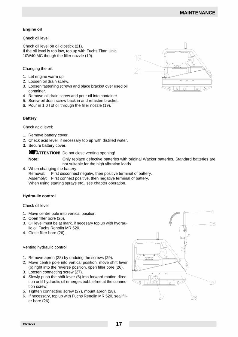
Engine oil
Check oil level:
Check oil level on oil dipstick (21).If the oil level is too low, top up with Fuchs Titan Unic10W40 MC though the filler nozzle (19).
Changing the oil:
1. Let engine warm up.2. Loosen oil drain screw.3. Loosen fastening screws and place bracket over used oil
container.4. Remove oil drain screw and pour oil into container.5. Screw oil drain screw back in and refasten bracket.6. Pour in 1,0 l of oil through the filler nozzle (19).
Battery
Check acid level:
1. Remove battery cover.2. Check acid level, if necessary top up with distilled water.3. Secure battery cover.
☛ATTENTION! Do not close venting opening!
Note: Only replace defective batteries with original Wacker batteries. Standard batteries arenot suitable for the high vibration loads.
4. When changing the battery:Removal: First disconnect negativ, then positive terminal of battery.Assembly: First connect positive, then negative terminal of battery.When using starting sprays etc., see chapter operation.
Hydraulic control
Check oil level:
1. Move centre pole into vertical position.2. Open filler bore (26).3. Oil level must be at mark, if necesary top up with hydrau-
lic oil Fuchs Renolin MR 520.4. Close filler bore (26).
Venting hydraulic control:
1. Remove apron (28) by undoing the screws (29).2. Move centre pole into vertical position, move shift lever
(6) right into the reverse position, open filler bore (26).3. Loosen connecting screw (27).4. Slowly push the shift lever (6) into forward motion direc-
tion until hydraulic oil emerges bubblefree at the connec-tion screw.
5. Tighten connecting screw (27), mount apron (28).6. If necessary, top up with Fuchs Renolin MR 520, seal fill-
er bore (26).
T00467GB 18
MAINTENANCE
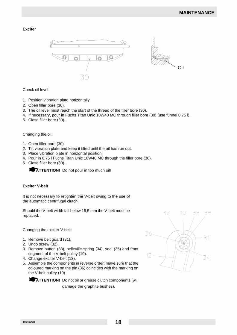
Exciter
Oil
Check oil level:
1. Position vibration plate horizontally.2. Open filler bore (30).3. The oil level must reach the start of the thread of the filler bore (30).4. If necessary, pour in Fuchs Titan Unic 10W40 MC through filler bore (30) (use funnel 0,75 l).5. Close filler bore (30).
Changing the oil:
1. Open filler bore (30).2. Tilt vibration plate and keep it tilted until the oil has run out.3. Place vibration plate in horizontal position.4. Pour in 0,75 l Fuchs Titan Unic 10W40 MC through the filler bore (30).5. Close filler bore (30).
☛ATTENTION! Do not pour in too much oil!
Exciter V-belt
It is not necessary to retighten the V-belt owing to the use ofthe automatic centrifugal clutch.
Should the V-belt width fall below 15,5 mm the V-belt must bereplaced.
Changing the exciter V-belt:
1. Remove belt guard (31).2. Undo screw (32).3. Remove button (33), belleville spring (34), seal (35) and front
segment of the V-belt pulley (10).4. Change exciter V-belt (12).5. Assemble the components in reverse order; make sure that the
coloured marking on the pin (36) coincides with the marking onthe V-belt pulley (10)
☛ATTENTION! Do not oil or grease clutch components (will
damage the graphite bushes).
T00556GB 19
FAULTS
Forward speed too low
Cause: - To little hydraulic oil in the centre pole head.- Air in hydraulic control.
Remedy: - Top up hydraulic oil.- Bleed system.
Reverse speed too low
Cause: - Too much oil in centre pole head.Remedy: - Correct oil level in accordance with mark.
No reverse motion
Cause: - Mechanical fault.Remedy: - Contact Wacker service dept.
Loss of hydraulic oil
Cause: - Leaks, hydraulic hose defective.Remedy: - Change defective parts.
Note: Bleed system after every dismantling operation.
Battery-charge warning lamp does not go off
Cause: - Dynamo defective.- Control unit defective.
Remedy: - Contact Wacker service dept.- Replace control unit (on rear of the dynamo).
Engine does not start
Cause: - Ignition lock defective.- Starter defective.- Start knop defective.- Battery flat.- Lack of lubricating oil.
Remedy: - Change defective parts.- Charge battery.- Fill up with oil and actuate valve lever at oil filter housing once.
E0127049GB-1 20
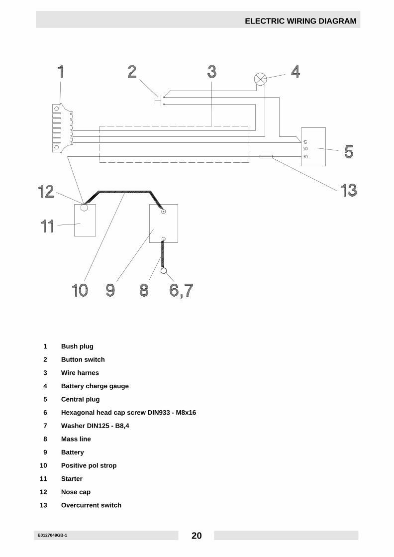
ELECTRIC WIRING DIAGRAM
1 Bush plug
2 Button switch
3 Wire harnes
4 Battery charge gauge
5 Central plug
6 Hexagonal head cap screw DIN933 - M8x16
7 Washer DIN125 - B8,4
8 Mass line
9 Battery
10 Positive pol strop
11 Starter
12 Nose cap
13 Overcurrent switch
C0000307.GB
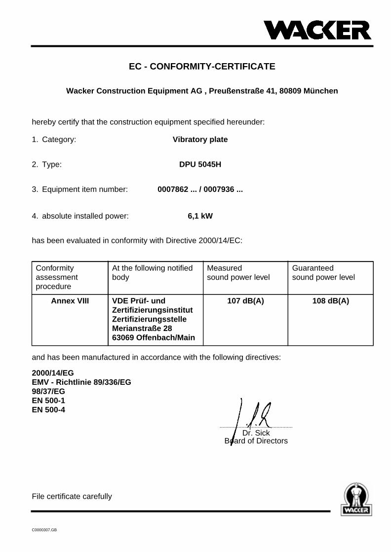
EC - CONFORMITY-CERTIFICATE
Wacker Construction Equipment AG , Preußenstraße 41, 80809 München
hereby certify that the construction equipment specified hereunder:
1. Category: Vibratory plate
2. Type: DPU 5045H
3. Equipment item number: 0007862 ... / 0007936 ...
4. absolute installed power: 6,1 kW
has been evaluated in conformity with Directive 2000/14/EC:
and has been manufactured in accordance with the following directives:
2000/14/EGEMV - Richtlinie 89/336/EG98/37/EGEN 500-1EN 500-4
..................................................
Dr. SickBoard of Directors
File certificate carefully
Conformityassessmentprocedure
At the following notifiedbody
Measuredsound power level
Guaranteedsound power level
Annex VIII VDE Prüf- undZertifizierungsinstitutZertifizierungsstelleMerianstraße 2863069 Offenbach/Main
107 dB(A) 108 dB(A)

22
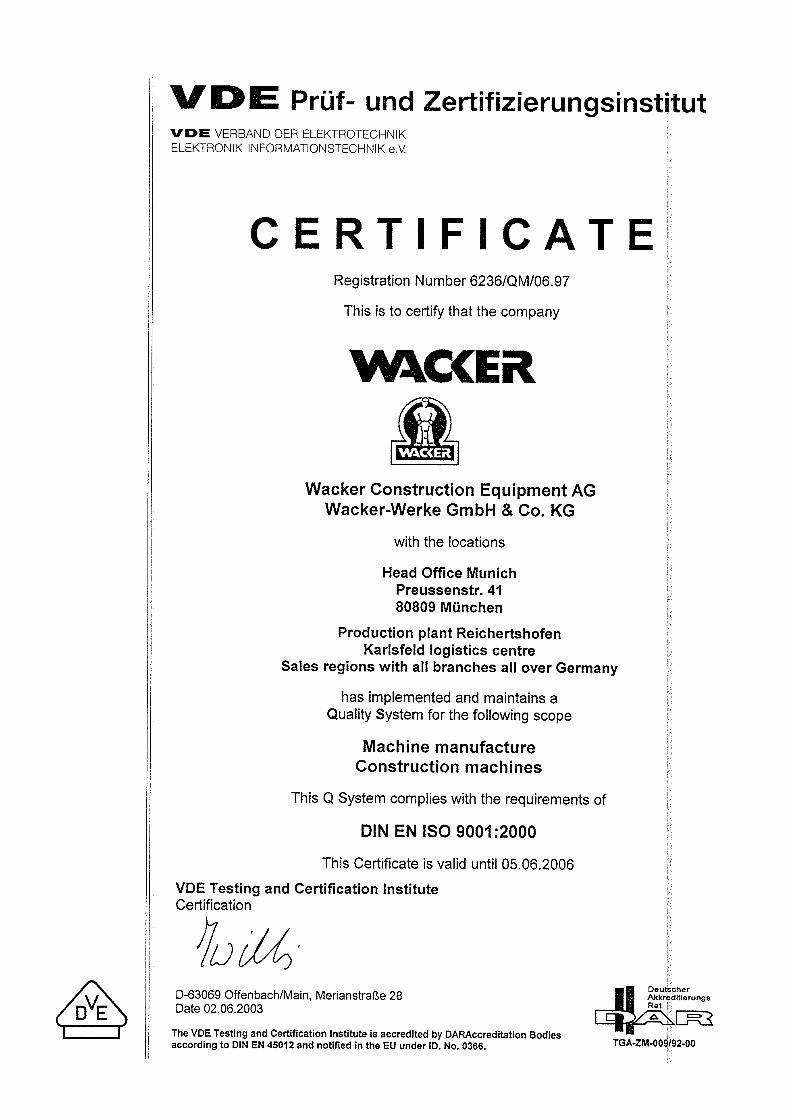
DIN EN ISO 9001 CERTIFICATE

Wacker Construction Equipment AG - Preußenstraße 41 - 80809 München - Tel.: +49-(0)89-3 54 02-0 - Fax: +49-(0)89-3 54 02-390Wacker Corporation - P.O. Box 9007 - Menomonee Falls, WI 53052-9007 - Tel.: +1-(1)(262)-255-0500 - Fax: +1-(1)(262)-255-0550 - Tel.: (800)770-0957Wacker Asia Pacific Operations-Skyline Tower, Suite 2303, 23/F, 39 Wang Kwong Road, Kowloon Bay, Hong Kong-Tel.: +852 2406 6032-Fax: +852 2406 6021


![Intelligence 4th edition - fisherlab.com · fisher intelligence [4th edition] 11.2004 #1 • unforgettable experiences pg. 1 #2 • id discrimination vs all-metal - pro’s & con’s](https://img.pdfslide.us/doc/110x75/5eb5d1e80c569a71332a8b2f/intelligence-4th-edition-fisher-intelligence-4th-edition-112004-1-a-unforgettable.jpg)