Embed Size (px)
Citation preview

Operator's manual
TruBend Series 7000


Operator's manual
TruBend Series 7000
Edition 2008-11-19

Order Information Please specify when ordering this document: Operator's manual TruBend Series 7000 Edition 2008-11-19 Document number B631EN
Address for orders TRUMPF Werkzeugmaschinen GmbH + Co. KG Technische Dokumentation Johann-Maus-Straße 2 D-71254 Ditzingen Fon: +49 7156 303 - 0 Fax: +49 7156 303 - 30540 Internet: http://www.trumpf.com E-Mail: [email protected]
This document was compiled by the Technical Documentation Dept. of TRUMPF Werkzeugmaschinen GmbH + Co. KG. All rights, in particular the right to reproduce, distribute or translate this docu-mentation, are reserved to TRUMPF Werkzeugmaschinen GmbH + Co. KG, even in case of patent and industrial rights applications. No part of this docu-mentation may be reproduced, processed, duplicated or distributed by means of electronic systems in any form whatsoever without the prior written consent of TRUMPF Werkzeugmaschinen GmbH + Co. KG Subject to errors and tech-nical changes. © TRUMPF Werkzeugmaschinen GmbH + Co. KG TRUMPF Werkzeugmaschinen GmbH + Co. KG cannot be held responsible for possible mistakes in this documentation. Any warranty for direct and indi-rect damages, arising in connection with the delivery or the use of this docu-mentation, is excluded, as far as this is in conformity with the law.

B631EN 2008-11-19 Table of contents 0-5
Table of contents
Chapter 1 Safety
Delivery versions ........................................................ 1-3
1. For your safety............................................................... 1-4
2. Operational safety ......................................................... 1-5 2.1 Authorized use................................................................. 1-5 2.2 Authorized personnel....................................................... 1-5
3. Hazards........................................................................... 1-6 3.1 Overview of laser classes ................................................ 1-6 3.2 Hazards due to laser radiation......................................... 1-6 3.3 Hazards when dealing with workpieces........................... 1-6
Upper and lower tool .................................................. 1-7 Workpieces ................................................................. 1-7 Side of the workpiece ................................................. 1-8 Position the workpiece................................................ 1-9
3.4 Dangers in the switch cabinet.......................................... 1-9 3.5 Noise hazards.................................................................. 1-9
4. Measures to be taken by the manufacturer .............. 1-10 4.1 Safety devices and protection of danger zones............. 1-10
Safety functions of the control system...................... 1-12 4.2 Signs on the machine .................................................... 1-14
5. Measures to be taken by the operator....................... 1-19 5.1 Observing warnings and danger signs .......................... 1-19 5.2 Instructing personnel ..................................................... 1-19 5.3 Adhering to the duty of care when handling the
machine ......................................................................... 1-19 5.4 Using spare parts, accessories and operating
material .......................................................................... 1-20
6. Overview of residual risks .......................................... 1-21
Chapter 2 TruBend Series 7000 installation conditions

0-6 Table of contents 2008-11-19 B631EN
Who does what?......................................................... 2-3
1. Planning aid ................................................................... 2-4
2. Installation site............................................................... 2-5 2.1 Arrangement and space requirements of the
machines.......................................................................... 2-5 2.2 Floor requirements........................................................... 2-5 2.3 Weight load...................................................................... 2-6 2.4 Ambient conditions .......................................................... 2-7
3. Electrical supply ............................................................ 2-8 3.1 Power supply ................................................................... 2-8
Isolating transformer................................................... 2-8 3.2 Connected loads, fuse protection, frequency .................. 2-9 3.3 Remote diagnostics ....................................................... 2-10 3.4 Network connection ....................................................... 2-11
4. Transport ...................................................................... 2-12 4.1 Preparations for transporting the machine to the
installation site ............................................................... 2-12 Preparing auxiliary tools ........................................... 2-12
4.2 Unloading machine and transporting it to installation site ............................................................... 2-13
Checking for damage in transit................................. 2-13 Unloading and transporting the machine.................. 2-13
Chapter 3 Description
1. Machine concept............................................................ 3-3
2. Technical data................................................................ 3-5
3. Machine axes ................................................................. 3-6
4. Modules of the machine................................................ 3-7 4.1 Nameplate and CE marking............................................. 3-8 4.2 Machine frame ................................................................. 3-8 4.3 Press table....................................................................... 3-8 4.4 Beam................................................................................ 3-9 4.5 Electromechanical direct drive and safety brake............. 3-9 4.6 Tool clamp ..................................................................... 3-10
Manual tool clamping................................................ 3-10

B631EN 2008-11-19 Table of contents 0-7
Centrally mechanical tool clamping (optional).......... 3-11 4.7 Backgauge..................................................................... 3-11
3-axis backgauge...................................................... 3-12 6-axis backgauge (optional) ..................................... 3-13
4.8 Control system............................................................... 3-13 Graphical shopfloor programming (optional) ............ 3-13 E-Shop...................................................................... 3-14 Help at the control system........................................ 3-14
4.9 Control panel ................................................................. 3-15 4.10 Foot switch..................................................................... 3-16 4.11 Safety device ................................................................. 3-17
Optoelectronic safety device: BendGuard with block laser................................................................. 3-17 Side safety doors...................................................... 3-18
4.12 Ergonomics.................................................................... 3-19 Comfort base plate (optional) ................................... 3-19 Standing and sitting aid (optional) ............................ 3-20 Comfort foot support (optional)................................. 3-20 Front iLED illumination (optional) ............................. 3-21 Rear iLED illumination (optional) .............................. 3-21
4.13 Line laser (optional). ...................................................... 3-22
5. Tools ............................................................................. 3-23 5.1 Tools from TRUMPF...................................................... 3-23
Chapter 4 Operation
1. Description of the operating elements ........................ 4-5 1.1 Foot switch....................................................................... 4-5 1.2 Control panel ................................................................... 4-6 1.3 User interface .................................................................. 4-7
User interface layout................................................... 4-7 1.4 Operating elements at the switch cabinet...................... 4-10
2. Operating modes ......................................................... 4-11
3. Switching on the machine .......................................... 4-12 3.1 Releasing emergency stop/Emergency shutdown ........ 4-12 3.2 Switching on the machine.............................................. 4-12
4. Switching off the machine .......................................... 4-14 4.1 Switching off the machine in the case of
malfunctions................................................................... 4-14

0-8 Table of contents 2008-11-19 B631EN
4.2 Switching off the machine.............................................. 4-14
5. Behavior in case of emergency and malfunctions ................................................................ 4-15
5.1 Rescuing trapped persons............................................. 4-15
6. Optoelectronic safety devices (optional) .................. 4-16 6.1 Activating the optoelectronic safety device.................... 4-16 6.2 Avoiding dirt ................................................................... 4-16 6.3 Checking the function of the BendGuard....................... 4-16 6.4 Check the light field of the BendGuard using block
laser ............................................................................... 4-17 6.5 Operating the machine without optoelectronic
safety devices ................................................................ 4-18
7. Manual operation ......................................................... 4-19 7.1 Defining the basic parameters....................................... 4-19 7.2 Defining other parameters ............................................. 4-20 7.3 Programming an increased working speed ................... 4-20 7.4 Conducting collision check ............................................ 4-21 7.5 Producing individual bendings....................................... 4-22 7.6 Using user defined bending characteristics................... 4-22
8. Programming ............................................................... 4-23 8.1 Creating programs numerically...................................... 4-23
Creating a program................................................... 4-23 8.2 Creating programs graphically (optional)....................... 4-24
Creating a program................................................... 4-25 Creating profile ......................................................... 4-26 Deleting profile.......................................................... 4-28 Modifying profile........................................................ 4-28 Creating development. ............................................. 4-29
8.3 Defining tool stations ..................................................... 4-30 Programming tool stations........................................ 4-30
8.4 Displaying bending process (3D)................................... 4-32 Simulating bending process ..................................... 4-33 Adjusting the bending process ................................. 4-34
8.5 Defining bendings .......................................................... 4-35 Programming bendings ............................................ 4-35 Programming an increased working speed .............. 4-36
8.6 Using user defined bending characteristics................... 4-37 Using separate bending characteristics ................... 4-37
8.7 Check............................................................................. 4-38 Running program check ........................................... 4-38
8.8 Loading a program......................................................... 4-38 Loading a program ................................................... 4-38

B631EN 2008-11-19 Table of contents 0-9
8.9 Managing programs....................................................... 4-40 Importing/exporting program .................................... 4-41 Deleting a program ................................................... 4-42 Renaming a program................................................ 4-43
9. Production.................................................................... 4-44 9.1 Loading a program......................................................... 4-44 9.2 Creating a production plan............................................. 4-45 9.3 Displaying setup plan..................................................... 4-46 9.4 Defining corrections ....................................................... 4-46 9.5 Setting the safety mode ................................................. 4-47 9.6 Producing bending parts................................................ 4-48 9.7 Display production data ................................................. 4-48
10. Technology................................................................... 4-49 10.1 Managing tools .............................................................. 4-49
Creating a new tool................................................... 4-49 Editing a tool ............................................................. 4-52 Importing a tool ......................................................... 4-53 Exporting a tool......................................................... 4-54 Deleting a tool........................................................... 4-54 Managing tool groups ............................................... 4-55
10.2 Managing materials and raw materials.......................... 4-55 Creating raw materials.............................................. 4-56 Editing raw materials ................................................ 4-56 Deleting raw materials .............................................. 4-57 Creating material ...................................................... 4-57 Editing material ......................................................... 4-57 Deleting material....................................................... 4-58
10.3 Managing bend allowances ........................................... 4-58 Creating bend allowance .......................................... 4-58 Editing bend allowance............................................. 4-59 Deleting bend allowance .......................................... 4-59 Importing bend allowances....................................... 4-60 Exporting bend allowances....................................... 4-60
10.4 Creating user defined bending characteristic ................ 4-61 Creating a separate bending characteristic.............. 4-61
10.5 E-Shop........................................................................... 4-63 Procuring bending tools and spare parts online ....... 4-63
10.6 Program parameters...................................................... 4-63 Modifying default values ........................................... 4-63 Switching the functions on and off............................ 4-64 Switching off collision check ..................................... 4-64
10.7 PDF viewer .................................................................... 4-64 Displaying files using the PDF viewer ...................... 4-64

0-10 Table of contents 2008-11-19 B631EN
11. Maintenance & start-up ............................................... 4-66 11.1 Isolating options............................................................. 4-66 11.2 Activating options........................................................... 4-66 11.3 User management ......................................................... 4-67
Defining a user.......................................................... 4-67 11.4 Managing bending programs......................................... 4-68
Defining directories for bending programs ............... 4-68 Defining the criterion for the management of bending programs (classification)............................. 4-69
12. Diagnostics .................................................................. 4-70 12.1 Displaying current messages......................................... 4-70 12.2 Displaying all messages ................................................ 4-70
13. Help ............................................................................... 4-72
Chapter 5 Setting work
1. Tools ............................................................................... 5-2 1.1 Loading tools with manual tool clamping......................... 5-2 1.2 Loading tools with centrally mechanical tool
clamping........................................................................... 5-2
2. Mute point....................................................................... 5-4 2.1 Defining the mute point.................................................... 5-4
3. Optoelectronic safety device........................................ 5-5 3.1 BendGuard with block laser............................................. 5-5
Aligning the light field.................................................. 5-5
Chapter 6 Maintenance
1. General guidelines......................................................... 6-3
2. Maintenance Overview .................................................. 6-4
3. Lubrication ..................................................................... 6-5 3.1 Overview.......................................................................... 6-5 3.2 Maintenance Instructions................................................. 6-7

B631EN 2008-11-19 Table of contents 0-11
Backgauge.................................................................. 6-7 Y axis on the beam..................................................... 6-9 Beam drive................................................................ 6-10 Slewable control panel (optional) ............................. 6-12
4. Mechanical elements................................................... 6-13 4.1 Overview........................................................................ 6-13 4.2 Maintenance Instructions............................................... 6-14
Switch cabinet........................................................... 6-14 Illumination................................................................ 6-17 Optoelectronic safety device .................................... 6-18 Safety brake.............................................................. 6-19 Foot support.............................................................. 6-21 Tool clamp ................................................................ 6-22
5. Electrics........................................................................ 6-23 5.1 Overview........................................................................ 6-23 5.2 Maintenance Instructions............................................... 6-24
Safety doors.............................................................. 6-24 Energy supply chain on the backgauge ................... 6-24 BendGuard with block laser...................................... 6-26
Chapter 7 Index

0-12 2008-11-19 B631EN

B631EN 2008-11-19 Safety 1-1
Chapter 1
Safety
Delivery versions ........................................................ 1-3
1. For your safety............................................................... 1-4
2. Operational safety ......................................................... 1-5 2.1 Authorized use................................................................. 1-5 2.2 Authorized personnel....................................................... 1-5
3. Hazards........................................................................... 1-6 3.1 Overview of laser classes ................................................ 1-6 3.2 Hazards due to laser radiation......................................... 1-6 3.3 Hazards when dealing with workpieces........................... 1-6
Upper and lower tool .................................................. 1-7 Workpieces ................................................................. 1-7 Side of the workpiece ................................................. 1-8 Position the workpiece................................................ 1-9
3.4 Dangers in the switch cabinet.......................................... 1-9 3.5 Noise hazards.................................................................. 1-9
4. Measures to be taken by the manufacturer .............. 1-10 4.1 Safety devices and protection of danger zones............. 1-10

1-2 Safety 2008-11-19 B631EN
Safety functions of the control system...................... 1-12 4.2 Signs on the machine .................................................... 1-14
5. Measures to be taken by the operator....................... 1-19 5.1 Observing warnings and danger signs .......................... 1-19 5.2 Instructing personnel ..................................................... 1-19 5.3 Adhering to the duty of care when handling the
machine ......................................................................... 1-19 5.4 Using spare parts, accessories and operating
material .......................................................................... 1-20
6. Overview of residual risks .......................................... 1-21

B631EN 2008-11-19 For your safety 1-3
Delivery versions
Machines with complete safety equipment according to the re-quirements of the EC Machinery Directive: • These machines are supplied with CE marking as well as EC
Declaration of Conformity.
Machines without complete safety equipment: • These machines do not fulfill all requirements of the EC Ma-
chinery Directive. These are supplied with an EC Manufac-turer's Declaration and without CE marking. – Machines without complete safety equipment do not have
the optoelectronic safety device, operate with the maxi-mum closing speed of the beam and the maximum posi-tioning speed of the backgauge.
• The operator must take suitable measures for the operational safety of the machine in accordance with the statutory regula-tions of the country in which it is operated.
• Machines without complete safety equipment cannot be oper-ated in the European Union and its associated countries.
Note The machine with complete safety equipment is described in the operator's manual.

1-4 For your safety 2008-11-19 B631EN
1. For your safety
With the CE marking and the EC Declaration of Conformity, TRUMPF confirms that the machine corresponds to the basic sa-fety and health-related requirements of the EC Machinery Direc-tive, ANSI and OSHA.
The CE marking is located on the nameplate of the machine. The EC Declaration of Conformity is delivered along with the machine.
This chapter describes the safety concept of the machine and in-dicate possible dangers and measures. The overview of residual risks contains measures to be taken by the operator in order to reduce the residual risks.
Note The operator must adhere to the valid safety and accident preven-tion regulations of the respective country and the safety laws of the state and of the region!
Certain activities can be a source of danger during the operation. The documentation contains warnings before the instructions for these activities. Danger signs are attached on the machine (see "Measures to be taken by the manufacturer", pg. 1-10).
A warning contains signaling words that have been explained in the following table:
Signaling word Description
Danger Indicates a major danger. Could lead to death and seri-ous injuries if not avoided.
Warning Refers to a dangerous situation. Could lead to serious injuries if not avoided.
Caution Refers to a dangerous situation. Could lead to injuries if not avoided.
Example:
Danger
Suspended load! Falling loads could lead to severe injuries or even death.
Observe the safety regulations for the handling of heavy lo-ads.
Never walk under a suspended load. Use tested and appropriately sized tackle and means of
transportation. Employ qualified technicians to transport the machine. Carry out the transport in accordance with the transport re-
gulations.
EC Declaration of Conformity
Chapter Safety
Warnings and danger signs
Tab. 1-1

B631EN 2008-11-19 Operational safety 1-5
2. Operational safety
The machine can become a source of danger if it is used inappro-priately or for purposes other than intended (see "Overview of re-sidual risks", pg. 1-21): • Dangers to the safety of the operator. • Damage to the machine and to other objects of the operator. • Impairment of the working efficiency of the machine. 2.1 Authorized use
The operator may only bend cold metal sheets using the machine.
The operator may use the machine only in the industrial sector.
The installation, operation and transport conditions for the machine prescribed by TRUMPF must be adhered to and the maintenance work must be performed. The installation of the machine and its operation must comply with the national regulations valid in the country where the machine is operated. The operator must adhere to the national regulations.
The following is impermissible: • Unauthorized changes and retrofitting of the machine. • Any working procedure that impairs the safety. • Processing of hot or splintering materials. • Unauthorized use of tools that are not allowed by TRUMPF.
Any use, service and maintenance going beyond this is not in-tended. TRUMPF does not accept liability for any damage to prop-erty or persons arising from these. The risk is borne solely by the operator. The machine guarantee will be voided. 2.2 Authorized personnel
Only authorized, trained and briefed personnel should operate, set and service the machine.
Only specially trained personnel should: • work on the electrical modules. • Transporting, installing, and disassembling the machine. • Check safety elements.
Machine
Exemption from liability

1-6 Hazards 2008-11-19 B631EN
3. Hazards
3.1 Overview of laser classes
Laser systems are divided into laser classes according to the Eu-ropean standard EN 60825-1. The laser class corresponds to the hazard level of the laser light emitted.
Laser class Description
1 The accessible laser radiation is not dangerous under sensibly predictable conditions.
2M The accessible laser radiation lies in the visible spectral range of 400 nm to 700 nm. It is not dangerous for eyes in the case of short exposure time (up to 0.25 s) as long as the beam is not observed through optical instruments (magnifying glass, lens, telescope). Eyes are normally protected from the laser light by turning away and closing the eyelids.
Overview of laser classes 3.2 Hazards due to laser radiation
BendGuard with block laser is an optoelectronic safety device and corresponds to laser class 1.
Warning
Class 1 laser radiation! Eye injury.
Do not look directly into the laser beam.
The line laser corresponds to the laser class 2M.
Warning
Class 2M laser radiation! Long-term damage to eyes.
Do not look directly into the laser beam. Do not look at the laser beam directly through optical instru-
ments. 3.3 Hazards when dealing with workpieces
Handling of workpieces can be a source of danger. These dangers and the measures taken against them differ depending on the workpiece.
Tab. 1-2
BendGuard with block laser
Line laser

B631EN 2008-11-19 Hazards 1-7
Upper and lower tool
Warning
Beam moves downwards! Separation of body parts.
Never insert hands between upper and lower tools.
Workpieces
Warning
Workpieces have sharp edges! Risk of injury
Wear personal protective gear.
Warning
Workpieces falling due to sudden release of the beam! Risk of injury
Wear personal protective gear. Select a lower tool die width that is suitable for the material
thickness of the workpiece and angle.
Fig. 25903
1-8 Hazards 2008-11-19 B631EN
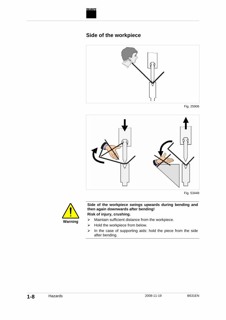
Side of the workpiece
Warning
Side of the workpiece swings upwards during bending and then again downwards after bending! Risk of injury, crushing.
Maintain sufficient distance from the workpiece. Hold the workpiece from below. In the case of supporting aids: hold the piece from the side
after bending.
Fig. 25906
Fig. 53449

B631EN 2008-11-19 Hazards 1-9
Position the workpiece
The workpiece and the gauge fingers of the backgauge can collide if the workpiece is positioned incorrectly.
Depending on the processing strategy of the backgauge, the work-piece must be positioned such that it does not collide with the backgauge.
Warning
Backgauge moves unexpectedly! Risk of injury
Position the workpiece only after the backgauge has moved to the next position.
3.4 Dangers in the switch cabinet
Danger
Electrical voltage! Electric shock.
Keep the switch cabinet closed. Each time before opening the switch cabinet: set the MAIN
SWITCH to 0 and wait for five minutes.
Caution
Hot surface! Burns.
Keep the switch cabinet closed. Each time before opening the switch cabinet: set the MAIN
SWITCH to 0 and wait for the cooling phase. 3.5 Noise hazards
The A-rated equivalent continuous sound pressure level at the workstation of the operating personnel is ≤70 dB(A).

1-10 Measures to be taken by the manufacturer 2008-11-19 B631EN
4. Measures to be taken by the manufacturer
The danger zone of the machine is safeguarded by safety devices. The machine may only be operated with these safety devices. 4.1 Safety devices and protection of
danger zones
Danger zones of the machine are protected by safety devices.
1 Safety brake 6 Upper protective cover 2 Rear protective cover 7 Emergency stop impact button 3 Main switch and Service key
switch 8 Beam down foot switch with stop
function 4 Optoelectronic safety device
(optional) 9 Emergency-up foot switch
5 Side safety doors
Safety devices and danger zones
Fig. 53816

B631EN 2008-11-19 Measures to be taken by the manufacturer 1-11
EMERGENCY STOP brings about the following: • The power supply to the machine is disconnected (24 V control
voltage is maintained). • The axes motion stops. • The safety brake is activated. • EMERGENCY-UP is deactivated.
The BEAM DOWN foot switch has three positions:
Position Description 0 Not pressed The beam stands still or stops.
1 Pressed The beam moves downwards.
2 Pushed through The axes motion stops. The safety brake is activated.
The EMERGENCY-UP foot switch can be used to move the beam upwards. The EMERGENCY-UP foot switch is not active if EMERGENCY STOP was triggered. The EMERGENCY-UP foot switch has two positions:
Position Description 0 Not pressed No effect on the beam.
1 Pressed The beam moves upwards. The control system remains set to START.
The optoelectronic safety device monitors the area below the up-per tool during a light field operation.
The beam moves at the maximum speed (up to 220 mm/s) be-tween the upper dead point and the mute point The optoelectronic safety device monitors the area in front of and below the upper tool. If the light field is interrupted during operation, the beam stops moving.
The beam moves at a reduced speed between the mute point and the lower dead point. The optoelectronic safety device monitors the area below the tool tip of the upper tool. If the light field is inter-rupted during operation, the beam stops moving.
The side safety doors secure the area to the side of the beam and the press table. When the safety doors are closed, the danger zo-ne cannot be accessed from the side.
If both the side safety doors are opened during operation: • The axes motion stops. • The safety brake is activated.
Emergency stop impact but-ton
Beam down foot switch with stop function
Tab. 1-3
Emergency-up foot switch
Tab. 1-4
Optoelectronic safety device (optional)
Side safety doors

1-12 Measures to be taken by the manufacturer 2008-11-19 B631EN
If one of the side safety doors is opened during operation: • The axes motion stops. • The opening can be confirmed with the Beam down foot
switch. All axes can again be moved. The beam moves only at a reduced speed.
The rear protective cover secures the danger zone inside the ma-chine. The protective cover is firmly screwed.
The rear protective cover must be firmly screwed each time after being removed.
The upper protective cover secures the commuting area of the sa-fety brake. The protective cover is firmly screwed.
The upper protective cover must be firmly screwed each time after being removed.
If the beam does not stop within the springback and the lag time, the safety brake stops the machine drive. The beam movement stops.
The safety brake locks the drive at standstill and prevents the beam from falling.
The main switch is used to switch the machine on or off. The main switch can be prevented from being switched on again using a lock.
There is a key switch for the maintenance work performed by trai-ned personnel.
The key switch is located on the switch cabinet and has two posi-tions.
0 The machine is switched off when the switch cabinet doors are opened.
1 The power supply of the machine is maintained when the switch cabinet doors are opened.
Safety functions of the control system
The danger zones of the machine are additionally protected by the safety functions of the control system.
The machine is equipped with a safety control system that corre-sponds to the requirements of the EN 954-1 category 4.
Rear protective cover
Upper protective cover
Safety brake
Main switch
Key switch for service (only in USA and Canada)
Tab. 1-5
Safety control system

B631EN 2008-11-19 Measures to be taken by the manufacturer 1-13
This means: even if there is an error in the control system, all sa-fety devices and safety measures continue working.
Individual bends of a program can be programmed with an in-creased working speed (up to 25 mm/s).
The working speed of the beam is monitored and can be more than 10 mm/s only under the following prerequisites: • A tool with a permissible die width is selected. • The bending angle is 90°. • The correction of the bending angle is smaller than or equal to
10°. • BendGuard Mode 1, 2, 3 or 4 is selected.
The backgauge can move upwards and downwards (R axis), for-wards and backwards (X axis) and to right and left (Z axis) in a CNC-controlled manner. The axes are controlled through the ma-chine control system.
In order to avoid collisions and crushing, the backgauge drive is run in the X direction with the force restricted to 150 N. If the gauge finger runs into an obstacle in the X direction, the backgauge stops. The axes can move freely.
The line laser projects a line on the sheet in order to indicate the bending line.
During the bending process, the line laser is automatically switched off when the beam moves down from the clamping point. This pre-vents laser reflections during the bending process.
If the beam is at the upper dead point for longer than five minutes, the line laser is automatically switched off.
The BendGuard with block laser is installed such that it can be rai-sed by 25 mm. If the BendGuard with block laser is raised due to an obstacle (e.g. trapped hand) during the bending process, the beam stops.
Bending tools are clamped by a central, mechanical tool clamp (optional). The tool clamping is opened and closed by a detachable lever. The beam cannot be moved as long as the lever of the upper tool clamp is attached.
Monitoring the programmed working speed
Processing strategy of the backgauge
Monitoring of the line laser
Monitoring of the BendGuard block laser
Monitoring of the centrally mechanical upper tool clamp
(optional)

1-14 Measures to be taken by the manufacturer 2008-11-19 B631EN
4.2 Signs on the machine
Informative and danger signs indicate dangers when operating the machine.
1 Machine frame 4 BendGuard 6 Beam down foot switch 2 Line laser 5 Side safety doors 7 Emergency-up foot switch 3 Beam
Position of the signs
Sign no. Informative and danger signs
3
Risk of crushing between upper and lower tool
Fig. 54409

B631EN 2008-11-19 Measures to be taken by the manufacturer 1-15
Sign no. Informative and danger signs
3
Refer to the operator's manual. Safety information for the case of body parts getting trapped(see "Operation_Behavior in emergency").
1
Risk of crushing and risk of injury in the commuting area of the brake discs of the safety brake.
6 Marking for the beam down foot switch with stop function
7 Marking for the emergency-up foot switch
2, 4
Danger from class 2M laser radiation
Additional signage in the USA:

1-16 Measures to be taken by the manufacturer 2008-11-19 B631EN
Sign no. Informative and danger signs
5
Dangers when operating the machine
5
Marking for the danger zone
3
Risk of crushing between upper and lower tool

B631EN 2008-11-19 Measures to be taken by the manufacturer 1-17
Sign no. Informative and danger signs
5
Note: machine is top-heavy
5
Safety information

1-18 Measures to be taken by the manufacturer 2008-11-19 B631EN
Sign no. Informative and danger signs
5
Notes for avoiding injuries
Informative and danger signs on the machine
Tab. 1-6

B631EN 2008-11-19 Measures to be taken by the operator 1-19
5. Measures to be taken by the operator
5.1 Observing warnings and danger signs
Certain activities can be a source of danger during the operation. The documentation contains warnings before the instructions for these activities and danger signs are provided on the machine(see "Measures to be taken by the manufacturer", pg. 1-10). 5.2 Instructing personnel
The operator must take the following measures before the per-sonnel start working on the machine: • Informing the personnel about potential dangers. • If necessary, ensuring that the personnel wears personal pro-
tective gear. • Defining responsibilties for safety, operation, maintenance,
setting work and service. • Ensuring that the personnel read the technical documentation
of the machine. Recommendation: getting written confirmation for instructing the personnel.
Additional measures: • Ensuring that nobody wears long and loose clothes. • Reporting necessary repairs to the operator. 5.3 Adhering to the duty of care when
handling the machine
The operator must always make sure that nobody is within the danger zone before starting up the machine.
The operator should operate the machine only with safety devices. Safety devices should not be disassembled or switched off except during maintenance or service work. After completing this work, the operator must install the safety devices and switch them on.
Additional safety measures must be taken in order to process spe-cial parts that cannot be processed using the available safety de-vices.
All safety devices must be regularly checked for proper function.
Checking the danger zone and safety devices

1-20 Measures to be taken by the operator 2008-11-19 B631EN
Operator: • The operator or the persons appointed by him/her must oper-
ate the machine when it is in perfect working order. • The operator must meet the conditions specified in the installa-
tion plan and the installation conditions. • The operator must ensure that the work station is kept clean
and tidy by issuing appropriate instructions and conducting in-spections.
Operator: • The operator must report the changes (including the operating
performance) arising in the machine immediately to the owner. The machine must be checked for visible defects and damage at least once per shift.
The described shutdown procedures must be observed for all tasks. 5.4 Using spare parts, accessories and
operating material
Spare parts and accessories that are not approved by TRUMPF are not checked. Installing and using external parts and accesso-ries can change design-related properties of the machine and weaken the safety.
TRUMPF does not accept liability for damage arising from the use of external parts and accessories or improper installation or re-placement of original spare parts and accessories.
Ensure that the machine is in perfect working order
Observance of shutdown procedures
Using spare parts and ac-cessories
Exemption from liability

B631EN 2008-11-19 Overview of residual risks 1-21
6. Overview of residual risks
The machine has residual risks in spite of its safety devices, con-ception and construction type .
The following overview of residual risks shows the main potential hazards to life and health posed by the machine.
The measures that can be taken by the machine operator to re-duce the residual risks are specified in the overview.
Residual risk Dangerous point Type of danger Measure to be taken by the operator
Mechanical elements
Crushing and shearing
Entering into the danger zone Entering into the danger zone from the side
Risk of fatal injury
Operation by trained and in-structed personnel. Wear personal protective gear. If body parts are trapped: press the EMERGENCY-UP foot switch.
Crushing and shearing Defective safety brake Risk of fatal injury None
Gripping or re-tracting Crushing and shearing
Movement of the backgauge and the workpiece. Collision between the gauge fingers and the tool.
Risk of injury
Operation by trained and in-structed personnel. Select appropriate processing strategy of the backgauge.
Gripping or retracting Crushing
Movement of the brake disc Risk of injury
Specially trained personnel for maintenance, service and repairs. Screw the upper protective cover firmly.
Crushing Lock rod of the tool clamp Risk of injury Operation by trained and in-structed personnel.
Crushing Between the workpiece and the beam Risk of fatal injury Operation by trained and in-structed personnel.
Workpieces fal-ling
Releasing of the workpiece after bending Risk of injury
Operation by trained and in-structed personnel. Wear personal protective gear.
Instability Overturning of the machine Risk of fatal injury Use the provided lifting holes when transporting the machine.
Electrics
Electrical contact Direct contact with normally live parts. Risk of fatal injury Specially trained personnel for maintenance, service and repairs.
Indirect contact with parts that are live due to an error. Risk of fatal injury Specially trained personnel for
maintenance, service and repairs.
Thermal
Burns Hot surface of the brake Risk of injury Specially trained personnel for maintenance, service and repairs. Wait for the cooling phase
Residual risks
Tab. 1-7

1-22 Overview of residual risks 2008-11-19 B631EN

B631EN 2008-11-19 TruBend Series 7000 installation conditions - Version 0
2-1
Chapter 2
TruBend Series 7000 installation conditions
Material number 0383471

2-2 TruBend Series 7000 installation conditions - Version 0
2008-11-19 B631EN
Who does what?......................................................... 2-3
1. Planning aid ................................................................... 2-4
2. Installation site............................................................... 2-5 2.1 Arrangement and space requirements of the
machines.......................................................................... 2-5 2.2 Floor requirements........................................................... 2-5 2.3 Weight load...................................................................... 2-6 2.4 Ambient conditions .......................................................... 2-7
3. Electrical supply ............................................................ 2-8 3.1 Power supply ................................................................... 2-8
Isolating transformer................................................... 2-8 3.2 Connected loads, fuse protection, frequency .................. 2-9 3.3 Remote diagnostics ....................................................... 2-10 3.4 Network connection ....................................................... 2-11
4. Transport ...................................................................... 2-12 4.1 Preparations for transporting the machine to the
installation site ............................................................... 2-12 Preparing auxiliary tools ........................................... 2-12
4.2 Unloading machine and transporting it to installation site ............................................................... 2-13
Checking for damage in transit................................. 2-13 Unloading and transporting the machine.................. 2-13

B631EN 2008-11-19 Planning aid - Version 0 2-3
Who does what?
Before the machine is delivered, you must make sure that all of the conditions described in this chapter have been fulfilled.
If this is not the case, the TRUMPF Service personnel will not be able to put the system into service.
Note The MAIN SWITCH on the machine may only be switched on by TRUMPF Service personnel.
The machine is put into service by TRUMPF Service technicians.
This includes: • Installing, aligning, leveling and fastening the machine. • Connecting the machine to the supplies (with the exception of
the electrical power supply). • Performing a functional test. • Instructing personnel.
Customer
TRUMPF Service personnel

2-4 Planning aid - Version 0 2008-11-19 B631EN
1. Planning aid
The planning aid provides an overview of the measures to be taken and preparations to be carried out.
For details, refer to the corresponding sections of these installation conditions.
Time before the de-livery of the ma-chine
Planning criterion Measures Done/Date
Operator and training
• Appoint a member of staff to be responsible for preparations for the delivery of the machine.
• Select operating personnel, maintenance person-nel, and programmers. Set dates for training cour-ses.
Installation site
• Define the machine location. Consider the space requirements specified in the installation plan.
• Check the floor requirements (floor quality, even-ness). Observe the weight and dimensions of the machine here.
• Check the ambient conditions required (room tem-perature, exposure to sunlight, ambient air purity).
• Check the transport route (gateway dimensions, header heights, cable rack heights, room to ma-neuver around corners etc.).
Electrical supply
• Install electrical connections at the installation site. • Conductor cross-sections and fuses protection
according to legal requirements.
Telephone connection
Install an analog telephone connection.
8 weeks
Bending tools Order the initial bending tool equipment. Support from relevant TRUMPF department.
3 weeks but not later than week ....
Transport
Prepare necessary transport aids.
2-3 weeks, but not later than week ... Feedback Feedback to the relevant TRUMPF department that the
installation conditions have been fulfilled. During installation and start-up
Allocate qualified electricians Connect the system to the electrical power supply.
Tab. 2-1

B631EN 2008-11-19 Installation site - Version 0 2-5
2. Installation site
2.1 Arrangement and space requirements of the machines
The arrangement of the machines and the space requirements for standard installation can be taken from the applicable installation plan: • Arrangement of individual options. • Space requirements for opening all doors. • Outside dimensions of the protective cover and space re-
quirements for the protective cover when it is opened. • Electric power supply. • Telephone socket. 2.2 Floor requirements
Note If the requirements described below are not met, a structural ana-lyst must carry out an evaluation. Further data and information on floor requirements can be obtained from TRUMPF Maschinen Austria GmbH + Co. KG.
• The floor should be as even as possible. • An evenness deviation of 12 mm/10 meters (0.472 in/ 393.7 in)
is required (DIN 18202) in the area of the machine installation location.
Quality of the entire installation surface for the machine with switch cabinet: • Base plate throughout the area of the load-bearing points. • The floor must be oil-proof.
Pay attention to variable loads in the immediate vicinity of the ma-chines (e.g. forklifts, assembly and disassembly of machines di-rectly beside the press brake, shuttle carts, etc.).
• Carrying capacity of the subsurface at least ks = 5000 kN/m3. • Minimum thickness: 200 mm/7.87 in. • The reinforcement of the base plate should be at least equal to
or better than that specified in the tables below. • Concrete quality (corresponding to tensile strength C 25/30):
Evenness of the installation surface
Installation surface
Flexible base plate
2-6 Installation site - Version 0 2008-11-19 B631EN
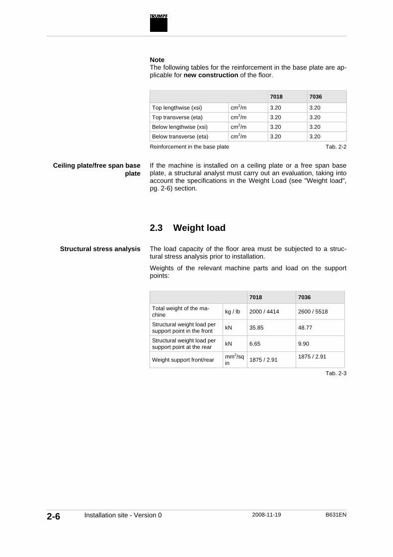
Note The following tables for the reinforcement in the base plate are ap-plicable for new construction of the floor.
7018 7036
Top lengthwise (xsi) cm2/m 3.20 3.20
Top transverse (eta) cm2/m 3.20 3.20
Below lengthwise (xsi) cm2/m 3.20 3.20
Below transverse (eta) cm2/m 3.20 3.20
Reinforcement in the base plate
If the machine is installed on a ceiling plate or a free span base plate, a structural analyst must carry out an evaluation, taking into account the specifications in the Weight Load (see "Weight load", pg. 2-6) section. 2.3 Weight load
The load capacity of the floor area must be subjected to a struc-tural stress analysis prior to installation.
Weights of the relevant machine parts and load on the support points:
7018 7036
Total weight of the ma-chine kg / lb 2000 / 4414 2600 / 5518
Structural weight load per support point in the front kN 35.85 48.77
Structural weight load per support point at the rear kN 6.65 9.90
Weight support front/rear mm2/sq in 1875 / 2.91 1875 / 2.91
Tab. 2-2
Ceiling plate/free span base plate
Structural stress analysis
Tab. 2-3

B631EN 2008-11-19 Installation site - Version 0 2-7
2.4 Ambient conditions
Permissible ambient temperature for machine operation: • +10°C/+50°F to +40°C/+104°F. • According to NFPA 79, the maximum temperature in the USA
and Canada is 40°C/104°F.
Permissible temperature range for the control system during transport or when the machine is switched off: • -20°C/-4°F to +70°C/+158°F.
Permissible humidity for the control system: • 10 to 95 % relative humidity, but non-condensing.
Machine ambient temperature
Ambient conditions for the control system

2-8 Electrical supply - Version 0 2008-11-19 B631EN
3. Electrical supply
3.1 Power supply
Continuous undervoltage or overvoltage is not permitted. Greater voltage fluctuations endanger the problem-free operation of the machines and reduce their performance.
Note The NEC is applicable only for USA and Canada!
The machine and the power distributor system must be equipped with a grounding line in accordance with NEC article 250, "Groun-ding".
For further details on grounding power distributor systems and in-dustrial plants, refer to the NEC standards or consult an electrician or the power station.
Power supply lines in ungrounded power supply systems with delta connection are not fail-safe by nature. Delta power supply systems tend to generate transient overvoltages to ground. Delta power supply systems can result in increased voltages being applied to the connected devices. The control system or the machine can no longer be reliably operated if a potential to ground develops in the system. For this reason, a grounded transformer must be installed in the star connection in delta power supply systems (see NEC article 450-5). Isolating transformer
The following notes must be observed if the machine is equipped with an isolating transformer: • The cable from the isolating transformer to the switch cabinet
of the machine must be provided and laid by the customer. • The isolating transformer is not indicated on the installation
plan. The customer must define the location of the isolating transformer.
• The isolating transformer must be installed such that access via the front door (door with nameplate) remains free. The re-quired safety distance is 800 mm according to IEC and 1100 mm according to NEC. A safety distance of 100 mm must be maintained behind and at the sides of the transformer.
NEC conditions
Grounding
Grounded power supply sys-tem with star connection

B631EN 2008-11-19 Electrical supply - Version 0 2-9
1 Isolating transformer 3 Lateral and rear safety distance 2 Front safety distance
3.2 Connected loads, fuse protection,
frequency
Machines should only be connected by qualified specialists.
Before shipping, the system is set to the power supply voltage and power frequency specified by the customer.
TruBend 7018 7036 Line voltage range VAC 360 - 480 360 - 480
Frequency tolerance - ±2 % ±2 %
Connected load kVA 5 6
Fuse protection at 400 V or 460 V A 3 x 35 3 x 35
Maximum interruption time - 10 ms every 10 s
Fig. 53198
Connected loads
Tab. 2-4

2-10 Electrical supply - Version 0 2008-11-19 B631EN
Regulation: Establish the electric power supply in accordance with DIN EN 60204-1/4.3.1:
Cable
Regulation • Four-pole copper cable (L1, L2, L3, PE). • Single strand or multi strand with wire end fer-
rules. • Connection must be protected against direct
contact. • Clockwise phase rotation.
Cable cross-section
Design in accordance with: VDE 0100, Part 430 (IEC 364-4-47) At least 6 mm2
Ground wire
Design in accordance with: VDE 0100, Part 540 (IEC 364-5-54) At least 6 mm2
Fault current circuit breaker
Recommendation: ABB: F204 B63 / 0,3 or DOEBKE: 4B SK 63-4 / 0,3
Note The NEC applies only to Canada and the USA.
• A four-pole connection is required: L1, L2, L3 and PE. • THHN copper or equivalent is recommended (2000 V maxi-
mum output) designed for a maximum temperature 90°C/194°F.
• No aluminum cables should be used to connect the machine. • The conductor cross-section must correspond to NEC 670-4
(a), with a permissible amperage of at least 125 % of the oper-ating current specified on the nameplate.
• To ensure the voltage stability and rating, the line should be larger than specified in the NEC table 310-16.
3.3 Remote diagnostics
A country-specific telephone interface is normally installed in the machine's switch cabinet for the installation of the Teleservice.
Note The connection point is indicated on the installation plan using this symbol.
Connecting cables
Tab. 2-5
NEC conditions

B631EN 2008-11-19 Electrical supply - Version 0 2-11
The following tasks must be initiated at the customer location: • Installation of a telephone socket for an analog modem at the
machine switch cabinet by the customer's telephone company. • It must be possible to access the modem with a direct dialing
number. Otherwise, a separate exchange line is required. 3.4 Network connection
TRUMPF provides the following interfaces for the network (e.g. a connection to a programming system) in the control cabinet of the machine: • RJ 45 plugs for customers with shielded-twisted pair network
cabling.
Telephone modem connec-tion

2-12 Transport - Version 0 2008-11-19 B631EN
4. Transport
4.1 Preparations for transporting the machine to the installation site
The customer must make the necessary arrangements to transport the machines from the truck to the final installation site.
Clarify the transport route to the machine installation site in a timely manner before its delivery. Check the following when doing so: • Gateway openings • Header heights. • Cable rack heights. • And similar.
Take into account the dimensions of the machine in accordance with the installation plan during transport.
TruBend 7018 7036 Weight kg / lb 2000 / 4414 2600 / 5732
Width mm/in 1290 / 51 1805 / 71
Depth max transport measurement T' mm/in 1255 / 49.4 1255 / 49.4
Height mm/in 2375 / 93.5 2375 / 93.5
Preparing auxiliary tools
Means, Tools, Materials • Crane truck for unloading the truck (carrying capacity corre-
sponding to the weight of the machine). • Fork lift for transporting the machine (carrying capacity min 3.5
t). or • Gantry crane for transporting the machine (carrying capacity
corresponding to the weight of the machine).
Prepare auxiliary transportation equipment three weeks prior to machine delivery. The auxiliary transportation equipment must be available dur-ing the entire installation process.
Dimensions and weight of the machines
Tab. 2-6

B631EN 2008-11-19 Transport - Version 0 2-13
4.2 Unloading machine and transporting it to installation site
Warning
The center of gravity of the machine is too far. The machine can easily tip over.
Use the lifting holes for the transport and installation of the machine.
Checking for damage in transit
1. Check all machine parts after delivery for damage caused dur-ing transit.
2. Record visible damage caused during transport on the cargo note and have the record countersigned by the truck driver.
3. Report any hidden damage caused during transport to the in-surance company and to TRUMPF within 6 days.
Unloading and transporting the machine
Means, Tools, Materials • When transporting the machine with a crane: type A shackle
(DIN 82101).
When transporting the machine with a crane: use two type A shackles per machine (DIN 82101):

2-14 Transport - Version 0 2008-11-19 B631EN
TruBend 7018 / 7036 Permissible loading kN 94
Bolt diameter 1 3/8"
d1 30 / 1.181
d4 36 / 1.417
h1 111 / 4.370 Main dimensions mm/in
b1 47 / 1.850
Technical data for the shackles for different machine types
Fig. 52814
Tab. 2-7

B631EN 2008-11-19 Transport - Version 0 2-15
1 Transport using crane 4 Transport using forklift D Diameter 2 Securing device for ship-
ping-pallet 5 Transport of the machine without
securing device for ship-ping-pallet
X Distance between the upper edge of the machine and the center of the lifting holes
3 Securing device for shipping
Transporting the machine
TruBend 7018 7036 Diameter D mm/in 50 / 1.97 50 / 1.97
Distance between lifting holes mm/in 455 / 17.9 965 / 38
Distance between the up-per edge and the center of the lifting holes X
mm/in 65 / 2.56 65 / 2.56
Thickness of the lifting hole mm/in 25 / 0.98 25 / 0.98
Dimensions of the lifting holes for the transport with a crane
Fig. 54410
Tab. 2-8
2-16 Transport - Version 0 2008-11-19 B631EN
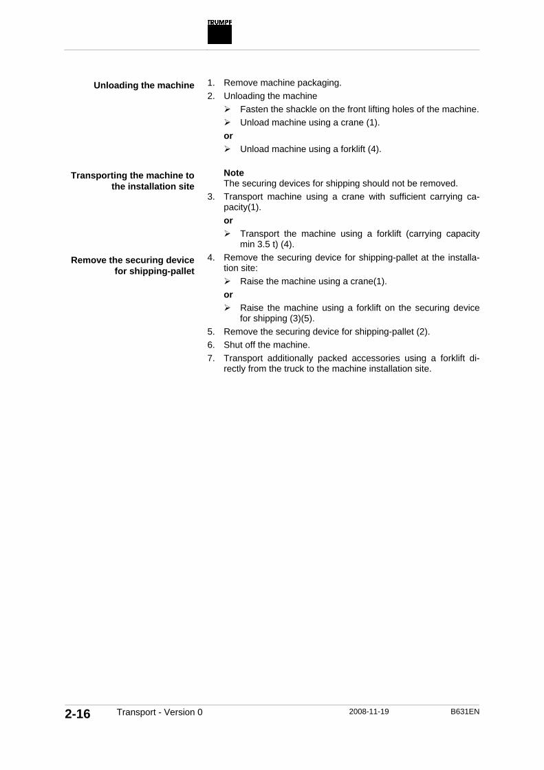
1. Remove machine packaging. 2. Unloading the machine
Fasten the shackle on the front lifting holes of the machine. Unload machine using a crane (1).
or Unload machine using a forklift (4).
Note The securing devices for shipping should not be removed.
3. Transport machine using a crane with sufficient carrying ca-pacity(1). or
Transport the machine using a forklift (carrying capacity min 3.5 t) (4).
4. Remove the securing device for shipping-pallet at the installa-tion site:
Raise the machine using a crane(1). or
Raise the machine using a forklift on the securing device for shipping (3)(5).
5. Remove the securing device for shipping-pallet (2). 6. Shut off the machine. 7. Transport additionally packed accessories using a forklift di-
rectly from the truck to the machine installation site.
Unloading the machine
Transporting the machine to the installation site
Remove the securing device for shipping-pallet

B631EN 2008-11-19 Description 3-1
Chapter 3
Description
1. Machine concept............................................................ 3-3
2. Technical data................................................................ 3-5
3. Machine axes ................................................................. 3-6
4. Modules of the machine................................................ 3-7 4.1 Nameplate and CE marking............................................. 3-8 4.2 Machine frame ................................................................. 3-8 4.3 Press table....................................................................... 3-8 4.4 Beam................................................................................ 3-9 4.5 Electromechanical direct drive and safety brake............. 3-9 4.6 Tool clamp ..................................................................... 3-10
Manual tool clamping................................................ 3-10 Centrally mechanical tool clamping (optional).......... 3-11
4.7 Backgauge..................................................................... 3-11 3-axis backgauge...................................................... 3-12 6-axis backgauge (optional) ..................................... 3-13
4.8 Control system............................................................... 3-13 Graphical shopfloor programming (optional) ............ 3-13

3-2 Description 2008-11-19 B631EN
E-Shop...................................................................... 3-14 Help at the control system........................................ 3-14
4.9 Control panel ................................................................. 3-15 4.10 Foot switch..................................................................... 3-16 4.11 Safety device ................................................................. 3-17
Optoelectronic safety device: BendGuard with block laser................................................................. 3-17 Side safety doors...................................................... 3-18
4.12 Ergonomics.................................................................... 3-19 Comfort base plate (optional) ................................... 3-19 Standing and sitting aid (optional) ............................ 3-20 Comfort foot support (optional)................................. 3-20 Front iLED illumination (optional) ............................. 3-21 Rear iLED illumination (optional) .............................. 3-21
4.13 Line laser (optional). ...................................................... 3-22
5. Tools ............................................................................. 3-23 5.1 Tools from TRUMPF...................................................... 3-23

B631EN 2008-11-19 Machine concept 3-3
1. Machine concept
TruBend is a CNC-controlled press brake for bending of even me-tal sheets by forming.
The press brake is made up of the following components: • Machine frame. • Beam with tool holder for upper tools (punch). • Press table with tool holder for lower tools (die). • Beam drive. • Backgauge system for positioning of the workpiece.
In order to use a press brake for bending, a tool is required which is fastened on the beam or the press table. Typical tools used for this purpose are punches and dies. Punches are mostly fastened on the beam and dies on the press table.
Fig. 54413
How does a press brake function?

3-4 Machine concept 2008-11-19 B631EN
The tool to be used depends on bending method, raw material, material thickness and angle.
The workpiece is manually inserted into the machine. The work-piece is placed on the lower tool. It is pushed into the machine until it fits closely against the backgauge.
The stroke is triggered using the foot switch. The beam moves downwards. The punch presses the workpiece into the die of the lower tool. The workpiece is bent.
After the bending process, the beam moves upwards again. The workpiece can be removed and positioned for the next bending operation.

B631EN 2008-11-19 Technical data. 3-5
2. Technical data.
TruBend 7018 7036 Press force kN 180 360
Length of bend mm 510 1020
Installation height mm 300 300
Width between columns mm 422 932
Throat mm 150 150
Working height mm 1150 1150
Beam (Y axis) rapid traverse mm/s 220 220
Beam (Y axis) work cycle (depends on the die width, freely programmable) mm/s 0.1 - 25 0.1 - 25
Positioning accuracy of the beam (Y axis) mm ±0.001 ±0.001
Stroke of the beam (Y axis) mm 120 120
Length mm 1295 1805
Width mm 1320 1330
Height mm 2380 2380
Ground kg 1800 2600
Electrical connection kVA 5 6
Control system -
TASC 6000 Windows XPe Pentium M 1.1 GHz 15" touchscreen
Backgauge
Withdrawal speed mm/s 220 220
X axis speed mm/s 1000 1000
R axis speed mm/s 330 330
Z axis speed mm/s 1000 1000
Positioning accuracy of the X axis mm 0.04 0.04
Positioning accuracy of the R axis mm 0.06 0.06
Traverse path of the X axis mm 240 240
Maximum range before stop in the X direction mm 500 500
Traverse path of the R axis mm 80 80
Tab. 3-1

3-6 Machine axes 2008-11-19 B631EN
3. Machine axes
Machine axes
All axes are CNC-controlled and can be programmed through the control system.
Axis Description Y Upward and downward movement of the beam.
R1 and R2 Upward and downward movement of the back-gauge.
X1 and X2 Forward and backward movement of the gauge fingers.
Z1 and Z2 Movement of the backgauge towards the right and left.
Description of the axes
Fig. 54387
Tab. 3-2

B631EN 2008-11-19 Modules of the machine 3-7
4. Modules of the machine
1 Drive with safety brake 6 Base plate 10 Control panel 2 Line laser 7 Press table 11 Tool clamp 3 Front iLED illumination 8 Nameplate and CE marking 12 Backgauge 4 Side safety doors 9 Foot switch 13 Foot support 5 Beam
Fig. 54052
3-8 Modules of the machine 2008-11-19 B631EN
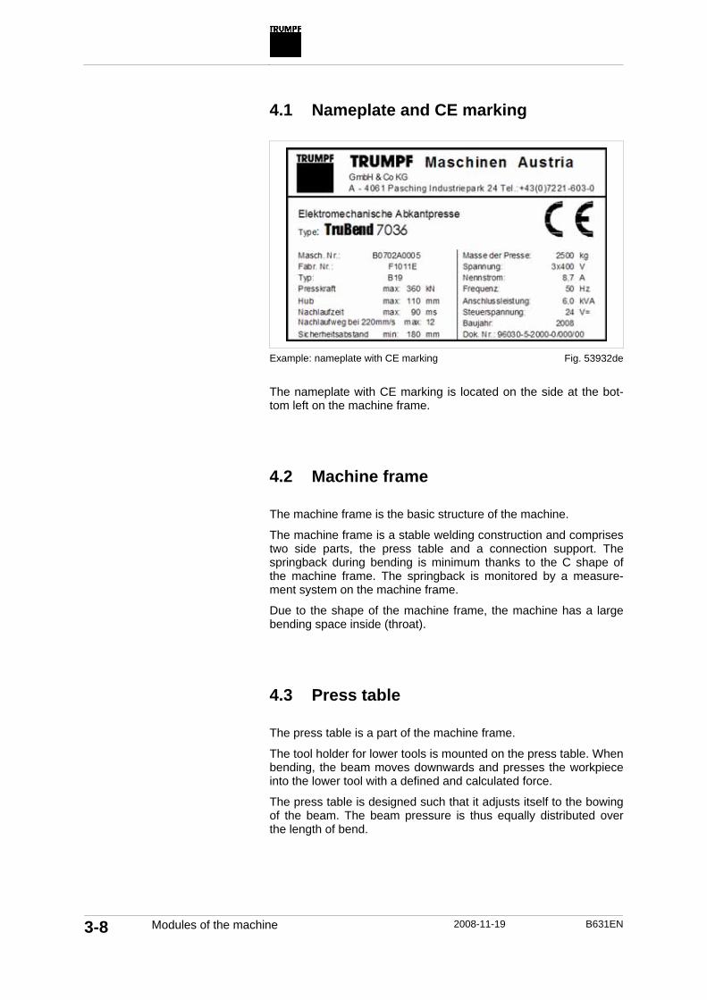
4.1 Nameplate and CE marking
Example: nameplate with CE marking
The nameplate with CE marking is located on the side at the bot-tom left on the machine frame. 4.2 Machine frame
The machine frame is the basic structure of the machine.
The machine frame is a stable welding construction and comprises two side parts, the press table and a connection support. The springback during bending is minimum thanks to the C shape of the machine frame. The springback is monitored by a measure-ment system on the machine frame.
Due to the shape of the machine frame, the machine has a large bending space inside (throat). 4.3 Press table
The press table is a part of the machine frame.
The tool holder for lower tools is mounted on the press table. When bending, the beam moves downwards and presses the workpiece into the lower tool with a defined and calculated force.
The press table is designed such that it adjusts itself to the bowing of the beam. The beam pressure is thus equally distributed over the length of bend.
Fig. 53932de

B631EN 2008-11-19 Modules of the machine 3-9
4.4 Beam
The beam is connected with the machine body through a guide and is moved using a drive. The drive is installed above the beam and moves it upwards and downwards.
The tool holder for upper tools is mounted on the beam. When bending, the beam moves downwards and presses the workpiece into the lower tool with a defined and calculated force. The position of the beam is controlled using the machine control system.
The beam has high bending rigidity. It is designed such that it does not bend at all or shows minimum bending in spite of the forces that act upon it during the bending process. The bending strength of the beam depends on the length of the bend of the machine and the position of the drives. 4.5 Electromechanical direct drive and
safety brake
The beam is driven with an electromechanical direct drive and is secured by a safety brake.
The electromechanical direct drive has one or two motors. The motor is connected directly to the beam and moves it upwards and downwards.
The downward movement of the beam must stop within a specific distance (springback) and a specific time (lag time). The spring-back and lag time values are specified on the nameplate.
If the beam does not stop within the springback and the lag time, the safety brake stops the machine drive. The beam movement stops.
Fig. 54383

3-10 Modules of the machine 2008-11-19 B631EN
The safety brake locks the drive at standstill and prevents the beam from falling.
The safety brake is installed above the motor. It consists of a brake disc and two brake callipers each. 4.6 Tool clamp
Tools are secured in a tool clamping. The tool clamping has one clamp for upper tools on the beam and one for lower tools on the press table.
The upper tool clamp is self-centering. This means that the tools are automatically aligned at the center above the press table dur-ing the clamping.
The lower tool clamp is installed on the press table. Manual tool clamping
The manual tool clamping is divided into individual segments. Every segment is opened and closed individually using adjusting screws on the front side.

B631EN 2008-11-19 Modules of the machine 3-11
Centrally mechanical tool clamping (optional)
The centrally mechanical tool clamping clamps the tool using the clamp piston.
The tool clamping is opened and closed by a detachable lever. The beam cannot be moved as long as the lever of the upper tool clamp is attached. 4.7 Backgauge
The backgauge has three axes: R, X and Z axis.
The backgauge is used to define the position of the workpiece.
The workpiece is manually inserted into the machine. The work-piece is placed on the lower tool. It is pushed into the machine until it fits closely against the gauge finger of the backgauge.
Every backgauge has a gauge finger on which the workpiece is butted.
The backgauge can, depending on the mode, move to the next programmed position at different times. The time of the movement is called step change.
Fig. 54050
3-12 Modules of the machine 2008-11-19 B631EN
Incremental switching
Setting at the control sys-tem Description
Manual (MSC)
Down button. Upper dead point, stop.
The backgauge moves to the next position when the BEAM DOWN foot switch is pres-sed.
Only for Tru-Bend series 5000: End de-compression.
The backgauge automatically moves to the next stop posi-tion at the end of the bending operation.
Only for Tru-Bend series 5000: Mute point.
The backgauge automatically moves to the next stop posi-tion when the beam has mo-ved upwards up to the mute point.
Automatic
Upper dead point.
The backgauge automatically moves to the next stop posi-tion when the beam has mo-ved upwards up to the upper dead point.
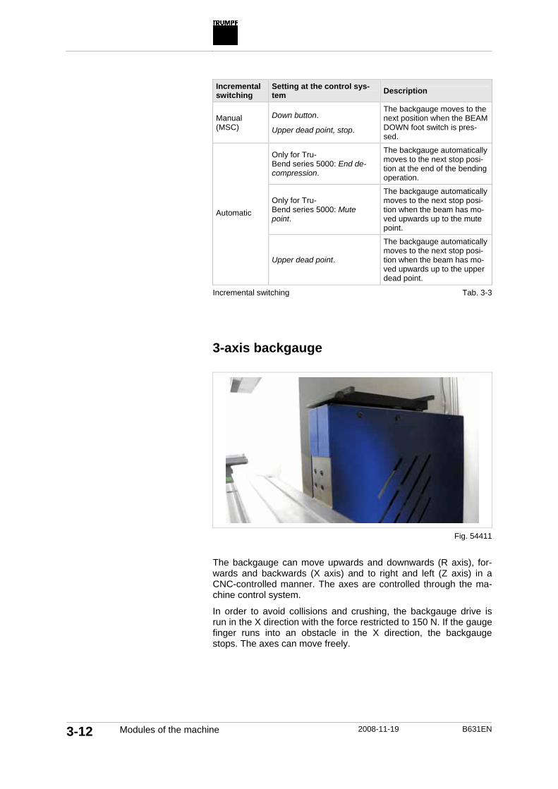
Incremental switching 3-axis backgauge
The backgauge can move upwards and downwards (R axis), for-wards and backwards (X axis) and to right and left (Z axis) in a CNC-controlled manner. The axes are controlled through the ma-chine control system.
In order to avoid collisions and crushing, the backgauge drive is run in the X direction with the force restricted to 150 N. If the gauge finger runs into an obstacle in the X direction, the backgauge stops. The axes can move freely.
Tab. 3-3
Fig. 54411

B631EN 2008-11-19 Modules of the machine 3-13
6-axis backgauge (optional)
The 6-axis backgauge comprises two 3-axis backgauges which move independently from each other. All 6 axes are controlled through the machine control system. 4.8 Control system
The machine is operated using the TASC 6000 control system with touchscreen. The control system is network-compatible.
The control system can be used for numerical or graphical (2D pro-files, optional) creation of programs. All CNC-controlled axes of the machine can be programmed using the control system.
Tools, materials and bend allowances are stored in the control system. Graphical shopfloor programming (optional)
Using the graphics shopfloor programming (BendGraph), simple profiles can be programmed graphically (2D) at the machine.
Functions of the graphical shopfloor programming: • Single bendings and round bendings can be programmed. • The 2D profile can be processed (e.g. mirrored) and modified. • The effective length of the bending part is displayed.
Fig. 54057

3-14 Modules of the machine 2008-11-19 B631EN
• The bending sequence is calculated automatically; it can how-ever be modified.
• Tools are automatically allocated to every bend. • A 3D simulation of the bending part, tools and gauge fingers is
displayed in the production. E-Shop
Tools can be ordered using the E-Shop on the control system if the control system has an Internet connection. The E-Shop on the control system contains all standard and special tools of the tool catalog.
Also in the E-Shop: the Information Service for Bending. The In-formation Service for Bending is a central platform with useful and interesting facts about the TruBend and bending tools. Help at the control system
The operator's manual is stored in the control system in the form of online help. The entire information about operation, maintenance, setting work etc. can be viewed using the online help.
Brief help texts for individual functions and input fields are dis-played in the F1 help. The F1 help can be opened and closed us-ing the <?> key.
Tools
Online help and F1 help

B631EN 2008-11-19 Modules of the machine 3-15
4.9 Control panel
1 Monitor with touchscreen 4 Changing to another window 7 EMERGENCY STOP impact
button 2 Number pad 5 Help key 8 START 3 Cursor keys 6 Tab key 9 STOP
The machine is operated using the touchscreen. All functions and input fields can be selected by pressing on the screen .
Numbers are entered using the number pad. For entering letters, a keyboard is displayed on the control system.
Programs, tools, archive and data can be loaded and imported into the control system via the USB connection. The USB connection for the control system is located outside on the right near the con-trol panel.
Fig. 53202

3-16 Modules of the machine 2008-11-19 B631EN
The slewable control panel can be bent towards the front. The an-gle of inclination can be set using the control system. 4.10 Foot switch
There are two foot switches: Beam down and Emergency-up.
1 Emergency-up foot switch 2 Beam down foot switch with stop
function
The BEAM DOWN foot switch has three positions:
Position Description 0 Not pressed The beam stands still or stops.
Slewable control panel (op-tional)
Fig. 54377
Fig. 54382
Beam down foot switch with stop function

B631EN 2008-11-19 Modules of the machine 3-17
Position Description 1 Pressed The beam moves downwards.
2 Pushed through The axes motion stops. The safety brake is activated.
The EMERGENCY-UP foot switch can be used to move the beam upwards. The EMERGENCY-UP foot switch is not active if EMERGENCY STOP was triggered. The EMERGENCY-UP foot switch has two positions:
Position Description 0 Not pressed No effect on the beam.
1 Pressed The beam moves upwards. The control system remains set to START.
4.11 Safety device
Optoelectronic safety device: BendGuard with block laser
The optoelectronic safety device monitors the area below the up-per tool during a light field operation.
The beam moves at the maximum speed (up to 220 mm/s) be-tween the upper dead point and the mute point The optoelectronic safety device monitors the area in front of and below the upper tool. If the light field is interrupted during operation, the beam stops moving.
The beam moves at a reduced speed between the mute point and the lower dead point. The optoelectronic safety device monitors the area below the tool tip of the upper tool. If the light field is inter-rupted during operation, the beam stops moving.
Tab. 3-4
Emergency-up foot switch
Tab. 3-5

3-18 Modules of the machine 2008-11-19 B631EN
A Viewing direction from the front
Light field of the BendGuard with block laser
The transmitter of the block laser projects a light field on the re-ceiver. The light field consists of individual laser beams. The trans-mitter is installed to the left and the receiver to the right on the machine.
The light field covers the lower part of the upper tool. The area around the tool tip is monitored. The beam will stop if the light field is interrupted in this area. Side safety doors
The side safety doors secure the area to the side of the beam and the press table. When the safety doors are closed, the danger zo-ne cannot be accessed from the side.
If both the side safety doors are opened during operation: • The axes motion stops. • The safety brake is activated.
If one of the side safety doors is opened during operation: • The axes motion stops. • The opening can be confirmed with the Beam down foot
switch. All axes can again be moved. The beam moves only at a reduced speed.
How does the BendGuard with block laser function?
Fig. 54381

B631EN 2008-11-19 Modules of the machine 3-19
4.12 Ergonomics
Comfort base plate (optional)
The comfort base plate is installed in the front on the press table and supports the lower arms during sedentary operation. Its height can be adjusted (eight different positions) and it can be folded.
Fig. 54384
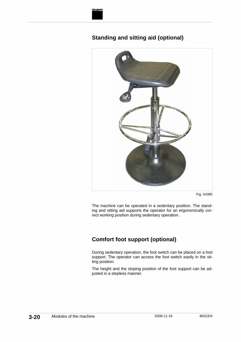
3-20 Modules of the machine 2008-11-19 B631EN
Standing and sitting aid (optional)
The machine can be operated in a sedentary position. The stand-ing and sitting aid supports the operator for an ergonomically cor-rect working position during sedentary operation. Comfort foot support (optional)
During sedentary operation, the foot switch can be placed on a foot support. The operator can access the foot switch easily in the sit-ting position.
The height and the sloping position of the foot support can be ad-justed in a stepless manner.
Fig. 54385
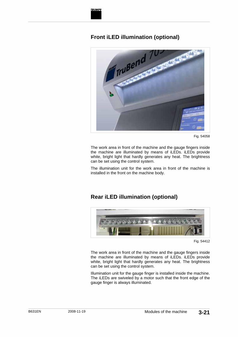
B631EN 2008-11-19 Modules of the machine 3-21
Front iLED illumination (optional)
The work area in front of the machine and the gauge fingers inside the machine are illuminated by means of iLEDs. iLEDs provide white, bright light that hardly generates any heat. The brightness can be set using the control system.
The illumination unit for the work area in front of the machine is installed in the front on the machine body. Rear iLED illumination (optional)
The work area in front of the machine and the gauge fingers inside the machine are illuminated by means of iLEDs. iLEDs provide white, bright light that hardly generates any heat. The brightness can be set using the control system.
Illumination unit for the gauge finger is installed inside the machine. The iLEDs are swiveled by a motor such that the front edge of the gauge finger is always illuminated.
Fig. 54058
Fig. 54412

3-22 Modules of the machine 2008-11-19 B631EN
4.13 Line laser (optional).
The line laser projects a line on the sheet in order to indicate the bending line.
During the bending process, the line laser is automatically switched off when the beam moves down from the clamping point. This pre-vents laser reflections during the bending process.
If the beam is at the upper dead point for longer than five minutes, the line laser is automatically switched off.
Fig. 54378

B631EN 2008-11-19 Tools 3-23
5. Tools
5.1 Tools from TRUMPF
In order to use a press brake for bending, a tool is required which is fastened on the beam or the press table. Typical tools used for this purpose are punches and dies. Punches are mostly fastened on the beam and dies on the press table.
The tool to be used depends on bending method, raw material, material thickness and angle.
All tools from TRUMPF that can be used for the TruBend have al-ready been stored in the control system. Data for special tools is delivered along with the special tools and must be imported.
Tools can be ordered using the E-Shop or the tool catalog.

3-24 Tools 2008-11-19 B631EN
1 Upper tool 5 Die width 2 Workpiece 6 Lower tool radius 3 Internal workpiece radius 7 Upper tool radius 4 External workpiece radius 8 Lower tool
Tool and workpiece
Head-bearing and shoulder-bearing tools are available. Shoul-der-bearing tools transfer the press force evenly onto the work-piece, even with large tool effective depths or lateral forces (e.g. with seams) that may appear.
Head-bearing upper tools up to 100 mm in length are equipped with Safety Click. This safety device prevents the tools from falling out of the tool clamping. The lock can be released by pushing a button: • The upper tools can be changed quickly and safely in vertical
position. • Short tool set-up times, because there is no need of sliding out
laterally from the upper tool clamp.
Fig. 12763
Head-bearing and shoul-der-bearing tools
Safety-Click safety element

B631EN 2008-11-19 Tools 3-25
The work surfaces and radii of all tools and the support areas of the lower tool clamp are hardened. This has the following advan-tages: • Long service life of the tools. • High levels of machine accuracy maintained over a long time.
All tools exist in various divisions and lengths that can be com-bined with one another: • Several tool stations can be used. • Reduced tool costs. • Time-efficient operation.
TRUMPF upper tools can be inserted on both sides.
The upper tool clamp for TRUMPF tools is self-centering. The up-per tools need not be aligned.
TRUMPF LASERdur bending tools
Tools of varying lengths
Can be used for folding over
Self-centering

3-26 Tools 2008-11-19 B631EN

B631EN 2008-11-19 Operation 4-1
Chapter 4
Operation
1. Description of the operating elements ........................ 4-5 1.1 Foot switch....................................................................... 4-5 1.2 Control panel ................................................................... 4-6 1.3 User interface .................................................................. 4-7
User interface layout................................................... 4-7 1.4 Operating elements at the switch cabinet...................... 4-10
2. Operating modes ......................................................... 4-11
3. Switching on the machine .......................................... 4-12 3.1 Releasing emergency stop/Emergency shutdown ........ 4-12 3.2 Switching on the machine.............................................. 4-12
4. Switching off the machine .......................................... 4-14 4.1 Switching off the machine in the case of
malfunctions................................................................... 4-14 4.2 Switching off the machine.............................................. 4-14
5. Behavior in case of emergency and malfunctions ................................................................ 4-15

4-2 Operation 2008-11-19 B631EN
5.1 Rescuing trapped persons............................................. 4-15
6. Optoelectronic safety devices (optional) .................. 4-16 6.1 Activating the optoelectronic safety device.................... 4-16 6.2 Avoiding dirt ................................................................... 4-16 6.3 Checking the function of the BendGuard....................... 4-16 6.4 Check the light field of the BendGuard using block
laser ............................................................................... 4-17 6.5 Operating the machine without optoelectronic
safety devices ................................................................ 4-18
7. Manual operation ......................................................... 4-19 7.1 Defining the basic parameters....................................... 4-19 7.2 Defining other parameters ............................................. 4-20 7.3 Programming an increased working speed ................... 4-20 7.4 Conducting collision check ............................................ 4-21 7.5 Producing individual bendings....................................... 4-22 7.6 Using user defined bending characteristics................... 4-22
8. Programming ............................................................... 4-23 8.1 Creating programs numerically...................................... 4-23
Creating a program................................................... 4-23 8.2 Creating programs graphically (optional)....................... 4-24
Creating a program................................................... 4-25 Creating profile ......................................................... 4-26 Deleting profile.......................................................... 4-28 Modifying profile........................................................ 4-28 Creating development. ............................................. 4-29
8.3 Defining tool stations ..................................................... 4-30 Programming tool stations........................................ 4-30
8.4 Displaying bending process (3D)................................... 4-32 Simulating bending process ..................................... 4-33 Adjusting the bending process ................................. 4-34
8.5 Defining bendings .......................................................... 4-35 Programming bendings ............................................ 4-35 Programming an increased working speed .............. 4-36
8.6 Using user defined bending characteristics................... 4-37 Using separate bending characteristics ................... 4-37
8.7 Check............................................................................. 4-38 Running program check ........................................... 4-38
8.8 Loading a program......................................................... 4-38 Loading a program ................................................... 4-38
8.9 Managing programs....................................................... 4-40 Importing/exporting program .................................... 4-41 Deleting a program ................................................... 4-42 Renaming a program................................................ 4-43

B631EN 2008-11-19 Operation 4-3
9. Production.................................................................... 4-44 9.1 Loading a program......................................................... 4-44 9.2 Creating a production plan............................................. 4-45 9.3 Displaying setup plan..................................................... 4-46 9.4 Defining corrections ....................................................... 4-46 9.5 Setting the safety mode ................................................. 4-47 9.6 Producing bending parts................................................ 4-48 9.7 Display production data ................................................. 4-48
10. Technology................................................................... 4-49 10.1 Managing tools .............................................................. 4-49
Creating a new tool................................................... 4-49 Editing a tool ............................................................. 4-52 Importing a tool ......................................................... 4-53 Exporting a tool......................................................... 4-54 Deleting a tool........................................................... 4-54 Managing tool groups ............................................... 4-55
10.2 Managing materials and raw materials.......................... 4-55 Creating raw materials.............................................. 4-56 Editing raw materials ................................................ 4-56 Deleting raw materials .............................................. 4-57 Creating material ...................................................... 4-57 Editing material ......................................................... 4-57 Deleting material....................................................... 4-58
10.3 Managing bend allowances ........................................... 4-58 Creating bend allowance .......................................... 4-58 Editing bend allowance............................................. 4-59 Deleting bend allowance .......................................... 4-59 Importing bend allowances....................................... 4-60 Exporting bend allowances....................................... 4-60
10.4 Creating user defined bending characteristic ................ 4-61 Creating a separate bending characteristic.............. 4-61
10.5 E-Shop........................................................................... 4-63 Procuring bending tools and spare parts online ....... 4-63
10.6 Program parameters...................................................... 4-63 Modifying default values ........................................... 4-63 Switching the functions on and off............................ 4-64 Switching off collision check ..................................... 4-64
10.7 PDF viewer .................................................................... 4-64 Displaying files using the PDF viewer ...................... 4-64
11. Maintenance & start-up ............................................... 4-66 11.1 Isolating options............................................................. 4-66 11.2 Activating options........................................................... 4-66 11.3 User management ......................................................... 4-67
Defining a user.......................................................... 4-67

4-4 Operation 2008-11-19 B631EN
11.4 Managing bending programs......................................... 4-68 Defining directories for bending programs ............... 4-68 Defining the criterion for the management of bending programs (classification)............................. 4-69
12. Diagnostics .................................................................. 4-70 12.1 Displaying current messages......................................... 4-70 12.2 Displaying all messages ................................................ 4-70
13. Help ............................................................................... 4-72

B631EN 2008-11-19 Description of the operating elements 4-5
1. Description of the operating elements
1.1 Foot switch
There are two foot switches: Beam down and Emergency-up.
1 Emergency-up foot switch 2 Beam down foot switch with stop
function
The BEAM DOWN foot switch has three positions:
Position Description 0 Not pressed The beam stands still or stops.
1 Pressed The beam moves downwards.
2 Pushed through The axes motion stops. The safety brake is activated.
The EMERGENCY-UP foot switch can be used to move the beam upwards. The EMERGENCY-UP foot switch is not active if EMERGENCY STOP was triggered. The EMERGENCY-UP foot switch has two positions:
Position Description 0 Not pressed No effect on the beam.
1 Pressed The beam moves upwards. The control system remains set to START.
Fig. 54382
Beam down foot switch with stop function
Tab. 4-1
Emergency-up foot switch
Tab. 4-2
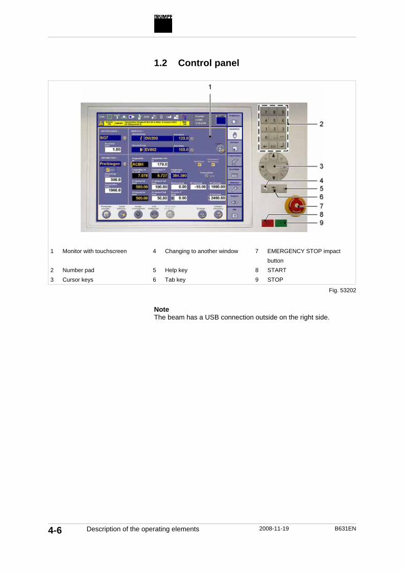
4-6 Description of the operating elements 2008-11-19 B631EN
1.2 Control panel
1 Monitor with touchscreen 4 Changing to another window 7 EMERGENCY STOP impact
button 2 Number pad 5 Help key 8 START 3 Cursor keys 6 Tab key 9 STOP
Note The beam has a USB connection outside on the right side.
Fig. 53202
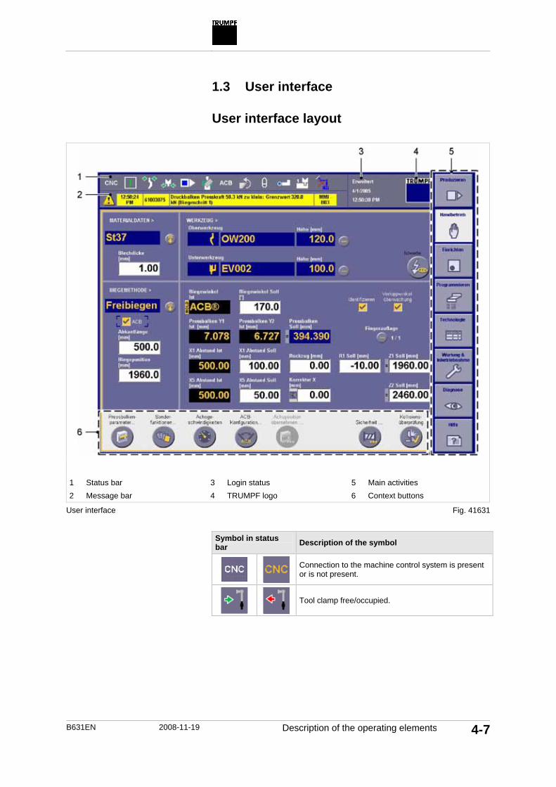
B631EN 2008-11-19 Description of the operating elements 4-7
1.3 User interface
User interface layout
1 Status bar 3 Login status 5 Main activities 2 Message bar 4 TRUMPF logo 6 Context buttons
User interface
Symbol in status bar Description of the symbol
Connection to the machine control system is present or is not present.
Tool clamp free/occupied.
Fig. 41631

4-8 Description of the operating elements 2008-11-19 B631EN
Symbol in status bar Description of the symbol
Program status: • A program is being read. • Program disabled. • Pause. • Execute a program. • Stop. • Program undefined.
Selected safety mode during the beam movement with block laser (four modes are possible).
Selected safety mode during the beam movement without optoelectronic protective device (two modes are possible).
Foot switch active or not active.
Possible stop positions: • Stopping front. • Placing and stopping second stage. • Placing and stopping third stage.
Remote diagnostics active.
The message bar is divided into 4 areas and is used to display in-formation (gray), warnings (yellow) and error messages (red): • The time at which the error occurred. • The corresponding error number. • A brief description of the error that occurred. • Source of the error: control system or machine element that
caused the error.
Note Details about information text, notes and error messages are listed under Diagnostics.
Three informative fields are displayed to the right, next to the sta-tus bar and the message line: • Logged-on user. • Current date. • Current time.
Tab. 4-3
Message line
Login status

B631EN 2008-11-19 Description of the operating elements 4-9
Note Language, unit of measure, and (your own) password can be changed by clicking on the information displayed in the log-on sta-tus.
The following functions can be initiated by clicking the TRUMPF logo: • Switch off machine. • Change user.
Main activity Function in the main activity
• Loading programs. • Displaying setup plan. • Producing programs. • Initiating program/global corrections.
• Programming and producing a single bend.
• Creating programs. • Modifying existing programs. • Selecting tools. • Making interventions in the processing se-
quence.
• Managing tools, materials and bend allow-ances.
• Configuring ACB data. • E-Shop (ordering spare parts and tools). • Adjusting program parameters. • Adjusting the illumination on the machine.
• Maintenance overview. • Maintenance plan. • Machine configuration. • User management. • Screen functions. • Program backup.
• Viewing error messages. • Sorting error messages. • ACB status display. • Diagnostics tools.
Using Help (online operator's manual). Functions: • Search. • Index. • Bookmark.
TRUMPF logo
Main activities
Tab. 4-4

4-10 Description of the operating elements 2008-11-19 B631EN
A variety of input and position fields are available on the user in-terface that are marked in different colors in accordance with their functions: • White: direct input of numbers or letters is possible. • Black: actual values are displayed. No input possible. • Blue: calculated nominal values or parameters selected from
the lists or the tables are displayed. No direct input possible.
Clicking opens a list from which parameters such as bending method can be selected.
Clicking opens a dialog box from which, for instance, tools from a table can be selected. Filters can be set in the table in order to limit the selection.
The selection made in the dialog box can be saved with Apply or closed without saving with Cancel. 1.4 Operating elements at the switch
cabinet
1 SERVICE key switch (only in
USA and Canada) 3 CONTROL SYSTEM key switch
2 MAIN SWITCH with EMER-GENCY SHUTDOWNfunction
Operating elements on the rear side of the machine
Input and position fields
List selection
Dialog box
Fig. 53203

B631EN 2008-11-19 Operating modes 4-11
2. Operating modes
Operating mode
Description
Foot operati-on
• One operator. A foot switch is activated.
• Trigger the stroke with the BEAM DOWN foot switch.
Tab. 4-5

4-12 Switching on the machine 2008-11-19 B631EN
3. Switching on the machine
3.1 Releasing emergency stop/Emergency shutdown
The EMERGENCY STOP and EMERGENCY SHUTDOWN func-tions are located at the following points: • EMERGENCY STOP impact button on the control panel. • Main switch with EMERGENCY SHUTDOWN function.
Conditions • The side safety doors of the machine are closed. • The door of the switch cabinet is closed (USA and Canada).
To release the EMERGENCY STOP-impact button, rotate the impact button to the right and pull it out.
or To release EMERGENCY SHUTDOWN on the MAIN SWITCH,
turn the MAIN SWITCH to I. 3.2 Switching on the machine
Conditions • EMERGENCY STOP released. • The side safety doors of the machine are closed. • The door of the switch cabinet is closed. or • The CONTROL SYSTEM key switch is set to 1.
Caution
Backgauge fingers may collide with the loaded tools! The axis positions of the X and R axes currently programmed
in the manual mode must be suitable for the loaded tools, or Adjust the axis position of the X axis to >200 mm, or Remove the loaded tools.
1. Turn the MAIN SWITCH on the switch cabinet to I. The control system of the machine starts. This can take some time.
A loud noise can be heard.
The start page of the user interface appears.
Keyboard is displayed.

B631EN 2008-11-19 Switching on the machine 4-13
Note If the user does not log on within 20 s, the last logged-on user is automatically logged on (if no password has been stored).
2. To select "User": press and select user. or
Enter "User". 3. If required, enter "Password". 4. Close the displayed keyboard with <ESC>. 5. Press Log-on.
The user interface will open.
A loud noise can be heard.
Note The position of the BendGuard must match with the tool height programmed in the manual operation.
6. Check the defined position of the BendGuard. 7. Press START.
The beam moves upwards to the reference point.
The backgauges are referenced. They move at a reduced speed.
A loud noise can be heard. 8. Press the BEAM DOWN foot switch and keep it pressed.
The beam moves downwards. The structural brake test is conducted. A loud noise can be heard.
The machine is ready for operation.

4-14 Switching off the machine 2008-11-19 B631EN
4. Switching off the machine
4.1 Switching off the machine in the case of malfunctions
Press the EMERGENCY STOP impact button on the control panel.
4.2 Switching off the machine
1. Press the TRUMPF logo. The "Log off " screen appears.
2. Confirm with Yes. The start page of the user interface appears.
3. Select Switch off machine. The "Switch off machine" screen appears.
4. Confirm with Yes. The user interface is closed.
5. Wait until the message "It's now safe to turn off your computer" appears on the control panel.
6. Set the MAIN SWITCH to 0. The machine is switched off.

B631EN 2008-11-19 Behavior in case of emergency and malfunctions 4-15
5. Behavior in case of emergency and malfunctions
In case of emergencies and malfunctions that occur during the machine operation, the operator must distinguish between the fol-lowing on the basis of his professional experience: • EMERGENCY STOP: the beam stops. • EMERGENCY-UP: the beam moves upwards. • MAIN SWITCH: the machine is switched off.
• If a person's body part gets trapped in the machine. • When are body parts at the risk of getting trapped?.
• In all other situations.
• If the malfunction cannot be eliminated within a short time, e.g. in the case of maintenance work.
5.1 Rescuing trapped persons
Information plate on the machine
1. If emergency stop was triggered: release EMERGENCY STOP.
2. Press the EMERGENCY-UP foot switch. The beam moves upwards. The control system switches to STOP.
When should emergency-up be pressed?
When should emergency stop be pressed?
When should the main switch be set to 0?
Fig. 54408

4-16 Optoelectronic safety devices (optional) 2008-11-19 B631EN
6. Optoelectronic safety devices (optional)
Note The downward movement of the beam at a rapid speed >10 mm/s is only permitted when an optoelectronic safety device on the ma-chine is used. 6.1 Activating the optoelectronic safety
device
1. Maintenance & start-up, select"Machine configuration". 2. Under "MACHINE OPTIONS >", activate"Block laser". 6.2 Avoiding dirt
Transmitter and receiver of the block laser must be kept free of dirt.
1. Keep the transmitter and receiver windows free of dust, dirt, and oil.
2. Avoid scratches on the window in the beam area. 3. Clean the window only with a soft, slightly damp cotton cloth. 6.3 Checking the function of the
BendGuard
Before starting the work, it must be checked whether the Bend-Guard is working faultlessly. Do not trust the setting without first checking by yourself.
1. Interrupt the light field with an object during the closing move-ment at rapid speed. Downward movement of the beam stops.
2. Check the mute point.

B631EN 2008-11-19 Optoelectronic safety devices (optional) 4-17
6.4 Check the light field of the BendGuard using block laser
Correct alignment of the light field must be ensured after every tool change and at regular intervals.
Condition • The desired tool is loaded.
1 Display
1. Press Tool Align on the receiver The camera in the receiver is automatically aligned with the tool tip.
2. Checking the LED display on the receiver. The light field alignment is correct if the middle LED lights up.
The light field must be realigned if more or other LEDs light up.
Fig. 54610

4-18 Optoelectronic safety devices (optional) 2008-11-19 B631EN
6.5 Operating the machine without optoelectronic safety devices
The machine can be operated without an optoelectronic safety de-vice. In this mode, the beam moves at a safe speed of max 10 mm/s.
1. When the user interface is started up: acknowledge the mes-sage with the EMERGENCY-UP foot switch.
2. Either PressProduction >Safety. Press"BENDGUARD MODE >" 5 or 6. Apply
or PressManual operation >Safety. Press"BENDGUARD MODE >" 5 or 6. Apply
or Press Program, "Bendings", "Special functions". Press"BENDGUARD MODE >" 5 or 6.

B631EN 2008-11-19 Manual operation 4-19
7. Manual operation
A single bend is programmed in the Manual operation. This bend-ing operation can be processed immediately. 7.1 Defining the basic parameters
1. Press Manual operation. 2. To select the material: under "MATERIAL DATA >, press"
and select the desired material. 3. Enter "Sheet thickness". 4. To select the bending method: under "BENDING METHOD >,
press" and select the desired bending method. – Air bending. – Seaming. – Flattening. – Embossed bending. – Swivel bending (if swivel bending tools are stored in tool
management). – User (if user defined bending characteristics are stored).
5. Enter the "Length of bend". The bend position and the position of the gauge fingers (Z1 and Z2) are adjusted automatically.
6. Enter the "Bend position". 7. To select the upper or lower tools, use to open the tool
selection.
Note Only tools that have been created under Technology, "Tool Management" are displayed in the list. This also allows tool lists from TruTops Bend to be viewed. The selection of the list can be restricted using filters.
8. Select the desired tool from the list. The selected tool is displayed under "Preview>".
9. To select an adapter or a holder, use to select the desired tool. The selected adapter or holder is displayed under "Preview>".
The height of the selected adapter is displayed. 10. To install the tool or the adapter in the rotated position: activate
"Tool rotated" or "Adapter rotated". 11. Press Apply. 12. Enter geometry data for the bending. All the white fields can be
modified.
Selecting material data
Select bending method
Entering the length of bend and the bend position
Selecting tools
Entering bending data

4-20 Manual operation 2008-11-19 B631EN
7.2 Defining other parameters
Like a bending that has been created in Program(see "Opera-tion_Program_Create program numerically"), beam parameters, special functions and axis speeds can be modified or selected.
Note Only USA: Mute points 1 and 2 can be modified only by the "Customer administrator" user.
1. To modify beam parameters: press Beam parameters.... 2. Enter the beam parameters. 3. Press Apply. 4. To modify axis speeds: press Axis speeds. 5. Enter the axis speeds. 6. Press Apply. 7. To modify the BendGuard mode: press Safety....
Note "BendGuard Mode" is only displayed if the corresponding op-tion is activated under Maintenance & start-up, "Machine con-figuration".
8. Select "BendGuard mode". 9. For BendGuard modes 2 and 4: under "Nesting height", enter
the height of the lateral link plate. 10. Press Apply. 11. To switch off collision check of the backgauge: press Safety.... 12. Deactivate "Collision check". 13. Press Apply. 7.3 Programming an increased working
speed
Individual bends of a program can be programmed with an in-creased working speed (up to 25 mm/s).
The working speed of the beam is monitored and can be more than 10 mm/s only under the following prerequisites: • Tool with a permissible die width is selected (from die width 10
onwards). • The bending angle is 90°. • The correction of the Bending angle is smaller than or equal to
+10° (values between 0 and +10 are permissible). • BendGuard Mode 1, 2, 3 or 4 is selected.
Modifying beam parameters
Modifying axis speeds.
Modifying the safety mode
Switching off backgauge col-lision check

B631EN 2008-11-19 Manual operation 4-21
Note If a user-specific bending characteristic is used, an increased wor-king speed cannot be programmed.
1. PressProgram, "Bendings",>"Joint speed". or
PressManual operation, Joint speeds... .
Note The speed at which the beam moves downwards from the safe opening width (6 mm above the sheet) up to the clamping point.
2. Enter speed under "Y safe opening". – Possible values: 1 mm/s up to max 25 mm/s, depending on
the programmed die width.
Note Speed at which the beam moves downwards from the clamp-ing point up to the lower dead point.
3. Enter speed under "Y press". – Possible values: 1 mm/s up to max 25 mm/s, depending on
the programmed die width. The beam moves from the safe opening width to the upper dead point at an increased speed. 7.4 Conducting collision check
The graphics collision check is a structural test that is carried out at the clamping point and at the lower dead point.
1. Press Manual operation. 2. PressCollision check... .
The collision check is performed.
If the backgauge collision check is switched off under Safety..., then no collision check is carried out for the backgauge.
The detected collisions are displayed in the message line and can be viewed under Diagnostics, "Pending messages".
All existing collision messages are deleted on during a tool change.

4-22 Manual operation 2008-11-19 B631EN
7.5 Producing individual bendings
1. Press START. 2. Place the workpiece between the upper and the lower tool and
bring it against the backgauge. 3. To move the beam downwards: press the BEAM DOWN foot
switch. 7.6 Using user defined bending
characteristics
Bending characteristics (empirically determined) are stored in the control system for specific materials and tools. If a material or tool group is used for which no bending characteristics are stored, the lower dead point of the beam is calculated using a geometric formula.
If this yields excessive deviations in the nominal angle (so that corrections have to be entered), user-specific bending characteris-tics can be created.
Condition • A separate bending characteristic is created for the selected
combination of tools, raw material, sheet thickness and open-ing angle(see "Operation_Technology_Create bending char-acteristic").
Note The separate bending characteristic can be used only if a separate bending characteristic was stored for the combination of tools, raw material and sheet thickness. Under "Bending method", the User method is then shown.
1. Press Manual operation. 2. Select"Bending method" >User. The bending characteristic is used.

B631EN 2008-11-19 Programming 4-23
8. Programming
Programs can be programmed in the following ways: • Numerically (all bends programmed individually). • Graphically with graphics shopfloor programming (BendGraph,
2D profile drawing). • Only TruBend series 5000: Graphically in the profile editor in
TruTops Bend (optional). 8.1 Creating programs numerically
Creating a program
1. Press Programming, "Bending part". 2. Press New Program.
The "New bending part" screen appears. 3. Enter the data for the "DESIGNATION >":
– Enter"Description" (can be entered alphanumerically and is used for identifying the programs in the database).
– Enter "Drawing number". – Use to select classification name (classification name
can be entered manually or can be selected from the list. The program is saved in a subfolder of the same name in the selected storage unit) (see "Operation_Maintenance & start-up_Criterion for management").
4. Select "MATERIAL DATA >": – Use to select "Raw material". – Enter "Sheet thickness". – Enter "Quantity req.".
5. Deactivate "Create graphic 2D profile". or
If TruTops Bend is activated: select"Program type" >Nu-meric.
6. Press OK. A new program is created. The entries from steps 3 and 4 ap-pear on the user interface.
7. Fill in additional fields if desired.

4-24 Programming 2008-11-19 B631EN
8.2 Creating programs graphically (optional)
Using the graphics shopfloor programming (BendGraph), simple profiles can be programmed graphically (2D) at the machine.
Segments can be created in various ways:
Description
Creating segment: • Enter "Angle". • Enter "Side length".
Creating segment: • Enter "Angle" and "Dx". • or enter "Angle" and "Dy". • or enter "Dx" and "Dy".
Fig. 53199en
Creating segments in the BendGraph

B631EN 2008-11-19 Programming 4-25
Description
Creating segment with round bending: • Enter "Angle". • Enter "Side length". • Enter the "Radius" of the bend. • Enter "Number of segments". • The "Segment length" is calculated automatically.
Only TruBend series 5000: Creating segment with a seam: • Enter "Distance". • Enter "Seam length". • Select "Folding direction". • Enter "Number of segments". • The "Segment length" is calculated automatically.
Sketch mode: when this character appears in the drawing sheet, segments of the profile can be sketched directly in the drawing sheet. Sketching segment: • Tap on the drawing sheet. • Open "Details". • Make settings. • Press "Apply". • Enter values.
Creating a program
1. Press Programming, "Bending part". 2. Press New Program.
The "New bending part" screen appears. 3. Enter the data for the "DESIGNATION >":
– Enter"Description" (can be entered alphanumerically and is used for identifying the programs in the database).
– Enter "Drawing number". – Use to select classification name (classification name
can be entered manually or can be selected from the list. The program is saved in a subfolder of the same name in the selected storage unit) (see "Operation_Maintenance & start-up_Criterion for management").
4. Select "MATERIAL DATA >": – Use to select "Raw material". – Enter "Sheet thickness". – Enter "Quantity req.".
Tab. 4-6

4-26 Programming 2008-11-19 B631EN
5. Deactivate "Create graphic 2D profile". or
If TruTops Bend is activated: select"Program type" >Nu-meric.
6. Press OK. A new program is created. The entries from steps 3 and 4 ap-pear on the user interface.
7. Fill in additional fields if desired. Creating profile
Condition • Program (graphically, 2D) has already been created .
1. Press Programming, "BendGraph". 2. Press "Profile editor". 3. Use to open "Settings".
Note The settings are default settings. The selected values apply either to all segments or to all the following segments that are selected.
4. Defining Default settings. 5. Press Apply. 6. Either
Press . or
Press . or
To set the start point of the profile: tap on the drawing sheet.
To draw a segment: tap on the drawing sheet once again. 7. Enter values.
A preview of the segment is displayed. 8. Use to open "Details...". 9. Select Settings. 10. Press Apply. 11. Press "OK" ( ).
The segment is drawn. 12. To cancel the procedure: Press Cancel ( ).
The segment is not drawn.
Defining settings
Drawing the first segment

B631EN 2008-11-19 Programming 4-27
13. Either Press .
or Press .
or To draw a segment with round bending: press .
or Only TruBend series 5000: To draw a segment with a
seam: press . or
To draw a segment: tap on the drawing sheet. 14. Enter values.
A preview of the segment is displayed. 15. Open . 16. Select Settings. 17. Press Apply. 18. Press "OK" ( ).
The segment is drawn. 19. To cancel the procedure: Press "Cancel" ( ).
The segment is not drawn.
Note Segments can be modified directly in the profile editor or in the profile table.
20. Either Tap on the desired segment. Modify values. Press "OK" ( ).
or Press "Profile table". Select the desired segment. Modify values. Press "OK" ( ). To return to the profile editor: press "Profile editor".
Drawing further segments
Modifying segment

4-28 Programming 2008-11-19 B631EN
Note Segments can be deleted directly in the profile editor or in the profile table. Only the first or the last segment of the profile can be deleted.
21. Either Tap on the desired segment. Press "Delete..." ( ). Press Yes.
or Press "Profile table". Select the desired segment. Press "Delete..." ( ). Press Yes. To return to the profile editor: press "Profile editor".
22. To add the next segment to the other end of the profile: press Continue other side.
23. To flip, scale or rotate the entire profile: pressModify profile. 24. Make settings. 25. Press Apply.
The profile has been created. Deleting profile
Deleting the entire profile.
Condition • A profile is drawn.
1. Press Programming, "BendGraph". 2. Press "Profile table". 3. Press Delete profile. 4. Press Yes. Modifying profile
To modify a program at a later time, all modifications that affect the profile must be made directly in the profile.
Condition • A profile is drawn.
Deleting a segment
Continuing the profile draw-ing on the other side
Modifying profile

B631EN 2008-11-19 Programming 4-29
Note If the profile is subsequently modified, development, tool stations and bending data will be recalculated.
1. Press Programming, "BendGraph".
Note Segments can be modified directly in the profile editor or in the profile table.
2. Either Press "Profile editor". Mark the desired segment. Modify values. Press "OK" ( ).
or Press "Profile table". Select the desired segment. Modify values. Press "OK" ( ).
The profile has been modified. Creating development.
The drawn profile must be developed and the bending sequence must thereby be calculated. Tool stations and bendings are cre-ated and calculated automatically.
1. Press Programming, "BendGraph". 2. Press "Development".
The development is created.
Possible bending sequences are calculated.
The effective length of the profile is displayed.
Note All possible bending sequences are always calculated.
3. To display further calculated bending sequences: Press Other bending sequence.
4. To define the bending sequence: press Define bending se-quence....
5. Mark bendings according to the sequence. The bending sequence is defined.
6. To recalculate the bending sequence: press Calculate se-quence.
Creating development.
Using other calculated bend-ing sequences
Defining a bending sequence
Recalculating the bending sequence

4-30 Programming 2008-11-19 B631EN
7. To display the dimensioning of the development: press Show dimensions.
8. Press Process parameters. 9. Perform settings. 10. Press Apply. 8.3 Defining tool stations
Programming tool stations
The tool stations can be graphically programmed directly on the control system of the machine.
Note If the program was programmed with graphics shopfloor program-ming (BendGraph), the tool stations are created automatically.
1. Press Programming. 2. Press "Tools".
Tool station 1 is already preset by the control system. It can however be modified.
3. Enter the "Length" of the station. 4. If desired, enter the "Position" of the station. 5. To fix the position of the station: activate "Position fixed". 6. To position all tool stations centrally on the press table: press-
Centering set-up plan. 7. To define segmentation automatically: activate "Automatic
segmentation".
Note The segmentations of the tools that are actually present must have been stored in the tool database.
8. To take into account the number of tools actually available du-ring segmentation, activate "Consider tool storage position".
9. To create a new tool station: press New station... or
Press Copy station to copy a station. An additional tool station is displayed.
10. Enter the data of the copied or the new tool station. 11. Press Delete station to delete a station.
Displaying the dimensioning
Defining process data
Creating tool stations

B631EN 2008-11-19 Programming 4-31
12. To select the tool station to be processed, use to select the desired station. or
Click on the desired station. or
Use (Previous station) or (Next station) to select the desired station.
The selected station is marked in orange. 13. To select the upper or lower tools: use to open the tool
selection.
Note Only tools that have been created under Technology, "Tool management" are displayed in the list. This also allows tool lists from TruTops to be viewed. The selection of the list can be restricted using filters.
14. Select the desired tool from the list. The selected tool is displayed under "Preview>".
Note Only TruBend series 5000: Only seaming tools that have been created under Technology, "Tool management" are displayed in the list.
15. Only TruBend series 5000: To use a seam strip: select the de-sired seaming tool under "Lock seam type".
16. To select an adapter or a holder: use to select the desired tool. The selected adapter or holder is displayed under "Preview>".
The height of the selected adapter is displayed. 17. To install the tool or the adapter in the rotated position: activate
"Tool rotated" or "Adapter rotated". 18. Press Apply. 19. Press Edit segmentation.... 20. Either
Use to select the tool station under "Group". – Beam tool. – Table tool center. – Table lock seam front.
or Click on the desired tool station.
The selected tool station is marked in orange. 21. Select the desired tool under "TOOLS>".
22. Use in "SEGMENTATION >" to apply tool.
23. If necessary, use to remove the selected tool from the segmentation.
24. If necessary, use or to move the selected tool. 25. Press Apply.
Selecting tools
Editing segmentation
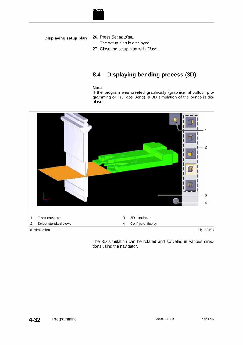
4-32 Programming 2008-11-19 B631EN
26. Press Set up plan.... The setup plan is displayed.
27. Close the setup plan with Close. 8.4 Displaying bending process (3D)
Note If the program was created graphically (graphical shopfloor pro-gramming or TruTops Bend), a 3D simulation of the bends is dis-played.
1 Open navigator 3 3D simulation 2 Select standard views 4 Configure display
3D simulation
The 3D simulation can be rotated and swiveled in various direc-tions using the navigator.
Displaying setup plan
Fig. 53197
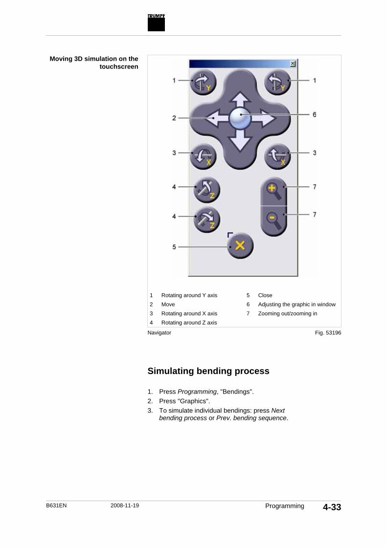
B631EN 2008-11-19 Programming 4-33
1 Rotating around Y axis 5 Close 2 Move 6 Adjusting the graphic in window 3 Rotating around X axis 7 Zooming out/zooming in 4 Rotating around Z axis
Navigator Simulating bending process
1. Press Programming, "Bendings". 2. Press "Graphics". 3. To simulate individual bendings: press Next
bending process or Prev. bending sequence.
Moving 3D simulation on the touchscreen
Fig. 53196

4-34 Programming 2008-11-19 B631EN
Adjusting the bending process
To optimize the bending process, the following settings can be made: • Rotate bending part. • Position gauge fingers. • Avoiding collisions through certain measures.
Note Rotate bending part and avoid collisions are possible only if the program was created with the graphical shopfloor programming (BendGraph) on the machine.
1. Press Programming, "Bendings". 2. Press "Graphics". 3. To rotate the bending part in the tool station: press Rotate
bending part. The bending part is rotated.
The position of the gauge fingers is adjusted automatically. 4. To change the position of the gauge fingers: press Adjust fin-
ger.... The Adjust finger menu is opened.
5. Make the desired settings. 6. To close the menu: press . 7. To avoid collisions: press Avoid collisions....
The collision avoidance wizard is opened. 8. Select the desired strategy for collision avoidance. 9. Press Next.
Note Modified settings are automatically saved.
10. Make settings.
Note The settings made previously are automatically saved.
11. To select a different/further strategy for collision avoidance: press Back.
Note If collisions occur because of the design of the bending parts, the only way to avoid these is by changing the design of the bending parts in "BendGraph" or in TruTops Bend.
12. Repeat steps 8 to 11 until no further collisions occur. 13. Press Finish.
The collisions are eliminated.
Rotate bending part.
Changing the position of the gauge fingers
Avoiding collisions

B631EN 2008-11-19 Programming 4-35
8.5 Defining bendings
Programming bendings
Note If the program was programmed with graphics shopfloor program-ming (BendGraph), the bendings are created automatically. Chan-ges in the bendings should then be made only in BendGraph. If bendings created in a graphically programmed program are mo-dified, these modifications are not applied to the profile. When the bendings are regenerated, these modifications are overwritten.
1. Press Programming. 2. Press "Bendings". 3. Press "Geometry".
The new bending part initially consists of only one single bend. The number of the bend is displayed on the left-hand side. The current bend is outlined in yellow.
4. Enter geometry data for bend 1.
Note Only USA: Mute points 1 and 2 can be modified only by the "Customer administrator" user.
5. Press"Beam parameters". 6. Enter beam parameters for bending 1.
Note "BendGuard Mode" is only displayed if the corresponding op-tion is activated under Maintenance & start-up, "Machine con-figuration". Only USA:"BendGuard mode" is set to mode 3 (with stop at the mute point).
7. If BendGuard is to be used for this bending operation: press"Special functions".
8. Select the desired special functions for bending 1. 9. For BendGuard modes 2 and 4: under "Nesting height", enter
the height of the lateral link plate. 10. If the axis speeds are to be modified: Press"Axis speeds". 11. Modifying axis speeds. 12. To create a new bend: PressNew bend....
or To copy a bend, pressCopy bending.
An additional bend is displayed on the left-hand side. The cur-rent bend is outlined in yellow.
13. Enter the data of the copied or the new bend as described in steps 2 to 8.
14. Press Delete bending. The current bend is deleted. The remaining bends are renum-bered.
Defining the data for the first bending operation
Defining additional bendings
Deleting bending

4-36 Programming 2008-11-19 B631EN
15. To move the sequence of the bendings, press Move bending operation... Move bends opens.
16. Select the bend which is to be moved. The selected bend is outlined in yellow.
17. Use or to move the bend up or down. 18. Press OK.
The bends are renumbered in accordance with the modified sequence.
Programming an increased working speed
Individual bends of a program can be programmed with an in-creased working speed (up to 25 mm/s).
The working speed of the beam is monitored and can be more than 10 mm/s only under the following prerequisites: • Tool with a permissible die width is selected (from die width 10
onwards). • The bending angle is 90°. • The correction of the Bending angle is smaller than or equal to
+10° (values between 0 and +10 are permissible). • BendGuard Mode 1, 2, 3 or 4 is selected.
Note If a user-specific bending characteristic is used, an increased wor-king speed cannot be programmed.
1. PressProgram, "Bendings",>"Joint speed". or
PressManual operation, Joint speeds... .
Note The speed at which the beam moves downwards from the safe opening width (6 mm above the sheet) up to the clamping point.
2. Enter speed under "Y safe opening". – Possible values: 1 mm/s up to max 25 mm/s, depending on
the programmed die width.
Note Speed at which the beam moves downwards from the clamp-ing point up to the lower dead point.
3. Enter speed under "Y press". – Possible values: 1 mm/s up to max 25 mm/s, depending on
the programmed die width.
Moving bendings

B631EN 2008-11-19 Programming 4-37
The beam moves from the safe opening width to the upper dead point at an increased speed. 8.6 Using user defined bending
characteristics
Bending characteristics (empirically determined) are stored in the control system for specific materials and tools. If a material or a tool group for which no bending characteristics are stored is used, the lower dead point of the beam is calculated using a geometric formula.
If this yields excessive deviations in the nominal angle (so that corrections have to be entered), user-specific bending characteris-tics can be created. Using separate bending characteristics
Condition • A separate bending characteristic is created for the selected
combination of tools, raw material, sheet thickness and open-ing angle (see "Operation_Prgramming_Separate bending characteristics").
Note The separate bending characteristic can be used only if a separate bending characteristic was stored for the combination of tools, raw material and sheet thickness. Under "Bending method", the method User is then shown.
1. Press Programming. 2. Press "Bendings". 3. Press "Geometry". 4. Select the desired bend. 5. Select the "Bending method"User.

4-38 Programming 2008-11-19 B631EN
8.7 Check
Running program check
The program check is a general test of the bending program. It is run automatically when the bending program is loaded in Produc-tion.
1. Press Programming. 2. Press Bending part.
Note Detected errors are displayed in "Program check xxx", and can be viewed under Diagnostics, "Pending messages " or "Mes-sage history".
3. Press Check.... The program check is carried out.
Only USA: If a bending operation was programmed with BendGuard mode without stopping at the mute point, a mes-sage is displayed.
Only USA: If manual incremental switching ("Down button") was programmed, a message is displayed.
All existing collision messages are deleted during a tool change. 8.8 Loading a program
Loading a program
Note Programs are always stored in subdirectories in the selected stor-age directory (depending on the classification, e.g. customer) (standard). The program storage unit can also be expanded in or-der to store programs in nested directories. All directories of the selected storage directory (e.g. C:\Programs) are displayed in the expanded program storage unit. More directories can be created. Example of standard directories: 'C:\Programs\Kunde\test.bnc' Example of nested directories: 'C:\Programs\Kunde\Jahr\Auftrags-Nr\test.bnc' To activate the expanded program storage unit, contact TRUMPF Customer Service Department.
1. PressProgramming, "Bending part". or
Press Production.

B631EN 2008-11-19 Programming 4-39
2. Press Load program.... The "Bending parts list" is opened.
3. Use to select "Storage unit". All programs that are saved in this folder are displayed in the list.
Note The list of programs can be restricted using filters or search functions.
4. To search for the designation, enter "Search string". All programs that contain the entered search string in the de-scription/file name, drawing number or in the comment are dis-played.
Note Only the classification names for which programs exist in the storage unit are offered in the selection list(see " Opera-tion_Maintenance & start-up_Criterion for management").
5. To search for programs of a special classification, use to select the classification name. All programs for the selected classification are displayed in the list.
6. To display additional search options, click the magnifying glass. "Description", "File name" and "Material" are displayed.
7. Use to select the "Material" to be searched for. All programs that use the selected material are displayed in the list.
8. To show descriptions or file names in the list, activate "De-scription" or "File name". Description or file name of the bending program are displayed in the list.
9. To sort the programs according to columns, click the column overview. – Description/File name. – Classification name. – Type. – Date.
10. To search for programs of a particular date, enter "Date from" and "to". All programs that were generated within the specified period are displayed in the list.
11. Select the program. The selected program is marked in yellow.
To the right, "Details>", "Preview>" (in the case of graphic pro-grams) and "Quantity>" of the selected program are displayed.

4-40 Programming 2008-11-19 B631EN
Note A program check is carried out automatically when a program is loaded. Detected errors are displayed in "Program check xxx", and can be viewed under Diagnostics, "Pending mes-sages " or "Message history".
12. Press Apply. The program check is carried out.
Only USA: If a bending operation was programmed with block laser mode without stopping at the mute point, a message is displayed.
Only USA: If manual incremental switching ("Down button") was programmed, a message is displayed.
The program is loaded. 8.9 Managing programs
The programs are created as per certain classifications, e.g. sorted by customer.
Note All programs that are stored in the selected directory are displayed in the bending parts list. Programs are always stored in subdirectories in the selected stor-age directory (depending on the classification, e.g. customer) (standard). The program storage unit can also be expanded in or-der to store programs in nested directories. In the expanded pro-gram storage unit, all directories of the selected storage directory (e.g. C:\Programs) are displayed. More directories can be created. Example of standard directories: 'C:\Programs\Kunde\test.bnc' Example of nested directories: 'C:\Programs\Kunde\Jahr\Auftrags-Nr\test.bnc' To activate the expanded program storage unit: contact TRUMPF Customer Service Department.
The following functions can be carried out in"Program manage-ment": • Importing/exporting programs. • Copying programs. • Creating a new version of a program. • Deleting a program. • Renaming a program. • Updating all programs of the selected storage unit.
Note Selecting programs(see "Operation_Programming_Load pro-gram").

B631EN 2008-11-19 Programming 4-41
Importing/exporting program
1. Press Programming. 2. Press "Bending part". 3. PressProgram management....
The "Bending parts list" is opened. 4. Use to select "Storage unit". 5. Press Import/Export...
"File transfer" is opened.
On the left, under "Directory", the path selected in step 4 is displayed along with all bending programs that are stored the-re.
6. To the right, under "Directory", select a directory to – Import programs (select the directory where the programs
that are to be imported are located). – Export programs (select the directory where programs are
to be exported into). 7. Either
Use to import all displayed programs from the external directory.
To import files created in TruTops, activate "Also copy TruTops files".
or Select file from the external directory. Use to import the selected program.
Note If a program is exported that is loaded in Programming, it is automatically saved before export.
8. Either Use to export all displayed programs from the internal
directory. To export files created in TruTops, activate "Also copy
TruTops files". or
Select file in the internal directory. Use to export the selected program.
9. Press Close. 10. Press Close.

4-42 Programming 2008-11-19 B631EN
Deleting a program
1. Press Programming. 2. Press "Bending part". 3. Press Program management....
The "Bending parts list" is opened. 4. Select the program.
The selected program is marked in yellow. 5. Press Delete....
The "Delete bending part " screen is opened.
Note If the bending program is deleted from the list, it is still stored in the storage unit, but is no longer displayed in the list. The pro-gram is displayed again the next time the storage unit is up-dated. If the bending program is deleted from the storage unit, it is deleted for good and cannot be recovered.
6. Either To delete the bending program from the list, press No.
or To delete the bending program for good (from the bending
part storage), press Yes.

B631EN 2008-11-19 Programming 4-43
Renaming a program
1. Press Programming. 2. Press "Bending part". 3. Press Program management....
The "Bending parts list" is opened. 4. Select the program.
The selected program is marked in yellow. 5. Press Rename ....
"Rename bending part " is opened.
Note The file name of the program does not change when the "De-scription" or Classification (e.g. "Customer") is modified.
6. Modify "Description", "Drawing number", or "Classification" 7. To modify the file name of the program or to move the program
(in the storage unit selected under "Classification"), activate "Change physical file name". The file name is changed according to the designation.
The (BNC) file is moved into a folder according to the entry under "Classification".
8. OK. The program is renamed and displayed in the list with the modified "Designation".

4-44 Production 2008-11-19 B631EN
9. Production
9.1 Loading a program
Note Programs are always stored in subdirectories in the selected stor-age directory (depending on the classification, e.g. customer) (standard). The program storage unit can also be expanded in or-der to store programs in nested directories. All directories of the selected storage directory (e.g. C:\Programs) are displayed in the expanded program storage unit. More directories can be created. Example of standard directories: 'C:\Programs\Kunde\test.bnc' Example of nested directories: 'C:\Programs\Kunde\Jahr\Auftrags-Nr\test.bnc' To activate the expanded program storage unit, contact TRUMPF Customer Service Department.
1. PressProgramming, "Bending part". or
Press Production. 2. Press Load program....
The "Bending parts list" is opened. 3. Use to select "Storage unit".
All programs that are saved in this folder are displayed in the list.
Note The list of programs can be restricted using filters or search functions.
4. To search for the designation, enter "Search string". All programs that contain the entered search string in the de-scription/file name, drawing number or in the comment are dis-played.
Note Only the classification names for which programs exist in the storage unit are offered in the selection list (see " Opera-tion_Maintenance & start-up_Criterion for management").
5. To search for programs of a special classification, use to select the classification name. All programs for the selected classification are displayed in the list.
6. To display additional search options, click the magnifying glass. "Description", "File name" and "Material" are displayed.
7. Use to select the "Material" to be searched for. All programs that use the selected material are displayed in the list.

B631EN 2008-11-19 Production 4-45
8. To show descriptions or file names in the list, activate "De-scription" or "File name". Description or file name of the bending program are displayed in the list.
9. To sort the programs according to columns, click the column overview. – Description/File name. – Classification name. – Type. – Date.
10. To search for programs of a particular date, enter "Date from" and "to". All programs that were generated within the specified period are displayed in the list.
11. Select the program. The selected program is marked in yellow.
To the right, "Details>", "Preview>" (in the case of graphic pro-grams) and "Quantity>" of the selected program are displayed.
Note A program check is carried out automatically when a program is loaded. Detected errors are displayed in "Program check xxx", and can be viewed under Diagnostics, "Pending mes-sages " or "Message history".
12. Press Apply. The program check is carried out.
Only USA: If a bending operation was programmed with block laser mode without stopping at the mute point, a message is displayed.
Only USA: If manual incremental switching ("Down button") was programmed, a message is displayed.
The program is loaded. 9.2 Creating a production plan
1. Press Production. 2. Press Production plan....
"Production plan" opens. 3. Press Add production plan....
A new production plan is added.
The production plan is marked in orange. 4. Enter "Name" and confirm with <ENTER>. 5. Enter "Piece" and confirm with <ENTER>.
Creating a new production plan

4-46 Production 2008-11-19 B631EN
The quantity can be entered to define how often the production plan should be executed.
6. If the production plan has already been executed, then enter the actual quantity "Act. pcs" and confirm with <ENTER>.
7. Press Add bending part.... The "Bending parts list" is opened.
Note The list of programs can be limited using a search string or one of the filters. The list of the programs can be sorted by table headings.
8. Select the desired program. The program is selected in orange.
9. Press Apply. The program is added to the production plan.
10. To add more programs, repeat steps 7 to 9 as many times as necessary until all desired programs have been added.
11. To delete programs, select the program and press Remove bending part.
12. Select the desired production plan. 13. Press Update.
The programs of the production plan are updated. 14. Select the desired production plan. 15. Press Delete production plan.
The production plan is deleted. 16. Select the desired production plan. 17. Press Load production plan. 18. Press Close.
The production plan is loaded and can be processed. 9.3 Displaying setup plan
1. Press Production. 2. Press Set up plan....
The setup plan is displayed. 9.4 Defining corrections
1. Press Production. 2. Press Corrections...
Adding program
Removing program
Updating Production plan
Deleting production plans
Loading production plan
Enter local corrections

B631EN 2008-11-19 Production 4-47
Note All the white fields can be modified.
3. Enter corrections. – Angle correction. – X correction. – LDP correction. – Parallelism – Only TruBend series 5000: V crowning.
4. Press Global corrections.... "Global corrections..." opens.
Note All the required bending angles programmed in the active pro-gram are displayed.
5. Activate "Req. angle with". 6. Use to select "Req. angle with". 7. Enter "Correction". 8. Activate "Backgauge X".
Note All the backgauges positioned in the active program are dis-played.
9. Use to select "Backgauge X". 10. Enter "Correction". 11. Activate "Clamping point correction". 12. Use to select "Clamping point corr." 13. Enter "Correction". 14. To apply global corrections, even of already corrected values,
activate "Relative to previous adjustment values (Delta correc-tion)".
15. Press OK. The corrections are entered. 9.5 Setting the safety mode
1. Press Production. 2. Press Safety....
Note "BendGuard Mode" is only displayed if the corresponding op-tion is activated under Maintenance & start-up, "Machine con-figuration".
3. Select "BendGuard mode". 4. Under "Backgauge>", activate "Collision check off" 5. Press Close.
Entering global corrections
Setting the safety mode
Switching off the collision check between the back-
gauge and the die

4-48 Production 2008-11-19 B631EN
9.6 Producing bending parts
Condition • The desired program is loaded .
1. Press START. 2. Place workpiece between the upper and the lower tool and
bring it against the backgauge. 3. To move the beam downwards: press the BEAM DOWN foot
switch. 9.7 Display production data
The production data of all produced programs are summarized in an XML file, and can be displayed using the Internet browser.
Condition • Network connection of the machine.
Note The XML file for the production data can not be opened at the machine, but only at an external computer via a network connec-tion to the machine.
Open the 'Production.xml' file under '\\B050XAYYYY\Production' using the Internet browser.

B631EN 2008-11-19 Technology 4-49
10. Technology
Tab Description
"Tool manage-ment"
• Loading, creating, editing, copying and deleting tools. • Importing and exporting tools from a tool archive (e.g.
TruTops Bend).
"Tool groups" • Creating, editing and deleting tool groups. • Importing and exporting tool groups from a TruTops
Bend database.
"Material mana-gement"
• Creating, editing and deleting material. • Creating, editing and deleting raw material.
"Bend allowan-ces"
• Creating, editing and deleting bend allowances. • Importing and exporting bend allowances from a Tru-
Tops Bend database.
"E-Shop" Ordering tools online.
"Program para-meters." Making global settings.
Only Tru-Bend series 7000:"Illumination"
• Setting brightness of the illumination. • Modifying sloping position of the control panel. • Switching on the line laser to display the bending line.
"PDF viewer" Displaying PDF files.
"Bending curves" Creating user-specific bending characteristics.
10.1 Managing tools
The following tool types are managed separately: • "Upper tools." • "Lower tools." • "Radius inserts" (radius inserts for upper tools). • "Z bending tools". • Only TruBend series 5000:"Seaming tools". • "Holders" • "Adapters". • "Swivel bending tools" (Swivel bending tools). • "Swivel bending die" (WingBend tools). Creating a new tool
1. Press Technology. 2. Press "Tool management".
Tab. 4-7
Create tool

4-50 Technology 2008-11-19 B631EN
3. Either To create a new tool: press New.
or Select the desired tool. To copy an existing tool: press New from template.
"Tool data" is opened. 4. Press "Properties". 5. Press "Main properties". 6. Select or enter properties.
– DESCRIPTION > – GEOMETRY > – DEFINITION >
7. Press "Further properties". 8. Select or enter properties.
– GENERAL TOOL DATA> – SPECIFIC TOOL DATA >
9. Press "Segmentation". 10. To create a new tool width: press New.
– Select "Tool type". – Enter "Tool length". – Enter "Quantity" of tools.
11. To copy an existing tool width: press New from template. – Select "Tool type". – Enter "Tool length". – Enter "Quantity" of tools.
12. To delete a tool width: select the desired tool, press Delete tool type and confirm with OK.
Note To create window tools or gooseneck tools for instance, a front view of the tool must be inserted. Only in this way, the tool can be displayed in correct graphics and the collision check can be performed correctly. If two identical gooseneck tools (e.g. horn left, length 40 mm) are to be created, these must have minimal differences: Example: create a right hand gooseneck tool, length = 40 mm and another right hand gooseneck tool, length = 40.0001 mm.
Defining tool properties
Customizing segmentation
Inserting front view of the tool

B631EN 2008-11-19 Technology 4-51
13. Either Enter "File name of drawing".
or Use to select a drawing. Use to select the storage medium. Use or to select the path.
If the selected folder contains DXF or WZG files, then the-se are displayed on the right.
Use to skip to the next level up on the path. Use to select "File type".
If DXF files (*.dxf) are selected as the file type, then only DXF files are displayed in the list. If GEO files (*.wzg) are selected as the file type, then only WZG files are displayed in the list.
Select the desired file. Press Apply.
14. Select "Drawing". 15. Either
Enter "File name of drawing". or
Use to select a drawing. Use to select the storage medium. Use or to select the path.
If the selected folder contains DXF or WZG files, then the-se are displayed on the right.
Use to skip to the next level up on the path. Use to select "File type".
If DXF files (*.dxf) are selected as the file type, then only DXF files are displayed in the list. If GEO files (*.wzg) are selected as the file type, then only WZG files are displayed in the list.
Select the desired file. Press Apply.
or PressEdit in TruTops CAD. Draw or edit drawing with the tool wizard in TruTops CAD. Quit TruTops CAD.
16. Press OK. The tool is created.
Inserting a tool drawing

4-52 Technology 2008-11-19 B631EN
Editing a tool
1. Press Technology. 2. Press "Tool management". 3. Press Edit tool.
"Tool data" is opened. 4. Press "Properties". 5. Press "Main properties". 6. Select or modify properties.
– GEOMETRY > – DEFINITION >
7. Press "Further properties". 8. Select or modify properties.
– GENERAL TOOL DATA> – SPECIFIC TOOL DATA >
9. Press "Segmentation". 10. To create a new tool width: press New.
– Select "Tool type". – Enter "Tool length". – Enter "Quantity" of tools.
11. To copy an existing tool width: press New from template. – Select "Tool type". – Enter "Tool length". – Enter "Quantity" of tools.
12. To delete a tool width: select the desired tool, press Delete tool type and confirm with OK.
Note To create window tools or gooseneck tools, a front view of the tool must be inserted. Only in this way, the tool can be dis-played in correct graphics and the collision check can be per-formed correctly.
13. Either Enter "File name of drawing".
or Use to select a drawing. Use to select the storage medium. Use or to select the path.
If the selected folder contains DXF or WZG files, then the-se are displayed on the right.
Use to skip to the next level up on the path. Use to select "File type".
If DXF files (*.dxf) are selected as the file type, then only DXF files are displayed in the list. If GEO files (*.wzg) are selected as the file type, then only WZG files are displayed in the list.
Editing a tool
Modifying tool properties
Customizing segmentation
Inserting front view of the tool

B631EN 2008-11-19 Technology 4-53
Select the desired file. Press Apply.
or PressEdit in TruTops CAD. Draw or edit the drawing with the tool wizard in TruTops
CAD. Quit TruTops CAD.
14. Select "Drawing". 15. Either
Enter "File name of drawing". or
Use to select a drawing. Use to select the storage medium. Use or to select the path.
If the selected folder contains DXF or WZG files, then the-se are displayed on the right.
Use to skip to the next level up on the path. Use to select "File type".
If DXF files (*.dxf) are selected as the file type, then only DXF files are displayed in the list. If GEO files (*.wzg) are selected as the file type, then only WZG files are displayed in the list.
Select the desired file. Press Apply.
or PressEdit in TruTops CAD. Draw or edit the drawing with the tool wizard in TruTops
CAD. Quit TruTops CAD.
16. Press OK. The tool is modified. Importing a tool
Archive files (*.arv) of tools (e.g. from TruTops Bend) can be im-ported.
1. Press Technology. 2. Press "Tool management". 3. Press Import data record.
"Open file" is opened. 4. Use to select the storage medium. 5. Use or to select the path.
Inserting a tool drawing

4-54 Technology 2008-11-19 B631EN
If the selected folder contains ARV files, these will be displayed on the right.
6. Use to skip to the next level up on the path. 7. Select the desired file. 8. Press Apply. Exporting a tool
Tools can be exported as archive files (*.arv).
1. Press Technology. 2. Press "Tool management". 3. Select the desired tool. 4. Press Export data record.
"Save as" is opened. 5. Use to select the storage medium. 6. Use or to select the path.
If the selected folder contains ARV files, these will be displayed on the right.
7. Use to skip to the next level up on the path. 8. To create a new folder in the selected directory: press New
folder, enter the "Name of the new folder" and press OK. The new folder is created and can be selected.
9. Enter the "File name". 10. Press Apply. The tool drawing is saved as an ARV file and can be loaded in TruTops Bend when adding a tool. Deleting a tool
Deleted tools are deleted from the database.
1. Press Technology. 2. Press "Tool management". 3. Select the desired tool. 4. Press Delete tool.
"Delete tool" is opened. 5. Press OK. The tool is deleted from the database.

B631EN 2008-11-19 Technology 4-55
Managing tool groups
Tool groups are created so as to group together tools with similar properties (e.g. upper tools with the same tool radius). A reference tool is specified for every tool group.
Bend allowances, materials or bending characteristics are as-signed to tool groups. These are thus applicable for the tools of this tool group(see " Operation_Technology_Bend allowances")(see "Operation_Technology_Material and raw materials")(see " Opera-tion_Technology_Create bending characteristic").
The following tool groups are differentiated: • "Upper tool groups". • "Die groups" (lower tool groups).
1. Press Technology. 2. Press "Tool groups". 3. Press New group. 4. Select or enter values. 5. Press Apply.
The tool group is created. 6. Select the desired tool group. 7. Press Edit group. 8. Select or enter values. 9. Press Apply.
The tool group is edited. 10. Select the desired tool group. 11. Press Delete group. 12. Press OK.
The tool group is deleted. 10.2 Managing materials and raw materials
Materials and raw materials are differentiated: • Raw material: is defined in terms of properties such as tensile
strength, modulus of elasticity, specific weight etc. • Material: is a raw material in a specific form (e.g. sheet with a
specific sheet thickness).
Creating a tool group
Editing a tool group
Deleting a tool group

4-56 Technology 2008-11-19 B631EN
Creating raw materials
When a raw material is created, a relevant material (standard ma-terial) is automatically created. The material is created in the de-sired sheet thickness and with assignment to tool groups.
1. Press Technology. 2. Press "'Materials management". 3. Press "'Raw materials". 4. Press Create raw material.
"Raw material management" is opened. 5. Press "Raw material data".
Note The "Raw material name" can be freely assigned. The "DIN description" must be unique, and may be used only once, since it is used for internal calculations.
6. Select or enter values under "DESCRIPTION >" and "SPECI-FICATION>".
7. Press "Standard sheets". 8. For the desired sheet thickness in which a material of this raw
material is to be created, activate "Create". 9. For the desired sheet thickness in which a material of this raw
material is to be created, select "UT group" and "LT group". 10. Press OK.
The raw material is created.
The respective material in the desired sheet thicknesses is created with the desired tool groups.
Editing raw materials
Only the raw material properties can be modified.
1. Press Technology. 2. Press "'Materials management". 3. Press "'Raw materials". 4. Select the desired raw material. 5. Press Edit raw material.
"Raw material management" is opened. 6. Press "Raw material data". 7. Modify the values under "DESCRIPTION >" or "SPECIFICA-
TION>". 8. Press OK.
The raw material is modified.

B631EN 2008-11-19 Technology 4-57
Deleting raw materials
Raw material and the relevant material are deleted from the data-base if the raw material is deleted.
1. Press Technology. 2. Press "'Materials management". 3. Press "'Raw materials". 4. Select the desired raw material. 5. Press Delete raw material. 6. Press OK.
Raw material and material are deleted. Creating material
When a raw material is created, a relevant material (standard ma-terial) is automatically created. The material is created in the de-sired sheet thickness and with assignment to tool groups.
Further sheet thicknesses of the material can be created.
1. Press Technology. 2. Press "'Materials management". 3. Press "'Materials". 4. Use to select the desired raw material. 5. Press Create material.
"Materials management" is opened. 6. Enter "Sheet thickness". 7. Select the desired tool groups under "SPECIFIC MATERIAL
DATA >". 8. Press OK.
The material is created. Editing material
Materials are allocated to tool groups. This assignment can be mo-dified.
1. Press Technology. 2. Press "'Materials management". 3. Press "'Materials".

4-58 Technology 2008-11-19 B631EN
4. Use to select the desired raw material. 5. Select the desired material. 6. Press Edit material.
"Materials management" is opened. 7. Select the desired tool groups under "SPECIFIC MATERIAL
DATA >". 8. Press OK.
The tool group allocated to the material is modified. Deleting material
Individual materials (of a specific sheet thickness) can be deleted.
1. Press Technology. 2. Press "'Materials management". 3. Press "'Materials". 4. Use to select the desired raw material. 5. Select the desired material. 6. Press Delete material. 7. Press OK.
Material is deleted. 10.3 Managing bend allowances
Bend allowances depend on the following factors: • Raw material, material. • Sheet thickness. • Opening angle. • Bending method • Tool (tool group). Creating bend allowance
Bend allowances can be created for every material and every sheet thickness as per the opening angle and the bending method.
The bend allowance is calculated for all opening angles that lie between the opening angles already created for a material.

B631EN 2008-11-19 Technology 4-59
New bend allowances should be created if: • Bend allowances for special opening angles are required for an
existing material and sheet thickness. • New tool groups have been created. • The material has been created in a new sheet thickness. • New raw materials have been created.
1. Press Technology. 2. Press "Bend allowances". 3. Press Create factor. 4. Enter or select the values. 5. Press OK. The bend allowance is created. Editing bend allowance
1. Press Technology. 2. Press "Bend allowances". 3. Select the desired entry. 4. Press Edit factor. 5. Modify values. 6. Press OK. The bend allowance is modified. Deleting bend allowance
1. Press Technology. 2. Press "Bend allowances". 3. Select the desired entry. 4. Press Delete factor. 5. Press OK. The bend allowance is deleted.

4-60 Technology 2008-11-19 B631EN
Importing bend allowances
Archive files (*.arv) of bend allowances (e.g. from TruTops Bend) can be imported.
1. Press Technology. 2. Press "Bend allowances". 3. Press Import data record.
"Open file" is opened. 4. Use to select the storage medium. 5. Use or to select the path.
If the selected folder contains ARV files, these will be displayed on the right.
6. Use to skip to the next level up on the path. 7. Select the desired file. 8. Press Apply. Exporting bend allowances
Bend allowances can be exported as archive files (*.arv).
1. Press Technology. 2. Press "Bend allowances". 3. Select the desired entry. 4. Press Export data record.
"Save as" is opened. 5. Use to select the storage medium. 6. Use or to select the path. 7. Use to skip to the next level up on the path. 8. To create a new folder in the selected directory: press New
folder, enter the "Name of the new folder" and press OK. The new folder is created and can be selected.
9. Enter the "File name". 10. Press Apply. The tool drawing is saved as an ARV file and can be loaded in TruTops Bend when adding a tool.

B631EN 2008-11-19 Technology 4-61
10.4 Creating user defined bending characteristic
Bending characteristics (empirically determined) are stored in the control system for specific materials and tools. If a material or a tool group is used for which no bending characteristics are stored, the lower dead point of the beam is calculated using a geometric formula.
If this yields excessive deviations in the nominal angle (so that corrections have to be entered), user-specific bending characteris-tics can be created.
The bending characteristics depend on the: • Tool. • Raw material. • Sheet thickness. • Opening angle.
The separate bending characteristic can be used only if a separate bending characteristic was stored for the combination of tools, raw material and sheet thickness.
Under "Bending method", in the Manual operation(see "Op-erarion_Manual operation_Bending characteristic") and Program-ming(see "Operation_Programming_Separate bending characteris-tic")User can be selected. Creating a separate bending characteristic
Separate bending characteristics should be created if materials or tools are used for which no bending characteristics are stored in the database.
The separate bending characteristics should be created for a spe-cial angle range.
Example: A new material is used, with which mainly 90° bending are performed. In this case, three "Measuring points" should be defined for the bending characteristic: e.g. for 80, 90 and 100°. The values for all opening angles within this range will be calculated.
Condition • The desired tool is loaded.
Means, Tools, Materials • Sheet of the desired material and sheet thickness. • Desired tool. • Goniometer.
Using separate bending cha-racteristic

4-62 Technology 2008-11-19 B631EN
Note The tools must be loaded centrally in the machine.
1. Press Technology. 2. Use to display further file cards. 3. Press "Bending characteristic". 4. Use to select tools and press Apply.
Note Under "Raw material", the DIN description of the raw material is displayed and not the raw material name (see "Opera-tion_Technology_Create raw material").
5. Select or enter "MATERIAL DATA >". 6. Enter the "Bending angle, req.". 7. Press START on the control system.
Note The bend should be performed centrally on the machine.
8. Perform the bend. Enter the lower dead point of the beam (Y axis) under "Pene-tration depth".
9. Measuring the opening angle. 10. Enter the measured angle under "Actual angle". 11. Press Save.
The measuring point is entered. 12. Repeat steps 6 to 12 until all the desired measuring points ha-
ve been created. A bending characteristic will be created. The bending charac-teristic applies to the range between the measuring points with the smallest and the largest nominal angles.
13. Select the desired measuring point in the list. 14. Press Update measuring point.
The measuring point is outlined in orange. The values are en-tered under "MEASURING POINT >".
15. Repeat steps 6 to 11 . 16. Press Save.
The measuring point is overwritten. 17. Select the desired measuring point in the list. 18. Press Remove measuring point.
The measuring point is deleted. 19. Press Overview.
An overview of material and tool combinations for which at le-ast one measuring point has been created is displayed.
Creating measuring point
Creating further measuring points
Updating measuring points
Deleting measuring point
Displaying an overview of the measuring points
B631EN 2008-11-19 Technology 4-63
10.5 E-Shop
Procuring bending tools and spare parts online
Bending tools and spare parts can be ordered online directly from the control system via the E-Shop.
Condition • Internet connection (via modem, ISDN connection or network).
To make orders, the customer must be registered at TRUMPF.
1. Press "E-Shop". 2. Select the desired catalog and press Login.
Note Steps 3 to 5 are relevant only for the customers who are not yet registered.
3. Press Registration. The registration screen appears.
4. Enter the data. 5. Press Send.
After registering, TRUMPF assigns you a password. This al-lows only registered customers to access E-Shop, thus pro-tecting data.
6. Enter the user name and password. 7. Press Start.
Note The customer data must only be filled in once. It contains data such as contact person, delivery and invoicing address, etc.
8. Press Your data. 9. Enter the data. 10.6 Program parameters
Modifying default values
1. Press Technology. 2. Press "Program Parameters". 3. Modify the default values under "Press force". 4. To save the settings, select Save settings.
Starting E-Shop
First-time registration
Logging in to E-Shop
Creating customer data

4-64 Technology 2008-11-19 B631EN
Switching the functions on and off
1. Press Technology. 2. Press "Program Parameters". 3. To Switch on the functions, activate the box. 4. To Switch off the functions, deactivate the box. 5. To save the settings, select Save settings. Switching off collision check
1. Press Technology. 2. Press "Program Parameters". 3. To switch off the graphics collision check completely, deacti-
vate "Graphics collision check". 10.7 PDF viewer
PDF files can be displayed using the PDF viewer.
The PDF viewer enables the viewing of TruTops setup plans, tool setup plans etc. for instance Displaying files using the PDF viewer
Note The opened file is closed when the main activity is changed.
1. Press Technology, "PDF viewer". 2. Press Open file.
"Open file" is displayed. 3. Under "Storage medium selection", select the directory in
which the desired file is stored. 4. Under "Path", select the desired directory using + or -.
The files stored in the selected directory are displayed on the right in the list.
5. Select the desired file. The file is marked in orange.
6. Apply
Loading file

B631EN 2008-11-19 Technology 4-65
The selected file is opened. This can take some time depend-ing on the file size.
7. Use the following functions to view the file: – First page. – Page back. – Page forward. – Last page. – Adapt to window. – Page in window width. – Page in original size.
8. To load another file, press Open file. The already loaded file will be closed.
"Open file" is displayed. 9. Proceed as described in steps 1 to 6.
Viewing file
Loading another file
4-66 Maintenance & start-up 2008-11-19 B631EN
11. Maintenance & start-up
Tab Description "Maintenance overview" No function
"Machine confi-guration"
• Select the default language and unit of the user inter-face.
• Activating options (e.g. block laser).
"Machine opti-ons"
Isolating and activating options (e.g. ACB, bar code rea-der...).
"MMI configura-tion."
• Managing and selecting users and user groups. • Modifying user rights. • Defining storage location for bending programs. • Modifying the 3D simulation display.
"Screen" • Setting the screen brightness. • Modifying the touch-click behavior of the touchscreen.
11.1 Isolating options
1. Press Maintenance & start-up. 2. Press "Machine options". 3. Press Enter option code.... 4. Enter option code. 5. Press OK. The option is isolated. 11.2 Activating options
To operate different options of the machine, they must be con-nected to the machine and activated at the user interface.
1. Press Maintenance & start-up. 2. Press "Machine configuration". 3. Activate options. 4. To save the settings, press Save configuration and confirm
with OK.
Tab. 4-8

B631EN 2008-11-19 Maintenance & start-up 4-67
11.3 User management
Defining a user
Note If the user has logged on as Customer administrator (pass-word: trumpf), the rights of the user group can be extended as well as modified.
1. Press Maintenance & start-up. 2. Select "MMI configuration". Modify 3. Select "Group management". 4. Press New group.
A new group is created. 5. Enter "Group name" and confirm with <Enter>.
Note The newly created group can be based on all the groups cre-ated, including the group to which the active user is allocated. The rights of the selected basic group are adopted.
6. Use to select "Basic group". 7. Use to select the "Language"
applicable to this group. 8. Use to select the "Unit"
applicable to this group. 9. The number of allocated users is displayed under "Members". 10. Select "User management". 11. Press New user.
A new user is created. 12. Enter "User name" and confirm with <Enter>.
Note The user can only be allocated to the groups defined under "Group management".
13. Use to select the "User group" to which the user is to be allocated.
14. Use to select the "Language" applicable to this user. 15. Use to select the "Unit" applicable to this user. 16. Select the desired user.
Note Only the passwords of the subordinate users can be assigned or changed. Your own password cannot be changed at this point.
17. Press Change password. 18. Enter "New password". 19. Enter the password again under "Confirm password". 20. Press Apply.
The password is assigned or changed.
Creating a user group
Creating a user
Assigning/changing a pass-word

4-68 Maintenance & start-up 2008-11-19 B631EN
21. Select "User rights".
Note The groups created under "Group management" can be se-lected.
22. Use to select. 23. Select "Activity".
The selected activity is marked in orange.
Note Rights of the same or a lower level can only be assigned. The logged-on user cannot assign any rights that are superordinate to his/her own position. If the user has logged on as Customer administrator (pass-word: trumpf), the rights of the user group can be extended as well as modified.
24. Select "STATUS". – Normal. – Write-protected. – Blocked. – Invisible. The status is modified for the selected activity and for all lower level activities.
11.4 Managing bending programs
Defining directories for bending programs
1. Press Maintenance & start-up. 2. Select "MMI configuration". Modify 3. Select"Store program". Store 4. Use to "Select user".
The default directory and all further directories that have been added are displayed under "Directories for bending programs".
Note If "User-specific setting" is deactivated, the user-specific folder paths of the currently selected user are deleted. Therefore, first define the folder paths that apply to all users and then create the user-specific folder paths.
5. If the added directory should apply to all users, do not activate "User-specific setting". or
If the added directory should apply only to the selected user, activate "User-specific setting".
6. PressAdd directory....
Assigning rights
Adding a new directory

B631EN 2008-11-19 Maintenance & start-up 4-69
"Select folder" opens. 7. Use under "Storage medium selection" to select storage
medium. 8. To create a new folder, press New folder, enter the "Name of
the new folder" and confirm with OK. 9. Select the directory.
The selected directory is marked in orange. 10. Press Apply.
The new directory is displayed under "Directories for bending programs".
Note The default directory cannot be deleted.
11. Select the directory. The selected directory is marked in orange.
12. Press Remove. The directory is deleted.
Note The default directory cannot be deleted.
13. Deactivate "User-specific setting". All directories of the selected user created in addition to the default directory are deleted.
Defining the criterion for the management of bending programs (classification)
The classification defines the criteria for storing the bending pro-grams in the selected storage unit. If Customer is entered as clas-sification, a customer name can be entered when creating a new program. A subfolder is then created for the bending program in the storage unit that is named after the customer who was entered during programming. All bending programs, for which the same customer name was entered, are stored in this folder in the se-lected storage unit. The classification can be selected freely.
The definition of a classification establishes the desired order in the program storage unit.
1. Press Maintenance & start-up. 2. Select "MMI configuration". Modify 3. Select"Bending program folder". Modify 4. Enter the desired classification criterion under "Inscription for
classification". The classification is defined.
Deleting a directory
Deleting all directories
Defining a classification

4-70 Diagnostics 2008-11-19 B631EN
12. Diagnostics
Tab Description "Pending mes-sages" Displaying all current messages.
"Message histo-ry" Displaying all messages.
"CNC di-agnostics"
Starting the dynamic brake test and displaying the status of the CNC axes.
Only Tru-Bend series 5000:"ACB"
ACB diagnostics, ACB modules and ACB sensor values are displayed.
"Software versi-ons"
Information about the software version in use is dis-played.
"Remote di-agnostics" Switching remote diagnostics on and off
12.1 Displaying current messages
1. Press Diagnostics. 2. Press "Pending messages".
All current messages are displayed. Different types of mes-sages can be filtered out from these messages.
3. Press "Info", "Warning" or "Error". Only the message types with a check mark are displayed.
4. To display the details of a message: select the desired mes-sage and press Details. The "Message details" screen appears.
5. Press "Cause", "Effect", "Measure" or "Error location". 6. Press Close. 12.2 Displaying all messages
1. Press Diagnostics. 2. Press "Message history".
All messages are displayed. Messages can be filtered out from these messages according to the types of messages and the period of the message.
3. To filter out certain types of message types: press "Info", "Warning" or "Error". Only the message types with a check mark are displayed.
Tab. 4-9

B631EN 2008-11-19 Diagnostics 4-71
4. To filter messages by period: press and select the desired period.
5. To display the details of a message: select the desired mes-sage and press Details. The "Message details" screen appears.
6. Press "Cause", "Effect", "Measure" or "Error location". 7. Press Close.

4-72 Help 2008-11-19 B631EN
13. Help
Help contains the entire operator's manual.
You have the following options in Help: • Search. • Index. • Bookmark. • Start page. • Forward (displays the next page that has already been vie-
wed). • Back (displays the page last viewed).

B631EN 2008-11-19 Setting work 5-1
Chapter 5
Setting work
1. Tools ............................................................................... 5-2 1.1 Loading tools with manual tool clamping......................... 5-2 1.2 Loading tools with centrally mechanical tool
clamping........................................................................... 5-2
2. Mute point....................................................................... 5-4 2.1 Defining the mute point.................................................... 5-4
3. Optoelectronic safety device........................................ 5-5 3.1 BendGuard with block laser............................................. 5-5
Aligning the light field.................................................. 5-5

5-2 Tools 2008-11-19 B631EN
1. Tools
1.1 Loading tools with manual tool clamping
1. Open the beam with the EMERGENCY-UP foot switch until tools can be positioned comfortably.
2. If BendGuard is equipped with block laser: move the Bend-Guard backwards on the guide rail.
3. Loosen the hexagonal socket screws on the tool clamp. 4. Load the tool
Push the lower tool in from the side and position it. Push in the upper tool from the side without Safety-Click
and position it. or
Push the lower tool in from the side and position it. Insert the upper tool vertically with Safety-Click and posi-
tion it. 5. Tighten the hexagonal socket screws and fasten the tools in
place.
Note The upper tool clamp for TRUMPF tools is self-centering.
6. Upper tools that are not self-centering must be aligned by means of an idle stroke before the first bending.
1.2 Loading tools with centrally
mechanical tool clamping
1. Open the beam with the EMERGENCY-UP foot switch until tools can be positioned comfortably.
2. If BendGuard is equipped with block laser: move the Bend-Guard backwards on the guide rail.
3. Open the tool clamp with the lever. 4. Load the tool
Push the lower tool in from the side and position it. Push in the upper tool from the side without Safety-Click
and position it. or
Push the lower tool in from the side and position it. Insert the upper tool vertically with Safety-Click and posi-
tion it.

B631EN 2008-11-19 Tools 5-3
Note The beam cannot be moved as long as the lever is attached.
5. Close the tool clamp with the lever and pull the lever out.
Note The upper tool clamp for TRUMPF tools is self-centering.
6. Upper tools that are not self-centering must be aligned by means of an idle stroke before the first bending.

5-4 Mute point 2008-11-19 B631EN
2. Mute point
2.1 Defining the mute point
The mute point is defined automatically by the machine.
The mute point must be defined manually for the following mate-rial-tool combination: • Sheet thickness <1 mm. • Die width ≥40 mm.
1. Attach the magnetic plate to the side of the lower tool to cover the die width.
Note The magnetic plate can be moved upwards for the processing of corrugated sheets by the anticipated corrugation height. This prevents time-consuming stroke interruptions.
2. Slide the magnetic plate upwards by the amount of the sheet thickness.
3. Press the BEAM DOWN foot switch. The beam moves downwards.
The mute point is defined automatically: the indicator lamp on the BendGuard glows continuously underneath the mute point.
4. If the indicator lamp also flashes underneath the mute point: check the programmed sheet thicknesses and tools and define the mute point once again.

B631EN 2008-11-19 Optoelectronic safety device 5-5
3. Optoelectronic safety device
3.1 BendGuard with block laser
Aligning the light field
Means, Tools, Materials • Allen key SW 2 mm • Allen key SW 10 mm
1 Folding bar 3 Display 2 Screw
Note The receiver is fastened to the right on the beam.
1. Release the Velcro fastener of the folding bar (1) on the re-ceiver and push the folding bar upwards.
2. Loosen screws (2) and remove the cover.
Fig. 54608

5-6 Optoelectronic safety device 2008-11-19 B631EN
1 Nut 2 Lock nut
3. Slightly loosen the nuts (1) and lock nuts (2) on the Bend-
Guard.
Note The BendGuard may only be moved minimally.
4. Align the receiver until the middle LED lights up.
LED display Explanation
Move the receiver upwards until the middle LED lights up.
Move the receiver forwards until the middle LED lights up.
Move the receiver downwards until the middle LED lights up.
Move the receiver backwards until the middle LED lights up.
The receiver is outside the reception range. Move the receiver until the middle LED lights up.
The light field alignment is correct if the middle LED lights up.
The light field alignment is correct if the middle LED lights up. 5. Tighten the nuts and lock nuts on the BendGuard carefully. 6. Place the cover and tighten the screws. 7. Move the folding bar downwards and fasten it using Velcro
fastener.
Fig. 54609
Tab. 5-1

B631EN 2008-11-19 Maintenance 6-1
Chapter 6
Maintenance
1. General guidelines......................................................... 6-3
2. Maintenance Overview .................................................. 6-4
3. Lubrication ..................................................................... 6-5 3.1 Overview.......................................................................... 6-5 3.2 Maintenance Instructions................................................. 6-7
Backgauge.................................................................. 6-7 Y axis on the beam..................................................... 6-9 Beam drive................................................................ 6-10 Slewable control panel (optional) ............................. 6-12
4. Mechanical elements................................................... 6-13 4.1 Overview........................................................................ 6-13 4.2 Maintenance Instructions............................................... 6-14
Switch cabinet........................................................... 6-14 Illumination................................................................ 6-17 Optoelectronic safety device .................................... 6-18 Safety brake.............................................................. 6-19 Foot support.............................................................. 6-21

6-2 Maintenance 2008-11-19 B631EN
Tool clamp ................................................................ 6-22
5. Electrics........................................................................ 6-23 5.1 Overview........................................................................ 6-23 5.2 Maintenance Instructions............................................... 6-24
Safety doors.............................................................. 6-24 Energy supply chain on the backgauge ................... 6-24 BendGuard with block laser...................................... 6-26

B631EN 2008-11-19 General guidelines 6-3
1. General guidelines
Appropriate maintenance is a prerequisite for maintaining the qual-ity of the machine. It prevents operational malfunctions and their consequences.
Danger
Risk of fatal injury during maintenance work when the ma-chine is switched on!
If not explicitly stated otherwise: set the MAIN SWITCH to 0, lock the MAIN SWITCH, pull out the key.
Strictly observe the safety regulations.
• Clean the entire machine at regular intervals. • Brush off large particles of dirt or remove them using an indus-
trial vacuum cleaner.
Refer to the lubrication chart and maintenance instructions for the lubrication of the machine. The following points should also be ob-served: • Use only lint-free cleaning cloths and a thin-bodied spindle oil
("scavenge oil") to clean lubricating points. Do not use cleaning wool, kerosene or benzole.
• Do not mix synthetic lubricating oils with mineral oils or syn-thetic oils from other manufacturers, even if the synthetic oil in question has equivalent properties.
• Dispose of waste oil appropriately.
Notes on cleaning
Notes on lubrication

6-4 Maintenance Overview 2008-11-19 B631EN
2. Maintenance Overview
Inter-val/operating hours
Maintenance point Maintenance work Page
40 Switch cabinet Checking air conditioning unit for contamina-tion
6-14
40 Tool clamp Cleaning the tool clamp 6-22
500 Backgauge Lubricating the Z axis guide carriage 6-7
500 Backgauge Lubricating the racks (X and Z axis) 6-7
500 Y axis on the beam Lubricating the Y axis guide carriage 6-9
500 Beam drive Lubricate the beam drive 6-10
500 Slewable control panel (optional) Lubricating the spindle 6-12
500 Optoelectronic safety device Cleaning the guide for the BendGuard with block laser
6-18
500 Optoelectronic safety device Check the back stop for the BendGuard with block laser
6-19
500 Foot support Cleaning the guide 6-21
500 Safety doors Check the function of the safety switch on side safety doors
6-24
500 BendGuard with block laser Check proper functioning. 6-26
1000 Energy supply chain on the backgauge Check electrical supply lines 6-24
2000 Safety brake Conduct dynamic brake test 6-19
As needed Switch cabinet Cleaning the air conditioning unit 6-15
As needed Illumination Cleaning the lamp 6-17
As needed Optoelectronic safety device Cleaning the transmitter and receiver 6-19 For single shift operation the following relations hold: 40 operating hours weekly
500 operating hours every 3 months
1000 operating hours every 6 months
2000 operating hours annually

B631EN 2008-11-19 Lubrication 6-5
3. Lubrication
3.1 Overview
1 Spindle of slewable control panel 3 Rack for X and Z axis backgauge 5 Guide for Z axis backgauge 2 Guide carriage, Y axis 4 Beam drive
Lubrication chart
Fig. 54416

6-6 Lubrication 2008-11-19 B631EN
Symbol Explanation Symbol Explanation
Indication of lu-brication intervals in hours
Lubrication with a grease gun
Read the main-tenance instruc-tions
Lubricate with an oil can or spray can
Lubrication point Recommended lubricants Identification Visco-
sity
Spindle of slewable con-trol panel Rack for X and Z axis back-gauge
ARAL Degol BG 220 ARAL Deganit BG 221 BP Energol GR-XP 220 BP Maccurat 220 D CASTROL Alpha SP 220 CASTROL Magnaglide D220 ELF Reductelf SP 220 ELF Moglia 220 ESSO Spartan EP 220 ESSO Febis K 220 FUCHS Renolin CLP 220 FUCHS Renep 220 K MOBIL Mobilgear 630 MOBIL Vactra oil No. 4 SHELL Omala oil 220 SHELL Tonna oil 220
CG, CLP, CGLP
ISO VG 220
Guide carriage, Y axis Guide for Z axis backgauge
SHELL Alvania EP2 MOBIL Mobilux EP2 Klüber HEL 46-450
KP2K-20 NLGI 2
Beam drive Klüberplex BEM 41-132 KPHC2N-30L NLGI 2
Tab. 6-1
Tab. 6-2

B631EN 2008-11-19 Lubrication 6-7
3.2 Maintenance Instructions
Backgauge
(see "Overview", pg. 6-5) Maintenance intervall: 500 operating hours
Means, Tools, Materials • Phillips screwdriver.
1 Grease nipple
1. Switch off the machine properly, set the main switch to 0 and prevent the machine from being switched on again.
2. Loosen the screws on the rear protective cover slightly. 3. Pull the rear protective cover downwards and remove it. 4. Lubricate the guide carriage using a grease nipple. 5. Move the backgauge manually to left and right. 6. Repeat steps 4 and 5 three times. 7. Place the rear protective cover and screw it on. Maintenance intervall: 500 operating hours
Means, Tools, Materials • Phillips screwdriver. • Brush. • Kerosene.
100624: Lubricating the Z axis guide
carriage
Fig. 54388
100625: Lubricating the racks (X and
Z axis)

6-8 Lubrication 2008-11-19 B631EN
1 Rack
Rack, X axis
1 Rack
Rack, Z axis
1. Move the gauge finger completely to the front. 2. Switch off the machine properly, set the main switch to 0 and
prevent the machine from being switched on again. 3. Loosen the screws on the rear protective cover slightly. 4. Pull the rear protective cover downwards and remove it. 5. Clean contaminated racks and pinions with a brush and kero-
sene.
Fig. 54389
Fig. 54398

B631EN 2008-11-19 Lubrication 6-9
6. Apply rack grease on the racks and pinions on the X and Z axis using a brush.
7. Move the backgauge manually to left and right. 8. Move the gauge finger manually forwards and backwards. 9. Repeat steps 6, 7 and 8 three times. 10. Place the rear protective cover and screw it on. Y axis on the beam
(see "Overview", pg. 6-5) Maintenance intervall: 500 operating hours
Means, Tools, Materials • Phillips screwdriver.
1 Grease nipple
1. Switch off the machine properly, set the main switch to 0 and prevent the machine from being switched on again.
2. Loosen the screws on the rear protective cover slightly. 3. Pull the rear protective cover downwards and remove it. 4. Lubricate the guide carriage using a grease gun until the old
grease comes out on the guide rail. 5. Remove the old lubricant using a slightly oiled cloth. 6. Place the rear protective cover and screw it on. 7. Switch on the machine and move the beam upwards and
downwards. 8. Repeat all the steps twice.
100626: Lubricating the Y axis guide
carriage
Fig. 54392

6-10 Lubrication 2008-11-19 B631EN
Beam drive
(see "Overview", pg. 6-5) Maintenance intervall: 500 operating hours
Means, Tools, Materials • Phillips screwdriver. • Conductor.
1. Switch off the machine properly, set the main switch to 0 and prevent the machine from being switched on again.
2. Loosen the screws on the rear protective cover slightly. 3. Pull the rear protective cover downwards and remove it. 4. Loosen the screws on the upper protective cover.
Warning
Hot brakes and brake discs! Risk of burns.
Do not touch the brakes and brake discs. Wait until the brakes and brake discs cool down.
Warning
Mobile brake discs! Risk of injury
Never put your hands between the radii of the brake discs. Do not put your hands to the right or left of the machine fra-
me near the brake discs. 5. Remove the upper protective cover.
100643: Lubricate the beam drive

B631EN 2008-11-19 Lubrication 6-11
Note For TruBend 7036, lubricate both the drives.
1 Grease nipple
Beam drive from below 6. Lubricate the lower drive using a grease gun.
Note For TruBend 7036, lubricate both the drives.
1 Grease nipple
Beam drive from above 7. Lubricate the upper drive using a grease gun. 8. Place the upper protective cover and screw it on. 9. Place the rear protective cover and screw it on.
Fig. 54414
Fig. 54415

6-12 Lubrication 2008-11-19 B631EN
Slewable control panel (optional)
(see "Overview", pg. 6-5) Maintenance intervall: 500 operating hours
Means, Tools, Materials • Phillips screwdriver. • Brush. • Kerosene.
1 Spindle
1. Switch off the machine properly, set the main switch to 0 and prevent the machine from being switched on again.
2. Loosen the screws on the rear protective cover slightly. 3. Pull the rear protective cover downwards and remove it. 4. Clean contaminated spindle with a brush and kerosene. 5. Apply rack grease on the spindle using a brush. 6. Place the rear protective cover and screw it on.
100627: Lubricating the spindle
Fig. 54395
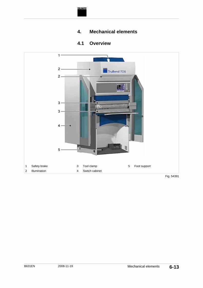
B631EN 2008-11-19 Mechanical elements 6-13
4. Mechanical elements
4.1 Overview
1 Safety brake 3 Tool clamp 5 Foot support 2 Illumination 4 Switch cabinet
Fig. 54391

6-14 Mechanical elements 2008-11-19 B631EN
4.2 Maintenance Instructions
Switch cabinet
(see "Overview", pg. 6-13) Maintenance intervall: 40 operating hours
Condition • The main switch on the switch cabinet is switched off and is
secured against being switched on again.
1 Fins 2 Covering 3 Fan wheels
Air conditioning unit
Note No filter mats should be used in the air conditioning units, be-cause these reduce the effectiveness of the air conditioning unit.
1. Pull off the covering. 2. Check fins and fan wheel for contamination. 3. Mount covering.
100007: Checking air conditioning
unit for contamination
Fig. 51914
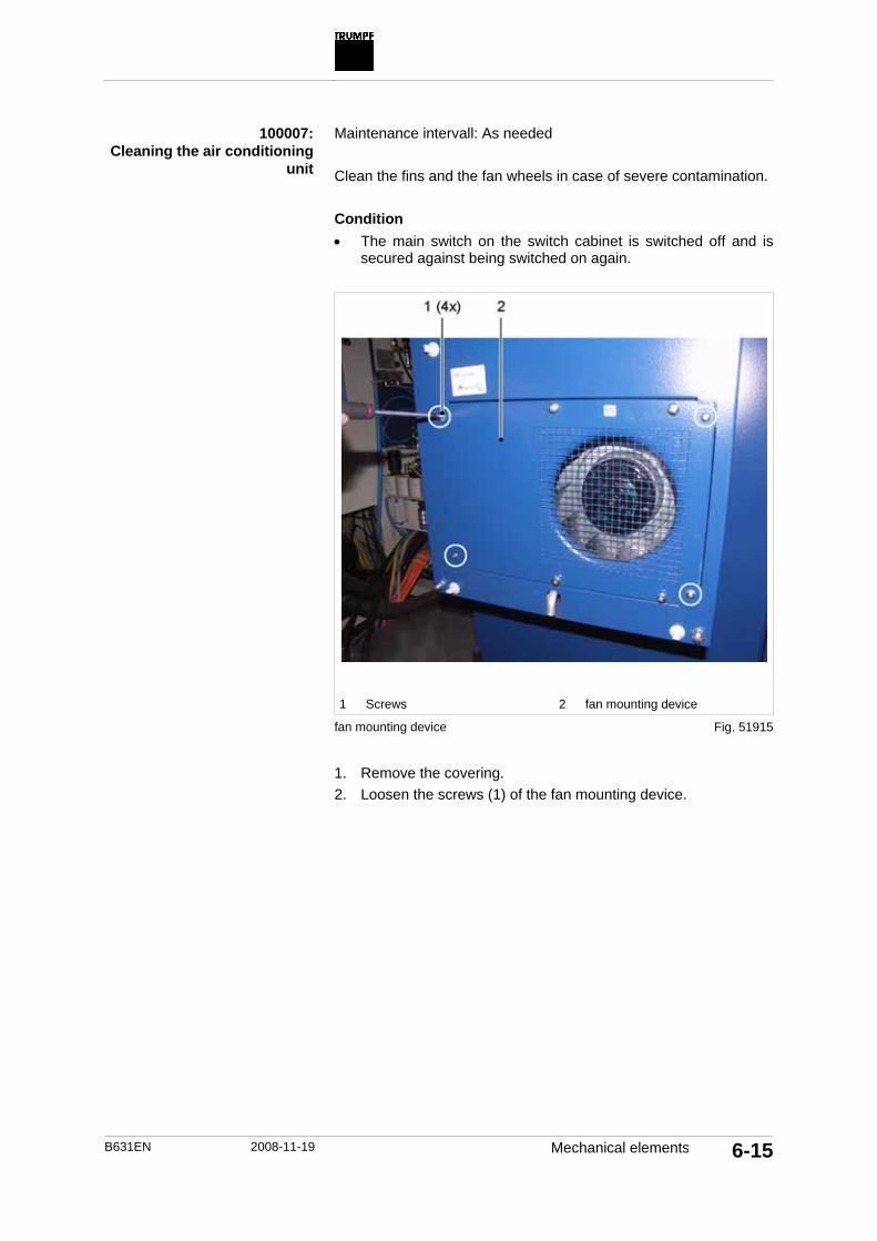
B631EN 2008-11-19 Mechanical elements 6-15
Maintenance intervall: As needed
Clean the fins and the fan wheels in case of severe contamination.
Condition • The main switch on the switch cabinet is switched off and is
secured against being switched on again.
1 Screws 2 fan mounting device
fan mounting device
1. Remove the covering. 2. Loosen the screws (1) of the fan mounting device.
100007: Cleaning the air conditioning
unit
Fig. 51915

6-16 Mechanical elements 2008-11-19 B631EN
1 Plug 2 Ground wire
Connection cable of the fan mounting device 3. Fold the fan mounting device (2) to the front. 4. Loosen the plug and the earth cable of the fan mounting de-
vice. The fan mounting device can now be removed completely.
Caution
Effect on the eyes and lungs due to whirling dust and dirt! Wear suitable protective gear when blowing the air condi-
tioning unit (safety glasses, dust protection glass).
5. Blow out the fan wheel with compressed air.
Fig. 51916

B631EN 2008-11-19 Mechanical elements 6-17
Carton in the opening of the fan mounting device 6. Insert a suitable carton into the opening of the fan mounting
device in order to protect the lower housing part for dirt. 7. Blow off fins from the front and from below through the opening
of the fan mounting device with compressed air. 8. Remove the box. 9. Plug in the fan mounting device again and mount the plug and
the earthing cable again. 10. Tighten the screws of the fan mounting device. 11. Insert the covering. Illumination
(see "Overview", pg. 6-13) Maintenance intervall: As needed
Means, Tools, Materials • Soft, clean cloth. • Window-cleaning agent.
Note Do not use any abrasive or aggressive agents for cleaning.
1. Switch off the machine properly, set the main switch to 0 and prevent the machine from being switched on again.
2. Clean the lamp with window-cleaning agent.
Fig. 51679
100631: Cleaning the lamp

6-18 Mechanical elements 2008-11-19 B631EN
Note Do not polish the lamp.
3. Dry the lamp. Optoelectronic safety device
(see "Overview", pg. 6-13) Maintenance intervall: 500 operating hours
Means, Tools, Materials • Phillips screwdriver. • Slightly oiled cloth.
1 Guide
1. Switch off the machine properly, set the main switch to 0 and prevent the machine from being switched on again.
2. Open a side safety door. 3. Clean contaminated guide using a slightly oiled cloth. 4. Move the BendGuard back and forth on the guide a few times 5. Close the side safety doors.
100629: Cleaning the guide for the
BendGuard with block laser
Fig. 54393

B631EN 2008-11-19 Mechanical elements 6-19
Maintenance intervall: As needed
Means, Tools, Materials • Soft, clean cloth. • Window-cleaning agent.
Note Do not use any abrasive or aggressive agents for cleaning.
1. Switch off the machine properly, set the main switch to 0 and prevent the machine from being switched on again.
2. Clean the panes of the transmitter and receiver with win-dow-cleaning agent.
Note Do not polish the panes.
3. Dry the panes. Maintenance intervall: 500 operating hours
The BendGuard with block laser functions only if it is engaged in the front on the guide.
Note Do not switch off the machine.
1. Open a side safety door. 2. Push the BendGuard backwards on the guide.
An error message is displayed.
Safety brake
(see "Overview", pg. 6-13) Maintenance intervall: 2000 operating hours
The dynamic brake test is always automatically requested by the control system one year after the last valid brake test. The dynamic brake test can be also started any time independent from the maintenance interval.
100632: Cleaning the transmitter and
receiver
100634: Check the back stop for the BendGuard with block laser
100635: Conduct dynamic brake test

6-20 Mechanical elements 2008-11-19 B631EN
Conditions • The machine is switched on. • A program with beam aperture of minimum 50 mm is loaded in
the production. • A program with joint speed Y rapid down = 220 mm/s is loaded
in the production. • BendGuard Mode 1, 2, 3 or 4 is selected.
1. Move the beam upwards up to the upper dead point using the EMERGENCY-UP foot switch.
2. PressDiagnostics, "CNC diagnostics", "PCSS brake test" >. 3. Press"Dynamic brake test". 4. Press Production. 5. Press START.
Structural brake test is conducted. A loud noise can be heard.
A message is displayed if the structural brake test was suc-cessful. The control unit switches to STOP and then again to START.
6. Press Close. 7. Press the BEAM DOWN foot switch and keep it pressed.
The dynamic brake test is conducted. The beam moves downwards and stops suddenly.A loud noise can be heard.
A message is displayed if the brake test was successful.

B631EN 2008-11-19 Mechanical elements 6-21
Foot support
(see "Overview", pg. 6-13) Maintenance intervall: 500 operating hours
Means, Tools, Materials • Slightly oiled cloth.
1 Guide
1. Switch off the machine properly, set the main switch to 0 and prevent the machine from being switched on again.
2. Always clean the right and left guides with a slightly oiled cloth.
100636: Cleaning the guide
Fig. 54394

6-22 Mechanical elements 2008-11-19 B631EN
Tool clamp
(see "Overview", pg. 6-13) Maintenance intervall: 40 operating hours
Means, Tools, Materials • Slightly oiled cloth.
1. Switch off the machine properly, set the main switch to 0 and prevent the machine from being switched on again.
2. Clean the upper and lower tool clamp with a slightly oiled cloth.
100639: Cleaning the tool clamp

B631EN 2008-11-19 Electrics 6-23
5. Electrics
5.1 Overview
1 Backgauge power cables 2 BendGuard with block laser 3 Side safety doors
Fig. 54607

6-24 Electrics 2008-11-19 B631EN
5.2 Maintenance Instructions
Safety doors
(see "Overview", pg. 6-23) Maintenance intervall: 500 operating hours
Note Do not switch off the machine.
1. Open one of the side safety doors. The beam stops.
2. Confirm the error message with the BEAM DOWN foot switch. The beam can be moved.
3. Move the beam upwards or downwards. 4. Open both the side safety doors.
The beam stops. EMERGENCY STOP is triggered.
The beam cannot be moved as long as the two safety doors are open.
Energy supply chain on the backgauge
(see "Overview", pg. 6-23) Maintenance intervall: 1000 operating hours
Means, Tools, Materials • Phillips screwdriver.
100640: Check the function of the sa-
fety switch on side safety doors
100641: Check electrical supply lines

B631EN 2008-11-19 Electrics 6-25
1 Energy supply chain
1. Switch off the machine properly, set the main switch to 0 and prevent the machine from being switched on again.
2. Loosen the screws on the rear protective cover slightly. 3. Pull the rear protective cover downwards and remove it. 4. Check the electrical supply lines for defects. Possible defects:
– Damaged or brittle insulation. – Deformed supply lines (e.g. kinks, crushed supply lines). – Improperly laid supply lines.
5. Check whether all electrical supply lines are laid within the en-ergy supply chain.
6. Place the rear protective cover and screw it on.
Fig. 54396

6-26 Electrics 2008-11-19 B631EN
BendGuard with block laser
(see "Overview", pg. 6-23) Maintenance intervall: 500 operating hours
Condition • Optoelectronic safety device is activated.
Means, Tools, Materials • Object for the interruption of the light field.
Note Do not switch off the machine.
1. Trigger stroke and interrupt using an object during the rapid traverse. The beam stops. The control system switches to STOP.
2. Confirm the error message with the BEAM DOWN foot switch. The stroke can be resumed.
3. Resume stroke.
100633: Check proper functioning.

B631EN 2008-11-19 Index 7-1
Index
A Accessories 1-20 Align light field 5-5 Authorized use 1-5
B Beam parameters 4-35 Bend • copy 4-35 • Create new 4-35 Bending program folder: 4-69 Bending program folders • Add directory 4-68 Bending programs: 4-68
C CE marking 1-4 Classification 4-39, 4-43, 4-44 Collision check 4-47 Control panel, slewable • Modify sloping position 4-49 Correction • Angle 4-47 • LDP 4-47 • Parallelism 4-47 • X 4-47
D Danger signs 1-14 Danger zones • Protection 1-10 Display messages • Display pending 4-70
E EC Declaration of Conformity 1-4 Emergency stop impact button 1-11 EMERGENCY-UP 1-11, 3-17, 4-5 Exemption from liability 1-20
G Group management 4-67
I Illumination • Set brightness 4-49
J Joint speed 4-35
L Line laser • Switch on/off 4-49
M Manual incremental switching 3-12 Message history 4-70 messages • Current 4-70 MMI configuration 4-67, 4-68, 4-69 MSC 3-12

7-2 Index 2008-11-19 B631EN
R Residual risks 1-21
S Segmentation • automatic 4-30 Signs 1-14 Spare parts 1-20 Step change 1-13
T Tool group
• Assigning to a material 4-56 Tool station • Centering 4-30
U USB connection 4-6
W Working speed 1-13