Embed Size (px)
Citation preview

189-063 Rev: 05-2013
STROKE AND BALE COUNTEROPERATOR’S, INSTALLATION, AND PARTS MANUAL
A Product of
Sherwood, Oregon USA
89-063

2 89-063 Rev: 05-2013
Contents
Safety .............................................................................................. 3-5
General ........................................................................................... 6-7
Installation .................................................................................... 8-19
Operation ......................................................................................... 20
Parts ................................................................................................ 21

389-063 Rev: 05-2013
SafetyGeneralThe following pages contain general safety warnings which supplement specific warnings and cautions appearing elsewhere in this manual. All electrical and hydraulic equipment is potentially hazardous. You must thoroughly review and understand this Safety Section before attempting to operate, troubleshoot, maintain or service this Stroke and Bale Counter.
Time, money and effort have been invested in mak-ing your Stroke and Bale Counter a safe product. The dividend from this investment is YOUR PERSONAL SAFETY.
However, it must be realized that no power-driven equipment can be any safer than the person behind the controls. If you don’t operate and maintain your Freeman equipment safely, our efforts will have been in vain.
The safety instructions and warnings, as documented in this manual and shipped with the machine, provide the most reliable procedures for the safe operation and maintenance of your Stroke and Bale Counter. It’s your responsibility to see that they are carried out.
Allied Systems Company cannot anticipate all worksite conditions, local regulations, etc. It is the responsibility of the end user to be aware of and obey any specific worksite, local, state, or national regulations or proce-dures that are applicable to operating this baler.
NOTE: All possible safety hazards cannot be antic-ipated so as to be included in this manual. There-fore, you must always be alert to potential hazards that could endanger personnel and/or damage the equipment.
Safety SymbolsThe following symbols/terms are used to emphasize safety precautions and notices in this manual:
DANGERThe “DANGER” symbol indicates a hazardous situation which, if not avoided, will result in death or serious injury. Carefully read the mes-sage that follows to prevent serious injury or death.
WARNINGThe “WARNING” symbol indicates a hazardous situation which, if not avoided, could result in death or serious injury. Carefully read the mes-sage that follows to prevent serious injury or death.
CAUTIONThe “CAUTION” symbol indicates a hazardous situation which, if not avoided, could result in minor or moderate injury, or equipment dam-age. Carefully read the message that follows to prevent minor or moderate injury.
NOTICEThe “NOTICE” symbol alerts to a situation that is not related to personal injury but may cause equip-ment damage.
NOTE: …
The term “NOTE” highlights operating procedures or practices that may improve equipment reliability and/or personnel performance, or to emphasize a concept.
Intended Use Statement:This Stroke and Bale Counter is intended to count and display the number of strokes per bale formed, and bales per session. Use in any other way is considered to be contrary to the intended use.

4 89-063 Rev: 05-2013
Operation Warnings
WARNINGWarning: Failure to observe the following safe-ty rules may result in extreme personal injury, dismemberment or death. It is the operator’s responsibility to understand the proper and safe use of this Stroke and Bale Counter.
• Make sure that you read, understand, and obey all of the safety precautions and operating instruc-tions in this User’s Manual.
• Keep this User’s Manual with the Stroke and Bale Counter at all times.
• Do not operate the Stroke and Bale Counter un-less you are authorized and trained to do so. If it has been some time since you last operated the Stroke and Bale Counter, re-familiarize yourself with it before starting, then proceed slowly.
• Do not operate the Stroke and Bale Counter if you are aware of any malfunctions, needed mainte-nance or repairs.
• Stop the baler immediately if any problems arise.
• Do not start the tractor if the key had been marked with a “DO NOT START” or “RED” tag.
• Never operate any of the tractor’s controls from anywhere other than the operator’s seat.
• Each country has its own safety legislation. It is in the operator’s own interest to be conversant with these regulations and to comply with them in full. This also applies to local bylaws and regulations in force on a particular worksite.
• Should the recommendations in this manual devi-ate from those in the user’ country, the national regulations should be followed.
• Never attempt to disconnect any of the safety devices built into the baler or tractor.
• Maintain proper clearance from energized equip-ment, energized power lines or other power sources. High voltage electricity can discharge to ground without direct contact with the baler’s or tractor’s structure. If the baler or tractor contacts energized equipment, or if electrical energy does discharge through the machine—stay clear, and prevent anyone else from coming in contact with the baler or tractor. If you are on the tractor, stand fast, avoid contact with metal surfaces, and do not permit anyone to come into contact with the tractor or baler. Finally, Do not jump off.
Maintenance Safety• Maintenance, lubrication and repair of this ma-
chine can be dangerous unless performed prop-erly. In order to ensure safety, each person work-ing on the Stroke and Bale Counter must have the necessary skills, information, tools and equipment, and satisfy himself that his work method is safe, correct, and meets his own company’s require-ments.
• Do not attempt to make adjustments, or perform repairs unless you are authorized and qualified to do so.
• Never attempt to service energized equipment.
• Never attempt servicing while the baler is moving. Shut off the tractor and secure power.
• Shut off tractor and baler engine, engage the parking brake, disengage the baler, and wait for all movement to stop before adjusting, cleaning, or servicing the Stroke and Bale Counter.
• Tag the key switch with a ”DO NOT START” sign and/or remove the key.
• Always perform all maintenance procedures with the baler on level ground, parked in a safe area.
• Block the tires to keep the machine from rolling.
• Any unauthorized modifications made to the Stroke and Bale Counter by the customer or par-ties other than Allied Systems will relieve Allied Systems Company and your Freeman dealer of any liability for damage or injury.
• Replace any worn parts only with genuine Free-man parts. Call your dealer for assistance.
• Unless specified in service procedures, never at-tempt maintenance procedures while the baler is moving or the engine is running.
• Engine exhaust fumes can cause death. If it is necessary to run the engine in an enclosed space, remove the exhaust fumes from the area with an exhaust pipe extension. Use ventilation fans and open shop doors to provide adequate ventilation.

589-063 Rev: 05-2013
• Batteries contain sulfu-ric acid which can cause severe burns. Avoid contact with skin, eyes or clothing.
• Batteries produce explosive gases. Keep sparks, flame and ciga-rettes away. Ventilate when charging or servicing in an enclosed space. Always shield your eyes when working near batter-ies. When removing battery cables, disconnect the negative (-) cable first. When installing a battery, always connect the positive (+) cable first. This procedure will help to prevent a spark which could cause an explosion.
Safety Equipment• Ensure test equipment is in good condition.
• If an instrument must be held while taking mea-surements, ground the case of the instrument before energizing equipment.
• Do not touch live equipment or personnel work-ing on live equipment while holding a multimeter. Some types of measuring devices should not be grounded—do not hold such devices while taking measurements.
• Prevent personal injury or equipment damage by using a lifting device with a lifting capacity greater than twice the weight of any equipment to be lifted.
• Always use personal protective equipment (PPE) appropriate to the situation. This may include the use of hearing protection, eye protection, a respi-rator, a hard hat, leather gloves, steel toed boots, etc.
Electrical Hazards• An electric shock could
be fatal. Ensure power to the baler is “OFF” before opening electrical panels.
• All electrical cables and connectors must be in good condition (free of corrosion, damage, etc). Use caution in wet weather to avoid danger from electrical shock. Never attempt electrical testing or repair while standing in water.
• Do not wear electri-cally conductive jewelry, clothing, or other items while working on the electrical system.
Compressed Air Hazards• When using compressed air to dry parts, pressure
should not exceed 30 psi (200 kPa).
• Air pressure penetrating your skin can be fatal. Never direct compressed air at anyone.

6 89-063 Rev: 05-2013
The Freeman Stroke and Bale Counter allows the op-erator to monitor the number of strokes per bale, and total number of bales per session in real time, from the cab. This counter is built to the same exacting stan-dards as Freeman balers, and is easily mounted to any new or existing side-feed Freeman Baler.
The kit contains a display unit, which is mounted in the cab, a power cable, a signal cable, two magnets, and all necessary mounting hardware.
Note: the display unit is not weather-proof, and is intended to be mounted in a dry environment (inside a cab, for example).
The instructions and illustrations in this manual depict a 2012-2013 Freeman 370 baler. Your baler may vary and require slightly different installation procedures.
Read all of the instructions before beginning the instal-lation.
UnpackingImmediately upon receiving the Stroke and Bale Counter kit, it should be unpacked, and an inventory taken. See Figure 1 for a list of items that should be included. Report any missing or damaged items to Allied Systems Company Service Parts Department (503.625.2560) immediately.
General

789-063 Rev: 05-2013
Figure 1 Kit Contents
Clip (5)Capscrew (5) Lock Nut (5)Cable Ties (15)
Sensor Mount, Bale Counter (1) Sensor/Magnet Mount, Stroke Counter (2)
Components
Hardware
Magnet With Mounting Stud (2)Stroke & Bale Counter Display (1)
Power Cable (1)
Signal Cable (1)
Flat Washer (10)

8 89-063 Rev: 05-2013
Pickup ClutchShield
Shield (Exposes End of Plunger Stroke)
Knotter DriveChain Shield
Bracket
Figure 2 Remove Shields and Brackets
Preparation
WARNINGPark the baler on level ground and chock the tires.
Make sure the tractor and baler are at a com-plete stop, with the engine(s) turned off, and all systems de-energized. Follow your company lockout/tagout policies.
Failure to secure the baler before installation may result in severe personal injury or death.
Installation
NOTICEDisconnect battery, wire harness from tractor, and any other sensitive electrical equipment that could be damaged from welding.
Remove the pickup clutch shield and it’s two (2) mounting brackets. See Figure 2
Remove the shield to expose the end of the plunger stroke.
Remove the knotter drive chain shield.

989-063 Rev: 05-2013
Flush
~3.00
Figure 3 Install Plunger Sensor Mount
Installing Plunger Sensor MountLocate the top of the plunger sensor mount (one of the two, smaller, brackets) approximately 3” down from the top of the gusset. The outer edge of the bracket is to be flush with the outer edge of the gusset (see Figure 3).
Remove paint from the bracket and gusset in this area.
Tack weld the sensor mount in place.

10 89-063 Rev: 05-2013
Installing Plunger Magnet MountRotate the flywheel counter-clockwise by hand, until the plunger is fully extended.
Locate the plunger magnet mount (the second, small-er, bracket) on the front end of the plunger, in line with the plunger sensor mount (see Figure 4). The outer edge of the mount will be flush with the outer edge of the plunger. Mark this location, or clamp the mount in place.
Note: In Figure 4, surfaces shaded with like colors are flush.
For easier access, rotate the flywheel counter-clockwise by hand, until the plunger is retracted and the bracket mounting area is more easily accessible through the opening created by the removal of the Pickup Clutch Shield.
Figure 4 Install Stroke/Plunger Magnet Mount
Remove paint from the bracket and plunger in this area.
Tack weld the magnet mount in place.
Fully extend the plunger to check that the sensor and magnet mounting holes line up with one another, and that the brackets will not interfere with any part of the baler.
Adjust the brackets as necessary, then weld both brackets in place.
Paint over the welded areas to protect them from the elements.
1189-063 Rev: 05-2013
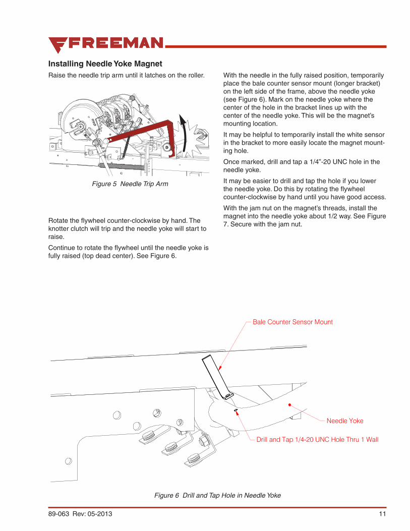
Installing Needle Yoke MagnetRaise the needle trip arm until it latches on the roller. With the needle in the fully raised position, temporarily
place the bale counter sensor mount (longer bracket) on the left side of the frame, above the needle yoke (see Figure 6). Mark on the needle yoke where the center of the hole in the bracket lines up with the center of the needle yoke. This will be the magnet’s mounting location.
It may be helpful to temporarily install the white sensor in the bracket to more easily locate the magnet mount-ing hole.
Once marked, drill and tap a 1/4”-20 UNC hole in the needle yoke.
It may be easier to drill and tap the hole if you lower the needle yoke. Do this by rotating the flywheel counter-clockwise by hand until you have good access.
With the jam nut on the magnet’s threads, install the magnet into the needle yoke about 1/2 way. See Figure 7. Secure with the jam nut.
Bale Counter Sensor Mount
Drill and Tap 1/4-20 UNC Hole Thru 1 Wall
Needle Yoke
Figure 5 Needle Trip Arm
Rotate the flywheel counter-clockwise by hand. The knotter clutch will trip and the needle yoke will start to raise.
Continue to rotate the flywheel until the needle yoke is fully raised (top dead center). See Figure 6.
Figure 6 Drill and Tap Hole in Needle Yoke
12 89-063 Rev: 05-2013
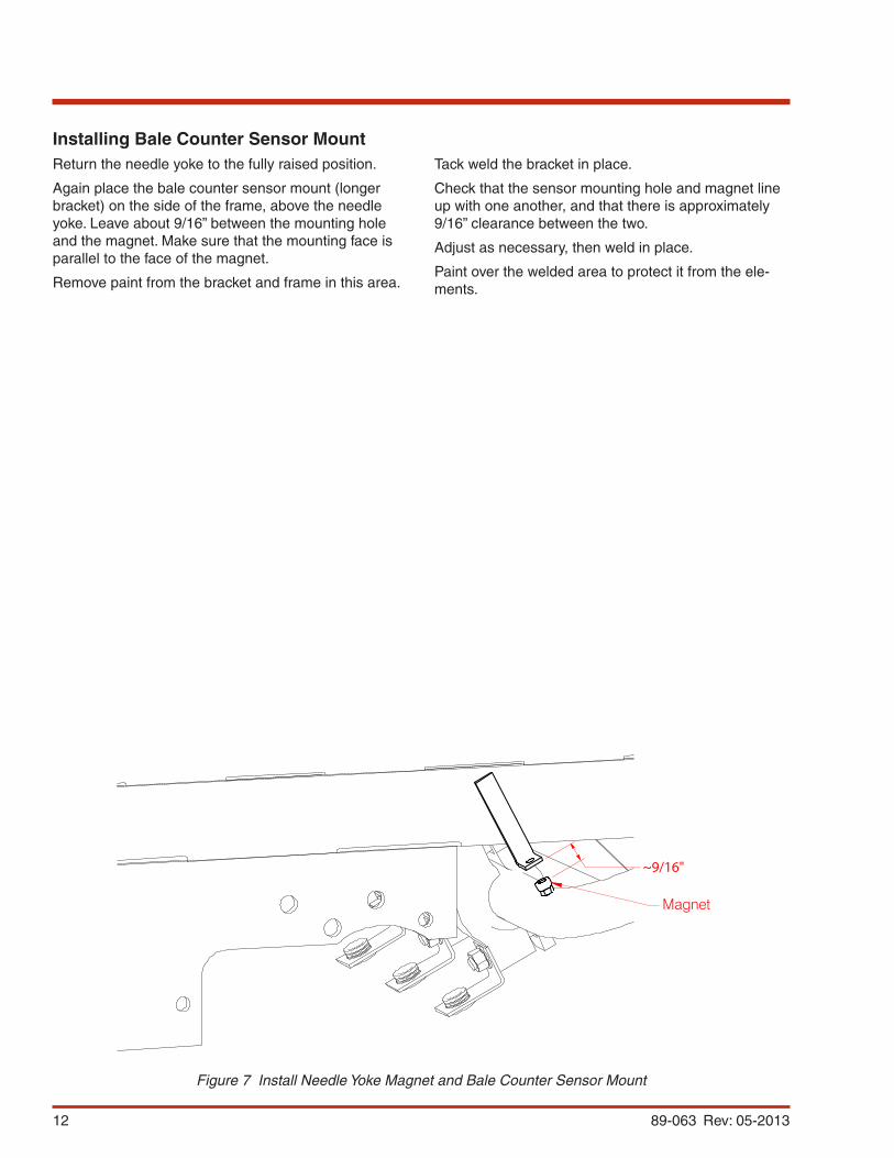
Installing Bale Counter Sensor MountReturn the needle yoke to the fully raised position.
Again place the bale counter sensor mount (longer bracket) on the side of the frame, above the needle yoke. Leave about 9/16” between the mounting hole and the magnet. Make sure that the mounting face is parallel to the face of the magnet.
Remove paint from the bracket and frame in this area.
~9/16"
Magnet
Figure 7 Install Needle Yoke Magnet and Bale Counter Sensor Mount
Tack weld the bracket in place.
Check that the sensor mounting hole and magnet line up with one another, and that there is approximately 9/16” clearance between the two.
Adjust as necessary, then weld in place.
Paint over the welded area to protect it from the ele-ments.

1389-063 Rev: 05-2013
Install & Adjust Plunger Magnet & SensorPlace the remaining magnet in the mount located on the plunger, with the magnet facing the outside of the plunger, and secure with the nut (see Figure 8).
Place the sensor with the blue wire (plunger sensor) in the plunger sensor mount.
Push the plunger as far to the left side of the chamber as possible. Adjust the sensor and/or magnet so that the gap between them is 1/4” - 3/8”.
Magnet
Sensor1/4” - 3/8”
Figure 8 Install Plunger Magnet and the Plunger Sensor (Blue Wire)
NOTICEBe mindful that as the wear pads on the plunger are worn over time, this gap could lessen. To reduce the chance of damage, check this gap periodically to ensure that there is a minimum of 1/4” gap when the plunger is pushed as far left as possible in the chamber. Readjust if necessary.
14 89-063 Rev: 05-2013
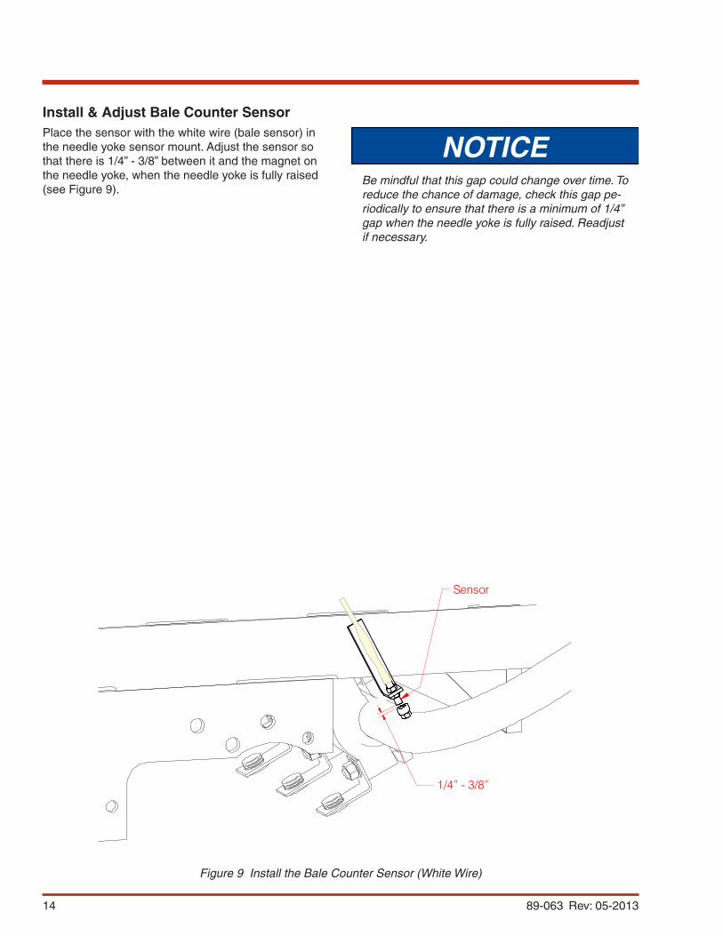
Install & Adjust Bale Counter SensorPlace the sensor with the white wire (bale sensor) in the needle yoke sensor mount. Adjust the sensor so that there is 1/4” - 3/8” between it and the magnet on the needle yoke, when the needle yoke is fully raised (see Figure 9).
Sensor
1/4” - 3/8”
Figure 9 Install the Bale Counter Sensor (White Wire)
NOTICEBe mindful that this gap could change over time. To reduce the chance of damage, check this gap pe-riodically to ensure that there is a minimum of 1/4” gap when the needle yoke is fully raised. Readjust if necessary.
1589-063 Rev: 05-2013
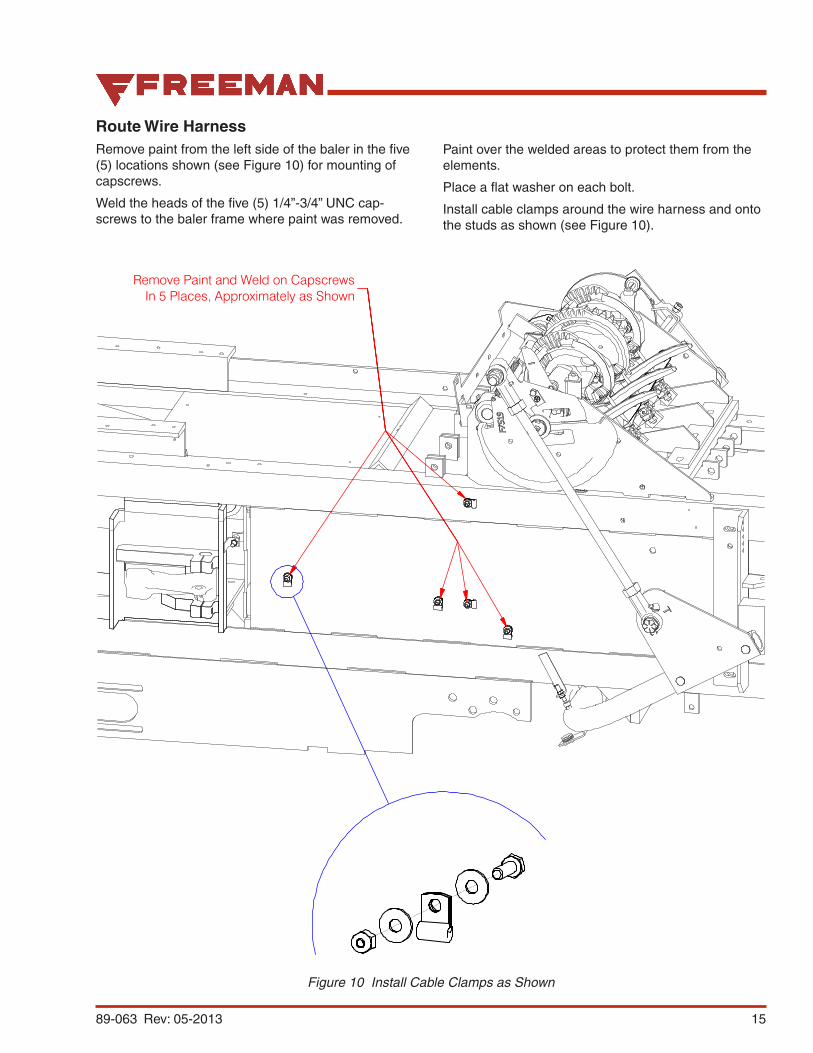
Route Wire HarnessRemove paint from the left side of the baler in the five (5) locations shown (see Figure 10) for mounting of capscrews.
Weld the heads of the five (5) 1/4”-3/4” UNC cap-screws to the baler frame where paint was removed.
Paint over the welded areas to protect them from the elements.
Place a flat washer on each bolt.
Install cable clamps around the wire harness and onto the studs as shown (see Figure 10).
Figure 10 Install Cable Clamps as Shown
Remove Paint and Weld on CapscrewsIn 5 Places, Approximately as Shown
16 89-063 Rev: 05-2013
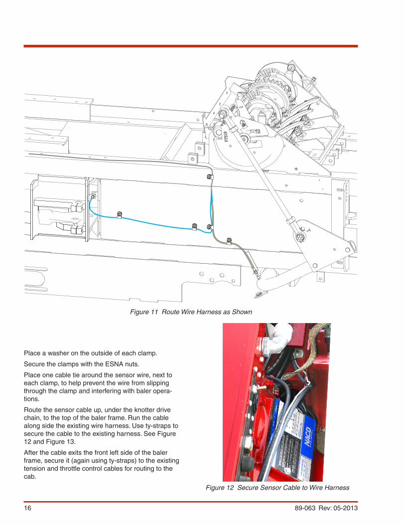
Figure 11 Route Wire Harness as Shown
Place a washer on the outside of each clamp.
Secure the clamps with the ESNA nuts.
Place one cable tie around the sensor wire, next to each clamp, to help prevent the wire from slipping through the clamp and interfering with baler opera-tions.
Route the sensor cable up, under the knotter drive chain, to the top of the baler frame. Run the cable along side the existing wire harness. Use ty-straps to secure the cable to the existing harness. See Figure 12 and Figure 13.
After the cable exits the front left side of the baler frame, secure it (again using ty-straps) to the existing tension and throttle control cables for routing to the cab.
Figure 12 Secure Sensor Cable to Wire Harness

1789-063 Rev: 05-2013
Figure 13 Route Sensor Cable to the Cab
18 89-063 Rev: 05-2013
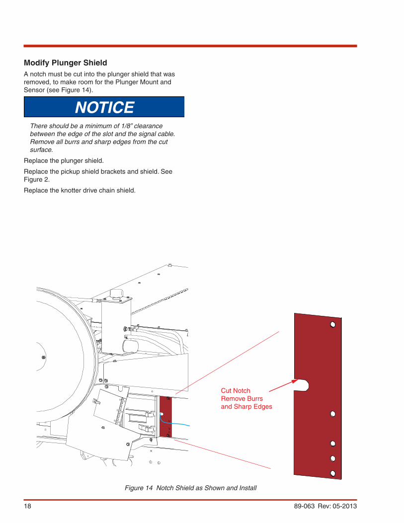
Modify Plunger ShieldA notch must be cut into the plunger shield that was removed, to make room for the Plunger Mount and Sensor (see Figure 14).
NOTICEThere should be a minimum of 1/8” clearance between the edge of the slot and the signal cable. Remove all burrs and sharp edges from the cut surface.
Replace the plunger shield.
Replace the pickup shield brackets and shield. See Figure 2.
Replace the knotter drive chain shield.
Figure 14 Notch Shield as Shown and Install
Cut NotchRemove Burrsand Sharp Edges
1989-063 Rev: 05-2013
Prepare Display
CAUTIONOnly qualified personnel should make the elec-trical connections described in this section.
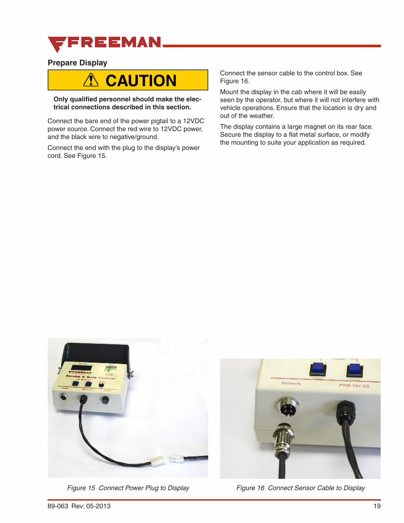
Connect the bare end of the power pigtail to a 12VDC power source. Connect the red wire to 12VDC power, and the black wire to negative/ground.
Connect the end with the plug to the display’s power cord. See Figure 15.
Connect the sensor cable to the control box. See Figure 16.
Mount the display in the cab where it will be easily seen by the operator, but where it will not interfere with vehicle operations. Ensure that the location is dry and out of the weather.
The display contains a large magnet on its rear face. Secure the display to a flat metal surface, or modify the mounting to suite your application as required.
Figure 15 Connect Power Plug to Display Figure 16 Connect Sensor Cable to Display

20 89-063 Rev: 05-2013
Operation
321
Figure 17 Operation
Once installed and connected, operation of your Stroke and Bale Counter is simple. There are three buttons.
1. Total. Press this button to reset the number shown in the Total Bales display to zero (0). Once at zero, the Total Bales display will increment by one for each bale that is tied.
2. Stroke. Press this button to reset the number shown in the Stroke display to zero (0). Under normal operation, the Stroke display will display the total number of plunger strokes to form the last bale that was tied. This effectively gives you the number of flakes for the previous bale.
3. Display On/Off. This button toggles the display power on and off. Make sure that the display is connected properly to a 12VDC power source.
At the beginning of a Baling session, press the Display On/Off button to turn the display on, then reset both the bale count and the stroke count, since values from the previous session will still be displayed (they are maintained in memory).
Note: The stroke count is counted between tie cycles. The stroke count for the first bale of every windrow will likely be too high, since the plunger is active even when the baler is not taking in mate-rial.

2189-063 Rev: 05-2013
Parts2.1 2.2
2.3 2.4
4 3
68 5 9 7
Item Part No. Qty Description Item Part No. Qty Description
906867 Kit - Stroke & Bale Counter 1 89-063 1 . Bale & Stroke Counter Manual 2 906801 1 . Bale Counter Assembly 2.1 906802 1 . . Display, Bale Counter 247710 1 . . . Fuse, 1 Amp 2.2 906836 1 . . Cable, Power 2.3 906837 1 . . Cable, Signal 2.4 906838 2 . . Magnet
3 906863 2 . Plate, Mounting 4 906864 1 . Plate, Mounting 5 R13803022 5 . Clip, Insulated 6 242601 15 . Cable Tie 7 15113W 5 . Nut 8 18460W 5 . Capscrew 9 15127W 10 . Washer


![Contents€¦ · .063 Inch [1.59mm] O.D. VINL-063 CLMP-063 TFLN-063 or NYLN-063 NYCLMP-063.125 Inch [3.18mm] O.D. VINL-125 CLMP-125 TFLN-125 NYLN-125HW NYCLMP-125 NYCLMP-125HW Pipe](https://img.pdfslide.us/doc/110x75/6008af2d53ec7b6e9042b7c5/contents-063-inch-159mm-od-vinl-063-clmp-063-tfln-063-or-nyln-063-nyclmp-063125.jpg)