Embed Size (px)
Citation preview

BernardAn Illinois Tool Works Company 449 West Corning Road, Box 667 Beecher, Illinois 60401 USA
Issued Nov. 2012 • Index No. OPMAN-1.3
Operations ManualQ-Gun™ and S-Gun™ Series MIG Guns
USAMade withPride and without
Compromise in the
All Guns are Not Created Equal.A MIG gun should be durable, easy to use and customized to your specific application. Our MIG guns put you in control: you choose the options you need and we'll build a gun to last. We even ship most of our guns within 24 hours.
Amperage ratings at 100% duty cycle with CO2 gas: 150, 200, 300, 400, 500 and 600 amps.
Power cables available with high flex standard or steel monocoil conduits and in lengths to fit any application.
Multiple lightweight, comfortable handle and easy-to-change trigger options allow guns to be performance matched to user preference.
Necks available in fixed, rotatable and numer-ous length options to improve operator comfort.
Contact tip options include CenterfireTM, Elliptical and Quik TipTM and are available in wire sizes from .023" (0.6 mm) to 1/8" (3.2 mm).
Direct plugs and trigger leads connect to wire feeders and machines from all major manu-facturers and are easily interchangeable to allow simple maintenance.
Phone: 800-946-2281 (US Only) 708-946-2281 (Outside US)
Fax: 708-946-6726For more information, visit us at BernardWelds.com
400 Amp Q-Gun MIG Gun with curved handle, medium 45˚ rotating neck and standard trigger.
300 Amp S-Gun MIG Gun with OXO™ style small curved handle, medium 45˚ rotating neck and standard trigger.
See BernardWelds.com Technical Support Section
for detailed specs and replacement parts information.
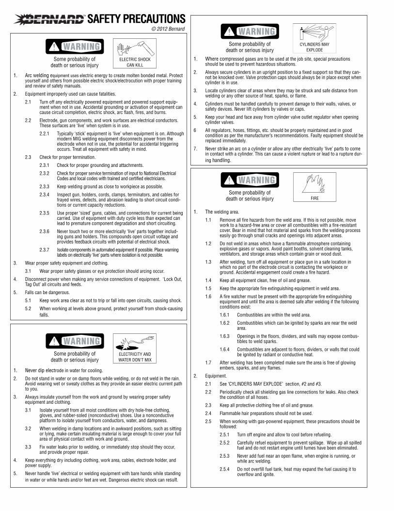
1. Where compressed gases are to be used at the job site, special precautions should be used to prevent hazardous situations.
2. Always secure cylinders in an upright position to a fixed support so that they can-not be knocked over. Valve protection caps should always be in place except when cylinder is in use.
3. Locate cylinders clear of areas where they may be struck and safe distance from welding or any other source of heat, sparks, or flame.
4. Cylinders must be handled carefully to prevent damage to their walls, valves, or safety devices. Never lift cylinders by valves or caps.
5. Keep your head and face away from cylinder valve outlet regulator when opening cylinder valves.
6 All regulators, hoses, fittings, etc. should be properly maintained and in good condition as per the manufacturer’s recommendations. Faulty equipment should be replaced immediately.
7. Never strike an arc on a cylinder or allow any other electrically ‘live’ parts to come in contact with a cylinder. This can cause a violent rupture or lead to a rupture dur-ing handling.
1. The welding area.
1.1 Remove all fire hazards from the weld area. If this is not possible, move work to a hazard-free area or cover all combustibles with a fire-resistant cover. Bear in mind that hot material and sparks from the welding process easily go through small cracks and openings into adjacent areas.
1.2 Do not weld in areas which have a flammable atmosphere containing explosive gases or vapors. Avoid paint booths, solvent cleaning tanks, ventilators, and storage areas which contain grain or wood dust.
1.3 After welding, turn off all equipment or place gun in a safe location in which no part of the electrode circuit is contacting the workpiece or ground. Accidental engagement could create a fire hazard.
1.4 Keep all equipment clean, free of oil and grease.
1.5 Keep the appropriate fire extinguishing equipment in weld area.
1.6 A fire watcher must be present with the appropriate fire extinguishing equipment and until the area is deemed safe after welding if the following conditions exist:
1.6.1 Combustibles are within the weld area.
1.6.2 Combustibles which can be ignited by sparks are near the weld area.
1.6.3 Openings in the floors, dividers, and walls may expose combus-tibles to weld sparks.
1.6.4 Combustibles are adjacent to floors, dividers, or walls that could be ignited by radiant or conductive heat.
1.7 After welding has been completed make sure the area is free of glowing embers, sparks, and any flames.
2. Equipment.
2.1 See ‘CYLINDERS MAY EXPLODE’ section, #2 and #3.
2.2 Periodically check all shielding gas line connections for leaks. Also check the condition of all hoses.
2.3 Keep all protective clothing free of oil and grease.
2.4 Flammable hair preparations should not be used.
2.5 When working with gas-powered equipment, these precautions should be followed:
2.5.1 Turn off engine and allow to cool before refueling.
2.5.2 Carefully refuel equipment to prevent spillage. Wipe up all spilled fuel and do not restart engine until fumes have been eliminated.
2.5.3 Never add fuel near an open flame, when engine is running, or while arc welding.
2.5.4 Do not overfill fuel tank, heat may expand the fuel causing it to overflow and ignite.
1. Arc welding equipment uses electric energy to create molten bonded metal. Protect yourself and others from possible electric shock/electrocution with proper training and review of safety manuals.
2. Equipment improperly used can cause fatalities.
2.1 Turn off any electrically powered equipment and powered support equip-ment when not in use. Accidental grounding or activation of equipment can cause circuit completion, electric shock, arc flash, fires, and burns.
2.2 Electrode, gun components, and work surfaces are electrical conductors. These surfaces are ‘live’ when system is in use.
2.2.1 Typically ‘stick’ equipment is ‘live’ when equipment is on. Although modern MIG welding equipment disconnects power from the electrode when not in use, the potential for accidental triggering occurs. Treat all equipment with safety in mind.
2.3 Check for proper termination.
2.3.1 Check for proper grounding and attachments.
2.3.2 Check for proper service termination of input to National Electrical Codes and local codes with trained and certified electricians.
2.3.3 Keep welding ground as close to workpiece as possible.
2.3.4 Inspect gun, holders, cords, clamps, terminators, and cables for frayed wires, defects, and abrasion leading to short circuit condi-tions or current capacity reductions.
2.3.5 Use proper ‘sized’ guns, cables, and connections for current being carried. Use of equipment with duty cycle less than expected can lead to premature component degradation and short circuiting.
2.3.6 Never touch two or more electrically ‘live’ parts together includ-ing guns and holders. This compounds open circuit voltage and provides feedback circuits with potential of electrical shock.
2.3.7 Isolate components in automated equipment if possible. Place warning labels on electrically ‘live’ parts where isolation is not possible.
3. Wear proper safety equipment and clothing.
3.1 Wear proper safety glasses or eye protection should arcing occur.
4. Disconnect power when making any service connections of equipment. ‘Lock Out, Tag Out’ all circuits and feeds.
5. Falls can be dangerous.
5.1 Keep work area clear as not to trip or fall into open circuits, causing shock.
5.2 When working at levels above ground, protect yourself from shock-causing falls.
1. Never dip electrode in water for cooling.
2. Do not stand in water or on damp floors while welding, or do not weld in the rain. Avoid wearing wet or sweaty clothes as they provide an easier electric current path to you.
3. Always insulate yourself from the work and ground by wearing proper safety equipment and clothing.
3.1 Isolate yourself from all moist conditions with dry hole-free clothing, gloves, and rubber-soled (nonconductive) shoes. Use a nonconductive platform to isolate yourself from conductors, water, and dampness.
3.2 When welding in damp locations and in awkward positions, such as sitting or lying, make certain insulating material is large enough to cover your full area of physical contact with work and ground.
3.3 Fix water leaks prior to welding, or immediately stop should they occur, and provide proper repair.
4. Keep everything dry including clothing, work area, cables, electrode holder, and power supply.
5. Never handle ‘live’ electrical or welding equipment with bare hands while standing in water or while hands and/or feet are wet. Dangerous electric shock can result.
SAFETY PRECAUTIONS © 2012 Bernard
ELECTRIC SHOCKCAN KILL
ELECTRICITY ANDWATER DON'T MIX
Some probability ofdeath or serious injury
Some probability ofdeath or serious injury
Some probability ofdeath or serious injury
CYLINDERS MAYEXPLODE
Some probability ofdeath or serious injury FIRE
3. Wear suitable clothing to reduce risk of burns to exposed skin.3.1 Wear durable, flame-resistant clothing with closed, opaque weaves. This
reduces chance of ‘sun’ burn, contact burns, and accidental ignition of clothing that could occur.
3.1.1 Do not wear wet or damp clothing.
3.2 Wear appropriate gloves, shoes, and outer protection as described to prevent electrical shock.
4. Protect others from arc rays that can burn unintentionally.4.1 Provide suitable screening to reduce exposure of others to existing weld-
ing areas.
4.2 Provide proper eye protection.
4.3 Provide suitable clothing.
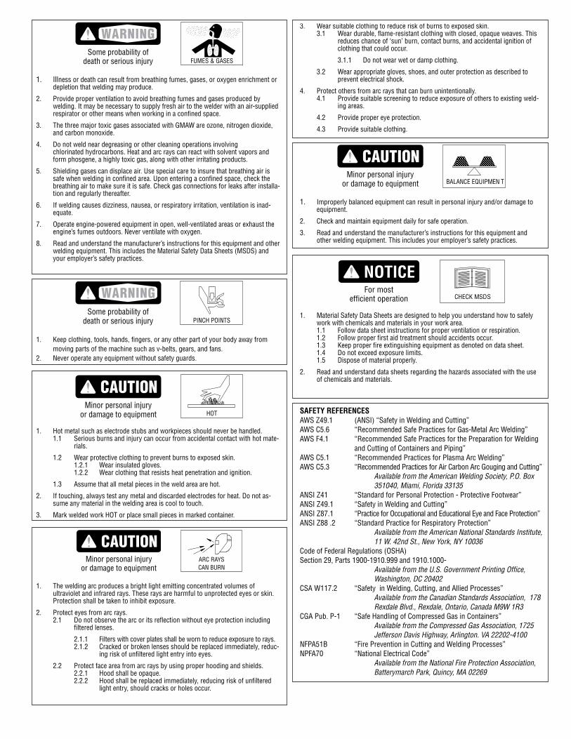
BALANCE EQUIPMEN TMinor personal injury
or damage to equipment
1. Improperly balanced equipment can result in personal injury and/or damage to equipment.
2. Check and maintain equipment daily for safe operation.
3. Read and understand the manufacturer’s instructions for this equipment and other welding equipment. This includes your employer’s safety practices.
CHECK MSDSFor most
efficient operation
1. Material Safety Data Sheets are designed to help you understand how to safely work with chemicals and materials in your work area.1.1 Follow data sheet instructions for proper ventilation or respiration.1.2 Follow proper first aid treatment should accidents occur.1.3 Keep proper fire extinguishing equipment as denoted on data sheet.1.4 Do not exceed exposure limits.1.5 Dispose of material properly.
2. Read and understand data sheets regarding the hazards associated with the use of chemicals and materials.
SAFETY REFERENCESAWS Z49.1 (ANSI) “Safety in Welding and Cutting”AWS C5.6 “Recommended Safe Practices for Gas-Metal Arc Welding”AWS F4.1 “Recommended Safe Practices for the Preparation for Welding
and Cutting of Containers and Piping”AWS C5.1 “Recommended Practices for Plasma Arc Welding”AWS C5.3 “Recommended Practices for Air Carbon Arc Gouging and Cutting” Available from the American Welding Society, P.O. Box
351040, Miami, Florida 33135ANSI Z41 “Standard for Personal Protection - Protective Footwear”ANSI Z49.1 “Safety in Welding and Cutting”ANSI Z87.1 “Practice for Occupational and Educational Eye and Face Protection”ANSI Z88 .2 “Standard Practice for Respiratory Protection” Available from the American National Standards Institute,
11 W. 42nd St., New York, NY 10036Code of Federal Regulations (OSHA)Section 29, Parts 1900-1910.999 and 1910.1000- Available from the U.S. Government Printing Office,
Washington, DC 20402CSA W117.2 “Safety in Welding, Cutting, and Allied Processes” Available from the Canadian Standards Association, 178
Rexdale Blvd., Rexdale, Ontario, Canada M9W 1R3CGA Pub. P-1 “Safe Handling of Compressed Gas in Containers” Available from the Compressed Gas Association, 1725
Jefferson Davis Highway, Arlington. VA 22202-4100NFPA51B “Fire Prevention in Cutting and Welding Processes”NPFA70 “National Electrical Code” Available from the National Fire Protection Association,
Batterymarch Park, Quincy, MA 02269
FUMES & GASESSome probability of
death or serious injury
1. Illness or death can result from breathing fumes, gases, or oxygen enrichment or depletion that welding may produce.
2. Provide proper ventilation to avoid breathing fumes and gases produced by welding. It may be necessary to supply fresh air to the welder with an air-supplied respirator or other means when working in a confined space.
3. The three major toxic gases associated with GMAW are ozone, nitrogen dioxide, and carbon monoxide.
4. Do not weld near degreasing or other cleaning operations involving chlorinated hydrocarbons. Heat and arc rays can react with solvent vapors and form phosgene, a highly toxic gas, along with other irritating products.
5. Shielding gases can displace air. Use special care to insure that breathing air is safe when welding in confined area. Upon entering a confined space, check the breathing air to make sure it is safe. Check gas connections for leaks after installa-tion and regularly thereafter.
6. If welding causes dizziness, nausea, or respiratory irritation, ventilation is inad-equate.
7. Operate engine-powered equipment in open, well-ventilated areas or exhaust the engine’s fumes outdoors. Never ventilate with oxygen.
8. Read and understand the manufacturer’s instructions for this equipment and other welding equipment. This includes the Material Safety Data Sheets (MSDS) and your employer’s safety practices.
PINCH POINTSSome probability of
death or serious injury
1. Keep clothing, tools, hands, fingers, or any other part of your body away from moving parts of the machine such as v-belts, gears, and fans.
2. Never operate any equipment without safety guards.
HOTMinor personal injury
or damage to equipment
1. Hot metal such as electrode stubs and workpieces should never be handled.1.1 Serious burns and injury can occur from accidental contact with hot mate-
rials.
1.2 Wear protective clothing to prevent burns to exposed skin. 1.2.1 Wear insulated gloves.1.2.2 Wear clothing that resists heat penetration and ignition.
1.3 Assume that all metal pieces in the weld area are hot.
2. If touching, always test any metal and discarded electrodes for heat. Do not as-sume any material in the welding area is cool to touch.
3. Mark welded work HOT or place small pieces in marked container.
1. The welding arc produces a bright light emitting concentrated volumes of ultraviolet and infrared rays. These rays are harmful to unprotected eyes or skin. Protection shall be taken to inhibit exposure.
2. Protect eyes from arc rays.2.1 Do not observe the arc or its reflection without eye protection including
filtered lenses.
2.1.1 Filters with cover plates shall be worn to reduce exposure to rays.2.1.2 Cracked or broken lenses should be replaced immediate ly, reduc-
ing risk of unfiltered light entry into eyes.
2.2 Protect face area from arc rays by using proper hooding and shields.2.2.1 Hood shall be opaque.2.2.2 Hood shall be replaced immediately, reducing risk of unfiltered
light entry, should cracks or holes occur.
Minor personal injuryor damage to equipment
ARC RAYSCAN BURN
page 1
IntroductionThank you for choosing Bernard. The product you have purchased has been carefully assembled and factory tested prior to shipment. Should you experience problems with installation or performance, please refer to the “Troubleshooting Guide” in this manual.
Before installing, compare the equipment received against the invoice to verify that the shipment is complete and undamaged. It is the responsibility of the purchaser to file all claims of damage or loss that may have occurred during transit with the carrier.
The manual contains general information on the operation of this Bernard product. Before installing or operating any equipment, read and understand the information and safety precautions presented in this manual. Also, note the various data plates, labels, and tags attached to the product.
While every precaution has been taken to assure the accuracy of this manual, Bernard assumes no responsibility for errors or omissions. Bernard assumes no liability for damages resulting from the use of the information contained herein. Bernard shall have no liability to the buyer for consequential damages or be liable to the in tort for any negligent manufacture of the goods or for the omissions of any warning therefrom.
Commercial WarrantyProduct is warranted to be free from defects in material and workmanship for 180 days after the sale by an authorized Buyer.
Bernard reserves the right to repair, replace or refund the purchase price of non-conforming product. Product found not defective will be returned to the Buyer after notification by Customer Service.
Bernard makes no other warranty of any kind, expressed or implied, including, but not limited to the warranties of merchantability or fitness for any purpose. Bernard shall not be liable under any circumstances to Buyer, or to any person who shall purchase from Buyer, for damages of any kind. Including, but not limited to any, direct, indirect incidental or consequential damages or loss of production or loss of profits resulting from any cause whatsoever, including, but not limited to, any delay, act, error or omission of Bernard.
Genuine Bernard parts must be used for safety and performance reasons or the warranty becomes invalid. Warranty shall not apply if accident, abuse, or misuse damages a product, or if a product is modified in any way except by authorized Bernard personnel.
SAFETY PRECAUTIONS CONTINUED...
EMF InformationConsiderations About Welding And The Effects Of Low Frequency Electric And Magnetic Fields
Welding Current, as it flows through welding cables, will cause electronic magnetic fields. There has been and still is some concern about such fields. However, after examining more than 500 studies spanning 17 years of research, a special blue ribbon committee of the National Research Council concluded that: “The body of evidence, in the committee’s judgment, has not demonstrated that exposure to power frequency electric and magnetic fields is a human-health hazard.” However, studies are still going forth and evidence continues to be examined. Until the final conclusions of the research are reached, you may wish to minimize your exposure to electromagnetic fields when welding or cutting.
To reduce magnetic fields in the workplace, use the following procedures:
1. Keep cables close together by twisting or taping them.
2. Arrange cables to on side and away from the operator.
Part I General DescriptionThe Bernard Q-Gun and S-Gun are designed primarily for processing mild steel electrode under GMAW (Gas Metal Arc Welding), MIG (Metal Inert Gas), MAG (Metal Active Gas), FCAW (Flux Cored Arc Welding), and MOG (Metal without Gas).
The Q-Gun and S-Gun provide rapid neck interchangeability, typically during production processes. Neck may also be positioned on line within a 360 degree rotation. This position allows for movements between standard horizontal welding, overhead, and hard-to-reach side angles. The neck includes an optional Jump Liner system that effectively reduces costs associated with one-piece liner systems. Bernard is concerned about your higher productivity.
The Q-Gun and S-Gun meet or exceed NEMA (National Electrical Manufacturer’s Association) EW3 requirements for guns used in a wide variety of applications including aluminum, silicone bronze, and hard facing alloys to name a few. With Bernard’s flexibility, many applications can be accommodated with field installed options increasing performance and maneuverability.
3. Do not coil or drape cables around your body.
4. Keep Welding power source and cables as far away from operator as practical.
5. Connect work clamp to workpiece as close to the weld as possible.
About Pacemakers:
Pacemaker wearers consult your doctor first. If cleared by your doctor, then follow the above procedures as recommended.
California Proposition 65 WarningThis product contains chemicals, including lead, known to the state of California to cause cancer, and birth defects or other reproductive harm. Wash hands after use.
© 2012 Bernard
1. Your gun has been shipped with a specific feeder connector and sized for electrode as per the part number indicated on its package. Please inspect the received gun against this part number for accuracy.
2. Turn off power prior to any installation.
3. Fully extend gun and cable. Press liner fully into power pin.
4. Safely expose approximately 2" (51 mm) of electrode beyond feeder or adaptor block.
5a. Bernard Quick Disconnect If you have purchased a Bernard Quick Disconnect gun, it is necessary to connect this unit to an adaptor kit providing the shielding gas, control circuit, and arc power. If this is a new installation, install the adaptor kit as per the kit instructions. With the Bernard adaptor installed, perform the following:
Orient power pin and gas pin with the adaptor receptacle. Slide the electrode into the liner and push the power pin into the socket. Rotate the locking sleeve until the locking pins of adaptor drop into the receiver of locking sleeve. Continue to engage power pin while twisting locking sleeve to make con-nection. Shielding gas, control circuit, and power are now engaged.
5b. Direct Plug Connect the power pin of the direct plug gun by sliding the electrode into the liner and the power fitting into the drive housing of the feeder. Fully seat the unit in position and tighten into place as designated in the manufacturer’s instructions. On initial installations, a thin film of silicone lubricant will aid installation and prevent O-ring damage.
Attach control lead wires to the appropriate plug, terminals, or lead kit. Plug or wire into the control circuit of the feeder as designated in manufacturer’s instructions.
If a gas hose is provided, connect to the feeder’s solenoid circuit to deliver shielding gas to the arc. If no gas hose is provided, gas is delivered through the power pin. Refer to the manufacturer’s instructions for proper gas connection at the feeder block or solenoid.
6. Remove nozzle from gas diffuser.
7a. Centerfire™ Tip - Pull tip from gas diffuser. An unobstructed electrode path has now been established.
7b. Elliptical Tip - Remove tip with a 1/8-1/4 turn counterclock-wise while pulling. An unobstructed electrode path has now been established.
7c. Quik Tip™ - Remove tip with a 1/4 turn counterclockwise. An unobstructed electrode path has now been established.
8. Safely feed electrode through the gun and approximately 1" (25 mm) beyond gas diffuser.
9a. Centerfire Tip - Reinstall the tip over the electrode and lock into position by reinstalling the nozzle.
9b. Elliptical and Quik Tip - Reinstall the tip over the electrode locking in position with clockwise motion. Reinstall nozzle.
Welding current and duty cycle shall not exceed published specification of this product. If such conditions exist, product life and performance will be reduced.
Nozzles:1. If anti-spatter is used, do not coat nozzle insulator as this
may degrade insulating material.
2. Nozzle should be cleaned as often as possible. Spatter buildup can often lead to poor gas shielding or short circuit-ing between the contact tip and the nozzle.
3. Spatter should be removed with the proper tools designed for spatter removal.
4. In high temperature welding applications, heavy duty con-sumables are recommended.
Contact Tips, Gas Diffusers:1. Centerfire and Elliptical contact tips may be removed and
rotated in gas diffuser, providing additional wear surfaces and extending the service life of the product.
2. Electrical stickout of the elliptical contact tip can be altered by positioning the contact tip in the desired location of the gas diffuser and rotating clockwise locking in place.
3. Inspect nozzle for spatter adhesion, blocked gas ports, and carbonized contact surfaces. Clean as often as possible.
4 If anti-spatter is used, periodically check gas ports for block-age.
5. When using dual shield electrode, periodically check gas ports in for clogging caused by flux from within the elec-trode.
Cable:1. Periodically check torques of neck and end fittings. Loose
fittings can cause overheating and premature failure of the gun.
2. Sharp bends and loops in the cable should be avoided. Often the best solution is to suspend the wire feeder from a boom or trolley, thus eliminating a large number of bends and keeping the cable clear of hot weldments.
3. Do not immerse liner into solvents for cleaning; the liner may be periodically blown out with compressed air.
4. Avoid rough surfaces and sharp edges that can cause tears and nicks in cable jacket which can cause premature failure.
5. Periodically check all cables and ground connections.
6. Use anti-seize on all threaded connections.
Part III Helpful Operating Tips
Part II Installationpage 2
Disconnect gun from equipment, allow to cool, and remove electrode from liner before servicing.
Section 1. NozzleA. Removal
Threaded fit nozzle can be removed by turning in a counter-clockwise direction. Slip-on nozzle is a friction fit and can be removed with a twisting and pulling motion.
B. ServiceInspect nozzle for cracks and degradation of insulation. Clean the nozzle as often as possible to prevent spatter build-up which can lead to poor gas shielding or short cir-cuiting. Replace the nozzle when loose, worn, or producing erratic gas shield.
C. InstallationReplace threaded fit nozzle by threading in a clockwise direc-tion. Centerfire nozzle body is used to secure contact tip.
Replace slip-on nozzles with a pushing and twisting motion.
Section 2. Contact TipBernard has designed its contact tips to allow rapid installation and adjustment.
A. RemovalCut electrode and remove all burrs before removing tip.
Centerfire - Remove threaded fit nozzle by turning in a counterclockwise direction. Pull the Centerfire tip from gas diffuser.
Elliptical - Removed with a 1/8-1/4 turn counterclockwise
while pulling tip from gas diffuser.
Quik Tip - Remove with a 1/4 turn counterclockwise.
B. ServiceTo extend contact tip life, reface front of tip and clean the bore. Centerfire and Elliptical tips may be rotated in gas dif-fuser socket providing additional wear surface and extending the service life of the product.
C. InstallationCut electrode and remove all burrs before removing tip.
Centerfire - Slide tip over electrode into gas diffuser and replace threaded fit nozzle by threading in a clockwise direc-tion. Nozzle body is used to secure contact tip.
Elliptical - Slide tip over electrode into gas diffuser and lock with a 1/8-1/4 turn clockwise rotation.
Quik Tip - Slide tip over electrode into gas diffuser and lock with a 1/4 turn clockwise rotation.
Section 3. Gas DiffuserA. Removal
The gas diffuser may be removed with an appropriate wrench in a counterclockwise rotation.
B. ServiceInspect gas diffuser for spatter, blocked gas ports, and car-bonized surfaces. Clean as often as possible. Replace with new gas diffuser when wear prevents engagement of contact tip or nozzle.
C. InstallationFirmly secure gas diffuser with an appropriate wrench in a clockwise rotation, torque to 70 in-lbs. Install insulator cap onto neck.
Section 4. Neck A. Removal
Rotatable - Grasp lock nut and rotate counterclockwise, rota-tion will free neck from end fitting.
Fixed - Remove liner and hex nut insulator. Using a wrench,
Feeder:1. Check drive rolls for wear; be sure drive rolls and guide
tubes are clean and free of debris. Do not overtighten drive rolls; set as per manufacturer’s specifications.
2. Use clean, non-corroded electrode.
3. When installing or replacing electrode, you may: remove burrs from end of electrode, remove gas diffuser and tip, and/or straighten the first few inches of electrode.
End User Stocking Recommendations:Nozzles ...................................... 5 for every 1 gun in serviceTips ........................................... 30 for every 1 gun in serviceGas Diffusers ............................ 4 for every 1 gun in serviceTriggers ..................................... 1 for every 10 guns in serviceNecks ........................................ 1 for every 20 guns in serviceHandle Kits ................................ 1 for every 20 guns in serviceReplacement Cables .................. 1 for every 20 guns in serviceStrain Relief Kits ....................... 1 for every 20 guns in serviceAdaptor Kits .............................. Order as NecessaryDirect Plug Kits ......................... Order as Necessary
These stocking recommendations are only initial guidelines based on an 80 hour work period. You should work closely with your distributor to tailor a stocking program that suits your specific needs. Results will vary.
Part IV Maintenance and Repair
Part III Helpful Operating Tips (cont.)page 3
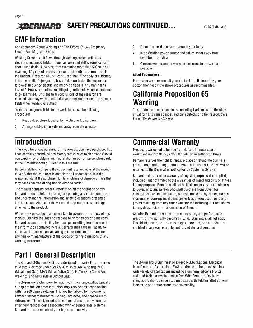
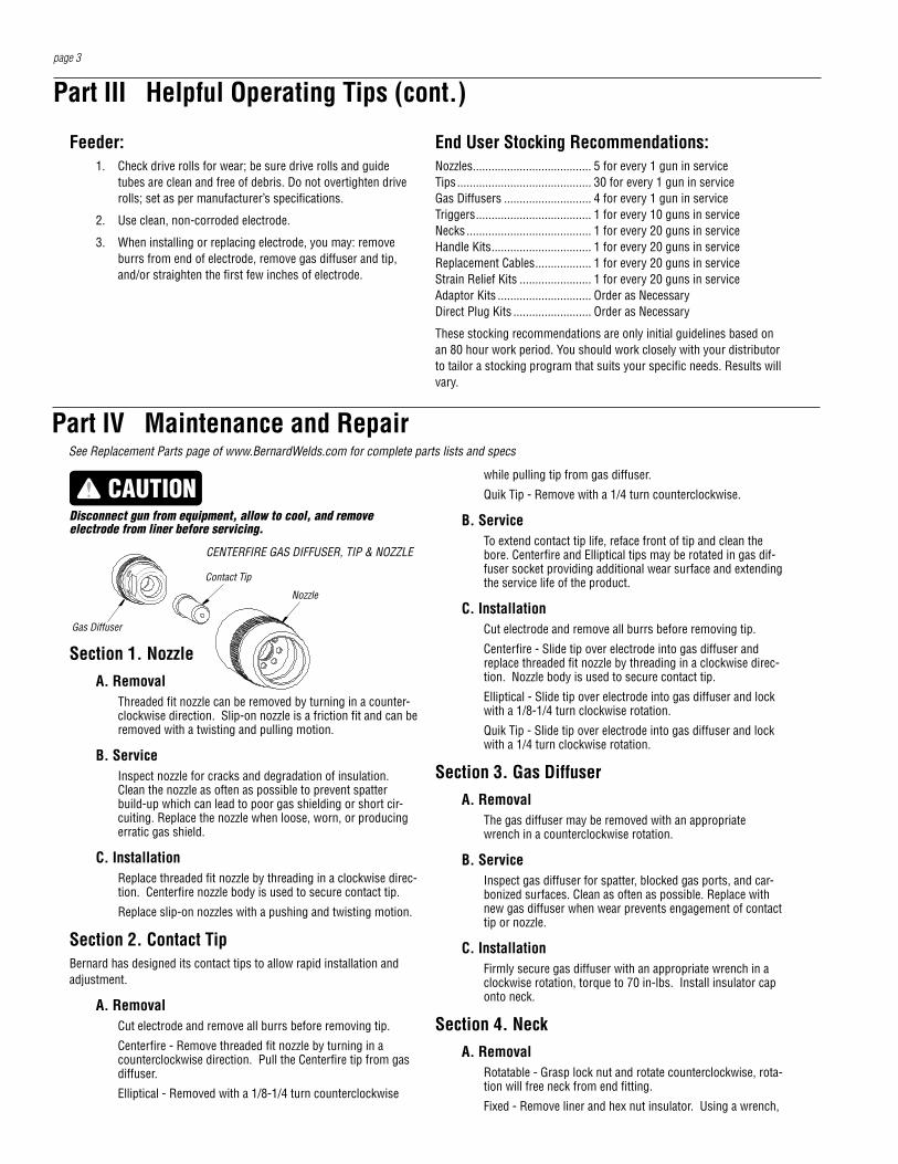
Gas Diffuser
Contact Tip
Nozzle
CENTERFIRE GAS DIFFUSER, TIP & NOZZLE
See Replacement Parts page of www.BernardWelds.com for complete parts lists and specs
ment of the trigger is not impaired. Reinstall post fasteners and screws; torque to 10 in-lbs (1.1 Nm)
Section 7. CableA. Inspection
Replace the cable assembly if the following conditions are evident on the exterior of the cable: cuts and/or abrasions in cable jacketing exposing copper stranding, abrupt kinking of cable causing abnormal heating in area of bend, loss of control circuit function as verified through continuity tests, slippage of insulating jacket exposing copper stranding, or crushed cable.
B. Replacement (excludes guns with OXO style handle)
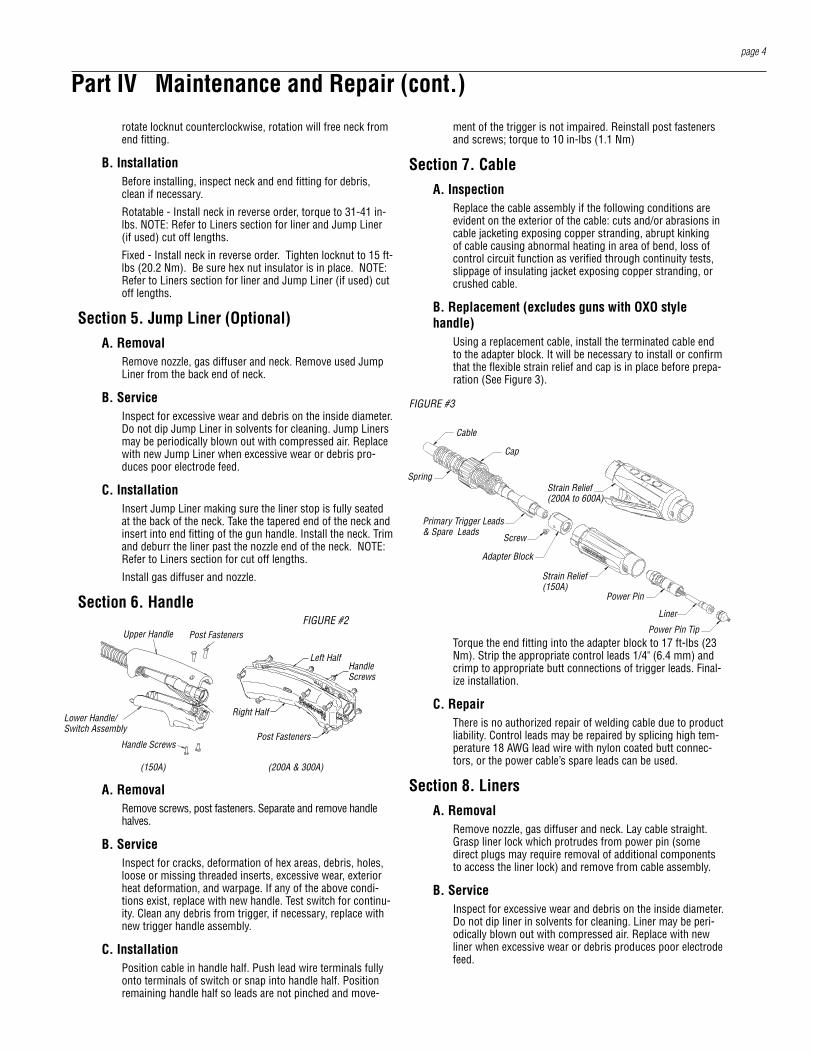
Using a replacement cable, install the terminated cable end to the adapter block. It will be necessary to install or confirm that the flexible strain relief and cap is in place before prepa-ration (See Figure 3).
FIGURE #3
Torque the end fitting into the adapter block to 17 ft-lbs (23 Nm). Strip the appropriate control leads 1/4" (6.4 mm) and crimp to appropriate butt connections of trigger leads. Final-ize installation.
C. RepairThere is no authorized repair of welding cable due to product liability. Control leads may be repaired by splicing high tem-perature 18 AWG lead wire with nylon coated butt connec-tors, or the power cable’s spare leads can be used.
Section 8. LinersA. Removal
Remove nozzle, gas diffuser and neck. Lay cable straight. Grasp liner lock which protrudes from power pin (some direct plugs may require removal of additional components to access the liner lock) and remove from cable assembly.
B. ServiceInspect for excessive wear and debris on the inside diameter. Do not dip liner in solvents for cleaning. Liner may be peri-odically blown out with compressed air. Replace with new liner when excessive wear or debris produces poor electrode feed.
page 4
rotate locknut counterclockwise, rotation will free neck from end fitting.
B. InstallationBefore installing, inspect neck and end fitting for debris, clean if necessary.
Rotatable - Install neck in reverse order, torque to 31-41 in-lbs. NOTE: Refer to Liners section for liner and Jump Liner (if used) cut off lengths.
Fixed - Install neck in reverse order. Tighten locknut to 15 ft-lbs (20.2 Nm). Be sure hex nut insulator is in place. NOTE: Refer to Liners section for liner and Jump Liner (if used) cut off lengths.
Section 5. Jump Liner (Optional)A. Removal
Remove nozzle, gas diffuser and neck. Remove used Jump Liner from the back end of neck.
B. ServiceInspect for excessive wear and debris on the inside diameter. Do not dip Jump Liner in solvents for cleaning. Jump Liners may be periodically blown out with compressed air. Replace with new Jump Liner when excessive wear or debris pro-duces poor electrode feed.
C. InstallationInsert Jump Liner making sure the liner stop is fully seated at the back of the neck. Take the tapered end of the neck and insert into end fitting of the gun handle. Install the neck. Trim and deburr the liner past the nozzle end of the neck. NOTE: Refer to Liners section for cut off lengths.
Install gas diffuser and nozzle.
Section 6. Handle
(150A) (200A & 300A)
A. RemovalRemove screws, post fasteners. Separate and remove handle halves.
B. ServiceInspect for cracks, deformation of hex areas, debris, holes, loose or missing threaded inserts, excessive wear, exterior heat deformation, and warpage. If any of the above condi-tions exist, replace with new handle. Test switch for continu-ity. Clean any debris from trigger, if necessary, replace with new trigger handle assembly.
C. InstallationPosition cable in handle half. Push lead wire terminals fully onto terminals of switch or snap into handle half. Position remaining handle half so leads are not pinched and move-
Part IV Maintenance and Repair (cont.)
Upper Handle
Lower Handle/Switch Assembly
Post Fasteners
Handle Screws
FIGURE #2
Post Fasteners
HandleScrews
Left Half
Right Half
Cap
Cable
Primary Trigger Leads & Spare Leads
Spring
Strain Relief(150A)
Screw
Power Pin
Liner
Power Pin Tip
Adapter Block
Strain Relief(200A to 600A)
strain relief by using a counterclockwise motion to unseat cap and sleeve assembly. Unthread power pin from end fitting with appropriate wrenches in a counterclockwise rota-tion (See Figure 5).
Do not wrench or clamp on crimped cable connection, this will damage the power cable connection.
The gas pin may be disassembled by removing the small retaining ring and pulling the pin from the rigid strain relief.
B. ServiceTest contact pins for continuity when trigger is engaged. Inspect all components for cracks, debris, excessive wear, and breakage. Replace with new components if safety or performance of product is compromised.
C. InstallationThread power pin onto cable end fitting and torque to 17 ft-lbs (23 Nm) minimum.
Do not wrench or clamp on crimped cable connection, this will damage the power cable connection.
Install wire assemblies (2) into the two symmetrical holes on the back side of the rigid strain relief. Do not cross control wires from side to side.
Seat pins fully to resist removal force, failure to do so will cause intermittent function of the gun.
Slide the power pin into the back of the rigid strain relief; when fully seated, the retaining ring groove in the power pin will be visible. Install the medium external snap ring into groove of power pin with external snap ring pliers.
Proper installation is critical to gun function; failure to do so will result in blockage of shielding gas.
Install rigid strain relief sleeve assembly and use a clockwise motion to seat cap.
Position wave spring and large internal snap ring in opening access slot (See Figure 4). With internal snap ring pliers inserted through locking sleeve, compress snap ring and slide sleeve into place. Snap ring must be fully seated in locking sleeve.
Failure to do so will cause intermittent function of the gun.
Locking sleeve must be able to rotate freely around rigid strain relief (See Figure 5). Install liner (Section 8).
page 5
Part IV Maintenance and Repair (cont.)C. Installation
Insert liner into power pin with cable laying straight. Con-tinue until liner lock is fully seated into power pin. A twisting motion may be necessary to seat O-ring (some direct plugs may require installation of additional components to secure liner).
Making sure cable is straight, trim and deburr liner at the nozzle end of neck as directed below.
Centerfire gas diffusers - Between 5/8" and 3/4" (1.6 - 1.9 cm)Elliptical gas diffusers (4235 and 4635) - 3/8" (9.5 mm)
Elliptical gas diffusers (4335 and 4435) - 1-3/8" (3.5 cm)Quik Tip gas diffusers (D118Q) - 7/8" (2.2 cm)Quik Tip gas diffusers (D114Q) - 3/4" (1.9 cm)When using Jump Liner: Trim and deburr liner with 1/4" (6.4 mm) extending beyond the gun handle. Install neck.
Install gas diffuser and nozzle.
Section 9. Rigid Strain ReliefA. Removal
Using a counterclockwise motion, unseat cap and sleeve assembly from rigid strain relief. Remove screw securing strain relief to adapter block.
B. ServiceInspect all components for cracks, debris, excessive wear and breakage. Replace with new components if safety or performance of product is compromised.
C. InstallationAlign flats in rigid strain relief with flats on adapter block. Slide strain relief onto adapter block and install screw. Torque screw to 12 in-lbs (1.4 Nm). Using the arrows on the cap to align with mating grooves, slide the cap and sleeve assembly toward the rigid strain relief until seated, and turn clockwise until engaging snap is felt.
Section 10a. Bernard Quick Disconnect Gun Connection
A. RemovalRemove liner from gun assembly (Section 8). Viewing quick disconnect from cable end, align wave spring and large snap ring with opening access slot (See Figure 4).
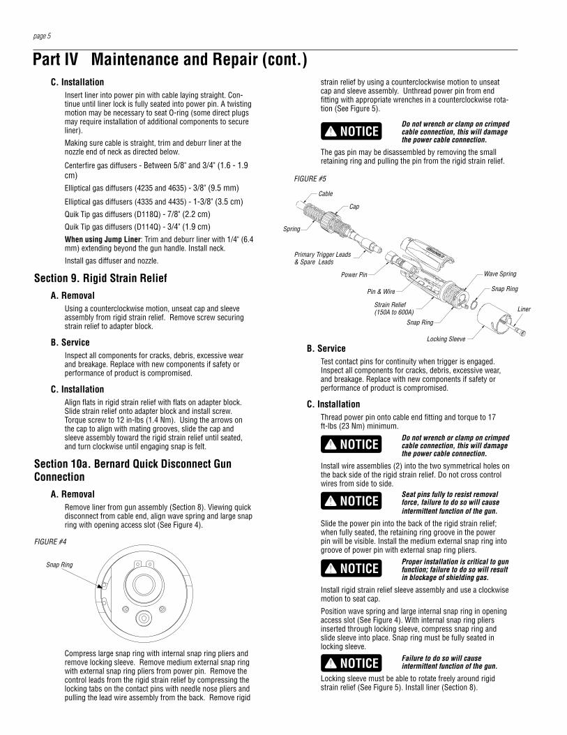
FIGURE #4
Compress large snap ring with internal snap ring pliers and remove locking sleeve. Remove medium external snap ring with external snap ring pliers from power pin. Remove the control leads from the rigid strain relief by compressing the locking tabs on the contact pins with needle nose pliers and pulling the lead wire assembly from the back. Remove rigid
Snap Ring
FIGURE #5
Spring
Cable
Cap
Primary Trigger Leads & Spare Leads
Power Pin
Pin & Wire
Strain Relief(150A to 600A)
Snap Ring
Locking Sleeve
Wave Spring
Snap Ring
Liner
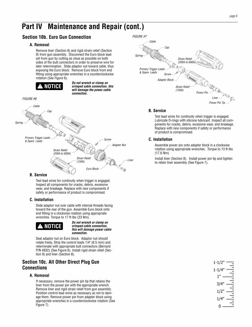
Section 10b. Euro Gun ConnectionA. Removal
Remove liner (Section 8) and rigid strain relief (Section 9) from gun assembly. Disconnect the Euro block lead set from gun by cutting as close as possible on both sides of the butt connectors in order to preserve wire for later retermination. Slide adaptor nut toward cable, thus exposing the Euro block. Remove Euro block from end fitting using appropriate wrenches in a counterclockwise rotation (See Figure 6).
Do not wrench or clamp on crimped cable connection, this will damage the power cable connection.
B. ServiceTest lead wires for continuity when trigger is engaged. Inspect all components for cracks, debris, excessive wear, and breakage. Replace with new components if safety or performance of product is compromised.
C. InstallationSlide adaptor nut over cable with internal threads facing toward the rear of the gun. Assemble Euro block onto end fitting in a clockwise rotation using appropriate wrenches. Torque to 17 ft-lbs (23 Nm).
Do not wrench or clamp on crimped cable connection, this will damage power cable connection.
Seat adaptor nut on Euro block. Adaptor nut should rotate freely, Strip the control leads 1/4" (6.5 mm) and reterminate with appropriate butt connectors (Bernard P/N 4932) (See Figure 6). Install rigid strain relief (Sec-tion 9) and liner (Section 8).
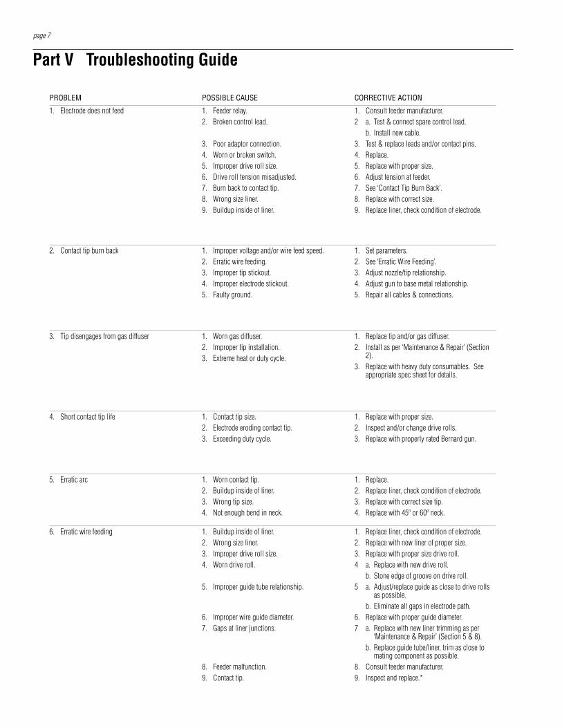
Section 10c. All Other Direct Plug Gun Connections
A. RemovalIf necessary, remove the power pin tip that retains the liner from the power pin with the appropriate wrench. Remove liner and rigid strain relief from gun assembly. Position control lead wires as necessary as not to dam-age them. Remove power pin from adapter block using appropriate wrenches in a counterclockwise rotation (See Figure 7).
page 6
Part IV Maintenance and Repair (cont.)FIGURE #7
Cap
Cable
Primary Trigger Leads & Spare Leads
Spring
Strain Relief(150A)
Screw
Power Pin
Liner
Power Pin Tip
Strain Relief(200A to 600A)
Adapter Block
B. ServiceTest lead wires for continuity when trigger is engaged. Lubricate O-rings with silicone lubricant. Inspect all com-ponents for cracks, debris, excessive wear, and breakage. Replace with new components if safety or performance of product is compromised.
C. InstallationAssemble power pin onto adapter block in a clockwise rotation using appropriate wrenches. Torque to 13 ft-lbs (17.6 Nm)
Install liner (Section 8). Install power pin tip and tighten to retain liner assembly (See Figure 7).
"4/1
"1
0
"2/1
"4/3
"4/1-1
"2/1-1
FIGURE #6
Spring
Cable
Cap
Primary Trigger Leads & Spare Leads
Strain Relief(200A to 600A)
Strain Relief(150A)
Adapter Nut
Screw
Liner
Euro Block
page 7
Part V Troubleshooting Guide
PROBLEM POSSIBLE CAUSE CORRECTIVE ACTION
1. Electrode does not feed 1. Feeder relay.2. Broken control lead.
3. Poor adaptor connection.4. Worn or broken switch.5. Improper drive roll size.6. Drive roll tension misadjusted.7. Burn back to contact tip.8. Wrong size liner.9. Buildup inside of liner.
1. Consult feeder manufacturer.2 a. Test & connect spare control lead.
b. Install new cable.3. Test & replace leads and/or contact pins.4. Replace.5. Replace with proper size.6. Adjust tension at feeder.7. See ‘Contact Tip Burn Back’.8. Replace with correct size.9. Replace liner, check condition of electrode.
2. Contact tip burn back 1. Improper voltage and/or wire feed speed.2. Erratic wire feeding.3. Improper tip stickout.4. Improper electrode stickout.5. Faulty ground.
1. Set parameters.2. See ‘Erratic Wire Feeding’.3. Adjust nozzle/tip relationship.4. Adjust gun to base metal relationship.5. Repair all cables & connections.
3. Tip disengages from gas diffuser 1. Worn gas diffuser.2. Improper tip installation.3. Extreme heat or duty cycle.
1. Replace tip and/or gas diffuser.2. Install as per ‘Maintenance & Repair’ (Section
2).3. Replace with heavy duty consumables. See
appropriate spec sheet for details.
5. Erratic arc 1. Worn contact tip.2. Buildup inside of liner.3. Wrong tip size.4. Not enough bend in neck.
1. Replace.2. Replace liner, check condition of electrode.3. Replace with correct size tip.4. Replace with 45º or 60º neck.
4. Short contact tip life 1. Contact tip size.2. Electrode eroding contact tip.3. Exceeding duty cycle.
1. Replace with proper size.2. Inspect and/or change drive rolls.3. Replace with properly rated Bernard gun.
6. Erratic wire feeding 1. Buildup inside of liner.2. Wrong size liner.3. Improper drive roll size.4. Worn drive roll.
5. Improper guide tube relationship.
6. Improper wire guide diameter.7. Gaps at liner junctions.
8. Feeder malfunction.9. Contact tip.
1. Replace liner, check condition of electrode.2. Replace with new liner of proper size.3. Replace with proper size drive roll.4 a. Replace with new drive roll.
b. Stone edge of groove on drive roll.5 a. Adjust/replace guide as close to drive rolls
as possible. b. Eliminate all gaps in electrode path.6. Replace with proper guide diameter.7 a. Replace with new liner trimming as per
‘Maintenance & Repair’ (Section 5 & 8).b. Replace guide tube/liner, trim as close to
mating component as possible.8. Consult feeder manufacturer.9. Inspect and replace.*
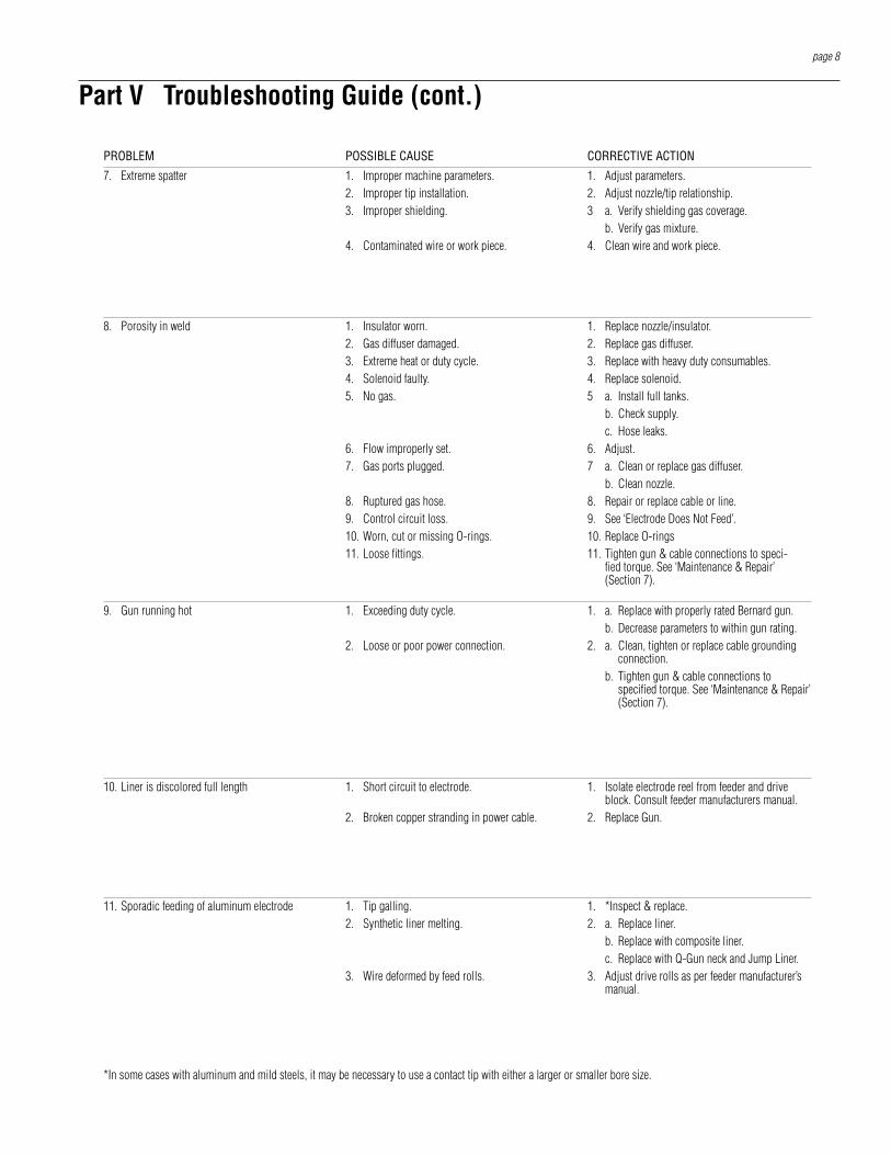
Part V Troubleshooting Guide (cont.)
*In some cases with aluminum and mild steels, it may be necessary to use a contact tip with either a larger or smaller bore size.
7. Extreme spatter 1. Improper machine parameters.2. Improper tip installation.3. Improper shielding.
4. Contaminated wire or work piece.
1. Adjust parameters.2. Adjust nozzle/tip relationship.3 a. Verify shielding gas coverage.
b. Verify gas mixture.4. Clean wire and work piece.
8. Porosity in weld 1. Insulator worn.2. Gas diffuser damaged.3. Extreme heat or duty cycle.4. Solenoid faulty.5. No gas.
6. Flow improperly set.7. Gas ports plugged.
8. Ruptured gas hose.9. Control circuit loss.10. Worn, cut or missing O-rings.11. Loose fittings.
1. Replace nozzle/insulator.2. Replace gas diffuser.3. Replace with heavy duty consumables.4. Replace solenoid.5 a. Install full tanks.
b. Check supply.c. Hose leaks.
6. Adjust.7 a. Clean or replace gas diffuser.
b. Clean nozzle.8. Repair or replace cable or line.9. See ‘Electrode Does Not Feed’.10. Replace O-rings11. Tighten gun & cable connections to speci-
fied torque. See ‘Maintenance & Repair’ (Section 7).
9. Gun running hot 1. Exceeding duty cycle.
2. Loose or poor power connection.
1. a. Replace with properly rated Bernard gun.b. Decrease parameters to within gun rating.
2. a. Clean, tighten or replace cable grounding connection.
b. Tighten gun & cable connections to specified torque. See ‘Maintenance & Repair’ (Section 7).
10. Liner is discolored full length 1. Short circuit to electrode.
2. Broken copper stranding in power cable.
1. Isolate electrode reel from feeder and drive block. Consult feeder manufacturers manual.
2. Replace Gun.
11. Sporadic feeding of aluminum electrode 1. Tip galling.2. Synthetic liner melting.
3. Wire deformed by feed rolls.
1. *Inspect & replace.2. a. Replace liner.
b. Replace with composite liner.c. Replace with Q-Gun neck and Jump Liner.
3. Adjust drive rolls as per feeder manufacturer’s manual.
PROBLEM POSSIBLE CAUSE CORRECTIVE ACTION
page 8

Notes
©2012 Bernard Printed in U.S.A.