Embed Size (px)
Citation preview
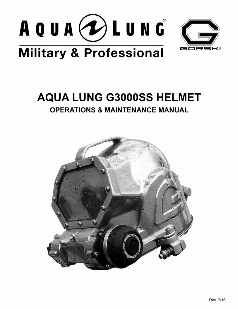
AQUA LUNG G3000SS HELMETOPERATIONS & MAINTENANCE MANUAL
Rev. 7/16

2 Aqua Lung G3000SS Diving Helmet Operations & Maintenance Manual
COPYRIGHT NOTICE
This manual is copyrighted, all rights reserved. It may not, in whole or in part, be copied, photocopied, reproduced, translated, or reduced to any electronic medium or machine readable form without prior consent in writing from Aqua Lung America, Inc. It may not be distributed through the internet or computer bulletin board systems without prior consent in writing from Aqua Lung America.
© 2016 AQUA LUNG AMERICA, INC. AQUA LUNG G3000SS DIVING HELMET OPERATIONS & MAINTENANCE MANUAL, PN 400179
Aqua Lung G3000SS Diving Helmet
PN 400300 Helmet Complete, G3000SSPN 400301 Helmet Complete, G3000SS w/ Hi - Use Connector
PN 400302 Helmet Complete, G3000SS w/ Marsh Marine Connector
You can contact a Technical Advisor via e-mail at:
[email protected]@aqualung.com
Trademark NoticeAqua Lung®, is a registered trademark of Aqua Lung America, Inc.
Warnings, Cautions and Notes:Pay special attention to information provided in warnings, cautions, and notes,
that is accompanied by these symbols:
A NOTE is used to emphasize important points, tips, and reminders.
A CAUTION indicates any situation or technique that could cause damage to the product, and could subsequently result in injury to the user.
A WARNING indicates a procedure or situation that if not avoided, could result in serious injury or death to the user.

3
TABLE OF CONTENTSI. SAFETY INFORMATION ....................................................................................................................................................6
Operator and Technician Training ................................................................................................................................6Recommended Air Supply Pressure ............................................................................................................................6Long Duration & Cold Water Diving .............................................................................................................................6
II. WARRANTY INFORMATION .............................................................................................................................................6
OPERATIONS SECTION III. HELMET OPERATING INFORMATION ...........................................................................................................................7
Helmet Description ........................................................................................................................................................7Performance & Certification .........................................................................................................................................7Dive System Requirements ...........................................................................................................................................8Bailout Configurations ..................................................................................................................................................9Helmet Set-Up Procedures .......................................................................................................................................... 11User Checklists ............................................................................................................................................................ 11Gas Supply Pressures ................................................................................................................................................. 11Gas Specifications ....................................................................................................................................................... 11Suit Inflation ................................................................................................................................................................. 11Use with Low Pressure Oxygen .................................................................................................................................12Noise Exposure ............................................................................................................................................................12Helmet Weight and Mass .............................................................................................................................................12Head Protection ...........................................................................................................................................................12Environmental Conditions ..........................................................................................................................................12G2000SS Helmet Conversion ......................................................................................................................................12
IV. USER CHECKLISTS ......................................................................................................................................................13CHECKLIST 1: G3000SS Diving Helmet Daily Checklist ..........................................................................................14CHECKLIST 2: G3000SS Diving Helmet Pre-Dive Checklist ....................................................................................18CHECKLIST 3: G3000SS Diving Helmet In-Water Checklist for Supervisor ...........................................................21CHECKLIST 4: G3000SS Diving Helmet Post-Dive Checklist ..................................................................................23
TECHNICAL SECTIONV. HELMET TECHNICAL INFORMATION ...........................................................................................................................26
Authorized Technicians ...............................................................................................................................................26Factory Prescribed Procedures ..................................................................................................................................26Scheduled Service .......................................................................................................................................................26Lubrication ...................................................................................................................................................................26Technician Checklists..................................................................................................................................................27General Guidelines ......................................................................................................................................................27
4 Aqua Lung G3000SS Diving Helmet Operations & Maintenance Manual
VI. STEP-BY-STEP DISASSEMBLY / ASSEMBLY INSTRUCTIONS .................................................................................28Notes on Disassembly and Reassembly ...................................................................................................................28Helmet Sub-Assemblies in this Section ....................................................................................................................28Tools Required for Annual Maintenance ...................................................................................................................28G3000SS Diving Helmet Disassembly Procedures ...................................................................................................29
Neck Dam and Quad Ring .....................................................................................................................................29Neck Retainer and Locking System .....................................................................................................................29Head Liner ..............................................................................................................................................................30Nose Clearing Device (NCD) .................................................................................................................................31Oral - Nasal Mask ...................................................................................................................................................31Communications ...................................................................................................................................................32Double Exhaust / Water Dump Valve ...................................................................................................................33Manifold ..................................................................................................................................................................34Airway .....................................................................................................................................................................35Second Stage Regulator .......................................................................................................................................35Defogger .................................................................................................................................................................36Free Flow / Water Dump Valve..............................................................................................................................36Face Port ................................................................................................................................................................38
G3000SS Diving Helmet Reassembly Procedures ....................................................................................................39Face Port ................................................................................................................................................................39Free Flow / Water Dump Valve..............................................................................................................................40Airway .....................................................................................................................................................................41Manifold ..................................................................................................................................................................41Double Exhaust / Water Dump Valve ...................................................................................................................42Defogger .................................................................................................................................................................44Second Stage Regulator .......................................................................................................................................44Nose Clearing Device (NCD) .................................................................................................................................44Oral - Nasal Mask ...................................................................................................................................................45Communications ...................................................................................................................................................45Head Liner ..............................................................................................................................................................46Neck Retainer and Locking System .....................................................................................................................47Neck Dam and Quad Ring .....................................................................................................................................47
VII. TECHNICIAN CHECKLISTS .........................................................................................................................................48
CHECKLIST 5: G3000SS Diving Helmet Monthly Inspection and Maintenance Checklist ....................................49CHECKLIST 6: G3000SS Diving Helmet Annual Inspection and Maintenance Checklist .....................................54
Part 1 - Helmet Disassembly ................................................................................................................................55Part 2 - Helmet Reassembly .................................................................................................................................62Part 3 - Helmet Final Testing ................................................................................................................................69
5
VIII. APPENDICES ............................................................................................................................................................... 72
A. Main Assemblies ..................................................................................................................................................... 73B. Inner Components ................................................................................................................................................... 74C. Manifold .................................................................................................................................................................... 75D. Free Flow / Water Dump Valve ............................................................................................................................... 76E. Second Stage Regulator ......................................................................................................................................... 77F. Nose Clearing Device (NCD) ................................................................................................................................... 78G. Neck Dam ................................................................................................................................................................. 79H. Welding Shield Kit ................................................................................................................................................... 80I. Welding Shield Assembly Installation Instructions ............................................................................................... 81J. Free Flow Plug Insert Kit Installation Instructions ............................................................................................... 82K. Camera / Light Bracket Installation Instructions .................................................................................................. 84L. Terminal Block Communications Kits ................................................................................................................... 85M. Twist-On Communications Kits ............................................................................................................................. 86N. Communications Kit Installation Instructions ...................................................................................................... 87O. Torque Specifications ............................................................................................................................................. 91P. Recommended Cleaners and Lubricants .............................................................................................................. 92Q. Cleaning and Lubricating ....................................................................................................................................... 93R. Annual Service Kit ................................................................................................................................................... 94S. Field Spares Kit ....................................................................................................................................................... 95T. Maintenance Log Sheet ........................................................................................................................................... 96
IX. G3000SS DIVING HELMET SPARE PARTS LIST ........................................................................................................ 97
X. G3000SS DIVING HELMET ACCESSORIES ............................................................................................................... 100
6 Aqua Lung G3000SS Diving Helmet Operations & Maintenance Manual
I. SAFETY INFORMATION
OPERATOR AND TECHNICIAN TRAININGThe G3000SS Diving Helmet should be used and operated by properly trained and certified divers and tenders only.The technical procedures in this manual are to be performed only by personnel who have received factory authorized training through an Aqua Lung Service & Repair Seminar.
RECOMMENDED AIR SUPPLY PRESSUREThe recommended air supply pressure is 129 - 326 PSI (8.9 - 22.5 BAR) Over Bottom Pressure as per the G3000SS Diving Helmet Regulated Supply Pressure Table in Checklist 3, In-Water Checklist for Supervisor.
LONG DURATION & COLD WATER DIVINGDiving for long durations and/or in cold water may subject the diver to severe body and respiratory heat loss. This may lead to a decrease in body core temperature also known as “hypothermia.” Hypothermia is an extremely dangerous condition and can lead to a loss of reasoning ability, decreased manual dexterity, uncontrollable shivering, unconsciousness, and death.
II. WARRANTY INFORMATION
The manufacturer warrants every new helmet to be free from defects in workmanship for a period of twelve (12) months from date of purchase.
Parts covered under the warranty:
• This warranty covers all metal parts.
Parts not covered under the warranty:
• This warranty does not cover any soft parts (e.g. o-rings, diaphragms), communications components, headliners, or chrome plating. Due to the electrolytic nature of underwater cutting and welding, chrome plating cannot be warranted when the diver engages in these activities.
The warranty becomes null and void if:
• The product has been modified without consent of Aqua Lung America, Inc.
• The product has been misused, damaged, put into a situation or service for which the product is not intended or if the product has not been correctly maintained according to the G3000SS Diving Helmet Operations & Maintenance Manual.
7
III. HELMET OPERATING INFORMATION
HELMET DESCRIPTIONThe G3000SS Diving Helmet is a high performance diving helmet for professional diving applications. The key features of the G3000SS include:
• Balanced design second stage regulator manufactured by Apeks.• High grade communications manufactured by OTS.• Stainless steel (316L) shell, neck retainer and neck ring: no dissimilar metals.• Breathing loop components protected inside shell.• Low component count and reduced maintenance load.• Optional modification kit for field conversion to free flow mode.
OPERATIONS SECTION
The G3000SS has a similar design to the original Gorski G2000SS helmet but with these upgrades:
• Apeks GX300 second stage regulator.• Double exhaust and double water dump protection.• Ergonomic free flow knob.• 4-wire communications (Marsh Marine or Hi-Use version).
PERFORMANCE AND CERTIFICATIONThe G3000SS Diving Helmet:
• Is suitable for use with standard compressed breathing air ("diving air"). See below.• Meets Work of Breathing (WOB) performance requirements at all required standard and high
Respiratory Minute Volume (RMV) work rates. • Meets inspired partial pressure of carbon dioxide performance requirements at all required
standard and high Respiratory Minute Volume (RMV) work rates. • Is tested and certified for use in water temperatures down to 4 degrees Celsius (39.2
degrees Fahrenheit).
The G3000SS Diving Helmet has been CE certified by DNV-GL, Det Norske Veritas-Germanischer Lloyd SE, Brooktorkai 18, 20457 Hamburg, Germany, Notified Body number 0098 and has been found to be in accordance with the requirements of EC Directive 89/686/EEC for Personal Protective Equipment (PPE). When examined the product satisfied the requirements of the manufacturer’s technical specifications (based upon EN 15333-1: 2008, Respiratory Equipment – Open-circuit umbilical supplied compressed gas diving apparatus requirements), which has been previously assessed and deemed to meet the basic health and safety requirements (Annex II) of the directive. The DNV GL Certificate Nos are 55594-14 HH, and 55594-14 HH Addition 1.
The CE certification for the G3000SS Diving Helmet includes the use of the Bailout Switch Block and the Helmet Side Block. See Bailout Configuration section below for further information.
CE certification of the Emergency Gas Supply (EGS) or bailout system includes the mandatory use of Apeks first stage regulators type FSR (XTX200), FST (XTX100), DST (XTX50), or DST.
The CE certificated depth of 50 m (165 ft) is a standard maximum certification depth for diving equipment that is used to provide a uniform benchmark for measuring performance. It is not an equipment depth limitation.
8 Aqua Lung G3000SS Diving Helmet Operations & Maintenance Manual
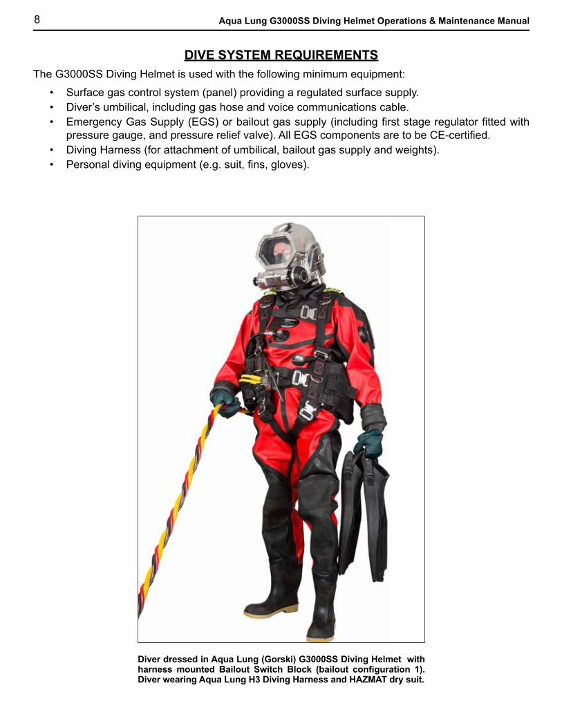
DIVE SYSTEM REQUIREMENTSThe G3000SS Diving Helmet is used with the following minimum equipment:
• Surface gas control system (panel) providing a regulated surface supply.• Diver’s umbilical, including gas hose and voice communications cable.• Emergency Gas Supply (EGS) or bailout gas supply (including first stage regulator fitted with
pressure gauge, and pressure relief valve). All EGS components are to be CE-certified.• Diving Harness (for attachment of umbilical, bailout gas supply and weights).• Personal diving equipment (e.g. suit, fins, gloves).
Diver dressed in Aqua Lung (Gorski) G3000SS Diving Helmet with harness mounted Bailout Switch Block (bailout configuration 1). Diver wearing Aqua Lung H3 Diving Harness and HAZMAT dry suit.
9
BAILOUT CONFIGURATIONSAll Emergency Gas Supply (EGS) or bailout supply configurations use a diving cylinder and first stage regulator fitted with a submersible pressure gauge (SPG) and an adjustable pressure relief valve (AP0849/K).
WARNING: The EGS/Bailout supply first stage regulator must be fitted with a pressure relief valve in a Medium Pressure (MP) port. This is to protect the MP hose in the event of first stage regulator malfunction.
CAUTION: The EGS/Bailout Cylinder may be rigged in a “Valve Up” or “Valve Down’ position in Bailout Configurations 1 and 2. Users must be aware of the potential for obstruction of the helmet manifold if the bailout system is rigged in the cylinder "Valve Up" configuration.
Bailout Configuration 2 - EGS/Bailout Cylinder with Helmet Side Block.This configuration uses a Helmet Side Block P/N AP0281/SB mounted on the right hand side of the helmet. The helmet side block provides an easy to operate ON/OFF valve for the EGS/bailout supply. The bailout inlet connections on the helmet and the side block are standard 9/16 inch SCUBA male fittings.
Reference: Apeks document no. 530009, Helmet Side Block Valve Owner & Maintenance Manual.
In both configurations the bailout supply is routed from the EGS/bailout cylinder (fitted with first stage regulator) first through the switch block or helmet side block then to the helmet manifold. The EGS/bailout cylinder is opened during pre-dive checks and remains open throughout the dive. The switch block or helmet side block is opened during pre-dive checks and then remains closed until required for use. All hoses remain pressurized to prevent water ingress (See bailout configuration photos 1 & 2 on the next page).
There are 2 standard configurations for an Emergency Gas Supply (EGS) or bailout supply:
Bailout Configuration 1 - EGS/Bailout Cylinder with harness-mounted Switch Block.This configuration uses a Bailout Switch Block P/N AP0281/G mounted on the diver’s harness. The switch block provides an easy to operate ON/OFF valve for the EGS/bailout supply. The bailout inlet connections on the helmet and the switch block are standard 9/16 inch SCUBA male fittings.
Reference: Apeks document no. AP2549, Switch Block Valve Owner & Maintenance Manual.
In addition there is a third, alternative, equipment configuration for use with an Emergency Gas Supply (EGS) or bailout supply:
Bailout Configuration 3 - EGS/Bailout Cylinder with direct connection to helmet.This configuration uses the cylinder “Valve Down” configuration with the bailout supply hose connected directly from the bailout first stage regulator to the rear manifold on the helmet. During pre-dive checks the bailout first stage regulator and hose are pressurized and the cylinder valve is then closed. The pressurized hose prevents water ingress. Opening the bailout cylinder valve provides bailout gas directly to the helmet. In this case the diver must be able to operate the cylinder valve within 10 seconds. This is known as the Direct Bailout Configuration.

10 Aqua Lung G3000SS Diving Helmet Operations & Maintenance Manual
Upper hose routed from harness-mounted switch block to helmet manifold.
Bailout Configuration 1EGS / Bailout Cylinder with Harness-Mounted Switch Block
Bailout Configuration 2EGS / Bailout Cylinder with Helmet Side Block
Upper hose routed from EGS / Bailout cylinder to helmet side block, lower hose routed to helmet manifold.
Lower hose routed from EGS / bailout cylinder to harness-mounted switch block.
11
GAS SUPPLY PRESSURESRegulated surface supply pressures for the G3000SS diving helmet are detailed in the In-Water Checklist.
Gas systems used to supply the G3000SS helmet must be capable of supplying gas to the diver at the required supply pressure and flow rates. The use of unregulated gas sources is extremely dangerous.
The regulated surface supply pressures are intended for use with properly adjusted and maintainedG3000SS helmets only. They should not be used with other manufacturers’ helmets or masks.
The G3000SS helmet and the umbilical and associated supply system must be properly configured,maintained, and adjusted in order to supply the diver with the correct quantity of breathing gas.
HELMET SET-UP PROCEDURESThe following 2 functional checks are essential and are to be conducted prior to diving.Check Valves: The helmet is equipped with two check valves, one for the main gas supply and the other for the Emergency Gas Supply (bailout). Each check valve should be checked prior to connecting a gas hose. To check each check valve, the free flow valve must be open and the tender or diver must try to pull (inhale) breathing gas through the check valve to verify that it is closed. The umbilical gas hose may be attached only after verifying that the check valves are functioning properly. The procedure for testing the check valves is detailed in the Daily Checklist (See Checklist 1 for details).Emergency Gas Supply (EGS) Functional Check: After the diver has verified a proper seal of the helmet on his head and the main breathing gas supply is bled from the gas hose, the diver must test his Emergency Gas Supply (bailout). The procedure for testing the bailout supply is detailed in the Pre-Dive Checklist (See Checklist 2 for details).
GAS SPECIFICATIONSCompressed breathing air used with the G3000SS Diving Helmet must be in accordance with EN 12021: 2014, Respiratory equipment. Compressed gases for breathing apparatus.
SUIT INFLATIONSuit inflation systems must only use air or gas mixtures with an oxygen content less than or equal to that in air as specified in EN 12021.
A Flow Restrictor (AP0730) should always be fitted whenever a suit inflator hose is fitted to the MP outlet port on the helmet manifold. This in-line flow restrictor will reduce gas flow, and consequential loss of breathing gas, in the event of a suit inflation hose failure.
USER CHECKLISTSThe following checklists are provided to assist all users:
• Checklist 1 - Daily Checklist ........................................................................................... Section IV• Checklist 2 - Pre-Dive Checklist ..................................................................................... Section IV• Checklist 3 - In-Water Checklist ..................................................................................... Section IV• Checklist 4 - Post-Dive Checklist ................................................................................... Section IV
12 Aqua Lung G3000SS Diving Helmet Operations & Maintenance Manual
NOISE EXPOSUREThe maximum internal noise levels for the G3000SS diving helmet are as follows:
Maximum noise level at 40 l/min RMV: 83.4 dB(A) - Limit: 85 dB (A); re 204Pa.Maximum noise level at 75 l/min RMV: 98.3 dB(A) - Limit: 135 dB (A); re 204Pa.
Maximum permissible noise exposure times are to be calculated using the above levels, the applicable national occupational health limits, and the expected time that the diver will spend at each RMV.
HEAD PROTECTIONThe G3000SS diving helmet provides Class B head protection as detailed in EN 15333-1: 2008.
USE WITH LOW PRESSURE OXYGENAll breathing loop materials are compatible for use with low pressure pure oxygen (100% O2) at pressures up to 25 bar (363 psi). See Appendix P for guidance on suitable lubricants.
HELMET WEIGHT AND MASSThe weight of the G3000SS diving helmet is 31.5 lb (14.3 kg). This equates to a mass of 140 Newtons.
G2000SS HELMET CONVERSIONExisting Gorski G2000SS diving helmets may be converted to the G3000SS diving helmet standard by retrofit of the items listed below. A double exhaust / water dump must be fitted at the same time to ensure that the helmet provides a dual valve (i.e. double exhaust) level of protection. See Appendix A for details of the double water dump exhaust.
The following items are needed to convert a G2000SS to a G3000SS diving helmet:
• PN AP0300, Apeks GX300 Regulator
• PN AP0270, Handwheel Assembly
• PN 400111, Double Exhaust / Water Dump Kit
• PN 400150 Terminal Block Hi-Use Communications Module Kit or 400151 Terminal Block Marsh
• Marine Communications Module Kit.
• PN 400017, Communications Bulkhead
• Upgraded Latch Catch Assemblies and Neck retainer - See Appendix A
ENVIRONMENTAL CONDITIONSThe G3000SS is suitable for diving in all common environmental conditions with the following guidance:
Contaminated Water Diving (CWD): Diving in contaminated waters requires special training, equipment, and procedures for all personnel involved. All helmets and suits may leak water under certain conditions. The G3000SS has a double exhaust regulator and double exhaust / water dump exhaust fitted as standard in order to provide an increased level of protection for the diver. The G3000SS diving helmet is suitable for diving in contaminated water in accordance with national and international regulations and safety codes.
Decompression diving: This type of diving always involves the risk of decompression illness. Omitted decompression due to a loss of the breathing gas supply or other incident may lead to serious injury or death. Use of a G3000SS helmet mask cannot prevent this type of injury.
13
IV. USER CHECKLISTS
Checklist 1 G3000SS Diving Helmet Daily ChecklistChecklist 2 G3000SS Diving Helmet Pre-Dive ChecklistChecklist 3 G3000SS Diving Helmet In-Water Checklist for SupervisorChecklist 4 G3000SS Diving Helmet Post-Dive Checklist
NOTE: The terms “hook”, “loop” and “hook & loop” are used throughout this manual. Hook & Loop is commonly known as Velcro®, which is a trademarked brand of hook & loop. Some of the helmet components have hook & loop attachments, including the head liner, free flow plug kit and microphone.
14 Aqua Lung G3000SS Diving Helmet Operations & Maintenance Manual
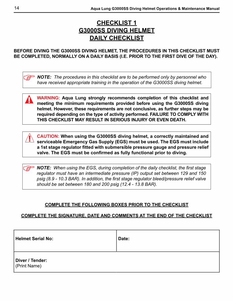
CHECKLIST 1G3000SS DIVING HELMET
DAILY CHECKLIST
BEFORE DIVING THE G3000SS DIVING HELMET, THE PROCEDURES IN THIS CHECKLIST MUST BE COMPLETED, NORMALLY ON A DAILY BASIS (I.E. PRIOR TO THE FIRST DIVE OF THE DAY).
NOTE: The procedures in this checklist are to be performed only by personnel who have received appropriate training in the operation of the G3000SS diving helmet.
NOTE: When using the EGS, during completion of the daily checklist, the first stage regulator must have an intermediate pressure (IP) output set between 129 and 150 psig (8.9 - 10.3 BAR). In addition, the first stage regulator bleed/pressure relief valve should be set between 180 and 200 psig (12.4 - 13.8 BAR).
WARNING: Aqua Lung strongly recommends completion of this checklist and meeting the minimum requirements provided before using the G3000SS diving helmet. However, these requirements are not conclusive, as further steps may be required depending on the type of activity performed. FAILURE TO COMPLY WITH THIS CHECKLIST MAY RESULT IN SERIOUS INJURY OR EVEN DEATH.
CAUTION: When using the G3000SS diving helmet, a correctly maintained and serviceable Emergency Gas Supply (EGS) must be used. The EGS must include a 1st stage regulator fitted with submersible pressure gauge and pressure relief valve. The EGS must be confirmed as fully functional prior to diving.
COMPLETE THE FOLLOWING BOXES PRIOR TO THE CHECKLIST
COMPLETE THE SIGNATURE, DATE AND COMMENTS AT THE END OF THE CHECKLIST
Helmet Serial No: Date:
Diver / Tender:(Print Name)

15
DAILY CHECKLIST (continued)ACTION PROCEDURE INITIALS
NECK RETAINER AND LOCKING SYSTEM(must be completed by diver/tender)
• Visually inspect the neck retainer assembly for signs of damage, such as bends. Confirm that the retainer fits properly.
• Make sure the locking system (both L and R) is properly working and not deformed in any way.
NECK DAM(must be completed by diver/tender)
• Visually inspect the neck dam ring for signs of damage, such as bends, scratches on the o-ring surface area or any other deformities.
• Visually inspect the neck seal for signs of damage such as tears, rips or cuts.
• If the quad ring is dry, lightly lubricate the quad ring.
• Replace the neck dam assembly onto the helmet and ensure a proper fit.
HELMET INSPECTION(must be completed by diver/tender)
• Visually inspect the helmet (interior and exterior) for damage and/or contamination.
NOTE: If a contaminated area of the shell is cleaned using a wire brush, the brush must be stainless steel or the area will be contaminated.
• Inspect the oral-nasal inhalation valve to ensure that it is installed correctly and that the oral-nasal mask is installed on the regulator.
• Check that the nose clearing device oper-ates without problems. If necessary lubricate o-rings and stem (Refer nose clearing device assembly section of the operations and main-tenance manual for guidance).
• Ensure the speakers and microphones are properly installed. Refer to the communications assembly section of the operations and maintenance manual for guidance.
• Ensure that the head liner fits properly and is secured to the inside of the helmet shell. Check for worn-off hook and loop, tears and/or rips. (Refer to the head liner assembly section of the operations and mainte-nance manual for guidance).
NOTE: The head liner should be fitted carefully into the helmet shell so that visible parts of the helmet shell (i.e. bare spots) are minimized.
16 Aqua Lung G3000SS Diving Helmet Operations & Maintenance Manual
DAILY CHECKLIST (continued)ACTION PROCEDURE INITIALS
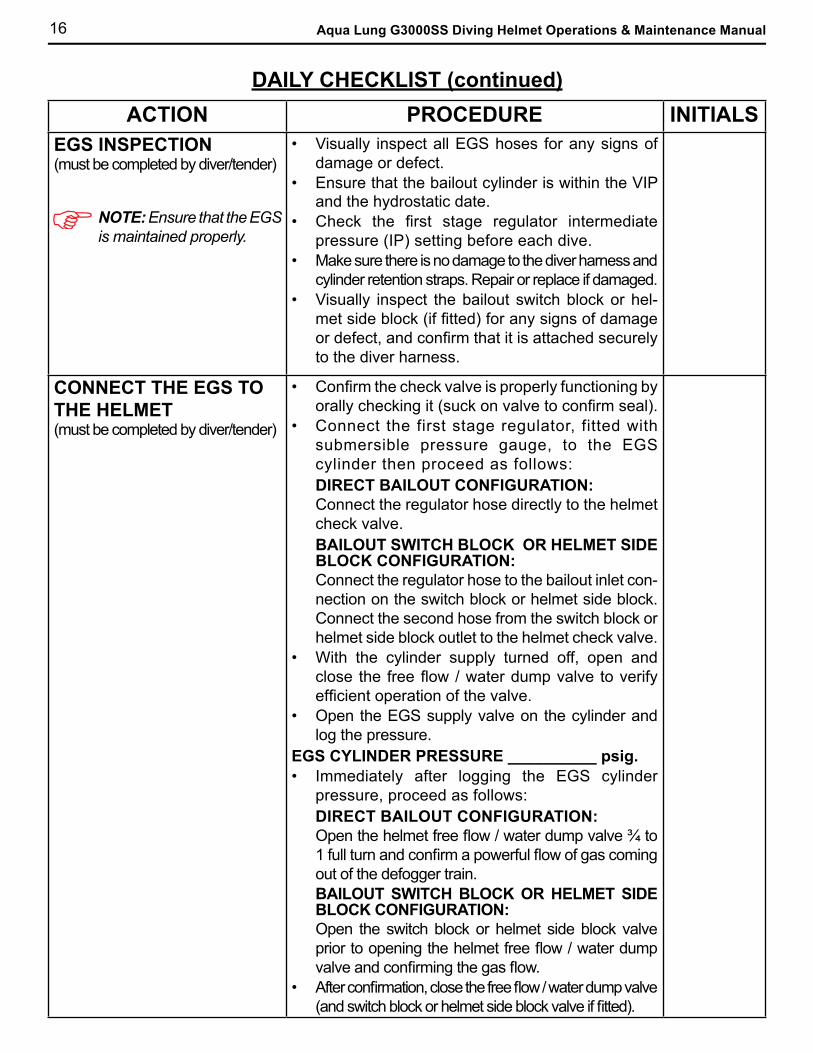
EGS INSPECTION(must be completed by diver/tender)
• Visually inspect all EGS hoses for any signs of damage or defect.
• Ensure that the bailout cylinder is within the VIP and the hydrostatic date.
• Check the first stage regulator intermediate pressure (IP) setting before each dive.
• Make sure there is no damage to the diver harness and cylinder retention straps. Repair or replace if damaged.
• Visually inspect the bailout switch block or hel-met side block (if fitted) for any signs of damage or defect, and confirm that it is attached securely to the diver harness.
CONNECT THE EGS TO THE HELMET(must be completed by diver/tender)
• Confirm the check valve is properly functioning by orally checking it (suck on valve to confirm seal).
• Connect the first stage regulator, fitted with submersible pressure gauge, to the EGS cylinder then proceed as follows: DIRECT BAILOUT CONFIGURATION: Connect the regulator hose directly to the helmet check valve. BAILOUT SWITCH BLOCK OR HELMET SIDE BLOCK CONFIGURATION:Connect the regulator hose to the bailout inlet con-nection on the switch block or helmet side block. Connect the second hose from the switch block or helmet side block outlet to the helmet check valve.
• With the cylinder supply turned off, open and close the free flow / water dump valve to verify efficient operation of the valve.
• Open the EGS supply valve on the cylinder and log the pressure.
EGS CYLINDER PRESSURE __________ psig.• Immediately after logging the EGS cylinder
pressure, proceed as follows:DIRECT BAILOUT CONFIGURATION: Open the helmet free flow / water dump valve ¾ to 1 full turn and confirm a powerful flow of gas coming out of the defogger train. BAILOUT SWITCH BLOCK OR HELMET SIDE BLOCK CONFIGURATION:Open the switch block or helmet side block valve prior to opening the helmet free flow / water dump valve and confirming the gas flow.
• After confirmation, close the free flow / water dump valve (and switch block or helmet side block valve if fitted).
NOTE: Ensure that the EGS is maintained properly.

17
DAILY CHECKLIST (continued)
ACTION PROCEDURE INITIALS
ATTACH THE UMBILICAL(to be completed by tender)
• Confirm the check valve is properly functioning by orally checking it (suck on valve to confirm seal).
• Blow air through the umbilical to remove any debris, and attach the umbilical into the umbilical adapter located on the check valve.
CHECK THE SECOND STAGE REGULATOR(must be completed by diver/tender)
• Slowly depress the purge button to full extent and confirm a sufficient audible flow of gas.
NOTE: If the regulator free flows, or if after fully depressing the purge button there is a weak flow of gas, the regulator needs to be adjusted or the low pressure valve should be replaced or serviced by a trained technician.
CONFIRM FUNCTION OF COMMUNICATIONS(to be completed by diver)
• Check all communications to confirm correct functioning.
CHECK DRY-SUIT INFLATION HOSE(must be completed by tender).
• If fitted, confirm the dry suit inflation valve and exhaust valve are functioning properly.
CHECK HELMET FOR LEAKS
• Apply soap and water to ALL gas fittings and connections (including the EGS) to check for leaks on the helmet.
FINAL CHECK(to be completed by tender)
• Check to ensure the neck retainer is in the correct position and properly locked.
• Ensure the diver's safety harness is in good condition.
• Check for free movement of the helmet.• Ensure the EGS hose quick disconnect is in good
condition and is functioning properly.• Ensure diver has boots, gloves, knife and other
accessories.
To Diver / Tender: Note comment on the space provided below. Be sure to log maintenance in the applicable maintenance log.
Comments:
Signature: Date:
18 Aqua Lung G3000SS Diving Helmet Operations & Maintenance Manual
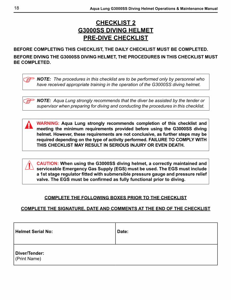
CHECKLIST 2G3000SS DIVING HELMET
PRE-DIVE CHECKLIST
BEFORE COMPLETING THIS CHECKLIST, THE DAILY CHECKLIST MUST BE COMPLETED.BEFORE DIVING THE G3000SS DIVING HELMET, THE PROCEDURES IN THIS CHECKLIST MUST BE COMPLETED.
NOTE: The procedures in this checklist are to be performed only by personnel who have received appropriate training in the operation of the G3000SS diving helmet.
NOTE: Aqua Lung strongly recommends that the diver be assisted by the tender or supervisor when preparing for diving and conducting the procedures in this checklist.
WARNING: Aqua Lung strongly recommends completion of this checklist and meeting the minimum requirements provided before using the G3000SS diving helmet. However, these requirements are not conclusive, as further steps may be required depending on the type of activity performed. FAILURE TO COMPLY WITH THIS CHECKLIST MAY RESULT IN SERIOUS INJURY OR EVEN DEATH.
CAUTION: When using the G3000SS diving helmet, a correctly maintained and serviceable Emergency Gas Supply (EGS) must be used. The EGS must include a 1st stage regulator fitted with submersible pressure gauge and pressure relief valve. The EGS must be confirmed as fully functional prior to diving.
COMPLETE THE FOLLOWING BOXES PRIOR TO THE CHECKLIST
COMPLETE THE SIGNATURE, DATE AND COMMENTS AT THE END OF THE CHECKLIST
Helmet Serial No: Date:
Diver/Tender:(Print Name)

19
PRE-DIVE CHECKLIST (continued)ACTION PROCEDURE INITIALS
SUPPLY GAS(must be completed by supervisor)
• Supervisor must ensure the diver has sufficient breathing gas pressure supplied to the helmet for depth.
BREATHING SYSTEM FUNCTION CHECK(must be completed by diver)
• Ensure proper functioning of free flow valve by opening and closing the valve.
• Check that breathing resistance is comfortable.• Ensure gas purge function by pressing in the
purge button.• Ensure the bail out cylinder valve is closed.
COMMUNICATION CHECK(must be completed by diver and communications operator)
• Ensure the speakers and microphone are functioning correctly.
CHECK DRY SUIT INFLATION HOSE(must be completed by tender)
• Ensure dry suit inflation valve and exhaust valve are functioning correctly.
FULL HELMET CHECK(must be checked by supervisor)
• Check all helmet gas fittings and connections for leaks. Check EGS for leaks.
• Check adjustment or fit of entire helmet, including the divers safety harness, free movement of the helmet, EGS hose quick disconnect, boots, gloves, knife and accessories.
EGS FUNCTIONAL CHECK(must be completed by diver and witnessed by tender)
• Turn off the main breathing gas supply and breathe down the umbilical (free flow / exhaust valve may be used to assist).
• Open EGS (bailout) supply (i.e. cylinder valve, or cylinder valve and switch block or helmet side block valve, depending on bailout configuration) and take two breaths from the EGS supply.
• Close the EGS supply valve(s) as follows:DIRECT BAILOUT CONFIGURATION: Close the cylinder valve (the hose remains pressurized). BAILOUT SWITCH BLOCK OR HELMET SIDE BLOCK CONFIGURATION:Close the switch block or helmet side block valve. The cylinder valve is to remain open. Both hoses remain pressurized.
• Open main breathing gas supply. Diver reports: Breathing OK.
NOTE: This check is mandatory and must be completed for all EGS (bailout) configurations. After checking, the EGS supply must be shut leaving the supply hose(s) pressurized.

20 Aqua Lung G3000SS Diving Helmet Operations & Maintenance Manual
PRE-DIVE CHECKLIST (continued)ACTION PROCEDURE INITIALS
CHECK DIVER'S ENTIRE RIG(must be completed by supervisor)
WARNING: Both latch catches must fit into place correctly or the helmet may flood.
• Check adjustment and fit of the entire rig, specific points:
• Head liner secured inside the helmet shell.
• Neck dam is installed.
• Neck retainer secured with both locking catches (L and R) engaged on neck retainer.
• Chin strap properly fastened.
• Check adjustment and fit of the diver's safety harness, free movement of the helmet, EGS hose quick disconnect, boots, gloves, etc.
• Ensure helmet supply pressure is at minimum 129 psig (8.9 bar) as per the regulated supply pressure table in Checklist 3, In-Water Checklist for Supervisor.
FINAL BREATHING CHECK(must be completed by diver)
• Check to ensure the helmet is breathing correctly with no complications.
NOTE: Ensure all equipment is properly adjusted and is properly functioning.
Comments:
Signature: Date:
21
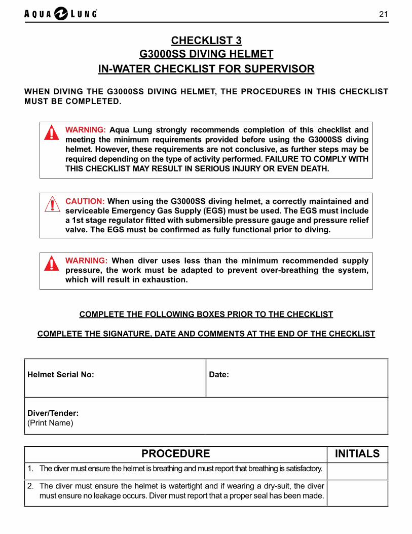
PROCEDURE INITIALS1. The diver must ensure the helmet is breathing and must report that breathing is satisfactory.
2. The diver must ensure the helmet is watertight and if wearing a dry-suit, the diver must ensure no leakage occurs. Diver must report that a proper seal has been made.
CHECKLIST 3G3000SS DIVING HELMET
IN-WATER CHECKLIST FOR SUPERVISOR
WHEN DIVING THE G3000SS DIVING HELMET, THE PROCEDURES IN THIS CHECKLIST MUST BE COMPLETED.
WARNING: Aqua Lung strongly recommends completion of this checklist and meeting the minimum requirements provided before using the G3000SS diving helmet. However, these requirements are not conclusive, as further steps may be required depending on the type of activity performed. FAILURE TO COMPLY WITH THIS CHECKLIST MAY RESULT IN SERIOUS INJURY OR EVEN DEATH.
CAUTION: When using the G3000SS diving helmet, a correctly maintained and serviceable Emergency Gas Supply (EGS) must be used. The EGS must include a 1st stage regulator fitted with submersible pressure gauge and pressure relief valve. The EGS must be confirmed as fully functional prior to diving.
WARNING: When diver uses less than the minimum recommended supply pressure, the work must be adapted to prevent over-breathing the system, which will result in exhaustion.
COMPLETE THE FOLLOWING BOXES PRIOR TO THE CHECKLIST
COMPLETE THE SIGNATURE, DATE AND COMMENTS AT THE END OF THE CHECKLIST
Helmet Serial No: Date:
Diver/Tender:(Print Name)
22 Aqua Lung G3000SS Diving Helmet Operations & Maintenance Manual
IN-WATER CHECKLIST (continued)
Comments:
Signature: Date:
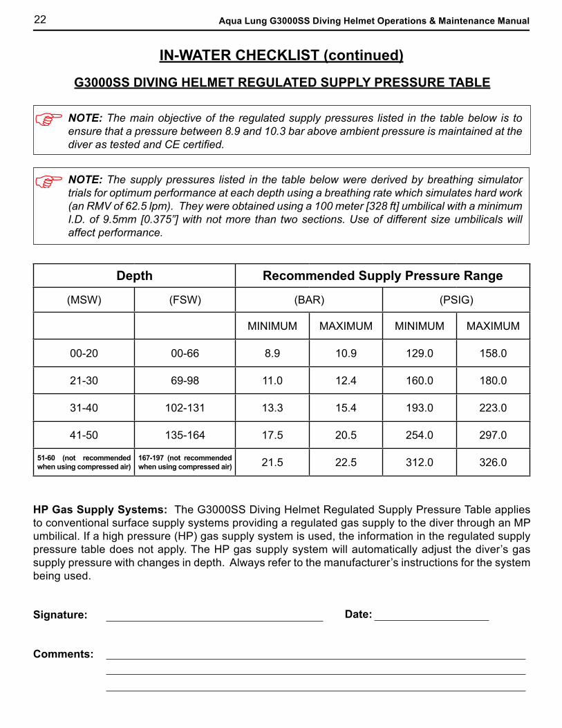
Depth Recommended Supply Pressure Range
(MSW) (FSW) (BAR) (PSIG)
MINIMUM MAXIMUM MINIMUM MAXIMUM
00-20 00-66 8.9 10.9 129.0 158.0
21-30 69-98 11.0 12.4 160.0 180.0
31-40 102-131 13.3 15.4 193.0 223.0
41-50 135-164 17.5 20.5 254.0 297.0
51-60 (not recommended when using compressed air)
167-197 (not recommended when using compressed air) 21.5 22.5 312.0 326.0
G3000SS DIVING HELMET REGULATED SUPPLY PRESSURE TABLE
HP Gas Supply Systems: The G3000SS Diving Helmet Regulated Supply Pressure Table applies to conventional surface supply systems providing a regulated gas supply to the diver through an MP umbilical. If a high pressure (HP) gas supply system is used, the information in the regulated supply pressure table does not apply. The HP gas supply system will automatically adjust the diver’s gas supply pressure with changes in depth. Always refer to the manufacturer’s instructions for the system being used.
NOTE: The main objective of the regulated supply pressures listed in the table below is to ensure that a pressure between 8.9 and 10.3 bar above ambient pressure is maintained at the diver as tested and CE certified.
NOTE: The supply pressures listed in the table below were derived by breathing simulator trials for optimum performance at each depth using a breathing rate which simulates hard work (an RMV of 62.5 lpm). They were obtained using a 100 meter [328 ft] umbilical with a minimum I.D. of 9.5mm [0.375”] with not more than two sections. Use of different size umbilicals will affect performance.
23
CHECKLIST 4G3000SS DIVING HELMET
POST-DIVE CHECKLIST
THE POST-DIVE CHECKLIST MUST BE COMPLETED AT LEAST ONCE A DAY WHEN DIVING USING THE G3000SS DIVING HELMET.
NOTE: The procedures in this checklist are to be performed only by personnel who have received appropriate training in the operation of the G3000SS diving helmet.
WARNING: Aqua Lung strongly recommends completion of this checklist and meeting the minimum requirements provided before using the G3000SS diving helmet. However, these requirements are not conclusive, as further steps may be required depending on the type of activity performed. FAILURE TO COMPLY WITH THIS CHECKLIST MAY RESULT IN SERIOUS INJURY OR EVEN DEATH.
COMPLETE THE FOLLOWING BOXES PRIOR TO THE CHECKLIST
COMPLETE THE SIGNATURE, DATE AND COMMENTS AT THE END OF THE CHECKLIST
Helmet Serial No: Date:
Diver/Tender:(Print Name)

24 Aqua Lung G3000SS Diving Helmet Operations & Maintenance Manual
POST-DIVE CHECKLIST (continued)
PROCEDURE INITIALS
1. Secure and bleed down the breathing gas supply and the EGS hose.
2. Disconnect all helmet gas connections and disconnect the communication wires / cable. Replace hose caps onto hose adapters after removing all water from the hose adapter.
3. Wash the outside of the helmet and all external fittings completely with fresh water. This removes dirt and prevents surface corrosion. If required, wash with soap and water, rinse with fresh water and allow to dry.
4. Visually inspect the helmet fully for damage.
5. Remove the speakers from the headliner.
6. Remove the head liner. Visually inspect for damage and/or deterioration. If the head liner is wet, air dry it.
NOTE: The head liner may be washed as required.
7. If required, and particularly if the inside of the regulator was exposed to salt or contaminated water, remove the regulator and the oral-nasal mask from the helmet. Wash the exhaust assembly carefully with soap and water, rinse thoroughly with fresh water and allow to dry. DO NOT allow water to enter the regulator body. Re-install into helmet upon completion.
After diving in extreme conditions (e.g. sand, sediment), or if wet breathing was experienced, proceed as follows (the regulator may remain installed in the helmet):
• Remove exhaust valve cover and the complete diaphragm assembly from the regulator.
• Rinse the diaphragm assembly and the exposed inside of the regulator with fresh water.
• Check the condition and correct installation of both diaphragms.• Dry out and reinstall the diaphragm assembly and the exhalation valve cover.
NOTE: Refer to the separate Apeks Technical Manual: GX300 REGULATOR FOR THE AQUA LUNG G3000SS DIVING HELMET - MAINTENANCE MANUAL for guidance on installation and removal of the regulator.
25
POST-DIVE CHECKLIST (continued)
PROCEDURE INITIALS
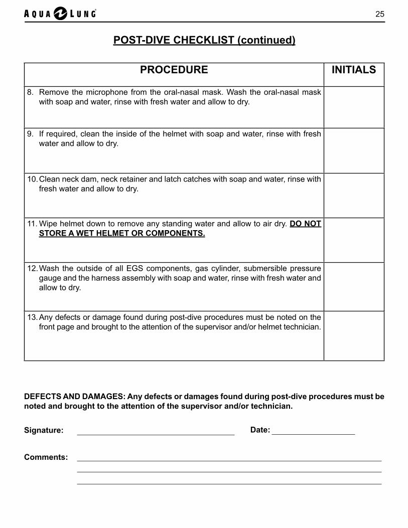
8. Remove the microphone from the oral-nasal mask. Wash the oral-nasal mask with soap and water, rinse with fresh water and allow to dry.
9. If required, clean the inside of the helmet with soap and water, rinse with fresh water and allow to dry.
10. Clean neck dam, neck retainer and latch catches with soap and water, rinse with fresh water and allow to dry.
11. Wipe helmet down to remove any standing water and allow to air dry. DO NOT STORE A WET HELMET OR COMPONENTS.
12. Wash the outside of all EGS components, gas cylinder, submersible pressure gauge and the harness assembly with soap and water, rinse with fresh water and allow to dry.
13. Any defects or damage found during post-dive procedures must be noted on the front page and brought to the attention of the supervisor and/or helmet technician.
Comments:
DEFECTS AND DAMAGES: Any defects or damages found during post-dive procedures must be noted and brought to the attention of the supervisor and/or technician.
Signature: Date:
26 Aqua Lung G3000SS Diving Helmet Operations & Maintenance Manual
V. HELMET TECHNICAL INFORMATION
AUTHORIZED TECHNICIANS
The technical procedures in this manual are to be performed only by personnel who have received factory authorized training through an Aqua Lung Service & Repair Seminar.
TECHNICAL SECTION
FACTORY PRESCRIBED PROCEDURES
This manual provides factory prescribed procedures for the correct service and repair of the G3000SS diving helmet. It is strongly recommended that all repairs are completed in accordance with this manual.
If you do not completely understand all of the procedures outlined in this manual, contact Aqua Lung to speak directly with a technical advisor before proceeding any further.
SCHEDULED SERVICE
1. The G3000SS Diving Helmet is subject to annual service regardless of usage.
2. The Annual Inspection and Maintenance Checklist must be followed for annual service. See Checklist 6 for details of annual service.
3. The annual service kit (P/N 400180) contains all parts that are replaced annually (See Appendix R)for details of this kit.
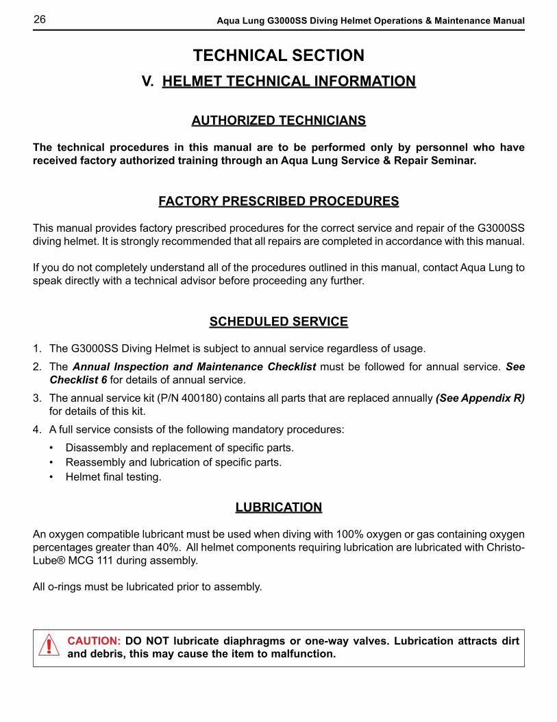
4. A full service consists of the following mandatory procedures:
• Disassembly and replacement of specific parts.• Reassembly and lubrication of specific parts.• Helmet final testing.
LUBRICATION
An oxygen compatible lubricant must be used when diving with 100% oxygen or gas containing oxygen percentages greater than 40%. All helmet components requiring lubrication are lubricated with Christo-Lube® MCG 111 during assembly.
All o-rings must be lubricated prior to assembly.
CAUTION: DO NOT lubricate diaphragms or one-way valves. Lubrication attracts dirt and debris, this may cause the item to malfunction.
27
TECHNICIAN CHECKLIST
The following technician checklists are provided to assist all technicians:
• Monthly Inspection & Maintenance Checklist ………………………………………………..Section VII
• Annual Inspection & Maintenance Checklist …………………………………………………Section VII
GENERAL GUIDELINES
1. In order to correctly perform the procedures outlined in this manual, it is important to follow each step exactly in the order given. Read over the entire manual to become familiar with all procedures before attempting to service or repair the G3000SS diving helmet.
2. Keep the manual open beside you for reference while performing each procedure. Do not rely on memory.
3. All service and repair should be carried out in a work area specifically set up and equipped for the task. Adequate lighting, cleanliness, and easy access to all required tools are essential for an efficient repair facility.
4. As each unit is disassembled, reusable components should be segregated and not allowed to intermix with non-reusable parts. Delicate parts, including inlet fittings and crowns which contain critical sealing surfaces, must be protected and isolated form other parts to prevent damage during the cleaning procedure.
5. Use only genuine Aqua Lung parts provided in the service kits. DO NOT attempt to substitute any part with another manufacturer's, regardless of any similarity in shape or size. Substitution with other manufacturer's parts constitutes an after-market modification of the product and renders all warranties null and void.
6. Do not attempt to reuse mandatory replacement parts under any circumstance, regardless of the amount of use the product has received since it was manufactured or last serviced.
7. When reassembling, it is important to follow every torque specification prescribed in this manual, using a calibrated Newton Meter (Nm) or Inch Pound (in lb) torque wrench. Some parts are made of either brass or composite materials and can be permanently damaged by undue stress.
28 Aqua Lung G3000SS Diving Helmet Operations & Maintenance Manual
VI. STEP-BY-STEP DISASSEMBLY / REASSEMBLY PROCEDURES
The technical procedures in this section are to be performed only by personnel who have received factory authorized training through an Aqua Lung Service and Repair Seminar.
NOTES ON DISASSEMBLY AND REASSEMBLY
1. All components must be clean and fully serviceable prior to assembly.
2. All o-rings must be lubricated prior to assembly.
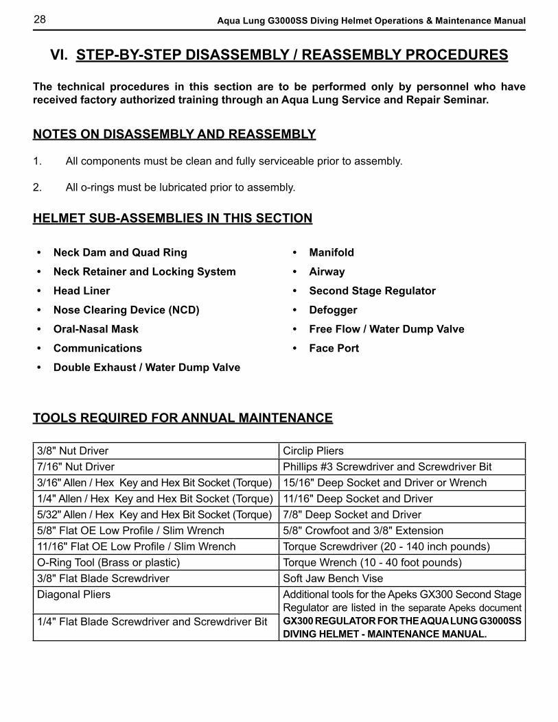
TOOLS REQUIRED FOR ANNUAL MAINTENANCE
• Neck Dam and Quad Ring
• Neck Retainer and Locking System
• Head Liner
• Nose Clearing Device (NCD)
• Oral-Nasal Mask
• Communications
• Double Exhaust / Water Dump Valve
HELMET SUB-ASSEMBLIES IN THIS SECTION
• Manifold
• Airway
• Second Stage Regulator
• Defogger
• Free Flow / Water Dump Valve
• Face Port
3/8" Nut Driver Circlip Pliers7/16" Nut Driver Phillips #3 Screwdriver and Screwdriver Bit3/16" Allen / Hex Key and Hex Bit Socket (Torque) 15/16" Deep Socket and Driver or Wrench1/4" Allen / Hex Key and Hex Bit Socket (Torque) 11/16" Deep Socket and Driver5/32" Allen / Hex Key and Hex Bit Socket (Torque) 7/8" Deep Socket and Driver5/8" Flat OE Low Profile / Slim Wrench 5/8" Crowfoot and 3/8" Extension11/16" Flat OE Low Profile / Slim Wrench Torque Screwdriver (20 - 140 inch pounds)O-Ring Tool (Brass or plastic) Torque Wrench (10 - 40 foot pounds)3/8" Flat Blade Screwdriver Soft Jaw Bench ViseDiagonal Pliers Additional tools for the Apeks GX300 Second Stage
Regulator are listed in the separate Apeks document GX300 REGULATOR FOR THE AQUA LUNG G3000SS DIVING HELMET - MAINTENANCE MANUAL.
1/4" Flat Blade Screwdriver and Screwdriver Bit
29
G3000SS DIVING HELMET DISASSEMBLY PROCEDURES
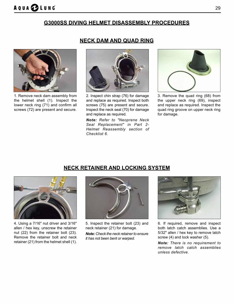
1. Remove neck dam assembly from the helmet shell (1). Inspect the lower neck ring (71) and confirm all screws (72) are present and secure.
NECK DAM AND QUAD RING
3. Remove the quad ring (68) from the upper neck ring (69), inspect and replace as required. Inspect the quad ring groove on upper neck ring for damage.
5. Inspect the retainer bolt (23) and neck retainer (21) for damage.Note: Check the neck retainer to ensure it has not been bent or warped.
6. If required, remove and inspect both latch catch assemblies. Use a 5/32" allen / hex key to remove latch screw (4) and lock washer (5). Note: There is no requirement to remove latch catch assemblies unless defective.
NECK RETAINER AND LOCKING SYSTEM
4. Using a 7/16" nut driver and 3/16" allen / hex key, unscrew the retainer nut (22) from the retainer bolt (23). Remove the retainer bolt and neck retainer (21) from the helmet shell (1).
2. Inspect chin strap (76) for damage and replace as required. Inspect both screws (75) are present and secure. Inspect the neck seal (70) for damage and replace as required.Note: Refer to "Neoprene Neck Seal Replacement" in Part 2- Helmet Reassembly section of Checklist 6.
30 Aqua Lung G3000SS Diving Helmet Operations & Maintenance Manual
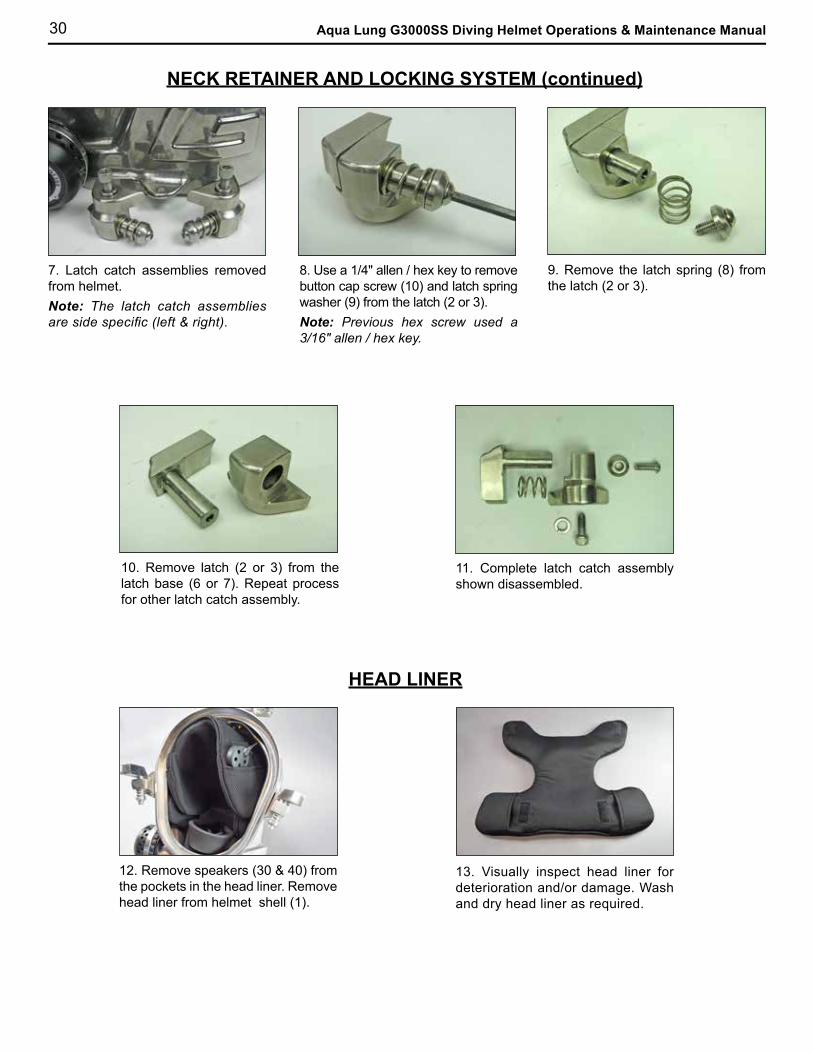
10. Remove latch (2 or 3) from the latch base (6 or 7). Repeat process for other latch catch assembly.
11. Complete latch catch assembly shown disassembled.
12. Remove speakers (30 & 40) from the pockets in the head liner. Remove head liner from helmet shell (1).
13. Visually inspect head liner for deterioration and/or damage. Wash and dry head liner as required.
HEAD LINER
NECK RETAINER AND LOCKING SYSTEM (continued)
9. Remove the latch spring (8) from the latch (2 or 3).
7. Latch catch assemblies removed from helmet.Note: The latch catch assemblies are side specific (left & right).
8. Use a 1/4" allen / hex key to remove button cap screw (10) and latch spring washer (9) from the latch (2 or 3).Note: Previous hex screw used a 3/16" allen / hex key.
31
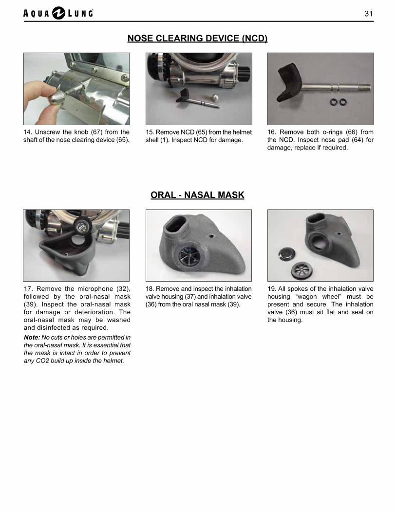
14. Unscrew the knob (67) from the shaft of the nose clearing device (65).
15. Remove NCD (65) from the helmet shell (1). Inspect NCD for damage.
16. Remove both o-rings (66) from the NCD. Inspect nose pad (64) for damage, replace if required.
18. Remove and inspect the inhalation valve housing (37) and inhalation valve (36) from the oral nasal mask (39).
19. All spokes of the inhalation valve housing “wagon wheel” must be present and secure. The inhalation valve (36) must sit flat and seal on the housing.
17. Remove the microphone (32), followed by the oral-nasal mask (39). Inspect the oral-nasal mask for damage or deterioration. The oral-nasal mask may be washed and disinfected as required.Note: No cuts or holes are permitted in the oral-nasal mask. It is essential that the mask is intact in order to prevent any CO2 build up inside the helmet.
NOSE CLEARING DEVICE (NCD)
ORAL - NASAL MASK
32 Aqua Lung G3000SS Diving Helmet Operations & Maintenance Manual
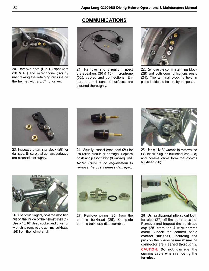
20. Remove both (L & R) speakers (30 & 40) and microphone (32) by unscrewing the retaining nuts inside the helmet with a 3/8” nut driver.
21. Remove and visually inspect the speakers (30 & 40), microphone (32), cables and connections. En-sure that all contact surfaces are cleaned thoroughly.
22. Remove the comms terminal block (29) and both communications posts (24). The terminal block is held in place inside the helmet by the posts.
23. Inspect the terminal block (29) for damage. Ensure that contact surfaces are cleaned thoroughly.
24. Visually inspect each post (24) for insulation cracks or damage. Replace posts and plastic tubing (85) as required.Note: There is no requirement to remove the posts unless damaged.
26. Use your fingers, hold the modified nut on the inside of the helmet shell (1). Use a 15/16" deep socket and driver or wrench to remove the comms bulkhead (26) from the helmet shell.
27. Remove o-ring (25) from the comms bulkhead (26). Complete comms bulkhead disassembled.
25. Use a 11/16" wrench to remove the SS blank plug or bulkhead cap (28) and comms cable from the comms bulkhead (26).
COMMUNICATIONS
28. Using diagonal pliers, cut both ferrules (27) off the comms cable. Remove and inspect the bulkhead cap (28) from the 4 wire comms cable. Check the comms cable contact surfaces, including the pins on the hi-use or marsh marine connector are cleaned thoroughly.CAUTION: Do not damage the comms cable when removing the ferrules.
33
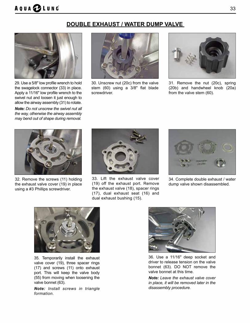
30. Unscrew nut (20c) from the valve stem (60) using a 3/8" flat blade screwdriver.
31. Remove the nut (20c), spring (20b) and handwheel knob (20a) from the valve stem (60).
32. Remove the screws (11) holding the exhaust valve cover (19) in place using a #3 Phillips screwdriver.
34. Complete double exhaust / water dump valve shown disassembled.
35. Temporarily install the exhaust valve cover (19), three spacer rings (17) and screws (11) onto exhaust port. This will keep the valve body (55) from moving when loosening the valve bonnet (63).Note: Install screws in triangle formation.
36. Use a 11/16" deep socket and driver to release tension on the valve bonnet (63). DO NOT remove the valve bonnet at this time.Note: Leave the exhaust valve cover in place, it will be removed later in the disassembly procedure.
33. Lift the exhaust valve cover (19) off the exhaust port. Remove the exhaust valve (18), spacer rings (17), dual exhaust seat (16) and dual exhaust bushing (15).
29. Use a 5/8" low profile wrench to hold the swagelock connector (33) in place. Apply a 11/16" low profile wrench to the swivel nut and loosen it just enough to allow the airway assembly (31) to rotate.Note: Do not unscrew the swivel nut all the way, otherwise the airway assembly may bend out of shape during removal.
DOUBLE EXHAUST / WATER DUMP VALVE
34 Aqua Lung G3000SS Diving Helmet Operations & Maintenance Manual
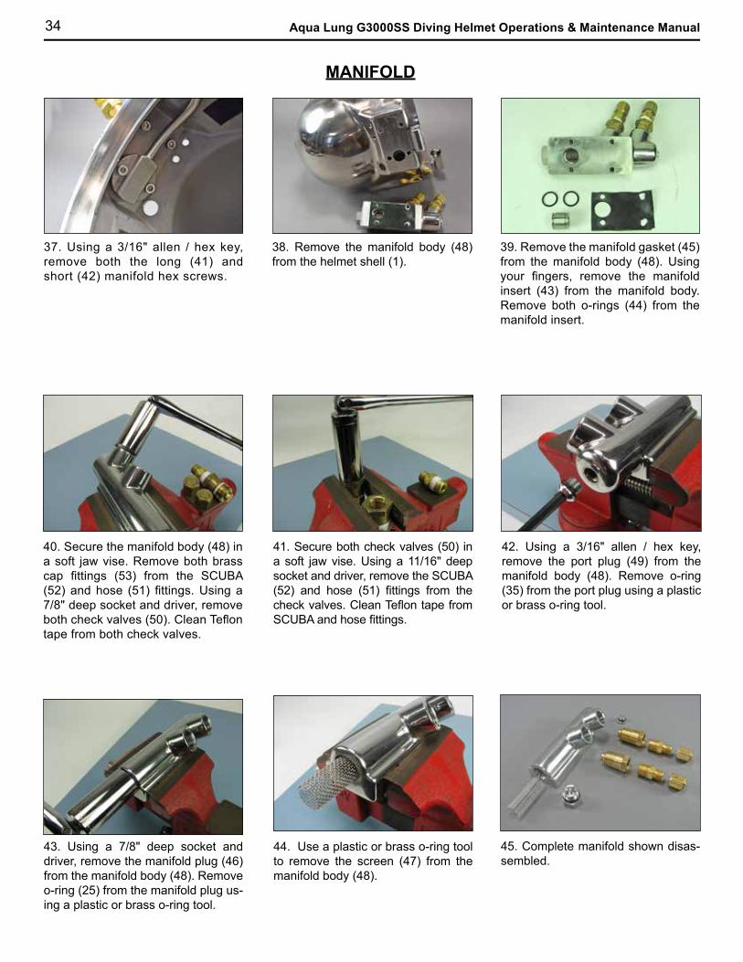
37. Using a 3/16" allen / hex key, remove both the long (41) and short (42) manifold hex screws.
38. Remove the manifold body (48) from the helmet shell (1).
39. Remove the manifold gasket (45) from the manifold body (48). Using your fingers, remove the manifold insert (43) from the manifold body. Remove both o-rings (44) from the manifold insert.
40. Secure the manifold body (48) in a soft jaw vise. Remove both brass cap fittings (53) from the SCUBA (52) and hose (51) fittings. Using a 7/8" deep socket and driver, remove both check valves (50). Clean Teflon tape from both check valves.
41. Secure both check valves (50) in a soft jaw vise. Using a 11/16" deep socket and driver, remove the SCUBA (52) and hose (51) fittings from the check valves. Clean Teflon tape from SCUBA and hose fittings.
42. Using a 3/16" allen / hex key, remove the port plug (49) from the manifold body (48). Remove o-ring (35) from the port plug using a plastic or brass o-ring tool.
43. Using a 7/8" deep socket and driver, remove the manifold plug (46) from the manifold body (48). Remove o-ring (25) from the manifold plug us-ing a plastic or brass o-ring tool.
44. Use a plastic or brass o-ring tool to remove the screen (47) from the manifold body (48).
45. Complete manifold shown disas-sembled.
MANIFOLD
35
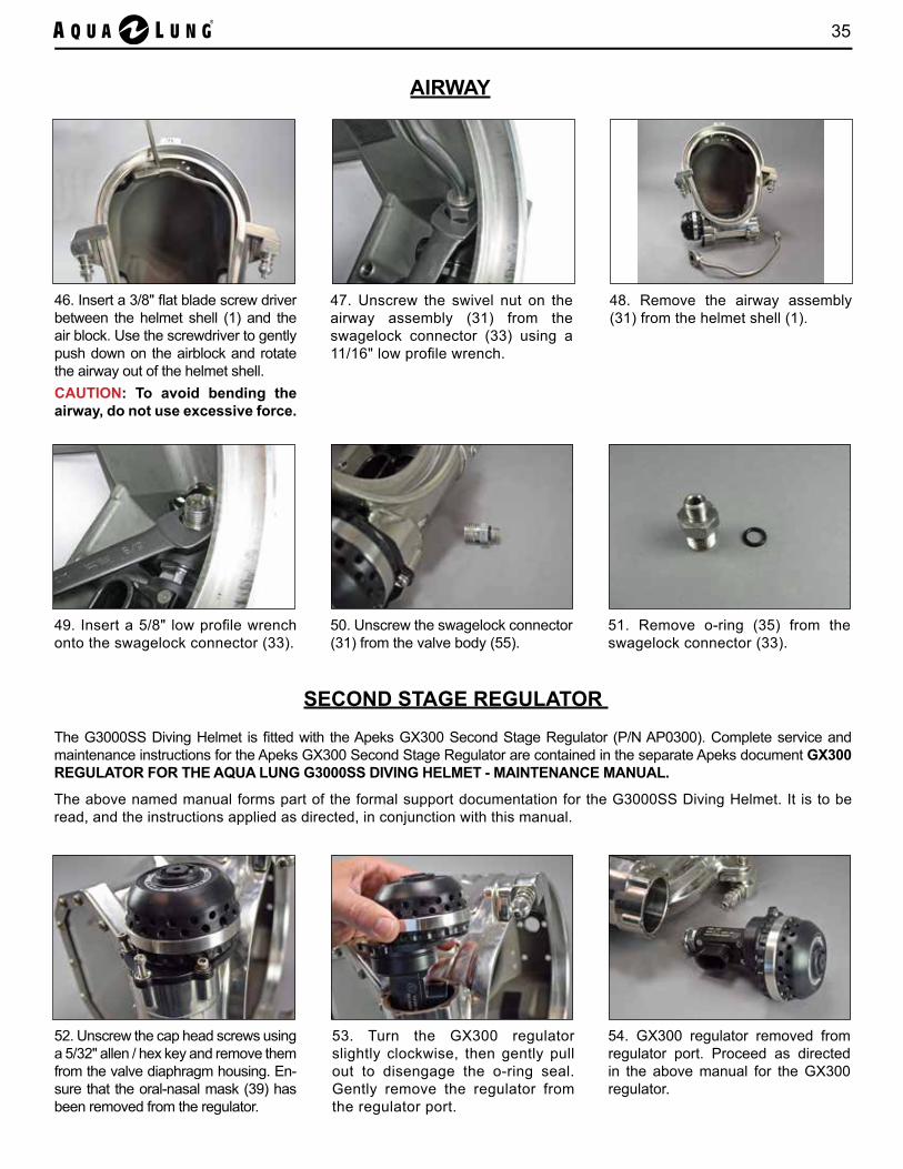
47. Unscrew the swivel nut on the airway assembly (31) from the swagelock connector (33) using a 11/16" low profile wrench.
48. Remove the airway assembly (31) from the helmet shell (1).
49. Insert a 5/8" low profile wrench onto the swagelock connector (33).
50. Unscrew the swagelock connector (31) from the valve body (55).
51. Remove o-ring (35) from the swagelock connector (33).
AIRWAY
46. Insert a 3/8" flat blade screw driver between the helmet shell (1) and the air block. Use the screwdriver to gently push down on the airblock and rotate the airway out of the helmet shell.CAUTION: To avoid bending the airway, do not use excessive force.
SECOND STAGE REGULATOR
The G3000SS Diving Helmet is fitted with the Apeks GX300 Second Stage Regulator (P/N AP0300). Complete service and maintenance instructions for the Apeks GX300 Second Stage Regulator are contained in the separate Apeks document GX300 REGULATOR FOR THE AQUA LUNG G3000SS DIVING HELMET - MAINTENANCE MANUAL.
The above named manual forms part of the formal support documentation for the G3000SS Diving Helmet. It is to be read, and the instructions applied as directed, in conjunction with this manual.
52. Unscrew the cap head screws using a 5/32" allen / hex key and remove them from the valve diaphragm housing. En-sure that the oral-nasal mask (39) has been removed from the regulator.
54. GX300 regulator removed from regulator port. Proceed as directed in the above manual for the GX300 regulator.
53. Turn the GX300 regulator slightly clockwise, then gently pull out to disengage the o-ring seal. Gently remove the regulator from the regulator port.

36 Aqua Lung G3000SS Diving Helmet Operations & Maintenance Manual
55. Remove the defogger train (38) from the free flow barrel (34).Note: Do not use excessive force, the defogger train should slide out easily.
56. Remove the free flow barrel (34) from the free flow / water dump valve.Note: Do not use excessive force, the free flow barrel should slide out easily.
57. The helmet defogger system consists of two components, the defogger train (38) and the free flow barrel (34).
60. Unscrew the valve bonnet (63) from the valve body (55).
61. Remove the valve stem (60) from the valve bonnet (63).
62. Remove the o-ring (62) and Teflon washer (61) from the valve stem (60).Note: If the o-ring and Teflon washer are not on the valve stem, check inside the valve bonnet.
63. Insert a brass or plastic o-ring tool into the valve body (55) and remove both copper washers (59).
DEFOGGER
FREE FLOW / WATER DUMP VALVE
58. Using a #3 Phillips screwdriver, remove the screws (11), spacer rings (17) and exhaust valve cover (19) from the exhaust port.
59. Remove the free flow / water dump valve assembly from exhaust port.
37
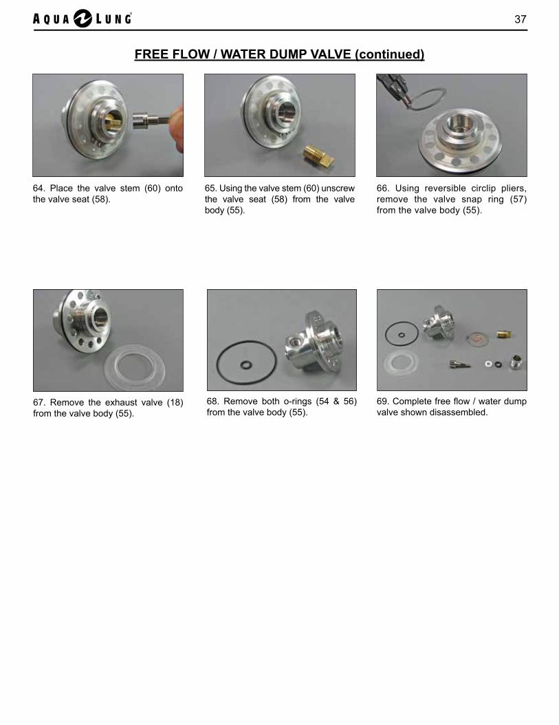
64. Place the valve stem (60) onto the valve seat (58).
65. Using the valve stem (60) unscrew the valve seat (58) from the valve body (55).
66. Using reversible circlip pliers, remove the valve snap ring (57) from the valve body (55).
67. Remove the exhaust valve (18) from the valve body (55).
68. Remove both o-rings (54 & 56) from the valve body (55).
69. Complete free flow / water dump valve shown disassembled.
FREE FLOW / WATER DUMP VALVE (continued)

38 Aqua Lung G3000SS Diving Helmet Operations & Maintenance Manual
70. Using a #3 Phillips screwdriver, remove the screws (11) from the retainer port (12).
71. Remove the retainer port (12) from the face port (13).
72. Separate the face port (13) from the helmet shell (1).
73. Use a brass or plastic o-ring tool to remove o-ring (14) from the groove in the face port on the helmet shell (1).
74. Complete face port shown disassembled.
FACE PORT
NOTE: Before beginning reassembly, perform parts cleaning and lubrication in accordance with Appendix Q: Cleaning and Lubricating
DISASSEMBLY OF THE G3000SS DIVING HELMET IS NOW COMPLETE

39
G3000SS DIVING HELMET REASSEMBLY PROCEDURES
2. Place the face port (13) into the helmet shell (1). Note: If needed, clean the face port with soapy water prior to installation.
1. Use a clean cloth to wipe any particles or debris off the o-ring (14). Install o-ring into the groove on the helmet shell (1). Note: Lubricate the face port o-ring sparingly, i.e. a small amount of Christo-Lube® MCG 111 only.
FACE PORT
3. Place the port retainer (12) over the face port (13) with the beveled edge on the bottom, facing the helmet.
4. Insert the screws (11) through the port retainer (12) and into the helmet shell (1). Hand tighten the screws with a #3 Phillips screwdriver.Note: If any resistance is felt, stop and start over to ensure cross threading is not occurring.
5. Using a #3 Phillips screwdriver bit and inch pound torque wrench, torque each screw (11) to a value of 45 in lb (5 Nm).
40 Aqua Lung G3000SS Diving Helmet Operations & Maintenance Manual
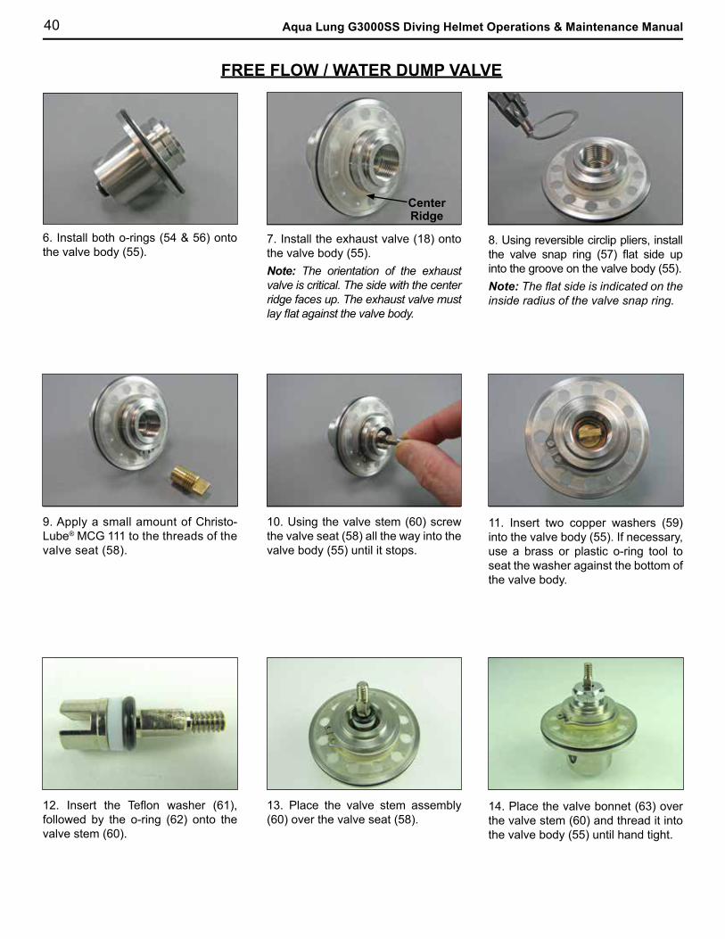
10. Using the valve stem (60) screw the valve seat (58) all the way into the valve body (55) until it stops.
9. Apply a small amount of Christo-Lube® MCG 111 to the threads of the valve seat (58).
8. Using reversible circlip pliers, install the valve snap ring (57) flat side up into the groove on the valve body (55).Note: The flat side is indicated on the inside radius of the valve snap ring.
7. Install the exhaust valve (18) onto the valve body (55). Note: The orientation of the exhaust valve is critical. The side with the center ridge faces up. The exhaust valve must lay flat against the valve body.
6. Install both o-rings (54 & 56) onto the valve body (55).
11. Insert two copper washers (59) into the valve body (55). If necessary, use a brass or plastic o-ring tool to seat the washer against the bottom of the valve body.
13. Place the valve stem assembly (60) over the valve seat (58).
12. Insert the Teflon washer (61), followed by the o-ring (62) onto the valve stem (60).
14. Place the valve bonnet (63) over the valve stem (60) and thread it into the valve body (55) until hand tight.
FREE FLOW / WATER DUMP VALVE
CenterRidge

41
15. Install the free flow / water dump valve into the helmet shell (1). Align the swagelock connector opening with the notch on the inside of the helmet. Note: The swagelock connector opening must be aligned with the notch in order to install the airway assembly.
16. Temporarily install the exhaust valve cover (19), three spacer rings (17) and three screws (11) onto ex-haust port. This will keep the valve body (55) from moving when torquing the valve bonnet (63).Note: Install screws in triangle formation.
FREE FLOW / WATER DUMP VALVE (continued)
Notch
20. Secure the manifold body (48) in a soft jaw vise. Insert the screen (47) into the manifold body, making sure it is aligned with the end of the threads.
MANIFOLD
22. Install o-ring (35) onto the port plug (49). Install the port plug into the manifold body (48) hand tight. Using a 3/16" hex / allen key bit and inch pound torque wrench, torque the port plug to a value of 45 in lb (5 Nm).
17. Place o-ring (35) onto the swa-gelock connector (33). Screw the swagelock connector into the opening on the valve body (55) until hand tight. Using a 5/8" crowfoot, 3/8" extension and inch pound torque wrench, torque the swagelock connector to a value of 45 in lb (5 Nm).
19. Press inward on the air block to insert the airway assembly (31) into the helmet shell (1).CAUTION: Do not pinch your fingers or hand in between the airway assembly and the helmet shell during installation.
AIRWAY
18. Screw the swivel nut all the way down onto the swagelock connector (33) until hand tight. Make sure the airway assembly can rotate slightly.Note: Make sure the swivel nut is threaded all the way down onto the swagelock connector before pressing the airway assembly into the helmet
21. Install o-ring (25) onto the manifold plug (46). Screw the manifold plug into the manifold body (48) hand tight. Us-ing a 7/8" deep socket and inch pound torque wrench, torque the manifold plug to a value of 90 in lb (10 Nm).
42 Aqua Lung G3000SS Diving Helmet Operations & Maintenance Manual
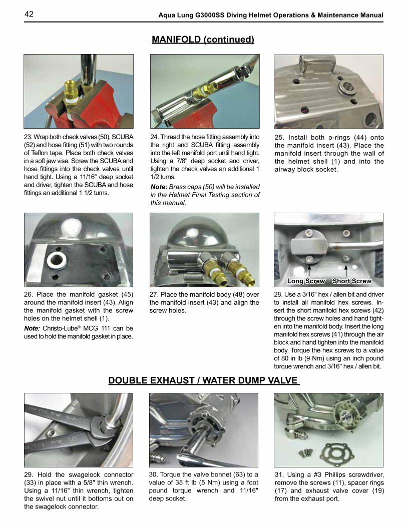
26. Place the manifold gasket (45) around the manifold insert (43). Align the manifold gasket with the screw holes on the helmet shell (1).Note: Christo-Lube® MCG 111 can be used to hold the manifold gasket in place.
27. Place the manifold body (48) over the manifold insert (43) and align the screw holes.
23. Wrap both check valves (50), SCUBA (52) and hose fitting (51) with two rounds of Teflon tape. Place both check valves in a soft jaw vise. Screw the SCUBA and hose fittings into the check valves until hand tight. Using a 11/16" deep socket and driver, tighten the SCUBA and hose fittings an additional 1 1/2 turns.
24. Thread the hose fitting assembly into the right and SCUBA fitting assembly into the left manifold port until hand tight. Using a 7/8" deep socket and driver, tighten the check valves an additional 1 1/2 turns. Note: Brass caps (50) will be installed in the Helmet Final Testing section of this manual.
25. Install both o-rings (44) onto the manifold insert (43). Place the manifold insert through the wall of the helmet shell (1) and into the airway block socket.
Long Screw Short Screw
28. Use a 3/16" hex / allen bit and driver to install all manifold hex screws. In-sert the short manifold hex screws (42) through the screw holes and hand tight-en into the manifold body. Insert the long manifold hex screws (41) through the air block and hand tighten into the manifold body. Torque the hex screws to a value of 80 in lb (9 Nm) using an inch pound torque wrench and 3/16" hex / allen bit.
DOUBLE EXHAUST / WATER DUMP VALVE
31. Using a #3 Phillips screwdriver, remove the screws (11), spacer rings (17) and exhaust valve cover (19) from the exhaust port.
30. Torque the valve bonnet (63) to a value of 35 ft lb (5 Nm) using a foot pound torque wrench and 11/16" deep socket.
MANIFOLD (continued)
29. Hold the swagelock connector (33) in place with a 5/8" thin wrench. Using a 11/16" thin wrench, tighten the swivel nut until it bottoms out on the swagelock connector.
43
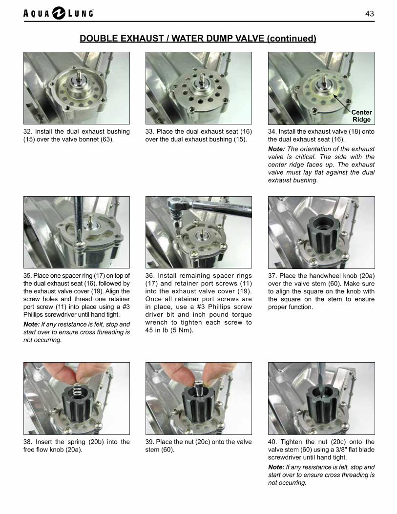
32. Install the dual exhaust bushing (15) over the valve bonnet (63).
33. Place the dual exhaust seat (16) over the dual exhaust bushing (15).
34. Install the exhaust valve (18) onto the dual exhaust seat (16). Note: The orientation of the exhaust valve is critical. The side with the center ridge faces up. The exhaust valve must lay flat against the dual exhaust bushing.
35. Place one spacer ring (17) on top of the dual exhaust seat (16), followed by the exhaust valve cover (19). Align the screw holes and thread one retainer port screw (11) into place using a #3 Phillips screwdriver until hand tight.Note: If any resistance is felt, stop and start over to ensure cross threading is not occurring.
37. Place the handwheel knob (20a) over the valve stem (60). Make sure to align the square on the knob with the square on the stem to ensure proper function.
36. Install remaining spacer rings (17) and retainer port screws (11) into the exhaust valve cover (19). Once all retainer port screws are in place, use a #3 Phillips screw driver bit and inch pound torque wrench to tighten each screw to 45 in lb (5 Nm).
38. Insert the spring (20b) into the free flow knob (20a).
39. Place the nut (20c) onto the valve stem (60).
DOUBLE EXHAUST / WATER DUMP VALVE (continued)
40. Tighten the nut (20c) onto the valve stem (60) using a 3/8" flat blade screwdriver until hand tight.Note: If any resistance is felt, stop and start over to ensure cross threading is not occurring.
CenterRidge
44 Aqua Lung G3000SS Diving Helmet Operations & Maintenance Manual
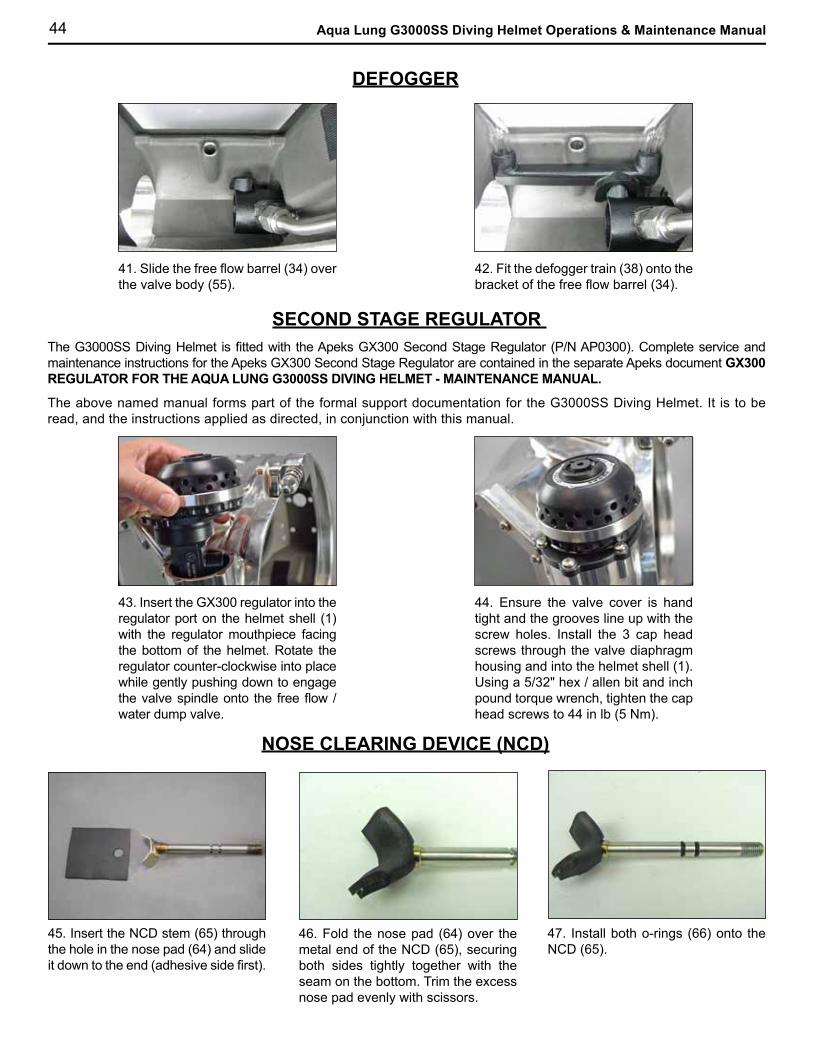
42. Fit the defogger train (38) onto the bracket of the free flow barrel (34).
41. Slide the free flow barrel (34) over the valve body (55).
DEFOGGER
44. Ensure the valve cover is hand tight and the grooves line up with the screw holes. Install the 3 cap head screws through the valve diaphragm housing and into the helmet shell (1). Using a 5/32" hex / allen bit and inch pound torque wrench, tighten the cap head screws to 44 in lb (5 Nm).
43. Insert the GX300 regulator into the regulator port on the helmet shell (1) with the regulator mouthpiece facing the bottom of the helmet. Rotate the regulator counter-clockwise into place while gently pushing down to engage the valve spindle onto the free flow / water dump valve.
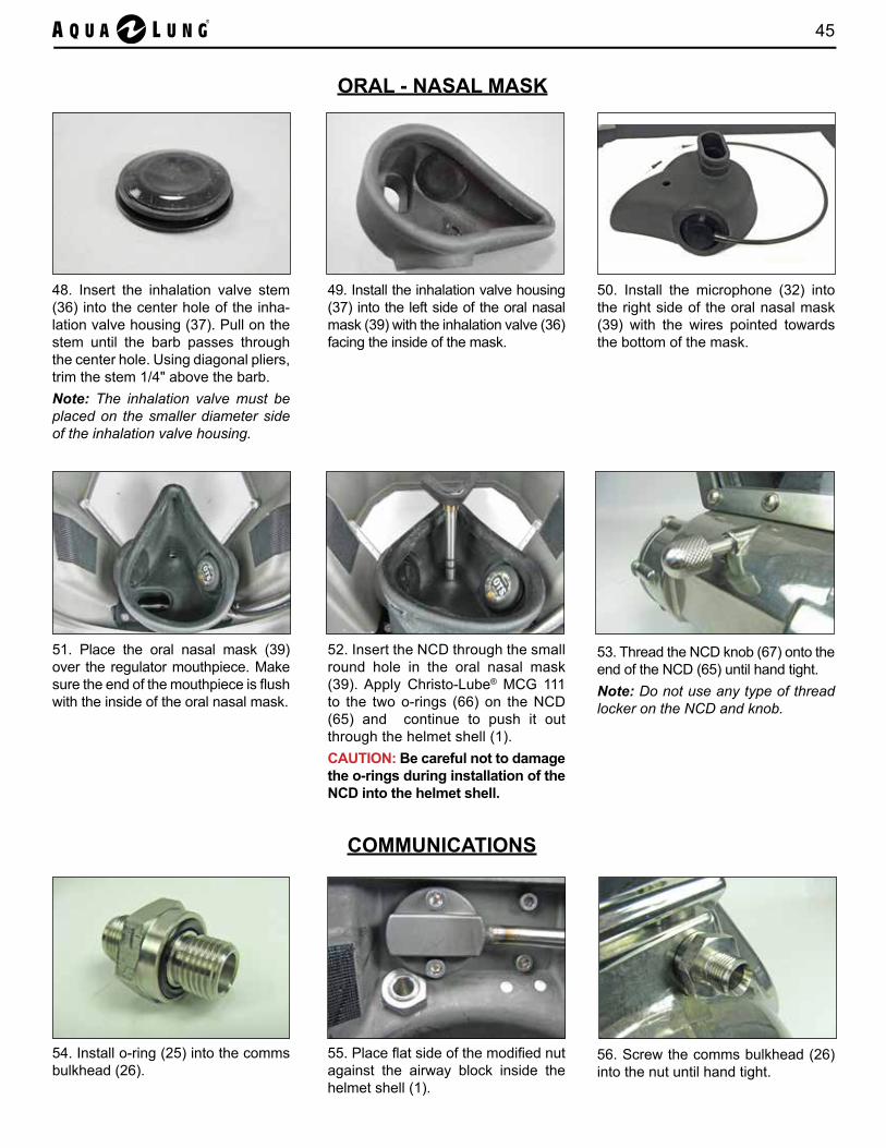
45. Insert the NCD stem (65) through the hole in the nose pad (64) and slide it down to the end (adhesive side first).
46. Fold the nose pad (64) over the metal end of the NCD (65), securing both sides tightly together with the seam on the bottom. Trim the excess nose pad evenly with scissors.
47. Install both o-rings (66) onto the NCD (65).
NOSE CLEARING DEVICE (NCD)
SECOND STAGE REGULATOR The G3000SS Diving Helmet is fitted with the Apeks GX300 Second Stage Regulator (P/N AP0300). Complete service and maintenance instructions for the Apeks GX300 Second Stage Regulator are contained in the separate Apeks document GX300 REGULATOR FOR THE AQUA LUNG G3000SS DIVING HELMET - MAINTENANCE MANUAL.
The above named manual forms part of the formal support documentation for the G3000SS Diving Helmet. It is to be read, and the instructions applied as directed, in conjunction with this manual.
45
COMMUNICATIONS
56. Screw the comms bulkhead (26) into the nut until hand tight.
55. Place flat side of the modified nut against the airway block inside the helmet shell (1).
ORAL - NASAL MASK
49. Install the inhalation valve housing (37) into the left side of the oral nasal mask (39) with the inhalation valve (36) facing the inside of the mask.
50. Install the microphone (32) into the right side of the oral nasal mask (39) with the wires pointed towards the bottom of the mask.
51. Place the oral nasal mask (39) over the regulator mouthpiece. Make sure the end of the mouthpiece is flush with the inside of the oral nasal mask.
52. Insert the NCD through the small round hole in the oral nasal mask (39). Apply Christo-Lube® MCG 111 to the two o-rings (66) on the NCD (65) and continue to push it out through the helmet shell (1).CAUTION: Be careful not to damage the o-rings during installation of the NCD into the helmet shell.
53. Thread the NCD knob (67) onto the end of the NCD (65) until hand tight.Note: Do not use any type of thread locker on the NCD and knob.
54. Install o-ring (25) into the comms bulkhead (26).
48. Insert the inhalation valve stem (36) into the center hole of the inha-lation valve housing (37). Pull on the stem until the barb passes through the center hole. Using diagonal pliers, trim the stem 1/4" above the barb.Note: The inhalation valve must be placed on the smaller diameter side of the inhalation valve housing.
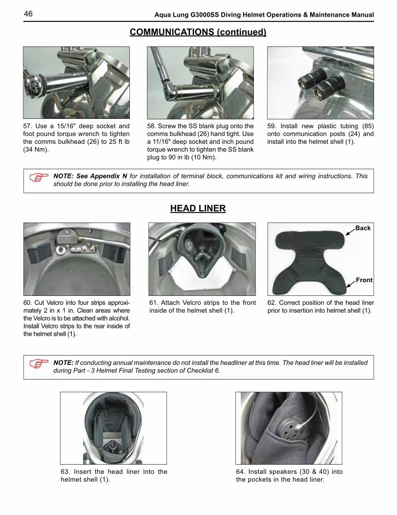
46 Aqua Lung G3000SS Diving Helmet Operations & Maintenance Manual
58. Screw the SS blank plug onto the comms bulkhead (26) hand tight. Use a 11/16" deep socket and inch pound torque wrench to tighten the SS blank plug to 90 in lb (10 Nm).
NOTE: See Appendix N for installation of terminal block, communications kit and wiring instructions. This should be done prior to installing the head liner.
60. Cut Velcro into four strips approxi-mately 2 in x 1 in. Clean areas where the Velcro is to be attached with alcohol. Install Velcro strips to the rear inside of the helmet shell (1).
HEAD LINER
61. Attach Velcro strips to the front inside of the helmet shell (1).
63. Insert the head liner into the helmet shell (1).
COMMUNICATIONS (continued)
57. Use a 15/16" deep socket and foot pound torque wrench to tighten the comms bulkhead (26) to 25 ft lb (34 Nm).
59. Install new plastic tubing (85) onto communication posts (24) and install into the helmet shell (1).
62. Correct position of the head liner prior to insertion into helmet shell (1).
64. Install speakers (30 & 40) into the pockets in the head liner.
Back
Front
NOTE: If conducting annual maintenance do not install the headliner at this time. The head liner will be installed during Part - 3 Helmet Final Testing section of Checklist 6.
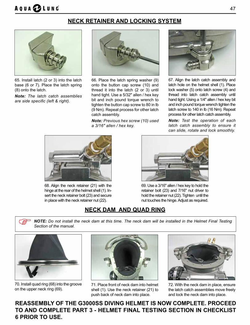
47
69. Use a 3/16" allen / hex key to hold the retainer bolt (23) and 7/16" nut driver to hold the retainer nut (22). Tighten until the nut touches the hinge. Adjust as required.
65. Install latch (2 or 3) into the latch base (6 or 7). Place the latch spring (8) onto the latch.Note: The latch catch assemblies are side specific (left & right).
NECK RETAINER AND LOCKING SYSTEM
72. With the neck dam in place, ensure the latch catch assemblies move freely and lock the neck dam into place.
68. Align the neck retainer (21) with the hinge at the rear of the helmet shell (1). In-sert the neck retainer bolt (23) and secure in place with the neck retainer nut (22).
66. Place the latch spring washer (9) onto the button cap screw (10) and thread it into the latch (2 or 3) until hand tight. Use a 5/32" allen / hex key bit and inch pound torque wrench to tighten the button cap screw to 80 in lb (9 Nm). Repeat process for other latch catch assembly.Note: Previous hex screw (10) used a 3/16" allen / hex key.
70. Install quad ring (68) into the groove on the upper neck ring (69).
NECK DAM AND QUAD RING
67. Align the latch catch assembly and latch hole on the helmet shell (1). Place lock washer (5) onto latch screw (4) and thread into latch catch assembly until hand tight. Using a 1/4" allen / hex key bit and inch pound torque wrench tighten the latch screw to 140 in lb (16 Nm). Repeat process for other latch catch assembly.Note: Test the operation of each latch catch assembly to ensure it can slide, rotate and lock smoothly.
71. Place front of neck dam into helmet shell (1). Use the neck retainer (21) to push back of neck dam into place.
NOTE: Do not install the neck dam at this time. The neck dam will be installed in the Helmet Final Testing Section of the manual.
REASSEMBLY OF THE G3000SS DIVING HELMET IS NOW COMPLETE. PROCEED TO AND COMPLETE PART 3 - HELMET FINAL TESTING SECTION IN CHECKLIST 6 PRIOR TO USE.
48 Aqua Lung G3000SS Diving Helmet Operations & Maintenance Manual
VII. TECHNICIAN CHECK LISTS
Checklist 5 G3000SS Diving Helmet Monthly Inspection and Maintenance Checklist
Checklist 6 G3000SS Diving Helmet Annual Inspection and Maintenance Checklist

49
CHECKLIST 5G3000SS DIVING HELMET
MONTHLY INSPECTION AND MAINTENANCE CHECKLIST
Inspection and maintenance procedures in accordance with this checklist are to be conducted at least once a month for helmets used frequently and once every two months for helmets used less than ten times (i.e. ten dives) in any given month.This checklist is to be used in conjunction with the helmet operations and maintenance manual for guidance in conducting each step in the inspection and maintenance of the G3000SS diving helmet.
NOTE: • The procedures in this checklist are to be performed only by personnel who
have received factory authorized training through an Aqua Lung Service and Repair Seminar.
• If you do not completely understand all of the procedures outlined in this checklist, contact Aqua Lung to speak with a technical advisor before proceeding any further.
• If the helmet is used in contaminated water, monthly inspection and maintenance is required.
• After completing this checklist, it should be kept in the helmet maintenance log/file.
WARNING: Aqua Lung strongly recommends completion of this checklist and meeting the minimum requirements provided before using the G3000SS diving helmet. However, these requirements are not conclusive, as further steps may be required depending on the type of activity performed. FAILURE TO COMPLY WITH THIS CHECKLIST MAY RESULT IN SERIOUS INJURY OR EVEN DEATH.
COMPLETE THE FOLLOWING BOXES PRIOR TO THE CHECKLIST
COMPLETE THE SIGNATURE, DATE AND COMMENTS AT THE END OF THE CHECKLIST
Helmet Serial No: Date:
Diver/Tender:(Print Name)
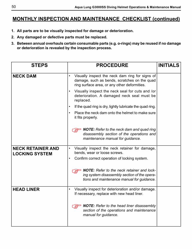
50 Aqua Lung G3000SS Diving Helmet Operations & Maintenance Manual
MONTHLY INSPECTION AND MAINTENANCE CHECKLIST (continued)
1. All parts are to be visually inspected for damage or deterioration. 2. Any damaged or defective parts must be replaced.3. Between annual overhauls certain consumable parts (e.g. o-rings) may be reused if no damage
or deterioration is revealed by the inspection process.
STEPS PROCEDURE INITIALS
NECK DAM
• Visually inspect the neck dam ring for signs of damage, such as bends, scratches on the quad ring surface area, or any other deformities.
• Visually inspect the neck seal for cuts and /or deterioration. A damaged neck seal must be replaced.
• If the quad ring is dry, lightly lubricate the quad ring.
• Place the neck dam onto the helmet to make sure it fits properly.
NOTE: Refer to the neck dam and quad ring disassembly section of the operations and maintenance manual for guidance.
NECK RETAINER AND LOCKING SYSTEM
• Visually inspect the neck retainer for damage, bends, wear or loose screws.
• Confirm correct operation of locking system.
NOTE: Refer to the neck retainer and lock-ing system disassembly section of the opera-tions and maintenance manual for guidance.
HEAD LINER • Visually inspect for deterioration and/or damage. If necessary, replace with new head liner.
NOTE: Refer to the head liner disassembly section of the operations and maintenance manual for guidance.
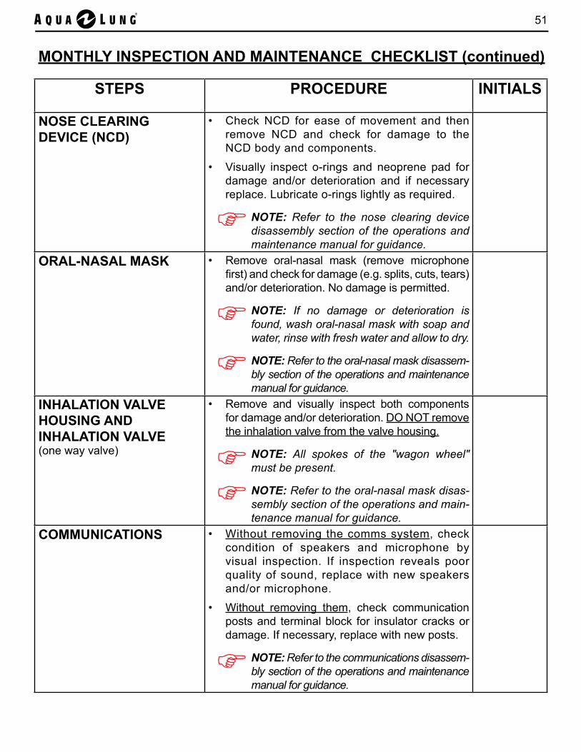
51
MONTHLY INSPECTION AND MAINTENANCE CHECKLIST (continued)
STEPS PROCEDURE INITIALS
NOSE CLEARING DEVICE (NCD)
• Check NCD for ease of movement and then remove NCD and check for damage to the NCD body and components.
• Visually inspect o-rings and neoprene pad for damage and/or deterioration and if necessary replace. Lubricate o-rings lightly as required.
NOTE: Refer to the nose clearing device disassembly section of the operations and maintenance manual for guidance.
ORAL-NASAL MASK • Remove oral-nasal mask (remove microphone first) and check for damage (e.g. splits, cuts, tears) and/or deterioration. No damage is permitted.
NOTE: If no damage or deterioration is found, wash oral-nasal mask with soap and water, rinse with fresh water and allow to dry.
NOTE: Refer to the oral-nasal mask disassem-bly section of the operations and maintenance manual for guidance.
INHALATION VALVE HOUSING AND INHALATION VALVE(one way valve)
• Remove and visually inspect both components for damage and/or deterioration. DO NOT remove the inhalation valve from the valve housing.
NOTE: All spokes of the "wagon wheel" must be present.
NOTE: Refer to the oral-nasal mask disas-sembly section of the operations and main-tenance manual for guidance.
COMMUNICATIONS • Without removing the comms system, check condition of speakers and microphone by visual inspection. If inspection reveals poor quality of sound, replace with new speakers and/or microphone.
• Without removing them, check communication posts and terminal block for insulator cracks or damage. If necessary, replace with new posts.
NOTE: Refer to the communications disassem-bly section of the operations and maintenance manual for guidance.
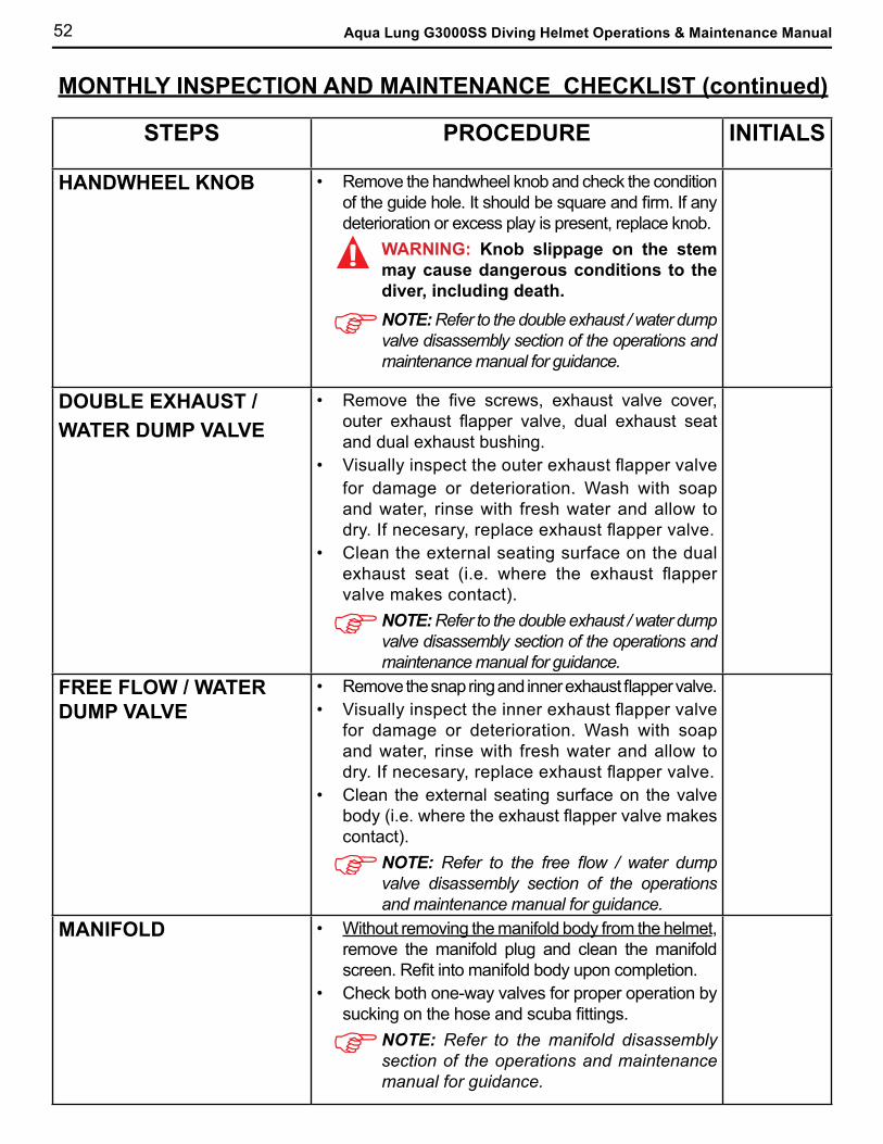
52 Aqua Lung G3000SS Diving Helmet Operations & Maintenance Manual
MONTHLY INSPECTION AND MAINTENANCE CHECKLIST (continued)
STEPS PROCEDURE INITIALS
HANDWHEEL KNOB • Remove the handwheel knob and check the condition of the guide hole. It should be square and firm. If any deterioration or excess play is present, replace knob.
WARNING: Knob slippage on the stem may cause dangerous conditions to the diver, including death.NOTE: Refer to the double exhaust / water dump valve disassembly section of the operations and maintenance manual for guidance.
DOUBLE EXHAUST / WATER DUMP VALVE
• Remove the five screws, exhaust valve cover, outer exhaust flapper valve, dual exhaust seat and dual exhaust bushing.
• Visually inspect the outer exhaust flapper valve for damage or deterioration. Wash with soap and water, rinse with fresh water and allow to dry. If necesary, replace exhaust flapper valve.
• Clean the external seating surface on the dual exhaust seat (i.e. where the exhaust flapper valve makes contact).
NOTE: Refer to the double exhaust / water dump valve disassembly section of the operations and maintenance manual for guidance.
FREE FLOW / WATER DUMP VALVE
• Remove the snap ring and inner exhaust flapper valve.• Visually inspect the inner exhaust flapper valve
for damage or deterioration. Wash with soap and water, rinse with fresh water and allow to dry. If necesary, replace exhaust flapper valve.
• Clean the external seating surface on the valve body (i.e. where the exhaust flapper valve makes contact).
NOTE: Refer to the free flow / water dump valve disassembly section of the operations and maintenance manual for guidance.
MANIFOLD • Without removing the manifold body from the helmet, remove the manifold plug and clean the manifold screen. Refit into manifold body upon completion.
• Check both one-way valves for proper operation by sucking on the hose and scuba fittings.
NOTE: Refer to the manifold disassembly section of the operations and maintenance manual for guidance.
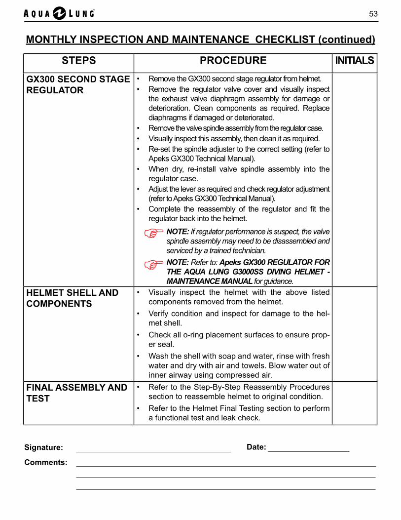
53
MONTHLY INSPECTION AND MAINTENANCE CHECKLIST (continued)
STEPS PROCEDURE INITIALS
GX300 SECOND STAGE REGULATOR
• Remove the GX300 second stage regulator from helmet.• Remove the regulator valve cover and visually inspect
the exhaust valve diaphragm assembly for damage or deterioration. Clean components as required. Replace diaphragms if damaged or deteriorated.
• Remove the valve spindle assembly from the regulator case.• Visually inspect this assembly, then clean it as required.• Re-set the spindle adjuster to the correct setting (refer to
Apeks GX300 Technical Manual).• When dry, re-install valve spindle assembly into the
regulator case.• Adjust the lever as required and check regulator adjustment
(refer to Apeks GX300 Technical Manual).• Complete the reassembly of the regulator and fit the
regulator back into the helmet.
NOTE: If regulator performance is suspect, the valve spindle assembly may need to be disassembled and serviced by a trained technician.NOTE: Refer to: Apeks GX300 REGULATOR FOR THE AQUA LUNG G3000SS DIVING HELMET - MAINTENANCE MANUAL for guidance.
HELMET SHELL AND COMPONENTS
• Visually inspect the helmet with the above listed components removed from the helmet.
• Verify condition and inspect for damage to the hel-met shell.
• Check all o-ring placement surfaces to ensure prop-er seal.
• Wash the shell with soap and water, rinse with fresh water and dry with air and towels. Blow water out of inner airway using compressed air.
FINAL ASSEMBLY AND TEST
• Refer to the Step-By-Step Reassembly Procedures section to reassemble helmet to original condition.
• Refer to the Helmet Final Testing section to perform a functional test and leak check.
Signature: Date:
Comments:

54 Aqua Lung G3000SS Diving Helmet Operations & Maintenance Manual
CHECKLIST 6G3000SS DIVING HELMET
ANNUAL INSPECTION AND MAINTENANCE CHECKLISTInspection and maintenance procedures in accordance with this checklist are to be conducted annually (i.e. Annual Overhaul) unless daily or monthly inspections reveal the need for this to be conducted more frequently.This checklist is to be used in conjunction with the helmet operations and maintenance manual for guidance in conducting each step in the inspection and maintenance of the G3000SS.
NOTE: • The procedures in this checklist are to be performed only by personnel who
have received factory authorized training through an Aqua Lung Service and Repair Seminar.
• If you do not completely understand all of the procedures outlined in this checklist, contact Aqua Lung to speak with a technical advisor before proceeding any further.
• If the helmet is used in contaminated water, monthly inspection and maintenance is required.
• After completing this checklist, it should be kept in the helmet maintenance log/file.
WARNING: Aqua Lung strongly recommends completion of this checklist and meeting the minimum requirements provided before using the G3000SS helmet. However, these requirements are not conclusive, as further steps may be required depending on the type of activity performed. FAILURE TO COMPLY WITH THIS CHECKLIST MAY RESULT IN SERIOUS INJURY OR EVEN DEATH.
GENERAL INSTRUCTIONS1. All parts replaced annually are contained in the annual service kit P/N 400180 or P/N 400183
(See Appendix R). These replacement parts are also identified in Appendices A to G.
2. Any damaged or defective parts must be replaced.
3. All parts should be cleaned and lubricated using the standard procedures detailed in Appendix Q.
TOOLS REQUIRED FOR ANNUAL MAINTENANCE
3/8" Nut Driver Circlip Pliers7/16" Nut Driver Phillips #3 Screwdriver and Screwdriver Bit3/16" Allen / Hex Key and Hex Bit Socket (Torque) 15/16" Deep Socket and Driver or Wrench1/4" Allen / Hex Key and Hex Bit Socket (Torque) 11/16" Deep Socket and Driver5/32" Allen / Hex Key and Hex Bit Socket (Torque) 7/8" Deep Socket and Driver5/8" Flat OE Low Profile / Slim Wrench 5/8" Crowfoot and 3/8" Extension11/16" Flat OE Low Profile / Slim Wrench Torque Screwdriver (20 - 140 inch pounds)O-Ring Tool (Brass or plastic) Torque Wrench (10 - 40 foot pounds)3/8" Flat Blade Screwdriver Soft Jaw Bench ViseDiagonal Pliers Additional tools for the Apeks GX300 Second Stage
Regulator are listed in the separate Apeks document GX300 REGULATOR FOR THE AQUA LUNG G3000SS DIVING HELMET - MAINTENANCE MANUAL.
1/4" Flat Blade Screwdriver and Screwdriver Bit

55
STEPS PROCEDURE INITIALS
NECK DAM AND QUAD RINGNOTE: Refer to the neck dam and quad ring disassembly section of the operations and maintenance manual for guidance.
CHIN STRAP
• Visually inspect for tears and cuts. • Replace if damaged or defective.• Check that all screws are present and secure.
QUAD RING • Remove and inspect for cuts and/or deterioration.
• If necessary, replace the quad ring.
NOTE: The quad ring has a long service life and is not normally replaced annually.
NECK SEAL • Visually inspect for cuts and/or deterioration.• If necessary, replace the neck seal.
UPPER NECK RING • Visually inspect the o-ring groove for damage.
BOTTOM NECK RING • Visually inspect for damage. Check that all screws are present and secure.
COMPLETE THE FOLLOWING BOXES PRIOR TO THE CHECKLIST
COMPLETE THE SIGNATURE, DATE AND COMMENTS AT THE END OF THE CHECKLIST
Helmet Serial No: Date:
Technician:(Print Name)
ANNUAL INSPECTION AND MAINTENANCE CHECKLIST (continued)
PART 1 - HELMET DISASSEMBLYFollow Section VI - Step-By-Step Disassembly / Reassembly Procedures along with this Annual Inspection and Maintenance Checklist to disassemble the helmet for annual service and inspection.
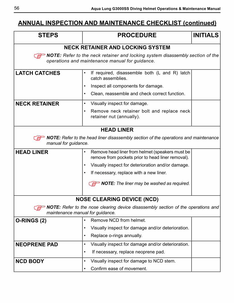
56 Aqua Lung G3000SS Diving Helmet Operations & Maintenance Manual
ANNUAL INSPECTION AND MAINTENANCE CHECKLIST (continued)
STEPS PROCEDURE INITIALS
NECK RETAINER AND LOCKING SYSTEMNOTE: Refer to the neck retainer and locking system disassembly section of the operations and maintenance manual for guidance.
LATCH CATCHES • If required, disassemble both (L and R) latch catch assemblies.
• Inspect all components for damage.
• Clean, reassemble and check correct function.
NECK RETAINER • Visually inspect for damage.
• Remove neck retainer bolt and replace neck retainer nut (annually).
HEAD LINERNOTE: Refer to the head liner disassembly section of the operations and maintenance manual for guidance.
HEAD LINER • Remove head liner from helmet (speakers must be remove from pockets prior to head liner removal).
• Visually inspect for deterioration and/or damage.
• If necessary, replace with a new liner.
NOTE: The liner may be washed as required.
NOSE CLEARING DEVICE (NCD)NOTE: Refer to the nose clearing device disassembly section of the operations and maintenance manual for guidance.
O-RINGS (2) • Remove NCD from helmet.
• Visually inspect for damage and/or deterioration.
• Replace o-rings annually.
NEOPRENE PAD • Visually inspect for damage and/or deterioration.
• If necessary, replace neoprene pad.
NCD BODY • Visually inspect for damage to NCD stem.
• Confirm ease of movement.
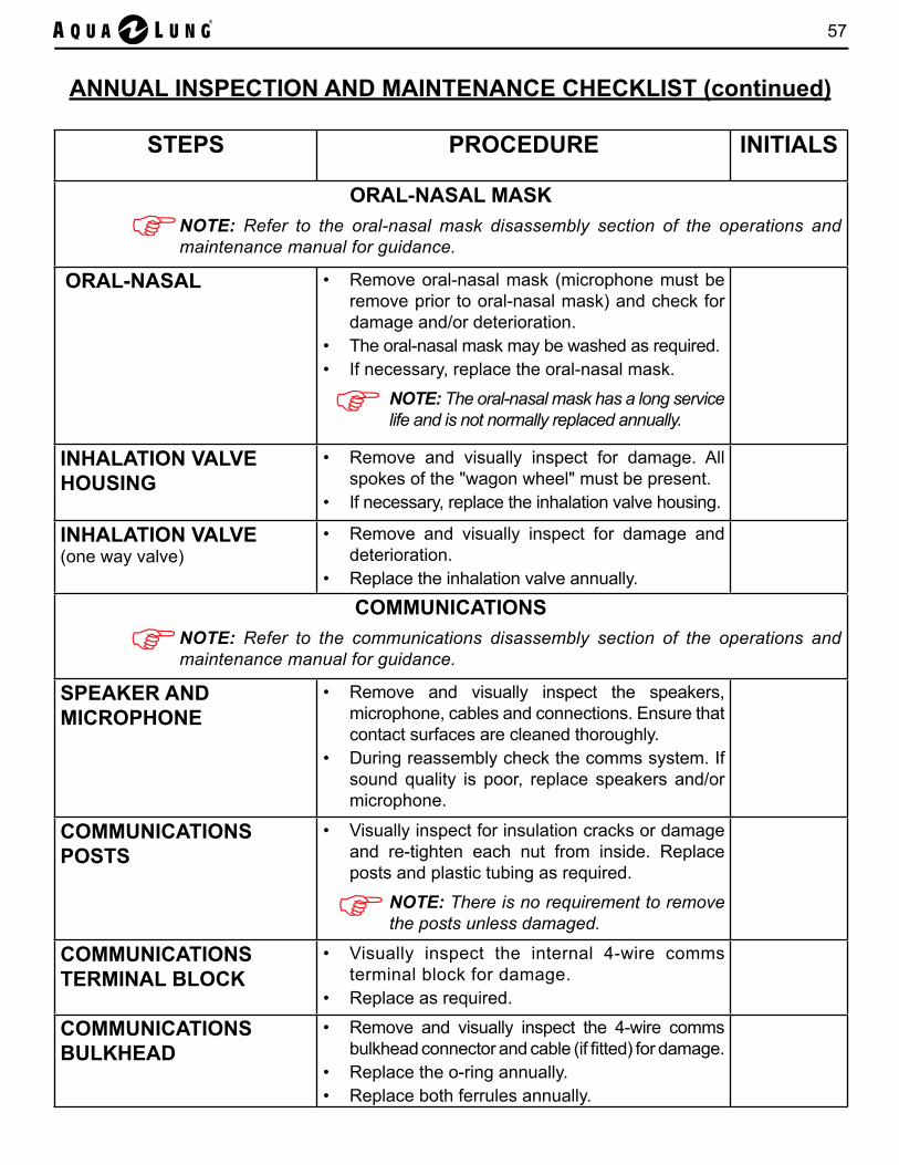
57
ANNUAL INSPECTION AND MAINTENANCE CHECKLIST (continued)
STEPS PROCEDURE INITIALS
ORAL-NASAL MASKNOTE: Refer to the oral-nasal mask disassembly section of the operations and maintenance manual for guidance.
ORAL-NASAL • Remove oral-nasal mask (microphone must be remove prior to oral-nasal mask) and check for damage and/or deterioration.
• The oral-nasal mask may be washed as required. • If necessary, replace the oral-nasal mask.
NOTE: The oral-nasal mask has a long service life and is not normally replaced annually.
INHALATION VALVE HOUSING
• Remove and visually inspect for damage. All spokes of the "wagon wheel" must be present.
• If necessary, replace the inhalation valve housing.
INHALATION VALVE(one way valve)
• Remove and visually inspect for damage and deterioration.
• Replace the inhalation valve annually.
COMMUNICATIONSNOTE: Refer to the communications disassembly section of the operations and maintenance manual for guidance.
SPEAKER AND MICROPHONE
• Remove and visually inspect the speakers, microphone, cables and connections. Ensure that contact surfaces are cleaned thoroughly.
• During reassembly check the comms system. If sound quality is poor, replace speakers and/or microphone.
COMMUNICATIONS POSTS
• Visually inspect for insulation cracks or damage and re-tighten each nut from inside. Replace posts and plastic tubing as required.
NOTE: There is no requirement to remove the posts unless damaged.
COMMUNICATIONS TERMINAL BLOCK
• Visually inspect the internal 4-wire comms terminal block for damage.
• Replace as required.
COMMUNICATIONS BULKHEAD
• Remove and visually inspect the 4-wire comms bulkhead connector and cable (if fitted) for damage.
• Replace the o-ring annually. • Replace both ferrules annually.
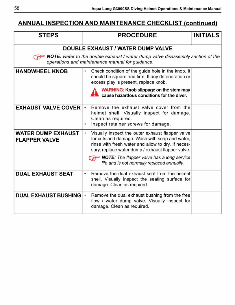
58 Aqua Lung G3000SS Diving Helmet Operations & Maintenance Manual
ANNUAL INSPECTION AND MAINTENANCE CHECKLIST (continued)
STEPS PROCEDURE INITIALS
DOUBLE EXHAUST / WATER DUMP VALVENOTE: Refer to the double exhaust / water dump valve disassembly section of the operations and maintenance manual for guidance.
HANDWHEEL KNOB • Check condition of the guide hole in the knob. It should be square and firm. If any deterioration or excess play is present, replace knob.
WARNING: Knob slippage on the stem may cause hazardous conditions for the diver.
EXHAUST VALVE COVER • Remove the exhaust valve cover from the helmet shell. Visually inspect for damage. Clean as required.
• Inspect retainer screws for damage.
WATER DUMP EXHAUST FLAPPER VALVE
• Visually inspect the outer exhaust flapper valve for cuts and damage. Wash with soap and water, rinse with fresh water and allow to dry. If neces-sary, replace water dump / exhaust flapper valve.
NOTE: The flapper valve has a long service life and is not normally replaced annually.
DUAL EXHAUST SEAT • Remove the dual exhaust seat from the helmet shell. Visually inspect the seating surface for damage. Clean as required.
DUAL EXHAUST BUSHING • Remove the dual exhaust bushing from the free flow / water dump valve. Visually inspect for damage. Clean as required.
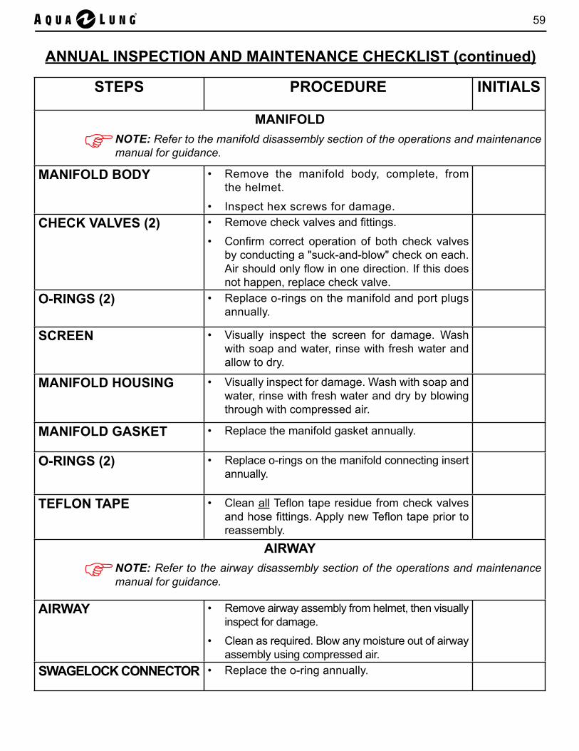
59
ANNUAL INSPECTION AND MAINTENANCE CHECKLIST (continued)
STEPS PROCEDURE INITIALS
MANIFOLDNOTE: Refer to the manifold disassembly section of the operations and maintenance manual for guidance.
MANIFOLD BODY
• Remove the manifold body, complete, from the helmet.
• Inspect hex screws for damage.CHECK VALVES (2) • Remove check valves and fittings.
• Confirm correct operation of both check valves by conducting a "suck-and-blow" check on each. Air should only flow in one direction. If this does not happen, replace check valve.
O-RINGS (2) • Replace o-rings on the manifold and port plugs annually.
SCREEN • Visually inspect the screen for damage. Wash with soap and water, rinse with fresh water and allow to dry.
MANIFOLD HOUSING • Visually inspect for damage. Wash with soap and water, rinse with fresh water and dry by blowing through with compressed air.
MANIFOLD GASKET • Replace the manifold gasket annually.
O-RINGS (2) • Replace o-rings on the manifold connecting insert annually.
TEFLON TAPE • Clean all Teflon tape residue from check valves and hose fittings. Apply new Teflon tape prior to reassembly.
AIRWAYNOTE: Refer to the airway disassembly section of the operations and maintenance manual for guidance.
AIRWAY • Remove airway assembly from helmet, then visually inspect for damage.
• Clean as required. Blow any moisture out of airway assembly using compressed air.
SWAGELOCK CONNECTOR • Replace the o-ring annually.
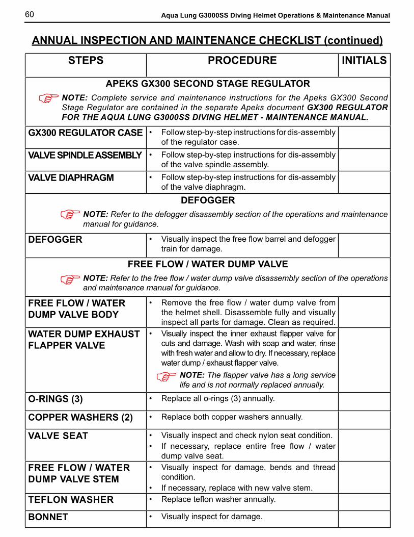
60 Aqua Lung G3000SS Diving Helmet Operations & Maintenance Manual
ANNUAL INSPECTION AND MAINTENANCE CHECKLIST (continued)
STEPS PROCEDURE INITIALS
APEKS GX300 SECOND STAGE REGULATORNOTE: Complete service and maintenance instructions for the Apeks GX300 Second Stage Regulator are contained in the separate Apeks document GX300 REGULATOR FOR THE AQUA LUNG G3000SS DIVING HELMET - MAINTENANCE MANUAL.
GX300 REGULATOR CASE • Follow step-by-step instructions for dis-assembly of the regulator case.
VALVE SPINDLE ASSEMBLY • Follow step-by-step instructions for dis-assembly of the valve spindle assembly.
VALVE DIAPHRAGM • Follow step-by-step instructions for dis-assembly of the valve diaphragm.
DEFOGGERNOTE: Refer to the defogger disassembly section of the operations and maintenance manual for guidance.
DEFOGGER • Visually inspect the free flow barrel and defogger train for damage.
FREE FLOW / WATER DUMP VALVENOTE: Refer to the free flow / water dump valve disassembly section of the operations and maintenance manual for guidance.
FREE FLOW / WATER DUMP VALVE BODY
• Remove the free flow / water dump valve from the helmet shell. Disassemble fully and visually inspect all parts for damage. Clean as required.
WATER DUMP EXHAUST FLAPPER VALVE
• Visually inspect the inner exhaust flapper valve for cuts and damage. Wash with soap and water, rinse with fresh water and allow to dry. If necessary, replace water dump / exhaust flapper valve.
NOTE: The flapper valve has a long service life and is not normally replaced annually.
O-RINGS (3) • Replace all o-rings (3) annually.
COPPER WASHERS (2) • Replace both copper washers annually.
VALVE SEAT • Visually inspect and check nylon seat condition. • If necessary, replace entire free flow / water
dump valve seat.FREE FLOW / WATER DUMP VALVE STEM
• Visually inspect for damage, bends and thread condition.
• If necessary, replace with new valve stem.TEFLON WASHER • Replace teflon washer annually.
BONNET • Visually inspect for damage.

61
ANNUAL INSPECTION AND MAINTENANCE CHECKLIST (continued)
STEPS PROCEDURE INITIALSFACE PORT
NOTE: Refer to the face port disassembly section of the operations and mainte-nance manual for guidance.
PORT RETAINER • Visually inspect the port retainer and screws for damage.
• Clean as required.O-RING (1)
• Visually inspect the groove for damage and clean as required.
• Replace the o-ring annually.
FACE PORT • Check condition of the face port. • If necessary, wash with soap and water, rinse with
fresh water and allow to dry. • Replace the face port if damaged.
NOTE: DO NOT scrub, use aerosol or chemicals on the face port, it will weaken it.
HELMET SHELL• Verify condition and inspect for damage to the helmet shell.
• Clean as required with soap and water, rinse with fresh water, and dry.
• Blow any moisture out of airway assembly using compressed air.
Technician Comments (e.g. Specific items noted during maintenance):
Comments:
Signature: Date:
DISASSEMBLY OF THE G3000SS DIVING HELMET IS NOW COMPLETE. PROCEED TO PART 2 OF THE CHECKLIST FOR REASSEMBLY.
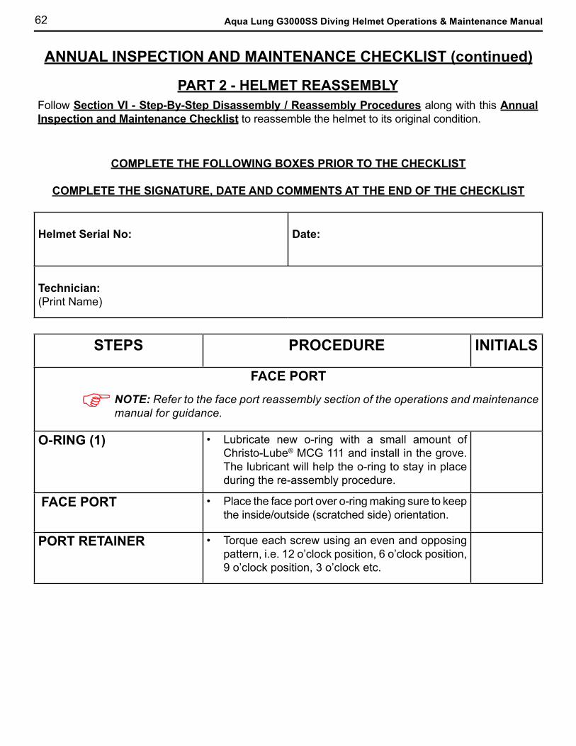
62 Aqua Lung G3000SS Diving Helmet Operations & Maintenance Manual
ANNUAL INSPECTION AND MAINTENANCE CHECKLIST (continued)
PART 2 - HELMET REASSEMBLYFollow Section VI - Step-By-Step Disassembly / Reassembly Procedures along with this Annual Inspection and Maintenance Checklist to reassemble the helmet to its original condition.
COMPLETE THE FOLLOWING BOXES PRIOR TO THE CHECKLIST
COMPLETE THE SIGNATURE, DATE AND COMMENTS AT THE END OF THE CHECKLIST
Helmet Serial No: Date:
Technician:(Print Name)
STEPS PROCEDURE INITIALS
FACE PORTNOTE: Refer to the face port reassembly section of the operations and maintenance manual for guidance.
O-RING (1) • Lubricate new o-ring with a small amount of Christo-Lube® MCG 111 and install in the grove. The lubricant will help the o-ring to stay in place during the re-assembly procedure.
FACE PORT • Place the face port over o-ring making sure to keep the inside/outside (scratched side) orientation.
PORT RETAINER • Torque each screw using an even and opposing pattern, i.e. 12 o’clock position, 6 o’clock position, 9 o’clock position, 3 o’clock etc.
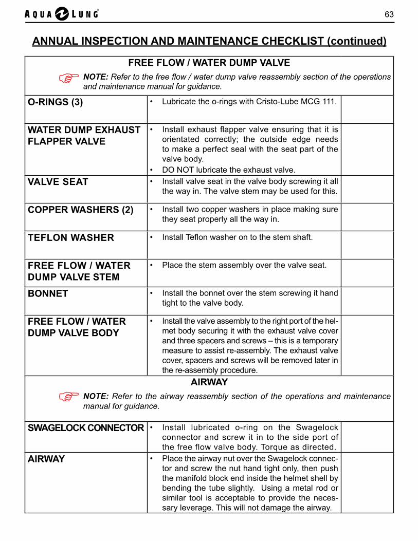
63
FREE FLOW / WATER DUMP VALVENOTE: Refer to the free flow / water dump valve reassembly section of the operations and maintenance manual for guidance.
O-RINGS (3) • Lubricate the o-rings with Cristo-Lube MCG 111.
WATER DUMP EXHAUST FLAPPER VALVE
• Install exhaust flapper valve ensuring that it is orientated correctly; the outside edge needs to make a perfect seal with the seat part of the valve body.
• DO NOT lubricate the exhaust valve. VALVE SEAT • Install valve seat in the valve body screwing it all
the way in. The valve stem may be used for this.
COPPER WASHERS (2) • Install two copper washers in place making sure they seat properly all the way in.
TEFLON WASHER • Install Teflon washer on to the stem shaft.
FREE FLOW / WATER DUMP VALVE STEM
• Place the stem assembly over the valve seat.
BONNET • Install the bonnet over the stem screwing it hand tight to the valve body.
FREE FLOW / WATER DUMP VALVE BODY
• Install the valve assembly to the right port of the hel-met body securing it with the exhaust valve cover and three spacers and screws – this is a temporary measure to assist re-assembly. The exhaust valve cover, spacers and screws will be removed later in the re-assembly procedure.
AIRWAYNOTE: Refer to the airway reassembly section of the operations and maintenance manual for guidance.
SWAGELOCK CONNECTOR • Install lubricated o-ring on the Swagelock connector and screw it in to the side port of the free flow valve body. Torque as directed.
AIRWAY • Place the airway nut over the Swagelock connec-tor and screw the nut hand tight only, then push the manifold block end inside the helmet shell by bending the tube slightly. Using a metal rod or similar tool is acceptable to provide the neces-sary leverage. This will not damage the airway.
ANNUAL INSPECTION AND MAINTENANCE CHECKLIST (continued)
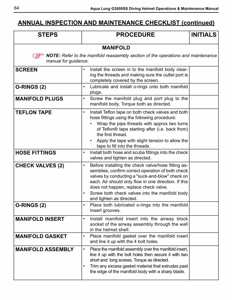
64 Aqua Lung G3000SS Diving Helmet Operations & Maintenance Manual
STEPS PROCEDURE INITIALS
MANIFOLDNOTE: Refer to the manifold reassembly section of the operations and maintenance manual for guidance.
SCREEN • Install the screen in to the manifold body clear-ing the threads and making sure the outlet port is completely covered by the screen.
O-RINGS (2) • Lubricate and install o-rings onto both manifold plugs.
MANIFOLD PLUGS • Screw the manifold plug and port plug to the manifold body. Torque both as directed.
TEFLON TAPE • Install Teflon tape on both check valves and both hose fittings using the following procedure:• Wrap the pipe threads with approx two turns
of Teflon® tape starting after (i.e. back from) the first thread.
• Apply the tape with slight tension to allow the tape to fill into the threads.
HOSE FITTINGS • Install both hose and scuba fittings into the check valves and tighten as directed.
CHECK VALVES (2) • Before installing the check valve/hose fitting as-semblies, confirm correct operation of both check valves by conducting a "suck-and-blow" check on each. Air should only flow in one direction. If this does not happen, replace check valve.
• Screw both check valves into the manifold body and tighten as directed.
O-RINGS (2) • Place both lubricated o-rings into the manifold Insert grooves.
MANIFOLD INSERT • Install manifold insert into the airway block socket of the airway assembly through the wall in the helmet shell.
MANIFOLD GASKET • Place manifold gasket over the manifold insert and line it up with the 4 bolt holes.
MANIFOLD ASSEMBLY • Place the manifold assembly over the manifold insert, line it up with the bolt holes then secure it with two short and long screws. Torque as directed.
• Trim any excess gasket material that extrudes past the edge of the manifold body with a sharp blade.
ANNUAL INSPECTION AND MAINTENANCE CHECKLIST (continued)
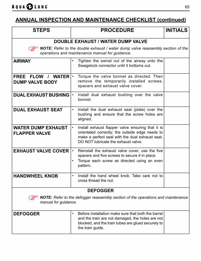
65
ANNUAL INSPECTION AND MAINTENANCE CHECKLIST (continued)
STEPS PROCEDURE INITIALS
DOUBLE EXHAUST / WATER DUMP VALVENOTE: Refer to the double exhaust / water dump valve reassembly section of the operations and maintenance manual for guidance.
AIRWAY • Tighten the swivel nut of the airway onto the Swagelock connector until it bottoms out.
FREE FLOW / WATER DUMP VALVE BODY
• Torque the valve bonnet as directed. Then remove the temporarily installed screws, spacers and exhaust valve cover.
DUAL EXHAUST BUSHING • Install dual exhaust bushing over the valve bonnet.
DUAL EXHAUST SEAT • Install the dual exhaust seat (plate) over the bushing and ensure that the screw holes are aligned.
WATER DUMP EXHAUST FLAPPER VALVE
• Install exhaust flapper valve ensuring that it is orientated correctly; the outside edge needs to make a perfect seal with the dual exhaust seat. DO NOT lubricate the exhaust valve.
EXHAUST VALVE COVER • Reinstall the exhaust valve cover, use the five spacers and five screws to secure it in place.
• Torque each screw as directed using an even pattern.
HANDWHEEL KNOB • Install the hand wheel knob. Take care not to cross thread the nut.
DEFOGGERNOTE: Refer to the defogger reassembly section of the operations and maintenance manual for guidance.
DEFOGGER • Before installation make sure that both the barrel and the train are not damaged, the holes are not blocked, and the train tubes are glued securely to the train guide.
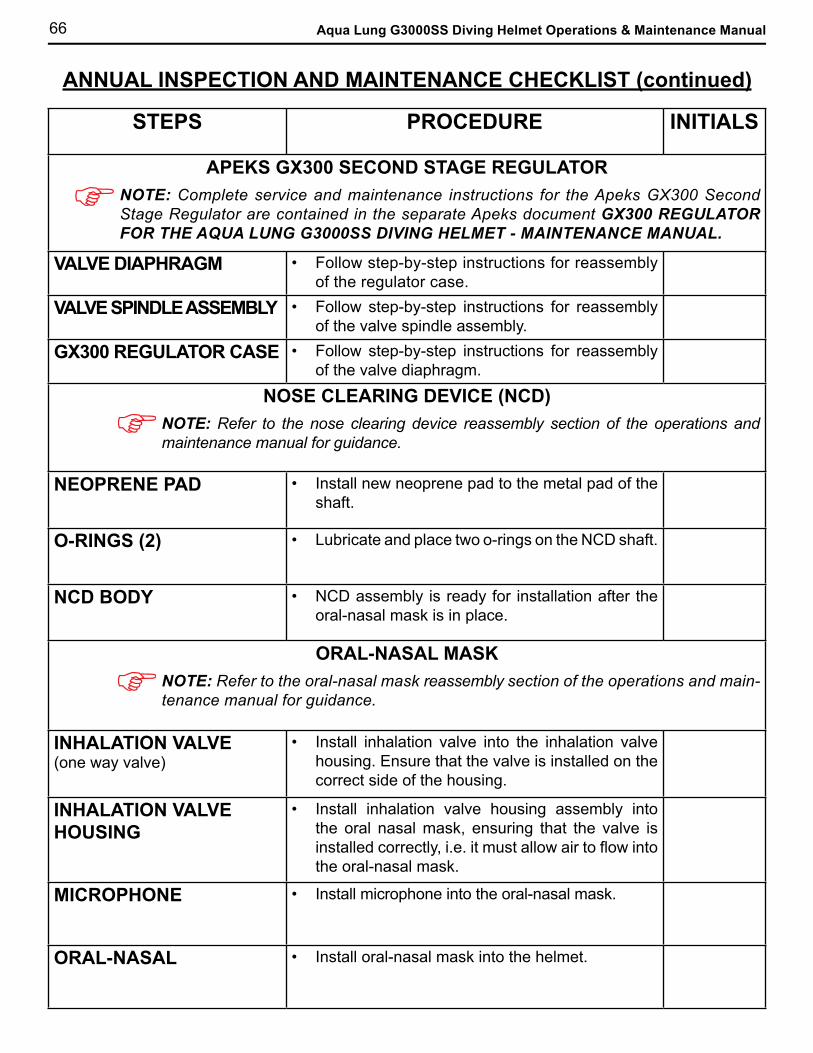
66 Aqua Lung G3000SS Diving Helmet Operations & Maintenance Manual
STEPS PROCEDURE INITIALS
APEKS GX300 SECOND STAGE REGULATORNOTE: Complete service and maintenance instructions for the Apeks GX300 Second Stage Regulator are contained in the separate Apeks document GX300 REGULATOR FOR THE AQUA LUNG G3000SS DIVING HELMET - MAINTENANCE MANUAL.
VALVE DIAPHRAGM • Follow step-by-step instructions for reassembly of the regulator case.
VALVE SPINDLE ASSEMBLY • Follow step-by-step instructions for reassembly of the valve spindle assembly.
GX300 REGULATOR CASE • Follow step-by-step instructions for reassembly of the valve diaphragm.
NOSE CLEARING DEVICE (NCD)NOTE: Refer to the nose clearing device reassembly section of the operations and maintenance manual for guidance.
NEOPRENE PAD • Install new neoprene pad to the metal pad of the shaft.
O-RINGS (2) • Lubricate and place two o-rings on the NCD shaft.
NCD BODY • NCD assembly is ready for installation after the oral-nasal mask is in place.
ORAL-NASAL MASKNOTE: Refer to the oral-nasal mask reassembly section of the operations and main-tenance manual for guidance.
INHALATION VALVE(one way valve)
• Install inhalation valve into the inhalation valve housing. Ensure that the valve is installed on the correct side of the housing.
INHALATION VALVE HOUSING
• Install inhalation valve housing assembly into the oral nasal mask, ensuring that the valve is installed correctly, i.e. it must allow air to flow into the oral-nasal mask.
MICROPHONE • Install microphone into the oral-nasal mask.
ORAL-NASAL • Install oral-nasal mask into the helmet.
ANNUAL INSPECTION AND MAINTENANCE CHECKLIST (continued)

67
ANNUAL INSPECTION AND MAINTENANCE CHECKLIST (continued)
STEPS PROCEDURE INITIALS
COMMUNICATIONSNOTE: Refer to the communications reassembly section of the operations and main-tenance manual for guidance.
COMMUNICATIONS BULKHEAD
• Install a lubricated o-ring onto the comms bulkhead, then screw the bulkhead into the modified nut in the inside of the helmet shell. Torque as directed.
• When fitting a 4-wire comms cable, a small quantity of household dishwashing detergent applied to the outside of the cable will help the ferrules to slide along the cable.
COMMUNICATIONS POSTS
• Install the communication posts with plastic tubing into the helmet shell.
COMMUNICATIONS TERMINAL BLOCK
• Install the communication terminal block over the communication posts.
SPEAKER AND MICROPHONE
• Install speakers and microphone wire connectors to the terminal block.
HEAD LINERNOTE: Refer to the head liner reassembly section of the operations and maintenance manual for guidance.
HEAD LINER • When correctly positioned the front edges of the headliner should be just touching the oral-nasal mask. The headliner should always be pre-adjusted by the diver.
NECK RETAINER AND LOCKING SYSTEMNOTE: Refer to the neck retainer and locking system reassembly section of the operations and maintenance manual for guidance.
LATCH CATCHES • If removed for maintenance, reinstall left and right latch catches. Torque the screws as directed.
• Check the correct operation of the latch catches after re-assembly.
NECK RETAINER • Check that the neck retainer is not bent before installation. A bent neck retainer may be straightened in a vise.

68 Aqua Lung G3000SS Diving Helmet Operations & Maintenance Manual
ANNUAL INSPECTION AND MAINTENANCE CHECKLIST (continued)
Technician Comments (e.g. Specific items noted during maintenance):
Comments:
Signature: Date:
REASSEMBLY OF THE G3000SS DIVING HELMET IS NOW COMPLETE. PROCEED TO PART 3 OF THE CHECKLIST AND COMPLETE HELMET FINAL TESTING PRIOR TO USE.
STEPS PROCEDURE INITIALSNECK DAM AND QUAD RING
NOTE: Refer to the neck dam and quad ring reassembly section of the operations and maintenance manual for guidance.
NECK DAM AND QUAD RING
Re-installation during annual maintenance:• Check the condition of the neck seal. Replace as
necessary (see below).• Install a lightly lubricated quad ring into the
groove in the upper neck ring.NOTE: The quad ring has a long service life and is not normally replaced annually.
• Install the chin strap. Torque screws as directed.NEOPRENE NECK SEAL REPLACEMENT
UPPER NECK RING • Blow through all threads with compressed air to ensure that there is no debris inside them.
• Position the upper neck ring with the holes facing up.• Place the neck seal (with the seam tape on the inside)
on top of the upper neck ring and line up the holes.BOTTOM NECK RING • Place the side of the lower neck ring with the
screw marks face up over the neoprene neck seal and line up the holes.
• Apply a small amount of Christo-Lube® MCG 111 through each hole in the neoprene neck seal (or to each screw) to make sure the screws do not bind with the neoprene during installation.
• Starting with two screws, front and back, insert screws all the way around until all screws are in place. Torque all screws as directed.
NECK SEAL • Trim any excess neoprene after all screws are tight and torqued correctly.
• Since neoprene compresses, the torque on each screw should be rechecked after 24 hours.
• Turn neck seal rightside out.QUAD RING • Install lubricated quad ring into the groove on the
upper neck ring.
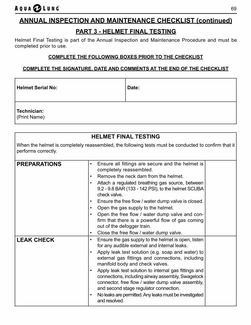
69
HELMET FINAL TESTINGWhen the helmet is completely reassembled, the following tests must be conducted to confirm that it performs correctly.
PREPARATIONS
• Ensure all fittings are secure and the helmet is completely reassembled.
• Remove the neck dam from the helmet.• Attach a regulated breathing gas source, between
9.2 - 9.8 BAR (133 - 142 PSI), to the helmet SCUBA check valve.
• Ensure the free flow / water dump valve is closed.• Open the gas supply to the helmet.• Open the free flow / water dump valve and con-
firm that there is a powerful flow of gas coming out of the defogger train.
• Close the free flow / water dump valve.LEAK CHECK • Ensure the gas supply to the helmet is open, listen
for any audible external and internal leaks.• Apply leak test solution (e.g. soap and water) to
external gas fittings and connections, including manifold body and check valves.
• Apply leak test solution to internal gas fittings and connections, including airway assembly, Swagelock connector, free flow / water dump valve assembly, and second stage regulator connection.
• No leaks are permitted. Any leaks must be investigated and resolved.
ANNUAL INSPECTION AND MAINTENANCE CHECKLIST (continued)
COMPLETE THE FOLLOWING BOXES PRIOR TO THE CHECKLIST
COMPLETE THE SIGNATURE, DATE AND COMMENTS AT THE END OF THE CHECKLIST
Helmet Serial No: Date:
Technician:(Print Name)
PART 3 - HELMET FINAL TESTINGHelmet Final Testing is part of the Annual Inspection and Maintenance Procedure and must be completed prior to use.
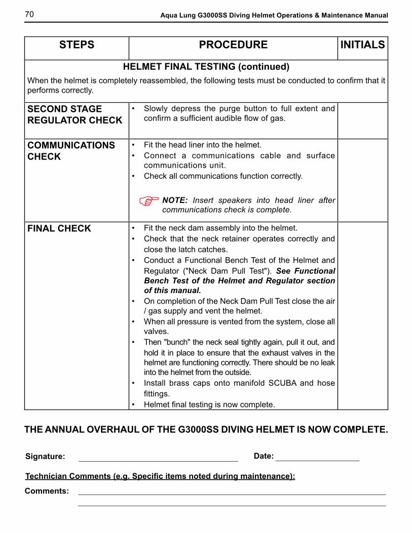
70 Aqua Lung G3000SS Diving Helmet Operations & Maintenance Manual
STEPS PROCEDURE INITIALS
HELMET FINAL TESTING (continued)When the helmet is completely reassembled, the following tests must be conducted to confirm that it performs correctly.
SECOND STAGE REGULATOR CHECK
• Slowly depress the purge button to full extent and confirm a sufficient audible flow of gas.
COMMUNICATIONS CHECK
• Fit the head liner into the helmet.• Connect a communications cable and surface
communications unit.• Check all communications function correctly.
NOTE: Insert speakers into head liner after communications check is complete.
FINAL CHECK • Fit the neck dam assembly into the helmet.• Check that the neck retainer operates correctly and
close the latch catches.• Conduct a Functional Bench Test of the Helmet and
Regulator ("Neck Dam Pull Test"). See Functional Bench Test of the Helmet and Regulator section of this manual.
• On completion of the Neck Dam Pull Test close the air / gas supply and vent the helmet.
• When all pressure is vented from the system, close all valves.
• Then "bunch" the neck seal tightly again, pull it out, and hold it in place to ensure that the exhaust valves in the helmet are functioning correctly. There should be no leak into the helmet from the outside.
• Install brass caps onto manifold SCUBA and hose fittings.
• Helmet final testing is now complete.
Technician Comments (e.g. Specific items noted during maintenance):
Comments:
Signature: Date:
THE ANNUAL OVERHAUL OF THE G3000SS DIVING HELMET IS NOW COMPLETE.

71
1. Connect a regulated air source between 9.2 BAR (133 PSI) and 9.8 BAR (142 PSI) to the helmet.
FUNCTIONAL BENCH TEST OF THE HELMET AND REGULATOR("NECK DAM PULL TEST")
3. Slowly pull the bunched end of the neck seal out to full extension, then push back fully into the helmet. Repeat this 3 or 4 times. The regulator should be heard to open and close (i.e. inhale and exhale). This pull and push action simulates a div-er breathing in the helmet. A properly serviced and adjusted regulator should deliver air upon deep inhalation without excessive inhalation effort, free flow or "fluttering" of the second stage.
2. Take hold of the open end of the neck seal and "bunch" tightly to ensure that the open end is "sealed".

72 Aqua Lung G3000SS Diving Helmet Operations & Maintenance Manual
VIII. APPENDICES
Appendix A Main Assemblies
Appendix B Inner Components
Appendix C Manifold Body
Appendix D Free Flow / Water Dump Valve
Appendix E Second Stage Regulator
Appendix F Nose Clearing Device (NCD)
Appendix G Neck Dam
Appendix H Welding Shield Kit
Appendix I Welding Shield Assembly Installation Instructions
Appendix J Free Flow Plug Insert Kit Installation Instructions
Appendix K Camera / Light Bracket Installation Instructions
Appendix L Terminal Block Communications Kits
Appendix M Twist-On Communications Kits
Appendix N Communications Kit Installation Instructions
Appendix O Torque Specifications
Appendix P Recommended Cleaners and Lubricants
Appendix Q Cleaning and Lubricating
Appendix R Annual Service Kit
Appendix S Field Spares Kit
Appendix T Maintenance Log Sheet
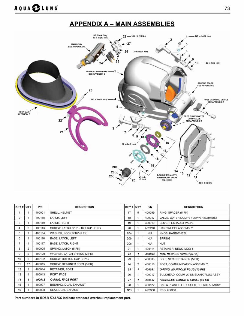
73
APPENDIX A – MAIN ASSEMBLIES
KEY # QTY P/N DESCRIPTION
1 1 400001 SHELL, HELMET
2 1 400118 LATCH, LEFT
3 1 400119 LATCH, RIGHT
4 2 400113 SCREW, LATCH 5/16" - 18 X 3/4" LONG
5 2 400134 WASHER, LOCK 5/16" (5 PK)
6 1 400116 BASE, LATCH, LEFT
7 1 400117 BASE, LATCH, RIGHT
8 2 400005 SPRING, LATCH (5 PK)
9 2 400120 WASHER, LATCH SPRING (2 PK)
10 2 400192 SCREW, BUTTON CAP (5 PK)
11 17 400015 SCREW, RETAINER PORT (5 PK)
12 1 400014 RETAINER, PORT
13 1 400013 PORT, FACE
14 1 400012 O-RING, FACE PORT
15 1 400097 BUSHING, DUAL EXHAUST
16 1 400098 SEAT, DUAL EXHAUST
KEY # QTY P/N DESCRIPTION
17 5 400099 RING, SPACER (5 PK)
18 1 400047 VALVE, WATER DUMP / FLAPPER EXHAUST
19 1 400010 COVER, EXHAUST VALVE
20 1 AP0270 HANDWHEEL ASSEMBLY
20a 1 N/A KNOB, HANDWHEEL
20b 1 N/A SPRING
20c 1 N/A NUT
21 1 400114 RETAINER, NECK, MOD 1
22 1 400004 NUT, NECK RETAINER (5 PK)
23 1 400003 BOLT, NECK RETAINER (5 PK)
24 2 400016 POST, COMMUNICATION ASSEMBLY
25 1 400031 O-RING, MANIFOLD PLUG (10 PK)
26 1 400017 BULKHEAD, COMM W/ SS BLANK PLUG ASSY
27 1 400127 FERRULES, LARGE & SMALL (10 pk)
28 1 400122 CAP & PLASTIC FERRULES, BULKHEAD ASSY
N/S 1 AP0300 REG, GX300
Part numbers in BOLD ITALICS indicate standard overhaul replacement part.
INNER COMPONENTS SEE APPENDIX B
NECK DAM APPENDIX G
MANIFOLD SEE APPENDIX C
SECOND STAGE SEE APPENDIX E
NOSE CLEARING DEVICE SEE APPENDIX F
FREE FLOW / WATER DUMP VALVE
SEE APPENDIX D
DOUBLE EXHAUST / WATER DUMP VALVE
PN 400111
1
6
7
5
42
3
89
10
8 9 10
11121314
15
1617
18
19
11
20
21
22
23
24
SS Blank Plug90 in lb (10 Nm)
26 25 ft lb (34 Nm)
140 in lb (16 Nm)
80 in lb (9 Nm)
45 in lb (5 Nm)
45 in lb (5 Nm)
20a20b
20c
5
4140 in lb (16 Nm)
80 in lb (9 Nm)
28 90 in lb (10 Nm)
25
27

74 Aqua Lung G3000SS Diving Helmet Operations & Maintenance Manual
APPENDIX B – INNER COMPONENTS
KEY # QTY P/N DESCRIPTION
29 1 400152 WIRE TERMINAL BLOCK
30 1 400130 SPEAKER RIGHT
31 1 400138 AIRWAY ASSEMBLY
32 1 400131 MICROPHONE
33 1 400021 SWAGELOCK CONNECTOR
34 1 400024 BARREL, FREE FLOW
35 1 400022 O-RING, SWAGELOCK CONN & PORT PLUG (10 PK)
36 1 AP6223 VALVE, INHALATION
37 1 AP2537 HOUSING, INHALATION VALVE
38 1 400023 TRAIN, DEFOGGER
39 1 400025 MASK, ORAL NASAL
40 1 400129 SPEAKER LEFT
N/S 1 400028 HEAD LINER
Part numbers in BOLD ITALICS indicate standard overhaul replacement part.
30
31
32
34
35
38
39
33
45 in lb (5 Nm)
3637 VALVE ASSEMBLY PN AP0271
INCLUDES KEY # 36 & 37
40
COMMUNICATIONS KITS SEE APPENDICES L & M
29

75
APPENDIX C – MANIFOLD
KEY # QTY P/N DESCRIPTION
41 2 400036 SCREW, HEX, MANIFOLD (5 PK)
42 2 400035 SCREW, HEX, MANIFOLD (5 PK)
43 1 400033 INSERT, MANIFOLD
44 2 400034 O-RING, MANIFOLD CONNECTOR (10 PK)
45 1 400037 GASKET, MANIFOLD
46 1 400030 PLUG, MANIFOLD (LARGE)
25 1 400031 O-RING, MANIFOLD PLUG (10 PK)
47 1 400032 SCREEN
48 1 400029 BODY, MANIFOLD
35 1 400022 O-RING, SWAGELOCK CONN & PORT PLUG (10 PK)
49 1 400039 PORT PLUG
50 2 400040 VALVE, CHECK
51 1 400042 FITTING, HOSE
52 1 400041 FITTING, SCUBA
53 2 400043 CAP, FITTING, BRASS
Part numbers in BOLD ITALICS indicate standard overhaul replacement part.
4180 in lb (9 Nm)41
4242
434444
45
4625
47
48
35
49
50
51
53
50
52
53
80 in lb (9 Nm)
90 in lb (10 Nm)
45 in lb (5 Nm)
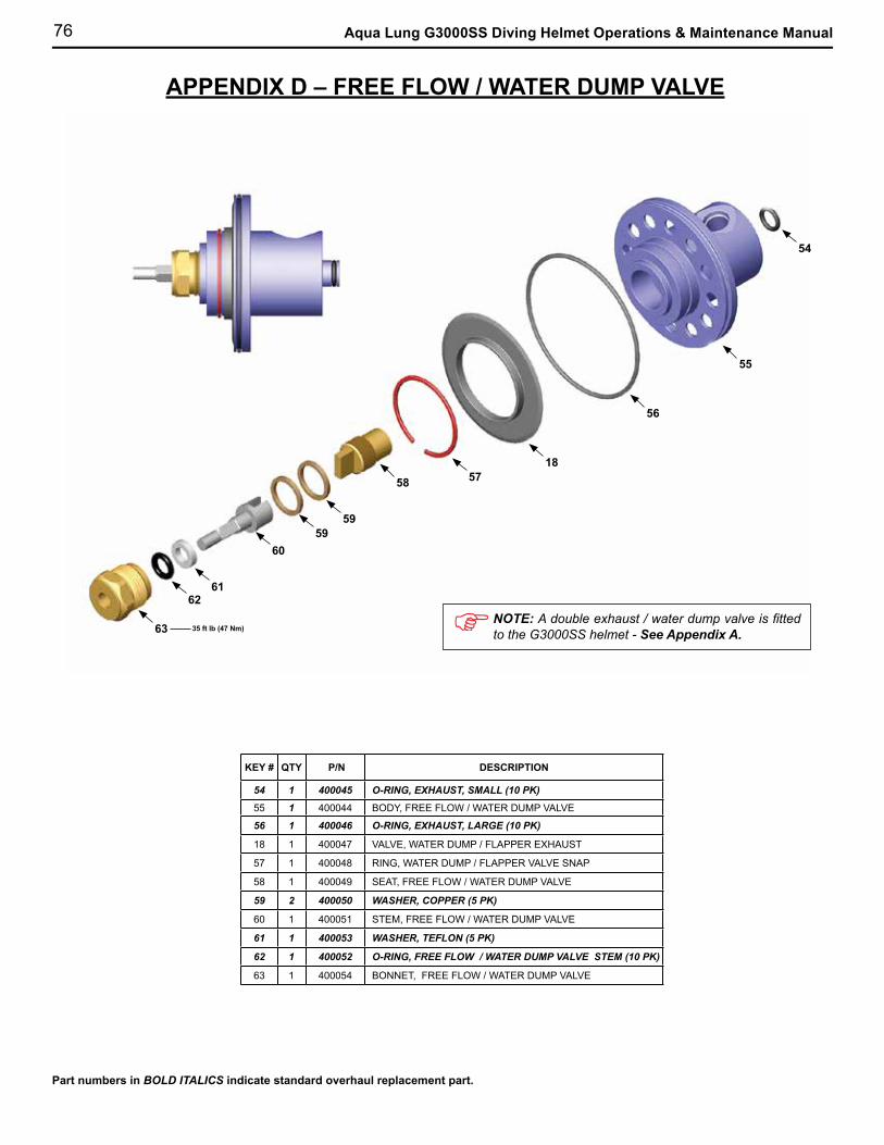
76 Aqua Lung G3000SS Diving Helmet Operations & Maintenance Manual
APPENDIX D – FREE FLOW / WATER DUMP VALVE
KEY # QTY P/N DESCRIPTION
54 1 400045 O-RING, EXHAUST, SMALL (10 PK)
55 1 400044 BODY, FREE FLOW / WATER DUMP VALVE
56 1 400046 O-RING, EXHAUST, LARGE (10 PK)
18 1 400047 VALVE, WATER DUMP / FLAPPER EXHAUST
57 1 400048 RING, WATER DUMP / FLAPPER VALVE SNAP
58 1 400049 SEAT, FREE FLOW / WATER DUMP VALVE
59 2 400050 WASHER, COPPER (5 PK)
60 1 400051 STEM, FREE FLOW / WATER DUMP VALVE
61 1 400053 WASHER, TEFLON (5 PK)
62 1 400052 O-RING, FREE FLOW / WATER DUMP VALVE STEM (10 PK)
63 1 400054 BONNET, FREE FLOW / WATER DUMP VALVE
Part numbers in BOLD ITALICS indicate standard overhaul replacement part.
NOTE: A double exhaust / water dump valve is fitted to the G3000SS helmet - See Appendix A.
54
55
56
185758
5959
60
6162
63 35 ft lb (47 Nm)
77
APPENDIX E – SECOND STAGE REGULATOR
NOTE: Complete service and maintenance instructions for the Apeks GX300 Second Stage Regulator are contained in the separate Apeks document GX300 REGULATOR FOR THE AQUA LUNG G3000SS DIVING HELMET - MAINTENANCE MANUAL.
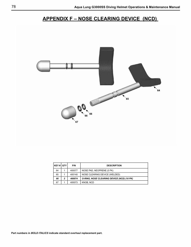
78 Aqua Lung G3000SS Diving Helmet Operations & Maintenance Manual
APPENDIX F – NOSE CLEARING DEVICE (NCD)
Part numbers in BOLD ITALICS indicate standard overhaul replacement part.
64
65
6666
67
KEY # QTY P/N DESCRIPTION
64 1 400077 NOSE PAD, NEOPRENE (5 PK)
65 1 400140 NOSE CLEARING DEVICE (WELDED)
66 2 400074 O-RING, NOSE CLEARING DEVICE (NCD) (10 PK)
67 1 400073 KNOB, NCD
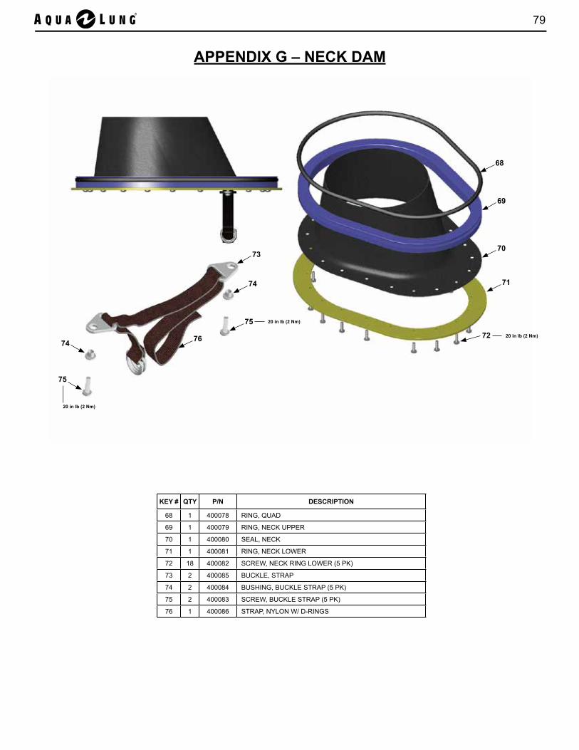
79
APPENDIX G – NECK DAM
KEY # QTY P/N DESCRIPTION
68 1 400078 RING, QUAD
69 1 400079 RING, NECK UPPER
70 1 400080 SEAL, NECK
71 1 400081 RING, NECK LOWER
72 18 400082 SCREW, NECK RING LOWER (5 PK)
73 2 400085 BUCKLE, STRAP
74 2 400084 BUSHING, BUCKLE STRAP (5 PK)
75 2 400083 SCREW, BUCKLE STRAP (5 PK)
76 1 400086 STRAP, NYLON W/ D-RINGS
68
20 in lb (2 Nm)
69
70
71
72
73
74
75
76
20 in lb (2 Nm)
74
75
20 in lb (2 Nm)
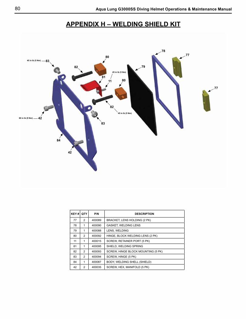
80 Aqua Lung G3000SS Diving Helmet Operations & Maintenance Manual
APPENDIX H – WELDING SHIELD KIT
KEY # QTY P/N DESCRIPTION
77 2 400089 BRACKET, LENS HOLDING (2 PK)
78 1 400090 GASKET, WELDING LENS
79 1 400088 LENS, WELDING
80 2 400092 HINGE, BLOCK WELDING LENS (2 PK)
11 1 400015 SCREW, RETAINER PORT (5 PK)
81 1 400095 SHIELD, WELDING SPRING
82 2 400093 SCREW, HINGE BLOCK MOUNTING (5 PK)
83 2 400094 SCREW, HINGE (5 PK)
84 1 400087 BODY, WELDING SHELL (SHIELD)
42 2 400035 SCREW, HEX, MANIFOLD (5 PK)
77
77
78
79
80
82
80
82
8111
83
8342
42
84
80 in lb (9 Nm)
45 in lb (5 Nm)
45 in lb (5 Nm)
45 in lb (5 Nm)
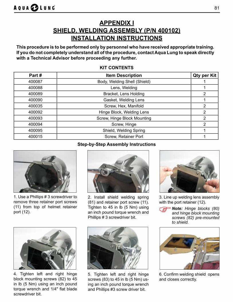
81
APPENDIX ISHIELD, WELDING ASSEMBLY (P/N 400102)
INSTALLATION INSTRUCTIONS This procedure is to be performed only by personnel who have received appropriate training. If you do not completely understand all of the procedure, contact Aqua Lung to speak directly with a Technical Advisor before proceeding any further.
1. Use a Phillips # 3 screwdriver to remove three retainer port screws (11) from top of helmet retainer port (12).
2. Install shield welding spring (81) and retainer port screw (11). Tighten to 45 in lb (5 Nm) using an inch pound torque wrench and Phillips # 3 screwdriver bit.
3. Line up welding lens assembly with the port retainer (12).
4. Tighten left and right hinge block mounting screws (82) to 45 in lb (5 Nm) using an inch pound torque wrench and 1/4" flat blade screwdriver bit.
5. Tighten left and right hinge screws (83) to 45 in lb (5 Nm) us-ing an inch pound torque wrench and Phillips #3 screw driver bit.
6. Confirm welding shield opens and closes correctly.
KIT CONTENTSPart # Item Description Qty per Kit400087 Body, Welding Shell (Shield) 1400088 Lens, Welding 1400089 Bracket, Lens Holding 2400090 Gasket, Welding Lens 1400035 Screw, Hex, Manifold 2400092 Hinge Block, Welding Lens 2400093 Screw, Hinge Block Mounting 2400094 Screw, Hinge 2400095 Shield, Welding Spring 1400015 Screw, Retainer Port 1
Step-by-Step Assembly Instructions
Note: Hinge blocks (80) and hinge block mounting screws (82) pre-mounted to shield.

82 Aqua Lung G3000SS Diving Helmet Operations & Maintenance Manual
APPENDIX JFREE FLOW PLUG INSERT KIT (P/N 400112)
INSTALLATION INSTRUCTIONS
This procedure is to be performed only by personnel who have received appropriate training. If you do not completely understand all of the procedure, contact Aqua Lung to speak directly with a Technical Advisor before proceeding any further.
1. Remove knob (67) from nose clearing device (65).
2. Remove NCD (65) from helmet shell (1).
3. Remove oral-nasal mask (39) from the regulator.
4. Remove microphone (32) from oral-nasal mask (39).
CAUTION: When the helmet is used in free flow mode the free flow valve must be open and properly adjusted at all times throughout the dive in order to maintain constant air flow. The helmet should be fitted with a double exhaust when used for contaminated water diving.
KIT CONTENTS
Part # Item Description Qty per KitN/A Plug, Insert, Free Flow 1
400046 O-ring, Exhaust (Large) 117306 Hook Fastener, 2.0 in Blk, Pressure Sensitive 117308 Loop Fastener, 1.0 in Blk, Pressure Sensitive 1400009 Screw, Exhaust Valve Cover (5 pk) 1400011 Cover, Regulator 1
Step-by-Step Assembly Instructions
NOTE: Refer to the sepa-rate Apeks Technical Man-ual: GX300 REGULATOR FOR THE AQUA LUNG G3000SS DIVING HELMET - MAINTENANCE MANU-AL for guidance on removal of the GX300 regulator.
5. Remove the second stage regulator.

83
6. Remove defogger train (38) from the free flow barrel (34).
7. Remove free flow barrel (34) from the free flow / water dump valve assembly.
8. Lubricate and install o-ring on outside of free flow plug. Place hook and loop strip on barrel.
9. Install free flow plug into helmet shell (1). Ensure hook and loop strip is facing inward.
10. Place regulator cover onto regulator port.
11. Tighten exhaust valve cover screws using an inch pound torque wrench and Phillips #3 screwdriver bit to 45 in lb (5 Nm).
12. Place hook and loop tab on base of microphone (32).
13. Place microphone (32)on free flow plug.
14. Reinstall NCD (65) into the helmet shell (1)..
15. Place NCD knob (67) on NCD (65) to secure in place.
FREE FLOW KIT PLUG INSTALLATION INSTRUCTIONS (continued)
16. Free flow kit installed into helmet.
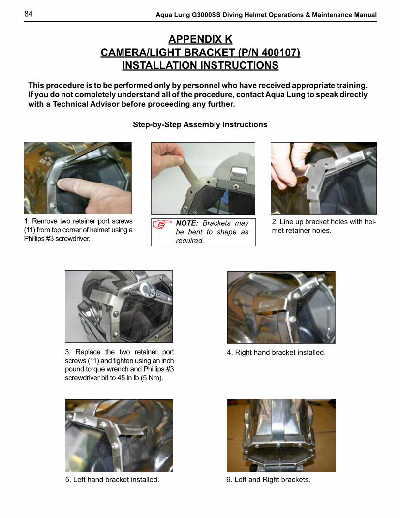
84 Aqua Lung G3000SS Diving Helmet Operations & Maintenance Manual
APPENDIX KCAMERA/LIGHT BRACKET (P/N 400107)
INSTALLATION INSTRUCTIONS
This procedure is to be performed only by personnel who have received appropriate training. If you do not completely understand all of the procedure, contact Aqua Lung to speak directly with a Technical Advisor before proceeding any further.
1. Remove two retainer port screws (11) from top corner of helmet using a Phillips #3 screwdriver.
2. Line up bracket holes with hel-met retainer holes.
3. Replace the two retainer port screws (11) and tighten using an inch pound torque wrench and Phillips #3 screwdriver bit to 45 in lb (5 Nm).
4. Right hand bracket installed.
5. Left hand bracket installed.
Step-by-Step Assembly Instructions
6. Left and Right brackets.
NOTE: Brackets may be bent to shape as required.
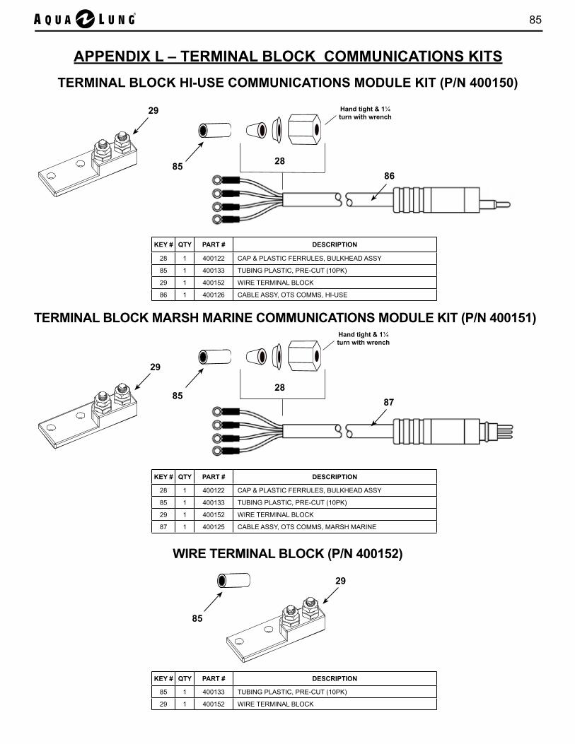
85
TERMINAL BLOCK HI-USE COMMUNICATIONS MODULE KIT (P/N 400150)
TERMINAL BLOCK MARSH MARINE COMMUNICATIONS MODULE KIT (P/N 400151)
29
29
87
85
APPENDIX L – TERMINAL BLOCK COMMUNICATIONS KITS
85
WIRE TERMINAL BLOCK (P/N 400152)
29
KEY # QTY PART # DESCRIPTION
28 1 400122 CAP & PLASTIC FERRULES, BULKHEAD ASSY
85 1 400133 TUBING PLASTIC, PRE-CUT (10PK)
29 1 400152 WIRE TERMINAL BLOCK
86 1 400126 CABLE ASSY, OTS COMMS, HI-USE
KEY # QTY PART # DESCRIPTION
28 1 400122 CAP & PLASTIC FERRULES, BULKHEAD ASSY
85 1 400133 TUBING PLASTIC, PRE-CUT (10PK)
29 1 400152 WIRE TERMINAL BLOCK
87 1 400125 CABLE ASSY, OTS COMMS, MARSH MARINE
85
KEY # QTY PART # DESCRIPTION
85 1 400133 TUBING PLASTIC, PRE-CUT (10PK)
29 1 400152 WIRE TERMINAL BLOCK
28
Hand tight & 1¼ turn with wrench
28
Hand tight & 1¼ turn with wrench
86
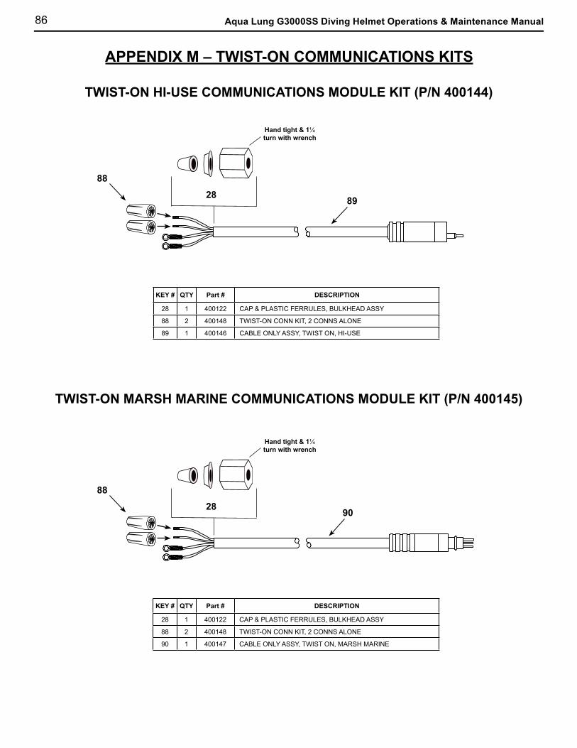
86 Aqua Lung G3000SS Diving Helmet Operations & Maintenance Manual
APPENDIX M – TWIST-ON COMMUNICATIONS KITS
TWIST-ON HI-USE COMMUNICATIONS MODULE KIT (P/N 400144)
KEY # QTY Part # DESCRIPTION
28 1 400122 CAP & PLASTIC FERRULES, BULKHEAD ASSY
88 2 400148 TWIST-ON CONN KIT, 2 CONNS ALONE
89 1 400146 CABLE ONLY ASSY, TWIST ON, HI-USE
KEY # QTY Part # DESCRIPTION
28 1 400122 CAP & PLASTIC FERRULES, BULKHEAD ASSY
88 2 400148 TWIST-ON CONN KIT, 2 CONNS ALONE
90 1 400147 CABLE ONLY ASSY, TWIST ON, MARSH MARINE
TWIST-ON MARSH MARINE COMMUNICATIONS MODULE KIT (P/N 400145)
89
90
88
28
88
28
Hand tight & 1¼ turn with wrench
Hand tight & 1¼ turn with wrench

87
APPENDIX NCOMMUNICATIONS KIT INSTALLATION INSTRUCTIONS
This procedure is to be performed only by personnel who have received appropriate training. If you do not completely understand all of the procedure, contact Aqua Lung to speak directly with a Technical Advisor before proceeding any further.
Installing Terminal Block and Cable Assembly
4-Wire Terminal Block Kit Installation Instructions
1. Use a 3/8" nut driver to remove the communication post hex nuts and communication posts (24) from the helmet shell (1). Remove the old plastic tubing (85) from the communication posts and replace it with new plastic tubing from the communications kit. Re-install the communication posts into the helmet shell. Insert the communication posts through the holes in the terminal block (29) with the "U" shape of the block facing up (Fig. 1). Secure the terminal block to the helmet shell with a 3/8" nut driver and one hex nut per communication post (Fig. 2).
Figure 1 Figure 2
4. Insert the connector cable assembly (86 or 87) through the bulkhead cap (28). Install the ferrules onto the connector cable in the following order: small ferrule (small side towards helmet), then large ferrule (small side towards helmet). Insert the connector cable through the comms bulkhead (26). Tighten the bulkhead cap hand tight, then 1 1/4 turns further with a 11/16" wrench to secure the cable.
5. Connector cable assembly is available with Hi-Use (86) (Fig. 3) or Marsh Marine (87) (Fig. 4) connector.
Figure 4Figure 3
2. Using a 11/16" deep socket and driver, remove the SS cap from the comms bulkhead (26).
3. Use a 15/16" deep socket and foot pound torque wrench, retorque the comms bulkhead (26) to 25 ft lb (34 Nm).
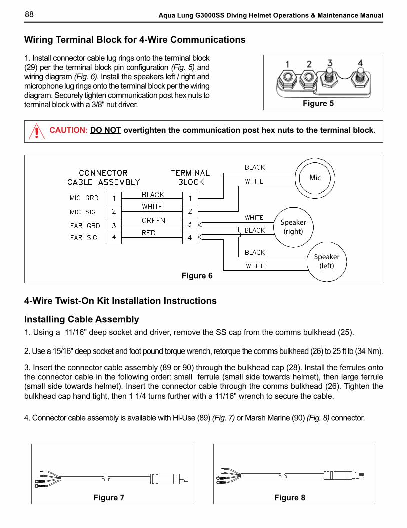
88 Aqua Lung G3000SS Diving Helmet Operations & Maintenance Manual
4. Connector cable assembly is available with Hi-Use (89) (Fig. 7) or Marsh Marine (90) (Fig. 8) connector.
Figure 8Figure 7
1. Install connector cable lug rings onto the terminal block (29) per the terminal block pin configuration (Fig. 5) and wiring diagram (Fig. 6). Install the speakers left / right and microphone lug rings onto the terminal block per the wiring diagram. Securely tighten communication post hex nuts to terminal block with a 3/8" nut driver.
Mic
Speaker(right)
Speaker(left)
Figure 6
Figure 5
CAUTION: DO NOT overtighten the communication post hex nuts to the terminal block.
Installing Cable Assembly
Wiring Terminal Block for 4-Wire Communications
4-Wire Twist-On Kit Installation Instructions
3. Insert the connector cable assembly (89 or 90) through the bulkhead cap (28). Install the ferrules onto the connector cable in the following order: small ferrule (small side towards helmet), then large ferrule (small side towards helmet). Insert the connector cable through the comms bulkhead (26). Tighten the bulkhead cap hand tight, then 1 1/4 turns further with a 11/16" wrench to secure the cable.
1. Using a 11/16" deep socket and driver, remove the SS cap from the comms bulkhead (25).
2. Use a 15/16" deep socket and foot pound torque wrench, retorque the comms bulkhead (26) to 25 ft lb (34 Nm).
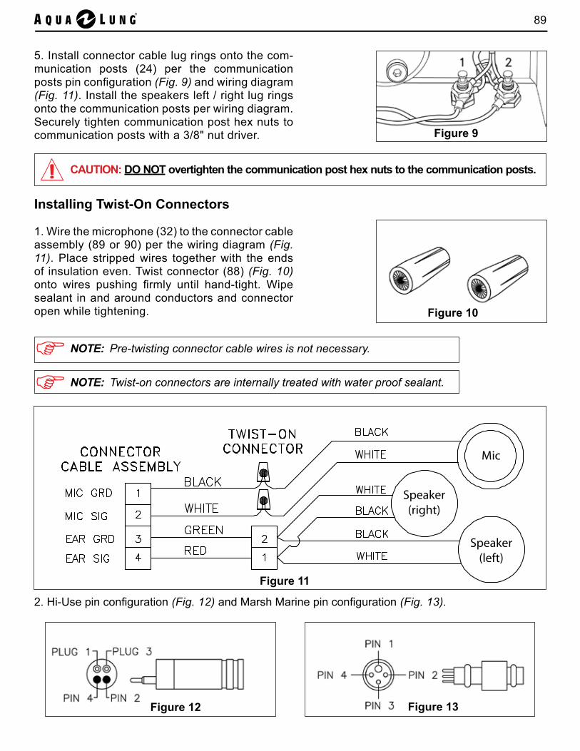
89
5. Install connector cable lug rings onto the com-munication posts (24) per the communication posts pin configuration (Fig. 9) and wiring diagram (Fig. 11). Install the speakers left / right lug rings onto the communication posts per wiring diagram. Securely tighten communication post hex nuts to communication posts with a 3/8" nut driver. Figure 9
Mic
Speaker(right)
Speaker(left)
Figure 11
Installing Twist-On Connectors
1. Wire the microphone (32) to the connector cable assembly (89 or 90) per the wiring diagram (Fig. 11). Place stripped wires together with the ends of insulation even. Twist connector (88) (Fig. 10) onto wires pushing firmly until hand-tight. Wipe sealant in and around conductors and connector open while tightening. Figure 10
CAUTION: DO NOT overtighten the communication post hex nuts to the communication posts.
NOTE: Twist-on connectors are internally treated with water proof sealant.
NOTE: Pre-twisting connector cable wires is not necessary.
Figure 13Figure 12
2. Hi-Use pin configuration (Fig. 12) and Marsh Marine pin configuration (Fig. 13).
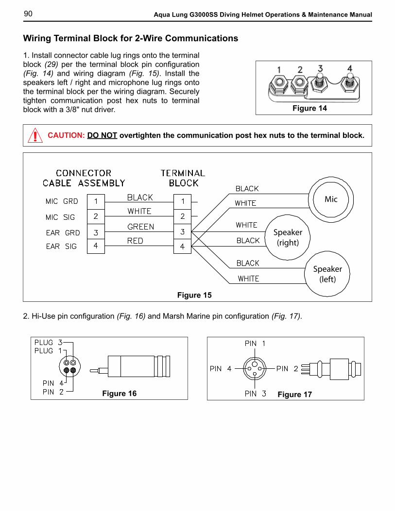
90 Aqua Lung G3000SS Diving Helmet Operations & Maintenance Manual
1. Install connector cable lug rings onto the terminal block (29) per the terminal block pin configuration (Fig. 14) and wiring diagram (Fig. 15). Install the speakers left / right and microphone lug rings onto the terminal block per the wiring diagram. Securely tighten communication post hex nuts to terminal block with a 3/8" nut driver. Figure 14
Mic
Speaker(right)
Speaker(left)
Figure 15
2. Hi-Use pin configuration (Fig. 16) and Marsh Marine pin configuration (Fig. 17).
Mic
Speaker(right)
Speaker(left)
Figure 17
Mic
Speaker(right)
Speaker(left)
Figure 16
CAUTION: DO NOT overtighten the communication post hex nuts to the terminal block.
Wiring Terminal Block for 2-Wire Communications
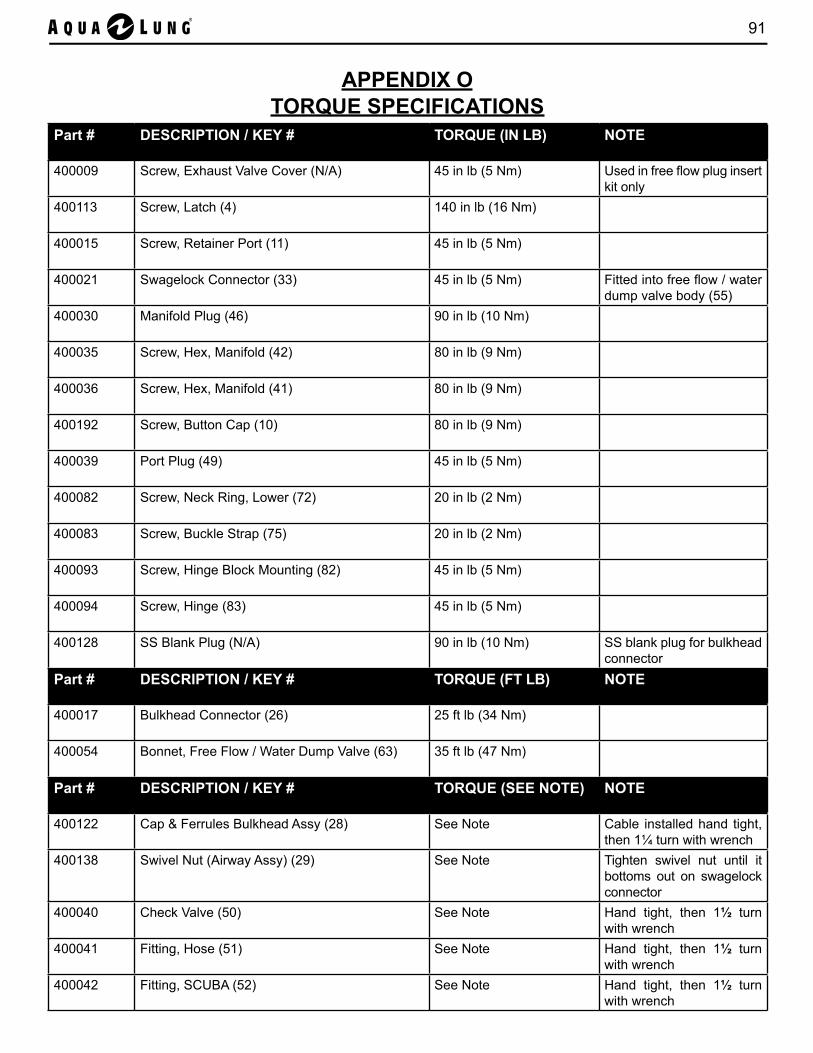
91
Part # DESCRIPTION / KEY # TORQUE (IN LB) NOTE
400009 Screw, Exhaust Valve Cover (N/A) 45 in lb (5 Nm) Used in free flow plug insert kit only
400113 Screw, Latch (4) 140 in lb (16 Nm)
400015 Screw, Retainer Port (11) 45 in lb (5 Nm)
400021 Swagelock Connector (33) 45 in lb (5 Nm) Fitted into free flow / water dump valve body (55)
400030 Manifold Plug (46) 90 in lb (10 Nm)
400035 Screw, Hex, Manifold (42) 80 in lb (9 Nm)
400036 Screw, Hex, Manifold (41) 80 in lb (9 Nm)
400192 Screw, Button Cap (10) 80 in lb (9 Nm)
400039 Port Plug (49) 45 in lb (5 Nm)
400082 Screw, Neck Ring, Lower (72) 20 in lb (2 Nm)
400083 Screw, Buckle Strap (75) 20 in lb (2 Nm)
400093 Screw, Hinge Block Mounting (82) 45 in lb (5 Nm)
400094 Screw, Hinge (83) 45 in lb (5 Nm)
400128 SS Blank Plug (N/A) 90 in lb (10 Nm) SS blank plug for bulkhead connector
Part # DESCRIPTION / KEY # TORQUE (FT LB) NOTE
400017 Bulkhead Connector (26) 25 ft lb (34 Nm)
400054 Bonnet, Free Flow / Water Dump Valve (63) 35 ft lb (47 Nm)
Part # DESCRIPTION / KEY # TORQUE (SEE NOTE) NOTE
400122 Cap & Ferrules Bulkhead Assy (28) See Note Cable installed hand tight, then 1¼ turn with wrench
400138 Swivel Nut (Airway Assy) (29) See Note Tighten swivel nut until it bottoms out on swagelock connector
400040 Check Valve (50) See Note Hand tight, then 1½ turn with wrench
400041 Fitting, Hose (51) See Note Hand tight, then 1½ turn with wrench
400042 Fitting, SCUBA (52) See Note Hand tight, then 1½ turn with wrench
APPENDIX OTORQUE SPECIFICATIONS
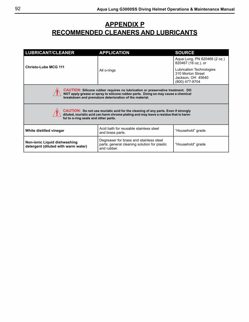
92 Aqua Lung G3000SS Diving Helmet Operations & Maintenance Manual
LUBRICANT/CLEANER APPLICATION SOURCE
Christo-Lube MCG 111All o-rings
Aqua Lung, PN 820466 (2 oz.) 820467 (16 oz.), or
Lubrication Technologies 310 Morton Street Jackson, OH 45640 (800) 477-8704
White distilled vinegar Acid bath for reusable stainless steel and brass parts. “Household” grade
Non-ionic Liquid dishwashing detergent (diluted with warm water)
Degreaser for brass and stainless steel parts; general cleaning solution for plastic and rubber.
“Household” grade
CAUTION: Silicone rubber requires no lubrication or preservative treatment. DO NOT apply grease or spray to silicone rubber parts. Doing so may cause a chemical breakdown and premature deterioration of the material.
CAUTION: Do not use muriatic acid for the cleaning of any parts. Even if strongly diluted, muriatic acid can harm chrome plating and may leave a residue that is harm-ful to o-ring seals and other parts.
APPENDIX PRECOMMENDED CLEANERS AND LUBRICANTS
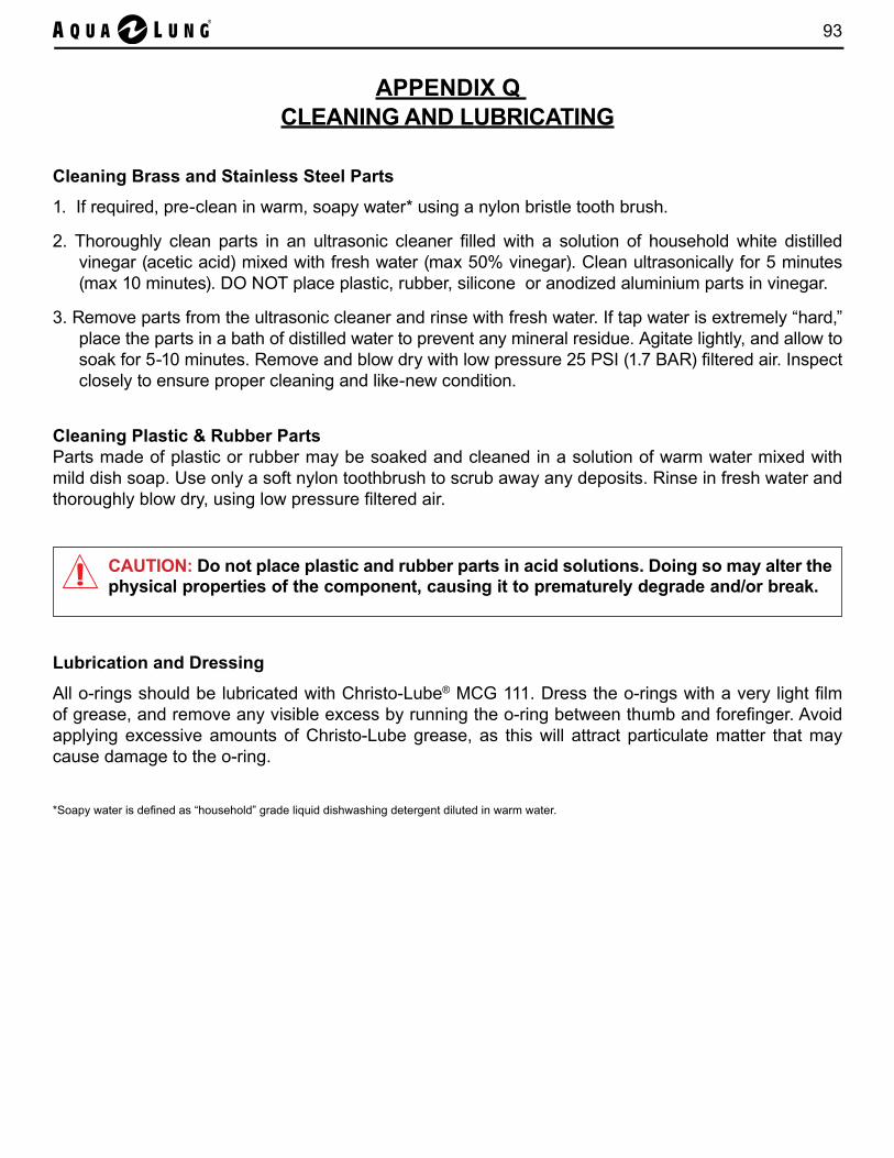
93
APPENDIX Q CLEANING AND LUBRICATING
Cleaning Brass and Stainless Steel Parts
1. If required, pre-clean in warm, soapy water* using a nylon bristle tooth brush.
2. Thoroughly clean parts in an ultrasonic cleaner filled with a solution of household white distilled vinegar (acetic acid) mixed with fresh water (max 50% vinegar). Clean ultrasonically for 5 minutes (max 10 minutes). DO NOT place plastic, rubber, silicone or anodized aluminium parts in vinegar.
3. Remove parts from the ultrasonic cleaner and rinse with fresh water. If tap water is extremely “hard,” place the parts in a bath of distilled water to prevent any mineral residue. Agitate lightly, and allow to soak for 5-10 minutes. Remove and blow dry with low pressure 25 PSI (1.7 BAR) filtered air. Inspect closely to ensure proper cleaning and like-new condition.
Cleaning Plastic & Rubber PartsParts made of plastic or rubber may be soaked and cleaned in a solution of warm water mixed with mild dish soap. Use only a soft nylon toothbrush to scrub away any deposits. Rinse in fresh water and thoroughly blow dry, using low pressure filtered air.
Lubrication and Dressing
All o-rings should be lubricated with Christo-Lube® MCG 111. Dress the o-rings with a very light film of grease, and remove any visible excess by running the o-ring between thumb and forefinger. Avoid applying excessive amounts of Christo-Lube grease, as this will attract particulate matter that may cause damage to the o-ring.
*Soapy water is defined as “household” grade liquid dishwashing detergent diluted in warm water.
CAUTION: Do not place plastic and rubber parts in acid solutions. Doing so may alter the physical properties of the component, causing it to prematurely degrade and/or break.

94 Aqua Lung G3000SS Diving Helmet Operations & Maintenance Manual
APPENDIX R
G3000SS ANNUAL SERVICE KIT (P/N 400180)G3000SS ANNUAL SERVICE KIT W/O REGULATOR (P/N 400183)
The Key # (column D) is provided to assist with correct parts identification and refers to the relevant Exploded Parts Diagram (Appendices A thru F).
NOTE: Refer to APEKS GX300 REGULATOR FOR THE AQUA LUNG G3000SS DIVING HELMET - MAINTENANCE MANUAL for contents of this kit.
A B C D
Part # Item Description Qty per Kit Key #
400004 Nut, Neck Retainer 1 22
400012 O-ring, Face Port 1 14
400022 O-ring, Swagelock Connector & Port Plug 2 35
AP6223 Valve, Inhalation 1 36
400031 O-ring, Manifold Plug 2 25
400034 O-ring, Manifold Connector 2 44
400037 Gasket, Manifold 1 45
400045 O-ring, Exhaust (Small) 1 54
400046 O-ring, Exhaust (Large) 1 56
400050 Washer, Copper 2 59
400052 O-ring, Stem, Free Flow / Water Dump Valve 1 62
400053 Washer, Teflon 1 61
400074 O-ring, Nose Clearing Device (NCD) 2 66
400127 Ferrules (Set of Small & Large) 1 27
AP0300/K GX300 Regulator Service Kit 1 See Note
NOTE: G3000SS Annual Service Kit w/o regulator (P/N 4000183 ) includes all the parts listed in the table above accept the AP0300/K GX300 regulator service kit.

95
APPENDIX SG3000SS FIELD SPARES KIT (P/N 400185)
The Key # (column D) is provided to assist with correct parts identification and refers to the relevant Exploded Parts Diagram (Appendices A thru F).
A B C D
Part # Item Description Qty per Kit Key #
400015 Screw (5 Pack) 12/24-5/8” 1 11
400016 Post, Communication 2 24
400025 Mask, Oral-Nasal 1 39
400028 Liner, Head Medium 1 N/S
400047 Valve, Flapper Exhaust 2 18
400051 Stem, Free Flow Valve 1 60
400077 Pad, Nose Neoprene (5 Pack) 1 64
400078 Ring, Quad 1 68
400080 Seal, Neck 1 70
400086 Chin Strap, Nylon 1 76
400127 Ferrules Nylon (10 pack) 1 27
400129 Speaker, Left 1 40
400130 Speaker, Right 1 30
400131 Microphone 1 32
400183 Kit, Annual Service G3000SS W/O Reg 1 N/S
AP0300/K GX300 Regulator Overhaul Kit 1 N/S
AP0271 Oral Nasal Valve Assembly 1 36 & 37
AP0270 Handwheel Assembly 1 20
NOTES:1. The Kit, G3000SS Helmet Field Spares, is intended to provide commonly used spares (i.e.first needs) to
support diving using the G3000SS Diving Helmet.2. The kit contains items that, based on experience, may require replacement during a 12 to 24 month period of use.3. The contents are based on a recommended quantity of 1 kit per 2 to 3 helmets.4. Annual service kits for the helmet and regulator are included in the main kit. It is recommended that these be
used as a source of ready-use spares for unplanned defect rectification. Separate service kits should be kept untouched for actual annual servicing.
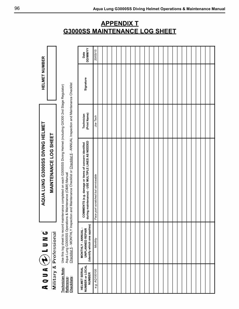
96 Aqua Lung G3000SS Diving Helmet Operations & Maintenance Manual
APPENDIX TG3000SS MAINTENANCE LOG SHEET
Tech
nici
an N
ote:
U
se th
is lo
g sh
eet t
o re
cord
mai
nten
ance
com
plet
ed o
n ea
ch G
3000
SS
Div
ing
Hel
met
(inc
ludi
ng G
X300
2nd
Sta
ge R
egul
ator
)R
efer
ence
: A
qua
Lung
G30
00S
S O
pera
tions
& M
aint
enan
ce (O
&M
) Man
ual
Che
cklis
ts:
Che
cklis
t 5 -
MO
NTH
LY In
spec
tion
and
Mai
nten
ance
Che
cklis
t or C
heck
list 6
- A
NN
UA
L In
spec
tion
and
Mai
nten
ance
Che
cklis
t
HEL
MET
SER
IAL
NU
MB
ER o
r LO
CAL
N
UM
BER
MO
NTH
LY -
ANN
UAL
- U
NPL
ANN
ED R
EPAI
R
(iden
tify
whi
ch o
ne a
pplie
s)
CO
MM
ENTS
(e.g
. dam
age
or it
ems
of c
once
rn id
entif
ed
durin
g m
aint
enan
ce) -
USE
MU
LTIP
LE L
INES
AS
NEE
DED
Tech
nici
an
(P
rint N
ame)
Dat
e
DD
/MM
/YY
e.g.
AQ
1001
00M
onth
ly F
ace
port
scra
tche
d bu
t ser
vice
able
Joe
Tech
20/0
5/15
AQU
A LU
NG
G30
00SS
DIV
ING
HEL
MET
MAI
NTE
NAN
CE
LOG
SH
EET
HEL
MET
NU
MB
ER
Sign
atur
e
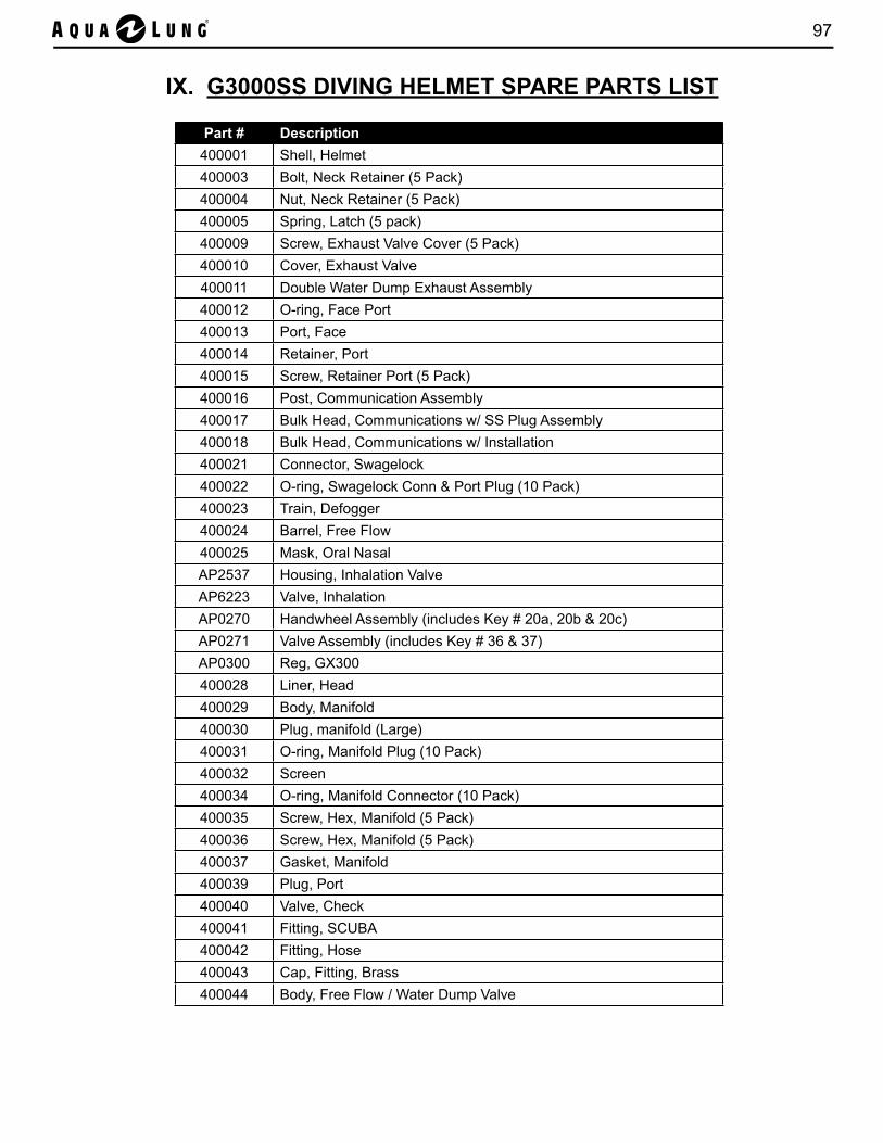
97
IX. G3000SS DIVING HELMET SPARE PARTS LIST
Part # Description400001 Shell, Helmet400003 Bolt, Neck Retainer (5 Pack)400004 Nut, Neck Retainer (5 Pack)400005 Spring, Latch (5 pack)400009 Screw, Exhaust Valve Cover (5 Pack)400010 Cover, Exhaust Valve400011 Double Water Dump Exhaust Assembly400012 O-ring, Face Port400013 Port, Face400014 Retainer, Port400015 Screw, Retainer Port (5 Pack)400016 Post, Communication Assembly400017 Bulk Head, Communications w/ SS Plug Assembly400018 Bulk Head, Communications w/ Installation400021 Connector, Swagelock400022 O-ring, Swagelock Conn & Port Plug (10 Pack)400023 Train, Defogger400024 Barrel, Free Flow400025 Mask, Oral NasalAP2537 Housing, Inhalation ValveAP6223 Valve, Inhalation AP0270 Handwheel Assembly (includes Key # 20a, 20b & 20c)AP0271 Valve Assembly (includes Key # 36 & 37)AP0300 Reg, GX300400028 Liner, Head400029 Body, Manifold400030 Plug, manifold (Large)400031 O-ring, Manifold Plug (10 Pack)400032 Screen400034 O-ring, Manifold Connector (10 Pack)400035 Screw, Hex, Manifold (5 Pack)400036 Screw, Hex, Manifold (5 Pack)400037 Gasket, Manifold400039 Plug, Port400040 Valve, Check400041 Fitting, SCUBA400042 Fitting, Hose400043 Cap, Fitting, Brass400044 Body, Free Flow / Water Dump Valve

98 Aqua Lung G3000SS Diving Helmet Operations & Maintenance Manual
Part # Description400045 O-ring, Exhaust (Small) (10 Pack)400046 O-ring, Exhaust (Large) (10 Pack)400047 Valve, Water Dump / Flapper Exhaust400048 Ring, Water Dump / Flapper Valve Snap400049 Seat, Free Flow / Water Dump Valve400050 Washer, Copper (5 pack)400051 Stem, Free Flow / Water Dump Valve400052 O-ring, Free Flow / Water Dump Valve Stem (10 Pack)400053 Washer, Teflon (5 pack)400054 Valve, Free Flow / Water Dump Bonnet400073 Knob, NCD400074 O-ring, Nose Clearing Device (NCD) (10 Pack)400077 Pad, Nose Neoprene (5 Pack)400078 Ring, Quad400079 Ring, Neck Upper400080 Seal, Neck400081 Ring, Neck Bottom400082 Screw, Neck Ring Lower (5 Pack)400083 Screw, Buckle Strap (5 Pack)400084 Bushing, Buckle Strap (5 Pack)400085 Buckle, Strap400086 Strap, Nylon w/D-Rings400087 Body, Welding Shell (Shield)400088 Lens, Welding400089 Bracket, Lens Holding (2 Pack)400090 Gasket, Welding Lens400092 Hinge Block, Welding Lens (2 Pack)400093 Screw, Hinge Block Mounting (5 pack)400094 Screw, Hinge (5 Pack)400095 Spring, Welding Shield400097 Bushing, Dual Exhaust400098 Seat, Dual Exhaust400099 Ring, Spacer (5 Pack)400102 Shield, Welding Assembly400103 Neck Ring, Assembly400104 Set, Communication400107 Bracket, Light/Camera400109 Locking System, Left400111 Kit, Double Exhaust400112 Kit, Plug Insert Free Flow400113 Screw, Latch 5/16" - 18 x 3/4" Long (5 Pack)400114 Retainer, Neck Ring, Mod 1400120 Washer, Latch Spring (2 Pack)
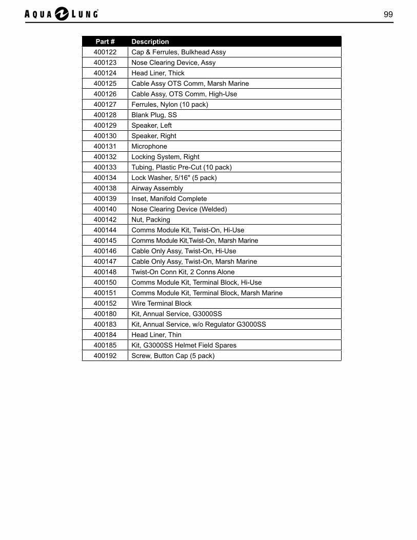
99
Part # Description400122 Cap & Ferrules, Bulkhead Assy400123 Nose Clearing Device, Assy400124 Head Liner, Thick400125 Cable Assy OTS Comm, Marsh Marine400126 Cable Assy, OTS Comm, High-Use400127 Ferrules, Nylon (10 pack)400128 Blank Plug, SS400129 Speaker, Left400130 Speaker, Right400131 Microphone400132 Locking System, Right400133 Tubing, Plastic Pre-Cut (10 pack)400134 Lock Washer, 5/16" (5 pack)400138 Airway Assembly400139 Inset, Manifold Complete400140 Nose Clearing Device (Welded)400142 Nut, Packing400144 Comms Module Kit, Twist-On, Hi-Use400145 Comms Module Kit,Twist-On, Marsh Marine400146 Cable Only Assy, Twist-On, Hi-Use400147 Cable Only Assy, Twist-On, Marsh Marine400148 Twist-On Conn Kit, 2 Conns Alone400150 Comms Module Kit, Terminal Block, Hi-Use400151 Comms Module Kit, Terminal Block, Marsh Marine400152 Wire Terminal Block400180 Kit, Annual Service, G3000SS400183 Kit, Annual Service, w/o Regulator G3000SS400184 Head Liner, Thin400185 Kit, G3000SS Helmet Field Spares400192 Screw, Button Cap (5 pack)
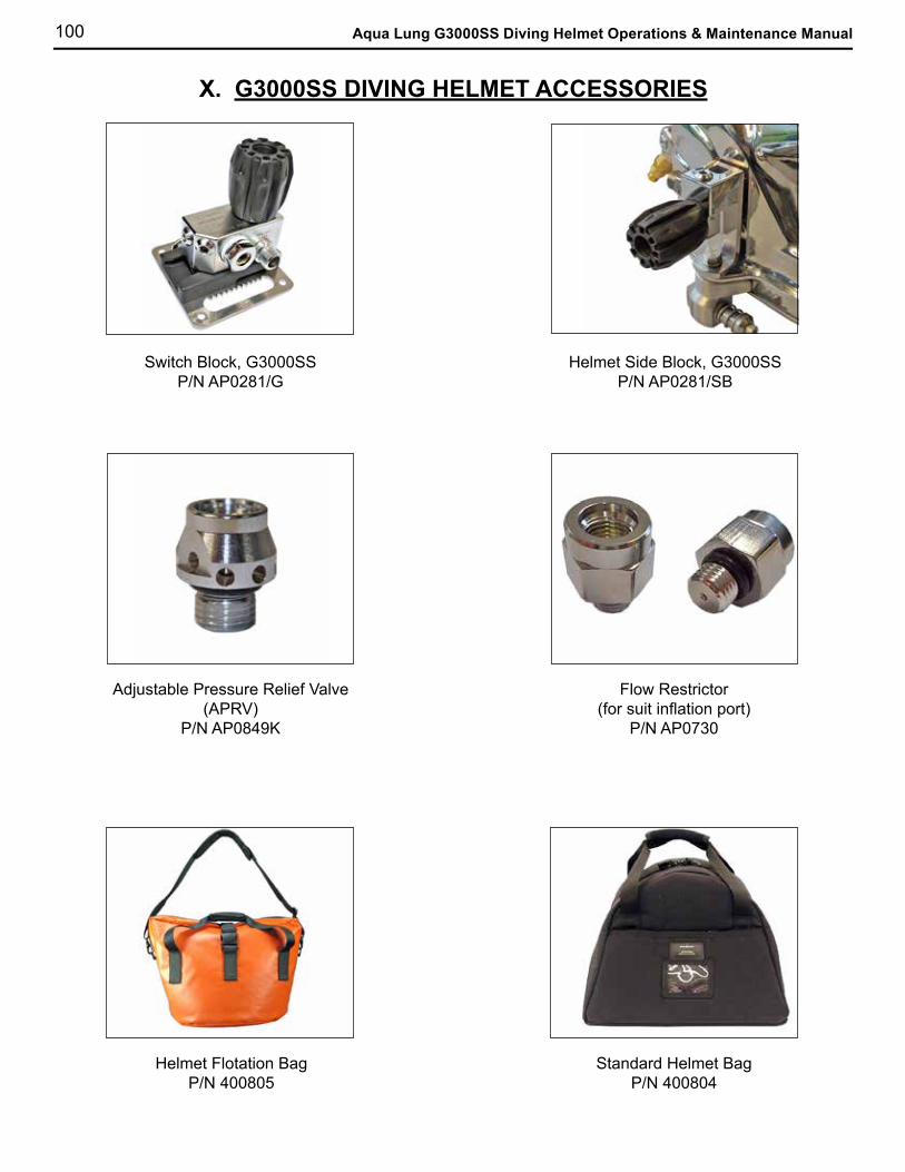
100 Aqua Lung G3000SS Diving Helmet Operations & Maintenance Manual
X. G3000SS DIVING HELMET ACCESSORIES
Switch Block, G3000SS P/N AP0281/G
Helmet Side Block, G3000SS P/N AP0281/SB
Flow Restrictor(for suit inflation port)
P/N AP0730
Adjustable Pressure Relief Valve(APRV)
P/N AP0849K
Helmet Flotation BagP/N 400805
Standard Helmet BagP/N 400804
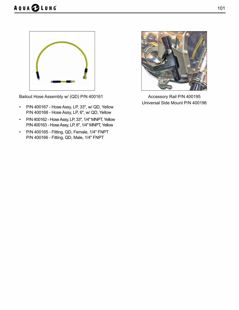
101
Bailout Hose Assembly w/ (QD) P/N 400161
• P/N 400167 - Hose Assy, LP, 33", w/ QD, YellowP/N 400168 - Hose Assy, LP, 6", w/ QD, Yellow
• P/N 400162 - Hose Assy, LP, 33", 1/4" MNPT, YellowP/N 400163 - Hose Assy, LP, 6", 1/4" MNPT, Yellow
• P/N 400165 - Fitting, QD, Female, 1/4" FNPTP/N 400166 - Fitting, QD, Male, 1/4" FNPT
Accessory Rail P/N 400195 Universal Side Mount P/N 400196
©2016 Aqua Lung International
2340 Cousteau Court • Vista, CA 92081Phone (760) 597-5000 • Fax (760) 597-4900www.aqualung.com/militaryandprofessional
www.gorskihat.com
AQUA LUNG G3000SS HELMETOPERATIONS & MAINTENANCE MANUAL