Embed Size (px)
Citation preview
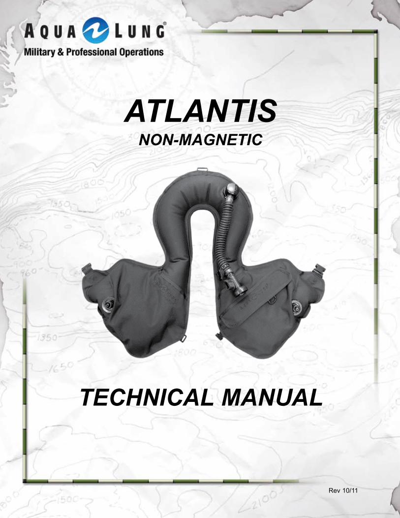
ATLANTISNON-MAGNETIC
TECHNICAL MANUAL
Rev 10/11
A note is used to emphasize important points, tips, and reminders.
A WARNING indicates a procedure or situation that, if not avoided, could result in serious injury or death to the user.
A cAutIoN indicates any situation or technique that could cause damage to the product, and could subsequently result in injury to the user.
coPYRIGHt NotIcE
This manual is copyrighted, all rights reserved. It may not, in whole or in part, be copied, photocopied, reproduced, translated or reduced to any electronic medium or machine-readable form without prior con-sent in writing from Aqua Lung International. It may not be distributed through the internet or computer bulletin board systems without prior consent in writing from Aqua Lung International.
©2011 AquA LuNG AmERIcA. AtLANtIS NoN-mAG tEcHNIcAL mANuAL, PN 762988
Atlantis Bc w/ cylinder Non-mag PN# 762970Atlantis Bc w/o cylinder Non-mag PN# 762980
You can contact a technical Advisor via e-mail at:
Aqua Lung [email protected]
Aqua Lung [email protected]@aqualung.com
Trademark NoticeAqua Lung®, is a registered trademark of Aqua Lung America, Inc.
Warnings, Cautions and Notes:Pay special attention to information provided in warnings, cautions, and notes,
that is accompanied by these symbols:
2 Atlantis Non-mag technical manual
coNtENtSINtRoDuctIoN ......................................................................................... 5GENERAL PREcAutIoNS AND WARNINGS .......................................... 7PRoDuct oVERVIEW .............................................................................. 9SPEcIAL FEAtuRES ................................................................................. 9BC Air Breathing .................................................................................................................. 9
Padded Neck Collar & Pocket ........................................................................................... 10
Cap .................................................................................................................................... 10
AuXILIARY AIR cYLINDER ..................................................................... 10Filling the Auxiliary Cylinder............................................................................................... 10
Attaching the Auxiliary Cylinder ......................................................................................... 12
INFLAtIoN mEtHoDS ............................................................................. 13Using the Oral Inflator........................................................................................................ 13
Using the Auxiliary Air Cylinder.......................................................................................... 13
DEFLAtIoN mEtHoDS ........................................................................... 13Deflating Via the Dual Exhaust Valve ................................................................................ 14
Deflating Via the Oral Inflator ............................................................................................ 14
DoNNING AND ADJuStmENt PRocEDuRES ..................................... 15Donning ............................................................................................................................. 15
Adjusting Strap Length ...................................................................................................... 15
PRE-DIVE INSPEctIoN ........................................................................... 16PoSt DIVE cARE & mAINtENANcE ..................................................... 19AIRWAY NoN-mAG mAINtENANcE PRocEDuRES ............................ 21Airway Non-Mag Disassembly........................................................................................... 21
Oral Inflator Disassembly .................................................................................................. 21
Dual Valve Disassembly .................................................................................................... 22
Oral Inflator Assembly ....................................................................................................... 23
Dual Valve Assembly ......................................................................................................... 25
Airway Non-Mag Assembly................................................................................................ 26
cYLINDER VALVE coNNEctoR mAINtENANcE PRocEDuRES ...... 28Disassembly ...................................................................................................................... 28
Assembly ........................................................................................................................... 29
3
cYLINDER VALVE mAINtENANcE PRocEDuRES .............................. 30Disassembly ...................................................................................................................... 30
Assembly ........................................................................................................................... 32
cylinder Valve testing Procedures ................................................................................ 33
FINAL ASSEmBLY AND tEStING .......................................................... 34Bc PAtcH KIt INStRuctIoNS ............................................................. 36tABLE 1: LISt oF tooLS ...................................................................... 37tABLE 2: toRquE SPEcIFIcAtIoNS ................................................... 39tABLE 3: REcommENDED cLEANERS AND LuBRIcANtS ............... 39PRocEDuRE A: cLEANING AND LuBRIcAtING ................................. 40EXPLoDED PARtS DIAGRAm ................................................................ 41AtLANtIS NoN-mAG comPoNENtS .................................................... 43oVERHAuL PARtS KItS ........................................................................ 44tEcHNIcAL DAtA .................................................................................. 45mAINtENANcE NotES ........................................................................... 46WARRANtY INFoRmAtIoN .................................................................... 47
4 Atlantis Non-mag technical manual
Introduction
This manual provides factory prescribed proce-dures for the correct service and repair of the Aqua Lung product described in this manual. It is not intended to be used as an instructional manual for untrained personnel. The procedures outlined within this manual are to be performed only by personnel who have received Factory Authorized training through an Aqua Lung Service & Repair Seminar. If you do not completely understand all of the procedures outlined in this manual, contact Aqua Lung to speak directly with a Technical Advi-sor before proceeding any further.
It is recommended that the Atlantis should be rinsed in fresh water after use, and it should be stripped down and serviced annually.However, if at all unsure about the correct function-ing of the Atlantis, then it must be officially inspected immediately.
An Official Inspection consists of:
1. Testing instructions see Pre-Dive Inspection.2. Orally inflate the Atlantis. Check that the over pressure relief valve (OPRV)/rapid exhaust valve (REV) are operating correctly, tightened down properly and no leaks are detected.3. A visual inspection of the Atlantis checking that there is no excess wear to the hook/loop material, stitching points are not excessively coming undone, quick release buckles are in good working order and outer bag zipper is moving freely.4. Auxiliary cylinder is full and no leaks are detected. If the Atlantis fails any of the 4 steps, it should be ser-viced by an Aqua Lung trained service technician.
General Guidelines
1. In order to correctly perform the procedures outlined in this manual, it is important to follow each step exactly in the order given. Read over the entire manual to become familiar with all procedures be-fore attempting to disassemble the product in this manual, and to learn which specialty tools and re-placement parts will be required. Keep the manual open beside you for reference while performing each procedure. Do not rely on memory.
2. All service and repair should be carried out in a work area specifically set up and equipped for the task. Adequate lighting, cleanliness, and easy access to all required tools are essential for an ef-ficient repair facility.3. As the valve/inflator is disassembled, reusable components should be segregated and not allowed to intermix with nonreusable parts or parts from other units. Delicate parts, including inlet fittings and crowns which contain critical sealing surfaces, must be protected and isolated from other parts to prevent damage during the cleaning procedure.4. Use only genuine Aqua Lung® parts provided in the overhaul parts kit for this product. DO NOT attempt to substitute an Aqua Lung® part with an-other manufacturer’s, regardless of any similarity in shape or size. 5. Do not attempt to reuse mandatory replacement parts under any circumstances, regardless of the amount of use the product has received since it was manufactured or last serviced.6. When reassembling, it is important to follow ev-ery torque specification prescribed in this manual, using a calibrated torque wrench. Most parts are made of either marine brass or plastic, and can be permanently damaged by excessive stress.
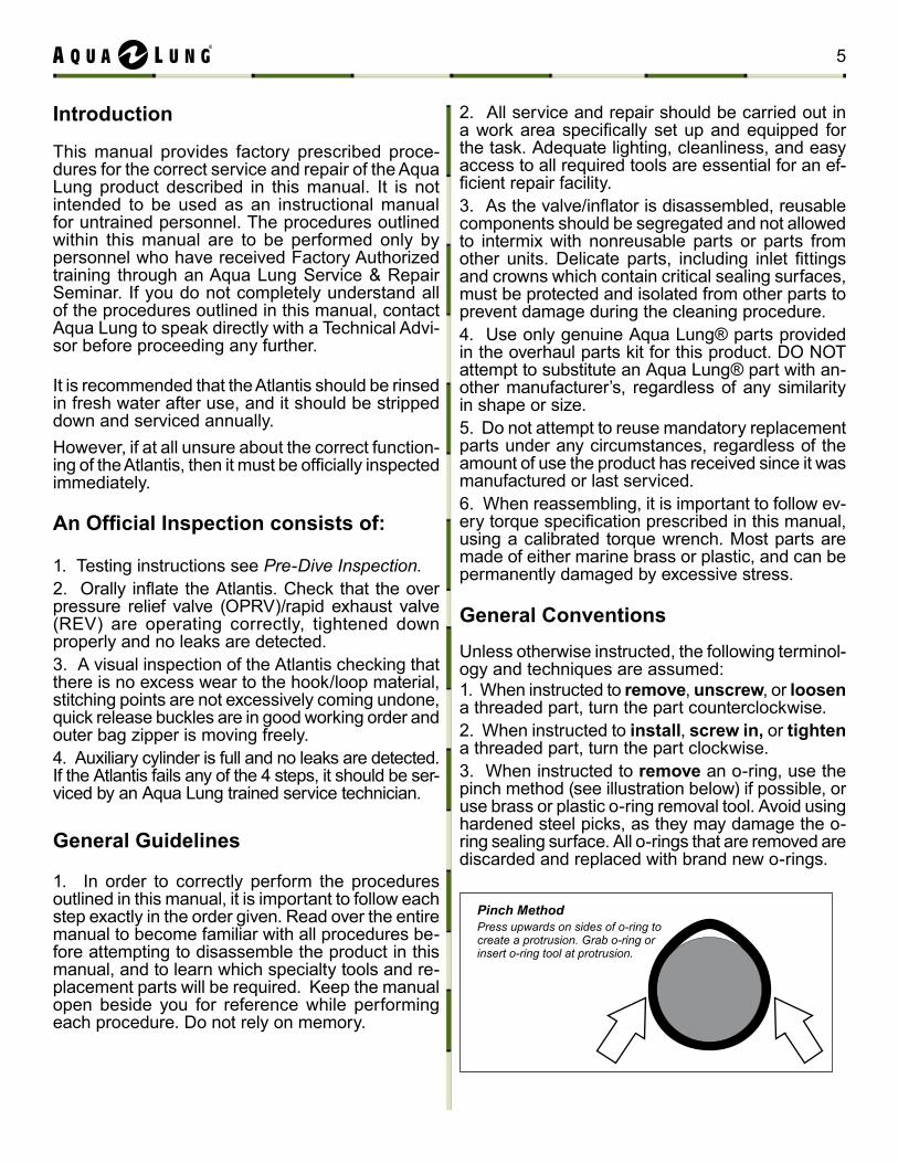
General conventionsUnless otherwise instructed, the following terminol-ogy and techniques are assumed:1. When instructed to remove, unscrew, or loosen a threaded part, turn the part counterclockwise.2. When instructed to install, screw in, or tighten a threaded part, turn the part clockwise.3. When instructed to remove an o-ring, use the pinch method (see illustration below) if possible, or use brass or plastic o-ring removal tool. Avoid using hardened steel picks, as they may damage the o-ring sealing surface. All o-rings that are removed are discarded and replaced with brand new o-rings.
Pinch MethodPress upwards on sides of o-ring to create a protrusion. Grab o-ring or insert o-ring tool at protrusion.
5
cAutIoN: use only a plastic or brass o-ring removal tool (pn 944022) when removing o-rings to prevent damage to the sealing surface. Even a small scratch across an o-ring sealing surface could result in leakage. once an o-ring sealing surface has been damaged, the part must be replaced with new. Do Not use a dental pick or any other steel instrument.
4. The following acronyms are used throughout the manual: mP is Medium Pressure; HP is High Pressure; LP is Low Pressure.5. Numbers in parentheses reference the key numbers on the exploded parts schematics. For example, in the statement, “...remove the o-ring (56) from the valve body...”, the number 56 is the key number to the o-ring.
note: Before performing any disassembly, refer to the exploded parts drawing, which references all mandatory replacement parts. these parts should be replaced with new, and must not be reused un-der any circumstances, regardless of the age of the regulator or how much use it has received since it was last serviced.
6 Atlantis Non-mag technical manual
GENERAL PREcAutIoNS & WARNINGS
WARNING: A buoyancy compensator (Bc) is Not a life jacket! It is not de-signed to provide face-up flotation in all situations; therefore it does not meet U.S. Coast Guard regulations for a life preserver or personal flotation device (PFD). If you become unconscious in the water without a buddy present to immediately give assistance, you may suffer serious injury or death from drowning.
WARNING: Before using the Atlantis, you must have successfully received training and certification in the technique of SCUBA diving from a military or government operated diving school (or any recognized certification agency). Use of this equipment by a person who is not certified by a recognized agency shall render all warranties, express or implied, null and void.
WARNING: Use of SCUBA equipment by uncertified or untrained persons is dangerous and can result in serious injury or death.
WARNING: In an emergency such as an out of air situation or uncontrolled rapid descent, it is important to remove and jettison weight immediately.
WARNING: In the event of an uncontrolled, rapid ascent, it is important to immediately begin venting air from the Atlantis. continue venting air to slow your ascent rate if neutral buoyancy cannot be re-established.
WARNING: Your jacket is not a lift bag. Do Not rely on it to bring heavy ob-jects to the surface. Doing so may permanently damage the jacket and could result in serious injury or death.
WARNING: NEVER lubricate any part of the jacket with any lubricant. Lubri-cation of certain parts and assemblies must only be performed by an Aqua Lung trained service technician.
WARNING: Do not apply any type of aerosol spray to the jacket. Doing so may damage certain plastic components, including important valve connections.
WARNING: Repair, service, or disassembly must not be attempted by persons who are not factory trained and authorized by Aqua Lung. unauthorized service will render the warranty null and void.
7
If you have any questions regarding your Buoyancy Compensator or these instructions, contact
an Aqua Lung technical Representative
Your buoyancy compensator is primarily designed to help you maintain neutral buoy-ancy while in a comfortably balanced, face-down swimming position underwater. It is also designed to provide you with flotation so that you can rest on the surface, but it is not designed to function as a life preserver or personal flotation device (PFD). In or-der to meet u.S. coast Guard regulations, a PFD must be designed so that it automati-cally rights you to a face-up position and holds your head out of the water on the surface.
the design characteristics of a personal flotation device are different from those of a buoyancy compensator. The ability of any flotation device to float you in a face-up po-sition can also be affected by other diving equipment you wear, including a cylinder, weight or exposure suit, and whether it can be inflated before you lose consciousness.
For this reason, it is important always to dive with a buddy and maintain close proximity with them at all times. Do not depend on any flotation device to hold your face above the surface in the event that you are rendered unconscious in the water while diving.
WARNING: Although this manual provides some basic guidelines for certain buoyancy control techniques, it is not a substitute for training from a pro-fessional diving instructor. Failure to weight yourself properly may create a hazardous condition that could lead to serious injury or death. If you are unsure how to weight yourself in order to achieve optimum buoyancy under-water and on the surface, do not dive until you have obtained the necessary instruction from your diving instructor.
8 Atlantis Non-mag technical manual
PRoDuct oVERVIEW
This buoyancy jacket is specifically designed for military use with all types of back or chest worn breath-ing apparatus, including open circuit SCUBA, semi-closed circuit or closed circuit rebreathers.
The Atlantis features two air cylinder attachments that allows you to inflate the vest with com-pressed breathing air. The air cylinders come equipped with a standard connection for use on the jacket. The breathable inflator allows you to breathe from the bladder in an emergency situation. The distribution of the buoyancy chambers provides excellent safety performance, either during buoyant ascent (vertical stability) or at the surface (natural support position with head and shoul-ders out of the water). The bladder is constructed of heavy duty urethane coated 1000 denier black material which resists cuts, tears and abrasion. Two drains with tethered caps on the lower lobe side makes draining fast and easy.It features two flaps with closures on both sides to protect the cylinders. The bag is sewn throughout with high strength nylon. Openings at the bottom allow the cylinder valve to be easily accessible for inflation. A crotch harness with split strap design provides greater comfort while maintaining ease of adjustment. The padded neck collar prevents chaffing and provides a more comfortable fit. A large utility pocket provides extra storage.
The Atlantis is suitable for all types of uses. It must be fitted with two inconel cylinders in order to be completely non-magnetic.
SPEcIAL FEAtuRESBc Air Breathing
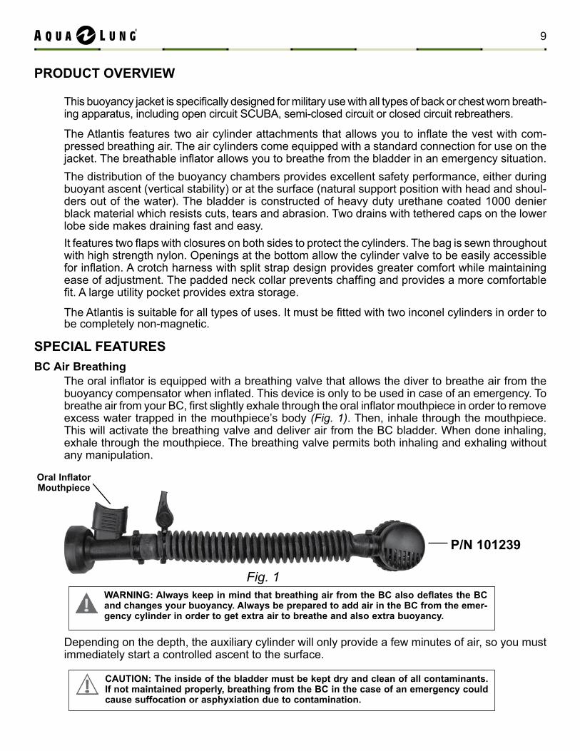
The oral inflator is equipped with a breathing valve that allows the diver to breathe air from the buoyancy compensator when inflated. This device is only to be used in case of an emergency. To breathe air from your BC, first slightly exhale through the oral inflator mouthpiece in order to remove excess water trapped in the mouthpiece’s body (Fig. 1). Then, inhale through the mouthpiece. This will activate the breathing valve and deliver air from the BC bladder. When done inhaling, exhale through the mouthpiece. The breathing valve permits both inhaling and exhaling without any manipulation.
Depending on the depth, the auxiliary cylinder will only provide a few minutes of air, so you must immediately start a controlled ascent to the surface.
P/N 101239
Oral Inflator mouthpiece
Fig. 1
cAutIoN: the inside of the bladder must be kept dry and clean of all contaminants. If not maintained properly, breathing from the Bc in the case of an emergency could cause suffocation or asphyxiation due to contamination.
WARNING: Always keep in mind that breathing air from the BC also deflates the BC and changes your buoyancy. Always be prepared to add air in the Bc from the emer-gency cylinder in order to get extra air to breathe and also extra buoyancy.
9
Filling the Auxiliary cylinder
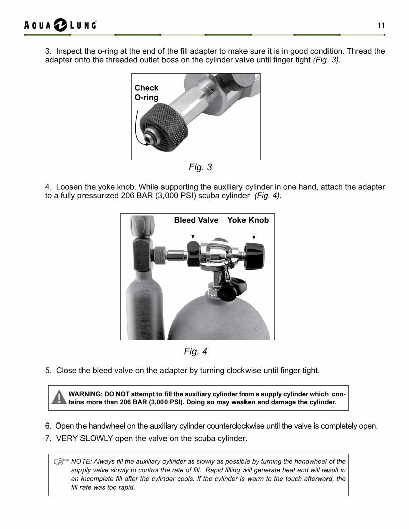
To fill the cylinder, you will need an optional fill adapter: Aqua Lung part number 101215 (Fig. 3).
Padded Neck collar & PocketThe Atlantis features a padded neck collar to prevent chaffing and one large utility pocket located on the left lobe of the BC.
capThe Atlantis is equipped with two caps located on the back of each lobe of the BC. The caps can be removed to rinse the inside of the bladder.
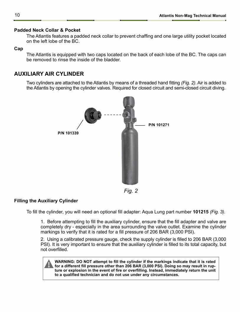
AuXILIARY AIR cYLINDERTwo cylinders are attached to the Atlantis by means of a threaded hand fitting (Fig. 2). Air is added to the Atlantis by opening the cylinder valves. Required for closed circuit and semi-closed circuit diving.
P/N 101339
P/N 101271
Fig. 2
1. Before attempting to fill the auxiliary cylinder, ensure that the fill adapter and valve are completely dry - especially in the area surrounding the valve outlet. Examine the cylinder markings to verify that it is rated for a fill pressure of 206 BAR (3,000 PSI).2. Using a calibrated pressure gauge, check the supply cylinder is filled to 206 BAR (3,000 PSI). It is very important to ensure that the auxiliary cylinder is filled to its total capacity, but not overfilled.
WARNING: DO NOT attempt to fill the cylinder if the markings indicate that it is rated for a different fill pressure other than 206 BAR (3,000 PSI). Doing so may result in rup-ture or explosion in the event of fire or overfilling. Instead, immediately return the unit to a qualified technician and do not use under any circumstances.
10 Atlantis Non-mag technical manual
4. Loosen the yoke knob. While supporting the auxiliary cylinder in one hand, attach the adapter to a fully pressurized 206 BAR (3,000 PSI) scuba cylinder (Fig. 4).
5. Close the bleed valve on the adapter by turning clockwise until finger tight.
6. Open the handwheel on the auxiliary cylinder counterclockwise until the valve is completely open. 7. VERY SLOWLY open the valve on the scuba cylinder.
Fig. 4
Bleed Valve Yoke Knob
3. Inspect the o-ring at the end of the fill adapter to make sure it is in good condition. Thread the adapter onto the threaded outlet boss on the cylinder valve until finger tight (Fig. 3).
WARNING: DO NOT attempt to fill the auxiliary cylinder from a supply cylinder which con-tains more than 206 BAR (3,000 PSI). Doing so may weaken and damage the cylinder.
NOTE: Always fill the auxiliary cylinder as slowly as possible by turning the handwheel of the supply valve slowly to control the rate of fill. Rapid filling will generate heat and will result in an incomplete fill after the cylinder cools. If the cylinder is warm to the touch afterward, the fill rate was too rapid.
Fig. 3
checko-ring
11
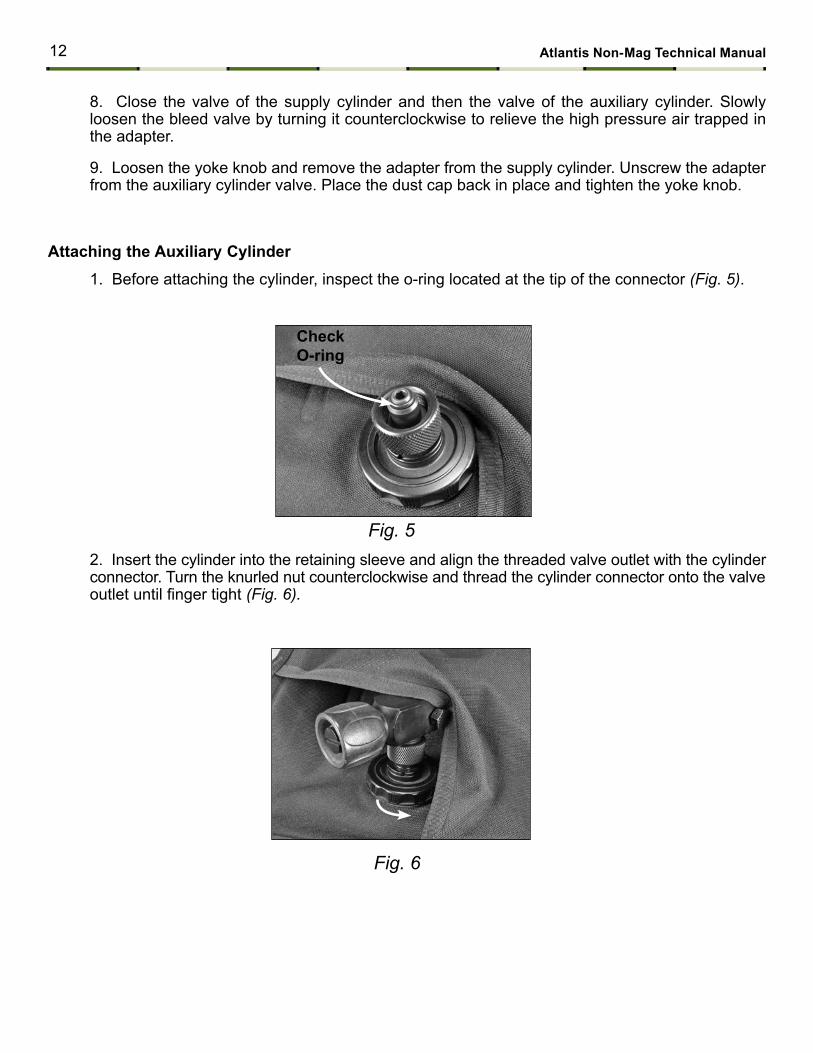
Fig. 5
checko-ring
Fig. 6
Attaching the Auxiliary cylinder
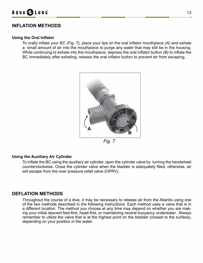
1. Before attaching the cylinder, inspect the o-ring located at the tip of the connector (Fig. 5).
2. Insert the cylinder into the retaining sleeve and align the threaded valve outlet with the cylinder connector. Turn the knurled nut counterclockwise and thread the cylinder connector onto the valve outlet until finger tight (Fig. 6).
8. Close the valve of the supply cylinder and then the valve of the auxiliary cylinder. Slowly loosen the bleed valve by turning it counterclockwise to relieve the high pressure air trapped in the adapter.
9. Loosen the yoke knob and remove the adapter from the supply cylinder. Unscrew the adapter from the auxiliary cylinder valve. Place the dust cap back in place and tighten the yoke knob.
12 Atlantis Non-mag technical manual
INFLAtIoN mEtHoDS
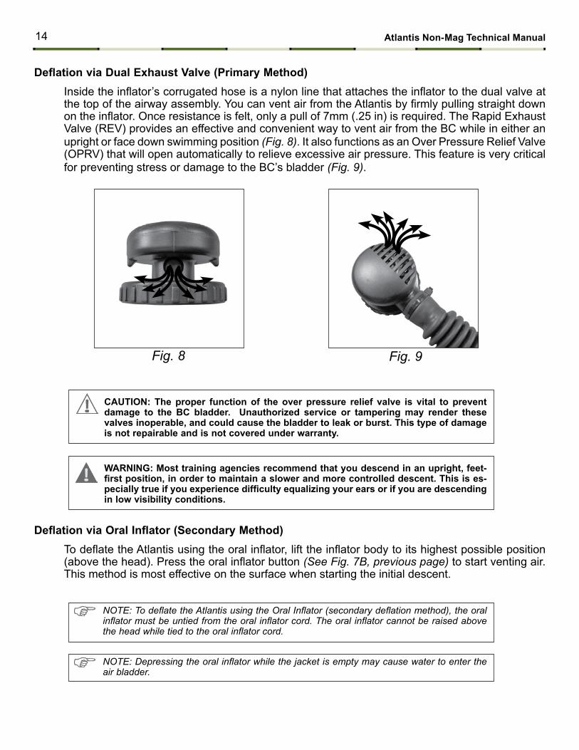
Using the Oral InflatorTo orally inflate your BC (Fig. 7), place your lips on the oral inflator mouthpiece (A) and exhale a small amount of air into the mouthpiece to purge any water that may still be in the housing. While continuing to exhale into the mouthpiece, depress the oral inflator button (B) to inflate the BC immediately after exhaling, release the oral inflator button to prevent air from escaping.
using the Auxiliary Air cylinderTo inflate the BC using the auxiliary air cylinder, open the cylinder valve by turning the handwheel counterclockwise. Close the cylinder valve when the bladder is adequately filled, otherwise, air will escape from the over pressure relief valve (OPRV).
Fig. 7
AB
DEFLAtIoN mEtHoDSThroughout the course of a dive, it may be necessary to release air from the Atlantis using one of the two methods described in the following instructions. Each method uses a valve that is in a different location. The method you choose at any time may depend on whether you are mak-ing your initial descent feet-first, head-first, or maintaining neutral buoyancy underwater. Always remember to utilize the valve that is at the highest point on the bladder (closest to the surface), depending on your position in the water.
13
Deflation via Dual Exhaust Valve (Primary Method)Inside the inflator’s corrugated hose is a nylon line that attaches the inflator to the dual valve at the top of the airway assembly. You can vent air from the Atlantis by firmly pulling straight down on the inflator. Once resistance is felt, only a pull of 7mm (.25 in) is required. The Rapid Exhaust Valve (REV) provides an effective and convenient way to vent air from the BC while in either an upright or face down swimming position (Fig. 8). It also functions as an Over Pressure Relief Valve (OPRV) that will open automatically to relieve excessive air pressure. This feature is very critical for preventing stress or damage to the BC’s bladder (Fig. 9).
NOTE: Depressing the oral inflator while the jacket is empty may cause water to enter the air bladder.
NOTE: To deflate the Atlantis using the Oral Inflator (secondary deflation method), the oral inflator must be untied from the oral inflator cord. The oral inflator cannot be raised above the head while tied to the oral inflator cord.
Fig. 9Fig. 8
Deflation via Oral Inflator (Secondary Method)To deflate the Atlantis using the oral inflator, lift the inflator body to its highest possible position (above the head). Press the oral inflator button (See Fig. 7B, previous page) to start venting air. This method is most effective on the surface when starting the initial descent.
cAutIoN: the proper function of the over pressure relief valve is vital to prevent damage to the Bc bladder. unauthorized service or tampering may render these valves inoperable, and could cause the bladder to leak or burst. this type of damage is not repairable and is not covered under warranty.
WARNING: most training agencies recommend that you descend in an upright, feet-first position, in order to maintain a slower and more controlled descent. This is es-pecially true if you experience difficulty equalizing your ears or if you are descending in low visibility conditions.
14 Atlantis Non-mag technical manual
E
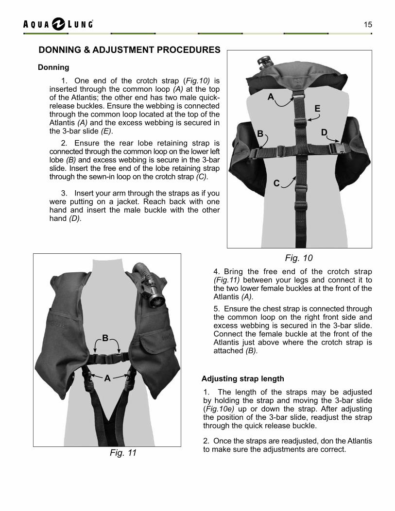
Donning
One end of the crotch strap (1. Fig.10) is inserted through the common loop (A) at the top of the Atlantis; the other end has two male quick-release buckles. Ensure the webbing is connected through the common loop located at the top of the Atlantis (A) and the excess webbing is secured in the 3-bar slide (e).
Ensure the rear lobe retaining strap is 2. connected through the common loop on the lower left lobe (B) and excess webbing is secure in the 3-bar slide. Insert the free end of the lobe retaining strap through the sewn-in loop on the crotch strap (C).
Insert your arm through the straps as if you 3. were putting on a jacket. Reach back with one hand and insert the male buckle with the other hand (D).
Bring the free end of the crotch strap 4. (Fig.11) between your legs and connect it to the two lower female buckles at the front of the Atlantis (A).
Ensure the chest strap is connected through 5. the common loop on the right front side and excess webbing is secured in the 3-bar slide. Connect the female buckle at the front of the Atlantis just above where the crotch strap is attached (B).
DoNNING & ADJuStmENt PRocEDuRES
A
Fig. 10
B
c
D
Fig. 11
A
B
Adjusting strap length
1. The length of the straps may be adjusted by holding the strap and moving the 3-bar slide (Fig.10e) up or down the strap. After adjusting the position of the 3-bar slide, readjust the strap through the quick release buckle.
2. Once the straps are readjusted, don the Atlantis to make sure the adjustments are correct.
15
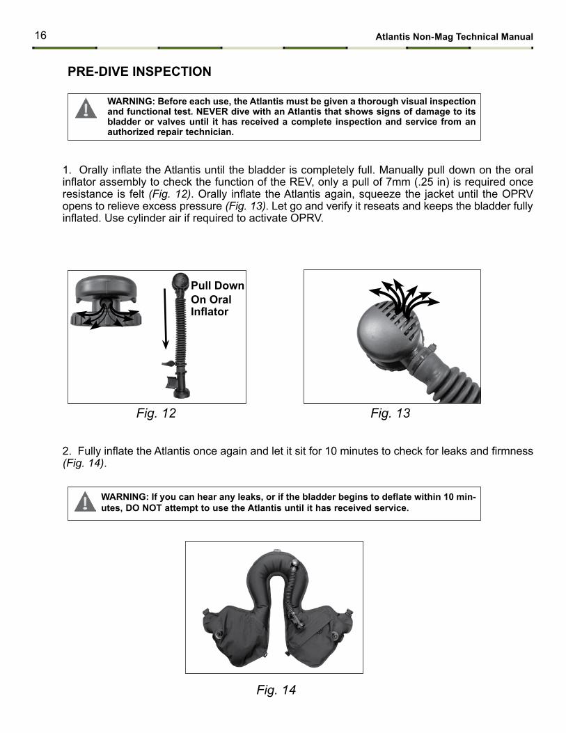
1. Orally inflate the Atlantis until the bladder is completely full. Manually pull down on the oral inflator assembly to check the function of the REV, only a pull of 7mm (.25 in) is required once resistance is felt (Fig. 12). Orally inflate the Atlantis again, squeeze the jacket until the OPRV opens to relieve excess pressure (Fig. 13). Let go and verify it reseats and keeps the bladder fully inflated. Use cylinder air if required to activate OPRV.
2. Fully inflate the Atlantis once again and let it sit for 10 minutes to check for leaks and firmness (Fig. 14).
Fig. 12 Fig. 13
Fig. 14
PRE-DIVE INSPEctIoN
Pull Downon oral Inflator
WARNING: Before each use, the Atlantis must be given a thorough visual inspection and functional test. NEVER dive with an Atlantis that shows signs of damage to its bladder or valves until it has received a complete inspection and service from an authorized repair technician.
WARNING: If you can hear any leaks, or if the bladder begins to deflate within 10 min-utes, Do Not attempt to use the Atlantis until it has received service.
16 Atlantis Non-mag technical manual
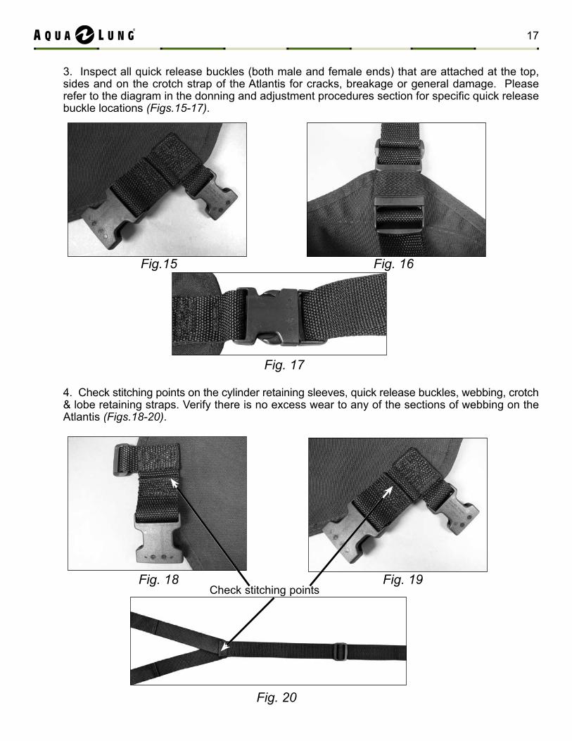
3. Inspect all quick release buckles (both male and female ends) that are attached at the top, sides and on the crotch strap of the Atlantis for cracks, breakage or general damage. Please refer to the diagram in the donning and adjustment procedures section for specific quick release buckle locations (Figs.15-17).
4. Check stitching points on the cylinder retaining sleeves, quick release buckles, webbing, crotch & lobe retaining straps. Verify there is no excess wear to any of the sections of webbing on the Atlantis (Figs.18-20).
Check stitching points
Fig.15 Fig. 16
Fig. 17
Fig. 18 Fig. 19
Fig. 20
17
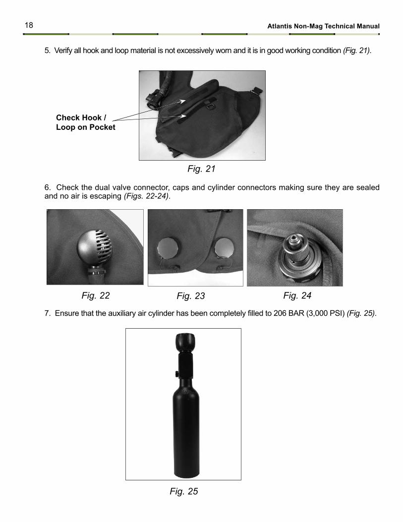
5. Verify all hook and loop material is not excessively worn and it is in good working condition (Fig. 21).
Fig. 21
6. Check the dual valve connector, caps and cylinder connectors making sure they are sealed and no air is escaping (Figs. 22-24).
Fig. 22 Fig. 23
Fig. 25
7. Ensure that the auxiliary air cylinder has been completely filled to 206 BAR (3,000 PSI) (Fig. 25).
check Hook / Loop on Pocket
Fig. 24
18 Atlantis Non-mag technical manual
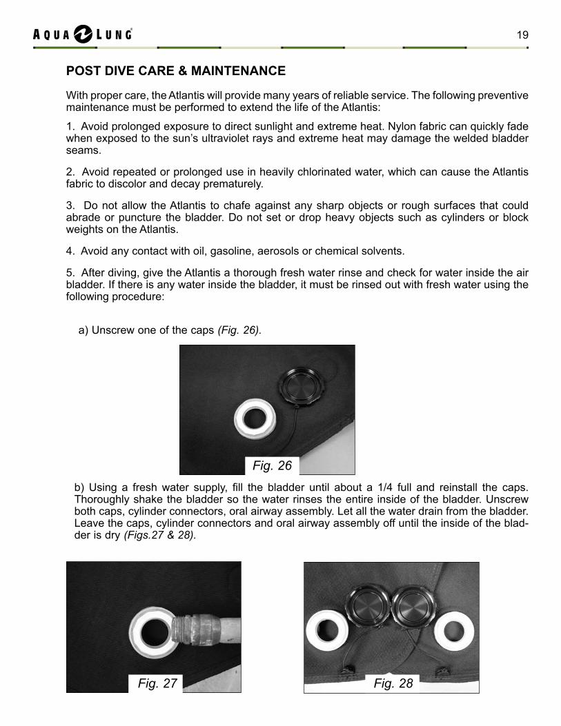
Fig. 26
Fig. 27 Fig. 28
PoSt DIVE cARE & mAINtENANcE
With proper care, the Atlantis will provide many years of reliable service. The following preventive maintenance must be performed to extend the life of the Atlantis:
1. Avoid prolonged exposure to direct sunlight and extreme heat. Nylon fabric can quickly fade when exposed to the sun’s ultraviolet rays and extreme heat may damage the welded bladder seams.
2. Avoid repeated or prolonged use in heavily chlorinated water, which can cause the Atlantis fabric to discolor and decay prematurely.
3. Do not allow the Atlantis to chafe against any sharp objects or rough surfaces that could abrade or puncture the bladder. Do not set or drop heavy objects such as cylinders or block weights on the Atlantis.
4. Avoid any contact with oil, gasoline, aerosols or chemical solvents.
5. After diving, give the Atlantis a thorough fresh water rinse and check for water inside the air bladder. If there is any water inside the bladder, it must be rinsed out with fresh water using the following procedure:
a) Unscrew one of the caps (Fig. 26).
b) Using a fresh water supply, fill the bladder until about a 1/4 full and reinstall the caps. Thoroughly shake the bladder so the water rinses the entire inside of the bladder. Unscrew both caps, cylinder connectors, oral airway assembly. Let all the water drain from the bladder. Leave the caps, cylinder connectors and oral airway assembly off until the inside of the blad-der is dry (Figs.27 & 28).
19
c) Reinstall the caps, cylinder connectors and oral airway assembly. Orally inflate the Atlantis until it is partially inflated. Store the Atlantis partially inflated, away from direct sunlight, in a clean, dry area. Do not store in an enclosed space, such as a car trunk, where temperatures may fall below -18ºC (0ºF) or rise above 49ºC (120ºF).
20 Atlantis Non-mag technical manual
Airway (Non mag) Disassembly
1. Turn the retaining collar and remove the dual valve assembly from the connector. Remove the gasket (12) from the connector.
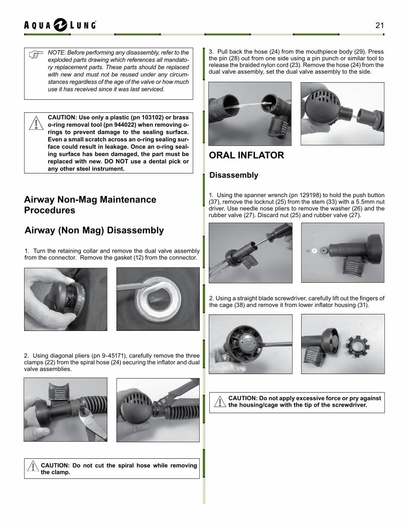
3. Pull back the hose (24) from the mouthpiece body (29). Press the pin (28) out from one side using a pin punch or similar tool to release the braided nylon cord (23). Remove the hose (24) from the dual valve assembly, set the dual valve assembly to the side.
2. Using diagonal pliers (pn 9-45171), carefully remove the three clamps (22) from the spiral hose (24) securing the inflator and dual valve assemblies.
Airway Non-mag maintenance Procedures
note: Before performing any disassembly, refer to the exploded parts drawing which references all mandato-ry replacement parts. these parts should be replaced with new and must not be reused under any circum-stances regardless of the age of the valve or how much use it has received since it was last serviced.
cAutIoN: use only a plastic (pn 103102) or brass o-ring removal tool (pn 944022) when removing o-rings to prevent damage to the sealing surface. Even a small scratch across an o-ring sealing sur-face could result in leakage. once an o-ring seal-ing surface has been damaged, the part must be replaced with new. Do Not use a dental pick or any other steel instrument.
oRAL INFLAtoR
Disassembly
1. Using the spanner wrench (pn 129198) to hold the push button (37), remove the locknut (25) from the stem (33) with a 5.5mm nut driver. Use needle nose pliers to remove the washer (26) and the rubber valve (27). Discard nut (25) and rubber valve (27).
2. Using a straight blade screwdriver, carefully lift out the fingers of the cage (38) and remove it from lower inflator housing (31).
cAutIoN: Do not cut the spiral hose while removing the clamp.
cAutIoN: Do not apply excessive force or pry against the housing/cage with the tip of the screwdriver.
21
Seam
4. Using the spanner wrench (pn 129198), turn the push button (37) counterclockwise to loosen. It may be necessary to secure the stem (33) in a vise or a pair of soft jawed pliers to loosen the push button (37) as a small amount of Loctite 425 or 480 is used to secure the button. Ensure the stem is protected from damage.
5. Remove the push button (37), washer (36) and the inflator diaphragm (35) from the stem (33). Next, remove the plastic valve (34) from the stem (33). It may be necessary to secure the stem in a vise or a pair of soft jawed pliers to remove the plastic valve as a small amount of Loctite 425 or 480 is used on the threads of the stem (33). Once removed, discard the push button (37), washer (36), inflator diaphragm (35) and plastic valve (34).
6. Clean any residual Loctite from the large threads of the stem (33).
This Concludes Disassembly Of The Oral InflatorBefore starting assembly, perform parts clean-ing and lubrication in accordance with Proce-dure A: Cleaning and Lubricating in the back of the manual.
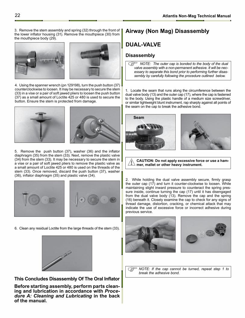
1. Locate the seam that runs along the circumference between the dual valve body (13) and the outer cap (17), where the cap is fastened to the body. Using the plastic handle of a medium size screwdriver, or similar lightweight blunt instrument, rap sharply against all points of the seam on the cap to break the adhesive bond.
Airway (Non mag) Disassembly
DuAL-VALVE
Disassembly
2. While holding the dual valve assembly secure, firmly grasp the outer cap (17) and turn it counter-clockwise to loosen. While maintaining slight inward pressure to counteract the spring pres-sure inside, continue turning the cap (17) until it has disengaged from the dual valve body (13). Remove the cap and the spring (16) beneath it. Closely examine the cap to check for any signs of thread damage, distortion, cracking, or chemical attack that may indicate the use of excessive force or incorrect adhesive during previous service.
3. Remove the stem assembly and spring (32) through the front of the lower inflator housing (31). Remove the mouthpiece (30) from the mouthpiece body (29).
note: the outer cap is bonded to the body of the dual valve assembly with a non-permanent adhesive. It will be nec-essary to separate this bond prior to performing further disas-sembly by carefully following the procedure outlined below.
note: If the cap cannot be turned, repeat step 1 to break the adhesive bond.
cAutIoN: Do not apply excessive force or use a ham-mer, mallet or other heavy instrument.
22 Atlantis Non-mag technical manual
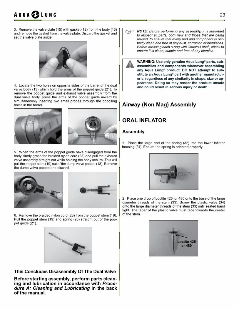
3. Remove the valve plate (15) with gasket (12) from the body (13) and remove the gasket from the valve plate. Discard the gasket and set the valve plate aside.
4. Locate the two holes on opposite sides of the barrel of the dual valve body (13) which hold the arms of the poppet guide (21). To remove the poppet guide and exhaust valve assembly from the dual valve body, press the arms of the poppet guide inward by simultaneously inserting two small probes through the opposing holes in the barrel.
5. When the arms of the poppet guide have disengaged from the body, firmly grasp the braided nylon cord (23) and pull the exhaust valve assembly straight out while holding the body secure. This will pull the poppet stem (19) out of the dump valve poppet (18). Remove the dump valve poppet and discard.
6. Remove the braided nylon cord (23) from the poppet stem (19). Pull the poppet stem (19) and spring (20) straight out of the pop-pet guide (21).
this concludes Disassembly of the Dual ValveBefore starting assembly, perform parts clean-ing and lubrication in accordance with Proce-dure A: Cleaning and Lubricating in the back of the manual.
Loctite 425 or 480
1. Place the large end of the spring (32) into the lower inflator housing (31). Ensure the spring is oriented properly.
2. Place one drop of Loctite 425 or 480 onto the base of the large diameter threads of the stem (33). Screw the plastic valve (34) onto the large diameter threads of the stem (33) until seated hand tight. The taper of the plastic valve must face towards the center of the stem.
oRAL INFLAtoR
Assembly
Airway (Non mag) Assembly
NOTE: Before performing any assembly, it is important to inspect all parts, both new and those that are being reused, to ensure that every part and component is per-fectly clean and free of any dust, corrosion or blemishes. Before dressing each o-ring with Christo-Lube®, check to ensure it is clean, supple and free of any blemish.
WARNING: use only genuine Aqua Lung® parts, sub-assemblies and components whenever assembling any Aqua Lung® product. Do Not attempt to sub-stitute an Aqua Lung® part with another manufactur-er’s, regardless of any similarity in shape, size or ap-pearance. Doing so may render the product unsafe and could result in serious injury or death.
23
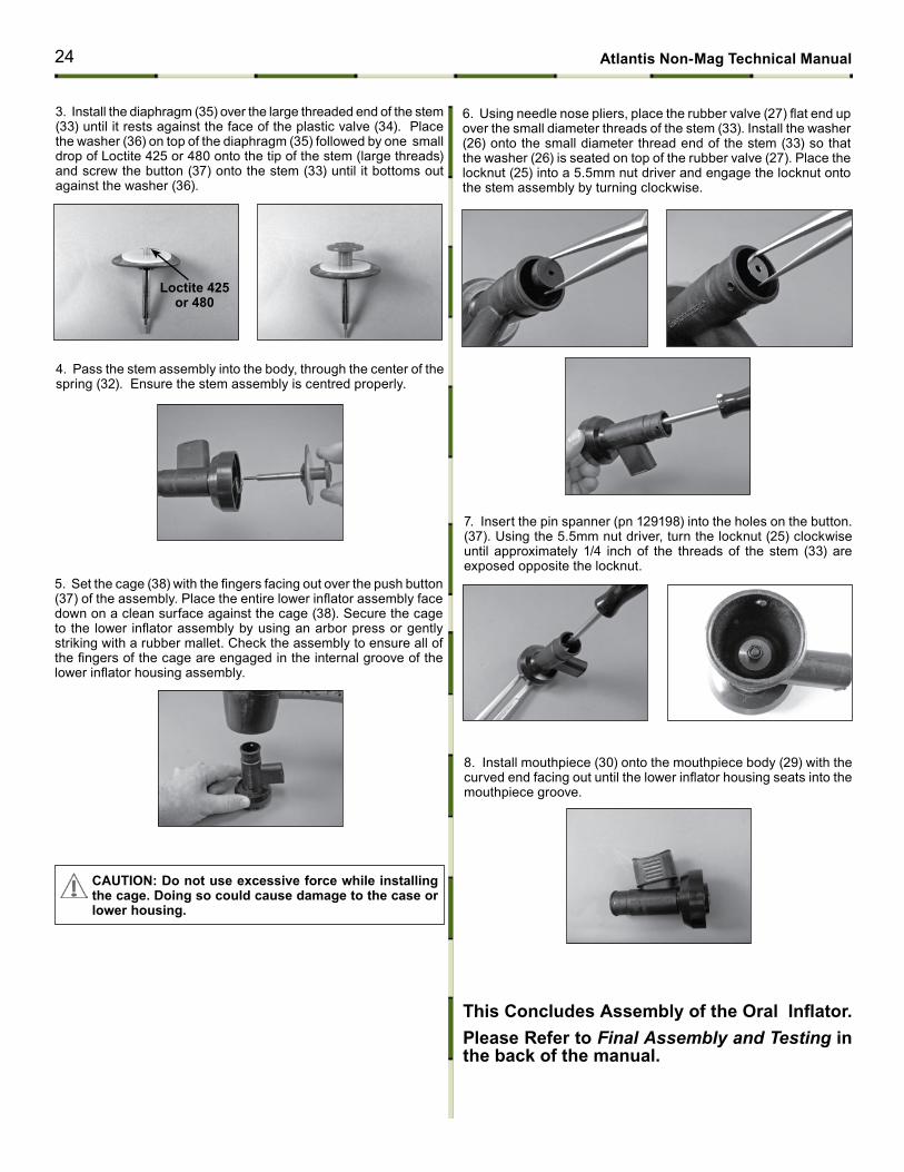
3. Install the diaphragm (35) over the large threaded end of the stem (33) until it rests against the face of the plastic valve (34). Place the washer (36) on top of the diaphragm (35) followed by one small drop of Loctite 425 or 480 onto the tip of the stem (large threads) and screw the button (37) onto the stem (33) until it bottoms out against the washer (36).
4. Pass the stem assembly into the body, through the center of the spring (32). Ensure the stem assembly is centred properly.
5. Set the cage (38) with the fingers facing out over the push button (37) of the assembly. Place the entire lower inflator assembly face down on a clean surface against the cage (38). Secure the cage to the lower inflator assembly by using an arbor press or gently striking with a rubber mallet. Check the assembly to ensure all of the fingers of the cage are engaged in the internal groove of the lower inflator housing assembly.
6. Using needle nose pliers, place the rubber valve (27) flat end up over the small diameter threads of the stem (33). Install the washer (26) onto the small diameter thread end of the stem (33) so that the washer (26) is seated on top of the rubber valve (27). Place the locknut (25) into a 5.5mm nut driver and engage the locknut onto the stem assembly by turning clockwise.
7. Insert the pin spanner (pn 129198) into the holes on the button.(37). Using the 5.5mm nut driver, turn the locknut (25) clockwise until approximately 1/4 inch of the threads of the stem (33) are exposed opposite the locknut.
8. Install mouthpiece (30) onto the mouthpiece body (29) with the curved end facing out until the lower inflator housing seats into the mouthpiece groove.
This Concludes Assembly of the Oral Inflator. Please Refer to Final Assembly and Testing in the back of the manual.
cAutIoN: Do not use excessive force while installing the cage. Doing so could cause damage to the case or lower housing.
Loctite 425 or 480
24 Atlantis Non-mag technical manual
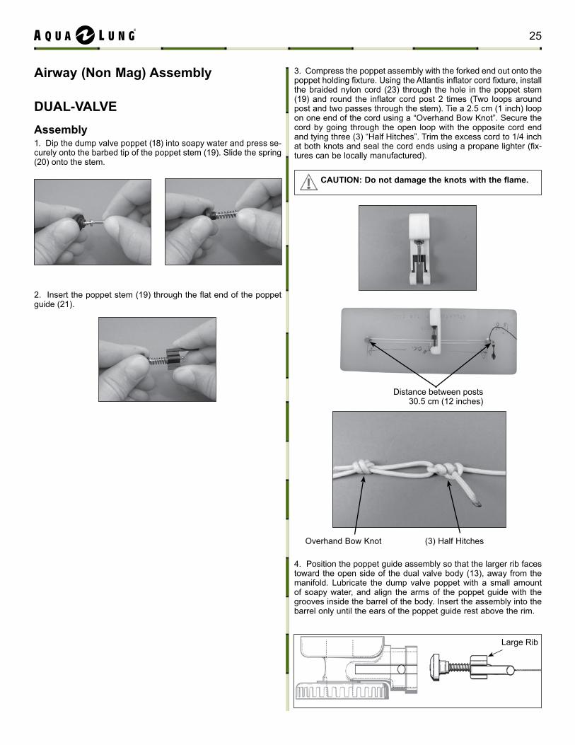
Distance between posts 30.5 cm (12 inches)
(3) Half HitchesOverhand Bow Knot
Large Rib
Airway (Non mag) Assembly
DuAL-VALVEAssembly 1. Dip the dump valve poppet (18) into soapy water and press se-curely onto the barbed tip of the poppet stem (19). Slide the spring (20) onto the stem.
2. Insert the poppet stem (19) through the flat end of the poppet guide (21).
4. Position the poppet guide assembly so that the larger rib faces toward the open side of the dual valve body (13), away from the manifold. Lubricate the dump valve poppet with a small amount of soapy water, and align the arms of the poppet guide with the grooves inside the barrel of the body. Insert the assembly into the barrel only until the ears of the poppet guide rest above the rim.
3. Compress the poppet assembly with the forked end out onto the poppet holding fixture. Using the Atlantis inflator cord fixture, install the braided nylon cord (23) through the hole in the poppet stem (19) and round the inflator cord post 2 times (Two loops around post and two passes through the stem). Tie a 2.5 cm (1 inch) loop on one end of the cord using a “Overhand Bow Knot”. Secure the cord by going through the open loop with the opposite cord end and tying three (3) “Half Hitches”. Trim the excess cord to 1/4 inch at both knots and seal the cord ends using a propane lighter (fix-tures can be locally manufactured).
CAUTION: Do not damage the knots with the flame.
25
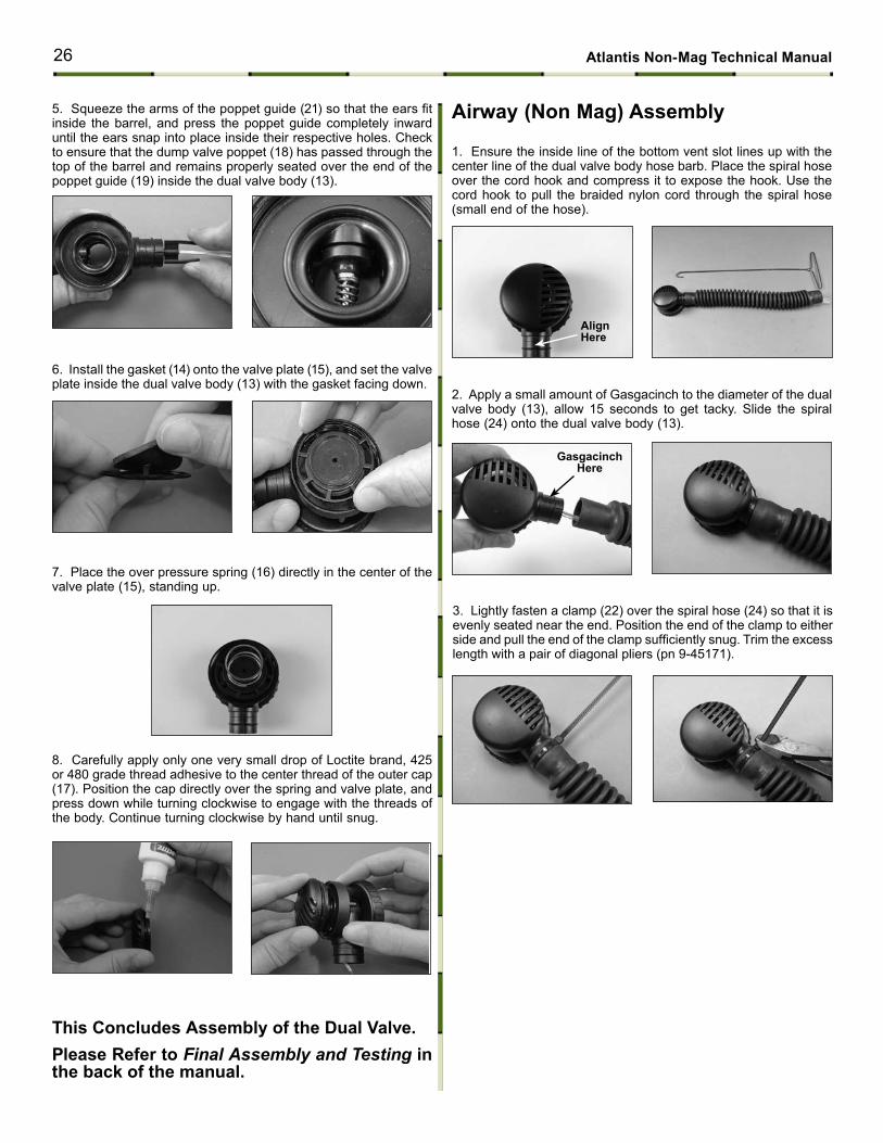
Gasgacinch Here
Align Here
5. Squeeze the arms of the poppet guide (21) so that the ears fit inside the barrel, and press the poppet guide completely inward until the ears snap into place inside their respective holes. Check to ensure that the dump valve poppet (18) has passed through the top of the barrel and remains properly seated over the end of the poppet guide (19) inside the dual valve body (13).
6. Install the gasket (14) onto the valve plate (15), and set the valve plate inside the dual valve body (13) with the gasket facing down.
8. Carefully apply only one very small drop of Loctite brand, 425 or 480 grade thread adhesive to the center thread of the outer cap (17). Position the cap directly over the spring and valve plate, and press down while turning clockwise to engage with the threads of the body. Continue turning clockwise by hand until snug.
7. Place the over pressure spring (16) directly in the center of the valve plate (15), standing up.
3. Lightly fasten a clamp (22) over the spiral hose (24) so that it is evenly seated near the end. Position the end of the clamp to either side and pull the end of the clamp sufficiently snug. Trim the excess length with a pair of diagonal pliers (pn 9-45171).
1. Ensure the inside line of the bottom vent slot lines up with the center line of the dual valve body hose barb. Place the spiral hose over the cord hook and compress it to expose the hook. Use the cord hook to pull the braided nylon cord through the spiral hose (small end of the hose).
2. Apply a small amount of Gasgacinch to the diameter of the dual valve body (13), allow 15 seconds to get tacky. Slide the spiral hose (24) onto the dual valve body (13).
this concludes Assembly of the Dual Valve.Please Refer to Final Assembly and Testing in the back of the manual.
Airway (Non mag) Assembly
26 Atlantis Non-mag technical manual
clamp 1
clamp 2
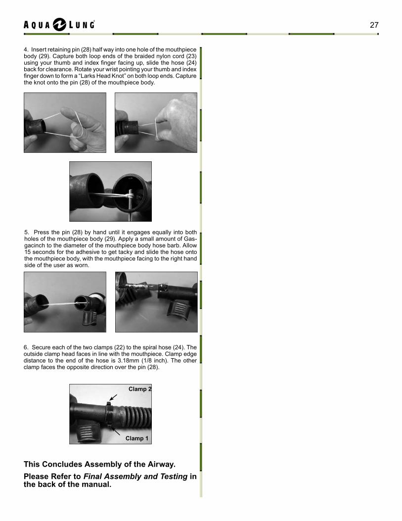
5. Press the pin (28) by hand until it engages equally into both holes of the mouthpiece body (29). Apply a small amount of Gas-gacinch to the diameter of the mouthpiece body hose barb. Allow 15 seconds for the adhesive to get tacky and slide the hose onto the mouthpiece body, with the mouthpiece facing to the right hand side of the user as worn.
6. Secure each of the two clamps (22) to the spiral hose (24). The outside clamp head faces in line with the mouthpiece. Clamp edge distance to the end of the hose is 3.18mm (1/8 inch). The other clamp faces the opposite direction over the pin (28).
4. Insert retaining pin (28) half way into one hole of the mouthpiece body (29). Capture both loop ends of the braided nylon cord (23) using your thumb and index finger facing up, slide the hose (24) back for clearance. Rotate your wrist pointing your thumb and index finger down to form a “Larks Head Knot” on both loop ends. Capture the knot onto the pin (28) of the mouthpiece body.
this concludes Assembly of the Airway.Please Refer to Final Assembly and Testing in the back of the manual.
27
cylinder Valve connector maintenance ProceduresDisassembly
note: Before performing any disassembly, refer to the exploded parts drawing, which references all mandatory replacement parts. these parts should be replaced with new, and must not be reused under any circumstances regardless of the age of the valve or how much use it has received since it was last serviced.
cAutIoN: use only a plastic (pn 103102) or brass o-ring removal tool (pn 944022) when removing o-rings to prevent damage to the sealing surface. Even a small scratch across an o-ring sealing surface could result in leakage. once an o-ring sealing surface has been damaged, the part must be replaced with new. Do Not use a dental pick or any other steel instrument.
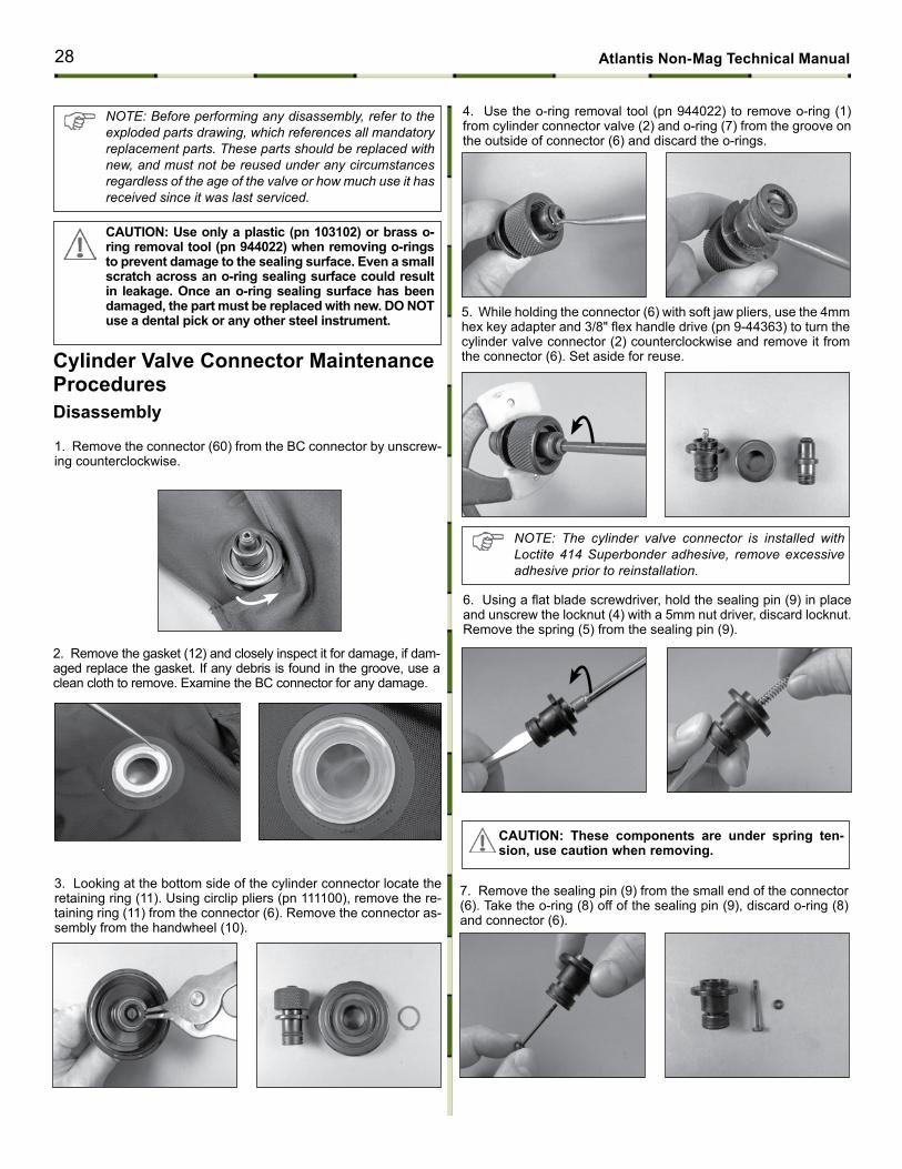
1. Remove the connector (60) from the BC connector by unscrew-ing counterclockwise.
3. Looking at the bottom side of the cylinder connector locate the retaining ring (11). Using circlip pliers (pn 111100), remove the re-taining ring (11) from the connector (6). Remove the connector as-sembly from the handwheel (10).
2. Remove the gasket (12) and closely inspect it for damage, if dam-aged replace the gasket. If any debris is found in the groove, use a clean cloth to remove. Examine the BC connector for any damage.
5. While holding the connector (6) with soft jaw pliers, use the 4mm hex key adapter and 3/8" flex handle drive (pn 9-44363) to turn the cylinder valve connector (2) counterclockwise and remove it from the connector (6). Set aside for reuse.
6. Using a flat blade screwdriver, hold the sealing pin (9) in place and unscrew the locknut (4) with a 5mm nut driver, discard locknut. Remove the spring (5) from the sealing pin (9).
4. Use the o-ring removal tool (pn 944022) to remove o-ring (1) from cylinder connector valve (2) and o-ring (7) from the groove on the outside of connector (6) and discard the o-rings.
note: the cylinder valve connector is installed with Loctite 414 Superbonder adhesive, remove excessive adhesive prior to reinstallation.
7. Remove the sealing pin (9) from the small end of the connector (6). Take the o-ring (8) off of the sealing pin (9), discard o-ring (8) and connector (6).
cAutIoN: these components are under spring ten-sion, use caution when removing.
28 Atlantis Non-mag technical manual
Assembly
NOTE: Before performing any assembly, it is important to inspect all parts, both new and those that are being reused, to ensure that every part and component is per-fectly clean and free of any dust, corrosion, or blemishes. Before dressing each o-ring with Christo-Lube®, check to ensure it is clean, supple, and free of any blemish.
WARNING: use only genuine Aqua Lung® parts, sub-assemblies, and components whenever assem-bling any Aqua Lung® product. Do Not attempt to substitute an Aqua Lung® part with another manu-facturer’s, regardless of any similarity in shape, size or appearance. Doing so may render the product un-safe, and could result in serious injury or death.
cylinder Valve connector maintenance Procedures
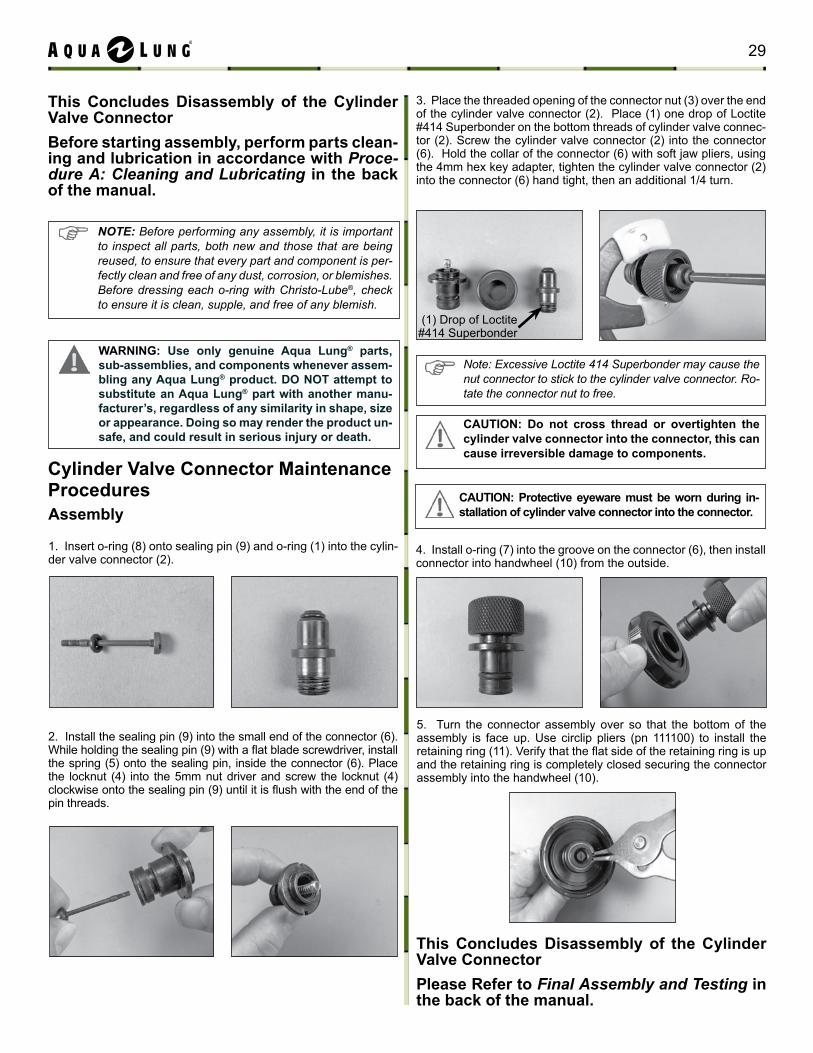
2. Install the sealing pin (9) into the small end of the connector (6). While holding the sealing pin (9) with a flat blade screwdriver, install the spring (5) onto the sealing pin, inside the connector (6). Place the locknut (4) into the 5mm nut driver and screw the locknut (4) clockwise onto the sealing pin (9) until it is flush with the end of the pin threads.
1. Insert o-ring (8) onto sealing pin (9) and o-ring (1) into the cylin-der valve connector (2).
(1) Drop of Loctite#414 Superbonder
3. Place the threaded opening of the connector nut (3) over the end of the cylinder valve connector (2). Place (1) one drop of Loctite #414 Superbonder on the bottom threads of cylinder valve connec-tor (2). Screw the cylinder valve connector (2) into the connector (6). Hold the collar of the connector (6) with soft jaw pliers, using the 4mm hex key adapter, tighten the cylinder valve connector (2) into the connector (6) hand tight, then an additional 1/4 turn.
this concludes Disassembly of the cylinder Valve connectorPlease Refer to Final Assembly and Testing in the back of the manual.
4. Install o-ring (7) into the groove on the connector (6), then install connector into handwheel (10) from the outside.
5. Turn the connector assembly over so that the bottom of the assembly is face up. Use circlip pliers (pn 111100) to install the retaining ring (11). Verify that the flat side of the retaining ring is up and the retaining ring is completely closed securing the connector assembly into the handwheel (10).
cAutIoN: Do not cross thread or overtighten the cylinder valve connector into the connector, this can cause irreversible damage to components.
note: excessive Loctite 414 Superbonder may cause the nut connector to stick to the cylinder valve connector. Ro-tate the connector nut to free.
cAutIoN: Protective eyeware must be worn during in-stallation of cylinder valve connector into the connector.
this concludes Disassembly of the cylinder Valve connectorBefore starting assembly, perform parts clean-ing and lubrication in accordance with Proce-dure A: Cleaning and Lubricating in the back of the manual.
29
note: Before performing any disassembly, refer to the exploded parts drawing, which references all mandatory replacement parts. these parts should be replaced with new, and must not be reused under any circumstances regardless of the age of the valve or how much use it has received since it was last serviced.
cAutIoN: use only a plastic (pn 103102) or brass o-ring removal tool (pn 944022) when removing o-rings to prevent damage to the sealing surface. Even a small scratch across an o-ring sealing surface could result in leakage. once an o-ring sealing surface has been damaged, the part must be replaced with new. Do Not use a dental pick or any other steel instrument.
cylinder Valve Disassembly
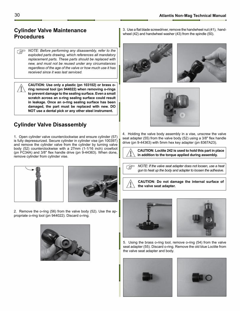
3. Use a flat blade screwdriver, remove the handwheel nut (41), hand-wheel (42) and handwheel washer (43) from the spindle (50).
5. Using the brass o-ring tool, remove o-ring (54) from the valve seat adapter (55). Discard o-ring. Remove the old blue Loctite from the valve seat adapter and body.
note: If the valve seat adapter does not loosen, use a heat gun to heat up the body and adapter to loosen the adhesive.
cAutIoN: Do not damage the internal surface of the valve seat adapter.
cAutIoN: Loctite 242 is used to hold this part in place in addition to the torque applied during assembly.
1. Open cylinder valve counterclockwise and ensure cylinder (57) is fully depressurized. Secure cylinder in cylinder vise (pn 100397) and remove the cylinder valve from the cylinder by turning valve body (52) counterclockwise with a 27mm (1-1/16 inch) crowfoot (pn FC34A) and 3/8" flex handle drive (pn 9-44363). When done, remove cylinder from cylinder vise.
2. Remove the o-ring (56) from the valve body (52). Use the ap-propriate o-ring tool (pn 944022). Discard o-ring.
4. Holding the valve body assembly in a vise, unscrew the valve seat adapter (55) from the valve body (52) using a 3/8" flex handle drive (pn 9-44363) with 5mm hex key adapter (pn 8367A23).
cylinder Valve maintenance Procedures
30 Atlantis Non-mag technical manual
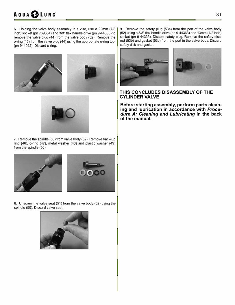
8. Unscrew the valve seat (51) from the valve body (52) using the spindle (50). Discard valve seat.
7. Remove the spindle (50) from valve body (52). Remove back-up ring (46), o-ring (47), metal washer (48) and plastic washer (49) from the spindle (50).
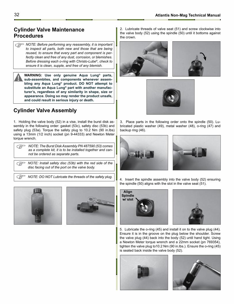
9. Remove the safety plug (53a) from the port of the valve body (52) using a 3/8" flex handle drive (pn 9-44363) and 13mm (1/2 inch) socket (pn 9-44333). Discard safety plug. Remove the safety disc, red (53b) and gasket (53c) from the port in the valve body. Discard safety disk and gasket.
tHIS coNcLuDES DISASSEmBLY oF tHE cYLINDER VALVEBefore starting assembly, perform parts clean-ing and lubrication in accordance with Proce-dure A: Cleaning and Lubricating in the back of the manual.
6. Holding the valve body assembly in a vise, use a 22mm (7/8 inch) socket (pn 769354) and 3/8" flex handle drive (pn 9-44363) to remove the valve plug (44) from the valve body (52). Remove the o-ring (45) from the valve plug (44) using the appropriate o-ring tool (pn 944022). Discard o-ring.
31
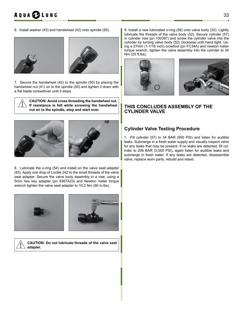
2. Lubricate threads of valve seat (51) and screw clockwise into the valve body (52) using the spindle (50) until it bottoms against the crown.
3. Place parts in the following order onto the spindle (50). Lu-bricated plastic washer (49), metal washer (48), o-ring (47) and backup ring (46).
4. Insert the spindle assembly into the valve body (52) ensuring the spindle (50) aligns with the slot in the valve seat (51).
AlignSpindle w/ slot
5. Lubricate the o-ring (45) and install it on to the valve plug (44). Ensure it is in the groove on the plug below the shoulder. Screw the valve plug (44) back into the body (52) until hand tight. Using a Newton Meter torque wrench and a 22mm socket (pn 769354), tighten the valve plug to10.2 Nm (90 in.lbs.). Ensure the o-ring (45) is seated back inside the valve body (52).
note: Before performing any reassembly, it is important to inspect all parts, both new and those that are being reused, to ensure that every part and component is per-fectly clean and free of any dust, corrosion, or blemishes. Before dressing each o-ring with Christo-Lube®, check to ensure it is clean, supple, and free of any blemish.
WARNING: use only genuine Aqua Lung® parts, sub-assemblies, and components whenever assem-bling any Aqua Lung® product. Do Not attempt to substitute an Aqua Lung® part with another manufac-turer’s, regardless of any similarity in shape, size or appearance. Doing so may render the product unsafe, and could result in serious injury or death.
1. Holding the valve body (52) in a vise, install the burst disk as-sembly in the following order: gasket (53c), safety disc (53b) and safety plug (53a). Torque the safety plug to 10.2 Nm (90 in.lbs) using a 13mm (1/2 inch) socket (pn 9-44333) and Newton Meter torque wrench.
note: The Burst Disk Assembly PN 487590 (53) comes as a complete kit, it is to be installed together and can-not be ordered as separate parts.
note: Install safety disc (53b) with the red side of the disc facing out of the port on the valve body.
note: Do not Lubricate the threads of the safety plug.
cylinder Valve Assembly
cylinder Valve maintenance Procedures
32 Atlantis Non-mag technical manual
tHIS coNcLuDES ASSEmBLY oF tHE cYLINDER VALVE
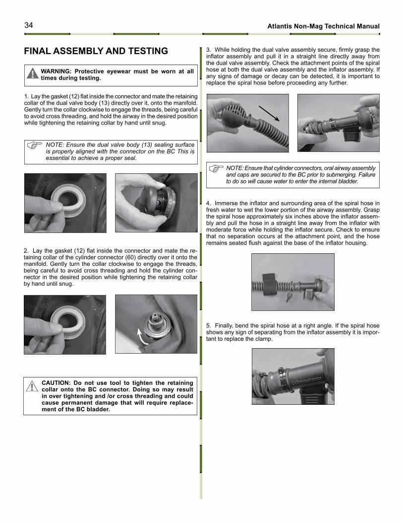
9. Install a new lubricated o-ring (56) onto valve body (52). Lightly lubricate the threads of the valve body (52). Secure cylinder (57) in cylinder vise (pn 100397) and screw the cylinder valve into the cylinder by turning valve body (52) clockwise until hand tight. Us-ing a 27mm (1-1/16 inch) crowfoot (pn FC34A) and newton meter torque wrench, tighten the valve assembly into the cylinder to 34 Nm (25 ft.lbs).
6. Install washer (43) and handwheel (42) onto spindle (50).
7. Secure the handwheel (42) to the spindle (50) by placing the handwheel nut (41) on to the spindle (50) and tighten it down with a flat blade screwdriver until it stops.
cAutIoN: Avoid cross threading the handwheel nut. If resistance is felt while screwing the handwheel nut on to the spindle, stop and start over.
8. Lubricate the o-ring (54) and install on the valve seat adapter (55). Apply one drop of Loctite 242 to the small threads of the valve seat adapter. Secure the valve body assembly in a vise, using a 5mm hex key adapter (pn 8367A23) and Newton meter torque wrench tighten the valve seat adapter to 10.2 Nm (90 in.lbs).
1. Fill cylinder (57) to 34 BAR (500 PSI) and listen for audible leaks. Submerge in a fresh water supply and visually inspect valve for any leaks that may be present. If no leaks are detected, fill cyl-inder to 206 BAR (3,000 PSI), again listen for audible leaks and submerge in fresh water. If any leaks are detected, disassemble valve, replace worn parts, rebuild and retest.
cylinder Valve testing Procedure
cAutIoN: Do not lubricate threads of the valve seat adapter.
33
3. While holding the dual valve assembly secure, firmly grasp the inflator assembly and pull it in a straight line directly away from the dual valve assembly. Check the attachment points of the spiral hose at both the dual valve assembly and the inflator assembly. If any signs of damage or decay can be detected, it is important to replace the spiral hose before proceeding any further.
FINAL ASSEmBLY AND tEStING
1. Lay the gasket (12) flat inside the connector and mate the retaining collar of the dual valve body (13) directly over it, onto the manifold. Gently turn the collar clockwise to engage the threads, being careful to avoid cross threading, and hold the airway in the desired position while tightening the retaining collar by hand until snug.
cAutIoN: Do not use tool to tighten the retaining collar onto the Bc connector. Doing so may result in over tightening and /or cross threading and could cause permanent damage that will require replace-ment of the Bc bladder.
note: ensure that cylinder connectors, oral airway assembly and caps are secured to the BC prior to submerging. Failure to do so will cause water to enter the internal bladder.
WARNING: Protective eyewear must be worn at all times during testing.
note: ensure the dual valve body (13) sealing surface is properly aligned with the connector on the BC this is essential to achieve a proper seal.
5. Finally, bend the spiral hose at a right angle. If the spiral hose shows any sign of separating from the inflator assembly it is impor-tant to replace the clamp.
4. Immerse the inflator and surrounding area of the spiral hose in fresh water to wet the lower portion of the airway assembly. Grasp the spiral hose approximately six inches above the inflator assem-bly and pull the hose in a straight line away from the inflator with moderate force while holding the inflator secure. Check to ensure that no separation occurs at the attachment point, and the hose remains seated flush against the base of the inflator housing.
2. Lay the gasket (12) flat inside the connector and mate the re-taining collar of the cylinder connector (60) directly over it onto the manifold. Gently turn the collar clockwise to engage the threads, being careful to avoid cross threading and hold the cylinder con-nector in the desired position while tightening the retaining collar by hand until snug.
34 Atlantis Non-mag technical manual
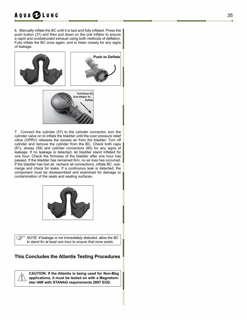
6. Manually inflate the BC until it is taut and fully inflated. Press the push button (37) and then pull down on the oral inflator to ensure a rapid and unobstructed exhaust using both methods of deflation. Fully inflate the BC once again, and to listen closely for any signs of leakage.
Push to Deflate
Pull Down on Oral Inflator To
Deflate
this concludes the Atlantis testing Procedures
cAutIoN: If the Atlantis is being used for Non-mag applications, it must be tested on with a magnetom-eter IAW with StANAG requirements 2897 EoD.
NOTE: If leakage is not immediately detected, allow the BC to stand for at least one hour to ensure that none exists.
7. Connect the cylinder (57) to the cylinder connector, turn the cylinder valve on to inflate the bladder until the over pressure relief valve (OPRV) releases the excess air from the bladder. Turn off cylinder and remove the cylinder from the BC. Check both caps (61), airway (59) and cylinder connectors (60) for any signs of leakage. If no leakage is detected, let bladder stand inflated for one hour. Check the firmness of the bladder after one hour has passed. If the bladder has remained firm, no air loss has occurred. If the bladder has lost air, recheck all connections, inflate BC, sub-merge and check for leaks. If a continuous leak is detected, the component must be disassembled and examined for damage or contamination of the seals and seating surfaces.
35
Bc Patch Kit Instructions
1. Inspect the material of the BC surrounding the hole or tear to ensure that it is perfectly clean and dry. Rinse and dry the BC to clean if necessary.
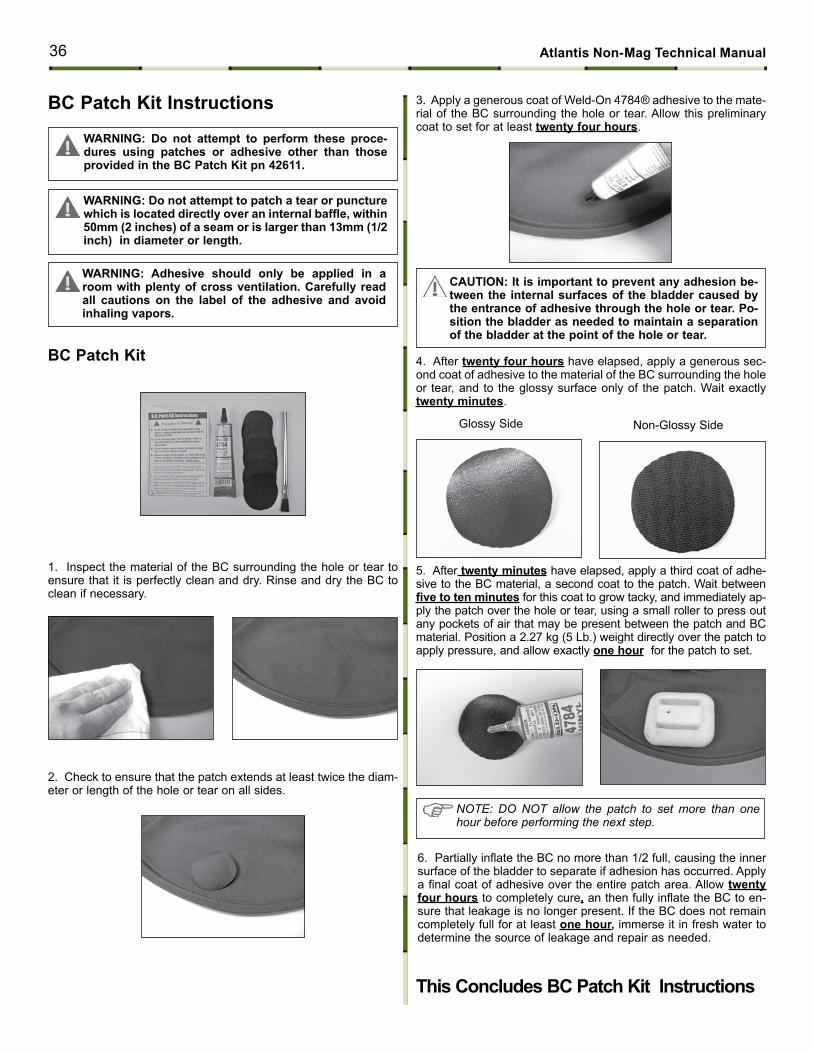
Bc Patch Kit 4. After twenty four hours have elapsed, apply a generous sec-ond coat of adhesive to the material of the BC surrounding the hole or tear, and to the glossy surface only of the patch. Wait exactly twenty minutes.
Glossy Side Non-Glossy Side
2. Check to ensure that the patch extends at least twice the diam-eter or length of the hole or tear on all sides.
3. Apply a generous coat of Weld-On 4784® adhesive to the mate-rial of the BC surrounding the hole or tear. Allow this preliminary coat to set for at least twenty four hours.
WARNING: Do not attempt to perform these proce-dures using patches or adhesive other than those provided in the Bc Patch Kit pn 42611.
WARNING: Do not attempt to patch a tear or puncture which is located directly over an internal baffle, within 50mm (2 inches) of a seam or is larger than 13mm (1/2 inch) in diameter or length.
WARNING: Adhesive should only be applied in a room with plenty of cross ventilation. carefully read all cautions on the label of the adhesive and avoid inhaling vapors.
cAutIoN: It is important to prevent any adhesion be-tween the internal surfaces of the bladder caused by the entrance of adhesive through the hole or tear. Po-sition the bladder as needed to maintain a separation of the bladder at the point of the hole or tear.
5. After twenty minutes have elapsed, apply a third coat of adhe-sive to the BC material, a second coat to the patch. Wait between five to ten minutes for this coat to grow tacky, and immediately ap-ply the patch over the hole or tear, using a small roller to press out any pockets of air that may be present between the patch and BC material. Position a 2.27 kg (5 Lb.) weight directly over the patch to apply pressure, and allow exactly one hour for the patch to set.
6. Partially inflate the BC no more than 1/2 full, causing the inner surface of the bladder to separate if adhesion has occurred. Apply a final coat of adhesive over the entire patch area. Allow twenty four hours to completely cure, an then fully inflate the BC to en-sure that leakage is no longer present. If the BC does not remain completely full for at least one hour, immerse it in fresh water to determine the source of leakage and repair as needed.
this concludes Bc Patch Kit Instructions
note: Do not allow the patch to set more than one hour before performing the next step.
36 Atlantis Non-mag technical manual
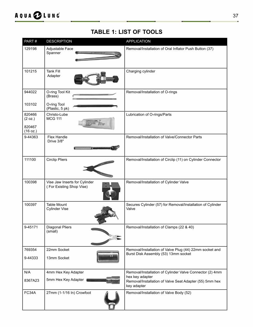
PART # DESCRIPTION APPLICATION
129198 Adjustable Face Spanner
Removal/Installation of Oral Inflator Push Button (37)
101215 Tank Fill Adapter
Charging cylinder
944022
103102
O-ring Tool Kit(Brass)
O-ring Tool(Plastic, 5 pk)
Removal/Installation of O-rings
820466 (2 oz.)
820467(16 oz.)
Christo-Lube MCG 111
Lubrication of O-rings/Parts
9-44363 Flex Handle Drive 3/8"
Removal/Installation of Valve/Connector Parts
111100 Circlip Pliers Removal/Installation of Circlip (11) on Cylinder Connector
100398 Vise Jaw Inserts for Cylinder( For Existing Shop Vise)
Removal/Installation of Cylinder Valve
100397 Table MountCylinder Vise
Secures Cylinder (57) for Removal/Installation of Cylinder Valve
9-45171 Diagonal Pliers(small)
Removal/Installation of Clamps (22 & 40)
769354
9-44333
22mm Socket
13mm Socket
Removal/Installation of Valve Plug (44) 22mm socket and Burst Disk Assembly (53) 13mm socket
N/A
8367A23
4mm Hex Key Adapter
5mm Hex Key Adapter
Removal/Installation of Cylinder Valve Connector (2) 4mm hex key adapterRemoval/Installation of Valve Seat Adapter (55) 5mm hex key adapter
FC34A 27mm (1-1/16 In) Crowfoot Removal/Installation of Valve Body (52)
tABLE 1: LISt oF tooLS
37
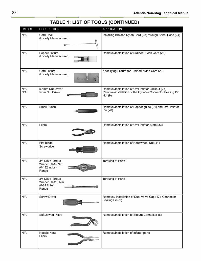
tABLE 1: LISt oF tooLS (coNtINuED)PART # DESCRIPTION APPLICATION
N/A Cord Hook(Locally Manufactured)
Installing Braided Nylon Cord (23) through Spiral Hose (24)
N/A Poppet Fixture(Locally Manufactured)
Removal/Installation of Braided Nylon Cord (23)
N/A Cord Fixture(Locally Manufactured)
Knot Tying Fixture for Braided Nylon Cord (23)
N/AN/A
5.5mm Nut Driver5mm Nut Driver
Removal/Installation of Oral Inflator Locknut (25)Removal/installation of the Cylinder Connector Sealing Pin Nut (9)
N/A Small Punch Removal/Installation of Poppet guide (21) and Oral Inflator Pin (28)
N/A Pliers Removal/Installation of Oral Inflator Stem (33)
N/A Flat Blade Screwdriver
Removal/Installation of Handwheel Nut (41)
N/A 3/8 Drive Torque Wrench; 0-15 Nm (0-132 in.lbs)Range
Torquing of Parts
N/A 3/8 Drive Torque Wrench; 0-110 Nm (0-81 ft.lbs)Range
Torquing of Parts
N/A Screw Driver Removal/ Installation of Dual Valve Cap (17), Connector Sealing Pin (9)
N/A Soft Jawed Pliers Removal/Installation to Secure Connector (6)
N/A Needle Nose Pliers
Removal/Installation of Inflator parts
38 Atlantis Non-mag technical manual
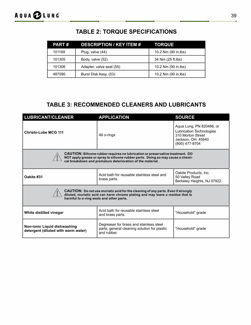
tABLE 2: toRquE SPEcIFIcAtIoNS
PARt # DEScRIPtIoN / KEY ItEm # toRquE101169 Plug, valve (44) 10.2 Nm (90 in.lbs)
101305 Body, valve (52) 34 Nm (25 ft.lbs)
101306 Adapter, valve seat (55) 10.2 Nm (90 in.lbs)
487590 Burst Disk Assy. (53) 10.2 Nm (90 in.lbs)
tABLE 3: REcommENDED cLEANERS AND LuBRIcANtS
LuBRIcANt/cLEANER APPLIcAtIoN SouRcE
christo-Lube mcG 111All o-rings
Aqua Lung, PN 820466, orLubrication Technologies 310 Morton Street Jackson, OH 45640 (800) 477-8704
oakite #31 Acid bath for reusable stainless steel and brass parts.
Oakite Products, Inc. 50 Valley Road Berkeley Heights, NJ 07922
White distilled vinegar Acid bath for reusable stainless steel and brass parts. “Household” grade
Non-ionic Liquid dishwashing detergent (diluted with warm water)
Degreaser for brass and stainless steel parts; general cleaning solution for plastic and rubber.
“Household” grade
cAutIoN: Silicone rubber requires no lubrication or preservative treatment. Do Not apply grease or spray to silicone rubber parts. Doing so may cause a chemi-cal breakdown and premature deterioration of the material.
cAutIoN: Do not use muriatic acid for the cleaning of any parts. Even if strongly diluted, muriatic acid can harm chrome plating and may leave a residue that is harmful to o-ring seals and other parts.
39
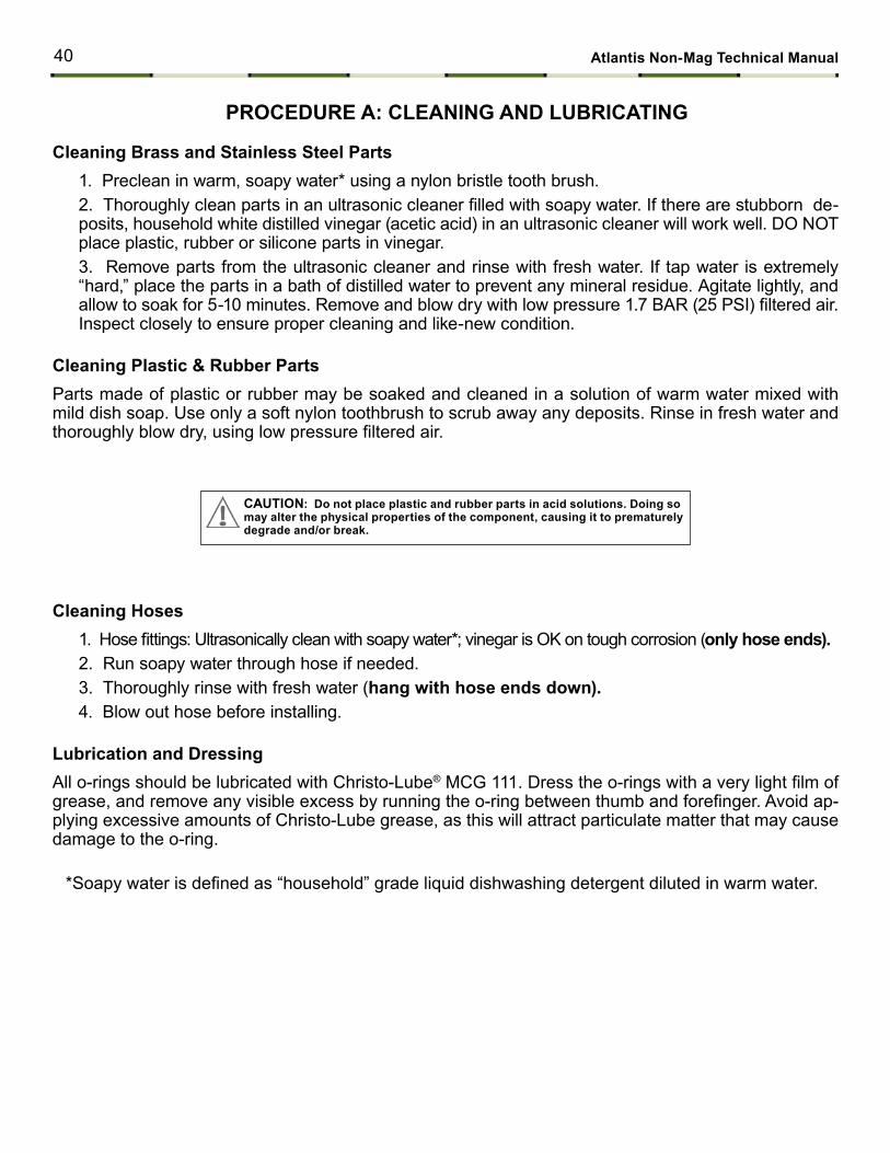
cleaning Brass and Stainless Steel Parts1. Preclean in warm, soapy water* using a nylon bristle tooth brush.2. Thoroughly clean parts in an ultrasonic cleaner filled with soapy water. If there are stubborn de-posits, household white distilled vinegar (acetic acid) in an ultrasonic cleaner will work well. DO NOT place plastic, rubber or silicone parts in vinegar.3. Remove parts from the ultrasonic cleaner and rinse with fresh water. If tap water is extremely “hard,” place the parts in a bath of distilled water to prevent any mineral residue. Agitate lightly, and allow to soak for 5-10 minutes. Remove and blow dry with low pressure 1.7 BAR (25 PSI) filtered air. Inspect closely to ensure proper cleaning and like-new condition.
cleaning Plastic & Rubber PartsParts made of plastic or rubber may be soaked and cleaned in a solution of warm water mixed with mild dish soap. Use only a soft nylon toothbrush to scrub away any deposits. Rinse in fresh water and thoroughly blow dry, using low pressure filtered air.
cleaning Hoses1. Hose fittings: Ultrasonically clean with soapy water*; vinegar is OK on tough corrosion (only hose ends).2. Run soapy water through hose if needed.3. Thoroughly rinse with fresh water (hang with hose ends down).4. Blow out hose before installing.
Lubrication and DressingAll o-rings should be lubricated with Christo-Lube® MCG 111. Dress the o-rings with a very light film of grease, and remove any visible excess by running the o-ring between thumb and forefinger. Avoid ap-plying excessive amounts of Christo-Lube grease, as this will attract particulate matter that may cause damage to the o-ring.
*Soapy water is defined as “household” grade liquid dishwashing detergent diluted in warm water.
PRocEDuRE A: cLEANING AND LuBRIcAtING
cAutIoN: Do not place plastic and rubber parts in acid solutions. Doing so may alter the physical properties of the component, causing it to prematurely degrade and/or break.
40 Atlantis Non-mag technical manual
4
5
6
78
9
10
11
2
3
Loctite 414 Superbonder
1
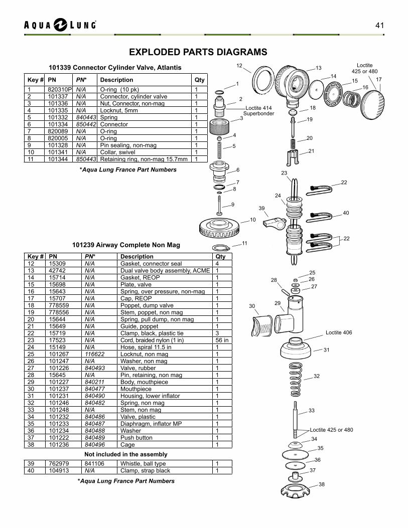
Key # PN PN* Description qty12 15309 n/A Gasket, connector seal 413 42742 n/A Dual valve body assembly, ACME 114 15714 n/A Gasket, REOP 115 15698 n/A Plate, valve 116 15643 n/A Spring, over pressure, non-mag 117 15707 n/A Cap, REOP 118 778559 n/A Poppet, dump valve 119 778556 n/A Stem, poppet, non mag 120 15644 n/A Spring, pull dump, non mag 121 15649 n/A Guide, poppet 122 15719 n/A Clamp, black, plastic tie 323 17523 n/A Cord, braided nylon (1 in) 56 in24 15149 n/A Hose, spiral 11.5 in 125 101267 116622 Locknut, non mag 126 101247 n/A Washer, non mag 127 101226 840493 Valve, rubber 128 15645 n/A Pin, retaining, non mag 129 101227 840211 Body, mouthpiece 130 101237 840477 Mouthpiece 131 101231 840490 Housing, lower inflator 132 101246 840482 Spring, non mag 133 101248 n/A Stem, non mag 134 101232 840486 Valve, plastic 135 101233 840487 Diaphragm, inflator MP 136 101234 840488 Washer 137 101222 840489 Push button 138 101236 840496 Cage 1
39 762979 841106 Whistle, ball type 140 104913 n/A Clamp, strap black 1
101239 Airway complete Non mag
Not included in the assembly
EXPLoDED PARtS DIAGRAmS12 13
14
27
31
28
2930
32
33
34
35
36
37
38
2625
40
23
22
21
19
16
18
15
Loctite 425 or 480
Loctite 406
Loctite 425 or 480
17
20
22
24
39
Key # PN PN* Description qty1 820310P n/A O-ring (10 pk) 12 101337 n/A Connector, cylinder valve 13 101336 n/A Nut, Connector, non-mag 14 101335 n/A Locknut, 5mm 15 101332 840443 Spring 16 101334 850442 Connector 17 820089 n/A O-ring 18 820005 n/A O-ring 19 101328 n/A Pin sealing, non-mag 110 101341 n/A Collar, swivel 111 101344 850443 Retaining ring, non-mag 15.7mm 1
101339 connector cylinder Valve, Atlantis
*Aqua Lung France Part Numbers
*Aqua Lung France Part Numbers
41
53
53b53c
53a
57
43
10.2 Nm
41
45
42
46474849
50
51
52
56
54
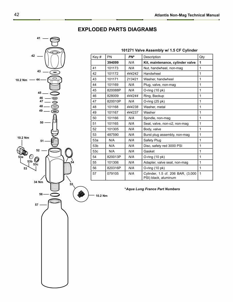
Key # PN PN* Description Qty394099 n/A Kit, maintenance, cylinder valve 1
41 101173 n/A Nut, handwheel, non-mag 142 101172 444242 Handwheel 143 101171 213421 Washer, handwheel 144 101169 n/A Plug, valve, non-mag 145 820088P n/A O-ring (10 pk) 146 828009 444244 Ring, Backup 147 820010P n/A O-ring (25 pk) 148 101168 444238 Washer, metal 149 101167 444237 Washer 150 101166 n/A Spindle, non-mag 151 101165 n/A Seat, valve, non-o2, non-mag 152 101305 n/A Body, valve 153 487590 n/A Burst plug assembly, non-mag 153a N/A n/A Safety Plug 153b N/A n/A Disc, safety red 3000 PSI 153c N/A n/A Gasket 154 820013P n/A O-ring (10 pk) 155 101306 n/A Adapter, valve seat, non-mag 156 820316P n/A O-ring (10 pk) 157 079105 n/A Cylinder, 1.5 cf. 206 BAR, (3,000
PSI) black, aluminum1
55
44
10.2 Nm
10.2 Nm
34 Nm
101271 Valve Assembly w/ 1.5 cF cylinder
EXPLoDED PARtS DIAGRAmS
*Aqua Lung France Part Numbers
42 Atlantis Non-mag technical manual
60 12
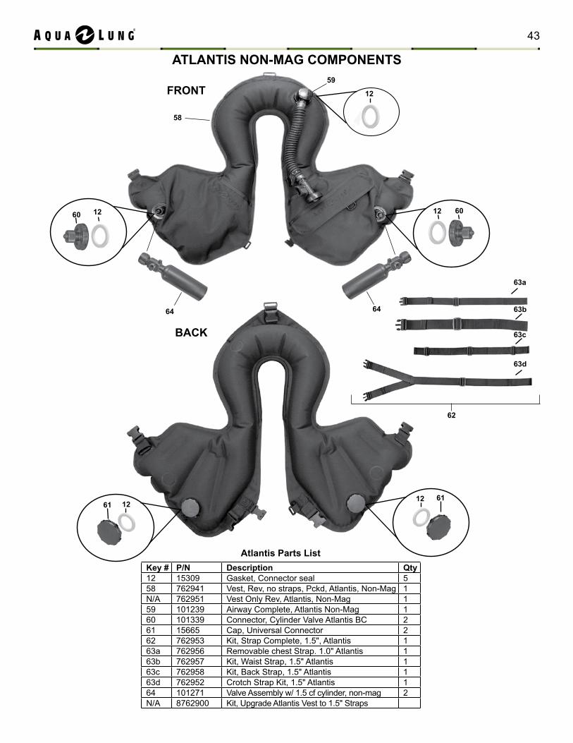
AtLANtIS NoN-mAG comPoNENtS
Key # P/N Description qty12 15309 Gasket, Connector seal 558 762941 Vest, Rev, no straps, Pckd, Atlantis, Non-Mag 1N/A 762951 Vest Only Rev, Atlantis, Non-Mag 159 101239 Airway Complete, Atlantis Non-Mag 160 101339 Connector, Cylinder Valve Atlantis BC 261 15665 Cap, Universal Connector 262 762953 Kit, Strap Complete, 1.5", Atlantis 163a 762956 Removable chest Strap. 1.0" Atlantis 163b 762957 Kit, Waist Strap, 1.5" Atlantis 163c 762958 Kit, Back Strap, 1.5" Atlantis 163d 762952 Crotch Strap Kit, 1.5" Atlantis 164 101271 Valve Assembly w/ 1.5 cf cylinder, non-mag 2N/A 8762900 Kit, Upgrade Atlantis Vest to 1.5" Straps
Atlantis Parts List
FRoNt
BAcK
58
59
63b
62
63a
63c
63d
12
6012
616112
12
64 64
43
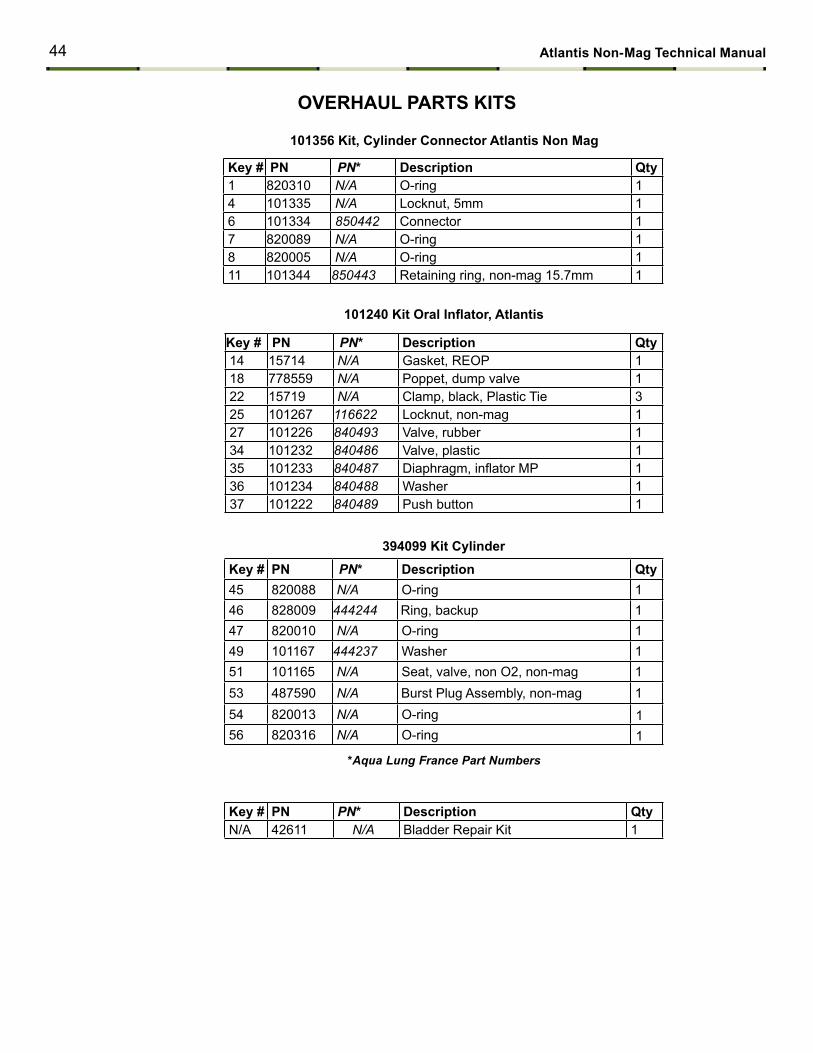
oVERHAuL PARtS KItS
Key # PN PN* Description qty 1 820310 n/A O-ring 1 4 101335 n/A Locknut, 5mm 1 6 101334 850442 Connector 1 7 820089 n/A O-ring 1 8 820005 n/A O-ring 1 11 101344 850443 Retaining ring, non-mag 15.7mm 1
101356 Kit, cylinder connector Atlantis Non mag
Key # PN PN* Description qty 14 15714 n/A Gasket, REOP 1 18 778559 n/A Poppet, dump valve 1 22 15719 n/A Clamp, black, Plastic Tie 3 25 101267 116622 Locknut, non-mag 1 27 101226 840493 Valve, rubber 1 34 101232 840486 Valve, plastic 1 35 101233 840487 Diaphragm, inflator MP 1 36 101234 840488 Washer 1 37 101222 840489 Push button 1
101240 Kit Oral Inflator, Atlantis
Key # PN PN* Description qty 45 820088 n/A O-ring 1 46 828009 444244 Ring, backup 1 47 820010 n/A O-ring 1 49 101167 444237 Washer 1 51 101165 n/A Seat, valve, non O2, non-mag 1 53 487590 n/A Burst Plug Assembly, non-mag 1 54 820013 n/A O-ring 1 56 820316 n/A O-ring 1
394099 Kit cylinder
*Aqua Lung France Part Numbers
Key # PN PN* Description qty N/A 42611 n/A Bladder Repair Kit 1
44 Atlantis Non-mag technical manual
References762970: BC, Atlantis, Military w/ Cyl Non-Mag, Rev 762980: BC, Atlantis, Military w/o Cyl Non-Mag, Rev
Accessories 101271......... Valve Assembly w/ 1.5 cf (43L) Cylinder, Non-Mag 394091......... Kit, Open Circuit, Atlantis Consists of: 15665 - Cap, Universal Connector (2) 44825 - Low Pressure Hose 25" 394039-Buckle Assembly, Double Male, 25mm 42746- Airway Complete, Powerline 15665.......... Cap, Universal Connector (for use without cylinder) 101215........ Adapter Tank Fill. Atlantis BC
tEcHNIcAL DAtA
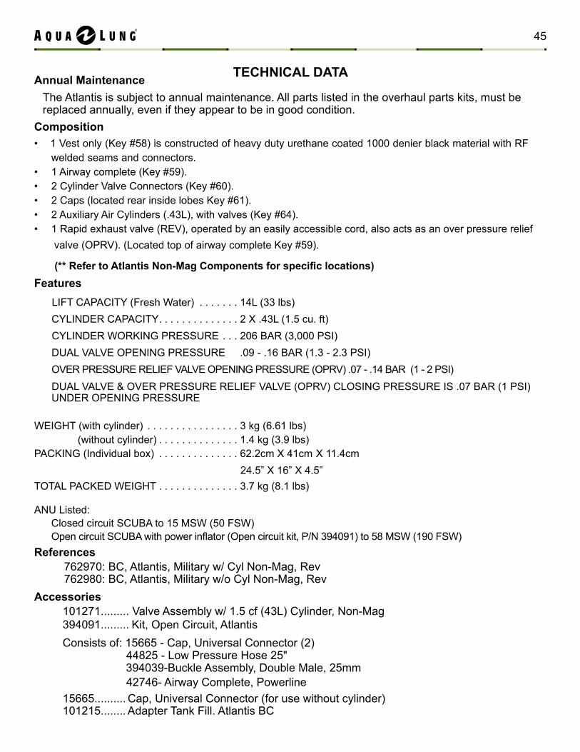
composition 1 Vest only (Key #58) is constructed of heavy duty urethane coated 1000 denier black material with RF • welded seams and connectors.1 Airway complete (Key #59).• 2 Cylinder Valve Connectors (Key #60).• 2 Caps (located rear inside lobes Key #61).• 2 Auxiliary Air Cylinders (.43L), with valves (Key #64).• 1 Rapid exhaust valve (REV), operated by an easily accessible cord, also acts as an over pressure relief • valve (OPRV). (Located top of airway complete Key #59).
(** Refer to Atlantis Non-Mag Components for specific locations)Features LIFT CAPACITY (Fresh Water) . . . . . . . 14L (33 lbs) CYLINDER CAPACITY. . . . . . . . . . . . . . 2 X .43L (1.5 cu. ft) CYLINDER WORKING PRESSURE . . . 206 BAR (3,000 PSI) DUAL VALVE OPENING PRESSURE .09 - .16 BAR (1.3 - 2.3 PSI) OVER PRESSURE RELIEF VALVE OPENING PRESSURE (OPRV) .07 - .14 BAR (1 - 2 PSI) DUAL VALVE & OVER PRESSURE RELIEF VALVE (OPRV) CLOSING PRESSURE IS .07 BAR (1 PSI) UNDER OPENING PRESSURE
WEIGHT (with cylinder) . . . . . . . . . . . . . . . . 3 kg (6.61 lbs) (without cylinder) . . . . . . . . . . . . . . 1.4 kg (3.9 lbs)PACKING (Individual box) . . . . . . . . . . . . . . 62.2cm X 41cm X 11.4cm 24.5” X 16” X 4.5”TOTAL PACKED WEIGHT . . . . . . . . . . . . . . 3.7 kg (8.1 lbs)
ANU Listed:Closed circuit SCUBA to 15 MSW (50 FSW)Open circuit SCUBA with power inflator (Open circuit kit, P/N 394091) to 58 MSW (190 FSW)
Annual maintenanceThe Atlantis is subject to annual maintenance. All parts listed in the overhaul parts kits, must be replaced annually, even if they appear to be in good condition.
45
mAINtENANcE NotES
46 Atlantis Non-mag technical manual
WARNING: It is dangerous for untrained and uncertified persons to use the equipment covered by this warranty. therefore, use of these prod-ucts by an untrained person renders any and all warranties null and void. Use of SCUBA equipment by anyone who is not a certified diver, or receiving training through a recognized certification agency, shall render void all warranties, expressed or implied.
Restrictions The following restrictions apply to this warranty:
This warranty extends to inflator parts, and to the seams of the BC bladder. Factory prescribed • annual service by a trained technician is required.This warranty does not extend to abrasion, punctures, or tears of the bladder, or seam separation • caused by chemical attack; including prolonged exposure to chlorine.This warranty does not extend to damages caused by improper use, improper • maintenance, neglect, unauthorized repairs, modifications, accidents, fire, or casualty.Cosmetic damage, such as scratches, fraying, and nicks are not covered by this warranty.• This warranty covers products purchased in the United States. For warranties that may apply • elsewhere, please contact your local representative.Failure to meet any of the above requirements will render the warranty null and void.•
WARRANtY INFoRmAtIoNAll warranty transactions must be accompanied by proof of original purchase from an Aqua Lung® autho-rized dealer/agent. Be sure to save your sales receipt, and present it whenever returning your Atlantis for warranty service.the Aqua Lung® one Year Limited Warranty™
Aqua Lung America warrants to the original purchaser for a period of one year from the date of purchase that the product will be free from defects in material and workmanship; provided that it receives normal use, proper care, and prescribed dealer service subject to those restrictions stated below. This limited warranty is extended only to the original purchaser for purchases made from an authorized Aqua Lung®
dealer, and is not transferable. This warranty is limited to repair or replacement only at the discretion of Aqua Lung America, Inc.
ALL WARRANtIES, INcLuDING, But Not LImItED to, ImPLIED WARRANtIES, oR mERcHANtABILItY AND FItNESS FoR A PARtIcuLAR PuRPoSE ARE LImItED IN
DuRAtIoN to A PERIoD ENDING oNE YEAR FRom tHE DAtE oF PuRcHASE.
AquA LuNG AmERIcA DIScLAImS AND EXcLuDES ANY LIABILItY FoR INcIDENtAL, oR coNSEquENtIAL DAmAGES. SomE StAtES Do Not ALLoW EXcLuSIoNS oF
LIABILItY, So tHIS mAY Not APPLY to You.
47

©2011 Aqua Lung International
2340 Cousteau Court • Vista, CA 92081Phone (760) 597-5000 • Fax (760) 597-4900www.aqualung.com/militaryandprofessional
Literature P/N 762988 Rev. 10/11
ATLANTIS
NON-MAGNETIC


![Military Tech Bulletin - Aqua Lung US - Aqua Lung US - … · · 2017-09-05Title: Microsoft Word - WTX Inflator Adapter Tech Bulletin FINAL 083017[1].docx Author: Shawn Haight Created](https://img.pdfslide.us/doc/110x75/5affabba7f8b9a6a2e8b8865/military-tech-bulletin-aqua-lung-us-aqua-lung-us-microsoft-word-wtx.jpg)