Embed Size (px)
Citation preview

Above-Ground Pool Automationby
LDC
G LINEON TROLS
Aqua TrolAqua TrolAqua TrolAqua TrolAqua Trol®
Refer to www.goldlinecontrols.com for latest manualrevisions, additional information and helpful service.
ELECTROLYTIC CHLORINE GENERATORBASIC POOL MAINTENANCE REQUIREMENTS
North Kingstown, RI 02852 USA
WE
EK
LYM
ON
THLY
QU
ARTE
RLY
LDC
G LINEON TROLS
092016KCopyright © 2009 Goldine Controls
AQ-TROL
Free Chlorine 1.0 - 3.0 ppm Turn output dial up to increase, pH 7.2 - 7.8
down to decrease -OR- increase
Too low - add soda ash.
or decrease pump filtration time.
Too high - add muriatic acid
Alkalinity 80 - 120 ppm
Salt 2700 - 3400 ppm Add salt as required to increase.
Add baking soda to increase.
Stabilizer 60 - 80 ppm Add cyanuric acid to increase.
Calcium 200 - 400 ppm Add calcium to increase. Electrolytic Cell inspect & clean Refer to section in manual.
TEST IDEAL RANGE ADJUSTMENT REQUIRED
Drain and add water to decrease.
Add acid as required to decrease.
www.goldlinecontrols.com LD
CG LINE
ON TROLS
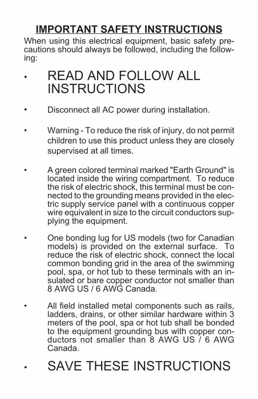
IMPORTANT SAFETY INSTRUCTIONSWhen using this electrical equipment, basic safety pre-cautions should always be followed, including the follow-ing:
• READ AND FOLLOW ALLINSTRUCTIONS
• Disconnect all AC power during installation.
• Warning - To reduce the risk of injury, do not permitchildren to use this product unless they are closelysupervised at all times.
• A green colored terminal marked "Earth Ground" islocated inside the wiring compartment. To reducethe risk of electric shock, this terminal must be con-nected to the grounding means provided in the elec-tric supply service panel with a continuous copperwire equivalent in size to the circuit conductors sup-plying the equipment.
• One bonding lug for US models (two for Canadianmodels) is provided on the external surface. Toreduce the risk of electric shock, connect the localcommon bonding grid in the area of the swimmingpool, spa, or hot tub to these terminals with an in-sulated or bare copper conductor not smaller than8 AWG US / 6 AWG Canada.
• All field installed metal components such as rails,ladders, drains, or other similar hardware within 3meters of the pool, spa or hot tub shall be bondedto the equipment grounding bus with copper con-ductors not smaller than 8 AWG US / 6 AWGCanada.
• SAVE THESE INSTRUCTIONS16

Table of Contents
OPERATIONOPERATIONOPERATIONOPERATIONOPERATIONThe Aqua TrolThe Aqua TrolThe Aqua TrolThe Aqua TrolThe Aqua Trol®®®®®...........................................................................................1
Water Chemistry....Water Chemistry....Water Chemistry....Water Chemistry....Water Chemistry.....................................................................1
Controls . . . . . . . . . . . . . . . . . . . . . . . . . . . . . . . . . . . . . . . . . . . . . . . . . . . . . . . . . . . . . . . . . . . .Controls . . . . . . . . . . . . . . . . . . . . . . . . . . . . . . . . . . . . . . . . . . . . . . . . . . . . . . . . . . . . . . . . . . . .Controls . . . . . . . . . . . . . . . . . . . . . . . . . . . . . . . . . . . . . . . . . . . . . . . . . . . . . . . . . . . . . . . . . . . .Controls . . . . . . . . . . . . . . . . . . . . . . . . . . . . . . . . . . . . . . . . . . . . . . . . . . . . . . . . . . . . . . . . . . . .Controls . . . . . . . . . . . . . . . . . . . . . . . . . . . . . . . . . . . . . . . . . . . . . . . . . . . . . . . . . . . . . . . . . . . .6
Maintenance.. . . . . . . . . . . . . . . . . . . . . . . . . . . . . . . . . . . . . . . . . . . . . . . . . . . . . . .Maintenance.. . . . . . . . . . . . . . . . . . . . . . . . . . . . . . . . . . . . . . . . . . . . . . . . . . . . . . .Maintenance.. . . . . . . . . . . . . . . . . . . . . . . . . . . . . . . . . . . . . . . . . . . . . . . . . . . . . . .Maintenance.. . . . . . . . . . . . . . . . . . . . . . . . . . . . . . . . . . . . . . . . . . . . . . . . . . . . . . .Maintenance.. . . . . . . . . . . . . . . . . . . . . . . . . . . . . . . . . . . . . . . . . . . . . . . . . . . . . . . . . . . . . . . .8.
INSTALLATIONINSTALLATIONINSTALLATIONINSTALLATIONINSTALLATIONMounting. . . . . . . . . . . . . . . . . . . . . . . . . . . . . . . . . . . . . . . . . . . . . . . . . . . . . . . . . . . . . . . . . . . .Mounting. . . . . . . . . . . . . . . . . . . . . . . . . . . . . . . . . . . . . . . . . . . . . . . . . . . . . . . . . . . . . . . . . . . .Mounting. . . . . . . . . . . . . . . . . . . . . . . . . . . . . . . . . . . . . . . . . . . . . . . . . . . . . . . . . . . . . . . . . . . .Mounting. . . . . . . . . . . . . . . . . . . . . . . . . . . . . . . . . . . . . . . . . . . . . . . . . . . . . . . . . . . . . . . . . . . .Mounting. . . . . . . . . . . . . . . . . . . . . . . . . . . . . . . . . . . . . . . . . . . . . . . . . . . . . . . . . . . . . . . . . . . .9
Plumbing. . . . . . . . . . . . . . . . . . . . . . . . . . . . . . . . . . . . . . . . . . . . . . . . . . . . . . . . . . . . . .Plumbing. . . . . . . . . . . . . . . . . . . . . . . . . . . . . . . . . . . . . . . . . . . . . . . . . . . . . . . . . . . . . .Plumbing. . . . . . . . . . . . . . . . . . . . . . . . . . . . . . . . . . . . . . . . . . . . . . . . . . . . . . . . . . . . . .Plumbing. . . . . . . . . . . . . . . . . . . . . . . . . . . . . . . . . . . . . . . . . . . . . . . . . . . . . . . . . . . . . .Plumbing. . . . . . . . . . . . . . . . . . . . . . . . . . . . . . . . . . . . . . . . . . . . . . . . . . . . . . . . . . . . . . . . . . . . .10
Wiring. . . . . . . . . . . . . . . . . . . . . . . . . . . . . . . . . . . . . . . . . . . . . . . . . . . . . . . . . . . . . .Wiring. . . . . . . . . . . . . . . . . . . . . . . . . . . . . . . . . . . . . . . . . . . . . . . . . . . . . . . . . . . . . .Wiring. . . . . . . . . . . . . . . . . . . . . . . . . . . . . . . . . . . . . . . . . . . . . . . . . . . . . . . . . . . . . .Wiring. . . . . . . . . . . . . . . . . . . . . . . . . . . . . . . . . . . . . . . . . . . . . . . . . . . . . . . . . . . . . .Wiring. . . . . . . . . . . . . . . . . . . . . . . . . . . . . . . . . . . . . . . . . . . . . . . . . . . . . . . . . . . . . . . . . . . . . . . . .11
TROUBLESHOOTINGTROUBLESHOOTINGTROUBLESHOOTINGTROUBLESHOOTINGTROUBLESHOOTINGTroubleshooting.... . . . . . . . . . . . . . . . . . . . . . . . . . . . . . . . .Troubleshooting.... . . . . . . . . . . . . . . . . . . . . . . . . . . . . . . . .Troubleshooting.... . . . . . . . . . . . . . . . . . . . . . . . . . . . . . . . .Troubleshooting.... . . . . . . . . . . . . . . . . . . . . . . . . . . . . . . . .Troubleshooting.... . . . . . . . . . . . . . . . . . . . . . . . . . . . . . . . . .........................13
WARRANTYWARRANTYWARRANTYWARRANTYWARRANTYWarranty.... . . . . . . . . . . . . . . . . . . . . . . . . . . . . . . . . . . . . . . .Warranty.... . . . . . . . . . . . . . . . . . . . . . . . . . . . . . . . . . . . . . . .Warranty.... . . . . . . . . . . . . . . . . . . . . . . . . . . . . . . . . . . . . . . .Warranty.... . . . . . . . . . . . . . . . . . . . . . . . . . . . . . . . . . . . . . . .Warranty.... . . . . . . . . . . . . . . . . . . . . . . . . . . . . . . . . . . . . . . . .............................15
15
LIMITED WARRANTY (effective 04/01/09) Hayward/Goldline warrants its Pro Logic andE-Command pool automation products as well as its Aqua Rite, Aqua Rite Pro, Aqua Plus andSwimPure chlorination products to be free of defects in materials and workmanship, undernormal use and service, for a period of three (3) years. Hayward/Goldline also warrants itsAqua Trol chlorination products to be free of defects in materials and workmanship, undernormal use and service for a period of one (1) year. These warranties are applicable from theinitial date of installation on private residential swimming pools in the US and Canada.
Hayward/Goldline warrants all the above-identified pool automation and chlorination prod-ucts installed on commercial swimming pools and on swimming pools outside of the US andCanada for a period of one (1) year. Likewise, Hayward/Goldline warrants all accessoriesand replacement parts for the above-identified pool automation and chlorination products fora period of one (1) year. Each of these warranties is not transferable and applies only to theoriginal owner.
Proof of purchase is required for warranty service. If written proof of purchase is notprovided, the manufacturing date code will be the sole determinant of the date of installationof the product. To obtain warranty service or repair, please contact the place of purchase orthe nearest Hayward/Goldline authorized warranty service center. For more information onauthorized service centers please contact the Hayward/Goldline Technical Service SupportCenter (61 Whitecap Road, North Kingstown RI, 02852) or visit the Goldline web site atwww.goldlinecontrols.com or the Hayward website at www.haywardnet.com.
WARRANTY EXCLUSIONS:1. Material supplied or workmanship performed by others in process of installation.
2. Damage resulting from improper installation including installation on pools larger than theproduct rating.
3. Problems resulting from failure to install, operate or maintain the product(s) in accordancewith the recommendations contained in the owners manual(s).
4. Problems resulting from failure to maintain pool water chemistry in accordance with therecommendations in the owners manual(s).
5. Problems resulting from tampering, accident, abuse, negligence, unauthorized repairs oralternations, fire, flood, lightning, freezing, external water, degradation of natural stone used inor immediately adjacent to a pool or spa, war or acts of God.
DISCLAIMER. THE EXPRESS LIMITED WARRANTIES ABOVE CONSTITUTE THEENTIRE WARRANTIES WITH RESPECT TO THE ABOVE-IDENTIFIED HAYWARD/GOLDLINE POOL AUTOMATION AND CHLORINATION PRODUCTS AND IS INLIEU OF ALL OTHER WARRANTIES, EXPRESS OR IMPLIED, INCLUDING WAR-RANTIES OF MERCHANTABILITY OR FITNESS FOR A PARTICULAR PURPOSE.THESE WARRANTIES GIVE YOU SPECIFIC LEGAL RIGHTS, AND YOU MAY ALSOHAVE OTHER RIGHTS OF EQUIPMENT, LOST PROFITS OR REVENUE, COSTSOF RENTING REPLACEMENTS, AND OTHER ADDITIONAL EXPENSES, EVEN IFTHE SELLER HAD BEEN ADVISED OF THE POSSIBILITY OF SUCH DAMAGES.SOME STATES DO NOT ALLOW THE EXCLUSION OF LIMITATION OF INCI-DENTAL OR CONSEQUENTIAL DAMAGES, SO THE ABOVE LIMITATION OREXCLUSION MAY NOT APPLY TO YOU.
NO WHOLESALER, AGENT, DEALER, CONTRACTOR OR OTHER PERSON ISAUTHORIZED TO PROVIDE, SUPPLEMENT OR MODIFY ANY WARRANTY ONBEHALF OF HAYWARD/GOLDLINE.
THESE WARRANTIES ARE VOID IF THE PRODUCT HAS BEEN ALTERED IN ANYWAY AFTER LEAVING THE FACTORY. FOR THE ABOVE-IDENTIFIED CHLORI-NATION PRODUCTS, THESE WARRANTIES ALSO ARE VOID IF, DURING THEWARRANTY PERIOD, YOU USE A REPLACEMENT CHLORINATOR CELL OTHERTHAN AN UNMODIFIED, NEW HAYWARD/GOLDLINE CHLORINATOR CELL PUR-CHASED FROM HAYWARD/GOLDLINE. IF A WARRANTY BECOMES VOID, YOUSTILL MAY PURCHASE SERVICE AND/OR TELEPHONE TECHNICAL SUPPORTAT THE THENCURRENT TIME AND MATERIAL RATES.
1
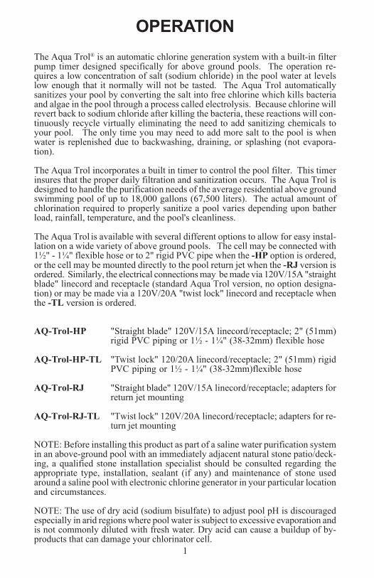
OPERATIONThe Aqua Trol® is an automatic chlorine generation system with a built-in filterpump timer designed specifically for above ground pools. The operation re-quires a low concentration of salt (sodium chloride) in the pool water at levelslow enough that it normally will not be tasted. The Aqua Trol automaticallysanitizes your pool by converting the salt into free chlorine which kills bacteriaand algae in the pool through a process called electrolysis. Because chlorine willrevert back to sodium chloride after killing the bacteria, these reactions will con-tinuously recycle virtually eliminating the need to add sanitizing chemicals toyour pool. The only time you may need to add more salt to the pool is whenwater is replenished due to backwashing, draining, or splashing (not evapora-tion).
The Aqua Trol incorporates a built in timer to control the pool filter. This timerinsures that the proper daily filtration and sanitization occurs. The Aqua Trol isdesigned to handle the purification needs of the average residential above groundswimming pool of up to 18,000 gallons (67,500 liters). The actual amount ofchlorination required to properly sanitize a pool varies depending upon batherload, rainfall, temperature, and the pool's cleanliness.
The Aqua Trol is available with several different options to allow for easy instal-lation on a wide variety of above ground pools. The cell may be connected with1½" - 1¼" flexible hose or to 2" rigid PVC pipe when the -HP option is ordered,or the cell may be mounted directly to the pool return jet when the -RJ version isordered. Similarly, the electrical connections may be made via 120V/15A "straightblade" linecord and receptacle (standard Aqua Trol version, no option designa-tion) or may be made via a 120V/20A "twist lock" linecord and receptacle whenthe -TL version is ordered.
AQ-Trol-HP "Straight blade" 120V/15A linecord/receptacle; 2" (51mm)rigid PVC piping or 1½ - 1¼" (38-32mm) flexible hose
AQ-Trol-HP-TL "Twist lock" 120/20A linecord/receptacle; 2" (51mm) rigidPVC piping or 1½ - 1¼" (38-32mm)flexible hose
AQ-Trol-RJ "Straight blade" 120V/15A linecord/receptacle; adapters forreturn jet mounting
AQ-Trol-RJ-TL "Twist lock" 120V/20A linecord/receptacle; adapters for re-turn jet mounting
NOTE: Before installing this product as part of a saline water purification systemin an above-ground pool with an immediately adjacent natural stone patio/deck-ing, a qualified stone installation specialist should be consulted regarding theappropriate type, installation, sealant (if any) and maintenance of stone usedaround a saline pool with electronic chlorine generator in your particular locationand circumstances.
NOTE: The use of dry acid (sodium bisulfate) to adjust pool pH is discouragedespecially in arid regions where pool water is subject to excessive evaporation andis not commonly diluted with fresh water. Dry acid can cause a buildup of by-products that can damage your chlorinator cell.
14
of the control unit and that the wire is not cut or damaged. Make sure you have atleast 12" of straight pipe before the flow switch. If there is adequate flow and theLED is still on, check that the arrows on the flow switch (on top of hex) are pointingin the direction of flow.
6. "Test Salt Level" LED illuminated or flashingTake a sample of your pool water to your local Authorized Aqua Rite Dealer andhave the salt level tested. No salt test is completely accurate and the test resultsmay vary from the salt level on the Aqua Trol display. If salt level is low, add saltaccording to chart on page 4.
7. "High Salt" LED illuminatedCheck salt level in pool/spa. If salt level is too high, lower salt level by drainingsome of the pool water out of the pool and replace with fresh water. Continueuntil the salt concentration is at recommended levels.
8. "Inspect Cell" LED flashingInspect and clean cell according to directions on page 8. When done, press the"diagnostic" button for 3 seconds to stop the "Inspect Cell" LED flashing.
9. "Inspect Cell" LED illuminatedRemove and inspect the cell for scale. If the cell is scaled, follow the directionson page 8 for cell cleaning. If the pool has the proper amount of salt and the"Inspect Cell" LED is still illuminated, the cell may be worn and need replace-ment.
10. Possible causes of little or no free chlorine residual- Aqua Trol switch in OFF position.- Desired Level % adjustment setting is too low.- Low stabilizer (Cyanuric Acid).- Filter pump switched off or filter pump time too short (8 hours for average size
pools, more for large pools)- Salt level too low (below 2500 ppm, Low Salt LED on).- Salt level too high (High Salt LED on).- Very warm pools increase chlorine demand--increase Desired Level % or filter
run time.- Cold water (below 50F) causes Aqua Trol to stop generating (Generating LED
flashing).- Excessive scaling on cell.- High level of Nitrogen in pool water.- "Yellow Out" or similar treatment recently used. Some yellow algae treatments
will use chlorine at a very high rate and deplete the residual free chlorine.Manually shock the pool if indicated in the directions on the algae treatment. Itstill may be a matter of days before the pool returns to "normal" and chlorinetests will show the desired 1-3ppm free chlorine reading.
11. "-Pcb-" displayed and all 4 red/yellow LEDs are illuminated.A possible Printed Circuit Board fault has been detected.
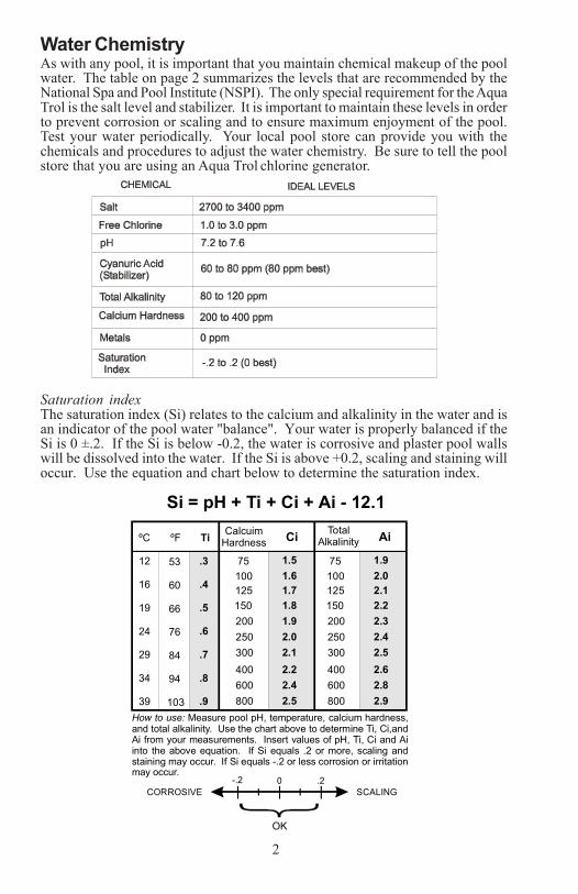
Water ChemistryAs with any pool, it is important that you maintain chemical makeup of the poolwater. The table on page 2 summarizes the levels that are recommended by theNational Spa and Pool Institute (NSPI). The only special requirement for the AquaTrol is the salt level and stabilizer. It is important to maintain these levels in orderto prevent corrosion or scaling and to ensure maximum enjoyment of the pool.Test your water periodically. Your local pool store can provide you with thechemicals and procedures to adjust the water chemistry. Be sure to tell the poolstore that you are using an Aqua Trol chlorine generator.
Saturation indexThe saturation index (Si) relates to the calcium and alkalinity in the water and isan indicator of the pool water "balance". Your water is properly balanced if theSi is 0 ±.2. If the Si is below -0.2, the water is corrosive and plaster pool wallswill be dissolved into the water. If the Si is above +0.2, scaling and staining willoccur. Use the equation and chart below to determine the saturation index.
2
ºC ºF Ti CalcuimHardness Ci Total
Alkalinity Ai
53
60
66
76
84
94
103
12
16
19
24
29
34
39
.3
.4
.5
.6
.7
.8
.9How to use: Measure pool pH, temperature, calcium hardness,and total alkalinity. Use the chart above to determine Ti, Ci,andAi from your measurements. Insert values of pH, Ti, Ci and Aiinto the above equation. If Si equals .2 or more, scaling and staining may occur. If Si equals -.2 or less corrosion or irritationmay occur.
Si = pH + Ti + Ci + Ai - 12.1
-.2 0 .2CORROSIVE SCALING
75 75100 100125 125150 150200 200250 250300 300400 400600 600800 800
1.5 1.91.6 2.01.7 2.11.8 2.21.9 2.32.0 2.42.1 2.52.2 2.62.4 2.82.5 2.9
OK
13
Troubleshooting
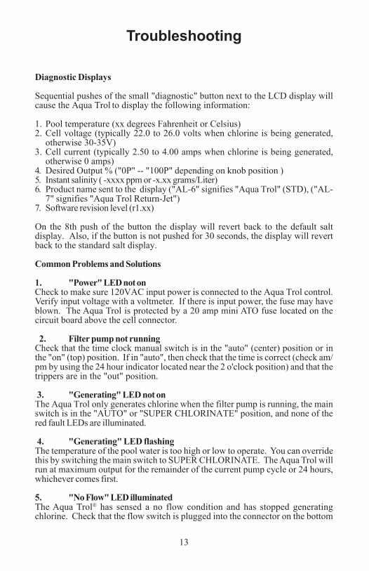
Diagnostic Displays
Sequential pushes of the small "diagnostic" button next to the LCD display willcause the Aqua Trol to display the following information:
1. Pool temperature (xx degrees Fahrenheit or Celsius)2. Cell voltage (typically 22.0 to 26.0 volts when chlorine is being generated,
otherwise 30-35V)3. Cell current (typically 2.50 to 4.00 amps when chlorine is being generated,
otherwise 0 amps)4. Desired Output % ("0P" -- "100P" depending on knob position )5. Instant salinity ( -xxxx ppm or -x.xx grams/Liter)6. Product name sent to the display ("AL-6" signifies "Aqua Trol" (STD), ("AL-
7" signifies "Aqua Trol Return-Jet")7. Software revision level (r1.xx)
On the 8th push of the button the display will revert back to the default saltdisplay. Also, if the button is not pushed for 30 seconds, the display will revertback to the standard salt display.
Common Problems and Solutions
1. "Power" LED not onCheck to make sure 120VAC input power is connected to the Aqua Trol control.Verify input voltage with a voltmeter. If there is input power, the fuse may haveblown. The Aqua Trol is protected by a 20 amp mini ATO fuse located on thecircuit board above the cell connector.
2. Filter pump not runningCheck that the time clock manual switch is in the "auto" (center) position or inthe "on" (top) position. If in "auto", then check that the time is correct (check am/pm by using the 24 hour indicator located near the 2 o'clock position) and that thetrippers are in the "out" position.
3. "Generating" LED not onThe Aqua Trol only generates chlorine when the filter pump is running, the mainswitch is in the "AUTO" or "SUPER CHLORINATE" position, and none of thered fault LEDs are illuminated.
4. "Generating" LED flashingThe temperature of the pool water is too high or low to operate. You can overridethis by switching the main switch to SUPER CHLORINATE. The Aqua Trol willrun at maximum output for the remainder of the current pump cycle or 24 hours,whichever comes first.
5. "No Flow" LED illuminatedThe Aqua Trol® has sensed a no flow condition and has stopped generatingchlorine. Check that the flow switch is plugged into the connector on the bottom
3
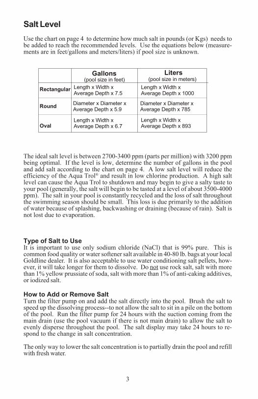
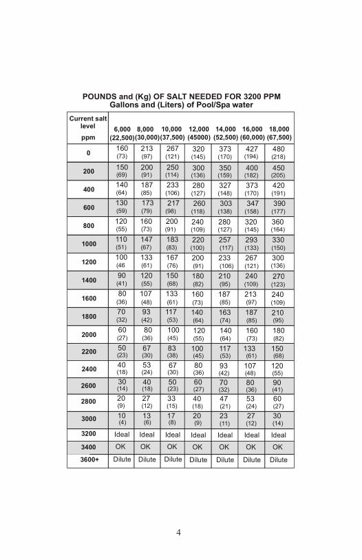
Salt LevelUse the chart on page 4 to determine how much salt in pounds (or Kgs) needs tobe added to reach the recommended levels. Use the equations below (measure-ments are in feet/gallons and meters/liters) if pool size is unknown.
The ideal salt level is between 2700-3400 ppm (parts per million) with 3200 ppmbeing optimal. If the level is low, determine the number of gallons in the pooland add salt according to the chart on page 4. A low salt level will reduce theefficiency of the Aqua Trol® and result in low chlorine production. A high saltlevel can cause the Aqua Trol to shutdown and may begin to give a salty taste toyour pool (generally, the salt will begin to be tasted at a level of about 3500-4000ppm). The salt in your pool is constantly recycled and the loss of salt throughoutthe swimming season should be small. This loss is due primarily to the additionof water because of splashing, backwashing or draining (because of rain). Salt isnot lost due to evaporation.
Type of Salt to UseIt is important to use only sodium chloride (NaCl) that is 99% pure. This iscommon food quality or water softener salt available in 40-80 lb. bags at your localGoldline dealer. It is also acceptable to use water conditioning salt pellets, how-ever, it will take longer for them to dissolve. Do not use rock salt, salt with morethan 1% yellow prussiate of soda, salt with more than 1% of anti-caking additives,or iodized salt.
How to Add or Remove SaltTurn the filter pump on and add the salt directly into the pool. Brush the salt tospeed up the dissolving process--to not allow the salt to sit in a pile on the bottomof the pool. Run the filter pump for 24 hours with the suction coming from themain drain (use the pool vacuum if there is not main drain) to allow the salt toevenly disperse throughout the pool. The salt display may take 24 hours to re-spond to the change in salt concentration.
The only way to lower the salt concentration is to partially drain the pool and refillwith fresh water.
12
Gallons Liters(pool size in feet) (pool size in meters)
Rectangular
Round
Oval
Diameter x Diameter x Average Depth x 5.9
Length x Width x Average Depth x 6.7
Length x Width x Average Depth x 7.5
Diameter x Diameter x Average Depth x 785
Length x Width x Average Depth x 893
Length x Width x Average Depth x 1000
BondingA lug used for bonding is attached to the bottom of the Aqua Trol enclosure.Connect to the pool bonding system using minimum 8AWG copper wire if re-quired by code.
Pump OutputThe Aqua Trol's filter pump output is rated at 120 VAC, 15 A max. Check theelectrical rating marked on the pump motor. Connecting a pump with a higheramperage rating may result in permanent damage to the Aqua Trol. The 120VAC standard or twist lock pump receptacle is located outside, on the bottom ofthe enclosure.
Electrolytic Cell and Flow SwitchThe cell and flow switch plug into connectors on the Aqua Trol electronics unit.Note that return jet units (-RJ option) will NOT have a flow switch. See diagrambelow.
Phone jackto flow switch
Bonding lug topool bonding system
OUTPUT POWER120 VAC receptacle
to pool pump
INPUT POWER120 VAC linecord
to GFCI receptacle/breaker
Cutout forcell cable
4
Gallons and (Liters) of Pool/Spa water
12,000 14,000 16,000 18,000Current salt
level(45000) (52,500) (60,000) (67,500)ppm
0 320 (145)
373 (170)
427 (194)
480 (218)
200 300 (136)
350 (159)
400 (182)
450 (205)
400 280 (127)
327 (148)
373 (170)
420 (191)
600 260 (118)
303 (138)
347 (158)
390 (177)
800 240 (109)
280 (127)
320 (145)
360 (164)
1000 220 (100)
257 (117)
293 (133)
330 (150)
1200 200 (91)
233 (106)
267 (121)
300 (136)
1400 180 (82)
210 (95)
240 (109) (123)
1600 160 (73)
187 (85)
213 (97)
240 (109)
1800 140 (64)
163 (74)
187 (85)
210 (95)
2000 120
100
80
60
20
40
(55)
(45)
(36)
(27)
(9)
(18)
140
117
23
47
(64)
(53)
(11)
(21)
160
133
27
53
(73)
(61)
(12)
(24)
180
150
30
60
(82)
(68)
(14)
(27)
(32)80 (36)
90 (41)
93 (42)
107 (48)
120 (55)
2200
3000
2800
2400
3200 Ideal Ideal Ideal Ideal
2600
3400 OKOKOK OKOK OK OK
POUNDS and (Kg) OF SALT NEEDED FOR 3200 PPM
3600+ Dilute Dilute Dilute Dilute
10,000 8,000 6,000(37,500)
213 160 267 (97)(73) (121)
200 150 250 (91)(69) (114)
187 140 233 (85)(64) (106)
173 130 217 (79)(59) (98)
160 120 200 (73)(55) (91)
147 110 183 (67)(51) (83)
133 100 167 (61)(46 (76)
120 90 150 (55)(41) (68)
107 80 133 (48)(36) (61)93 70 117 (42)(32) (53)
80 60 100
67 50 83
53 40 67
40 30 50
13 10 17
27 20 33
(36)(27) (45)
(30)(23) (38)
(24)(18) (30)
(18)(14) (23)
(6)(4) (8)
(12)(9) (15)
IdealIdeal Ideal
DiluteDilute Dilute
(30,000)(22,500)
11
Wiring
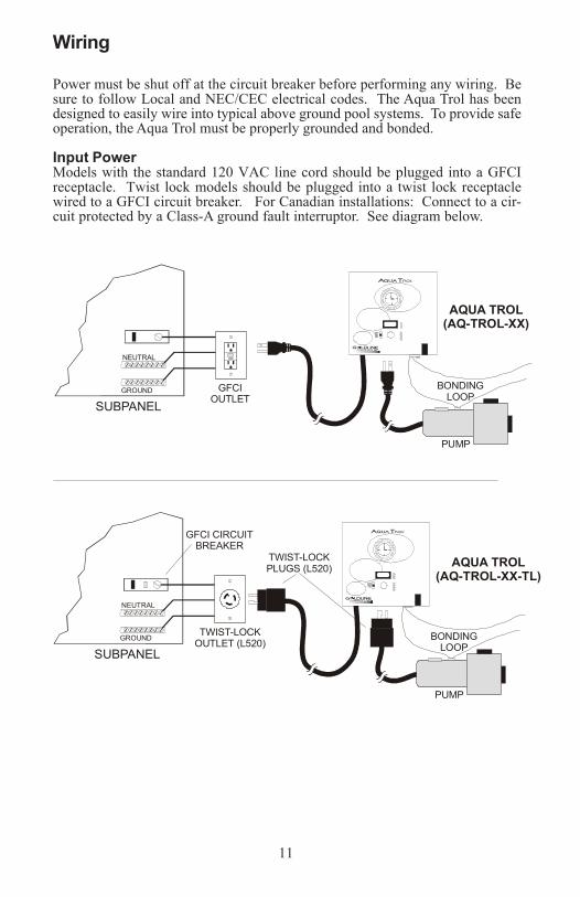
Power must be shut off at the circuit breaker before performing any wiring. Besure to follow Local and NEC/CEC electrical codes. The Aqua Trol has beendesigned to easily wire into typical above ground pool systems. To provide safeoperation, the Aqua Trol must be properly grounded and bonded.
Input PowerModels with the standard 120 VAC line cord should be plugged into a GFCIreceptacle. Twist lock models should be plugged into a twist lock receptaclewired to a GFCI circuit breaker. For Canadian installations: Connect to a cir-cuit protected by a Class-A ground fault interruptor. See diagram below.
SUBPANEL
SUBPANEL
GROUND
GROUND
NEUTRAL
NEUTRAL
GFCIOUTLET
TWIST-LOCKOUTLET (L520)
TWIST-LOCKPLUGS (L520)
BONDINGLOOP
BONDINGLOOP
PUMP
PUMP
AQUA TROL(AQ-TROL-XX)
AQUA TROL(AQ-TROL-XX-TL)
GFCI CIRCUITBREAKER
AQUA rolT
LDC
G LINEON TROLS INC.
AQUA rolT ®
LDC
G LINEON TROLS INC .
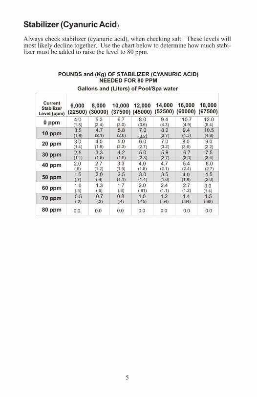
Stabilizer (Cyanuric Acid)
Always check stabilizer (cyanuric acid), when checking salt. These levels willmost likely decline together. Use the chart below to determine how much stabi-lizer must be added to raise the level to 80 ppm.
5
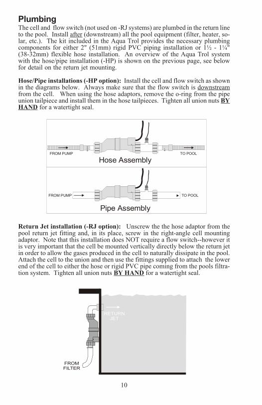
PlumbingThe cell and flow switch (not used on -RJ systems) are plumbed in the return lineto the pool. Install after (downstream) all the pool equipment (filter, heater, so-lar, etc.). The kit included in the Aqua Trol provides the necessary plumbingcomponents for either 2" (51mm) rigid PVC piping installation or 1½ - 1¼"(38-32mm) flexible hose installation. An overview of the Aqua Trol systemwith the hose/pipe installation (-HP) is shown on the previous page, see belowfor detail on the return jet mounting.
Hose/Pipe installations (-HP option): Install the cell and flow switch as shownin the diagrams below. Always make sure that the flow switch is downstreamfrom the cell. When using the hose adaptors, remove the o-ring from the pipeunion tailpiece and install them in the hose tailpieces. Tighten all union nuts BYHAND for a watertight seal.
Return Jet installation (-RJ option): Unscrew the the hose adaptor from thepool return jet fitting and, in its place, screw in the right-angle cell mountingadaptor. Note that this installation does NOT require a flow switch--however itis very important that the cell be mounted vertically directly below the return jetin order to allow the gases produced in the cell to naturally dissipate in the pool.Attach the cell to the union and then use the fittings supplied to attach the lowerend of the cell to either the hose or rigid PVC pipe coming from the pools filtra-tion system. Tighten all union nuts BY HAND for a watertight seal.
FROM PUMP
FROM PUMP
TO POOL
TO POOL
Hose Assembly
Pipe Assembly
POUNDS and (Kg) OF STABILIZER (CYANURIC ACID)NEEDED FOR 80 PPM
Gallons and (Liters) of Pool/Spa water
CurrentStabilizer
Level (ppm)
0 ppm
20 ppm
60 ppm
30 ppm
40 ppm
50 ppm
70 ppm
80 ppm
10 ppm
12,000(45000)
8,000(30000)
6,000(22500)
14,000(52500)
10,000(37500)
16,000(60000)
18,000(67500)
8.0(3.6)
5.3(2.4)
4.0(1.8)
8.0(3.6)
9.4(4.3)
6.7(3.0)
9.4(4.3)
10.7(4.9)
12.0(5.4)
7.0)(3.2
4.7(2.1)
3.5(1.6)
8.2(3.7)
5.8(2.6)
10.5(4.8)
6.0(2.7)
4.0(1.8)
3.0(1.4)
6.0(2.7)
7.0(3.2)
9.0(2.2)
5.0(2.3)
3.3(1.5)
2.5(1.1)
5.9(2.7)
4.2(1.9)
6.7(3.0)
7.5(3.4)
4.0(1.8)
2.7(1.2)
2.0(.9)
4.0(1.8)
4.7(2.1)
3.3(1.5)
5.4(2.4)
3.0(1.4)
2.0(.9)
1.5(.7)
3.0(1.4)
3.5(1.6)
2.5(1.1)
4.5(2.0)
2.0(.91)
1.3(.6)
1.0(.5)
2.4(1.1)
1.7(.8)
2.7(1.2)
1.0(.45)
0.7(.3)
0.5(.2)
1.2(.54)
0.8(.4)
1.4(.64)
1.5(.68)
0.00.00.0 0.00.0 0.0 0.0
10
FROMFILTER
RETURNJET
6
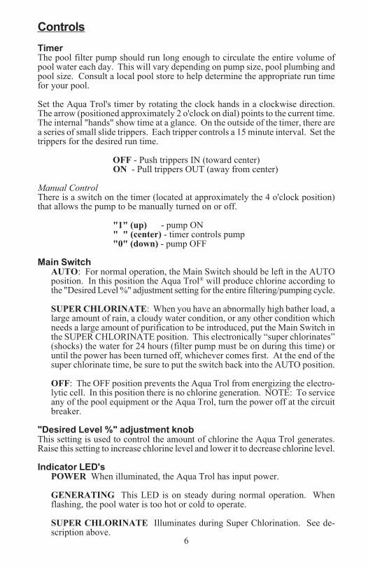
ControlsTimerThe pool filter pump should run long enough to circulate the entire volume ofpool water each day. This will vary depending on pump size, pool plumbing andpool size. Consult a local pool store to help determine the appropriate run timefor your pool.
Set the Aqua Trol's timer by rotating the clock hands in a clockwise direction.The arrow (positioned approximately 2 o'clock on dial) points to the current time.The internal "hands" show time at a glance. On the outside of the timer, there area series of small slide trippers. Each tripper controls a 15 minute interval. Set thetrippers for the desired run time.
OFF - Push trippers IN (toward center)ON - Pull trippers OUT (away from center)
Manual ControlThere is a switch on the timer (located at approximately the 4 o'clock position)that allows the pump to be manually turned on or off.
"1" (up) - pump ON" " (center) - timer controls pump"0" (down) - pump OFF
Main SwitchAUTO: For normal operation, the Main Switch should be left in the AUTOposition. In this position the Aqua Trol® will produce chlorine according tothe "Desired Level %" adjustment setting for the entire filtering/pumping cycle.
SUPER CHLORINATE: When you have an abnormally high bather load, alarge amount of rain, a cloudy water condition, or any other condition whichneeds a large amount of purification to be introduced, put the Main Switch inthe SUPER CHLORINATE position. This electronically “super chlorinates”(shocks) the water for 24 hours (filter pump must be on during this time) oruntil the power has been turned off, whichever comes first. At the end of thesuper chlorinate time, be sure to put the switch back into the AUTO position.
OFF: The OFF position prevents the Aqua Trol from energizing the electro-lytic cell. In this position there is no chlorine generation. NOTE: To serviceany of the pool equipment or the Aqua Trol, turn the power off at the circuitbreaker.
"Desired Level %" adjustment knobThis setting is used to control the amount of chlorine the Aqua Trol generates.Raise this setting to increase chlorine level and lower it to decrease chlorine level.
Indicator LED'sPOWER When illuminated, the Aqua Trol has input power.
GENERATING This LED is on steady during normal operation. Whenflashing, the pool water is too hot or cold to operate.
SUPER CHLORINATE Illuminates during Super Chlorination. See de-scription above.
9
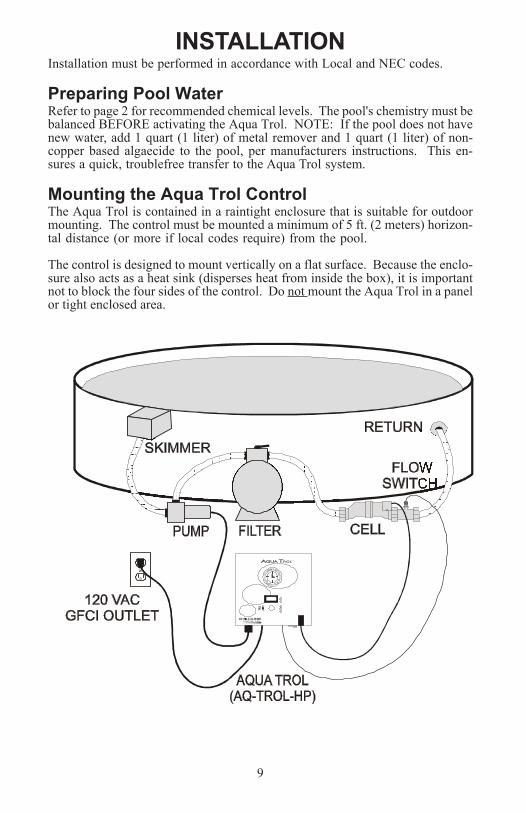
INSTALLATIONInstallation must be performed in accordance with Local and NEC codes.
Preparing Pool WaterRefer to page 2 for recommended chemical levels. The pool's chemistry must bebalanced BEFORE activating the Aqua Trol. NOTE: If the pool does not havenew water, add 1 quart (1 liter) of metal remover and 1 quart (1 liter) of non-copper based algaecide to the pool, per manufacturers instructions. This en-sures a quick, troublefree transfer to the Aqua Trol system.
Mounting the Aqua Trol ControlThe Aqua Trol is contained in a raintight enclosure that is suitable for outdoormounting. The control must be mounted a minimum of 5 ft. (2 meters) horizon-tal distance (or more if local codes require) from the pool.
The control is designed to mount vertically on a flat surface. Because the enclo-sure also acts as a heat sink (disperses heat from inside the box), it is importantnot to block the four sides of the control. Do not mount the Aqua Trol in a panelor tight enclosed area.
AQUA rolT ®
LDC
G LINEON TROLS INC.
7 8
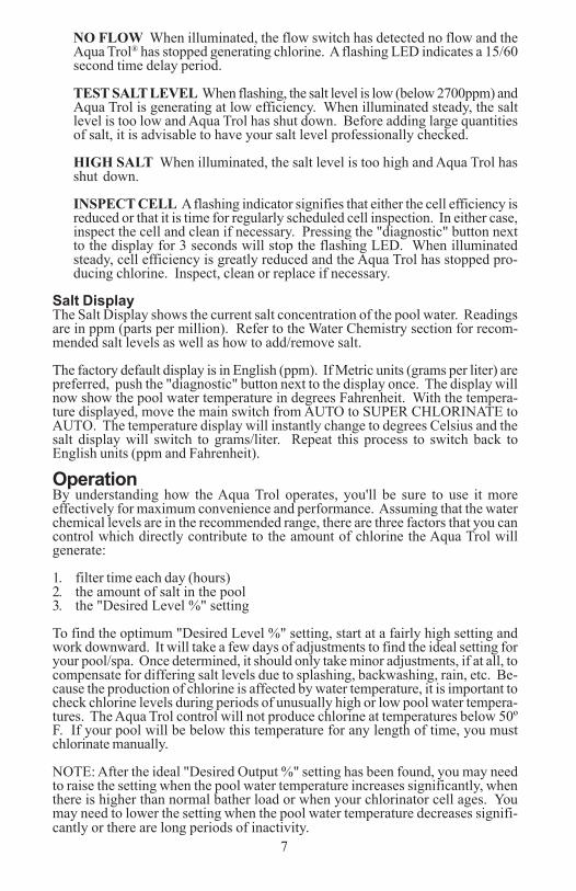
NO FLOW When illuminated, the flow switch has detected no flow and theAqua Trol® has stopped generating chlorine. A flashing LED indicates a 15/60second time delay period.
TEST SALT LEVEL When flashing, the salt level is low (below 2700ppm) andAqua Trol is generating at low efficiency. When illuminated steady, the saltlevel is too low and Aqua Trol has shut down. Before adding large quantitiesof salt, it is advisable to have your salt level professionally checked.
HIGH SALT When illuminated, the salt level is too high and Aqua Trol hasshut down.
INSPECT CELL A flashing indicator signifies that either the cell efficiency isreduced or that it is time for regularly scheduled cell inspection. In either case,inspect the cell and clean if necessary. Pressing the "diagnostic" button nextto the display for 3 seconds will stop the flashing LED. When illuminatedsteady, cell efficiency is greatly reduced and the Aqua Trol has stopped pro-ducing chlorine. Inspect, clean or replace if necessary.
Salt DisplayThe Salt Display shows the current salt concentration of the pool water. Readingsare in ppm (parts per million). Refer to the Water Chemistry section for recom-mended salt levels as well as how to add/remove salt.
The factory default display is in English (ppm). If Metric units (grams per liter) arepreferred, push the "diagnostic" button next to the display once. The display willnow show the pool water temperature in degrees Fahrenheit. With the tempera-ture displayed, move the main switch from AUTO to SUPER CHLORINATE toAUTO. The temperature display will instantly change to degrees Celsius and thesalt display will switch to grams/liter. Repeat this process to switch back toEnglish units (ppm and Fahrenheit).
OperationBy understanding how the Aqua Trol operates, you'll be sure to use it moreeffectively for maximum convenience and performance. Assuming that the waterchemical levels are in the recommended range, there are three factors that you cancontrol which directly contribute to the amount of chlorine the Aqua Trol willgenerate:
1. filter time each day (hours)2. the amount of salt in the pool3. the "Desired Level %" setting
To find the optimum "Desired Level %" setting, start at a fairly high setting andwork downward. It will take a few days of adjustments to find the ideal setting foryour pool/spa. Once determined, it should only take minor adjustments, if at all, tocompensate for differing salt levels due to splashing, backwashing, rain, etc. Be-cause the production of chlorine is affected by water temperature, it is important tocheck chlorine levels during periods of unusually high or low pool water tempera-tures. The Aqua Trol control will not produce chlorine at temperatures below 50ºF. If your pool will be below this temperature for any length of time, you mustchlorinate manually.
NOTE: After the ideal "Desired Output %" setting has been found, you may needto raise the setting when the pool water temperature increases significantly, whenthere is higher than normal bather load or when your chlorinator cell ages. Youmay need to lower the setting when the pool water temperature decreases signifi-cantly or there are long periods of inactivity.
Maintaining the Aqua Trol® SystemTo maintain maximum performance, it is recommended that you open and visuallyinspect the cell every 3 months or after cleaning your filter. The Aqua Trol willremind you to do this by flashing the "Inspect Cell" LED after approximately 500hours of operation. After you inspect the cell (and clean, if necessary) press thesmall "diagnostic" button next to the display for 3 seconds to stop the flashing"Inspect Cell" LED and start the timer for the next 500 hour inspection period.
The Aqua Trol electrolytic cell has a self cleaning feature incorporated into theelectronic control’s logic. In most cases this self cleaning action will keep thecell working at optimum efficiency. In areas where water is hard (high mineralcontent) and in pools where the water chemistry has been allowed to get "out ofbalance", the cell may require periodic cleaning. The "Inspect Cell" LED willindicate if cell efficiency is decreased and servicing is necessary. If the "InspectCell" LED remains on after a thorough cleaning, the cell may be worn and re-quire replacement.
Servicing and Cleaning the Aqua Trol cellTurn off power to the Aqua Trol before removing the electrolytic cell. Onceremoved, look inside the cell and inspect for scale formation (light colored crustyor flaky deposits) on the plates and for any debris which has passed through thefilter and caught on the plates. If no deposits are visible, reinstall. If deposits areseen, use a high pressure garden hose and try to flush the scale off. If this is notsuccessful, use a plastic or wood tool (do not use metal as this will scratch thecoating off the plates) and scrape deposits off of the plates. Note that a buildupon the cell indicates that there is an unusually high calcium level in the pool (oldpool water is usually the cause). If this is not corrected, you can expect to have toperiodically clean the cell. The simplest way to avoid this is to bring the poolchemistry to the recommended levels as specified.
Mild Acid Washing: Use only in severe cases where flushing and scraping willnot remove the majority of deposits. To acid wash, turn off power to Aqua Trol.Remove cell from piping. In a clean plastic container, mix a 4:1 solution of waterto muriatic acid (one gallon of water to one quart of muriatic acid). ALWAYSPOUR ACID INTO WATER - NEVER POUR WATER INTO ACID. Be sure towear rubber gloves and appropriate eye protection. The level of the solution inthe container should just reach the top of the cell so that the wire harness com-partment is NOT submerged. It may be helpful to coil the wiring before immers-ing the cell. The cell should soak for a few minutes and then rinse with a highpressure garden hose. If any deposits are still visible, repeat soaking and rinsing.Replace cell and inspect again periodically.
WinterizingThe Aqua Trol electrolytic cell and flow detection switch will be damaged byfreezing water just as your pool plumbing would. In areas of the country whichexperience severe or extended periods of freezing temperatures, be sure to drainall water from the pump, filter, and supply and return lines before any freezingconditions occur. The electronic control is capable of withstanding any winterweather and should not be removed.
Spring Start-upDO NOT turn the Aqua Trol on, until the pool water chemistry has been broughtto the proper levels. This information can be found on page 2.
7 8
NO FLOW When illuminated, the flow switch has detected no flow and theAqua Trol® has stopped generating chlorine. A flashing LED indicates a 15/60second time delay period.
TEST SALT LEVEL When flashing, the salt level is low (below 2700ppm) andAqua Trol is generating at low efficiency. When illuminated steady, the saltlevel is too low and Aqua Trol has shut down. Before adding large quantitiesof salt, it is advisable to have your salt level professionally checked.
HIGH SALT When illuminated, the salt level is too high and Aqua Trol hasshut down.
INSPECT CELL A flashing indicator signifies that either the cell efficiency isreduced or that it is time for regularly scheduled cell inspection. In either case,inspect the cell and clean if necessary. Pressing the "diagnostic" button nextto the display for 3 seconds will stop the flashing LED. When illuminatedsteady, cell efficiency is greatly reduced and the Aqua Trol has stopped pro-ducing chlorine. Inspect, clean or replace if necessary.
Salt DisplayThe Salt Display shows the current salt concentration of the pool water. Readingsare in ppm (parts per million). Refer to the Water Chemistry section for recom-mended salt levels as well as how to add/remove salt.
The factory default display is in English (ppm). If Metric units (grams per liter) arepreferred, push the "diagnostic" button next to the display once. The display willnow show the pool water temperature in degrees Fahrenheit. With the tempera-ture displayed, move the main switch from AUTO to SUPER CHLORINATE toAUTO. The temperature display will instantly change to degrees Celsius and thesalt display will switch to grams/liter. Repeat this process to switch back toEnglish units (ppm and Fahrenheit).
OperationBy understanding how the Aqua Trol operates, you'll be sure to use it moreeffectively for maximum convenience and performance. Assuming that the waterchemical levels are in the recommended range, there are three factors that you cancontrol which directly contribute to the amount of chlorine the Aqua Trol willgenerate:
1. filter time each day (hours)2. the amount of salt in the pool3. the "Desired Level %" setting
To find the optimum "Desired Level %" setting, start at a fairly high setting andwork downward. It will take a few days of adjustments to find the ideal setting foryour pool/spa. Once determined, it should only take minor adjustments, if at all, tocompensate for differing salt levels due to splashing, backwashing, rain, etc. Be-cause the production of chlorine is affected by water temperature, it is important tocheck chlorine levels during periods of unusually high or low pool water tempera-tures. The Aqua Trol control will not produce chlorine at temperatures below 50ºF. If your pool will be below this temperature for any length of time, you mustchlorinate manually.
NOTE: After the ideal "Desired Output %" setting has been found, you may needto raise the setting when the pool water temperature increases significantly, whenthere is higher than normal bather load or when your chlorinator cell ages. Youmay need to lower the setting when the pool water temperature decreases signifi-cantly or there are long periods of inactivity.
Maintaining the Aqua Trol® SystemTo maintain maximum performance, it is recommended that you open and visuallyinspect the cell every 3 months or after cleaning your filter. The Aqua Trol willremind you to do this by flashing the "Inspect Cell" LED after approximately 500hours of operation. After you inspect the cell (and clean, if necessary) press thesmall "diagnostic" button next to the display for 3 seconds to stop the flashing"Inspect Cell" LED and start the timer for the next 500 hour inspection period.
The Aqua Trol electrolytic cell has a self cleaning feature incorporated into theelectronic control’s logic. In most cases this self cleaning action will keep thecell working at optimum efficiency. In areas where water is hard (high mineralcontent) and in pools where the water chemistry has been allowed to get "out ofbalance", the cell may require periodic cleaning. The "Inspect Cell" LED willindicate if cell efficiency is decreased and servicing is necessary. If the "InspectCell" LED remains on after a thorough cleaning, the cell may be worn and re-quire replacement.
Servicing and Cleaning the Aqua Trol cellTurn off power to the Aqua Trol before removing the electrolytic cell. Onceremoved, look inside the cell and inspect for scale formation (light colored crustyor flaky deposits) on the plates and for any debris which has passed through thefilter and caught on the plates. If no deposits are visible, reinstall. If deposits areseen, use a high pressure garden hose and try to flush the scale off. If this is notsuccessful, use a plastic or wood tool (do not use metal as this will scratch thecoating off the plates) and scrape deposits off of the plates. Note that a buildupon the cell indicates that there is an unusually high calcium level in the pool (oldpool water is usually the cause). If this is not corrected, you can expect to have toperiodically clean the cell. The simplest way to avoid this is to bring the poolchemistry to the recommended levels as specified.
Mild Acid Washing: Use only in severe cases where flushing and scraping willnot remove the majority of deposits. To acid wash, turn off power to Aqua Trol.Remove cell from piping. In a clean plastic container, mix a 4:1 solution of waterto muriatic acid (one gallon of water to one quart of muriatic acid). ALWAYSPOUR ACID INTO WATER - NEVER POUR WATER INTO ACID. Be sure towear rubber gloves and appropriate eye protection. The level of the solution inthe container should just reach the top of the cell so that the wire harness com-partment is NOT submerged. It may be helpful to coil the wiring before immers-ing the cell. The cell should soak for a few minutes and then rinse with a highpressure garden hose. If any deposits are still visible, repeat soaking and rinsing.Replace cell and inspect again periodically.
WinterizingThe Aqua Trol electrolytic cell and flow detection switch will be damaged byfreezing water just as your pool plumbing would. In areas of the country whichexperience severe or extended periods of freezing temperatures, be sure to drainall water from the pump, filter, and supply and return lines before any freezingconditions occur. The electronic control is capable of withstanding any winterweather and should not be removed.
Spring Start-upDO NOT turn the Aqua Trol on, until the pool water chemistry has been broughtto the proper levels. This information can be found on page 2.
6
ControlsTimerThe pool filter pump should run long enough to circulate the entire volume ofpool water each day. This will vary depending on pump size, pool plumbing andpool size. Consult a local pool store to help determine the appropriate run timefor your pool.
Set the Aqua Trol's timer by rotating the clock hands in a clockwise direction.The arrow (positioned approximately 2 o'clock on dial) points to the current time.The internal "hands" show time at a glance. On the outside of the timer, there area series of small slide trippers. Each tripper controls a 15 minute interval. Set thetrippers for the desired run time.
OFF - Push trippers IN (toward center)ON - Pull trippers OUT (away from center)
Manual ControlThere is a switch on the timer (located at approximately the 4 o'clock position)that allows the pump to be manually turned on or off.
"1" (up) - pump ON" " (center) - timer controls pump"0" (down) - pump OFF
Main SwitchAUTO: For normal operation, the Main Switch should be left in the AUTOposition. In this position the Aqua Trol® will produce chlorine according tothe "Desired Level %" adjustment setting for the entire filtering/pumping cycle.
SUPER CHLORINATE: When you have an abnormally high bather load, alarge amount of rain, a cloudy water condition, or any other condition whichneeds a large amount of purification to be introduced, put the Main Switch inthe SUPER CHLORINATE position. This electronically “super chlorinates”(shocks) the water for 24 hours (filter pump must be on during this time) oruntil the power has been turned off, whichever comes first. At the end of thesuper chlorinate time, be sure to put the switch back into the AUTO position.
OFF: The OFF position prevents the Aqua Trol from energizing the electro-lytic cell. In this position there is no chlorine generation. NOTE: To serviceany of the pool equipment or the Aqua Trol, turn the power off at the circuitbreaker.
"Desired Level %" adjustment knobThis setting is used to control the amount of chlorine the Aqua Trol generates.Raise this setting to increase chlorine level and lower it to decrease chlorine level.
Indicator LED'sPOWER When illuminated, the Aqua Trol has input power.
GENERATING This LED is on steady during normal operation. Whenflashing, the pool water is too hot or cold to operate.
SUPER CHLORINATE Illuminates during Super Chlorination. See de-scription above.
9
INSTALLATIONInstallation must be performed in accordance with Local and NEC codes.
Preparing Pool WaterRefer to page 2 for recommended chemical levels. The pool's chemistry must bebalanced BEFORE activating the Aqua Trol. NOTE: If the pool does not havenew water, add 1 quart (1 liter) of metal remover and 1 quart (1 liter) of non-copper based algaecide to the pool, per manufacturers instructions. This en-sures a quick, troublefree transfer to the Aqua Trol system.
Mounting the Aqua Trol ControlThe Aqua Trol is contained in a raintight enclosure that is suitable for outdoormounting. The control must be mounted a minimum of 5 ft. (2 meters) horizon-tal distance (or more if local codes require) from the pool.
The control is designed to mount vertically on a flat surface. Because the enclo-sure also acts as a heat sink (disperses heat from inside the box), it is importantnot to block the four sides of the control. Do not mount the Aqua Trol in a panelor tight enclosed area.
AQUA rolT ®
LDC
G LINEON TROLS INC.
Stabilizer (Cyanuric Acid)
Always check stabilizer (cyanuric acid), when checking salt. These levels willmost likely decline together. Use the chart below to determine how much stabi-lizer must be added to raise the level to 80 ppm.
5
PlumbingThe cell and flow switch (not used on -RJ systems) are plumbed in the return lineto the pool. Install after (downstream) all the pool equipment (filter, heater, so-lar, etc.). The kit included in the Aqua Trol provides the necessary plumbingcomponents for either 2" (51mm) rigid PVC piping installation or 1½ - 1¼"(38-32mm) flexible hose installation. An overview of the Aqua Trol systemwith the hose/pipe installation (-HP) is shown on the previous page, see belowfor detail on the return jet mounting.
Hose/Pipe installations (-HP option): Install the cell and flow switch as shownin the diagrams below. Always make sure that the flow switch is downstreamfrom the cell. When using the hose adaptors, remove the o-ring from the pipeunion tailpiece and install them in the hose tailpieces. Tighten all union nuts BYHAND for a watertight seal.
Return Jet installation (-RJ option): Unscrew the the hose adaptor from thepool return jet fitting and, in its place, screw in the right-angle cell mountingadaptor. Note that this installation does NOT require a flow switch--however itis very important that the cell be mounted vertically directly below the return jetin order to allow the gases produced in the cell to naturally dissipate in the pool.Attach the cell to the union and then use the fittings supplied to attach the lowerend of the cell to either the hose or rigid PVC pipe coming from the pools filtra-tion system. Tighten all union nuts BY HAND for a watertight seal.
FROM PUMP
FROM PUMP
TO POOL
TO POOL
Hose Assembly
Pipe Assembly
POUNDS and (Kg) OF STABILIZER (CYANURIC ACID)NEEDED FOR 80 PPM
Gallons and (Liters) of Pool/Spa water
CurrentStabilizer
Level (ppm)
0 ppm
20 ppm
60 ppm
30 ppm
40 ppm
50 ppm
70 ppm
80 ppm
10 ppm
12,000(45000)
8,000(30000)
6,000(22500)
14,000(52500)
10,000(37500)
16,000(60000)
18,000(67500)
8.0(3.6)
5.3(2.4)
4.0(1.8)
8.0(3.6)
9.4(4.3)
6.7(3.0)
9.4(4.3)
10.7(4.9)
12.0(5.4)
7.0)(3.2
4.7(2.1)
3.5(1.6)
8.2(3.7)
5.8(2.6)
10.5(4.8)
6.0(2.7)
4.0(1.8)
3.0(1.4)
6.0(2.7)
7.0(3.2)
9.0(2.2)
5.0(2.3)
3.3(1.5)
2.5(1.1)
5.9(2.7)
4.2(1.9)
6.7(3.0)
7.5(3.4)
4.0(1.8)
2.7(1.2)
2.0(.9)
4.0(1.8)
4.7(2.1)
3.3(1.5)
5.4(2.4)
3.0(1.4)
2.0(.9)
1.5(.7)
3.0(1.4)
3.5(1.6)
2.5(1.1)
4.5(2.0)
2.0(.91)
1.3(.6)
1.0(.5)
2.4(1.1)
1.7(.8)
2.7(1.2)
1.0(.45)
0.7(.3)
0.5(.2)
1.2(.54)
0.8(.4)
1.4(.64)
1.5(.68)
0.00.00.0 0.00.0 0.0 0.0
10
FROMFILTER
RETURNJET
4
Gallons and (Liters) of Pool/Spa water
12,000 14,000 16,000 18,000Current salt
level(45000) (52,500) (60,000) (67,500)ppm
0 320 (145)
373 (170)
427 (194)
480 (218)
200 300 (136)
350 (159)
400 (182)
450 (205)
400 280 (127)
327 (148)
373 (170)
420 (191)
600 260 (118)
303 (138)
347 (158)
390 (177)
800 240 (109)
280 (127)
320 (145)
360 (164)
1000 220 (100)
257 (117)
293 (133)
330 (150)
1200 200 (91)
233 (106)
267 (121)
300 (136)
1400 180 (82)
210 (95)
240 (109) (123)
1600 160 (73)
187 (85)
213 (97)
240 (109)
1800 140 (64)
163 (74)
187 (85)
210 (95)
2000 120
100
80
60
20
40
(55)
(45)
(36)
(27)
(9)
(18)
140
117
23
47
(64)
(53)
(11)
(21)
160
133
27
53
(73)
(61)
(12)
(24)
180
150
30
60
(82)
(68)
(14)
(27)
(32)80 (36)
90 (41)
93 (42)
107 (48)
120 (55)
2200
3000
2800
2400
3200 Ideal Ideal Ideal Ideal
2600
3400 OKOKOK OKOK OK OK
POUNDS and (Kg) OF SALT NEEDED FOR 3200 PPM
3600+ Dilute Dilute Dilute Dilute
10,000 8,000 6,000(37,500)
213 160 267 (97)(73) (121)
200 150 250 (91)(69) (114)
187 140 233 (85)(64) (106)
173 130 217 (79)(59) (98)
160 120 200 (73)(55) (91)
147 110 183 (67)(51) (83)
133 100 167 (61)(46 (76)
120 90 150 (55)(41) (68)
107 80 133 (48)(36) (61)93 70 117 (42)(32) (53)
80 60 100
67 50 83
53 40 67
40 30 50
13 10 17
27 20 33
(36)(27) (45)
(30)(23) (38)
(24)(18) (30)
(18)(14) (23)
(6)(4) (8)
(12)(9) (15)
IdealIdeal Ideal
DiluteDilute Dilute
(30,000)(22,500)
11
Wiring
Power must be shut off at the circuit breaker before performing any wiring. Besure to follow Local and NEC/CEC electrical codes. The Aqua Trol has beendesigned to easily wire into typical above ground pool systems. To provide safeoperation, the Aqua Trol must be properly grounded and bonded.
Input PowerModels with the standard 120 VAC line cord should be plugged into a GFCIreceptacle. Twist lock models should be plugged into a twist lock receptaclewired to a GFCI circuit breaker. For Canadian installations: Connect to a cir-cuit protected by a Class-A ground fault interruptor. See diagram below.
SUBPANEL
SUBPANEL
GROUND
GROUND
NEUTRAL
NEUTRAL
GFCIOUTLET
TWIST-LOCKOUTLET (L520)
TWIST-LOCKPLUGS (L520)
BONDINGLOOP
BONDINGLOOP
PUMP
PUMP
AQUA TROL(AQ-TROL-XX)
AQUA TROL(AQ-TROL-XX-TL)
GFCI CIRCUITBREAKER
AQUA rolT
LDC
G LINEON TROLS INC.
AQUA rolT ®
LDC
G LINEON TROLS INC .

3
Salt LevelUse the chart on page 4 to determine how much salt in pounds (or Kgs) needs tobe added to reach the recommended levels. Use the equations below (measure-ments are in feet/gallons and meters/liters) if pool size is unknown.
The ideal salt level is between 2700-3400 ppm (parts per million) with 3200 ppmbeing optimal. If the level is low, determine the number of gallons in the pooland add salt according to the chart on page 4. A low salt level will reduce theefficiency of the Aqua Trol® and result in low chlorine production. A high saltlevel can cause the Aqua Trol to shutdown and may begin to give a salty taste toyour pool (generally, the salt will begin to be tasted at a level of about 3500-4000ppm). The salt in your pool is constantly recycled and the loss of salt throughoutthe swimming season should be small. This loss is due primarily to the additionof water because of splashing, backwashing or draining (because of rain). Salt isnot lost due to evaporation.
Type of Salt to UseIt is important to use only sodium chloride (NaCl) that is 99% pure. This iscommon food quality or water softener salt available in 40-80 lb. bags at your localGoldline dealer. It is also acceptable to use water conditioning salt pellets, how-ever, it will take longer for them to dissolve. Do not use rock salt, salt with morethan 1% yellow prussiate of soda, salt with more than 1% of anti-caking additives,or iodized salt.
How to Add or Remove SaltTurn the filter pump on and add the salt directly into the pool. Brush the salt tospeed up the dissolving process--to not allow the salt to sit in a pile on the bottomof the pool. Run the filter pump for 24 hours with the suction coming from themain drain (use the pool vacuum if there is not main drain) to allow the salt toevenly disperse throughout the pool. The salt display may take 24 hours to re-spond to the change in salt concentration.
The only way to lower the salt concentration is to partially drain the pool and refillwith fresh water.
12
Gallons Liters(pool size in feet) (pool size in meters)
Rectangular
Round
Oval
Diameter x Diameter x Average Depth x 5.9
Length x Width x Average Depth x 6.7
Length x Width x Average Depth x 7.5
Diameter x Diameter x Average Depth x 785
Length x Width x Average Depth x 893
Length x Width x Average Depth x 1000
BondingA lug used for bonding is attached to the bottom of the Aqua Trol enclosure.Connect to the pool bonding system using minimum 8AWG copper wire if re-quired by code.
Pump OutputThe Aqua Trol's filter pump output is rated at 120 VAC, 15 A max. Check theelectrical rating marked on the pump motor. Connecting a pump with a higheramperage rating may result in permanent damage to the Aqua Trol. The 120VAC standard or twist lock pump receptacle is located outside, on the bottom ofthe enclosure.
Electrolytic Cell and Flow SwitchThe cell and flow switch plug into connectors on the Aqua Trol electronics unit.Note that return jet units (-RJ option) will NOT have a flow switch. See diagrambelow.
Phone jackto flow switch
Bonding lug topool bonding system
OUTPUT POWER120 VAC receptacle
to pool pump
INPUT POWER120 VAC linecord
to GFCI receptacle/breaker
Cutout forcell cable
Water ChemistryAs with any pool, it is important that you maintain chemical makeup of the poolwater. The table on page 2 summarizes the levels that are recommended by theNational Spa and Pool Institute (NSPI). The only special requirement for the AquaTrol is the salt level and stabilizer. It is important to maintain these levels in orderto prevent corrosion or scaling and to ensure maximum enjoyment of the pool.Test your water periodically. Your local pool store can provide you with thechemicals and procedures to adjust the water chemistry. Be sure to tell the poolstore that you are using an Aqua Trol chlorine generator.
Saturation indexThe saturation index (Si) relates to the calcium and alkalinity in the water and isan indicator of the pool water "balance". Your water is properly balanced if theSi is 0 ±.2. If the Si is below -0.2, the water is corrosive and plaster pool wallswill be dissolved into the water. If the Si is above +0.2, scaling and staining willoccur. Use the equation and chart below to determine the saturation index.
2
ºC ºF Ti CalcuimHardness Ci Total
Alkalinity Ai
53
60
66
76
84
94
103
12
16
19
24
29
34
39
.3
.4
.5
.6
.7
.8
.9How to use: Measure pool pH, temperature, calcium hardness,and total alkalinity. Use the chart above to determine Ti, Ci,andAi from your measurements. Insert values of pH, Ti, Ci and Aiinto the above equation. If Si equals .2 or more, scaling and staining may occur. If Si equals -.2 or less corrosion or irritationmay occur.
Si = pH + Ti + Ci + Ai - 12.1
-.2 0 .2CORROSIVE SCALING
75 75100 100125 125150 150200 200250 250300 300400 400600 600800 800
1.5 1.91.6 2.01.7 2.11.8 2.21.9 2.32.0 2.42.1 2.52.2 2.62.4 2.82.5 2.9
OK
13
Troubleshooting
Diagnostic Displays
Sequential pushes of the small "diagnostic" button next to the LCD display willcause the Aqua Trol to display the following information:
1. Pool temperature (xx degrees Fahrenheit or Celsius)2. Cell voltage (typically 22.0 to 26.0 volts when chlorine is being generated,
otherwise 30-35V)3. Cell current (typically 2.50 to 4.00 amps when chlorine is being generated,
otherwise 0 amps)4. Desired Output % ("0P" -- "100P" depending on knob position )5. Instant salinity ( -xxxx ppm or -x.xx grams/Liter)6. Product name sent to the display ("AL-6" signifies "Aqua Trol" (STD), ("AL-
7" signifies "Aqua Trol Return-Jet")7. Software revision level (r1.xx)
On the 8th push of the button the display will revert back to the default saltdisplay. Also, if the button is not pushed for 30 seconds, the display will revertback to the standard salt display.
Common Problems and Solutions
1. "Power" LED not onCheck to make sure 120VAC input power is connected to the Aqua Trol control.Verify input voltage with a voltmeter. If there is input power, the fuse may haveblown. The Aqua Trol is protected by a 20 amp mini ATO fuse located on thecircuit board above the cell connector.
2. Filter pump not runningCheck that the time clock manual switch is in the "auto" (center) position or inthe "on" (top) position. If in "auto", then check that the time is correct (check am/pm by using the 24 hour indicator located near the 2 o'clock position) and that thetrippers are in the "out" position.
3. "Generating" LED not onThe Aqua Trol only generates chlorine when the filter pump is running, the mainswitch is in the "AUTO" or "SUPER CHLORINATE" position, and none of thered fault LEDs are illuminated.
4. "Generating" LED flashingThe temperature of the pool water is too high or low to operate. You can overridethis by switching the main switch to SUPER CHLORINATE. The Aqua Trol willrun at maximum output for the remainder of the current pump cycle or 24 hours,whichever comes first.
5. "No Flow" LED illuminatedThe Aqua Trol® has sensed a no flow condition and has stopped generatingchlorine. Check that the flow switch is plugged into the connector on the bottom
1
OPERATIONThe Aqua Trol® is an automatic chlorine generation system with a built-in filterpump timer designed specifically for above ground pools. The operation re-quires a low concentration of salt (sodium chloride) in the pool water at levelslow enough that it normally will not be tasted. The Aqua Trol automaticallysanitizes your pool by converting the salt into free chlorine which kills bacteriaand algae in the pool through a process called electrolysis. Because chlorine willrevert back to sodium chloride after killing the bacteria, these reactions will con-tinuously recycle virtually eliminating the need to add sanitizing chemicals toyour pool. The only time you may need to add more salt to the pool is whenwater is replenished due to backwashing, draining, or splashing (not evapora-tion).
The Aqua Trol incorporates a built in timer to control the pool filter. This timerinsures that the proper daily filtration and sanitization occurs. The Aqua Trol isdesigned to handle the purification needs of the average residential above groundswimming pool of up to 18,000 gallons (67,500 liters). The actual amount ofchlorination required to properly sanitize a pool varies depending upon batherload, rainfall, temperature, and the pool's cleanliness.
The Aqua Trol is available with several different options to allow for easy instal-lation on a wide variety of above ground pools. The cell may be connected with1½" - 1¼" flexible hose or to 2" rigid PVC pipe when the -HP option is ordered,or the cell may be mounted directly to the pool return jet when the -RJ version isordered. Similarly, the electrical connections may be made via 120V/15A "straightblade" linecord and receptacle (standard Aqua Trol version, no option designa-tion) or may be made via a 120V/20A "twist lock" linecord and receptacle whenthe -TL version is ordered.
AQ-Trol-HP "Straight blade" 120V/15A linecord/receptacle; 2" (51mm)rigid PVC piping or 1½ - 1¼" (38-32mm) flexible hose
AQ-Trol-HP-TL "Twist lock" 120/20A linecord/receptacle; 2" (51mm) rigidPVC piping or 1½ - 1¼" (38-32mm)flexible hose
AQ-Trol-RJ "Straight blade" 120V/15A linecord/receptacle; adapters forreturn jet mounting
AQ-Trol-RJ-TL "Twist lock" 120V/20A linecord/receptacle; adapters for re-turn jet mounting
NOTE: Before installing this product as part of a saline water purification systemin an above-ground pool with an immediately adjacent natural stone patio/deck-ing, a qualified stone installation specialist should be consulted regarding theappropriate type, installation, sealant (if any) and maintenance of stone usedaround a saline pool with electronic chlorine generator in your particular locationand circumstances.
NOTE: The use of dry acid (sodium bisulfate) to adjust pool pH is discouragedespecially in arid regions where pool water is subject to excessive evaporation andis not commonly diluted with fresh water. Dry acid can cause a buildup of by-products that can damage your chlorinator cell.
14
of the control unit and that the wire is not cut or damaged. Make sure you have atleast 12" of straight pipe before the flow switch. If there is adequate flow and theLED is still on, check that the arrows on the flow switch (on top of hex) are pointingin the direction of flow.
6. "Test Salt Level" LED illuminated or flashingTake a sample of your pool water to your local Authorized Aqua Rite Dealer andhave the salt level tested. No salt test is completely accurate and the test resultsmay vary from the salt level on the Aqua Trol display. If salt level is low, add saltaccording to chart on page 4.
7. "High Salt" LED illuminatedCheck salt level in pool/spa. If salt level is too high, lower salt level by drainingsome of the pool water out of the pool and replace with fresh water. Continueuntil the salt concentration is at recommended levels.
8. "Inspect Cell" LED flashingInspect and clean cell according to directions on page 8. When done, press the"diagnostic" button for 3 seconds to stop the "Inspect Cell" LED flashing.
9. "Inspect Cell" LED illuminatedRemove and inspect the cell for scale. If the cell is scaled, follow the directionson page 8 for cell cleaning. If the pool has the proper amount of salt and the"Inspect Cell" LED is still illuminated, the cell may be worn and need replace-ment.
10. Possible causes of little or no free chlorine residual- Aqua Trol switch in OFF position.- Desired Level % adjustment setting is too low.- Low stabilizer (Cyanuric Acid).- Filter pump switched off or filter pump time too short (8 hours for average size
pools, more for large pools)- Salt level too low (below 2500 ppm, Low Salt LED on).- Salt level too high (High Salt LED on).- Very warm pools increase chlorine demand--increase Desired Level % or filter
run time.- Cold water (below 50F) causes Aqua Trol to stop generating (Generating LED
flashing).- Excessive scaling on cell.- High level of Nitrogen in pool water.- "Yellow Out" or similar treatment recently used. Some yellow algae treatments
will use chlorine at a very high rate and deplete the residual free chlorine.Manually shock the pool if indicated in the directions on the algae treatment. Itstill may be a matter of days before the pool returns to "normal" and chlorinetests will show the desired 1-3ppm free chlorine reading.
11. "-Pcb-" displayed and all 4 red/yellow LEDs are illuminated.A possible Printed Circuit Board fault has been detected.

Table of Contents
OPERATIONOPERATIONOPERATIONOPERATIONOPERATIONThe Aqua TrolThe Aqua TrolThe Aqua TrolThe Aqua TrolThe Aqua Trol®®®®®...........................................................................................1
Water Chemistry....Water Chemistry....Water Chemistry....Water Chemistry....Water Chemistry.....................................................................1
Controls . . . . . . . . . . . . . . . . . . . . . . . . . . . . . . . . . . . . . . . . . . . . . . . . . . . . . . . . . . . . . . . . . . . .Controls . . . . . . . . . . . . . . . . . . . . . . . . . . . . . . . . . . . . . . . . . . . . . . . . . . . . . . . . . . . . . . . . . . . .Controls . . . . . . . . . . . . . . . . . . . . . . . . . . . . . . . . . . . . . . . . . . . . . . . . . . . . . . . . . . . . . . . . . . . .Controls . . . . . . . . . . . . . . . . . . . . . . . . . . . . . . . . . . . . . . . . . . . . . . . . . . . . . . . . . . . . . . . . . . . .Controls . . . . . . . . . . . . . . . . . . . . . . . . . . . . . . . . . . . . . . . . . . . . . . . . . . . . . . . . . . . . . . . . . . . .6
Maintenance.. . . . . . . . . . . . . . . . . . . . . . . . . . . . . . . . . . . . . . . . . . . . . . . . . . . . . . .Maintenance.. . . . . . . . . . . . . . . . . . . . . . . . . . . . . . . . . . . . . . . . . . . . . . . . . . . . . . .Maintenance.. . . . . . . . . . . . . . . . . . . . . . . . . . . . . . . . . . . . . . . . . . . . . . . . . . . . . . .Maintenance.. . . . . . . . . . . . . . . . . . . . . . . . . . . . . . . . . . . . . . . . . . . . . . . . . . . . . . .Maintenance.. . . . . . . . . . . . . . . . . . . . . . . . . . . . . . . . . . . . . . . . . . . . . . . . . . . . . . . . . . . . . . . .8.
INSTALLATIONINSTALLATIONINSTALLATIONINSTALLATIONINSTALLATIONMounting. . . . . . . . . . . . . . . . . . . . . . . . . . . . . . . . . . . . . . . . . . . . . . . . . . . . . . . . . . . . . . . . . . . .Mounting. . . . . . . . . . . . . . . . . . . . . . . . . . . . . . . . . . . . . . . . . . . . . . . . . . . . . . . . . . . . . . . . . . . .Mounting. . . . . . . . . . . . . . . . . . . . . . . . . . . . . . . . . . . . . . . . . . . . . . . . . . . . . . . . . . . . . . . . . . . .Mounting. . . . . . . . . . . . . . . . . . . . . . . . . . . . . . . . . . . . . . . . . . . . . . . . . . . . . . . . . . . . . . . . . . . .Mounting. . . . . . . . . . . . . . . . . . . . . . . . . . . . . . . . . . . . . . . . . . . . . . . . . . . . . . . . . . . . . . . . . . . .9
Plumbing. . . . . . . . . . . . . . . . . . . . . . . . . . . . . . . . . . . . . . . . . . . . . . . . . . . . . . . . . . . . . .Plumbing. . . . . . . . . . . . . . . . . . . . . . . . . . . . . . . . . . . . . . . . . . . . . . . . . . . . . . . . . . . . . .Plumbing. . . . . . . . . . . . . . . . . . . . . . . . . . . . . . . . . . . . . . . . . . . . . . . . . . . . . . . . . . . . . .Plumbing. . . . . . . . . . . . . . . . . . . . . . . . . . . . . . . . . . . . . . . . . . . . . . . . . . . . . . . . . . . . . .Plumbing. . . . . . . . . . . . . . . . . . . . . . . . . . . . . . . . . . . . . . . . . . . . . . . . . . . . . . . . . . . . . . . . . . . . .10
Wiring. . . . . . . . . . . . . . . . . . . . . . . . . . . . . . . . . . . . . . . . . . . . . . . . . . . . . . . . . . . . . .Wiring. . . . . . . . . . . . . . . . . . . . . . . . . . . . . . . . . . . . . . . . . . . . . . . . . . . . . . . . . . . . . .Wiring. . . . . . . . . . . . . . . . . . . . . . . . . . . . . . . . . . . . . . . . . . . . . . . . . . . . . . . . . . . . . .Wiring. . . . . . . . . . . . . . . . . . . . . . . . . . . . . . . . . . . . . . . . . . . . . . . . . . . . . . . . . . . . . .Wiring. . . . . . . . . . . . . . . . . . . . . . . . . . . . . . . . . . . . . . . . . . . . . . . . . . . . . . . . . . . . . . . . . . . . . . . . .11
TROUBLESHOOTINGTROUBLESHOOTINGTROUBLESHOOTINGTROUBLESHOOTINGTROUBLESHOOTINGTroubleshooting.... . . . . . . . . . . . . . . . . . . . . . . . . . . . . . . . .Troubleshooting.... . . . . . . . . . . . . . . . . . . . . . . . . . . . . . . . .Troubleshooting.... . . . . . . . . . . . . . . . . . . . . . . . . . . . . . . . .Troubleshooting.... . . . . . . . . . . . . . . . . . . . . . . . . . . . . . . . .Troubleshooting.... . . . . . . . . . . . . . . . . . . . . . . . . . . . . . . . . .........................13
WARRANTYWARRANTYWARRANTYWARRANTYWARRANTYWarranty.... . . . . . . . . . . . . . . . . . . . . . . . . . . . . . . . . . . . . . . .Warranty.... . . . . . . . . . . . . . . . . . . . . . . . . . . . . . . . . . . . . . . .Warranty.... . . . . . . . . . . . . . . . . . . . . . . . . . . . . . . . . . . . . . . .Warranty.... . . . . . . . . . . . . . . . . . . . . . . . . . . . . . . . . . . . . . . .Warranty.... . . . . . . . . . . . . . . . . . . . . . . . . . . . . . . . . . . . . . . . .............................15
15
LIMITED WARRANTY (effective 04/01/09) Hayward/Goldline warrants its Pro Logic andE-Command pool automation products as well as its Aqua Rite, Aqua Rite Pro, Aqua Plus andSwimPure chlorination products to be free of defects in materials and workmanship, undernormal use and service, for a period of three (3) years. Hayward/Goldline also warrants itsAqua Trol chlorination products to be free of defects in materials and workmanship, undernormal use and service for a period of one (1) year. These warranties are applicable from theinitial date of installation on private residential swimming pools in the US and Canada.
Hayward/Goldline warrants all the above-identified pool automation and chlorination prod-ucts installed on commercial swimming pools and on swimming pools outside of the US andCanada for a period of one (1) year. Likewise, Hayward/Goldline warrants all accessoriesand replacement parts for the above-identified pool automation and chlorination products fora period of one (1) year. Each of these warranties is not transferable and applies only to theoriginal owner.
Proof of purchase is required for warranty service. If written proof of purchase is notprovided, the manufacturing date code will be the sole determinant of the date of installationof the product. To obtain warranty service or repair, please contact the place of purchase orthe nearest Hayward/Goldline authorized warranty service center. For more information onauthorized service centers please contact the Hayward/Goldline Technical Service SupportCenter (61 Whitecap Road, North Kingstown RI, 02852) or visit the Goldline web site atwww.goldlinecontrols.com or the Hayward website at www.haywardnet.com.
WARRANTY EXCLUSIONS:1. Material supplied or workmanship performed by others in process of installation.
2. Damage resulting from improper installation including installation on pools larger than theproduct rating.
3. Problems resulting from failure to install, operate or maintain the product(s) in accordancewith the recommendations contained in the owners manual(s).
4. Problems resulting from failure to maintain pool water chemistry in accordance with therecommendations in the owners manual(s).
5. Problems resulting from tampering, accident, abuse, negligence, unauthorized repairs oralternations, fire, flood, lightning, freezing, external water, degradation of natural stone used inor immediately adjacent to a pool or spa, war or acts of God.
DISCLAIMER. THE EXPRESS LIMITED WARRANTIES ABOVE CONSTITUTE THEENTIRE WARRANTIES WITH RESPECT TO THE ABOVE-IDENTIFIED HAYWARD/GOLDLINE POOL AUTOMATION AND CHLORINATION PRODUCTS AND IS INLIEU OF ALL OTHER WARRANTIES, EXPRESS OR IMPLIED, INCLUDING WAR-RANTIES OF MERCHANTABILITY OR FITNESS FOR A PARTICULAR PURPOSE.THESE WARRANTIES GIVE YOU SPECIFIC LEGAL RIGHTS, AND YOU MAY ALSOHAVE OTHER RIGHTS OF EQUIPMENT, LOST PROFITS OR REVENUE, COSTSOF RENTING REPLACEMENTS, AND OTHER ADDITIONAL EXPENSES, EVEN IFTHE SELLER HAD BEEN ADVISED OF THE POSSIBILITY OF SUCH DAMAGES.SOME STATES DO NOT ALLOW THE EXCLUSION OF LIMITATION OF INCI-DENTAL OR CONSEQUENTIAL DAMAGES, SO THE ABOVE LIMITATION OREXCLUSION MAY NOT APPLY TO YOU.
NO WHOLESALER, AGENT, DEALER, CONTRACTOR OR OTHER PERSON ISAUTHORIZED TO PROVIDE, SUPPLEMENT OR MODIFY ANY WARRANTY ONBEHALF OF HAYWARD/GOLDLINE.
THESE WARRANTIES ARE VOID IF THE PRODUCT HAS BEEN ALTERED IN ANYWAY AFTER LEAVING THE FACTORY. FOR THE ABOVE-IDENTIFIED CHLORI-NATION PRODUCTS, THESE WARRANTIES ALSO ARE VOID IF, DURING THEWARRANTY PERIOD, YOU USE A REPLACEMENT CHLORINATOR CELL OTHERTHAN AN UNMODIFIED, NEW HAYWARD/GOLDLINE CHLORINATOR CELL PUR-CHASED FROM HAYWARD/GOLDLINE. IF A WARRANTY BECOMES VOID, YOUSTILL MAY PURCHASE SERVICE AND/OR TELEPHONE TECHNICAL SUPPORTAT THE THENCURRENT TIME AND MATERIAL RATES.

IMPORTANT SAFETY INSTRUCTIONSWhen using this electrical equipment, basic safety pre-cautions should always be followed, including the follow-ing:
• READ AND FOLLOW ALLINSTRUCTIONS
• Disconnect all AC power during installation.
• Warning - To reduce the risk of injury, do not permitchildren to use this product unless they are closelysupervised at all times.
• A green colored terminal marked "Earth Ground" islocated inside the wiring compartment. To reducethe risk of electric shock, this terminal must be con-nected to the grounding means provided in the elec-tric supply service panel with a continuous copperwire equivalent in size to the circuit conductors sup-plying the equipment.
• One bonding lug for US models (two for Canadianmodels) is provided on the external surface. Toreduce the risk of electric shock, connect the localcommon bonding grid in the area of the swimmingpool, spa, or hot tub to these terminals with an in-sulated or bare copper conductor not smaller than8 AWG US / 6 AWG Canada.
• All field installed metal components such as rails,ladders, drains, or other similar hardware within 3meters of the pool, spa or hot tub shall be bondedto the equipment grounding bus with copper con-ductors not smaller than 8 AWG US / 6 AWGCanada.
• SAVE THESE INSTRUCTIONS16

Above-Ground Pool Automationby
LDC
G LINEON TROLS
Aqua TrolAqua TrolAqua TrolAqua TrolAqua Trol®
Refer to www.goldlinecontrols.com for latest manualrevisions, additional information and helpful service.
ELECTROLYTIC CHLORINE GENERATORBASIC POOL MAINTENANCE REQUIREMENTS
North Kingstown, RI 02852 USA
WE
EK
LYM
ON
THLY
QU
ARTE
RLY
LDC
G LINEON TROLS
092016KCopyright © 2009 Goldine Controls
AQ-TROL
Free Chlorine 1.0 - 3.0 ppm Turn output dial up to increase, pH 7.2 - 7.8
down to decrease -OR- increase
Too low - add soda ash.
or decrease pump filtration time.
Too high - add muriatic acid
Alkalinity 80 - 120 ppm
Salt 2700 - 3400 ppm Add salt as required to increase.
Add baking soda to increase.
Stabilizer 60 - 80 ppm Add cyanuric acid to increase.
Calcium 200 - 400 ppm Add calcium to increase. Electrolytic Cell inspect & clean Refer to section in manual.
TEST IDEAL RANGE ADJUSTMENT REQUIRED
Drain and add water to decrease.
Add acid as required to decrease.
www.goldlinecontrols.com LD
CG LINE
ON TROLS