Embed Size (px)
Citation preview

Operation and Instruction Manual
REV D
Koehler Instrument Company, Inc.
1595 Sycamore Avenue • Bohemia, New York 11716-1796 • USA
Toll Free: 1-800-878-9070 (US only) • Tel: +1 631 589 3800 • Fax: +1 631 589 3815
http://www.koehlerinstrument.com • e-mail: [email protected]
Petroleum Testing & Analysis Instrumentation • Custom Design & Manufacturing
K16203 / K16273
Pensky-Martens Closed Cup Flash Tester


CERTIFICATE OF CONFORMANCE
Manual Pensky-Martens Closed Cup Flash Point Tester K162XX
This certificate verifies that part number K162XX, Manual Pensky-Martens Closed Cup Flash Point Tester, was manufactured in conformance with the applicable standards set forth in this certification. Specifications: ASTM D93
IP 34 ISO 2719 AASHTO T73-811 DIN 51758 FTM 791-1102 NF M 07-019
This unit is tested before it leaves the factory, to ensure total functionality and compliance to the above specifications and ASTM standards. Test and inspection records are on file for verification.
Jesse Kelly Application Engineer Koehler Instrument Company


WEEE Directive Compliance Statement Background The goal of the WEEE Directive is to encourage design of environment-friendly products that increase reuse, recycling and other forms of recovery to reduce waste streams and applies to listed Electronic and Electrical Equipment (EEE) and Koehler's equipment falls broadly into Appendix 1A; Section 9 Monitoring and Control Equipment: Measuring, weighing or adjusting appliances for household or as laboratory equipment. Any associated non-embedded equipment such as Lighting (Saybolt Color) and PCs/Printers also fall under WEEE. If provided with an order these ancillary items must be WEEE compliant. For these and other reasons (printer cartridges are regionalized) the equipment must be supplied through a third party supplier in Europe. The WEEE Directive applies to electrical and electronic equipment falling under the categories set out in Annex IA provided that the equipment concerned is not part of another type of equipment that does not fall within the scope of this Directive. Annex IB contains a list of products which fall under the categories set out in Annex IA. http://eur-lex.europa.eu/LexUriServ/LexUriServ.do?uri=OJ:L:2003:037:0024:0038:en:PDF We do not qualify for any of the 10 exemption categories. http://www.dpa-system.dk/en/WEEE/Products/Exemptions Professional use For equipment defined for ’professional use’ local authorities have no role to play. Producers and importers are basically responsible for collection of WEEE recyclables from the professional user and for subsequent management. A separate statement is given cataloging the items that require separation from the equipment along with basic information on subsequent processing or recycling prior to disposal of the equipment. http://www.dpa-system.dk/en/WEEE/Products/Private-or-professional-use Responsibility for Registration and Annual Reporting: Koehler will not sell directly to end users in the EU and so has no responsibility to register within each EU state and to make annual reports. Koehler declares that this responsibility is born by the importer who is the first level of the distribution chain and is subject to producer responsibility. We will communicate this in writing to our distributor/importers in the EU stating they are responsible to satisfy WEEE registration and reporting requirements in the EU states where they conduct sales activities. It is illegal to market electrical and electronic equipment covered by producer responsibility without being registered. http://www.dpa-system.dk/en/WEEE/Producers/Whoissubjecttoproducerresponsibility Product Design Koehler's designs allow for complete disassembly to a modular level which usually allows for standard recycling. A qualified refrigeration system technician must be consulted when disassembling and de-commissioning any equipment with refrigeration systems. Koehler's scientific testing equipment is robustly designed to function over a long service life and are typically repaired many times over the course of years rather than being replaced. We believe that re-use and refurbishment is the very best form of re-cycling. All batteries must be readily removable not soldered in place. Recycling instructions In the event that replacement becomes necessary, we will include instructions, particularized to each instrument that informs the customer of their recycling responsibilities and giving them guidance in doing this. All Koehler equipment has been placed on the market since 13th August 2005 and so Koehler is

defined as a "new WEEE producer". As such we must provide information on refurbishment, treatment, and re-use. Our instrument manual will include this compliance statement and indicate that any collection of materials will be handled by their authorized distributor. In the event that the distributor is unreachable or is no longer a distributor for Koehler Instrument, Co., other arrangements may be made including accepting the materials directly. Recycling is free of charge. Shipping is the responsibility of the end users. Whether shipping to a distributor or to Koehler directly, safe, properly declared, and labeled packaging and shipping expenses are the sole responsibility of the end user. WEEE Marking Since Koehler products are subject to the WEEE Directive we must display the WEEE symbol shown above in accordance with European Standard EN 50419 on the equipment. It must be indelible, at least 5mm in height, and clearly legible. If the equipment is too small the mark must be in the product literature, guarantee certificate, or on the packaging. Rules on marking are established in section 49 of the WEEE Order. Koehler Instrument Company, Inc. c/o RECYCLING 1595 Sycamore, Ave. Bohemia, NY 11716 As a minimum the following substances, preparations and components have to be removed from any separately collected WEEE: - Mercury containing components, such as switches or backlighting lamps (compact fluorescent lamps, CFL), - Batteries - Printed circuit boards if the surface of the printed circuit board is greater than 10 square centimeters (about 4 sq in.), - Toner cartridges, liquid and pasty, as well as color toner, - Chlorofluorocarbons (CFC), hydrochlorofluorocarbons (HCFC) or hydrofluorocarbons (HFC), hydrocarbons (HC) - Liquid crystal displays (together with their casing where appropriate) of a surface greater than 100 square centimeters and all those back-lighted with gas discharge lamps, - External electric cables - Components containing refractory ceramic fibers as described in Commission Directive 97/69/EC of 5 December 1997 adapting to technical progress Council Directive 67/548/EEC relating to the classification, packaging and labeling of dangerous substances (2), - Electrolyte capacitors containing substances of concern (height > 25 mm, diameter > 25 mm or proportionately similar volume) 2. The following components of WEEE that is separately collected have to be treated as indicated: - Equipment containing gases that are ozone depleting or have a global warming potential (GWP) above 15, such as those contained in foams and refrigeration circuits: the gases must be properly
extracted and properly treated. Ozone-depleting gases must be treated in accordance with Regulation (EC) No 2037/2000 of the European Parliament and of the Council of 29 June 2000 on
substances that deplete the ozone layer (4).

Table of Contents
1 Introduction .............................................................................................................. 1 1.1 Koehler’s Commitment to Our Customers ....................................................................................... 1 1.2 Recommended Publications ............................................................................................................ 1 1.3 Electrical Requirements ................................................................................................................... 1
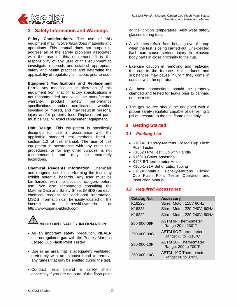
2 Safety Information and Warnings ........................................................................... 2 3 Getting Started ......................................................................................................... 2
3.1 Packing List ...................................................................................................................................... 2 3.2 Required Accessories ...................................................................................................................... 2 3.3 Unpacking ........................................................................................................................................ 3 3.4 Setup ................................................................................................................................................ 3 3.5 Re-assembly .................................................................................................................................... 3
4 Descriptions ............................................................................................................. 4 4.1 Instrument Description ..................................................................................................................... 4
5 Operation .................................................................................................................. 5
6 Troubleshooting ...................................................................................................... 6 6.1 Test Cover (Shutter) Jams ............................................................................................................... 6 6.2 Gas Lines on Test Cover Break ....................................................................................................... 6 6.3 Stirrer Shaft in the Cover Assembly Does Not Rotate ..................................................................... 6 6.4 Gas Leaks and Shooting Flames ..................................................................................................... 7 6.5 Heater Does Not Operate ................................................................................................................ 7 6.6 Stirrer Motor Does Not Operate ....................................................................................................... 7 6.7 Stirrer Motor Runs Hot ..................................................................................................................... 7 6.8 Flexible Motor Coupling Breaks ....................................................................................................... 7
7 Replacement Parts................................................................................................... 8 8 Assembly Diagrams................................................................................................. 9
8.1 K16010 Cover Assembly.................................................................................................................. 9 9 Service .................................................................................................................... 11 10 Storage ................................................................................................................... 11
11 Warranty ................................................................................................................. 11
12 Returned Goods Policy ......................................................................................... 11 Notes ............................................................................................................................ 12

K162X3 Pensky-Martens Closed Cup Flash Point Tester Operation and Instruction Manual
K162X3-Manual -1-
1 Introduction
Koehler Model K16273 Pensky-Martens Closed Cup Flash Point Tester determines the flash points of fuels, lubricating oils, liquid containing suspended solids and liquids that tend to form a surface film during testing. It determines the flash points of a wide range of products by a closed cup method with a flow speed stirring of the sample.
This manual provides operating instructions for the K16273 Pensky-Martens Closed Cup Flash Point Testers, and should be used in conjunction with applicable standard test methods. The following sources are recommended:
1.1 Koehler’s Commitment to Our Customers
Providing quality testing instrumentation and technical support services for research and testing laboratories has been our specialty for more than 50 years. At Koehler, the primary focus of our business is providing you with the full support of your laboratory testing needs. Our products are backed by our staff of technically knowledgeable, trained specialists who are experienced in both petroleum products testing and instrument service to better understand your requirements and provide you with the best solutions. You can depend on Koehler for a full range of accurate and reliable instrumentation as well as support for your laboratory testing programs. Please do not hesitate to contact us at any time with your inquiries about equipment, tests, or technical support.
Toll Free: 1-800-878-9070 (US only) Tel: +1 631 589 3800 Fax: +1 631 589 3815 Email: [email protected] http://www.koehlerinstrument.com
1.2 Recommended Publications
1. American Society for Testing and Materials (ASTM) 100 Barr Harbor Drive West Conshohocken, Pennsylvania 19428-2959, USA Tel: +1 610 832 9500 Fax: +1 610 832 9555 http://www.astm.org email: [email protected]
ASTM Publication:
ASTM D93: Flash Point by Pensky-Martens Closed-Cup Tester
2. International Organization for
Standardization (ISO) 1, rue de Varembé Case postale 56 CH-1211 Geneva 20, Switzerland Tel: 41 22 749 01 11 Fax: 41 22 733 34 30 http://www.iso.org
ISO Publication:
ISO 2719 3. Energy Institute (IP)
61 New Cavendish Street London, WIM 8AR, United Kingdom Tel: 44 (0)20 7467 7100 Fax: 44 (0)20 7255 1472 http://www.energyinstpubs.org.uk/
IP Publication:
IP 34: Closed Flash Point: Pensky-Martens Method
4. Deutsche International Norm (DIN)
http://www.din.de
DIN Publication:
DIN 51758:
5. Federal Test Method (FTM) FTM Publication:
FTM 791-1102 6. American Association of State Highway and
Transportation Officials (AASHTO) AASHTO Publication:
AASHTO T73-811
1.3 Electrical Requirements
Model No Voltage Frequency Amps
K16203 115V 60Hz 6.5A K16273 220-240V 50/60 HZ 3.4 A
K162X3 Pensky-Martens Closed Cup Flash Point Tester Operation and Instruction Manual
K162X3-Manual -2-
2 Safety Information and Warnings
Safety Considerations. The use of this equipment may involve hazardous materials and operations. This manual does not purport to address all of the safety problems associated with the use of this equipment. It is the responsibility of any user of this equipment to investigate, research, and establish appropriate safety and health practices and determine the applicability of regulatory limitations prior to use. Equipment Modifications and Replacement Parts. Any modification or alteration of this equipment from that of factory specifications is not recommended and voids the manufacturer warranty, product safety, performance specifications, and/or certifications whether specified or implied, and may result in personal injury and/or property loss. Replacement parts must be O.E.M. exact replacement equipment. Unit Design. This equipment is specifically designed for use in accordance with the applicable standard test methods listed in section 1.2 of this manual. The use of this equipment in accordance with any other test procedures, or for any other purpose, is not recommended and may be extremely hazardous. Chemical Reagents Information. Chemicals and reagents used in performing the test may exhibit potential hazards. Any user must be familiarized with the possible dangers before use. We also recommend consulting the Material Data and Safety Sheet (MSDS) on each chemical reagent for additional information. MSDS information can be easily located on the internet at http://siri.uvm.edu or http://www.sigma-aldrich.com.
IMPORTANT SAFETY INFORMATION:
As an important safety precaution, NEVER use unregulated gas with the Pensky-Martens Closed Cup Flash Point Tester!
Use in an area that is adequately ventilated, preferably with an exhaust hood to remove any fumes that may be emitted during the test.
Conduct tests behind a safety shield especially if you are not sure of the flash point
or the ignition temperature. Also wear safety glasses during tests.
At all times refrain from bending over the cup when the test is being carried out. Unexpected flash can cause serious injury to exposed body parts in close proximity to the cup.
Exercise caution in removing and replacing the cup in the furnace. Hot surfaces and substances may cause injury if they come in contact with the operator.
All hose connections should be properly clamped and tested for leaks prior to carrying out the tests.
The gas source should be equipped with a proper safety regulator capable of delivering 1 psi of pressure to the test flame assembly.
3 Getting Started
3.1 Packing List
K162X3 Pensky-Martens Closed Cup Flash Point Tester
K16020 PM Test Cup with Handle
K16010 Cover Assembly
K145-8 Thermometer Holder
K160-1-21A Set of Latex Tubing
K162X3-Manual Pensky-Martens Closed Cup Flash Point Tester Operation and Instruction Manual
3.2 Required Accessories
Catalog No. Accessory
K16220 Stirrer Motor, 115V 60Hz
K16228 Stirrer Motor, 220-240V, 60Hz
K16229 Stirrer Motor, 220-240V, 50Hz
250-000-09F ASTM 9F Thermometer Range 20 to 230°F
250-000-09C ASTM 9C Thermometer Range: -5 to +110°C
250-000-10F ASTM 10F Thermometer Range: 200 to 700°F
250-000-10C ASTM 10C Thermometer Range: 90 to 370°C

K162X3 Pensky-Martens Closed Cup Flash Point Tester Operation and Instruction Manual
K162X3-Manual -3-
3.3 Unpacking
This unit comes packed partially disassembled to fit into a pre-formed carton for shipping. 1. Remove the partially disassembled unit and
place on a firm, level table in a room free from excessive drafts where there are no corrosive fumes, excessive moisture, high room temperatures or excessive heat.
2. Ensure that all parts listed on the packing list are present. Inspect the unit and all accessories for damage. If any damage is found, keep all packing materials and immediately report the damage to the carrier. We will assist you with your claim, if requested. When submitting a claim for shipping damage, request that the carrier inspect the shipping container and equipment. Do not return goods to Koehler without written authorization.
3.4 Setup
Equipment Placement: Make sure the instrument in placed on a firm, level table in an area with adequate ventilation or in a hood. The unit may be leveled by making minor turning adjustments to the feet located at the base of the unit. Please note that Koehler does not supply a level with this equipment. Environmental Conditions: The instrument environment must comply with the following conditions for proper setup:
No / Low Dust
No direct sunlight
Not near heating or AC ventilation ducts
No Vibrations
Clearance from other instruments
Temperature Range: 5 to 40°C
Elevation to 2000 meters
Relative Humidity: < 80% Ventilation. A fume hood or exhaust system is required when operating the unit. Flammable vapors and/or steam are generated during operation and must not be permitted to accumulate. A canopy-style hood may be used if the height from the top of the unit to the canopy
is 5 feet or less. The exhaust blower should have a rating of 1000 C.F.M. or greater. Gas Supply. Connect the gas inlet to a regulated low pressure gas supply (0.5 to 1.0 psi). Use only propane, LPG, or natural gas. Do not use direct unregulated pressure from an LPG tank.
NOTE: Be sure Flame Control Switch (Figure 1, Item 3) is in the OFF position when Test Flame Applicator is not in use. Power: Connect the line cords to properly fused and grounded receptacles with the correct voltage as indicated in section 1.3 or on the back of the unit.
WARNING: For safety, disconnect the power when performing any maintenance and/or cleaning. Do NOT turn the power on unless the bath is filled with the proper medium; otherwise, damage may occur to the unit and the warranty will be void.
3.5 Re-assembly
The following components have been disassembled for shipping:
K16010 Cover Assembly
K16020 Cup
K160-3-11 Cup Holder
K160-1-21A
Latex Tubing
1. Place the Cover Assembly into the Cup and
place inside the air bath. Align the cup into the screw holes on top of the brass bell.
2. Place the Cup Holder on the motor mounting
rod at a convenient height and tighten the thumb screw.
3. Install the stirrer motor on the support rod.
Only position the stirrer motor as shown:

K162X3 Pensky-Martens Closed Cup Flash Point Tester Operation and Instruction Manual
K162X3-Manual -4-
After approximately 100 hours of use, remove the motor cover and locate the two drive shafts. Place a few drops of light lubricating oil such as 3 in 1 into the bottom of each shaft and re-install the motor cover.
4. Connect the gas inlet to a regulated low
pressure gas supply (0.5 to 1.0 psi). Use only propane, LPG, or natural gas. Do not use direct unregulated pressure from an LPG tank. Connect two rubber hoses from the cover assembly to main gas pipe outlets.
5. With the unit on a firm, level table, connect
the line cord to a properly fused and grounded receptacle of the correct voltage as indicated in Section 1.3. Be sure the Power switch is off before connecting the line cord. To double check the electrical requirements, refer to the information plate on the side of the instrument. The unit is now ready for operation. Proceed to Operating Instruction.
4 Descriptions
4.1 Instrument Description
1. Main Power Switch. Controls power to the
entire unit. Pressing the switch to the ON position will energize the instrument. Pressing the switch to the OFF position will de-energize the instrument. Switch will illuminate when in the ON position
WARNING: Be sure to completely Power Off instrument prior to performing any service of the instrument. This can only be done by switching the Power Switch to the OFF position. Turning the heating control dial to the off position WILL NOT de-energize the instrument. Only clean instrument or perform maintenance when power indicating light is off.
2. Stirrer Motor Switch. Powers on and off
the Stirrer Motor. 3. Heater Control Knob. The analog dial is
used to control the heating rate of the unit during the test procedure. This dial is non-linear, therefore, the numbers indicated on the dial plate DO NOT refer to specific temperatures or heating rates. The control dial can be switched to an OFF position however, please NOTE that this DOES NOT power off the instrument.
K162X3 Pensky-Martens Closed Cup Flash Point Tester Operation and Instruction Manual
K162X3-Manual -5-
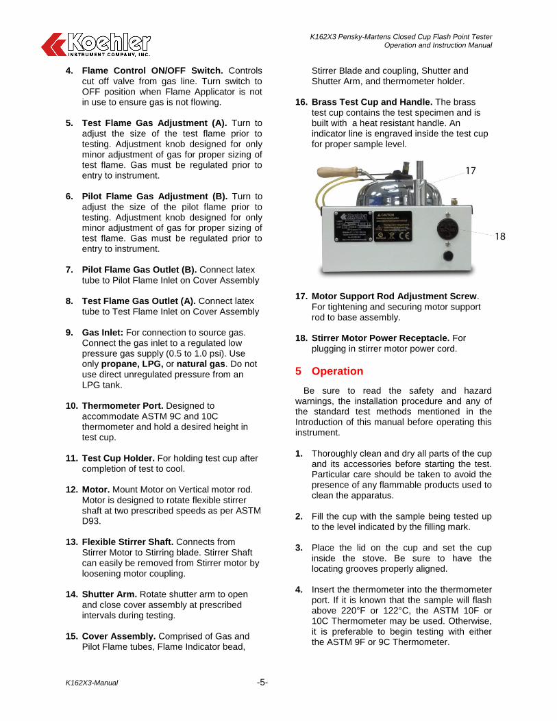
4. Flame Control ON/OFF Switch. Controls cut off valve from gas line. Turn switch to OFF position when Flame Applicator is not in use to ensure gas is not flowing.
5. Test Flame Gas Adjustment (A). Turn to
adjust the size of the test flame prior to testing. Adjustment knob designed for only minor adjustment of gas for proper sizing of test flame. Gas must be regulated prior to entry to instrument.
6. Pilot Flame Gas Adjustment (B). Turn to
adjust the size of the pilot flame prior to testing. Adjustment knob designed for only minor adjustment of gas for proper sizing of test flame. Gas must be regulated prior to entry to instrument.
7. Pilot Flame Gas Outlet (B). Connect latex
tube to Pilot Flame Inlet on Cover Assembly 8. Test Flame Gas Outlet (A). Connect latex
tube to Test Flame Inlet on Cover Assembly 9. Gas Inlet: For connection to source gas.
Connect the gas inlet to a regulated low pressure gas supply (0.5 to 1.0 psi). Use only propane, LPG, or natural gas. Do not use direct unregulated pressure from an LPG tank.
10. Thermometer Port. Designed to accommodate ASTM 9C and 10C thermometer and hold a desired height in test cup.
11. Test Cup Holder. For holding test cup after
completion of test to cool. 12. Motor. Mount Motor on Vertical motor rod.
Motor is designed to rotate flexible stirrer shaft at two prescribed speeds as per ASTM D93.
13. Flexible Stirrer Shaft. Connects from Stirrer Motor to Stirring blade. Stirrer Shaft can easily be removed from Stirrer motor by loosening motor coupling.
14. Shutter Arm. Rotate shutter arm to open and close cover assembly at prescribed intervals during testing.
15. Cover Assembly. Comprised of Gas and Pilot Flame tubes, Flame Indicator bead,
Stirrer Blade and coupling, Shutter and Shutter Arm, and thermometer holder.
16. Brass Test Cup and Handle. The brass test cup contains the test specimen and is built with a heat resistant handle. An indicator line is engraved inside the test cup for proper sample level.
17. Motor Support Rod Adjustment Screw. For tightening and securing motor support rod to base assembly.
18. Stirrer Motor Power Receptacle. For plugging in stirrer motor power cord.
5 Operation
Be sure to read the safety and hazard warnings, the installation procedure and any of the standard test methods mentioned in the Introduction of this manual before operating this instrument. 1. Thoroughly clean and dry all parts of the cup
and its accessories before starting the test. Particular care should be taken to avoid the presence of any flammable products used to clean the apparatus.
2. Fill the cup with the sample being tested up
to the level indicated by the filling mark. 3. Place the lid on the cup and set the cup
inside the stove. Be sure to have the locating grooves properly aligned.
4. Insert the thermometer into the thermometer
port. If it is known that the sample will flash above 220°F or 122°C, the ASTM 10F or 10C Thermometer may be used. Otherwise, it is preferable to begin testing with either the ASTM 9F or 9C Thermometer.

K162X3 Pensky-Martens Closed Cup Flash Point Tester Operation and Instruction Manual
K162X3-Manual -6-
5. Light the test flame with an external ignition source. Adjust the flame using the coarse adjustment screw. Use the valve screw (shown in the picture, top right) to adjust the flame so that it is 5/32” diameter, the same size as the bead provided for comparison (indicated by white arrow). The pilot flame (indicated by black arrow) is provided in case the test flame extinguishes upon dipping.
6. Adjust the dial on the variable heat control
until the temperature reading on the thermometer increases to no less than 9°F, or more than 11°F per minute. Turn the dial fully clockwise and back counterclockwise to set the temperature. The dial is non-linear.
7. Connect the stirrer to the stirrer motor by
turning the placement screw (shown below) counterclockwise and inserting the flexible stirrer. Turn the placement screw clockwise to tighten. Make sure the flexible stirrer has a smooth curve when inserting into the motor. If it is too tight or too loose, the shear stress will break it.
NOTE: The motor coupling on the right side of the motor (closest to the mounting rod) rotates at a higher RPM in accordance to ASTM D93 Procedure B. The motor coupling on the opposite side rotates at a lower RPM in accordance to ASTM D93 Procedure A.
8. Shut off the stirrer motor during the application of the test flame. Apply the test flame at each temperature reading by turning the fiber knob clockwise. The cover assembly will open and the test flame will dip into the sample cup. Apply the test flame burner so that the test flame is lowered in one-half second, left in its lowered position for one second, and quickly raised to it’s high position. Dip the test flame every 2°F, up to 220°F. For temperature ranges above 220°F, apply the test flame at each temperature reading of 5°F.
9. Record the temperature when the flash point
occurs. 10. For full details on the testing procedure,
refer to standard test methods listed in section 1.2.
6 Troubleshooting
6.1 Test Cover (Shutter) Jams
Solution:
Disassemble cover assembly and clean parts with appropriate solvent.
Check for smooth operation
6.2 Gas Lines on Test Cover Break
Solution:
Pilot flame gas line: Replace by loosening the set screw and inserting a new ignitor tube and nozzle assembly.
Test flame gas line: Replace the entire pivot block and jet tube assembly (K160-1-8A) which is held in place by two screws.
6.3 Stirrer Shaft in the Cover Assembly Does Not Rotate
Solution:
Remove the propellers from shaft (screws)
Remove shaft from cover assembly and clean. Replace if needed.
Return shaft to the cover assembly and check for smooth operation.
Replace propellers in proper order.

K162X3 Pensky-Martens Closed Cup Flash Point Tester Operation and Instruction Manual
K162X3-Manual -7-
6.4 Gas Leaks and Shooting Flames
Solution:
Check for delivery pressure of the supply gas (1 psi max)
Close valve all the way and check for leakage. Replace valve and/or latex tubing if need be.
6.5 Heater Does Not Operate
Solution:
Access heater by loosening the screws in the back support and swing bell assembly out of the way.
Check heater for continuity. If open, replace heater.
Replace variable control. Access via bottom of heater unit housing.
6.6 Stirrer Motor Does Not Operate
Solution:
Ensure the power cord is plugged into the receptacle.
While unplugged, remove cover from motor housing and check drive belt. Replace if needed.
Remove back cover of housing and check for clearance between the cover and the fan.
6.7 Stirrer Motor Runs Hot
Solution:
Check electrical service for compatibility.
It is normal for the stirrer housing to be warm.
6.8 Flexible Motor Coupling Breaks
Solution
Replace the flexible stirrer coupling assembly (K160-9) by inserting the end receptacle into the drive motor and cover assembly.
To prevent premature breakage of the motor spring:
- Check the stirrer shaft in cover assembly for unrestricted motion.
- Position the drive motor as high as possible on the support rod and ensure that the coupling is a gentle arc between the drive motor and cover assembly.

K162X3 Pensky-Martens Closed Cup Flash Point Tester Operation and Instruction Manual
K162X3-Manual -8-
7 Replacement Parts
Part Number Replacement Part K16010
Cover Assembly
K16020 Pensky-Martens Test Cup
K160-3-3 Brass Bell
K160-3-2 Cast Iron Bell
K160-1-14 Thermometer Ferrule Adapter
K145-8 Thermometer Ferrule
K160-9 Flexible Shaft and Coupling
K16220 Stirrer Motor, 115V, 60 Hz
225-115-002 Brick Heater, 115V, 1000W †
K16228 Stirrer Motor, 220-240V 60 Hz
K16229 Stirrer Motor, 220-240V, 50 Hz
225-230-002 Brick Heater, 220-240V, 1000W ‡
K160-1-8A Pivot, Block and Jet Tube Assembly
K160-3-12 Main Gas Pipe Assembly
Note: † For 115V Unit (K16203) ONLY ‡ For 220-240V Unit (K16273) ONLY
K162X3 Pensky-Martens Closed Cup Flash Point Tester Operation and Instruction Manual
K162X3-Manual -9-
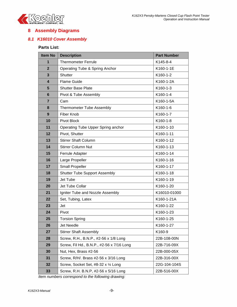
8 Assembly Diagrams
8.1 K16010 Cover Assembly
Parts List:
Item No Description Part Number
1 Thermometer Ferrule K145-8-4
2 Operating Tube & Spring Anchor K160-1-1E
3 Shutter K160-1-2
4 Flame Guide K160-1-2A
5 Shutter Base Plate K160-1-3
6 Pivot & Tube Assembly K160-1-4
7 Cam K160-1-5A
8 Thermometer Tube Assembly K160-1-6
9 Fiber Knob K160-1-7
10 Pivot Block K160-1-8
11 Operating Tube Upper Spring anchor K160-1-10
12 Pivot, Shutter K160-1-11
13 Stirrer Shaft Column K160-1-12
14 Stirrer Column Nut K160-1-13
15 Ferrule Adapter K160-1-14
16 Large Propeller K160-1-16
17 Small Propeller K160-1-17
18 Shutter Tube Support Assembly K160-1-18
19 Jet Tube K160-1-19
20 Jet Tube Collar K160-1-20
21 Igniter Tube and Nozzle Assembly K16010-01000
22 Set, Tubing, Latex K160-1-21A
23 Jet K160-1-22
24 Pivot K160-1-23
25 Torsion Spring K160-1-25
26 Jet Needle K160-1-27
27 Stirrer Shaft Assembly K160-9
28 Screw, R.H., B.N.P., #2-56 x 1/8 Long 22B-108-00N
29 Screw, Fil Hd., B.N.P., #2-56 x 7/16 Long 22B-716-09X
30 Nut, Hex, Brass #2-56 22B-000-05X
31 Screw, R/H/. Brass #2-56 x 3/16 Long 22B-316-00X
32 Screw, Socket Set, #8-32 x ¼ Long 22G-104-104S
33 Screw, R.H. B.N.P, #2-56 x 5/16 Long 22B-516-00X
Item numbers correspond to the following drawing:

K162X3 Pensky-Martens Closed Cup Flash Point Tester Operation and Instruction Manual
K162X3-Manual -10-
Cover Assembly Diagram:

K162X3 Pensky-Martens Closed Cup Flash Point Tester Operation and Instruction Manual
K162X3-Manual -11-
9 Service
Under normal operating conditions and with routine maintenance, the K162X3 Manual Pensky-Martens Flash Point Tester should not require service. Any service problem can be quickly resolved by contacting Koehler’s technical service department either by letter, phone, fax, or email. In order to assure the fastest possible service, please provide us with the following information.
Model Number:
Serial Number:
Date of Shipment:
10 Storage
This laboratory test instrument is equipped with electrical components. Storage facilities should be consistent with an indoor laboratory environment. This testing equipment should not be subjected to extremes of temperature and/or moisture.
This equipment was shipped from the factory in a corrugated cardboard container. If long term storage is anticipated, re-packing the instrument in a water-resistant container is recommended to ensure equipment safety and longevity.
11 Warranty
We, at Koehler, would like to thank you for your equipment purchase, which is protected by the following warranty. If within one (1) year from the date of receipt, but no longer than fifteen (15) months from the date of shipment, Koehler equipment fails to perform properly because of defects in materials or workmanship, Koehler Instrument Company, Inc. will repair or, at its sole discretion, replace the equipment without charge F.O.B. its plant, provided the equipment has been properly installed, operated, and maintained. Koehler Instrument Company must be advised in writing of the malfunction and authorize the return of the product to the factory. The sole responsibility of Koehler Instrument Company and the purchaser’s exclusive remedy for any claim arising out of the purchase of any product is the repair or replacement of the product. In no event shall the cost of the purchaser’s remedy exceed the purchase price, nor shall Koehler Instrument Company be liable for any special, indirect, incidental, consequential, or exemplary damages. KOEHLER INSTRUMENT COMPANY, INC. DISCLAIMS ALL OTHER WARRANTIES, EXPRESSED OR IMPLIED, INCLUDING ANY
IMPLIED WARRANTIES OF FITNESS FOR A PARTICULAR PURPOSE. Please save the shipping carton in the event the equipment needs to be returned to the factory for warranty repair. If the carton is discarded, it will be the purchaser’s responsibility to provide an appropriate shipping carton.
12 Returned Goods Policy
To return products for credit or replacement, please contact Koehler Customer Service with your purchase order number, our packing list/invoice number, the item(s) to be returned and the reason for the return. You will be issued a Returned Authorization (RA) number, which must be prominently displayed on the shipping container when you return the material to our plant. Shipping containers without an RA number prominently displayed with will be returned to the sender. Goods must be returned freight prepaid. Returns will be subject to a restocking charge, the application of which will depend upon the circumstances necessitating the return. Some returns cannot be authorized, including certain products purchased from outside vendors for the convenience of the customer, products manufactured on special order, products shipped from the factory past ninety (90) days, and products which have been used or modified in such a way that they cannot be returned to stock for future sale.

K162X3 Pensky-Martens Closed Cup Flash Point Tester Operation and Instruction Manual
K162X3-Manual -12-
Notes

K162X3 Pensky-Martens Closed Cup Flash Point Tester Operation and Instruction Manual
K162X3-Manual -13-
Notes

K162X3 Pensky-Martens Closed Cup Flash Point Tester Operation and Instruction Manual
K162X3-Manual -14-
Notes