Embed Size (px)
Citation preview
OPERATING MANUAL PSP 601A-6
SECTION 1
AIRCRAFT - GENERAL
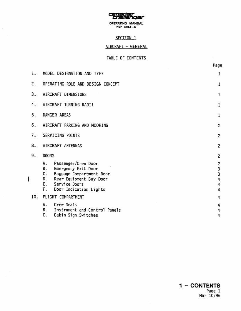
TABLE OF CONTENTS
MODEL DESIGNATION AND TYPE
OPERATING ROLE AND DESIGN CONCEPT
AIRCRAFT DIMENSIONS
AIRCRAFT TURNING RADII
DANGER AREAS
AIRCRAFT PARKING AND MOORING
SERVICING POINTS
AIRCRAFT ANTENNAS
DOORS
A. Passenger/Crew Door B. Emergency Exit Door C. Baggage Compartment Door D. Rear Equipment Bay Door E. Service Doors F. Door Indication Lights
FLIGHT COMPARTMENT
A. Crew Seats B. Instrument and Control Panels C. Cabin Sign Switches
Page
1
1
1
1
1
2
2
2
2
2 3 3 4 4 4
4
4 4 4
1 - CONTENTS Page 1
Mar 10/95
OPERATING MANUAL PSP 601A-6
LIST OF ILLUSTRATIONS
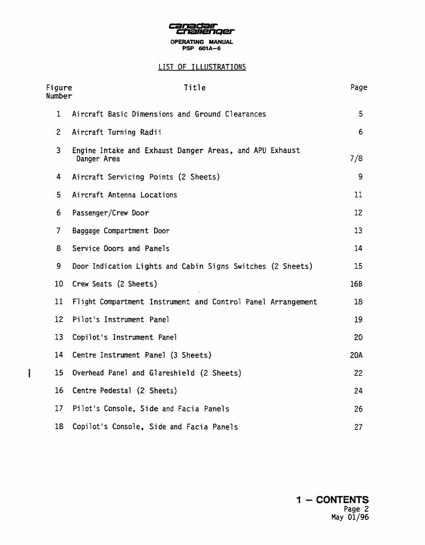
Figure T i t l e Page Number
1 Aircraft Basic Dimensions and Ground Clearances 5
2 Aircraft Turning Radii 6
3 Engine Intake and Exhaust Danger Areas, and APU Exhaust
4
5
6
7
8
9
10
11
12
13
14
15
16
17
18
Danger Area
Aircraft Servicing Points (2 Sheets)
Aircraft Antenna Locations
Passenger/Crew Door
Baggage Compartment Door
Service Doors and Panels
Door Indication Lights and Cabin Signs Switches (2 Sheets)
Crew Seats (2 Sheets)
Flight Compartment Instrument and Control Panel Arrangement
Pi lot 's Instrument Panel
Copilot's Instrument Panel
Centre Instrument Panel (3 Sheets)
Overhead Panel and Glareshield (2 Sheets)
Centre Pedestal (2 Sheets)
Pi lot 's Console, Side and Facia Panels
Copilot's Console, Side and Facia Panels
7/8
9
11
12
13
14
15
16B
18
19
20
20A
22
24
26
27
1 - CONTENTS Page 2
May 01/96
OPERATING MANUAL PSP 601A-6
SECTION 1
AIRCRAFT - GENERAL
1. MODEL DESIGNATION AND TYPE
The aircraft, named Challenger, is manufactured by Canadair Limited. The Challenger model covered by this manual is the CL-601, Model 2B16, Variant 601-3A, {Variant 601-3R for airplanes 5135 and subsequent), powered by two General Electric CF34 turbofan engines.
2. OPERATING ROLE AND DESIGN CONCEPT
Primarily, the Challenger is a long-range (transcontinental) business aircraft operated by a crew of two. The aircraft is designed to carry up to 19 passengers in spacious comfort over long distances. The combination of a technologically advanced supercritical wing, quiet and efficient engines, and a wide body enables the Challenger to achieve a high standard of performance, economy and passenger comfort.
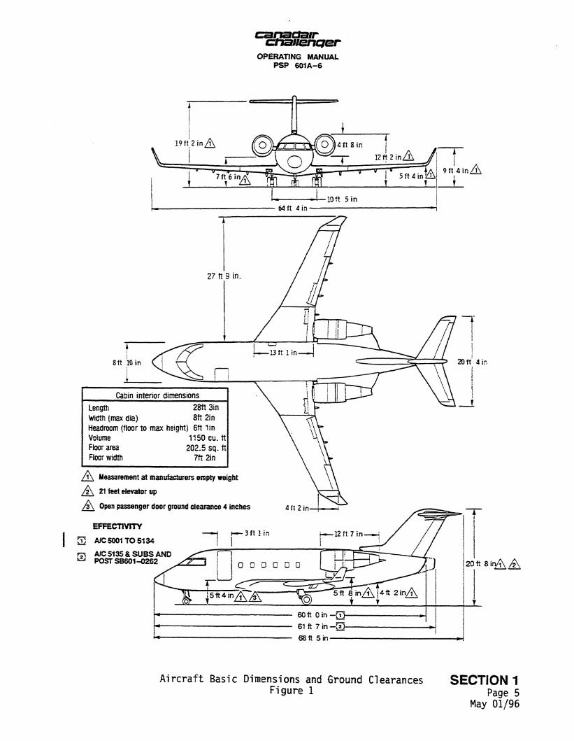
3. AIRCRAFT DIMENSIONS (Figure 1)
All basic dimensions, including ground clearances, are given in Figure 1.
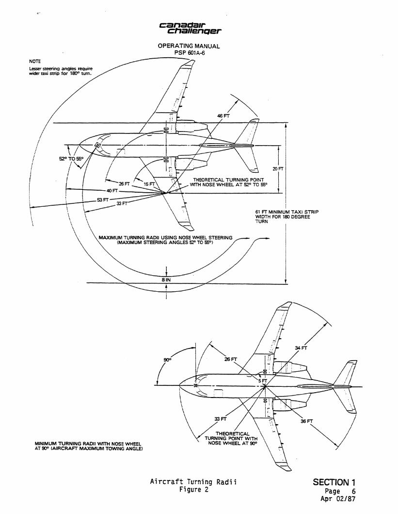
4. AIRCRAFT TURNING RADII (Figure 2)
Using the nose gear steering control wheel, the pilot can turn the aircraft, during taxiing, without differential braking. Figure 2 shows the turning radii applicable to the maximum nose wheel steering angle of 55 degrees, the minimum taxi strip width required for a 180-degree turn at the maximum steering angle, and the turning radii for the maximum towing angle of 90 degrees.
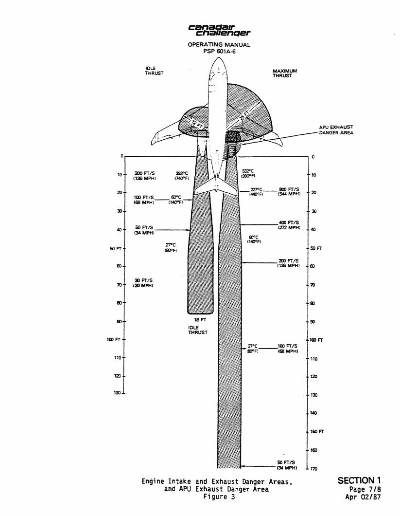
5. DANGER AREAS (Figure 3)
I t is essential that persons involved with engine or APU running are aware of the danger areas in front of and to the rear of the engine(s). Before running an engine or the APU, the information illustrated in figure 3 must be used to consider the safety of persons, equipment and buildings in the vicinity of the aircraft.
SECTION 1 Page 1
Apr 10/95
OPERATING MANUAL PS? 6 0 1 A - 6
AIRCRAFT PARKING AND MOORING
When the aircraft i s stationary on the ground, precautions must be taken to ensure safety of personnel and equipment. The extent of safety measures to be observed depends upon the prevailing or expected weather conditions and the expected length of time the aircraft will be stationary. For complete instruct ions on parking and mooring the a ircraf t , refer to Ground Handling and Servic ing Information, PSP 601-13.
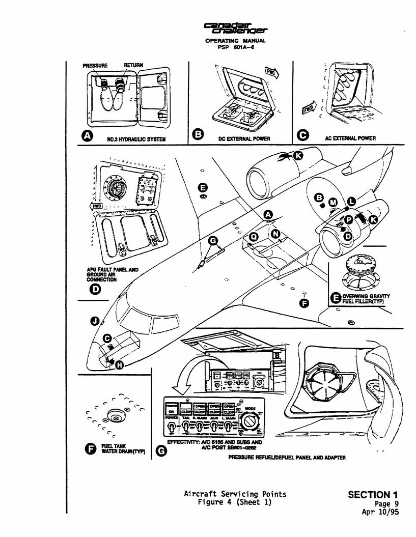
SERVICING POINTS (Figure 4)
Location and details for al l aircraft servicing points are shown in Figure 4 .
AIRCRAFT ANTENNAS (Figure 5)
Location and nomenclature of the aircraft antennas are given in Figure 5.
DOORS
The aircraft is provided with a passenger/crew door, a baggage compartment door, a rear equipment bay door, landing gear doors and various small doors which provide access to servicing points. An overwing emergency exit door is provided on the right side of the passenger compartment.
The baggage compartment and emergency exit doors are of the plug type which open inward; all other doors open outward. All doors are flush with the aircraft outer skin when closed*
A. Passenger/Crew Door (Figure 6)
The entrance door is electrically or manually operated and downward opening, with the stairs forming an integral part of the door structure. I t s movement i s controlled .by a counterbalance system of gas springs.
An electrical power assist system provides an optional means of closing the door from inside the aircraft. A control switch, labelled CABIN DOOR, i s located just forward of the entrance door. Holding the switch to the RAISE position activates the system which raises the door from any open position up to the closed position. Once the switch i s released, the door can s t i l l be operated manually. A pull-in handle on the rear handrail can be used to reduce the force required to close the door manually from the inside of the aircraft.
The latching mechanism is operated by an internal single-lever handle, located on the forward side of the steps, a T-handle which i s recessed in a r i s er of a step and an external handle with a keylock.
SECTION 1 Page 2
Apr 02/87
canadair chaliBnqer OPERATING MANUAL
PSP 601A-6
On aircraft 5041 and 5146, a vent flap linked with the external handle locking mechanism is located just above the external handle recess, to ensure that the cabin cannot be fully pressurized unless the door is correctly locked. The vent opens whenever the external handle is moved from the stowed position. A viewing window adjacent to the T-handle displays the legends LOCKED and UNLOCKED to indicate the position of the external handle.
Once closed, the door is latched from the inside by pushing the internal handle downward. The T-handle is then pulled out of its recess to stow the external handle, which clicks audibly when stowed. Verification that the external handle is stowed can be made by ensuring that the internal handle cannot be pulled up. After this check, the T-handle must be stowed in the riser of the step.
From outside the airplane, the door is latched by rotating the external handle fully clockwise to engage the door latches and stow the pull-out handle. Pushing the external handle then places it in the stowed position.
The door is unlocked from the inside when the internal handle is pulled upward, ejecting the external handle from its pocket. The door is then unlatched by continuing to pull the internal handle upward. As the door opens, the handrails unfold upward.
The door unlocks from the outside by the operation of a PUSH trigger in the external handle, which is ejected from its pocket. To unlatch the door, the external handle is then turned 45 degrees counterclockwise. Pull-out and pull-in handles are also provided to assist the operator in opening or closing the door from the outside or inside, respectively. When the door is fully open, a door support leg extends to the ground.
B. Emergency Exit Door
For details of the emergency exit door, refer to Section 8.
C. Baggage Compartment Door (Figure 7)
The baggage compartment door is located on the left side of the aircraft immediately aft of the passenger compartment. The door opens inwards and upwards, and is assisted during opening by balance springs. The door is held closed by two plungers which are operated by an external and an internal handle.
Two proximity switches are installed to provide an indication in the flight compartment when the door is not safely closed.
The external handle stows flush into a pocket in the door outer skin and, in this position, acts as a lock for the latching mechanism. The handle has a keylock which unlocks or locks a PUSH trigger. The PUSH trigger, when pressed, ejects the handle which can then be turned to release the locking plungers and to open the door.
SECTION 1 Page 3
Aug 14/02
canadair chaJienper OPERATING MANUAL
PSP 601A-6
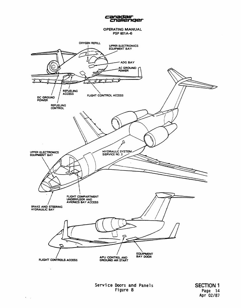
D. Rear Equipment Bay Door (Figure 8)
The rear equipment bay door, located at the bottom of the rear fuselage, provides access to the APU, engine oil replenishment system, air conditioning units, replenishment points for No. 1 and No. 2 hydraulic systems, and the aircraft battery. The door opens downward, has two integral steps, and is secured at the forward edge by two hinges which are equipped with quick-release pins to facilitate easy door removal.
The rear equipment bay door is held closed by two plungers at the rear edge, and is opened and closed by a handle. Handle operation is the same as for the baggage compartment door, with the exception that the rear equipment bay door must be supported during opening because of opening direction.
E. Service Doors (Figure 8)
Quick-release service door sand panels are provided for easy access to the servicing points throughout the aircraft. Location and nomenclature of these doors and panels are given in Figure 8.
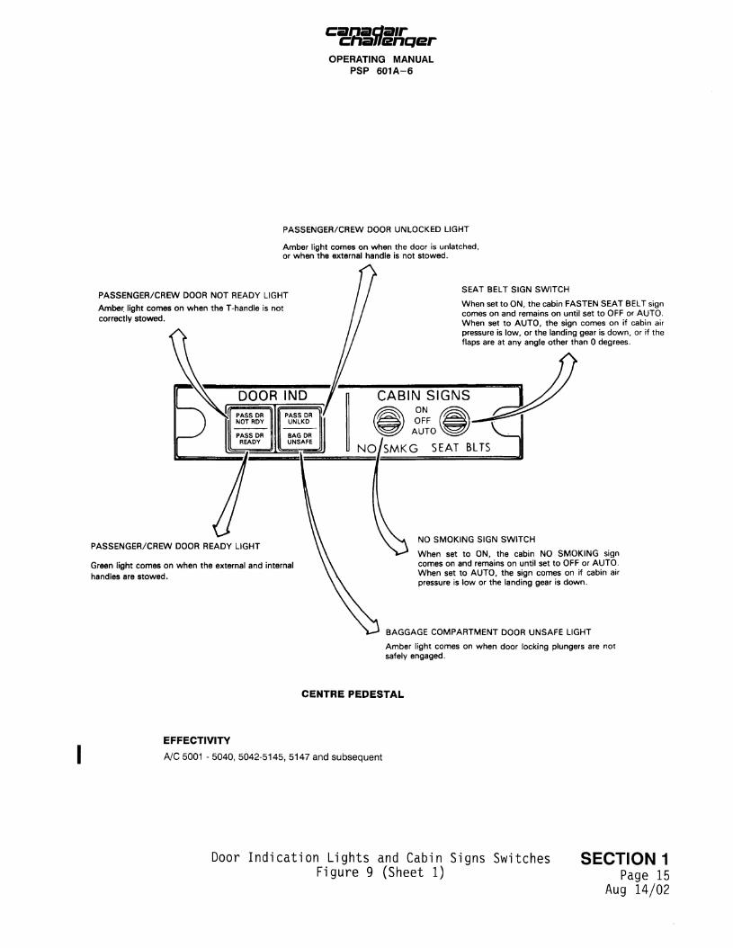
F. Door Indication Lights (Figure 9)
For operation of the DOOR INDICATION lights, refer to Figure 9.
FLIGHT COMPARTMENT
Miscellaneous items in the flight compartment include a portable fire extinguisher, located behind the copilot's seat on the bulkhead that separates the flight and passenger compartments, two oxygen masks, two cup holders, and storage boxes and pouches for checklists, etc.
The windshield centre post incorporates a pilot's eye locator to enable seat adjustments for optimum field of vision.
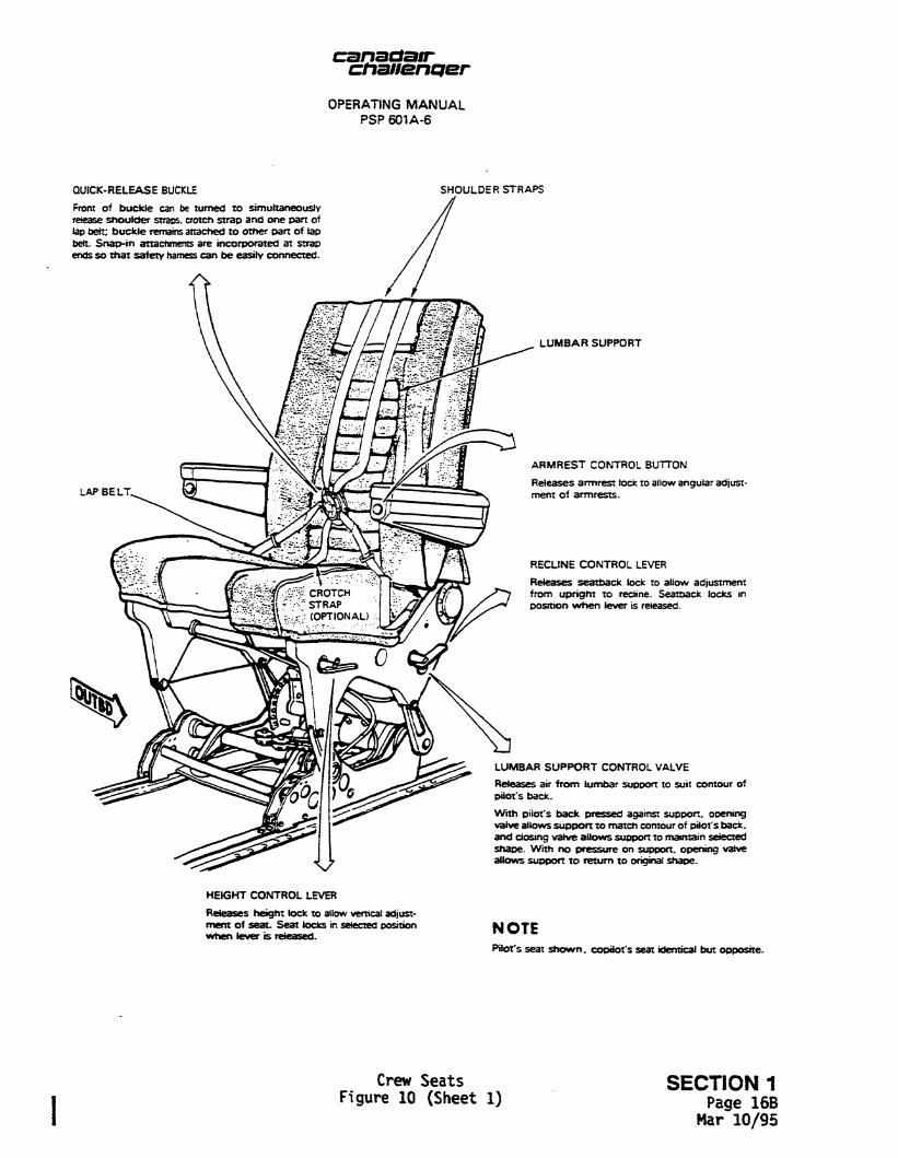
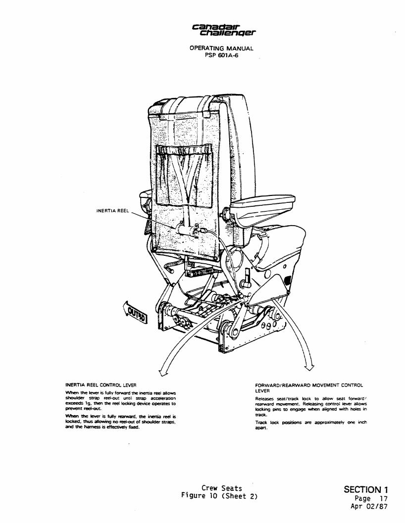
A. Crew Seats (Figure 10)
The pilot's and copilot's seats are identical except that certain controls are installed on opposite sides. On both seats, inertia reel and forward/rearward controls are located inboard, and lumbar support, height and reclining controls are located outboard.
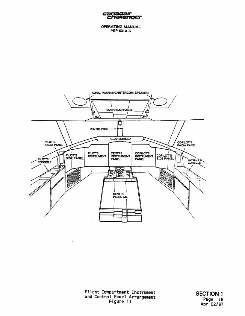
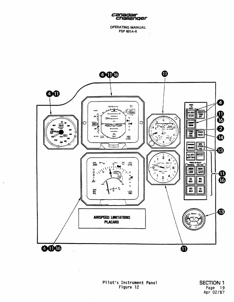
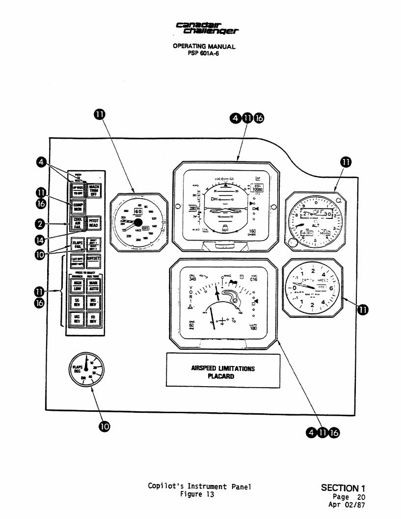
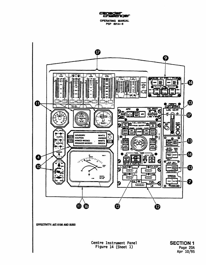
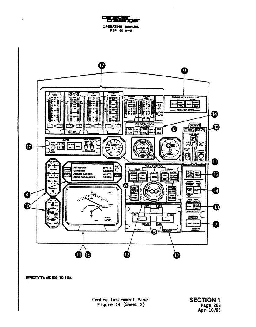
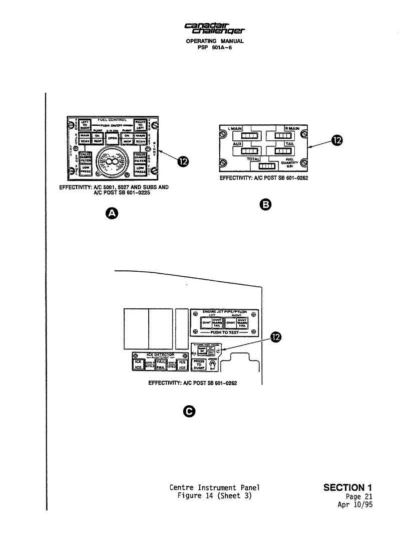
B. Instrument and Controls panels (Figure 11)
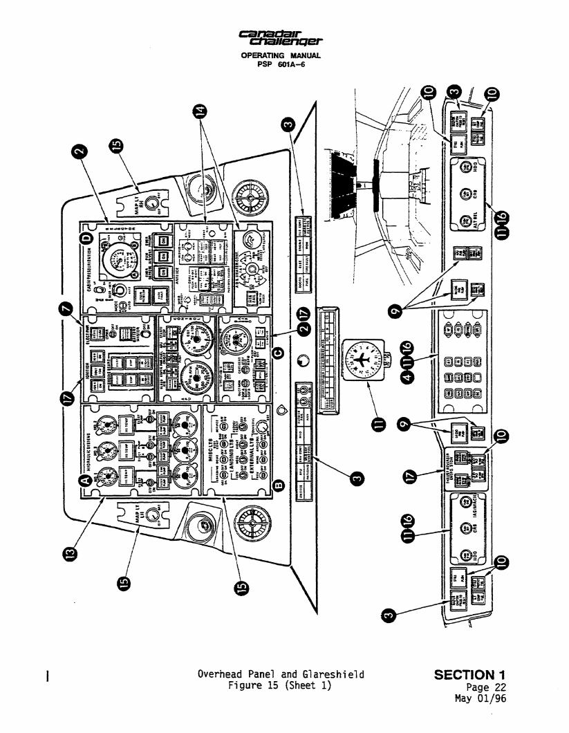
The instrument and control panels are arranged as shown in Figure 11, and are presented in Figures 12 to 18.
Circled numbers on the instrument and control panels refer to sections of this manual where information on the item can be found.
c. Cabin 5ign Switches (Figure 9)
For operation of the NO SMOKING and FASTEN SEAT BELT signs in the passenger cabin, refer to Figure 9.
SECTION 1 Page 4
Mar 10/95
OPERATING MANUAL PSP 601A-6
t i
8 ft 10 in
] _ Cabin interior dimensions |
[ Length Width {max dia)
28ft 3in I 8ft 2in
Headroom (floor to max height) 6ft 1 in | Volume Floor area Floor width
1150 cu. ft 202.5 sq. ft
7ft 2in
/ \ Measurement at manufacturers empty weight
y£ \ 21 feet elevator up
/ s \ Open passenger door ground clearance 4 inches
EFFECTIYITY
J Ji] A/C5001TO5134
r^ A/C 5135 & SUBS AND ^ POSTSB601-O262 20 ft 8 i r j ^ ^
Aircraft Basic Dimensions and Ground Clearances SECTION 1 Figure 1 p a g e 5
May 01/96
canactatr ctiauencjer
OPERATING MANUAL PSP 601A-6
, MAXIMUM TURNING RADII USING NOSE WHEEL STEERING {MAXIMUM STEERING ANGLES I
61 FT MINIMUM TAXI STRIP WIDTH FOR 180 DEGREE TURN
MINIMUM TURNING RADII WITH NOSE WHEEL AT 90° (AIRCRAFT MAXIMUM TOWING ANGLE)
Aircraft Turning Radii SECTION 1 Figure 2 pa g e 6
Apr 02/87
ctiauenQer OPERATING MANUAL
PSP 601A-6
IDLE THRUST MAXIMUM
THRUST
50FT +
100FT +
110 +
120 +
1301
4 SOFT
APU EXHAUST DANGER AREA
+100 FT
+ 150 FT
4-160
J-170
Engine Intake and Exhaust Danger Areas, and APU Exhaust Danger Area
Figure 3
SECTION 1 Page 7/8
Apr 02/87

OPERATING MANUAL PSP 601A-6
N0.3HYDRAUUC SYSTEM DC EXTERNAL POWER AC EXTERNAL POWER
PRESSURE REFUEUDEFUEL PANEL AND ADAPTER
Aircraft Servicing Points Figure 4 {Sheet 1)
SECTION 1 Page 9
Apr 10/95
OPERATING MANUAL PSP 601A-6
© BRAKE ACCUMULATOR CHARGING POINTS AND INTERPHONE © OXYGEN SYSTEM CHARGING
VALVE AND GAUGE
ACCUMULATOR PRESSURE GAUGE
^ ^ k * RESERVOIR FILL
N0.1 HYDRAULIC SYSTEM AND REAR INTERPHONE
OIL LEVEL CONTROL PANEL
NO.3 HYDRAULIC SYSTBt RESBWOff) FILLS CONNECTION -
© Aircraft Servicing Points
Figure 4 (Sheet 2)
MO J HYDRAULIC SYSTEM ACCUMULATOR CHARGING POtflTAND PRESSURE GAUGE
SECTION 1 Page 10
Apr 10/95
chauenper OPERATING MANUAL
PSP 601A-6
Aircraft Antenna Locations Figure 5
SECTION 1 Page 11
Mar 10/95
canadair challenQsr
OPERATING MANUAL PSP 601A-6
EFFECTIVITY
Q] A/C 5041 and 5146 CABIN DOOR SWITCH
o C3 3 O D
EXTERNAL HANDLE
Passenger/Crew Door SECTION 1 Figure 6 Page 12
Aug 14/02
OPERATING MANUAL PSP 601A-6
BALANCE SPRING BOXES
PLUNGER
GUIDE TRACKS
HANDLE
HANDLE KEY LOCK
HANDLE HANDLE UNSTOW BUTTON
Baggage Compartment Door Figure 7 SECTION 1
Page 13 Apr 02/87
OXYGEN REFILL
OPERATING MANUAL PSP 601A-6
UPPER ELECTRONICS EQUIPMENT BAY
DC GROUND POWER
FLIGHT CONTROL ACCESS
REFUELING CONTROL
7 UPPER ELECTRONICS EQUIPMENT BAY
K
HYORAUUC SYSTEM* SERVICE NO. 3
FLIGHT COMPARTMENT UNDERFLOOR ANO AVIONICS BAY ACCESS
BRAKE AND STEERING HYDRAULIC BAY
\r<8F FUGHT CONTROLS ACCESS
APU CONTROL AND GROUND AIR START
EQUIPMENT BAY DOOR
Service Doors and Panels SECTION 1 Figure 8 Page 14
Apr 02/87
chaJlenQer OPERATING MANUAL
PSP 601A-6
PASSENGER/CREW DOOR UNLOCKED LIGHT
Amber light comes on when the door is unlatched, or when the external handle is not stowed.
PASSENGER/CREW DOOR NOT READY LIGHT Amber light comes on when the T-handle is not correctly stowed.
SEAT BELT SIGN SWITCH
When set to ON, the cabin FASTEN SEAT BELT sign comes on and remains on until set to OFF or AUTO. When set to AUTO, the sign comes on if cabin air pressure is low, or the landing gear is down, or if the flaps are at any angle other than 0 degrees.
CABIN SIGNS
^ \ 0 N ff*<=^\ 0 F F
AUTO
NO/SMKG SEAT BLTS
PASSENGER/CREW DOOR READY LIGHT
Green light comes on when the external and internal handles are stowed.
NO SMOKING SIGN SWITCH
When set to ON, the cabin NO SMOKING sign comes on and remains on until set to OFF or AUTO. When set to AUTO, the sign comes on if cabin air pressure is low or the landing gear is down.
BAGGAGE COMPARTMENT DOOR UNSAFE LIGHT
Amber light comes on when door locking plungers are not safely engaged.
CENTRE PEDESTAL
EFFECTIVITY
A/C 5001 - 5040, 5042-5145, 5147 and subsequent
Door Indicat ion Lights and Cabin Signs Switches S E C T I O N 1 Figure 9 (Sheet 1) pa g e 15
Aug 14/02
dhsjJenqer OPERATING MANUAL
PSP 6 0 1 A - 6
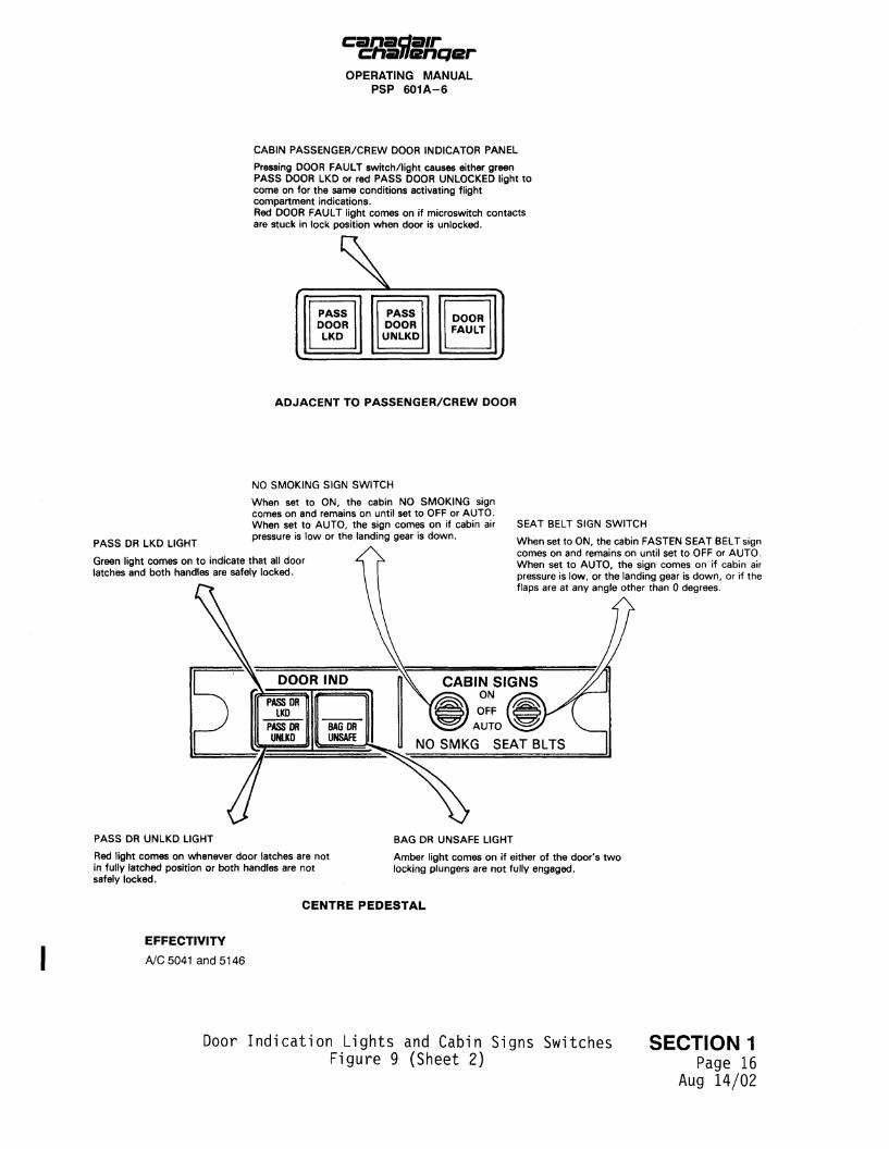
CABIN PASSENGER/CREW DOOR INDICATOR PANEL
Pressing DOOR FAULT switch/light causes either green PASS DOOR LKD or red PASS DOOR UNLOCKED light to come on for the same conditions activating flight compartment indications. Red DOOR FAULT light comes on if microswitch contacts are stuck in lock position when door is unlocked.
PASS DOOR LKD
PASS DOOR UNLKD
DOOR FAULT
ADJACENT TO PASSENGER/CREW DOOR
PASS DR LKD LIGHT
NO SMOKING SIGN SWITCH
When set to ON, the cabin NO SMOKING sign comes on and remains on until set to OFF or AUTO. When set to AUTO, the sign comes on if cabin air pressure is low or the landing gear is down.
Green light comes on to indicate that all door latches and both handles are safely locked.
SEAT BELT SIGN SWITCH
When set to ON, the cabin FASTEN SEAT BELT sign comes on and remains on until set to OFF or AUTO. When set to AUTO, the sign comes on if cabin air pressure is low, or the landing gear is down, or if the flaps are at any angle other than 0 degrees.
CABIN SIGNS ON
OFF
AUTO
NO SMKG SEAT BLTS
PASS DR UNLKD LIGHT
Red light comes on whenever door latches are not in fully latched position or both handles are not safely locked.
BAG DR UNSAFE LIGHT
Amber light comes on if either of the door's two locking plungers are not fully engaged.
C E N T R E P E D E S T A L
EFFECTIV ITY
A/C5041 and 5146
Door Indicat ion Lights and Cabin Signs Switches S E C T I O N 1 Figure 9 (Sheet 2) pa g e 16
Aug 14/02
OPERATING MANUAL PSP 601A-6
THIS PAGE INTENTIONALLY LEFT BLANK
SECTION 1 Page 16A
Mar 10/95
canactatr ctiauencjer
OPERATING MANUAL PSP 601A-6
QUICK-RELEASE BUCKLE
Front of buckle can be turned to simultaneously release shoulder straps, crotch strap and one pan of lap belt; buckle remains attached to other pari of lap belt. Snap-in attachments are incorporated at strap ends so that safety harness can be easily connected.
SHOULDER STRAPS
LAP BELT,
LUMBAR SUPPORT
ARMREST CONTROL BUTTON
Releases armrest lock to allow angular adjustment of armrests.
RECUNE CONTROL LEVER
Releases seatback lock to allow adjustment from upright to recline. Seatback locks m position when lever is released.
LUMBAR SUPPORT CONTROL VALVE
Releases air from lumbar support to suit contour of pilot's back.
With pilot's back pressed against support, opening valve allows support to match contour of pilot's back. and dosing valve allows support to maintain selected shape. With no pressure on support, opening varve allows support to return to original shape.
HEIGHT CONTROL LEVER
Releases height lock to allow vertical adjustment of seat. Seat locks in selected position when lever is released. NOTE
Pilot's seat shown, copilot's seat identical but opposite.
Crew Seats Figure 10 (Sheet 1)
SECTION 1 Page 16B
Mar 10/95
chaueneter OPERATING MANUAL
PSP 601A-6
INERTIA REEL
INERTIA REEL CONTROL LEVER
When the lever is fully forward The inertia reel allows shoulder strap reei-ou: until strap acceleration exceeds Ig. then the reel locking device operates to prevent reel-out.
When the lever is fully rearward, the inertia reel is locked, thus allowing no reel-out of shoulder straps. and the harness is effectivery fixed.
FORWARD/REARWARD MOVEMENT CONTROL LEVER
Releases seat/ track lock to allow sea: forward/
rearward movement. Releasing control lever allows locking pins to engage when aligned with holes in track.
Track lock positions are approximately one inch apart.
Crew Seats Figure 10 (Sheet 2)
SECTION 1 Page 17
Apr 02/87
OPERATING MANUAL PSP 601A-6
AURAL WARNING/JNTERCOM SPEAKBiS
Flight Compartment Instrument and Control Panel Arrangement
Figure 11 SECTION 1
Page 18 Apr 02/87
OPERATING MANUAL PSP 601A-6
Pi lo t ' s Instrument Panel Figure 12
SECTION 1 Page 19
Apr 02/87
OPERATING MANUAL PSP601A-6
Copilot's Instrument Panel Figure 13
SECTION 1 Page 20
Apr 02/87
OPERATING MANUAL PSP 601A-6
EFFECTMTY: A/C 5136 AM) SUBS
Centre Instrument Panel Figure 14 {Sheet 1)
SECTION 1 Page 20A
Apr 10/95
OPERATING MANUAL PSP 6C1A-6
©
E*GJNE JET WE/FYIOK urt
BFFECTMTY: JVC 8001 TO 6134
Centre Instrument Panel Figure 14 (Sheet 2)
SECTION 1 Page 206
Apr 10/95
OPERATING MANUAL PSP 601A-6
EFFECTIVITY: A/C POST SB 601-0262
EFFECT1VITY: A/C 5001,5027 AND SUBS AND A/C POST SB 601-0225
© ©
EFFECTIVITY: A/C POST SB 601-0262
e
Centre Instrument Panel SECTION 1 Figure 14 (Sheet 3) Page 21
Apr 10/95
OPERATING MANUAL PSP 601A-6
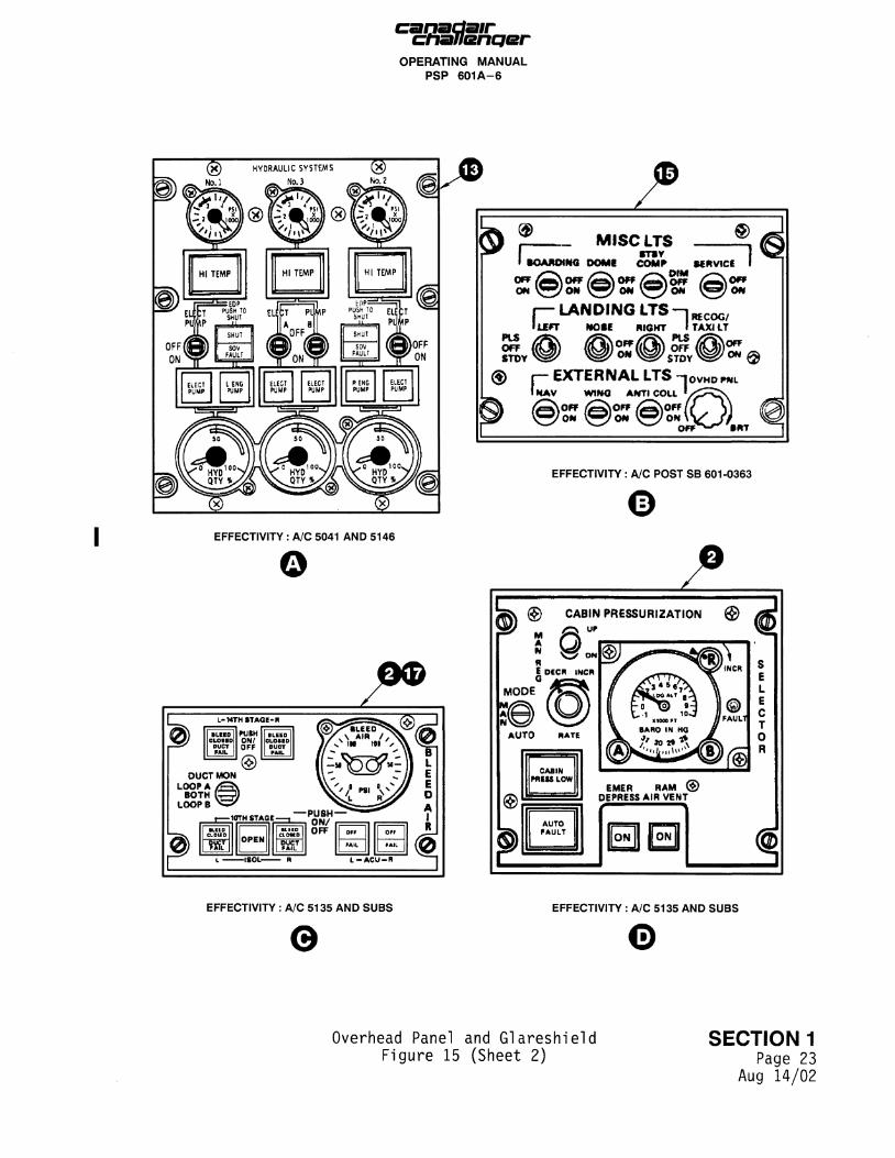
j Overhead Panel and Glareshield S E C T I O N 1 Figure 15 (Sheet 1) Page 22
May 01/96
chaflsriqer OPERATING MANUAL
PSP 6 0 1 A - 6
HI TEMP HI TEMP HI TEMP
&
A ® MISC LTS ® I ROARDING DOMI COMR SERVICE
ON V S ^ O N W ON V ^ / O W I W / O N
PLS OFF STOV
r— LANDING LTS - i II£FT NOtE RIGHT I
RE COG/ TAXI LT
OFF/ ON*
PLS OFF
STDY OFF
® r EXTERNAL LTS -JOVMDFNL I H A V WING ANT1COLL ' x ^ C X 1KAV WtMO ANTI COU
\OFF / f i \ O F F / f i \ O F F OM 'ON ON
OFF •RT
EFFECTIVITY : A/C POST SB 601-0363
EFFECTIVITY : A/C 5041 AND 5146
o
?» L-MTH STAGE'R
WJBH
ON/ OFF
•LEED OLOSID
DUCT I M I L |
OUCT MOM LOOP A /£=N
BOTH K=?J LOOPB > - ^
| M.CEO I CLOUD
\m\\ OPEN
I I BLEEQ I CLOUD OUCT
11 PAH. I
—PUSH ON/ OFF OFF
FAIL I °" I1
1 '*IL 1
z @ CABIN PRESSURIZATION
EFFECTIVITY : A/C 5135 AND SUBS
e EFFECTIVITY : A/C 5135 AND SUBS
G
Overhead Panel and Glareshield SECTION 1 Figure 15 (Sheet 2) page 23
Aug 14/02
canadair chanenqer
OPERATING MANUAL PSP 601A-6
r ©
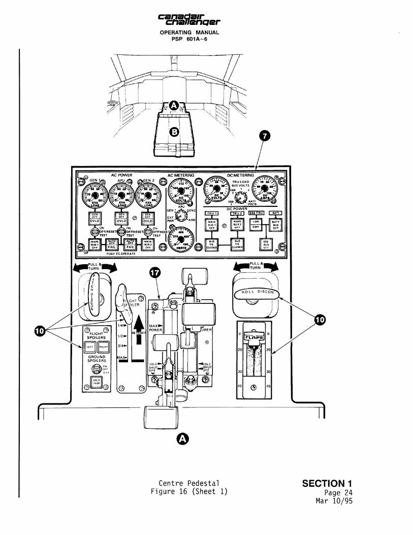
Centre Pedestal SECTION 1 Figure 16 (Sheet 1) Page 24
Mar 10/95
canadair chanencjer OPERATING MANUAL
PSP 601A-6
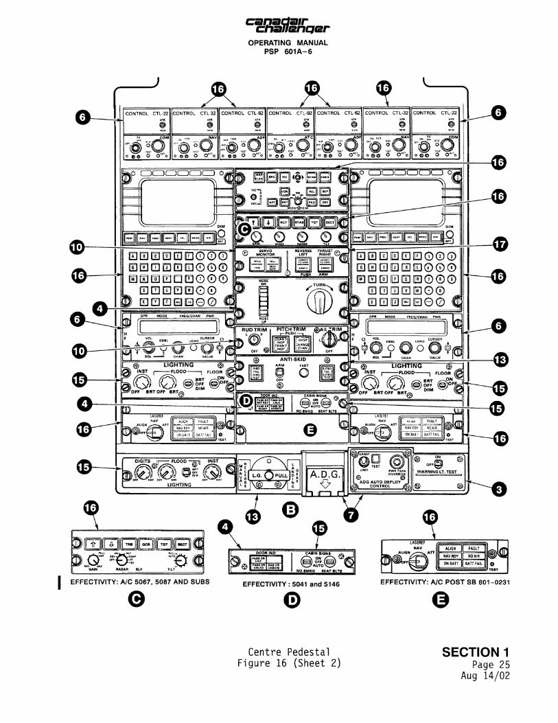
I EFFECTIVITY: A/C 5067, 5087 AND SUBS
e
f LASEREF /
I A U O N / ^ > t ^ ATT | ALIGN |
| NAVRDY |
| ON BAH |
FAULT " |
NO AIR |
BATTFAIL J
. 1 1
mm /TEST J
EFFECTIVITY : 5041 and 5146 EFFECTIVITY: A/C POST SB 601-0231
©
Centre Pedestal SECTION 1 Figure 16 (Sheet 2) Page 25
Aug 14/02
canaclair chaUenqer OPERATING MANUAL
PSP 601A-6
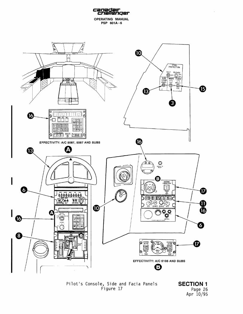
Pi lot 's Console, Side and Facia Panels Figure 17
SECTION 1 Page 26
Apr 10/95
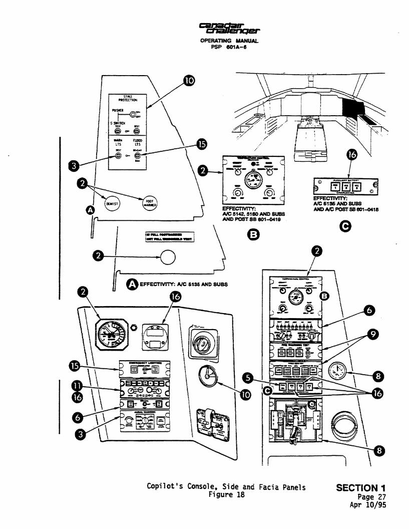
OPERATING MANUAL PSP 601A-6
Copilot's Console, Side and Facia Panels SECTION 1 Figure 18 P a g e 27
Apr 10/95