Embed Size (px)
Citation preview

HOCAPRAZISIONS
Operating Manualfor the
light drop weight tester
ZFG 3000 GPS
ZFG 3000
in accordance with theGerman technical test requirementsfor soil and rock in road construction
TP BF — StB Part B 8.3
Benzstral3e I. 39576 Stendal (Germany)Phone: +49(0) 3931 / 25273 0, far 49(0) 3931 25273 10
PRUFIECHNIK 4
I ___________INSTRUMENTS
www.zorn—ins runicil s c., into a iorn instruments.de
Fwe,,
ZFG 3000 GPS Ir
ZFG 3000

Content
I. Intended purpose2. Preparation for measurement3. Carrying out a measurement3.1 Switching on the device3.2 GPS receiver function*3.3 Starting measurement3.4 Evaluating and printing the results4. Menu4.1 Measuring4.2 Reading maps4.3 Deleting maps4.4 Settings4.5 Setting the clock4.6 Information4.7 Calibration4.8 Firmware update5. Printer6. Care and maintenance6.1 Battery6.2 Care of mechanical loading device6.3 Protection against total discharge6.4 Automatic switch-off when not in use7. Software for ZFG 3000 GPS/ ZFG3000*7.1 Program and hardware installation7.2 Opening the program7.3 Starting the program7.4 Data entry in inspection log7.5 Reading in data from SD card7.6 Usc oC inspection logs produced7.7 Statistical evaluation8. View of the device9. Operating iniormation10./Il ./ 12 Technical datat13. Scope oldeliveryt14. Calibration institutes15. Correlations16. Warranty17. EU conformity declaration
* depending on the equipment and device type(ZFG 3000 without GPS, Software optional)

I.lntcnded purpose
The dynamic plate load test with the help of the ZFG 3000 light drop weight tester is a rapidmethod of determining the dynamic deflection modulus E~j [[MNIm9. This allowsconclusions to be made about the load-bearing capacity and compaction of soils.In accordance with German regulations TP BF-Stb Part 88.3, the procedure can be used onmixed-grained and course-grained soils up to a grain size of maximum 63 mm, loose basecourses, backfill material and for soil improvement. It is used in earth works and roadconstruction, and is well suited for in-house self-control and accurately documenting resultsand preparing reports.
The light drop weight tester can alternatively be used as a static plate load device inaccordance with DIN 18 134, and has the following benefits:- no necessity for a loaded truck as a required counterbalance in the static plate bearing test or
the tripod required for settlement measurement- testing facilities in restricted space, for example during rail track construction, trench
backtilling, for general backfill, in boreholes or other locations with difficult access- low space requirements and low test equipment weight- low time requirements for testing - around 3 minutes for each measuring point
2. PreparatiOn for measurement
To carry out a measurement, place the loading plate firmly and horizontally on the preparedtest area by pushing down and turning. If unevenness is present, compensate for this using drymedium-grain sand which, however, may only fill up any voids under the loading plate. Thesettlement gauge and the loading plate are each fitted with a socket, into which the measuringcable is plugged to connect the devices. Now place the loading device on the loading plateRemove the transport safety device from the drop weight.
it is imperative that the transport safefr device is correcdy engaged to prevent damage
The test area must be pre-loaded with 3 drops. To do this, raise the drop weight and engagethe release mechanism. Once you have aligned the guide rod vertically the drop weight shouldbe released, then raised again using the catch handle after the rebound, and engaged in therelease mechanism once again.

• arryin2 out a measurement.
3.1 Switching the device on
Once pre-loading has been carried out, the settlement gauge should be switched on using the<On/Off> switch. To prevent unintentional switching on of the device, the On/0ff’ buttonmust be pressed for at least two seconds when switching on.
ZFG 3000
We 11.02.0911:58:37
Batt: DZorn Instruments
The current date/time and battery status are displayed. If all data is to be saved to the SD card,please insert the SD card now.
3.2 GPS receiver function*
GPS = Global Position System; used for position-fixingThe OPS module installed as standard receives satellite signals in the open air. Reception is
only available to a limited extent under coverings and in enclosed rooms. The satellite si ‘nalare received by the GPS module to fix the current position. Depending on the satellite si ii.i Istrength, the device requires between 30 and 120 seconds to display the location coordinal’on its display. The location coordinates are now displayed in place of the name ZornInstruments.If no satellite signals can be received (e.g. due to enclosed rooms) measurement and sa iii
can also be carried out without position-fixing.
3.3 Starting measurement:
To start the measurement, press the <OK> button and the following image appears on thedisplay:
Measure 300mrnf 10kgExecute 1st pulse
—1 —
A single acoustic beep acknowledges start of measurement.The test mode currently set is now displayed (e.g. loading plate size and mass of fall weight).It may be necessary to switch this over to the required test mode (see also 4.4 Settings).The second line displays a prompt to carry out the first pulse.Once the first pulse has taken place, the settlement value s is displayed.
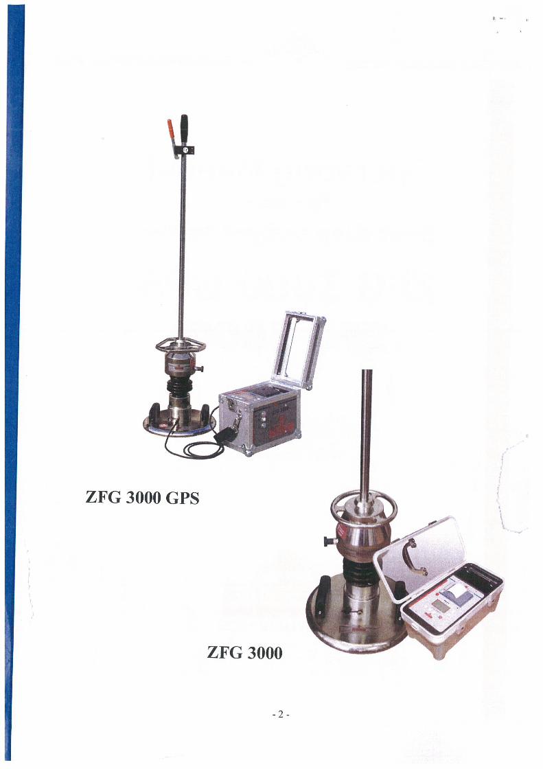
Measure: 300mnVl 0kgExecute 2nd pulse
S~: 0.286 mm
-2-
The beep which follows prompts you to carry out the second pulse.This procedure is repeated up to the 3rd pulse
Measure: 300mnVl 0kgPress <OK>
s~: 0.285 mm52: 0.303 mm53: 0.312 mm
After this, all three settlement values are displayed and this is confirmed with a double beep.The following information is displayed if the GPS signal is missing: <waiting for GPS>All available data is saved after 10 seconds at the latest even if no GPS signal is available. Inthis case, the location coordinates will not be saved to the SD card. The “Press <OK “ promptis displayed in the second line and this then initiates calculation of the results.
3.4 Evaluating and printing the results
The following results are displayed:
52°35.14’ 11 °52.66No: 33 11.03.09 13:22Sm: 0.266 mmsI’s: 2.414E~: 84.59 MN!m2
• geographical coordinates• consecutive number (only if SD card is inserted), date and time• 5m = mean settlement in mm• s/v degree of compactibility, which gives information about whether (he existing
soil can be compacted further or not (in generalS s/v 3 5 soil compactable further; s/v> 3,5 soil NOT compactable more).
• ~ dynamic deflection modulus in MN m2 (MPa).
You must press the Mode button to see the location coordinates, settlement curves andindividual settlement values
52°35.14’ 11 °52.66’
\0,3700.3690,365

After this, you can print the report out by pressing the <&jnf> button.The measurement is completed with OK and a new measurement using the same sequencecan be started with <OK> again.
Iftet the tizecis uttine it is c nnplc’/c, p/cit ~c lit ck ii hether the data has been saved to theSD carct “Read card’ menu c mm md) I/u SI) card must hc deleted he/ore hcing
ii 5cc! fin the first time (“Delete card” ,,ic’nim cOfl?i??(imu/)Ifthc di splcn s/iou s the prompt ‘ ?cq ci t /1 m/ “ a/tci can i ing out a measurement ~iuke thereis a men s tiring ci rot it hi cli mmia~ hai c hc cm mus ‘d Jo, evample i/the fall ii eight u asengaged too firm/v 1/ thc. san c e /0? inc S sag appcars a/ta’ the pulse iv repeated then thevail is too so/i (i 4 000 nun s 01 s 6) nun) the at ce/em aflon scnco; is de/eet,vc, there acontact problem in one ofthe plugs vi thu e is ci hrokcn cable In these caves, inca ureinenta sing the drop weight te.ste, cannot hc tout tm/cc!
4. Menu
If you press the <Mode> button, you can call up additional device functions. Use the <Okbutton to confirm the menu command selected.Quit the menu by pressing the <On/Off> button.
4.1 Measuring
sec 2. and 3.
4.2 Read card (display data saved to SD card)
• Select the View card menu command in the menu (see 4.).• Select the saved individual measurements with consecutive number using (he or
<-> buttons• The display first shows the consecutive number for the measurement you have
selected, the total number of saved measurements, date and time for saved individualmeasurements in addition to the mean settlement, s/v and Evd values.
• llyou press the <Mode> button, the second display shows the associated coordinatesif these were available for this individual measurement. In addition, you can see thesettlement curves and the three individual settlements.
• You can use the <Print> button to print out the report afterwards.
4.3 Delete card
• Select the Delete card menu command in the menu.• The number of saved individual measurements is displayed in the second line Contain
data. This menu command enables you to delete all individual measurements in onestep.

•--
a‘~
•.
.)‘~
..
.•
Ict
I~I-,
‘~IE
rAi
l~
3~
;~
cni9
e~
-~D
H~
t<
t<
cn
~
0Z
cv‘<
~~
~o~
0z~
00
00
0zg
~~
~o
00
0—
CI—
C”
0—
~D
Z’<
Z~
cvD
z0
—~
(~
0CD
~‘-<~~
Q~~
O~
~A
z-o~
,~
Acv~
~‘
‘4,~
~z~
0o
ifl~
00
—,
——
0-—
.—
~~
<-.
-‘~
~A
0~
,0t
r.
Cv—
%UQ
00
o0~
uQ
0~
rZ
z~
cvco~
.~
(tc,.
-*
-~-~
•a—
to
~0
o0
-~
-cv
cv‘~
-‘~
v0-
,
~~
:i -*
30
<~
00
V_
0-o
~-
a-:
a-~
cv.-
t~
00
005
~z
z-—
—3
0-C
’~Q
~3
OpO
~~
A~
S—
--•
~0
t~
0Z
0-
uQ
~,
0~
cn0~
~~
OQzo
o—
0-a
-,
z—
~C
”~
~&
GQ
°0
~~
0t<
fl~
.0
t~
0-cv
A0-
_z_
‘-~
UQ0
~-,
s~0
~0
0~
$d
D~
1“
~_
~-÷~
<-.
C
;0
Ce
\
0-C
)0
0~
‘~
00
Z~
D~
~Q
03
~,0
~C
~0
—0
WO
QCI)a,~
~.
tn~
4,
0~
—.
—z0~
-0
0~~
-~
-~
0~•
~:;~
~C
et
—.
05
0A
DO
Z0-
0-0
00~
o0
-0
-~
~—
~~
-
~~
~0
QO
UP
Z~
-,g
~a~
o~
—’
C0~
’-i
—Z
A~
0-
00
2?
9t
io
za
‘<0
00
~~
C(1
2C
0-
—0
-DZ
—~
C0a-
~C)
Oo
~~
<_
a~
g-o
c~—
.
a-0
-C
M-,
0(1
~~
0(IC
?0
-0
-Cv
—P
)r~
CbtI
C0
~•+
0
0-0
0p4
,0
~0
O0~
a-~
0-
(12
~0
~~
0-
C)—
p4’
+o
0—
00
-CD
00
—0
CD~
—i-.-
za
÷-~
0-
0-
z-0
0a

4.8 Firmware update
Firmware can only be updated on the mmiii It rei~s suggestion.
5. Printer
The printer integrated in the device is a thermal printer. This only requires thennal paper forprinting.To change the thermal paper roll, open the printer compartment by pulling the accessdepression upwards.Take the empty thermal paper roll out and replace it with a full one. When replacing thethermal paper roll, please ensure that the lull thermal paper roll is inserted with the side to beunwound facing to the left and downwards! (Figure 5.1). When inserting, place the start ofthe roll top left above the printer tear-oil edge.
After this, close the printer compartment by pressing it down.
If the thermal printer does not print after the thermal paper roll hasbeen replaced, this has either been inserted incorrectly or it is not athermal paper roll.
6. Care and maintenance
6.1 Care of mechanical loading deviceThe mechanical loading device must be cleaned of any dirt adhering after use using a drycloth. The chrome-plated guide rod must not be greased. Heavy soiling must be removedusing spirit or kerosene. The drop weight tester must be carefully stored during transport, andthe fill height must be checked at regular intervals. The correct fall height is stated on thecalibration report and on the calibration nameplate on the fall weight.
6.2 BatteryCareful care of the battery ensures permanent readiness for use of the drop weight tester. TheNiMFI battery fitted should only be recharged from time to time using the power supplyprovided. The charging status can be seen on the charging bar in the display. The chargingprocess is normally complete after around four hours depending on the battery state. If thebattery has not been used for a long time it is important that it is recharged, so thatmeasurements on site do not need to be discontinued due to an empty battery.
6.3 Protection against total dischargeThe measuring device is fitted with total discharge protection for the battery. The battery isswitched off shortly before total discharge. After this, the settlement gauge can no longer beswitched on. If the battery charger is connected the battery will be charged and the device canbe used after around for hours.
6.4 Automatic switch-off when not in u~e
Fig. 5.1
The settlement gauge switches itwl oIl 4 minutes after the last button was pressed.

4.8 Firmware update
Firmware can only be updated on the In.IIuhlnuLIrers suggestion.
5. Printer
The printer integrated in the device is a thermal printer. This only requires thermal paper forprinting.To change the thermal paper roll, open (he pnnter compartment by pulling the accessdepression upwards.Take the empty thermal paper roll out and replace it with a full one. When replacing thethermal paper roll, please ensure that the full thermal paper roll is inserted with the side to beunwound facing to the left and downwards! (Figure 5.1). When inserting, place the start ofthe roll top left above the printer tear-off edge.
After this, close the printer compartment by pressing it down.
If the thermal printer does not print after the thermal paper roll hasbeen replaced, this has either been inserted incorrectly or it is not athermal paper roll.
6. Care and maintenance
6.1 Care of mechanical loading deviceThe mechanical loading device must be cleaned of any dirt adhering after use using a drycloth. The chrome-plated guide rod must not be greased. Heavy soiling must he removedusing spirit or kerosene. The drop weight tester must be carefully stored during transport. undthe fall height must be checked at regular intervals. The correct fall height is stated on thecalibration report and on the calibration nameplate on the fall weight.
6.2 BatteryCareful care of the battery ensures permanent readiness for use of the drop weight tester. 11wNiMl-l battery fitted should only be recharged from time to time using the power supplyprovided. [be charging status can be seen on the charging bar in the display. The chargingprocess is normally complete after around four hours depending on the battery state. If thebattery has not been used for a long time it is important that it is recharged, so thatmeasurements on site do not need to be discontinued due to an empty battery.
6.3 Protection against total dischargeThe measuring device is fitted with total discharge protection for the battery. The battery isswitched off shortly before total discharge. After this, the settlement gauge can no longer beswitched on. If the battery charger is connected the battery will be charged and the device canbe used after around for hours.
6.4 Automatic switch-off when not in useThe settlement gauge switches itselfoil 4 minu~.s ‘ilter the last button was pressed.
Fig. 5.1
7. Software for ZFG 3000*
7.1 Program and hardware installation• Windows XP or newer Windows operating system, broadband Internet connection in
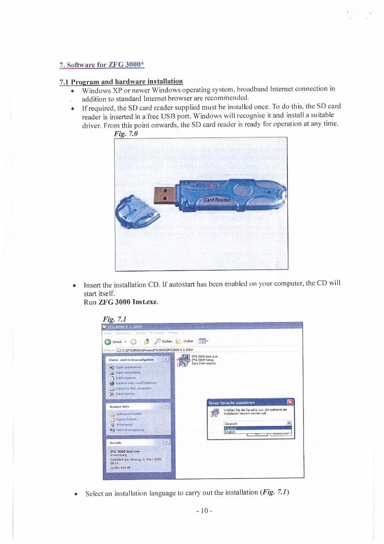
addition to standard Internet browser are recommended.• If required, the SD card reader supplied must be installed once. To do this, the SD card
reader is inserted in a free USB port. Windows will recognise it and install a suitabledriver. From this point onwards, the SD card reader is ready for operation at any time.
Fig. 7.0
I ~
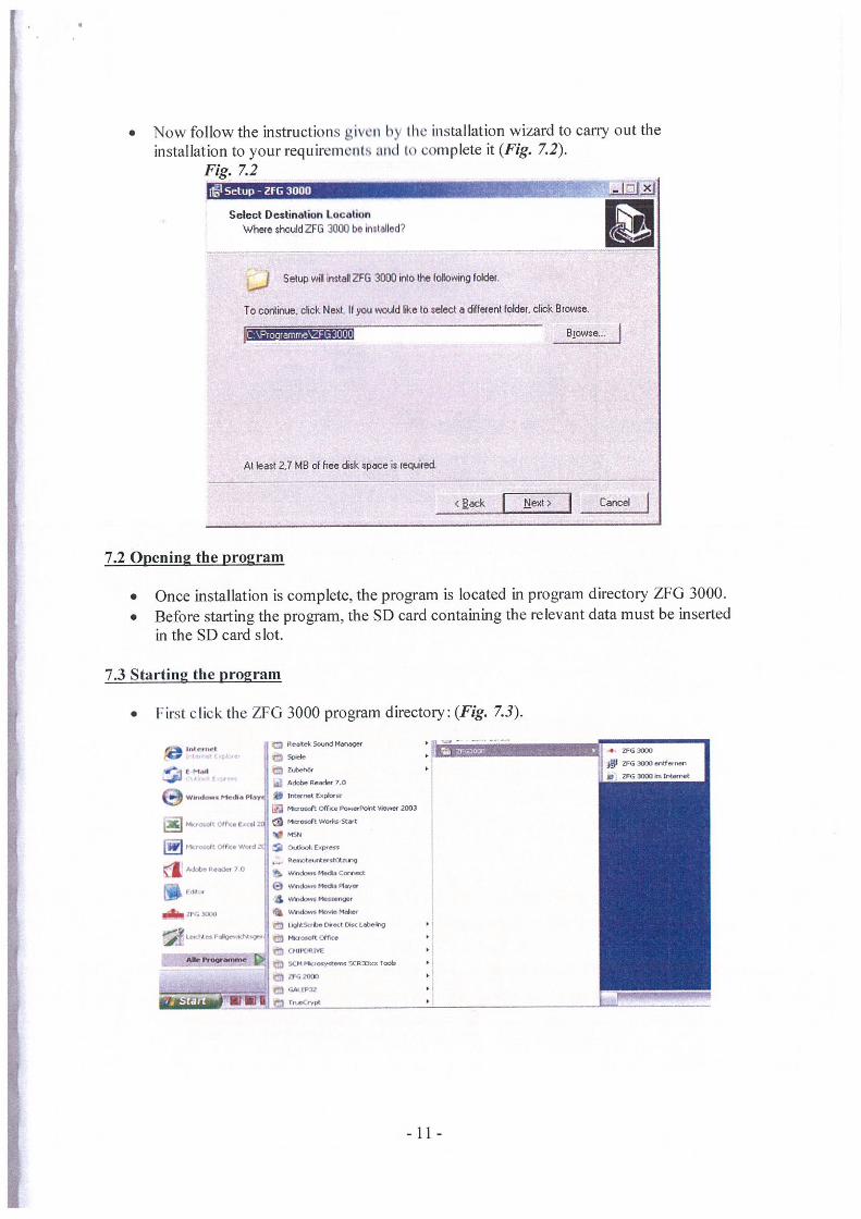
• Insert the installation CD If autostart has been enabled on your computer, the CD willstart itse If.Run ZIG 3000 Instexe.
Fig. 7.1
Zt.ixk • S4Jchen Ordnet
z~zrc3~n~s.ftwnzFq3000gFG~ 9 32009
JI~l Z~G Int.xea.t.,- — o.dneadgaba. ~
inc Zv.n’nsbnr8s
~D*a~.Wth,FeW4n*t.wl
C
*ndnt Oqle.~fJ1 WIN., S.. a. Spc.&. an. de wth.a.d de’
5QltweeWG~ ~J~S5’ Imtabnor, b.n.Azt ,q..d.n ..L
F-., 0~
g Debee~ OSUItCI,
~ bn&mo E
a
Inst.’..
1i 94mflg, 0. lIla ~9,06:14
• Select an installation language to carry out the installation (Fig. 7.1)
-10-
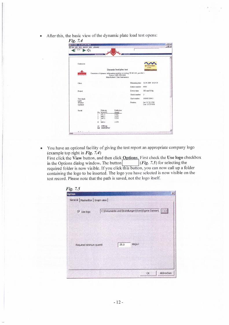
• Now follow the instructions givea y the installation wizard to carry out theinstallation to your requirenielit% and to complete it (Fig. 7.2).
Fig. 7.2fit -
Select Destination tocationWhere should ZFG 3000 be installed
Setup wil install ZFG 3000 flo the blowing bolder
To ccrirue. click Next. II you would I~e to select a different folder. click Srowse.
L:\P~arnrrie~ZFG3Q’JO Biowsa..
sack Li~i!~J Cancel
At least 2.7 MB of free disk space is requred
7.2 Openin2 the program
• Once installation is complete, the program is located in program directory ZFG 3000.• Before starting the program, the SD card containing the relevant data must be inserted
in the SD card slot.
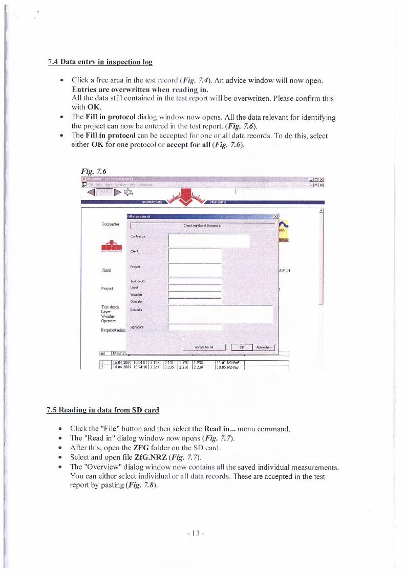
7.3 Starting the program
• I ir’il click thc ZFG 3000 program directory: (Fig. 7.3).
t.n.t Petea Scoid Mooer- V(q.reti.r.., ~
(Mad C~ C.aln4 t~Ut.. ~ Adthe feader 7.0
9 wind..... Med.. ‘lay S i.—net E.piot.tWI *aOSO& Cf C. Pc...rPtint V*~.a 20W
ikfa~dL Of (Ic. ~ai. ~ we.soIt Woda-stwt
•ktoOcdt Out. Wo.d. 0.RbdSx~e.P
Peotc.s*eshrn.gA.kt P..jo. 7 0 ~ wnic.. i.a. c..w..co
~a —~
4?G ,aJo MOM. woes~ LI~t5ot.. fliact 01c i.ab.fr.g
Le.uf#sPao.tht.o.. ~ ~.s.sdt Office
CFIill7(ItlEPtaot~rmw ~ SCM ~tews SCRflc. Took
JTGZ0W
• ~CstP~z
‘w.CtypO
Zn
Zn 20W ~ttFetntn
W Zn 30W ft W*.i.t
• After this, the basic view of the dynamic plate load test opens:Fig. 7.4
tb Ca ~ b~ Lão.~.. —
C—
Dyn.dc load pl.4. tat
Don,. of 4~c.at d.IWmia mamas a.ma* TV OF 5.01t1Dt?a tWO 2~G0l00
t.ta Zo~. bnatj
Mmnn.pii. 16042000 102410
Do,.. ..nsbe 4000
Domai~p. )~3m&10kg
Taideth Ca,4ma*m 40400100401lam
box. Is 5P12 740Qpaa.. L..lr210306
0a~a ~kt..4y OtOot..t~, ~nyw.I 4~I 5122 03 22353 71 7206
O 04 0212
— am—IN I0MI00~.~
-J
• You have an optional facility of giving the test report an appropriate company logo(example top right in Fig. 7.4)First click the View button, and then click Options. First check the Use logo checkboxin the Options dialog window. The button ________ (Fig. 7.5) for selecting therequired folder is now visible. If you click this button, you can now call up a foldercontaining the logo to be inserted. The logo you have selected is now visible on thetest record. Please note that the path is saved, not the logo itself
Fig. 7.5x
General r’lake&or Gr.ph view
P Us, bgo I C*kneo*e Ln~ n~5ven~igene D&ebs~ [~)
Requfredrrirrimqua1ti 25.0 t’TQm’
°~ I~~I
7.4 Data entry in inspection log
• Click a free area in the test record (Hg. 7.4). An advice window will now open.Entries are overwritten when rending in.All the data still contained in the test report will be overwritten. Please confirm thiswith OK.
• The Fill in protocol dialog window now opens. All the data relevant for identi~ingthe project can now be entered in the test rcport. (Fig. 7.6).
• The Fill in protocol can be accepted for one or all data records. To do this, selecteither OK for one protocol or accept for all (Fig. 7.6).
Fig. 7.6
I 16042009 100401 2123 2121 1570 1938 IIóI8tUnt2 16.042009 102420 2267 2235 2216 2239 I0.OSKtThc’
7.5 Reading in data from SD card
• Click the “File” button and then select the Read in... menu command.• The “Read in” dialog window now opens (Fig. 7.7).• After this, open the ZFG folder on the SD card.• Select and open file ZfG.NRZ (Fig. 7.7).• The “Overview” dialog window now contains all the saved individual measurements.
You can either select individual or all data records. These are accepted in the testreport by pasting (Fig. 7.8).
<I
Counctor
a1Ql2~i
O,eck~.,tor 6 D*e,t 6
‘C
IA
Project
Tot dord,
to
0~~
M01
T~t depthLayec
Opualor
Requortd n
lou IM..ew.II
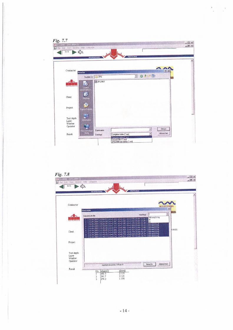
Fig. 7.7
Test depthLayaWMth&Op~ator
‘C
3JftJ4I
~.
Contncloe
SuE,n
42sa2
Project
Test depthI-ay&Weather.Dpaator
0~ IDate tc~T*t01r1Y4 2!
I°~~nI
Fig. 7.8
iGt~ 0~
oak, Ne
Project
0401
RestiltI mat dd&aSetS9fTtSfl9 FWidIfl I gt,.dwa
It moVeI 032 173 274.2
s non21232121I 570
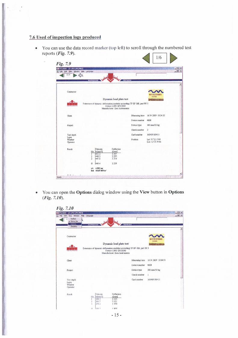
7.6 Used of inspection 1025 produced
• You can use the data record iii irk (lop left) to scroll through the numbered testreports (Fig. 7.9).
16Fig. 7.9
tb 0* 6.~.S. 004 w*
CodncLor
Ior’oDynamic load plato tool
Ddan.nc D(~mmc deformohon moö*.’. SCC0t~3g TP OF008, pal St 3C’cnce LWD ~C3%0
Mros~cms~ Zorn Insnnmos
tree 6042009 ‘02420
De~icernbu 40%
Project Deocetype 300umitlOIcg
Chockeonber 3
Tosodqth C&darobu 160409000411IayaWaite Ponitee Lao 5I’22 740Opecalor Lea 1225 9306
Ddectic..tie frto~m’sI 4nm,l0 14502 22672 l44~.3 2 23514478 1216
0 4494 2239
ak54 1096 MNO&
~19-,
• You can open the Options dialog window using the View button in Options(Fig. 7.10).
Fig. 7.10a tSr’ 04IW 0* —
.4r— I— Sr
__‘a
Cotincte
Dynamic load plate test
Dowr.ioe or~aaac defornat.a moats accodiig TP SF000. — 50.3Denier OVID ~G3000
Maw&caxa’ Zen. l,,lnmaIs
Matmtg lane 16042009 000400
Device oomibu 4000
Prviccl Dntceoype 300rmiaflOkg
Check cantor I
Tc,Id.ylh Cedranbor 160409109411L.aynWeaIhn
Rn’.h Vdoc.Oy DetectonlIe L*m~flI or.n’nl0 3403 2023
3407 21214 0570
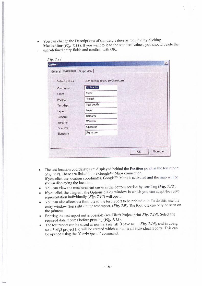
• You can change the Descriptions of standard values as required by clickingMaskeditor (Fig. 7.11). If you want to load the standard values, you should delete theuser-defined entry fields and confirm with OK.
Fig. 7.11x
General Maskethtor Graph view
DeFault values user deFined (max, 31) Characters)
tractor
lient Client
Protect Project
Test depth Test depth
Layer Layer
Remarks Remarks
Weather WeatherOperator Operator
Signature Signature
I o~ Abbrechen
• The test location coordinates are displayed behind the Position point in (lie test report(Fig. 7.9). These are linked to the GoogleTM Maps connec(ion.If you click the location coordinates, GoogleTM Maps is activated and (lie map will heshown displaying the location.
• You can view the measurement curve in the bottom section by scrolling (Fig. 7.12).• lfyou click the diagram, the Options dialog window in which you can adapt the curve
representation individually (Fig. 7.13) will open.• You can also allocate a footnote to the test report to be printed out. To do this, use the
entry window (top right) in the test report. (Fig. 7.9). The footnote can only be seen onthe printout.
• Printing the test report out is possible (see File4Project print Fig. 7.14). Select therequired data records before printing (Fig. 7.15).
• The test report can be saved as normal (see file-*Save as ... Fig. 7.14), and in doingso a t.zfg3 project file will be created which contains all individual reports. This canbe opened using the ‘file-*Open...” command.
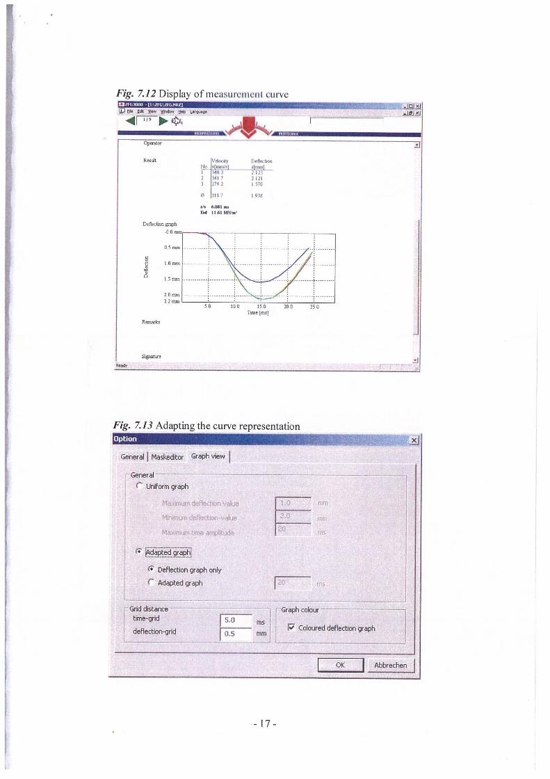
Fig. 7.12 Display of measurciuclic curve
a W&w tM’ —ir~ ~op~.lor
Res&
Fig. 7.13 Adapting the curve representation
General Maskeditor Q~aph view
GeneralC Urtorni graph
fl Deflection graph only _________
C Adapted graph I
Gild distance ______ Graph cobstime-grid 5.0
deflection-grid o.s mm P Colosed deflection graph
OK P~I~i’ec1,en
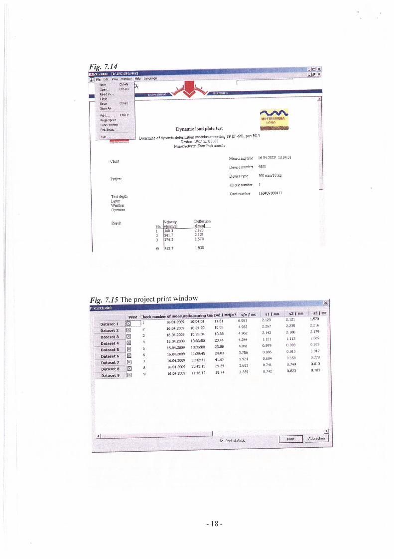
Fig. 7.14po a van M*n 1*
— tb++N0p83 ~R*d In,,
s~. tbitS1—As,
pinpro—pntP,t.Wpet ld.a
Ca
Project
Test 6~lh
WnIIiuopesatot
Rota
Dynamic load plate lestrIc
aJ~J.3J
Chin
wu$ThZPWA
Dstaoiae ofdynarác defonnalion modulus accorduig TP OF-SIB, part 083Demte LWD 7103080
Mesoufacufl Zom Instnuoeas
Mcastirmgliffle 16042009 10 04.61
Deuce numbor 4000
De’nce type 300 mis/I0 kg
Ch~kmn1bu I
Cardmsnbu 160409t00411
Iwdocty DeRecIáOIl
I 3403 2.1232 3407 21213 2742 0570
0 3187 1938
Fig. 7.15 The project print window
of ...~1se.ba~ac tI.EvdI PGl$.~1 afvJ .a
OS I
Dades.t 2
Das.tS
Da.e& 4
Dasat SDateset 6
Datasat 7
Datasat 8
Datasot 9
I~l
S
I 06.04,20)9
2 06.04 2039
3 t6,04.2039
4 16.01.2039
$ 06.04.2039
6 56.04.2039
7 16.04.2039
8 06.04.20)9
9 26.04,20)9
10:04:01
10:24:20
00:26:34
00:33:50
I0:$5:~
00:39:45
11:42:41
11:43:15lt:46:l7
11-61
10.05
00-38
20.44
23.83
24,83
41.67
29,34
28.74
6.831
4 982
4 962
4.244
4.041
3756
3.924
3,603
3.339
at $ S2.123
2.267
2142
1,121
0.979
0.604
0,740
2.120
2 235
2 183
1112
0988
0.91$
0.158
0.749
0.823
‘3’—1.570
2.216
2 79
l.~9
0.959
0.907
0 779
0.810
0.783
_____ ±1I Pot*JAb&eáeflj
II I1 PntstetIstIc

Tech depthLay~W~th~t~tiLor
VdaciLy DeflectionI-4o l.4mnVsi i[o.ni
I 0c.n
7.7 Statistical evaluation
All the test results are displayed colleciively and are subject to a statistical evaluation in thestatistics view. Depending on the minimum quanule entered (Fig. 7.5), the arithmetical meanvalues of the random sample, Ihe standaid deviation, the variation coefficient and the qualitynumber are calculated. The test result is only produced after this.
• As a basic principle, all individual measurements are taken over into a project(statistics).We therefore recommend that you select the required individual measurements beforereading the data from the SD card (see Chapter 7.5). Select the required individualmeasurements (Fig. 7.8).
• Once individual measurements have been selected (see Chapter 7.4), the necessarydata must be incorporated. The test reports resulting are numbered and can be calledup using the data record marker (see Chapter 7.6). If additional/not all test reportsneed to be incorporated into the statistical evaluation, individual reports can be addedor deleted in advance. To do this, click the Edit button and then Add Datasets/DeleteDataset (Fig. 7.16).
• You can open the Options dialog window using the View button in Options. Youshould enter the required minimum quantile in the entry window under General(Fig. 7.5).
• To start acceptance of individual settlements in the statistics, click the Statistical viei~activated / deactivated button (top left) (Fig. 7.9).
• The test result is determined after this and is displayed in the lower section.• The statistics can be saved and printed out (see Chapter 7.6).
Fig. 7.16 Add dataset/Delete datasetOI,GJOOU tIG~eFG..IU~ x~ Fl. e* ~.,. V~~da, H*.~t.vi.
I ~_. L-~AaeD~’.’V~5
Conhactar
5a Dynamic load plate testDcoawaoe at dyoaomc defoermiton mo&to occordthg TP ar-se. FQOI DO 3Device: LWD Z103000
Monufaciorec Zoni Ioolnjxnmos
ClimE
Projoco
Meaouringtuoo 06042089 1004.01
Dencentimbe 4000
Dnoceeype 300nmVIUk~
Check noonbec I
Cardnwnbu 160409080410
I 34032 34073 27.12
31332121I 570
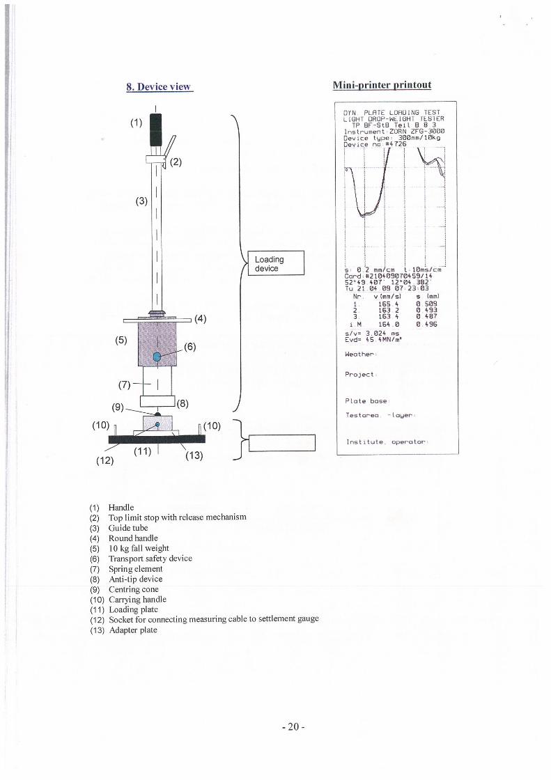
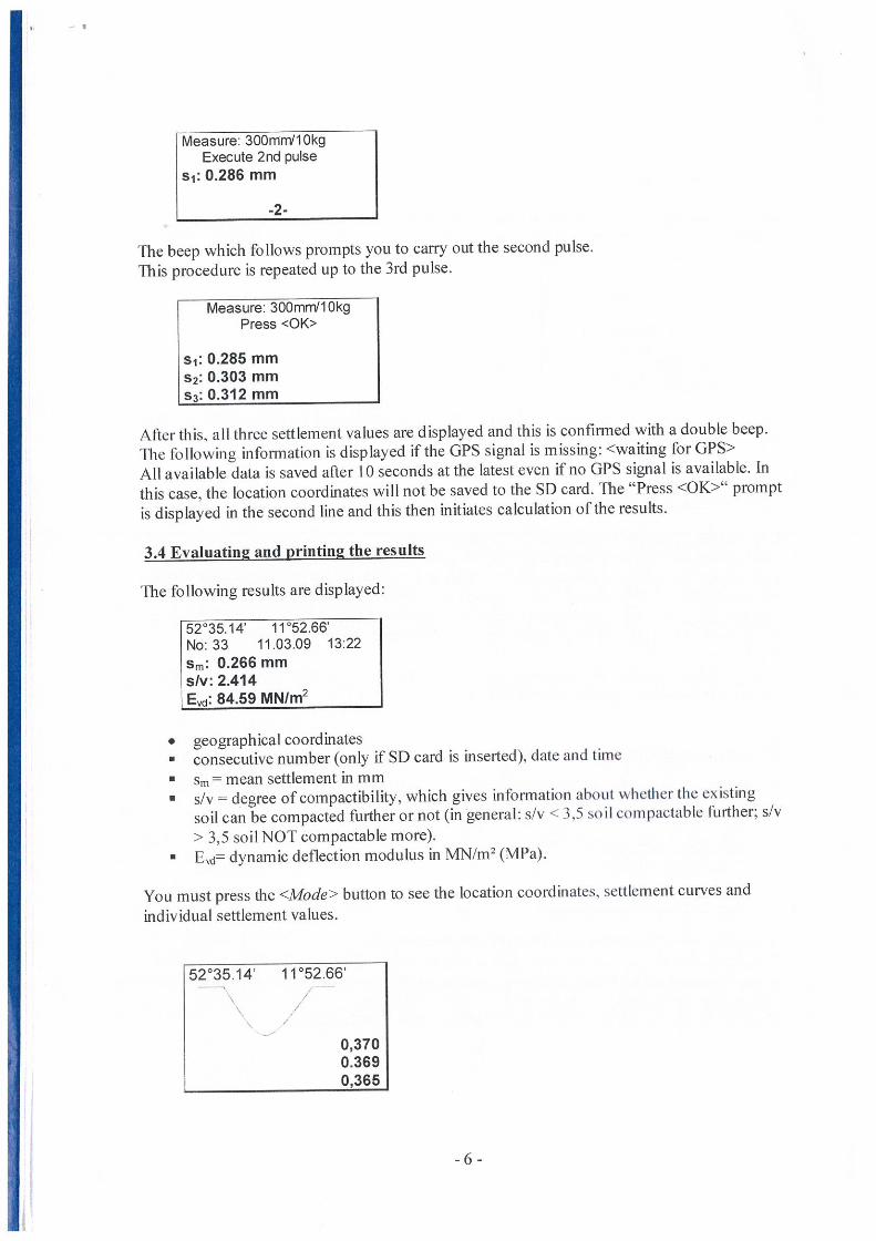
8. Device view Mini-printer printout
DIN PLATE LOHIJINS TESTLIGHT ORL]P-i~1LIGH1 FLS1CR
TP Br-ste TeAt 8 8 3Instrument ZORN ZF63060Device type 300mm/lOkgDevice no *4726
s S 2 mm/cm t lOms/cmCard *210409070459/1452’49 407 1204 382Tu 21 04 69 07 23 03
Nr’ v (mm/si s immI1 1654 05092 1632 04933 1634 0487
iM 1640 0496s/v 3 024 msEvd 45 4MN/m~
Weather
(1)
(2)
(3)
(5)
(7)
(9)
(10)
Project
PLate base
Testor’ea Lower
Institute operator
0) _____
(12)
(1) Handle(2) Top limit stop with release mechanism(3) Guide tube(4) Round handle(5) 10 kg fall weight(6) Transport safety device(7) Spring element(8) Anti-tip device(9) Centring cone(10) Carrying handle(11) Loading plate(12) Socket for connecting measuring cable to settlement gauge(13) Adapter plate

9. Instructions for engapin2 fall weight
When engaging the fall weight in the re euse mechanism, please use both thumbs as showii inthe sketch.
The fall weight is lifted up as far as possible with both hands until shortly underneath the limitstop so that it can be pressed into the stop using both thumbs as shown in the sketch. Use yourthumbs to lift the fall weight up slowly until it engages in the release mechanism.This avoids engaging the weight too harshly, which can lead to faulty measurements.
10. Technical data for mechanical loading deviceMass of fall weight
Total weight of guide rod including spring unit consisting of discsprings, fall weight transport safety device, release mechanismand anti-tip device.
Maximum pulse force (calibrated)
Pulse duration
(Data in brackets relates to options which can be supplied)
11. Technical data for loadin2 plate and CBR stamp
10kg (15 kg)
5 kg
707 kN
17 ms
Diameter of replaceable loading plate depending on option ordered 300 mm (150 mm)
Diameter of CBR stamp (50 mm)
Mass of loading plate or CBR stamp including release mechanism housing, 15kgsensors and 2 carrying handles
(Data in brackets relates to options which can be supplied
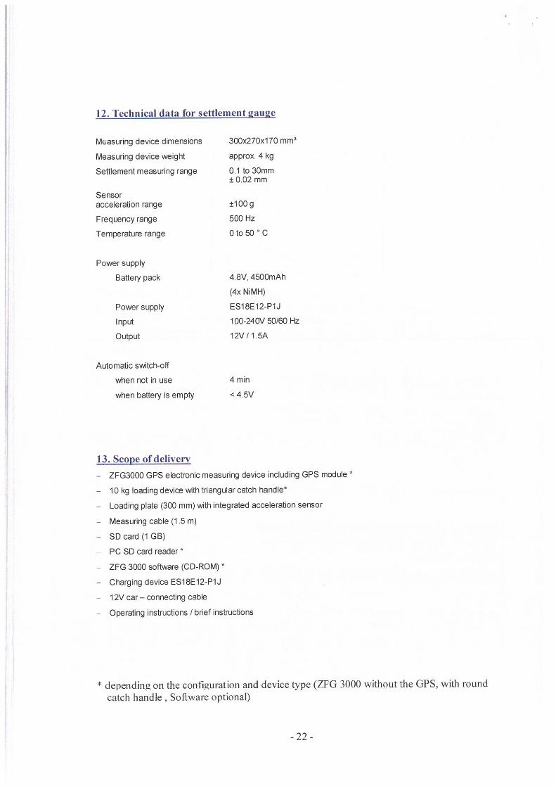
12. Technical data for settlement gauge
Measuring device dimensions 300x270x170 mm3
Measuring device weight approx 4 kg
Settlement measuring range 0 ito 30mm± 002mm
Sensoracceleration range ±lOOg
Freqiency range 500 Hz
Temperature range 0 to 50 C
Power supply
Battery pack 4.8V, 4SOOmAh
(4x NiMR)
Power supply ES18E12-P1J
Input 100-240V 50/60 Hz
Output 12V/i5A
Automatic switch-off
when not in use 4 mm
when battery is empty <4 5V
13. Sco e of deliveryZFG3000 GPS electronic measuring de~ce including GPS module
10kg loading device with triangular catch handle*
Loading plate (300 mm) with integrated acceleration sensor
Measuring cable (1.5 m)
SD card (1 GB)
PC SD card reader *
ZFG 3000 software (CD-ROM) *
Charging device E518E12-P1J
1 2V car — connecting cable
Operating instructions / bnef instructions
* depending on the configuration and device type (ZFG 3000 without the GPS, with round
catch handle Software optional)
-22-

14 Calibration institutes for drop weiuh( (ester
ZORN INSTRUMENThHOCFIPRAZISIONS PRUFTECHNIIc
Kalibrierste lieBenzstr. ID-39576 StendalTel.: +49(0) 3931 I 25273-0, fax: +49(0) 3931 / 25273-10, mailto: [email protected]
Please visit the BAST homepage for more calibration institutes:http:/ www.bast.delhttp: www.bast.de/htdocs/qualitaetlp-steiie/tp-bf.htm

15. Correlations - for information only, no guarantee of intlirmation correctnessOuote from German ZTVE STB 94, Research Institutt for Road md Traffic (2005addition)
3.4.7.2 Requirements for deflection modulus
The information provided below is based on the 10% minimum quantile.When constructing roads of Construction Classes SV and Ito IV on frost-protected substrate or substructure, thefollowing deflection modulus of at least
E~ 120 MN/rn2 or alternatively E~d 65 MN mand for Construction Classes V and VI a deflection modulus of at least
E, 100 MN/rn2 or alternatively E~a 50 MN m2Ev2 = 100 MN/rn2 or alternatively Evd = 50 MN/m2is necessaryThe deflection modulus E~2 is to be verified in accordance with a static plate load test in accordancewith DIN 18134 and the deflection module E~d with a dynamic plate load test in accordance with TPBFPart B8.3.Once these requirements have been able to be fulfilled by compaction of the layers to be constructedabove the formation, it is sufficient to achieve a deflection modulus of at least
£ 2 100 MN m’ or alternatively E~ 50 MN m2andfor Constmction Classes V and Via deflection modzdus ofat least
£ 80 MN m2 or alternatively £ 40 MN m2in the case of Construction Classes SV and Ito IV through the use of separate verificationIn the case of frost-sensitive substrate or substructure, a deflection modulus of at least
E 45 MN m2 or alternatively E~d— 25 MN/rn2Ev2 = 100 MN/m2 or alternatively Evd 50 MN/n?is necessaryis required on the formation If the specifications do not speci~’ whether the static or dynamicdeflection modulus must be verified for cases stated in this section, verification should &ways takeplace using the static deflection modulusAs an altemafive, calibration of the dynamic deflection modulus on the static deflection modulus inaccordance vAth TPBF Part E4 can take place, and then the dynamic deflection modulus can be usedas a requirement.if the required deflection modulus cannot be achieved on the formation through compaction either(1) the substrate or substructure must be improved or consolidated or(2) the thickness of the loose base courses must be increasedThese measures must be stated in the specifications
Section 14.2.5:
Table & Guide value for correlation of static deflection modulus E~ or dynamic deflectionmodulus E~ to compaction ratio Dpr for coue’se-grained soils groups
Soils group Static deflectiorF Dynamic deflection Compaction ratiomodulus E~2 in MN/rn2 modulus E~ in MN/m2 Dpr in %
GW,Gl ≥120 ≥65 ≥103≥100 ≥50 ≥100≥ 80 ≥40 ≥ 98≥ 70 ≥30 ≥ 97
GE, SE, SW,SI ≥ 80 ≥ 50 ≥ 100≥ 70 ≥40 ≥ 98≥60 ≥35 ≥97
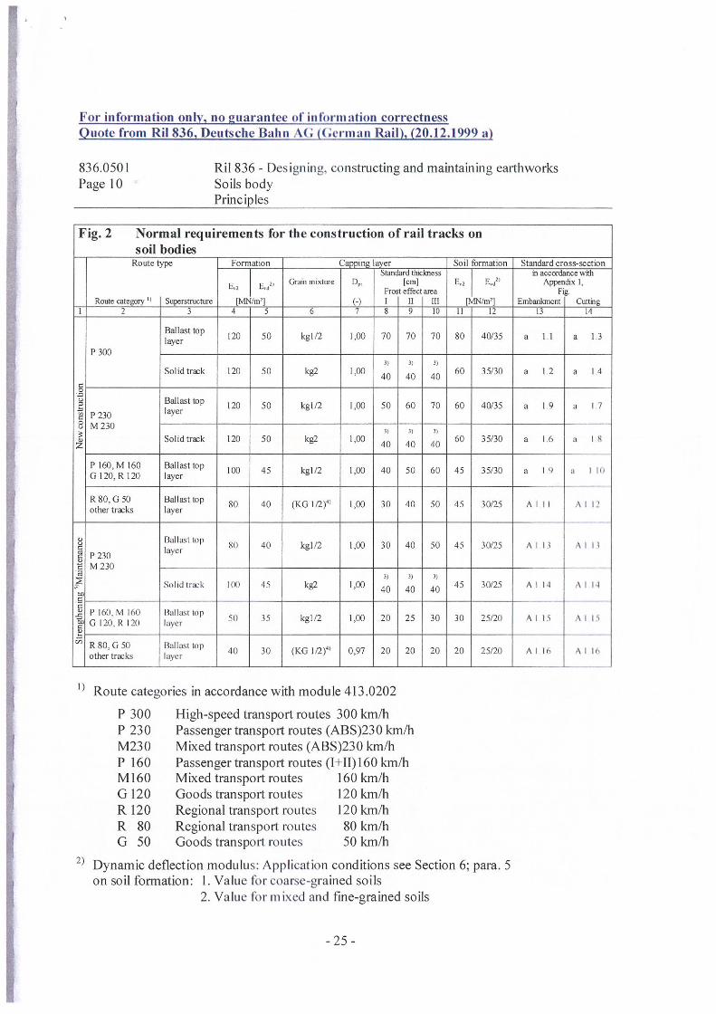
For information only, no guarantee ol inlormation correctnessuote from Ru 836 Deutsche Bahn At. Germ an Rail 20.12.1999 a
836.0501 Ril 836 - Desi ‘nan ‘ constructing and maintaining earthworksPage I 0 Soils body
Principles
Fig. 2 Normal requirements for the construction of rail tracks onsoil_bodies
Route type Formation Soil formation Stamiard cross-sectionStandard thickness I ü, accorthnce wth
Grain mixture op. [cm] I E,~” Appendix I,Ei Ed2’ Fr~t e~ct ~a Fig
Route categoty” Superstnicturc [MNIm2I (.) I II III (MN/rn’] Embanimieni CunligI 2 3 ~T 6 imr9vm 12 13 14
Ballast top 120 50 kgl/2 1,00 70 70 70 80 40/35 a I I a 13layer
P3003) 3) 3)
Solidtrazk 120 50 kg2 1,00 40 40 40 60 35/30 a 12 a 14~C,=~ Ballasttop 120 50 kgl/2 1,00 50 60 70 60 4Q/35 a 19 a 17
~ P 230 layerS M230~ 31 3) 3)0~ Solidtrazk 120 50 k82 1,00 40 40 40 60 35/30 a 16 1 8
P160,MI60 Ballasttop 100 45 lcgl/2 1,00 40 50 60 45 35/30 a IL) a lI~lG120,R120 layer
R80,G50 Ballasttop 80 40 (KGI,2)4’ 1,00 30 40 50 45 30/25 AIlI All’other tra~ks layer
0 Ballasilop 80 40 kgl/2 1,00 30 40 50 45 30/25 Al Il SIll~~ P230 layer~ M230 — — — —a
~ Sol,dtr~rk III) 45 kg2 1,00 40 40 40 45 30/25 Al 4 I II
~ — -~ —
U P 60, M 16(1 Ballast lop 50 35 kgl/2 1,00 20 25 30 30 25/20 A I Ii A I I
~ G 120 R 12(1 layer~‘~ R80,G 50 Ballast top 40 30 (KG li2)~ 0,97 20 20 20 20 25/20 Al l~ ~ I
other tr~ks layer
Route categories in accordance with module 413.0202
P 300 High-speed transport routes 300 km/hP 230 Passenger transport routes (ABS)230 km/hM230 Mixed transport routes (ABS)230 km/hP 160 Passenger transport routes (1 11)160 km/hM160 Mixed transport routes 160 km/hG 120 Goods transport routes 120 km/bR 120 Regional transport routes 120 km/bR 80 Regional transport routes 80 km/hG 50 Goods transport routes 50 km/b
2) Dynamic deflection modulus: Application conditions see Section 6; para. 5
on soil formation: 1. Value fbr coarse grained soils2. Value Ihr mixed and fine-grained soils
- 25 -
‘~ This thickness assumes a hydraulically-bonded based course underneath the solid track ofat least 30 cm thickness
‘~ also coarse-grained soils GW, 01, SW and SI; see Modul 836.0503. Section 3
~ if the route is being overhauled for high-speed transport, new construction criteria apply
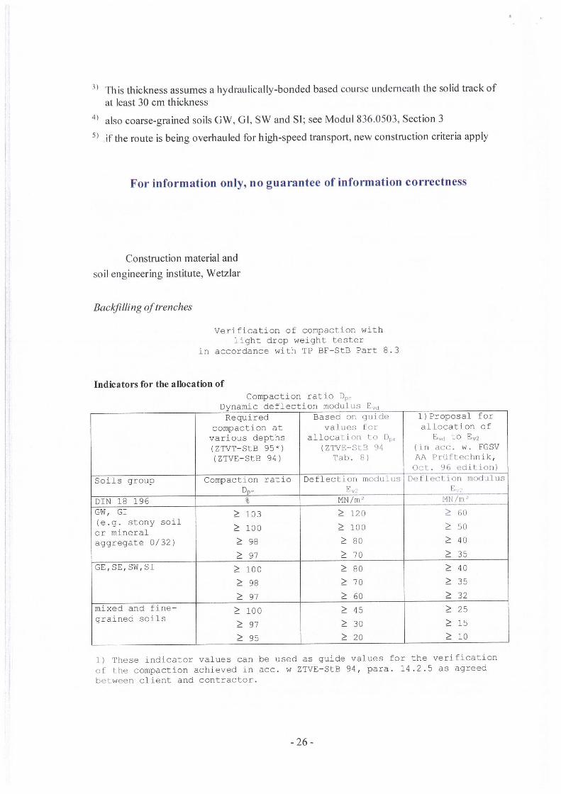
For information only, no guarantee of information correctness
Construction material andsoil engineering institute, Wetzlar
Backfiuing oftrenches
Verification of compaction withlight drop weight tester
in accordance with TP BF—StB Part 8.3
Indicators for the allocation ofCompaction ratio D,,,
Dynamic deflection modulus C,~Required Based on quide l)Proposal for
compaction at values fo, alLocation ofvarious depths allocation to ),~, E~, to E~2(ZTVT—StB 95*) (ZTVE-StB 04 (in drr. w. FGSV(ZTVE—StB 94) Tab. R) AA Priifl ‘hnik,
Oct. 96 ~.diti.on)
Soils group Compaction ratio Deflection modulus DeFI ccl i on modulus~ E
DIN 18 196 MN/m~ MN/n’GW, GI ≥ 103 ≥ 120 ≥ N)(e.g. stony soilor mineral ≥ 100 ≥ 100 ≥ 50aggregate 0/32) ≥ 98 ≥ 80 ≥ 40
≥ 97 ≥ 70 ≥ 35GE,SE,SW,SI ≥ 100 ≥ 80 ≥ 40
≥ 98 ≥ 70 ≥ 35
≥ 97 ≥ 60 ≥ 32mixed and fine— ≥ 100 ≥ 45 ≥ 25grained soils
≥ 97 ≥ 30 ≥ 15
≥95 ≥20 ≥10
1) These indicator values can be used as guide values for the verificationor Ehe compaction achieved in acc. w ZTVE—StB 94, para. 14.2.5 as agreedbetween client and contractor.

16. W/arrantv
We provide 2 months guarantee from date of acceptance by the final customer for all faultsoccurring on our equipment in the manner that we choose either to remedy any faultsoccurring free of charge or supply faulty parts new.No warranty claims can be made especially for damage caused by improper use, normal wear,handling which does not comply with the operating instructions, improper handling, excessiveloading, insufficient care and maintenance, non-use of original parts, use of incorrectaccessories, natural catastrophes or transport.
-27 -
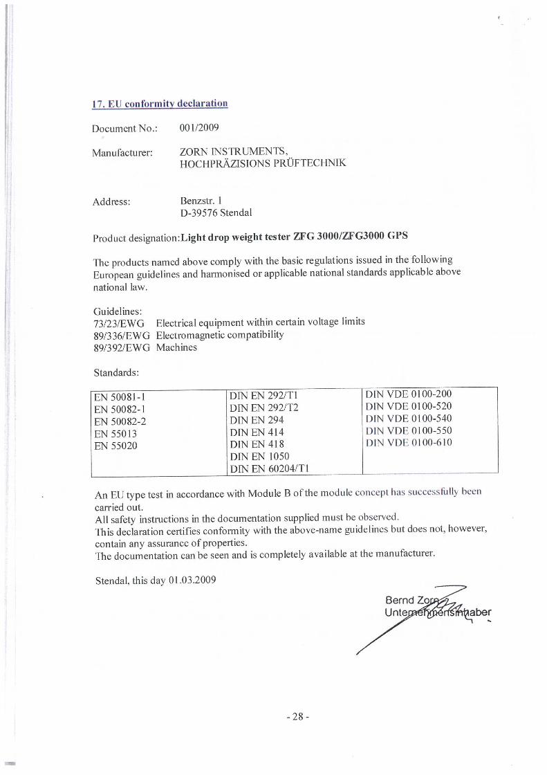
17. EU conformity declaration
Document No.: 001/2009
Manufacturer: ZORN INSTRUMENTS,HOCHPRAZISIONS PROFTECHNIK
Address: Benzstr. ID-39576 Stendal
Product designation:Light drop weight tester ZFG 3000/ZFG3000 GPS
The products named above comply with the basic regulations issued in the followingEuropean guidelines and harmonised or applicable national standards applicable abovenational law.
Guidelines:73/23IEWG89/336/EWG89/392/EWG
Standards:
Electrical equipment within certain voltage limitsElectromagnetic compatibilityMachines
EN 50081-1 DIN EN 292/TI DIN VDE 0100-200EN 50082-I DIN EN 292/fl DIN VDE 0100-520EN 50082-2 DEN EN 294 I)INVDEOIOO-540EN55013 DINEN4I4 I)INVDEOIOO-550EN55020 D[NEN4I8 l)INVDEOIOO-610
DEN EN 1050DEN EN 60204/TI
with Module B of the module concept has successliilly beenAn EU type test in accordancecarried out.All safety instructions in the documentation supplied must be observed.This declaration certifies conformity with the above-name guidelines but does not, however,contain any assurance of properties.The documentation can be seen and is completely available at the manufacturer.
Stendal, this day 01 03.2009
Bernd‘aber

to ~0

INSTRUMENTS
Benzstral3e 1, D —39576 StendalTelephone +49(0)3931 / 25273 — 0, fax +49(0)3931 /25273—10
~~‘w~v.zorn—instruireiits.de, inlb~l~zorn—instrurnents.de