Embed Size (px)
Citation preview

Operating Instructions
BioProTT™
Flow Measurement System

BioProTT™ Flow Measurement System Version 2.0 page 2 of 94
Brief Operating Instructions - Quick Guide BioProTT™ Flow Measurement System
Safety instructions Chapter 2.1 – Page 6
Familiarize yourself with the safety instructions!
Setting up and connecting the flow meter Chapter 6 - Page 18
Connect the BioProTT™ flow meter to power supply, e.g.
with supplied 24V DC power supply and connect analog or
digital interfaces as needed.
Installing flow sensor Chapter 8.1 - Page 43
Connect Clamp-On Transducer to BioProTT™ flow meter
by plugging it into the correct socket.
Please ensure that transducer is proper size for the tubing.
Insert tubing into BioProTT™ Clamp-On Transducer and
close lid. The flow direction is indicated with an arrow.
Prepare Measurement Chapter 8.2 - Page 43
Power the BioProTT™ flow meter on and wait some
seconds for initialization.
Usually a sensor will show a flow value even with no flow
present. Zero this (flow value) offset by pressing the
appropriate button, selecting the appropriate menu option,
sending a digital command or using remote zero.
Note: ensure that
correct calibration table is selected (for sensors with
more than one table programmed)
tubing is filled with medium,
there is sufficient coupling and
the liquid in the tubing is not moving (no flow) before
adjusting the zero offset (flow value ml/min!)
Perform custom calibration if necessary
Perform Measurement Chapter 8.7 - Page 47
The BioProTT™ flow measurement system is now ready
for use.
Please note: If troubleshooting is necessary please see chapter TROUBLESHOOTING.

BioProTT™ Flow Measurement System Version 2.0 page 3 of 94
TABLE OF CONTENTS
1 INTENDED USE AND RESTRICTIONS ........................................................................................... 6
1.1 INTENDED USE ..................................................................................................................................... 6 1.2 USAGE RESTRICTIONS AND LIMITATIONS ............................................................................................ 6
2 GENERAL SAFETY AND IMPORTANT INFORMATION ........................................................... 6
2.1 GENERAL SAFETY INFORMATION ......................................................................................................... 6 2.2 GENERAL IMPORTANT INFORMATION .................................................................................................. 9
3 SYMBOLS, UNITS AND ABBREVIATIONS .................................................................................. 10
3.1 SYMBOLS USED IN THESE OPERATING INSTRUCTIONS ........................................................................ 10 3.2 SYMBOLS ON EXTERNAL POWER SUPPLY UNIT ................................................................................. 10 3.3 SYMBOLS ON FLOW METER, SENSORS AND ON PACKAGING .............................................................. 11 3.4 UNITS ................................................................................................................................................. 13 3.5 DEFINITIONS AND ABBREVIATIONS .................................................................................................... 13
4 DESCRIPTION OF MEASURING PRINCIPLE ............................................................................. 14
5 PACKAGING CONTENTS ................................................................................................................ 15
6 INITIAL SET UP ................................................................................................................................. 18
6.1 IMPORTANT CURRENT LOOP DEFINITIONS ......................................................................................... 18 6.2 POWERING OF BIOPROTT™ FLOW METER ........................................................................................ 20 6.3 POWERING OVER ANALOG SOCKETS ................................................................................................. 21 6.4 CURRENT LOOP(S) POWERED BY FLOW METER ................................................................................. 22 6.5 CURRENT LOOP(S) POWERED BY EXTERNAL SUPPLY, E.G. FROM PCS ............................................... 23
7 INSTALLATION AND OPERATION OF BIOPROTT™ FLOWTRACK ................................... 26
7.1 FRONT PANEL BIOPROTT™ FLOWTRACK ......................................................................................... 26 7.2 REAR PANEL BIOPROTT™ FLOWTRACK ........................................................................................... 27
7.2.1 Pin Assignment and Cable Colors for Round Connector for Digital Interface ....................... 28 7.2.2 Pin Assignment and Cable Colors for Round Connectors for Power, Flow and RSS Interfaces
28 7.2.3 Connecting and Powering up .................................................................................................. 29
7.3 INSTALLATION AND OPERATION OF BIOPROTT™ FLOWTRACK DINRAIL ......................................... 30 7.3.1 DIN Rail Mounting .................................................................................................................. 31 7.3.2 Installation of Flow Sensor Extension Cable (IP50 at panel) ................................................. 31 7.3.3 Front and Rear Panel BioProTT™ FlowTrack DINrail ......................................................... 32 7.3.4 Remote Zero ............................................................................................................................. 33
7.3.4.1 Electrical Connection using BioProTT Power Supply........................................................................ 34 7.3.4.2 Electrical Connection using External Power Supply .......................................................................... 34 7.3.4.3 Remote Zero Pulse Response ............................................................................................................. 35
7.4 INSTALLATION AND OPERATION OF BIOPROTT™ FLOWTRACK PLUS ............................................... 36 7.4.1 Front Panel BioProTT™ FlowTrack plus ............................................................................... 37 7.4.2 Menu Structure of BioProTT™ FlowTrack plus ..................................................................... 38 7.4.3 Rear Panel BioProTT™ FlowTrack plus ................................................................................ 39 7.4.4 Connecting and Powering up .................................................................................................. 39
7.5 MOUNTING OF BIOPROTT™ FLOWTRACK PLUS FOR PANEL MOUNT ................................................ 40 7.5.1 Installation of Flow Meter ....................................................................................................... 40 7.5.2 Installation of Flow Sensor Extension Cable (IP 68 at panel) ................................................ 41 7.5.3 De-Installation of Flow Meter and Extension Cable ............................................................... 42
8 PERFORMING MEASUREMENTS ON TUBING SYSTEMS USING BIOPROTT™ CLAMP-
ON TRANSDUCERS .................................................................................................................................... 43
8.1 INSTALLATION OF THE BIOPROTT™ CLAMP-ON TRANSDUCER ........................................................ 43 8.2 CLAMPING FLOW SENSOR ONTO TUBE ............................................................................................... 43 8.3 MEASUREMENT ACCURACY AND TUBE ARRANGEMENT .................................................................... 44 8.4 RECEIVED SIGNAL STRENGTH (RSS / ACOUSTIC COUPLING)............................................................. 46 8.5 USE OF ACOUSTIC COUPLANT ............................................................................................................ 46 8.6 ZERO ADJUSTMENT............................................................................................................................ 47 8.7 PERFORMING FLOW MEASUREMENTS ................................................................................................ 47

BioProTT™ Flow Measurement System Version 2.0 page 4 of 94
8.7.1 Measurement Using the Analog Interface of BioProTT™ Flow Meters ................................. 47 8.7.1.1 Received Signal Strength (RSS / Acoustic Coupling) on Analog Interface........................................ 47 8.7.1.2 Flow Value on Analog Interface......................................................................................................... 48
8.7.2 Measurement Using the Digital Interface (RS232).................................................................. 52 8.7.3 Measurements Using BioProTT™ FlowTrack plus ................................................................. 56
8.7.3.1 Flow Value and Coupling ................................................................................................................... 56 8.7.3.2 Selection of Calibration Table ............................................................................................................ 57 8.7.3.3 Selection of Calibration Factor ........................................................................................................... 58 8.7.3.4 Adjustment of Brightness ................................................................................................................... 59 8.7.3.5 Totalizing ........................................................................................................................................... 59 8.7.3.6 Status and Error Information .............................................................................................................. 61
8.7.4 Custom Calibration Procedure ................................................................................................ 61
9 STATUS INFORMATION, TROUBLESHOOTING, SUPPORT AND SERVICE...................... 63
9.1 AVAILABLE STATUS CODES/INFORMATION FOR FLOW METER .......................................................... 63 9.2 AVAILABLE ERROR CODES/INFORMATION FOR FLOW METER ........................................................... 64 9.3 TROUBLESHOOTING ........................................................................................................................... 66 9.4 CHECKING CURRENT LOOPS OF FLOW METER ................................................................................... 69
9.4.1 Method 1 – Using Power from Flow Meter and Measuring with Ampere meter ..................... 69 9.4.2 Method 2 – Providing Power Externally in Current Loop and Measuring with Ampere Meter
70 9.4.3 Method 3 – Checking Functionality with Voltmeter ................................................................ 71
9.5 RECOMMENDED PERIODIC CHECKS ................................................................................................... 72 9.6 SUPPORT AND SERVICE ...................................................................................................................... 73
9.6.1 Contact Information for Technical Support ............................................................................. 73 9.6.2 Returns / RMA ......................................................................................................................... 74
10 CLEANING, LOW LEVEL DISINFECTION AND MAINTENANCE ......................................... 75
10.1 CLEANING OF THE BIOPROTT FLOW METER ............................................................................. 75 10.2 CLEANING AND DISINFECTION OF THE CLAMP-ON TRANSDUCER ................................................. 76
11 APPROVAL INFORMATION ........................................................................................................... 77
11.1 EU CE COMPLIANCE ..................................................................................................................... 77 11.2 US FCC COMPLIANCE .................................................................................................................. 77 11.3 CANADA COMPLIANCE .................................................................................................................. 77 11.4 ELECTRICAL SAFETY AND ELECTROMAGNETIC COMPATIBILITY ................................................... 78
12 TECHNICAL DESCRIPTION ........................................................................................................... 79
12.1 TECHNICAL DATA BIOPROTT™ FLOW METER ............................................................................ 79 12.2 TECHNICAL DATA BIOPROTT™ CLAMP-ON TRANSDUCER .......................................................... 81
13 ENVIRONMENTAL PROTECTION AND DISPOSAL ................................................................. 84
14 MANUFACTURER'S DECLARATIONS......................................................................................... 85
14.1 INFORMATION ON ACOUSTIC OUTPUT DATA................................................................................. 85 14.2 EU DECLARATION OF CONFORMITY ............................................................................................. 87 14.3 FCC CERTIFICATE OF COMPLIANCE .............................................................................................. 88
15 ORDERING INFORMATION FOR THE BIOPROTT™ FLOW MEASUREMENT SYSTEM
AND ACCESSORIES ................................................................................................................................... 89
16 RETURN INFORMATION AND DECLARATION OF CONTAMINATION ............................. 91
17 APPENDIX ........................................................................................................................................... 92
17.1 CALIBRATION INFORMATION FOR BIOPROTT™ CLAMP-ON TRANSDUCERS ................................ 92 17.2 CHANGES DUE TO SOFTWARE VERSION V3.0 ................................................................................ 92 17.3 OUTPUT STRINGS OF V2.4 VERSUS V3.0 ....................................................................................... 93

BioProTT™ Flow Measurement System Version 2.0 page 5 of 94
Read these Operating Instructions carefully before starting up the
device!
Although the BioProTT™ flow measurement system represents state-of-the-art
technology, the user may be put at risk if the device is operated incorrectly. You should
therefore carefully read the Operating Instructions before use. Inspect your equipment for
completeness and damage after first unpacking.
These instructions contain important information on the safe handling of the BioProTT™
flow measurement system and accessories. Read these Operating Instructions carefully
before using the device and accessories, and keep them in an easily accessible location.
Familiarize yourself with and observe all warning and safety information.
It is the responsibility of the operator of the device to ensure it is used, inspected and
maintained in accordance with the Operating Instructions. Subsequent revisions or
instructions from the manufacturer must also be taken into account in this regard.
The manufacturer reserves the right to modify technical data without prior notice. Your
local distributor will supply you with current information and updates to these Operating
Instructions.
Please note:
When BioProTT™ is used in this manual, it usually refers to the complete flow
measurement system consisting of flow meter and Clamp-On Transducer.
There are 3 versions of the flow meter:
o BioProTT™ FlowTrack: flow meter without display in standard industry
housing.
o BioProTT™ FlowTrack DINrail: flow meter without display for DIN rail
mounting in cabinets.
o BioProTT™ FlowTrack plus: flow meter with display and enhanced
functionality in standard industry housing as bench top or panel mount
device
The differences of the flow meters (including SW features) will be pointed out in
the appropriate chapters.
This manual covers the following software version(s) of the BioProTT™ flow meter:
o SW version SW 3.0.x.x
The software version can be retrieved using the display or the digital
interface.
o Further information and technical papers can be found on em-tec’s website.
The serial communication (output format) has been changed in V3.0
to support higher flow rates. This needs to be taken into account
when integrating with other software or process control.

BioProTT™ Flow Measurement System Version 2.0 page 6 of 94
1 Intended Use and Restrictions
If this device is not used as intended, the user may be exposed to
risks that were not taken into account during development.
1.1 Intended Use
The BioProTT™ flow measurement system is designed for non-invasive measurement
of volumetric flow of liquids. The measurement is based on the ultrasonic transit time
method. It is usually used in laboratory, bioprocess and industrial processes.
1.2 Usage Restrictions and Limitations
The BioProTT™ flow measurement system is not intended to be used
- In an outdoor environment
- With explosive liquids
- For gases
- As a legal metrological control
2 General Safety and Important Information
2.1 General Safety Information
Warning! The general safety information below must be observed
without fail to ensure safe handling of the device.
Type of danger Safety information
Risk of explosion,
Risk of fire
The BioProTT™ flow measurement system and accessories are not
intended for use in an explosive atmosphere, with explosive agents,
oxidants or flammable agents or gases.
Risk of failure to
safeguard a safety
operation of plant
or equipment
The BioProTT™ flow measurement system and accessories are not
intended for use to control and regulate a safety operation of a plant
or equipment, especially those requiring mandatory surveillance by
law.

BioProTT™ Flow Measurement System Version 2.0 page 7 of 94
Type of danger Safety information
Risk to safety due
to defective
device, applied
parts or
accessories
A defective device, sensors/parts or accessories must not be used
and must be replaced immediately. This applies in particular if the
cable insulation is damaged or if parts have broken off or are bent.
Electric shock Fit mains input plug of power supply before use.
The power supply unit may not be immersed into liquids and is
intended for use in dry locations. However, in the event of the
ingress of liquid, pull out the power plug immediately. Stop using
the device and return it to the factory for inspection; see chapter
RETURNS / RMA.
Risk to electrical
safety, fire or of
increased
electromagnetic
emissions or
lower resistance
of device to
interference
Use of accessories, power supply units, cables (lines) and sensors
other than those specified in these Operating Instructions is not
permitted.
Any external power supply that is not supplied with the system shall
have an output voltage of 24 V DC (±10 %), must not deliver more
as 6.25 A, shall be continuously short circuit protected and provide a
separate switch.
The device must not be used in residential areas.
If longer cable lengths are used than specified in these Operating
Instructions or more than one extension cable in series is used, the
emission of the device could increase or its immunity to interference could
be reduced. Existing cable ferrites must not be removed.
Please ensure that all national requirements with respect to EMC
and electrical safety regulations are met when connecting a power
supply that was NOT originally shipped.
See chapter ELECTRICAL SAFETY AND ELECTROMAGNETIC
COMPATIBILITY; see chapter INITIAL SET UP
Malfunctions,
inaccurate
measured value
due to high-
frequency devices
The BioProTT™ flow measurement system may be influenced by
radio frequency (RF) devices. This includes mobile RF
communication equipment. Use of a RF device in the vicinity of the
BioProTT™ flow measurement system may also cause its
accessories to malfunction which may, among other things, lead to
measured values being provided inaccurately or incorrectly.
Overheating of
the device &
power supply
Prevent the device and power supply from being covered and direct
heat or sun radiation.
Faulty repairs,
Malfunctions
The device must not be opened. Repairs to the device shall only be
carried out by authorized service personnel. Unauthorized opening
or repairs will void manufacturer’s warranty.
Faulty electrical
installation
Comply with the installation requirements; refer to the chapter
ELECTRICAL SAFETY AND ELECTROMAGNETIC
COMPATIBILITY.

BioProTT™ Flow Measurement System Version 2.0 page 8 of 94
Type of danger Safety information
Measuring
inaccuracy,
Risk to electrical
safety
The measuring accuracy and safety-relevant aspects should be
checked at least every 2 years. Please refer to chapter
RECOMMENDED PERIODIC CHECKSFehler! Verweisquelle
konnte nicht gefunden werden. for details.
Risk of
infection/environ-
mental
contamination
due to improper
disposal
The device and accessories must be disposed of in accordance with
the national specifications for waste electrical and electronic
devices.
In case microbial contamination may be present on the device after
being used, we recommend you dispose of these separately in
accordance with the applicable regulations.
In case microbial contaminated, device or accessories shall be
cleaned and disinfected before they are sent to the manufacturer.
Do not return a device/sensor if you are not absolutely certain that
all traces of hazardous substances have been removed, e.g.
substances which have penetrated crevices or diffused through
plastic. Refer to chapter RETURN INFORMATION AND
DECLARATION OF CONTAMINATION for additional
information.
Damage to the
flow
measurement
system by
chemicals
BioProTT™ components may be damaged or deteriorated when
coming in contact with aggressive chemical components as used in
liquid systems, couplants or cleaning solutions.
Therefore contact with chemicals should generally be avoided.
Ensure also that tubing used is compatible with intended fluid.
Please refer to chapter CLEANING, LOW LEVEL
DISINFECTION AND MAINTENANCE for details Table 1: General Safety Information
For more application-specific warnings, refer to the corresponding chapters.
The manufacturer only considers itself to be responsible for the safety, reliability and
usability of the device if:
The device is used in accordance with the instructions for use.
Installation, connection to the electricity supply and process control system,
additions, readjustments, changes or repairs and maintenance are only carried out
by qualified persons who have been authorized and trained. These qualified persons
must have read and understood this manual and must follow them accordingly.
The flow measurement system must be operated by persons authorized and trained
by the plant operator. Compliance with the instructions in this manual is
compulsory.
The manufacturer provides no warranty and assumes no liability in the event of non-
compliance with the above.

BioProTT™ Flow Measurement System Version 2.0 page 9 of 94
2.2 General Important Information
The following symbols are used in these Operating Instructions to highlight specific
information.
Caution! Important information regarding correct handling. To be
carried out and strictly observed!
If this following information is not observed, faults or damage to the
product or its surroundings may occur.
Type of damage Important information
Malfunction or
irreparable
damage
The BioProTT™ flow measurement system is intended to be used
with its own power supply (shipped with the system) or e.g. within
electrical control cabinets with their own power supply.
The DC power supply line shall be shorter than 30 m and shall not
leave the building.
Damage due to
ultrasonic sound
At all device settings of the BioProTT™ flow measurement system
the Clamp-On Transducer generates ultrasonic sound only at a very
low acoustic output level.
The ultrasonic sounds generated are harmless to persons, protein
solutions (e.g. blood, blood cells) and the environment according to
current knowledge, providing the system is used properly.
For more detailed information, see chapter INFORMATION ON
ACOUSTIC OUTPUT DATA.
Damage or mal
function
Unused connector sockets should be covered e.g. with the provided
flexible grip caps to avoid accumulation of dirt or fluids potentially
causing short circuits, corrosion or mal function.
No legal
metrological
control
Device is not designed to be used as a legal metrological control as
i.e. defined in EU Directive 2004/22/EC Measuring Instruments
Table 2: General important information

BioProTT™ Flow Measurement System Version 2.0 page 10 of 94
3 Symbols, Units and Abbreviations
All symbols and abbreviations used are explained in this chapter.
3.1 Symbols used in these Operating Instructions
The following symbols are used in these Operating Instructions to highlight specific
information.
Symbol Meaning
Warning!
This safety symbol precedes critical information that must be strictly
observed in order to prevent injuries and fatal hazards. This warning
symbol is the most important safety symbol.
Caution!
Important information regarding correct handling. Must be performed
and strictly observed!
If this information is not observed, faults or damage to the product or
its surroundings may occur. Table 3: Symbols Operating Instructions
3.2 Symbols on External Power Supply Unit
Symbol Meaning
Alternating current:
Alternating current must be fed to the supplied external power
supply unit. The values for the supply voltage must correspond to
those of the power supply unit: 100-240 VAC / 50-60 Hz.
Friwo Gerätebau GmbH (manufacturer logo)
Protection Class II (protective insulation)
As a safety guarantee, this power supply unit has additional
insulation to prevent dangerous touch voltage in the event of a fault.
IP40 Protected against access by wire
Ta40/B Rated ambient temperature/transformer class
Do not dispose of this device as domestic waste!
Devices must be disposed of as waste devices according to WEEE
directive and national legislation.
CE marking: The external power supply unit satisfies the
requirements of Low Voltage Directive 2006/92/EC and
EMC Directive 2004/108/EC.
UL test mark for recognized components for Canada and the USA
by Underwriter Laboratories Inc.

BioProTT™ Flow Measurement System Version 2.0 page 11 of 94
Symbol Meaning
European Norms Electrical Certification (10 = ID number of VDE)
Direct current
(24 V DC from external power supply unit)
Caution
Risk of electric shock. Dry location use only. Fit mains plug before
use AC/DC adapter.
Further warnings and precautions exist.
(Refer to these instructions for use)
Table 4: Symbols Power Supply
3.3 Symbols on Flow Meter, Sensors and on Packaging
Symbol Meaning
Caution
Further warnings and precautions exist.
(Refer to these instructions for use)
IP65 Protected against dust and high pressure water jets / wash down
from all directions (BioProTT™ FlowTrack, BioProTT
FlowTrack plus, BioProTT™ Clamp-On Transducer).
IP20 Protected against access by finger (BioProTT™ FlowTrack DINrail)
Direct current
(24 V DC from external power supply unit)
Do not dispose of this device as domestic waste!
Waste devices must be disposed of in accordance with WEEE
Directive and national legislation.
Manufacturer:
em-tec GmbH
Lerchenberg 20
86923 Finning
Germany
Year of Manufacturing
Serial number
Order number

BioProTT™ Flow Measurement System Version 2.0 page 12 of 94
Symbol Meaning
CE marking: This device complies with the relevant European
directives. The applicable legislation is given in the EU
DECLARATION OF CONFORMITY.
FCC-Mark: The device satisfies the requirements of the United States
Federal Communication Commission. See US FCC Compliance
Caution, fragile!
Handle with care!
Protect against moisture! Store in a dry place.
Temperature limit during storage
non-condensing
Moisture limit during storage (non-condensing)
Air pressure limit
Storage
Transport
Table 5: Symbols Devices and Packaging

BioProTT™ Flow Measurement System Version 2.0 page 13 of 94
3.4 Units
Unit Meaning
" Tube size in inches, 1 inch ≈ 25.4 mm
ID" x WT"
Tube dimensions in inches :
Outer diameter = internal diameter ID + (2 x wall thickness WT)
Table 6: Units
3.5 Definitions and Abbreviations
Definitions,
Abbreviation
Meaning
AWG American Wire Gauge
BCT BioProTT Clamp-On Transducer
CT Clamp-On Transducer
DAQ Data Acquisition System
EMC Electromagnetic Compatibility
flow meter BioProTT™ FlowTrack, BioProTT FlowTrack plus,
BioProTT FlowTrack DINrail
flow sensor BioProTT Clamp-On Transducer
N/A Not applicable
PCS Process Control System incl. DAQ
ID Inner diameter
OD Outer diameter
Qmax Maximum flow
TT Transit-Time
TTFM Ultrasonic Transit-Time Flow Measurement
RSS Received Signal Strength which corresponds to the acoustic coupling
WT Wall thickness
Table 7: Definitions and Abbreviations

BioProTT™ Flow Measurement System Version 2.0 page 14 of 94
4 Description of Measuring Principle
The physical measurement principles applied in the BioProTT™ flow measurement system
are described in this chapter.
The BioProTT™ flow measurement system uses the ultrasonic transit-time method (TT =
transit-time) which delivers precise flow values in tube systems and pipes.
The ultrasonic converters (piezoceramics) in the flow sensors transmit high-frequency
acoustic signals in and against the flow direction. The time difference between these
signals is proportional to the volumetric flow.
The basic principle is explained below.
Transmitter/
Receiver
Receiver/
Transmitter A
B
Tube
Flow
a
Figure 1: Principle of ultrasonic flow measurement (simplified using only two ceramics)
One piezoceramic (A) is excited by a set of high-frequency vibrations and transmits
ultrasonic waves to a second opposing piezoceramic (B) that acts as a receiver. The
piezoceramics are arranged at a specific angle α in relation to the flowing medium. The
transit time is influenced by the medium. The flow velocity of the medium can be
calculated using the measured transit time differences. The flow in liters per minute is
established using the known cross-section of the tube being scanned by ultrasonic
transmission.
Four ultrasound converters in a crosswise arrangement transmit high-frequency sound
signals alternately in and against the direction of the flow. The transit time for each
impulse is measured; the transit-time difference between the upstream and downstream
movement of the impulses is proportional to the volumetric flow.

BioProTT™ Flow Measurement System Version 2.0 page 15 of 94
5 Packaging Contents
The BioProTT™ flow measurement system is shipped with the following components:
One Flow meter in either of the following variants:
a) BioProTT™ FlowTrack (without display)
b) BioProTT™ FlowTrack plus (with display) as bench top model
c) BioProTT™ FlowTrack plus (with display) for panel mount
d) BioProTT™ FlowTrack DINrail (without display for DIN rail mounting)
Please note: Flexible grip caps are provided for all circular sockets and should
not be removed until a socket is actually used to avoid any dirt accumulation or
any potential short circuits.
One Power supply with country specific adaptor. Currently the following adaptors are
available: EURO, UK, USA/JAPAN, IEC - others on request.
Two pre-configured 2 m long cables with plug on one end and cage clamp terminal
blocks on other end. Included with flow meter variant a), b) and c).
One pre-configured serial cable, 2 m long, for digital serial output with plug on one
end and standard female D-sub connector. Included with flow meter variant a), b) and
c).

BioProTT™ Flow Measurement System Version 2.0 page 16 of 94
One male D-Sub serial to USB adapter for connection to standard USB ports.
Please download current driver from link specified on actual adapter labeling.
The current link is also available on em-tec’s web site.
One pre-configured serial cable, 2 m long, for digital output with ten (10) pole
terminal block on one end and standard female D-sub connector. Included with
BioProTT™ FlowTrack DINrail.
One pre-configured sensor line extension cable (ID12466), 1 m long for flow sensor
for use in process control cabinet. Included with flow meter BioProTT™ FlowTrack
DINrail.
BioProTT™ Flow Measurement System Version 2.0 page 17 of 94
One pre-configured sensor line extension cable (ID12560), 1.1 m long for flow
sensor for use in process control cabinet. Included with flow meter BioProTT™
FlowTrack plus (with display) for panel mount. A watertight protection cap is
included.
One BioProTT™ Clamp-On Transducer
The BioProTT™ Clamp-On Transducer is shipped pre calibrated and ready to be
connected to either of the flow meters. It is included in the shipment if it has been
ordered accordingly.
One Printed Operating Instructions

BioProTT™ Flow Measurement System Version 2.0 page 18 of 94
6 Initial Set Up
In this chapter some basic consideration about integration of the BioProTT flow meters are
given and appropriate schematics of power supply and wiring of current loops are shown.
6.1 Important Current Loop Definitions
Generally, devices in 4-20 mA environments can be classified based on the current source
of the 4-20 mA loop as “active” or “passive”. Passive devices or sensors rely on (external)
loop power, whereas active devices are powering the current loop.
With respect to the 2-/4-wire classification of sensors, as a rule of thumb, one can assume
that 2-wire sensors are usually working in passive mode, whereas 4-wire sensors can
usually support the signal current loop being passive or active.
The BioProTT™ flow measurement system supports passive and active modes of
operation for flow and RSS current loop – see figure below. However, the flow meter
always needs power to operate!
Figure 2: BioProTT™ flow meter supporting “passive” loop configuration (example: flow)
BioProTT™ Flow Measurement System Version 2.0 page 19 of 94
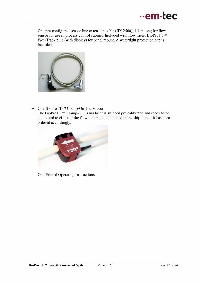
Figure 3: BioProTT™ flow meter supporting “active” loop configuration (example: flow)
The figures below show some of the electrical design of the BioProTT™ flow meters
which is important to properly wire the system. The pin assignment corresponds to the pins
as outlined in the following chapters.
Figure 4: BioProTT™ flow meter schematics with focus on power supply (w/o DIN rail variant)

BioProTT™ Flow Measurement System Version 2.0 page 20 of 94
Figure 5: BioProTT™ FlowTrack DINrail schematics with focus on power supply
6.2 Powering of BioProTT™ Flow Meter
The flow meter works with DC power, which can be supplied with
The power supply unit shipped with the system using the power socket or
With an external 24 V DC (±10%) power supply delivering at least 300 mA and
continuously short circuit protected.
o DC power can be supplied either through PIN 1/3 of the Power, Flow or
RSS socket on BioProTT™ FlowTrack and BioProTT™ FlowTrack plus.
o BioProTT™ FlowTrack DINrail can be supplied by DC power via PIN 1/2
of the terminal block or PIN 1/3 of the Power socket.

BioProTT™ Flow Measurement System Version 2.0 page 21 of 94
o This option is e.g. useful, when connecting it to a process control and
centrally powering the devices on or off. In case power is provided via the
Flow or RSS socket or the terminal block, the on/off button is no longer
“active”, i.e. the flow meter will start up as soon as power is available. In
case of a device error the power supply must be turned off.
When power is supplied via the power socket the on/off switch is used
to power on the flow meter otherwise the on/off switch does not have
an effect.
Ensure that there are no conflicting power sources/voltages applied to
Pin 1 and Pin 3 of either of the Power, Flow or RSS socket, as they are
internally bridged between the sockets.
For the BioProTT™ FlowTrack DINrail, please ensure this similarly
between Pin 1 and Pin3 of the Power socket and Pin 1 and 2 of the
terminal block.
6.3 Powering Over Analog Sockets
Below pin assignments and cable colors for flow meters with round connectors for Power,
Flow and RSS sockets are shown.
Figure 6: BioProTT flow meter rear view with one analog plug connected -example w/ Flow socket
Figure 7: BioProTT flow meter: view of power and analog Flow and RSS round sockets
Pin No Signal Power Signal Flow/RSS Wire color
(in supplied cabling)
1 24 V (24C_in) 24 V (24C_in) Brown
2 Not assigned Current Loop + White
3 Ground in (GND_in) Ground in (GND_in) Blue
4 Not assigned Current Loop - Black Table 8: Pin assignment BioProTT™ flow meter with round connectors

BioProTT™ Flow Measurement System Version 2.0 page 22 of 94
6.4 Current Loop(s) powered by Flow Meter
In this set-up, the flow meter current loop(s) are powered by the flow measurement system,
using wire bridges. From a flow meter perspective the current loop is “active”.
The wire bridge is applied from Pin 1 to Pin 2 of the Flow respective RSS cable or the
respective terminal block connections from BioProTT™ FlowTrack DINrail.
For details see the circuit diagrams below and observe the wiring instructions.
Figure 8: BioProTT flow meter rear view with one analog plug connected -example w/ flow socket
Pin No Flow / RSS Wire Color
(in supplied cabling)
Connection
1 24 V (24C_in) Brown + 24 V DC supply
2 Current Loop + White Connect Pin 1
with Pin 2
3 Ground in (GND_in) Blue Ground (GND) /
Return of PCS
4 Current Loop - Black Send (+) of PCS Table 9: Wiring connections for BioProTT™ flow meter with round connectors and flow meter power
Figure 9: Schematics – showing wiring of BioProTT™ FlowTrack /plus with Flow and RSS current
loop being connected and powered using the flow meter power supply

BioProTT™ Flow Measurement System Version 2.0 page 23 of 94
Figure 10: Schematics – showing the terminal block wiring of BioProTT™ FlowTrack DINrail with
Flow and RSS current loop being powered via flow meter and power supply shipped with unit
6.5 Current Loop(s) powered by External Supply, e.g. from PCS
In this set-up, the flow meter current loop does not have to be powered by the flow
measurement system, as it is already being supplied with an external power supply, e.g.
using either power from a signal processing card of a PCS or separate power supply.
From a flow meter perspective the current loop is “passive”.
For details see the circuit diagrams as follows and observe the wiring instructions.

BioProTT™ Flow Measurement System Version 2.0 page 24 of 94
Figure 11: BioProTT flow meter rear view with one analog plug connected -example w/ flow socket
Pin No Flow / RSS Wire color
(in supplied cabling)
Connection
1 24 V (24C_in) Brown Not connected
2 Current Loop + White Receive (-) of PCS
3 Ground in (GND_in) Blue Not connected
4 Current Loop - Black Send (+) of PCS Table 10: Wiring connections for BioProTT™ flow meter with round connectors and external power
Figure 12: Schematics – showing wiring of BioProTT™ FlowTrack /plus with Flow and RSS current
loop being powered via external power supply while the flow meter is powered with power supply
shipped with unit

BioProTT™ Flow Measurement System Version 2.0 page 25 of 94
Figure 13: Schematics – showing the terminal block wiring of BioProTT™ FlowTrack DINrail with
Flow and RSS current loop being powered via external power supply in PCS while flow meter is
powered with power supply shipped with unit
Figure 14: Schematics – showing the terminal block wiring of BioProTT™ FlowTrack DINrail with
flow and RSS current loop being powered via signal processing cards of PCS while flow meter is
powered with power supply shipped with unit

BioProTT™ Flow Measurement System Version 2.0 page 26 of 94
7 Installation and Operation of BioProTT™ FlowTrack
Compliance with the prescribed operating parameters and safety
information must be ensured prior to putting into service. The following
installation instructions must be strictly observed.
The BioProTT™ FlowTrack can be used as bench top flow meter or mounted with screws
on surfaces.
The BioProTT™ FlowTrack is connected to the mains supply via the corresponding power
supply unit, via the process control or another external power supply meeting the
requirements as outlined in chapter POWERING OF BIOPROTT™ Flow Meter.
The device is being powered on or off by
pushing the switch at the rear of the flow meter when powered through the dedicated
power input
OR alternatively by connecting/disconnecting a power supply via one of the analog
interfaces (Flow or RSS)
A green LED on the BioProTT™ FlowTrack indicates that it is has been powered-on and
initialized.
7.1 Front Panel BioProTT™ FlowTrack
Figure 15: Front view of BioProTT FlowTrack
Components Description
1 Push button
“Zero adjustment”
Push button to adjust offset at zero flow. The zero
adjustment is performed after button is released when
coupling is sufficient.
2 Status LED A green light indicates device has been powered-on. The
system requires a few seconds for powering on and
initialization. Table 11: Front panel BioProTT™ FlowTrack
1 2

BioProTT™ Flow Measurement System Version 2.0 page 27 of 94
7.2 Rear Panel BioProTT™ FlowTrack
Figure 16: Rear view of BioProTT FlowTrack
Components Description
1 On/Off button Push the button to power the device on or off.
Note: this button is only relevant when power is supplied
via the power socket. The button does not affect power
supplied via either Flow or RSS socket.
2 Power 4-pin connecting socket for DC power.
Note: only 2 pins are actually used.
3 Digital out 3-pin connecting socket for the signal digital interface.
4 Flow 4-pin connecting socket for the analog flow signal.
5 RSS 4-pin connecting socket for the analog signal “received
signal strength” (RSS).
6 Flow Sensor 16-pin connecting socket for the
BioProTT™ Clamp-On Transducer connector with push
and pull unlock mechanism. Table 12: Rear panel BioProTT™ FlowTrack.4
2 3 4 5 6 1
BioProTT™ Flow Measurement System Version 2.0 page 28 of 94
7.2.1 Pin Assignment and Cable Colors for Round Connector for Digital
Interface
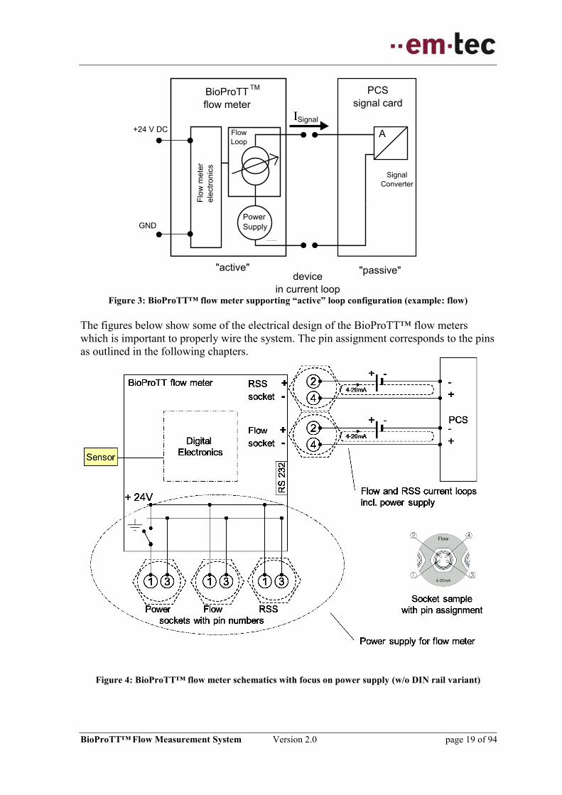
Please note: the supplied serial cable for the digital interface is completely wired and
ready to use.
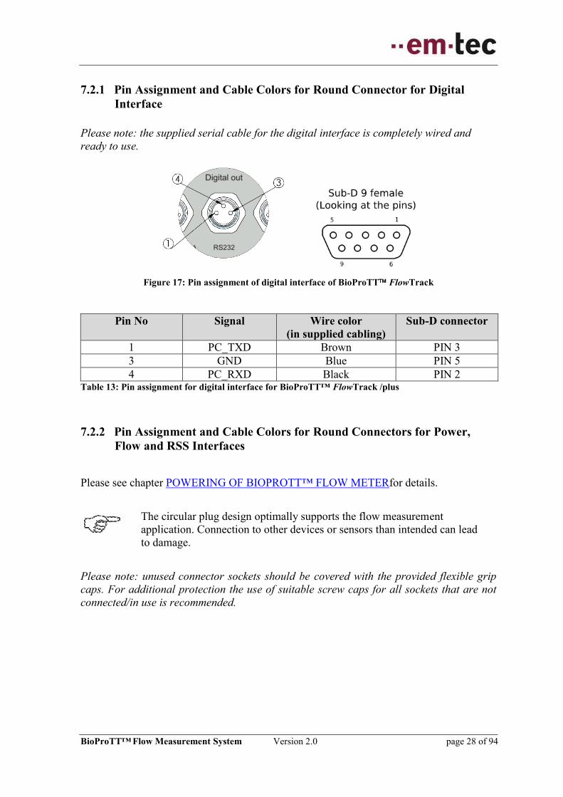
Figure 17: Pin assignment of digital interface of BioProTT FlowTrack
Pin No Signal Wire color
(in supplied cabling)
Sub-D connector
1 PC_TXD Brown PIN 3
3 GND Blue PIN 5
4 PC_RXD Black PIN 2 Table 13: Pin assignment for digital interface for BioProTT™ FlowTrack /plus
7.2.2 Pin Assignment and Cable Colors for Round Connectors for Power,
Flow and RSS Interfaces
Please see chapter POWERING OF BIOPROTT™ FLOW METERfor details.
The circular plug design optimally supports the flow measurement
application. Connection to other devices or sensors than intended can lead
to damage.
Please note: unused connector sockets should be covered with the provided flexible grip
caps. For additional protection the use of suitable screw caps for all sockets that are not
connected/in use is recommended.

BioProTT™ Flow Measurement System Version 2.0 page 29 of 94
7.2.3 Connecting and Powering up
The external power supply must not deliver more as 6.25 A at 24 VDC,
shall be continuously short circuit protected and have a separate switch.
Please ensure that all national requirements with respect to EMC and
electrical safety regulations are met for when connecting a power
supply that was NOT originally shipped.
The BioProTT™ flow meter shall be powered by 24 V DC (±10 %).
The power supply shall deliver at least 300 mA.
Please note: the flow meter can be powered with the provided power supply or with
another external power supply meeting the above mentioned specifications. If the power
supply does not meet the specifications above the protection provided by the device may be
impaired.
For installation with provided power supply observe the following steps:
1. Connect power supply
2. Connect Clamp-On Transducer to BioProTT™ flow meter.
3. Connect the 4-20 mA and/or digital serial output to your data acquisition system. The
connectors should be firmly tightened. Unused connector sockets should be covered
with provided flexible grip caps.
4. Power on the device with the switch. Wait some seconds until the system is
completely initialized. The system will automatically start to transfer measurement
values.
Please note: The current loops can either be powered through the process control
system or via the flow meter. The wiring needs to be done as show in chapter
INITIAL SET UP
5. Clamp transducer around tubing (for details see chapter INSTALLATION OF THE
BIOPROTT™ CLAMP-ON TRANSDUCER). An arrow on the sensor lid indicates
the flow direction; make sure that the sensor is oriented in the flow direction
otherwise negative readings occur. Make sure the tubing size, material and conditions
fit calibration data and the sensor lid is closed (locked in) to assure a reliable
measurement.
6. Select corresponding sensor table; the default setting is table 1
7. If not yet done fill tubing with liquid, you will see an increase of the RSS value.

BioProTT™ Flow Measurement System Version 2.0 page 30 of 94
8. Make sure that the liquid is not in motion and press the Zero Adjustment Button.
Pressing the zero offset button while the fluid is in motion will cause errors in the
flow measurement reading, due to wrong flow offset.
9. The flow measurement system is now ready for use.
Please note: when system is powered down, the sensor will reset to factory defaults.
7.3 Installation and Operation of BioProTT™ FlowTrack DINrail
Compliance with the prescribed operating parameters and safety
information must be ensured prior to putting into service. The following
installation instructions must be strictly observed.
The terminal block requires a screwdriver with 2.5 mm blade. The wires
used in conjunction with the terminal block should not exceed 1.5 mm2,
The BioProTT™ FlowTrack DINrail flow meter supports DIN rail mounting, e.g. for use
in cabinets of process controls. From a feature point of view, the device is identical with
the BioProTT™ FlowTrack. The physical connections have been moved and the form
factor has partially been changed to support specific installation environment.
The flow meter is connected to the mains via the process control or another external power
supply meeting the requirements as outlined in chapter POWERING OF BIOPROTT™
Flow Meter.
The device is powered either by
Power socket and pushing the “power on/off” switch at the front of the flow meter
when powered through the dedicated power input.
Please note: this switch is available, but usually not used, i.e. typically the switch is
always in the “on” position.
External power supply via terminal block
A green LED on the BioProTT™ FlowTrack DINrail indicates that it is has been powered-
on. The system requires some seconds for initializing.

BioProTT™ Flow Measurement System Version 2.0 page 31 of 94
7.3.1 DIN Rail Mounting
BioProTT™ FlowTrack DINrail is equipped with a mounting adapter for DIN rail type O,
35 mm x 7.5 mm or compatible. Position the upper hook at the rear on the DIN rail and
push in the lower. Please ensure that it is firmly mounted onto the rail before setting up any
connections.
When removing the device, push down the spring loaded bracket with a minus screwdriver
and pull.
Spring loaded DIN rail adapter
DIN rail type O, 35 mm x 7.5 mm
Figure 18: Flow meter mounting on DIN rail
7.3.2 Installation of Flow Sensor Extension Cable (IP50 at panel)
The female plug (Lemo Type PFG.2B.316.CLLD72) of the flow sensor extension cable
can be mounted in the cabinet wall with a thickness up to 6.5 mm (0.26 inch). The male
plug is inserted in the sensor port of the BioProTT™ FlowTrack DINrail. The cut out panel
is indicated below. The red marks indicate the correct orientation of the connection.
Figure 19: Panel cut out in cabinet
Please use the yellow cap to protect the plug from dust when not needed or use compatible
accessories from Lemo or ODU to cover the plug.
Please ensure that only one extension cable is used for connecting a flow sensor.

BioProTT™ Flow Measurement System Version 2.0 page 32 of 94
7.3.3 Front and Rear Panel BioProTT™ FlowTrack DINrail
Figure 20: Front and rear view of BioProTT FlowTrack DINrail
Components Description
1 Terminal block 10-pin connecting socket for terminal block with PIN
assignment as shown below.
2 Flow Sensor 16-pin connecting socket for the
BioProTT™ Clamp-On Transducer or extension cable.
3 On/Off button Push the button to power the device on or off.
Note: this button is only relevant when power is supplied
via the power socket. The button does not affect power
supplied via terminal block.
4 Status LED A green light indicates device has been powered-on. The
system requires some seconds for initializing.
5 Power 4-pin connecting socket for DC power.
Note: only 2 pins are actually used.
6 Push button
“Zero adjustment”
Push button to adjust offset at zero flow. The zero
adjustment is performed after button is released when
coupling is sufficient.
7 Mounting adapter Adapter plate for DIN rail mounting with spring loaded
lock mechanism. Table 14: Front and rear panel BioProTT™ FlowTrack DINrail
2 3 4 5 6 1 7

BioProTT™ Flow Measurement System Version 2.0 page 33 of 94
The PIN assignment on the terminal adapter block respectively the corresponding plug is
as follows:
PIN Number Meaning Color (in scheme) Remark
1 +24V Black
2 Ground Blue
3 Flow Current Loop + White
4 Flow Current Loop - Brown
5 RSS Current Loop + Yellow
6 RSS Current Loop - Green
7 PC_TXD Brown PIN 3 Sub-D
8 GND Blue PIN 5 Sub-D
9 PC_RXD Black PIN 2 Sub-D
10 Remote Zero + Red Pulse input Table 15: Terminal Block pin assignment for BioProTT™ FlowTrack DINrail
The terminal block connector for BioProTT™ FlowTrack DINrail is prewired and ready to
use for serial communication.
Figure 21: Pre-wired terminal block of BioProTT FlowTrack DINrail
7.3.4 Remote Zero
BioProTT™ FlowTrack DINRail devices with software version SW 3.0 or later have an
integrated “Remote Zero” option to correct the offset by remote control switch. Please see
chapter ZERO ADJUSTMENT for correct zeroing conditions.
The flow offset correction can be performed by pushing the “Zero adjustment” button on
the panel or additionally by generating a direct current voltage pulse by a switch on PIN
10. The digital input for remote zero accepts pulses of 24 V DC ± 10% and has an internal
current consumption of < 25 mA.

BioProTT™ Flow Measurement System Version 2.0 page 34 of 94
7.3.4.1 Electrical Connection using BioProTT Power Supply
Figure 22: Remote Zero using BioProTT Power Supply
When using the BioProTT™ power supply, a switch contact between PIN 1 and PIN 10
can be used to generate the remote zero pulse.
7.3.4.2 Electrical Connection using External Power Supply
Figure 23: Remote Zero using external Power Supply
When using an external power supply a switch contact between +24 V DC of the power
supply and PIN 10 can be used to generate the remote zero pulse. PIN 2 must be connected
to the GND of the power supply.
Please ensure the correct polarity of the electrical connection to avoid
device damage!

BioProTT™ Flow Measurement System Version 2.0 page 35 of 94
7.3.4.3 Remote Zero Pulse Response
Figure 24: Remote Zero Pulse induces Offset correction
Please see chapter ZERO ADJUSTMENT for correct zeroing conditions.
The zero adjustment is triggered on the falling edge of the 24 V DC remote zero pulse with
pulse length of least 500 ms and only accepted by system when coupling is sufficient. The
time interval between two pulses should not be below 2000 ms.

BioProTT™ Flow Measurement System Version 2.0 page 36 of 94
7.4 Installation and Operation of BioProTT™ FlowTrack plus
Compliance with the prescribed operating parameters and safety
information must be ensured prior to set up. The following installation
instructions must be strictly observed.
The BioProTT™ FlowTrack plus is available as bench top device. In addition, the
BioProTT™ FlowTrack plus can also be ordered in a variant for panel mount. The devices
are identical in features and differ only in their mounting options, which are covered in
section MOUNTING OF BIOPROTT™ FLOWTRACK PLUS FOR PANEL MOUNT.
The device is powered on or off by
pushing the switch at the rear of the flow meter when powered through the dedicated
power input
OR alternatively by connecting/disconnecting a DC power supply via one of the
analog interfaces (on/off switch is not active) or the power socket (which engages the
on/off switch)

BioProTT™ Flow Measurement System Version 2.0 page 37 of 94
7.4.1 Front Panel BioProTT™ FlowTrack plus
After power on, the flow meter takes some seconds for initialization.
The device is ready to operate, once the “flow” screen appears.
Please note: the display will be updated every second.
Figure 25: Front view of BioProTT FlowTrack plus
Basic operation of the device:
Button Meaning
The Up- and Down Arrow Buttons are used to select a possible
setting on the current screen or switch to the previous / next
screen.
If a selection of a value is possible, “sel” is displayed on the
screen.
The Enter Button is used
to change to “sel” mode,
to confirm a value or change and exit “sel” mode and
to change from “hold” to “run” status when in totalizer
mode.
Note: Press this button only short time, otherwise “sel” mode
may be left.
The Zero Adjustment Button is used for zero adjustment of the
flow or reset totalizer value(s) and exclamation mark.
Table 16: Front panel elements for BioProTT™ FlowTrack plus

BioProTT™ Flow Measurement System Version 2.0 page 38 of 94
7.4.2 Menu Structure of BioProTT™ FlowTrack plus
Flow chart of menu structure:
Figure 26: Menu structure of BioProTT FlowTrack plus
Zero Flow / Measure Flow
Initializing Device
Start/Stop/Reset Totalizing*
Set Calibration Table*
Set Calibration Factor*
Adjust Brightness
Display Status Information
Note: The message “initializing
device” only appears after
switching on the device.
*Screens can be accessed only if
a valid sensor is connected.
BioProTT™ Flow Measurement System Version 2.0 page 39 of 94
7.4.3 Rear Panel BioProTT™ FlowTrack plus
The rear panel of BioProTT™ FlowTrack plus is identical to the flow meter without
display, i.e. BioProTT™ FlowTrack. Please see chapter REAR PANEL BIOPROTT™
FLOWTRACK.
7.4.4 Connecting and Powering up
The flow meter is operated with the provided power supply.
Please note: the flow meter can alternatively be powered via an external power supply
either via the dedicated power input or either of the analog sockets. For details see chapter
POWERING OF BIOPROTT™ Flow Meter .
1. Connect power supply unit that is shipped with the device
2. Connect Clamp-On Transducer to the BioProTT™ flow meter.
3. Connect the 4-20 mA and/or digital serial output to your data acquisition system.
The connectors should be firmly tightened. Unused connector sockets should be
covered with provided flexible grip caps.
4. Power on the device with the switch. Wait some seconds for initialization, which is
done when the flow screen appears. The system will automatically start to transfer
measurement values.
Please note: The Current loops can either be powered through the process control
system or are powered by the flow meter. The wiring needs to be done as shown in
chapter INITIAL SET UP.
5. Clamp transducer around tubing (for details see chapter INSTALLATION OF THE
BIOPROTT™ CLAMP-ON TRANSDUCER). An arrow on the sensor lid indicates
the flow direction; make sure that sensor is oriented in the flow direction
otherwise negative readings occur. Negative Values will be shown correctly on the
display and in the digital reading. However, the analog interface will output
negative flow values into the range of 1 mA to 4 mA to the extent possible. For
details see chapter: MEASUREMENT USING THE ANALOG INTERFACE OF
BIOPROTT™ FLOW METERS. Make sure the tubing size and material fit and the
sensor lid is closed (locked in).
6. Select the appropriate sensor table
7. If not yet done fill tubing with liquid, you will see an increase of the RSS value on
the screen (or the other corresponding interfaces).
8. Make sure that the liquid is not in motion and press the Zero adjustment button on
BioProTT™ FlowTrack plus when in the flow screen.
9. The flow measurement system is now ready for use.

BioProTT™ Flow Measurement System Version 2.0 page 40 of 94
7.5 Mounting of BioProTT™ FlowTrack plus for Panel Mount
7.5.1 Installation of Flow Meter
The BioProTT™ FlowTrack plus for panel mount with standard industry housing is
designed as device which is mounted in a panel. When mounted it supports IP66 at the
panel.
The flow meter is equipped with larger face plate which can be mounted with 6 M3 (ISO
Metric Coarse Thread DIN 13) screw nuts on threaded bars. See below diagram for exact
location and dimensions of threaded bars as well as the panel cut out (in [inch] and [cm]).
Screws nuts must be tightened with torque value of 0.5 Nm +/-0.1 Nm to reach IP level
mentioned above when mounted in panel.
The intended maximum panel thickness supported is 3mm.
Figure 27: Front and rear view of BioProTT FlowTrack plus in panel

BioProTT™ Flow Measurement System Version 2.0 page 41 of 94
Figure 28: Drill template – values in [mm] and [inch]
7.5.2 Installation of Flow Sensor Extension Cable (IP 68 at panel)
The female socket (ODU Type G82B0C-P16LFG0-000L) of the flow sensor extension
cable can be mounted in the cabinet wall with a thickness up to 3 mm (0.12 inch). In order
to achieve the specified IP rating, the special ODU nutdriver for slotted mounting nut type
702 098 001 000 000 must be used. The maximum torque value is 4.5 Nm.
The male plug is inserted in the sensor port of the BioProTT™ FlowTrack plus. The panel
cut out panel is indicated below. The red marks indicate the correct orientation of the
connection.

BioProTT™ Flow Measurement System Version 2.0 page 42 of 94
Figure 29: Panel cut out in cabinet in [mm]
Please use the provided cap to protect the plug from dust etc. and achieve above IP rating
when no sensor is connected.
Please ensure that only one extension cable is used for connecting a flow sensor.
7.5.3 De-Installation of Flow Meter and Extension Cable
If the flow meter needs to be un-mounted from the panel, please disconnect all electrical
connections and open only the screw nuts accessible from inside the panel which fix the
faceplate of the device to the panel. Do not loosen any of the four cross-head screws on the
front of the device.
For de-installation of the sensor extension cable, please open screw nut of socket
accessible from front of panel.
When removing the device and cable e.g. for servicing please perform the mounting steps
in reverse order. In case of remounting the tightness of the once compressed gasket may be
compromised.

BioProTT™ Flow Measurement System Version 2.0 page 43 of 94
8 Performing Measurements on Tubing Systems using
BioProTT™ Clamp-On Transducers
8.1 Installation of the BioProTT™ Clamp-On Transducer
The Clamp-On transducer and the extension lines contain a push and pull locking
mechanism to avoid unintended disconnection. This permits the simple insertion and
locking. Unlocking of the connector is performed by pulling on the connector housing.
Make sure you are using the tubing, medium and temperature for which the
transducer was calibrated. The stated measurement accuracy cannot be
guaranteed if the measurements are carried out using tubing that differs in
size, wall thickness or material from the tubing on which the factory
calibration was performed. If measuring with at a different temperature or
with a different medium than the factory calibration, measurement errors
may occur unless adjustments are made by performing a custom calibration
on site and adjusting the calibration factor.
The calibration parameters are listed in the calibration report supplied with
the transducer.
Ensure that the sensor surface and tubing are clean for good coupling.
Select a location so that bubbles cannot accumulate, like below the highest
point of the overall tubing line.
8.2 Clamping Flow Sensor onto Tube
The 16-pin circular connector of the BioProTT™ Clamp-On Transducer is connected to
the BioProTT™ flow meter (see e.g. VIEW OF FRONT AND REAR). The transducer is
then clamped to the tube.
To obtain a positive flow value, make sure the arrow is pointing in the flow
direction.

BioProTT™ Flow Measurement System Version 2.0 page 44 of 94
Clamp the transducer onto the tube as follows:
Figure 30: Clamping onto tube
1. Open the spring lock and lift up the cover.
2. Insert the tube into the recess provided.
3. Close the lid by applying gentle pressure until the spring lock snaps into place.
4. Please note: the tubing should fit snugly in the transducer and should not be loose.
If the Clamp-On Transducer is used at significantly different parameters
compared to the calibration, like medium temperatures, this can lead to
inaccurate measurement results.
Please note: Customer-specific calibrations can also be carried out on request. Please
contact our SUPPORT AND SERVICE DEPARTMENT for further details.
8.3 Measurement Accuracy and Tube Arrangement
Accuracy ± 3% of reading ± max. 20 ml/min, for all
transducer sizes up to 1/2 x 1/8”
The accuracy has been confirmed under the following reference conditions:
Liquid temperature calibration temperature ±5°C (± 9° F)
Ambient temperature 20°C ±5°C (68° ± 9° F)
Straight inlet section 10 x ID of tubing, fully developed flow profile
Tubing Raumedic-ECC-Blood Line PVC
Acoustic couplant applied
Calibration factor 1.00

BioProTT™ Flow Measurement System Version 2.0 page 45 of 94
Figure 31: Accuracy graph
Optimized Accuracy:
As the measurement allows a maximal flexibility with respect to positioning the sensor the
given accuracy is a standard under the reference conditions. Certain setups allow higher
levels of accuracy and can be evaluated by a factory calibration certificate on customer
request.
Please also observe the steps below to ensure optimal measurement conditions.
Ensure a straight lead-in and run-on area (“straight inlet”):
To prevent turbulence and the associated measurement inaccuracies, it is
recommended to stretch the tube out straight in the area where it is clamped.
Notes on measurement accuracy:
Place the sensor on straight part of the tubing to avoid measurement in areas of
recirculation, vortices or spin (preferably at least 6 inches before and behind the
sensor.)
Figure 32: Using Clamp-On Transducer on straight part of tubing
Allow the sensor to reach a stable temperature profile before pressing the offset adjust
button; e.g. if the sensor has ambient temperature and the liquid medium a different
temperature, it usually takes a few minutes until a stable temperature profile is
reached.
Use only the specified tubing.
Keep to the specified temperature range of the liquid:
calibration temperature ±5°C (± 9° F).
Make sure that there is sufficient acoustic coupling (see next chapter).

BioProTT™ Flow Measurement System Version 2.0 page 46 of 94
8.4 Received Signal Strength (RSS / Acoustic Coupling)
The received signal strength (RSS) of the ultrasound beam is an indication of the ultrasonic
signal transmission quality through liquid, tube and sensor. In this context the RSS value is
an indication for acoustic coupling. A sufficient acoustic coupling is a pre-requisite for
accurate measurements. Please ensure that the right calibration table with the correct table
and medium is selected.
Sufficient acoustic coupling is reached when the indicated RSS value is greater than
50%. Below 50% the flow measurement result is considered to be inaccurate and is
no longer shown on the different interfaces.
Note: The RSS value is shown on the display or indicated on analog and digital
interfaces when a valid sensor is connected.
8.5 Use of Acoustic Couplant
In order to ensure good repeatability of the flow measurement, acoustic couplant should be
applied to the tube before use. This is especially important when soft tubing (like e.g.
silicone) with a low wall thickness is used. Fitting this tubing into the measurement
channel might lead to concave folding of the tubing wall and misalignment (low coupling,
acoustic focuses) to the active sensor areas. A couplant ensures an easy slip of the tube in
the channel and provides repeatable alignment of the tubing wall.
To ensure optimal measurement em-tec will provide support about the use of couplant for
your specific tubing- sensor system.
Note: It will be shown in the calibration table and, if requested, in the calibration certificate
if a sensor was calibrated with or without the specified couplant. Please make sure that
your measurements are performed accordingly. Otherwise over amplification or too low
coupling might occur.
If deterioration in the coupling is evident e.g. during long-term measurements, this is
normally a sign that the couplant is drying out. To prevent failure of the measurement,
refresh the couplant on time.
Commercially available water based ultrasonic couplants can quickly dry out and lead to
poorer acoustic coupling. If other long time couplants e.g. vaseline are used, please ensure
compatibility with tubing and sensor material and follow manufacturer’s instructions.
To ensure optimal measurement and material compatibility em-tec can provide support to
identify the right couplant for your specific tubing, sensor and process requirements. If
necessary, couplant may also be used during calibration. Couplants distributed by em-tec
are available on request.

BioProTT™ Flow Measurement System Version 2.0 page 47 of 94
8.6 Zero Adjustment
Zero adjustment must be carried out before the start of every measurement to avoid
possible offsets of measured values.
When doing this, the transducer should be clamped at the right location on the tube. The
tube must be filled with fluid and the fluid must be at stationary. Make sure that there are
no air bubbles in the tube.
Also allow sufficient time to adjust for a stable temperature profile.
The system is now ready for a measurement or custom calibration by adjusting the
calibration factor if needed (see chapter CUSTOM CALIBRATION PROCEDURE).
Zero adjustment is also necessary when re-clamping the sensor or changing to a different
sensor table, which adjusts for different calibration parameters, like medium, temperature
or tubing.
Zero adjustment cannot be performed when the coupling is below 50%.
8.7 Performing Flow Measurements
8.7.1 Measurement Using the Analog Interface of BioProTT™ Flow Meters
The flow meter can be connected to data acquisition or process control systems with the
analog interface. The flow meter has two analog interfaces for transmitting the Flow and
RSS (acoustic coupling) values. The values are transmitted within the range of
(0)4-20 mA.
8.7.1.1 Received Signal Strength (RSS / Acoustic Coupling) on Analog Interface
The software maps the RSS value from 0-100% linearly to 4-20 mA. The current output of
for RSS can be interpreted in the following way:
0 mA indicates a broken cable, circuit or power leakage
Currents in range of 0.2 to 0.5 mA indicate an error or invalid sensor or sensor not
yet recognized
4 mA equals 0 % coupling / received signal strength (or no signal)
20 mA equals 100% RSS (excellent signal)
The RSS value should be at least 50 % respectively 12.0 mA. This indicates a good signal
and will ensure accurate flow measurements.
If the tube is too small or the transducer is too large, or there is no liquid or bubbles inside
the tubing this can also explain why the coupling is insufficient. Make sure that the tube
fits the transducer you are using. Also follow the procedure described in chapter

BioProTT™ Flow Measurement System Version 2.0 page 48 of 94
INSTALLATION OF THE BIOPROTT™ CLAMP-ON TRANSDUCER when clamping
the sensor onto the tube.
8.7.1.2 Flow Value on Analog Interface
The analog interface consist of a (0)4-20 mA current loop. Make sure that the voltage
supply for the current loop is 24 V DC.
The current output of the device for flow can be interpreted in the following way:
0 mA indicates a power outage or a broken cable respectively broken circuit
0.2 to 0.5 mA indicate invalid flow conditions e.g. low coupling, or an error
condition like invalid sensor or sensor not yet recognized
1 mA to < 4 mA corresponds to negative flow, with 1 mA corresponding to the
negative flow value applying the same gradient as with the positive flow values. This
means the mapping of the negative flow into a current value is truncated at 1 mA.
The 1 mA value corresponds to a negative flow of 28% of the nominal flow range of
the calibration table.
4 mA equals zero flow, with offset correction properly (sensor offset zeroed)
20 mA corresponds to the 1.5 x maximum nominal flow Qmax of the selected table
of the connected sensor. See the table below for the calculation of the specific
conversion factors that must be applied.
> 20 mA to 23 mA indicate flow out of nominal and extended range
Figure 33 shows the flow rate versus the output current for a sensor with a standard flow
range of 10000 ml/min. The conversion of a flow to a current is scaled to the Qmax in the
sensor table.

BioProTT™ Flow Measurement System Version 2.0 page 49 of 94
Figure 33: Output Current versus Flow
To calculate an output current into the flow value (with adjusted calibration factor
accounted for), use the following equation:
Flow[ml/min]=(Current Output [mA]- 4 mA)*Analog Current Conversion Factor
The analog current conversion factor depends on Qmax of the selected sensor table. This
value is indicated in the calibration report, indicated as range on the display, or given on
the serial port. The Qmax related to analog current conversion factors are indicated in
Table 17.

BioProTT™ Flow Measurement System Version 2.0 page 50 of 94
To calculate an output current into the “original” flow value as the system is measuring it
(without adjusted calibration factor), use the following equation:
Factorn Calibratio
range) flow(max Factor ConversionCurrent Analog4mA)-[mA](Current n]Flow[ml/mi
The current conversion factors and for different Qmax and the maximum reveres flow for
the analog flow output are listed below:
Standard flow
QMAX [ml/min]
for a calibration
factor of 1.00
Analog Current
Conversion Factor
[(ml/min)/mA]
Max. reverse flow
[ml/min] at 1 mA
4000 375 -1125
6000 562.5 -1688
8000 750 -2250
10000 937.5 -2813
20000 1875 -5625
50000 4687.5 -14063
100000 9375 -28125
Table 17: Range and Conversion factors for analog interface of BioProTT™ flow meters
Please note: the conversion factor is a fixed value based on the maximum flow range of a
sensor table when the calibration factor is set to 1.50. It is not dependent on the actual
chosen calibration factor. The conversion factor is calculated as follows:
mA]*[min
[ml]
16
max*5.1
mA 4-[mA]max Current
n]Qmax[ml/miFactor)n Calibratio(max Factor ConversionCurrent Analog
Q

BioProTT™ Flow Measurement System Version 2.0 page 51 of 94
Reliability of flow values at distortions, e.g. bubbles
Note: As Ultrasound is reflected by gaseousness and solid particles the flow reading can be
inaccurate when there are bubbles present in the system. Bubbles can be detected by
observing the coupling value. This value is either fluctuating (small bubbles) or constantly
low during the passage of larger bubbles or foam. To avoid inaccurate readings the flow is
disabled at insufficient coupling values below 50% and is enabled when the coupling
reaches 50% again.
As the flow values are averaged values we recommend ignoring flow values for 1-2
seconds after coupling has increased beyond 50%. This is especially true for the 10 second
mean flow transmitted by the serial interface where it can take up to 10 seconds to average
out the effect. Since the flow measurement system has no insufficient coupling status
storage hold time and no measurement error ignore time, assessment and handling of the
flow values after recovery of a drop in RSS value must be performed by the user according
to his needs.
Considerations when only working with analog interfaces e.g. within a process control cabinet
If only the analog interfaces of the flow meters without display, i.e. either
BioProTT™ FlowTrack or BioProTT™ FlowTrack DINrail, are used to process data, only
the flow and RSS value are available. BioProTT™ FlowTrack DINrail provides in addition
a remote zero option, to zero flow with a 24V DC pulse.
There are no means to
Change the calibration factor on the device. The default factor applied is 1.00.
Select a different calibration table than the first one (default table).
Check the maximum flow Qmax of the sensor. Note: the analog interface is mapped
according to Qmax of selected sensor table.
Zero the flow value via an analog interface of BioProTT™ FlowTrack; zeroing
manually is possible.
The calibration factor at device level is usually of lesser importance as this can actually be
included in the conversion of the analog flow signal into a flow value.
Only the first calibration table of a sensor can be used in such a scenario. The Qmax of the
sensor must be taken into account when converting the analog flow reading.
Remote zeroing of BioProTT™ FlowTrack is not possible in this scenario with a direct
analog input signal. However, based on the specific mapping of flow values into current
values it is possible to correct the analog flow reading accordingly and have a correct
reading for the process control available. This is done by recording the flow reading (or
flow offset) when the user has confirmed the zero condition, i.e. tubing filled, sensor lid
closed and no movement in the tube. This flow offset is then subtracted from the flow
reading on the interface and results in the actual offset corrected flow reading, which the
flow meter would provide when the zero button is pressed. The flow offset can be used
until the next zeroing needs to take place, e.g. because a sensor is changed or a new
process is started.

BioProTT™ Flow Measurement System Version 2.0 page 52 of 94
8.7.2 Measurement Using the Digital Interface (RS232)
Via the asynchronous serial communication port the different BioProTT™ flow meters can
communicate with a host system.
The interface must be initialized to the following parameters:
Baud rate 38400 Baud
Bits 8 data bits
Start bit 1
Stop bit 1
Parity no
No hardware (CTS/RTS) or software (Xon/Xoff) handshake
The data transmission runs without any request from the host system.
The following commands are available via the digital interface. Every command has to be
sent with carriage return <CR>.
The recommended delay between 2 commands should be not less than 1 second.
Command Meaning Remark
I<CR > Idle (stop communication)
R<CR> Restart (restart communication)
Z<CR> Zero Adjustment
S<CR> Sensor and Device Status Information Request
The sensor and device status information consists of an
ASCII data text string with the following information.
sensor serial number (16 bytes)
tube size of the sensor (16 bytes)
blank delimiter
tube type of selected calibration table (16 bytes)
blank delimiter
medium of selected calibration table (8 bytes)
temperature of the selected sensor table (6 bytes)
blank delimiter
number of sensor parameter tables (6 bytes)
Qmax of the selected sensor table (8 bytes)
<CR> and <LF>.
Flow meter serial number (16 bytes)
blank delimiter
SW-Version number (16 bytes)
The data string is finished by <CR> and <LF>.
T1<CR>...T7<CR> Request to set/ use calibration table number 1…7
Requesting a non existing table, will not change table.
Cx.yz<CR> set calibration factor (Values between 0.50 and 1.50
with 2 decimal digits e.g. C1.10<CR>)
Table 18: Commands for digital interface of BioProTT™ flow meters

BioProTT™ Flow Measurement System Version 2.0 page 53 of 94
The digital interface transmits every 100 ms (10 Hz) the following ASCII data string:
ee_ss_aaa_p.pp_fffffff_mmmmmmm_sssssss_tttttt_<CR><LF>
Meaning of the different Bytes:
Byte Meaning Remark
ee Hexadecimal error messages according to separate
table in Chapter Available Error Codes/Information
for Flow Meter
00 means No Error
“_” blank delimiter between the different parameters
(hex 0x20) Underscore is only
used to represent
blank
ss Hexadecimal status information
See Chapter Available Status Codes/Information
for Flow Meter for details
aaa Acoustic coupling / RSS in %; range 0 to 100%
p.pp Calibration factor
ffffff mean flow calculated over 100 ms in ASCII (range:
-999999 ml/min to +999999 ml/min) including
calibration factor
Note *)
mmmmmm mean flow calculated over 1 second in ASCII
(range: -999999 ml/min to +999999 ml/min) with
calibration factor applied
Note *)
ssssss mean flow calculated over 10 seconds in
ASCII(range: -999999 ml/min to +999999 ml/min)
including calibration factor
Note *)
tttttt board temperature in °C (38 := 38 °C)
<CR> 0x0d Carriage Return
<LF> 0x0a Linefeed
Table 19: Output of digital interface of BioProTT™ flow meters
*) Note: Beside numerical values these strings may contain the following characters:
a Minus symbol is used for negative values or to indicate blanked out values
(character hex “0x2D”).
^ indicating overflow condition (character hex: “0x5E”)
v indicating underflow condition (character hex: “0x76”)
Please note: if your own applications are programmed, both error and status byte must be
evaluated for a proper system assessment.
In case of flow distortions, e.g. as bubbles, the mean flow values may be affected.

BioProTT™ Flow Measurement System Version 2.0 page 54 of 94
Ensure that correct serial interface parameters are set and no invalid letters
are sent, as this can possibly lead to hang up of the system which requires
restarting of the system by powering off.
Below are some example output strings to help understanding the interface better. All
strings are terminated with <carriage return> <linefeed> and are shown below between
quotation marks (“). These output strings are transmitted periodically each 10 Hz.
Sensor working correctly, calibration factor 0.99, table 1 “00 00 100 0.99 7195 7193 6897 +41” <CR><LF>
Sensor working correctly, calibration factor 1.00, table 2, with negative flow values “00 04 100 1.00 -3588 -3590 -3589 +43” <CR><LF>
Sensor working correctly, calibration factor 1.34, table 2, with negative flow values “00 04 100 1.34 -4804 -4805 -4805 +43” <CR><LF>
Sensor connected, after stable zeroing “00 40 100 1.00 0 0 0 +43” <CR><LF>
Sensor connected, insufficient acoustic coupling / RSS value “00 24 34 0.99 ------- ------- ------- +43” <CR><LF>
Sensor connected, over temperature error 77°C on PCB inside device (data blanked
out) “1A 41 --- ---- ------- ------- ------- +77” <CR><LF>
Flow out of range condition: Flow exceeds +999999 ml/min; Cal_factor 1.01; “00 40 75 1.01 ^^^^^^^ ^^^^^^^ ^^^^^^^ +29” <CR><LF>
Flow out of range condition: Flow exceeds -999999 ml/min; Cal_factor 1.50;
“00 40 89 1.50 vvvvvvv vvvvvvv vvvvvvv +29” <CR><LF>
Sensor disconnected “00 E0 --- ---- ------- ------- ------- +35” <CR><LF>

BioProTT™ Flow Measurement System Version 2.0 page 55 of 94
Response to serial commands
Changing the calibration table (in sensors with more than one table) from table 1 to
table 2 by command “T2” <CR>. The status bit changes from 44 to 40. Due to
clearance of averaging storage the first 3 strings are blanked.
“00 44 100 1.00 0 0 0 +41” <CR><LF>
“00 44 100 1.00 0 0 0 +41” <CR><LF>
“00 60 0 1.00 ------- ------- ------- +41” <CR><LF>
“00 60 0 1.00 ------- ------- ------- +41” <CR><LF>
“00 60 0 1.00 ------- ------- ------- +41” <CR><LF>
“00 40 100 1.00 2 0 0 +41” <CR><LF>
“00 40 100 1.00 2 43 67 +41” <CR><LF>
“00 40 100 1.00 3 36 67 +41” <CR><LF>
Request for status information “S” <CR> when sensor is connected “83599 3/8" x 3/32" PVC Blood
37 °C 6 10000” <CR><LF>
“59915 V3.0.0.0 ” <CR><LF>
The sensor information above corresponds to the currently selected calibration table
and reads as follows in the first line:
o 83599 = Serial number of Sensor
o 3/8" x 3/32" = Tube sizing
o PVC = Tubing material of selected table
o Blood = Calibration media of selected table
o 37°C = Calibration temperature of selected table
o 6 = Number of Calibration Tables programmed in Sensor
o 10000 = Flow range of selected calibration table (QMax)
The device information in the second line contains:
o 59915 = Serial number of BioProTT device
o V3.0.0.0 = Software version
Request for status information “S” <CR><LF>.when no sensor is connected “-------------------------------- -------- -------- -----
--- ------ --------” <CR><LF>
“59916 V3.0.0.0 ” <CR><LF>
The sensor information in the first line is blanked.
The device information in the second line contains:
o 59915 = Serial number of BioProTT device
o V3.0.0.0 = Software version

BioProTT™ Flow Measurement System Version 2.0 page 56 of 94
8.7.3 Measurements Using BioProTT™ FlowTrack plus
BioProTT™ FlowTrack plus is equipped with a display and supports the following
functions via the graphical user interface (GUI). The screens shown are only examples of
actual possible screen contents.
When using the display and changing settings like calibration table or
calibration factor in parallel via the digital interface the change via the
digital interface will only be visible at the display when the specific screen
is “flashed” i.e. if the user changes to a different screen and back. The new
value will however take immediate effect on the measurements.
8.7.3.1 Flow Value and Coupling
Flow value and coupling are displayed as follows.
Screen Meaning
Flow value and coupling (RSS) are displayed as follows.
The flow value is calculated using the selected calibration table
and calibration factor.
When the flow value is greater than ±999 ml/min, the units
displayed are changed to [l/min].
In order to adjust the “zero” offset, please ensure that there is
sufficient coupling and no flow in the tubing and press the
“zero” button until the flow value is reset to zero.
The current RSS value is shown if a sensor is connected. If
coupling becomes insufficient (<50%), the flow value will be
blanked out. For details see Received Signal Strength (RSS /
Acoustic Coupling).
Table 20: Flow and coupling screen of BioProTT™ FlowTrack plus

BioProTT™ Flow Measurement System Version 2.0 page 57 of 94
8.7.3.2 Selection of Calibration Table
A Clamp-On Transducer can hold up to 7 calibration tables, which can be selected via the
appropriate screen, using the Arrow and Enter buttons.
Screen Meaning
The calibration table screen can be accessed only when a valid
sensor is connected.
The calibration table is an attribute connected to the sensor.
When the device is powered on/off and/or the sensor is changed
or reconnected the table is reset to table one (1).
Selecting a different calibration table does not change the
calibration factor.
When selecting a new table, “sel” appears on the screen. Please
confirm the new selection with the Enter button.
If the calibration table is changed, please zero the system at zero
flow for optimal measurement accuracy. Please also ensure that
the actual system setup and the calibration parameters shown in
the table are matching, otherwise inaccurate readings can occur.
The upper value of the range indicates the Qmax of the selected
table. Table 21: Calibration table screen of BioProTT™ FlowTrack plus

BioProTT™ Flow Measurement System Version 2.0 page 58 of 94
8.7.3.3 Selection of Calibration Factor
It is possible to adjust the calibration factor to accommodate e.g. a different medium or
temperature compared to the calibration settings of the connected Clamp-On Transducer.
The calibration factor can be adjusted in the following range: 0.50 to 1.50
Screen Meaning
The calibration factor screen can only be accessed when a valid
sensor is connected.
While on the calibration screen, the actual flow value is shown.
The default setting of the calibration factor is one (1.00).
The calibration factor is an attribute connected to the sensor.
When the device is powered on/off and/or the sensor is changed
or reconnected the factor is reset to one.
By pressing the Enter button and using the Arrow buttons the
factor can be changed in a range from 0.50 to 1.50 in 0.01 steps.
Pressing the Enter button again will store the value.
Changing the calibration factor will instantly affect the flow
value displayed on the screen and also on the analog and digital
output. Changes can be observed directly at the indicated flow,
below the factor.
In case of insufficient coupling the flow value is blanked out.
Table 22: Calibration factor screen of BioProTT™ FlowTrack plus
The calibration factor alters the flow by the following equation:
Flow value Calibration Factor = Calibration Factor * Flow value (Measured in sensor)
See chapter Custom Calibration Procedure for details.

BioProTT™ Flow Measurement System Version 2.0 page 59 of 94
8.7.3.4 Adjustment of Brightness
It is possible to adjust the display brightness as follows:
Screen Meaning
The default value is 50%. The value can be set to 25, 50, 75 and
100 %.
By pressing the Enter button the menu is activated by indicating
“sel” and the user can select the value by the Arrow Buttons.
Repeated pressing of the Enter button stores the selected value.
Table 23: Brightness screen of BioProTT™ FlowTrack plus
8.7.3.5 Totalizing
There is a built in flow totalizer available via the following screen.
Screen Meaning
The totalizer screen can be accessed only when a valid sensor
is connected. When entering the totalizing screen, initially zero
elapsed time and total flow value are shown.
After the totalizing has been engaged with the Enter button, the
totalizer indicates “Hold” and shows elapsed time and total
flow value in the units shown on the screen.
If the coupling is insufficient or a sensor table has been
selected an exclamation mark appears.
This indicates that the indicated totalized volume can differ
from real total flow due to changes in the liquid or the
calibration.
Table 24: Totalizing screen of BioProTT™ FlowTrack plus

BioProTT™ Flow Measurement System Version 2.0 page 60 of 94
The total flow is displayed in unit [ml] with three digits when the value is below one
liter (< 1 l). When the value is equal or higher than one liter the unit is changed to [l].
In this case the maximum displayed total flow is 999.9 liter whereas the digits for ml
shall be one. When the sum exceeds a value of 999.9 liters the lower left corner
shows 1 m³ and the totalizer will continue operating. The maximum digits for the m³
counter is 3 digits which corresponds to a maximum of 999 m³.
The totalizer has two limits. Either a totalizing time of 999:59:59 hours (approx. 6
weeks) or a totalized flow of 999 m³ 999.9 l. Whenever one of this limits is reached
the Totalizer is stopped and the string “OVR” (Overrun) is shown in the display. The
values for Totalizing Time and Total Flow are hold and shown on the display until
the user resets the totalizer, turns power off or disconnects the sensor.
When entering the totalizer screen the screen shows
o “Hold” when the totalizer is running and
o “Run” when the totalizer has not yet been started or stopped.
o By pressing the Enter Button the user is able to start/stop the totalizer.
Entering other menus of the device while the totalizer is running will not
have an effect on the totalizer.
When the totalizer is running and the Enter Button is pressed the totalizer is stopped.
The display will show the value for the total flow at this point and indicate “Run”
status.
Pressing the enter button again shall resume the totalizing progress starting with the
Totalizing Time and Total Flow before the stop. Additionally the Totalizing Time
value shall stop flashing.
While in the totalizer menu the totalizer is reset by pressing the Zero/Reset button.
The resetting can be performed while the totalizer is in the Hold or Run status. When
the totalizer is reset during run it continues working, starting with a zero value.
In case of insufficient low coupling (< 50%) during the run of the totalizer
an exclamation mark is shown next to the string “Total Flow” (Indication
for the user). During the time period of insufficient coupling the Totalizing
Time is stopped and the Total Flow value not changed (no further
summation).
If the coupling increases back to a “good” signal (value higher or equal to
50 %; e.g. after bubble has passed) the totalizing process resumes with the
values before the coupling drop. The exclamation mark shall stay on the
screen until the zero is pressed.
If a sensor is disconnected during the totalizer run the data are deleted.

BioProTT™ Flow Measurement System Version 2.0 page 61 of 94
8.7.3.6 Status and Error Information
The following information is displayed on the status and error screens.
Screen Meaning
When the system is starting up, the message “Initializing
Device” is displayed on the screen.
When accessing the status information screen, SW version and
serial number (SN) of the BioProTT™ flow meter are displayed.
When a sensor is connected and recognized its serial number
(CT) is displayed too.
When an error is detected, an error screen is shown with the
respective error code and message. An example is shown here.
Please refer to chapter AVAILABLE ERROR
CODES/INFORMATION FOR FLOW METER for detailed
error information. Note error information before turning the
device off.
This information is important for troubleshooting.
Table 25: Status and error screens of BioProTT™ FlowTrack plus
8.7.4 Custom Calibration Procedure
The BioProTT™ provides the possibility to do an on-site calibration adjustment to account
for different media, tubing wall thickness and temperatures. Strong differences in the
acoustic properties of the tubing and medium can lead to insufficient acoustic signal
strength (RSS) and affect the accuracy of the measurement.
The customization can be performed by sending the command “C” followed by the
calibration factor via the serial interface and confirmed with carriage return (see chapter
MEASUREMENT USING THE DIGITAL INTERFACE (RS232)). Additionally the
factor can be set via the display for the BioProTT FlowTrack plus (see chapter
SELECTION OF CALIBRATION FACTOR)

BioProTT™ Flow Measurement System Version 2.0 page 62 of 94
The calibration factor can be adjusted in a range from 0.50 to 1.50 in 0.01 steps with the
default value being 1.00. The internally derived flow value is multiplied with the factor.
The result is used to display the actual flow value on the different interface(s).
In order to do an on-site calibration adjustment you can set up a circulation loop and
compare the actual flow values with the values of a reference device. The reference device
can either be another flow meter or you can perform a timed collection of the flow.
Please note: the timed collection can also have a measurement error
depending on the collection time (measurement) and accuracy of the used
scale; generally the measurement error is diminished by a longer collection
time.
We recommend doing the custom calibration procedure for at least two different flow
rates, ideally in the typical flow range of your application.
With the first flow rate you compare the flow value with the reference device (or timed
collection) and adjust the calibration factor till both values match. With the second flow
rate you can check if both values still match in this range.
Please always ensure (as for any other measurements), that the system had enough time to
reach a stable temperature profile and that zeroing was done properly.
Please note: due to the different physical properties of liquids it cannot be
guaranteed that the calibration factor is valid for the complete flow range of
a sensor given in the datasheet. This can be checked with a reference device
or timed collection.

BioProTT™ Flow Measurement System Version 2.0 page 63 of 94
9 Status Information, Troubleshooting, Support and Service
9.1 Available Status Codes/Information for Flow Meter
The following status information is provided via the different interfaces:
Description Digital
Interface
RS 232
Status
Byte
“ss” *)
Analog
Interface
4-20mA
Flow
Analog
Interface
4-20mA
RSS
Display
**)
MEASURES
See also
chapter
TROUBLE-
SHOOTING
Sensor
disconnected
Bit 7 = 1 < 0.5 mA < 0.5 mA Flow screen
shows “-“
RSS shown
Connect
sensor, check
cable
Set if
uncalibrated
transit time
value between
-3000 and
+ 3000
Bit 6 = 1 Flow value RSS value Flow value
RSS value
None
Insufficient
coupling
(RSS < 50%)
Bit 5 = 1 < 0.5 mA RSS value Flow screen
shows “-“
RSS value
Check
coupling
Selection of
calibration
table
Bit 4,3,2
are set
according
to selected
calibration
table
N/A N/A Selected
table shown
on screen
None
Check if
correct table
is selected
Flow invalid Bit 1 = 1 < 0.5 mA RSS value Flow screen
shows “-“
RSS value
Check
coupling
Temperature
to high
Bit 0 = 1 < 0.5 mA RSS value Flow screen
shows “-“
RSS value
See troubles-
hooting
Table 26: Status codes for BioProTT™ flow meters
*) Bit value is converted into hexadecimal value when transmitted with string over digital
interface
**) BioProTT™ FlowTrack plus only – information on flow screen

BioProTT™ Flow Measurement System Version 2.0 page 64 of 94
9.2 Available Error Codes/Information for Flow Meter
In case of an error, the flow meter will not allow any additional input or
change of screen. However, the device can be powered off and on again
and the sensor can be reconnected. Please observe also the chapter
TROUBLESHOOTING.
If the error continues to appear, the device needs to be serviced, see chapter
SUPPORT AND SERVICE.
The following error information is provided via the different interfaces:
Description Digital
Interface
RS 232 Error
Byte “ee”
Analog
Interface
4-20mA
Flow
Analog
Interface
4-20mA
RSS
Display
(BioProTT™
FlowTrack plus only –
on flow screen)
No error 00 Current
Analog
Flow value
Current
Analog RSS
value
Flow value
RSS value
FLASH error
during start up
test
01 < 0.5mA < 0.5mA Error page w/
01
FLASH error
during runtime
test
02 < 0.5mA < 0.5mA Error page w/
02
RAM error
during runtime
RAM test
08 < 0.5mA < 0.5mA Error page w/
08
Error in task
handling
0F < 0.5mA < 0.5mA Error page w/
0F
EEPROM test
error (Sensor)
19 < 0.5mA < 0.5mA Error page w/
19
Board
temperature
error (> 75°C)
1A < 0.5mA < 0.5mA Error page w/
1A
+15V check
error
1B < 0.5mA < 0.5mA Error page w/
1B
-15V check
error
1C < 0.5mA < 0.5mA Error page w/
1C
EEPROM CRC
error (Sensor)
21 < 0.5mA < 0.5mA Error page w/
21
EEPROM
factor inconsis-
tent (Sensor)
22 < 0.5mA < 0.5mA Error page w/
22

BioProTT™ Flow Measurement System Version 2.0 page 65 of 94
Description Digital
Interface
RS 232 Error
Byte “ee”
Analog
Interface
4-20mA
Flow
Analog
Interface
4-20mA
RSS
Display
(BioProTT™
FlowTrack plus only –
on flow screen)
EEPROM of
the sensor not
consistent
(Sensor)
27 < 0.5mA < 0.5mA Error page w/
27
Complementary
values in
EEPROM not
equal (Sensor)
29 < 0.5mA < 0.5mA Error page w/
29
Illegal sensor
type or sensor
version
2A < 0.5mA < 0.5mA Error page w/
2A
Sensor
parameter not
correct
2B < 0.5mA < 0.5mA Error page w/
0x2B
Wrong CRC in
Burst table
2E < 0.5mA < 0.5mA Error page w/
0x2E Table 27: Overview of error information on different interfaces of BioProTT™ flow meters

BioProTT™ Flow Measurement System Version 2.0 page 66 of 94
9.3 Troubleshooting
If you experience any problems with the flow measurement system, please try the
following solutions:
Problem Meaning / Solution
General
LED is not on
(only BioProTT™
FlowTrack and
BioProTT™
FlowTrack DINrail)
Power supply may be disconnected. Please check correct power
supply see chapter POWERING OF BIOPROTT™ Flow Meter
and disconnect Flow and RSS analog circuits.
If after correct power supply switching on and off leads to the
same behavior device needs to be serviced
Unexpected change
of RSS / acoustic
coupling value
One potential cause could be that calibration parameters do not
match the selected calibration table. Please check and adjust
accordingly.
Check also tubing for deformation, bubbles or debris.
“on”/”off” flow
reading (toggling
values)
A potential cause for a flow reading that toggles between an actual
value (“on”) and no value (“off”) can be disturbances in the flow
like small bubbles.
Please ensure that the medium is bubble free and apply acoustic
couplant. In case of a couplant used, check calibration conditions
and if necessary perform a custom calibration with check for
calibration factor.
Please also see chapter FLOW VALUE and handling of flow
distortions.
No Flow and RSS
reading
No sensor recognized; please check sensor connection incl. sensor
extension cable if deployed.
Note: flow sensors with higher flow rates are only supported on
flow meters with SW V3.0 and higher. Please check Qmax of
sensor tables, e.g. shown on calibration report.
Flow reading with
no flow present
Zero offset again and make sure that the liquid is NOT in motion
during zeroing.
Flow meter gets
very warm
Switch device off and let it cool down. Check if the flow meter is
exposed to an external heat source / direct sun radiation or if it is
covered up so that no heat can be dissipated. Change location
accordingly.
Display (BioProTT™ FlowTrack plus only)
Display is blank or
hangs
Power supply may be disconnected. Please check correct power
supply; see chapter INITIAL SET UP.
If after correct power supply switching on and off leads to the
same behavior device needs to be serviced.
Missing
information/values
in screens
Change and reselect affected page with Up- and Down arrow
buttons. This should lead to a refresh of the displayed information.

BioProTT™ Flow Measurement System Version 2.0 page 67 of 94
Problem Meaning / Solution
Digital Output
Erroneous offset on
flow reading
- The calibration factor might have to be re-adjusted
- Tubing might be out of specification
- Wrong temperature range
- Check offset with no flow in tubing and perform zeroing again
No reading on
digital interface
- Ensure that connector cable is not broken
- Ensure proper fit of plug connector
- Ensure correct adapters (e.g. from RS 232 to USB) and that the
PC program (e.g. LabView) is correctly reading the serial port
connected to the flow meter. In addition the correct drivers must
be installed prior to use of the adapters
- Ensure correct port parameters
- Ensure that the buffer of your serial communication device is
properly refreshed
- Ensure that no NULL MODEM cable is used
- Check if “R” restarts connection (sending data)
- Ensure that only commands are used listed in this document
Analog Output – Flow Output
0 mA A reading of 0 mA could indicate the following:
- broken circuit
- missing power supply for the current loop; usually power is
supplied via process control
See also chapter AVAILABLE ERROR
CODES/INFORMATION FOR FLOW METER
0.2-0.5mA A reading in this range could indicate
- insufficient coupling
- no sensor recognized
- a circuit error
- device error
See also chapter AVAILABLE ERROR
CODES/INFORMATION FOR FLOW METER
> 0.5 to < 1 mA Undefined output
> 20 mA The flow range could exceed 20 mA when the flow value exceeds
the specified range; it is limited to maximum of
approx. 23 mA.
Analog Output – RSS Output
0 mA A reading of 0 mA could indicate the following:
- broken circuit
- missing power supply for the current loop
See also chapter AVAILABLE ERROR
CODES/INFORMATION FOR FLOW METER

BioProTT™ Flow Measurement System Version 2.0 page 68 of 94
Problem Meaning / Solution
0.2-0.5 mA A reading in this range could indicate
- no sensor recognized
- a circuit error
- device error
See also chapter AVAILABLE ERROR
CODES/INFORMATION FOR FLOW METER
> 0.5 to <4 mA Undefined output
Table 28: Troubleshooting for BioProTT™ flow meters
The maximum flow range depends on the size of the Clamp-On Transducer, please check
in the Clamp-on Transducer datasheet whether the given flow range is suitable for your
application.

BioProTT™ Flow Measurement System Version 2.0 page 69 of 94
9.4 Checking Current Loops of Flow Meter
Current loops (Flow or RSS) can be tested with different measurement configurations
described in this chapter. Please make always sure that a Clamp-On Transducer is
connected and actual flow is occurring so that a reading is possible. The checks can be
performed similarly with the DIN rail variant of the flow meter, although not shown below.
Note: the flow meter needs to be powered properly.
9.4.1 Method 1 – Using Power from Flow Meter and Measuring with Ampere
meter
Figure 34: BioProTT flow meter rear view with one analog plug connected -example w/ RSS socket
Pin No Signal Wire colour
(in supplied cabling)
Connection
1 24 V (24C_in) Brown Connect pin 1 with pin 2
2 Current Loop + White [see above]
3 Ground in
(GND_in)
Blue Connect pin 3 to the appropriate
connector of your reading device /
data logger, e.g. “return” or “-“ of
an ampere meter
4 Current Loop - Black Connect pin 4 to appropriate
connector of your reading device /
data logger e.g. “send” or “+” of
an ampere meter Table 29: Wiring for BioProTT™ flow meters with round connectors for loop check w/ ampere meter
Figure 35: Schematics - looking at pins of rear of flow meter of either Flow or RSS socket

BioProTT™ Flow Measurement System Version 2.0 page 70 of 94
Tolerances for current measurement (range of ampere meter 0-20 mA DC) are as follows:
Max 1 % + 5 digits at > 50.000 mA range
Internal resistance < 10 Ohm
9.4.2 Method 2 – Providing Power Externally in Current Loop and Measuring
with Ampere Meter
Pin No Signal Wire colour
(in supplied cabling)
Connection
1 24 V (24C_in) Brown Connect pin 1 with pin 2
2 Current Loop + White Connect pin 2 to “+” of battery /
24V DC power source
3 Ground in
(GND_in)
Blue Connect pin 3 to the appropriate
connector of your reading device /
data logger, e.g. “return” or “-“ of
an ampere meter. Close loop by
connecting also to “-“ of battery
4 Current Loop - Black Connect pin 4 to appropriate
connector of your reading device /
ampere meter e.g. “send” or “+” Table 30: Wiring for BioProTT™ flow meters with round connectors for loop check w/ external power
Figure 36: Schematics - looking at pins of rear of flow meter of either Flow or RSS socket
Tolerances for current measurement (range of ampere meter 0-20 mA DC) are as follows:
Max 1 % + 5 digits at > 50.000 mA range
Internal resistance < 10 Ohm

BioProTT™ Flow Measurement System Version 2.0 page 71 of 94
9.4.3 Method 3 – Checking Functionality with Voltmeter
It is also possible to test the functionality of the current loops (Flow or RSS) with a
voltmeter. In this case, a resistor must be applied. Ohm’s law has to be observed to
calculate the correct current through the resistor. The loop can be powered either externally
or via flow meter as shown in the diagram below.
To avoid damages overvoltage protection of the voltmeter of at least 30 V DC is
recommend. The table indicates examples of conversion of 0-20 mA signal to
voltage.
Figure 37: Schematics - looking at pins of rear of flow meter of either Flow or RSS socket
Tolerances for voltage measurement (range of voltmeter 25 V DC or higher) are as
follows.
Resistor min 100 Ohm, max. 600 Ohm,
Tolerance of resistor min 1 % better 0,1 %
Internal impedance of voltmeter minimal 1 MOhm
Conversion
Voltage
Range
Recommended
Measuring
Resistance
Current to Voltage
Conversion Factor
Zero Point Voltage at
4 mA
0-2 V 100 Ohm 0.1 V per mA 0.4 V
0-5 V 250 Ohm 0.25 V per mA 1.0 V
0-10 V 500 Ohm 0.5 V per mA 2.0 V Table 31: Voltage conversion for BioProTT™ flow meters for loop check w/ voltmeter
When no electrical load or high resistance resistor or is used the voltage between Current
Loop (+) and (-) will be set nearly to the voltage (24 V) of the power supply.
Calculating the flow by the measured voltage
range) flow(max Factor Conversion*1000Resistance
[V]) VoltagePoint Zero-[V] (Voltage n]Flow[ml/mi
Conversion factor (Qmax) see chapter FLOW VALUE
Calculating the acoustic coupling RSS by the measured voltage
100Resistance*0.016
)Voltage[V]Point Zero-[V] (Voltage RSS[%]

BioProTT™ Flow Measurement System Version 2.0 page 72 of 94
9.5 Recommended Periodic Checks
If the recommended measures are not successful, please contact the technical support.
Make a note of the serial number of the relevant device or accessory and also record the
software version.
It is recommended that periodic inspections are carried out at least every 24
months to make sure the device complies with the safety requirements and
delivers the required measuring accuracy, taking into account the valid
international and national standards and regulations. Use of the following
inspection record is recommended by a qualified person who has adequate
training, knowledge, and practical experience to perform these tests.
If the checks reveal faults or limits are exceeded, stop using the device and
contact our Service department (see chapter SUPPORT AND SERVICE)
General
Test organisation,
Name of Tester
Initial test (reference value):
Recurrent test:
Test after repair:
Device BioProTT™
Type
Reference no.
SN
Accessories
Visual Inspection
Visual check for mechanical damages that could impair functions.
Visual inspection Passed? Device & accessories configured according these operating instructions and not changed? Yes No
Power supply cord Yes No Other connection cables, e.g. flow sensor extension cable Yes No Housing Yes No Soiling Yes No Is the type plate legible? Yes No Are the safety relevant markings legible? Yes No Are the accessories used compatible? Yes No
Checking Functionality according the Operating Instructions Switch the device on, connect a flow sensor and check the following points:
Function check Passed? Does the LED light up (BioProTT FlowTrack and BioProTT FlowTrack DINrail) or the
display light up when the device is switched on?
Is the brightness increasable and reducible? (see chapter INITIAL SET UP)
Yes No
Perform a function check in accordance with the Operating Instructions
(see chapter PERFORMING MEASUREMENTS ON TUBING SYSTEMS USING
BIOPROTT™ CLAMP-ON TRANSDUCERS)
Yes No
Clamp-On Transducer: Check coupling value with tube filled:
The acoustic coupling value must be sufficient (see chapter FLOW VALUE AND
COUPLING).
Yes No

BioProTT™ Flow Measurement System Version 2.0 page 73 of 94
9.6 Support and Service
If the recommended measures are not successful, please contact our Service department.
Make a note of the serial number of the relevant device or accessory before you contact our
staff. Please also state the software version.
9.6.1 Contact Information for Technical Support
Technical support in USA / for the region Americas is provided by:
em-tec Flow Technology LP
PO Box 132
Berkshire, NY 13736
USA
Phone: (607) 330-2737
E-mail: [email protected]
Technical support for rest of world is provided by:
em-tec GmbH
Lerchenberg 20
86923 Finning
Germany
Phone: +49 8806 9236 0
E-mail: [email protected]

BioProTT™ Flow Measurement System Version 2.0 page 74 of 94
9.6.2 Returns / RMA
The following procedures must be carried out before a flow meter is returned e.g. for repair
or calibration:
Please request an RMA (Return Material Authorization) number and enclose a
detailed description of the error or problem and name and telephone number/e-mail
address of the contact partner.
Always enclose a fully completed and signed “Declaration of contamination” form.
This will ensure that your order can be handled properly.
o Please note: a copy of the “Declaration of Contamination” can be found in
chapter RETURN INFORMATION AND DECLARATION OF
CONTAMINATION.
Enclose special handling instructions if necessary, for example a technical data sheet
(TDS) or a material safety data sheet (MSDS).
Remove all fluid residues. Pay special attention to the grooves for seals and crevices
which could contain fluid residues. This is particularly important if the fluid is
hazardous to health, e.g. flammable, toxic, caustic, carcinogenic, etc.
Do not return a device if you are not absolutely certain that all traces of
hazardous substances have been removed, e.g. substances which have
penetrated crevices or diffused through plastic.
Costs incurred for waste disposal and injury (caustic burns, etc.) due to inadequate
cleaning will be charged to the owner/operator.

BioProTT™ Flow Measurement System Version 2.0 page 75 of 94
10 Cleaning, Low Level Disinfection and Maintenance
Details on how to clean and, if necessary, disinfect your BioProTT™ flow meter, the
applied parts and the accessories are given in this chapter.
Please observe GENERAL SAFETY AND IMPORTANT INFORMATION.
10.1 Cleaning of the BioProTT Flow Meter
The BioProTT™ FlowTrack and FlowTrack plus devices can be cleaned by wiping it with
a damp cloth and warm water. For low level disinfection an aqueous 70% isopropanol
solution can be used.
The BioProTT™ FlowTrack DINrail device can be cleaned by wiping it with a dry or
lightly damp cloth and warm water. For low level disinfection an aqueous 70% isopropanol
solution can be used. Avoid ingress of any fluids.
When using other cleaning or disinfection agents make sure that they do not
interfere with the housing of the device and have a nearly neutral pH.
Do not use cleaning agents that scratch, are abrasive or are corrosive (e.g.
scouring powder)!
The accessories must only be plugged in when dry. The accessory connectors
(e.g. plug of power supply unit) must not be immersed in liquid.
The concentrations and exposure times of cleaning agents and disinfectants
specified by the manufacturer must be closely observed, including material
compatibility.

BioProTT™ Flow Measurement System Version 2.0 page 76 of 94
10.2 Cleaning and Disinfection of the Clamp-On Transducer
Risk of ingress of fluids!
Make sure that cleaning agents or disinfectants do not enter the
device. The accessory connecting plugs must only be plugged in
when dry.
No machine cleaning or sterilization!
Clamp-On Transducers are not suitable for machine cleaning
methods. Sterilization methods, particularly steam sterilization and
autoclaving, must not be used.
Inspection following every cleaning/disinfection procedure
Check your Clamp-On Transducer for damage and wear following
every cleaning/disinfection procedure. To prevent the ingress of
fluid, check carefully for cracks or fractures and make sure the
insulation has not been damaged.
No ultrasonic cleaning!
Use of an ultrasonic bath is not permissible as this could adversely
affect the function.
Damaged sensors must not be used!
We recommend the use of commercially available mild domestic neutral cleaning agents or
a 70% Isopropanol solution to clean the BioProTT™ Clamp-On Transducers. To prevent
encrustation, heavy soiling and residual ultrasonic couplant should be removed
immediately following each application.
All soiling must be removed in the clamping zone in particular.
The chemical material resistivity of the following surface cleaning and disinfection agents
was proofed:
Trade name Manufacturer Contact
Bacillol® AF, Bacillol® AF Tissues,
Bacillol® Tissues and Bacillol® Wipes
Bode Chemie GmbH www.bode-chemie.com
Bacillol® CR Bode Chemie GmbH www.bode-chemie.com
Before usage please read the manufacturer information and safety data
sheets of the agent carefully and follow the instructions and
precautions.

BioProTT™ Flow Measurement System Version 2.0 page 77 of 94
11 Approval Information
11.1 EU CE Compliance
The BioProTT™ flow measurement system is CE marked and conforms to the
requirements of EU Directive 2004/108 EC (EMC) and 2011/65/EU (RoHS).
Declaration of conformity see chapter EU DECLARATION OF CONFORMITY.
11.2 US FCC Compliance
The BioProTT™ flow measurement system complies with Part 15 of the FCC Rules.
Operation is subject to the following two conditions:
(1) This device may not cause harmful interference, and
(2) This device must accept any interference received, including interference that
may cause undesired operation.
This equipment has been tested and found to comply with the limits for a Class B digital
device, pursuant to part 15 of the FCC Rules. These limits are designed to provide
reasonable protection against harmful interference in a residential installation. This
equipment generates uses and can radiate radio frequency energy and, if not installed and
used in accordance with the instructions, may cause harmful interference to radio
communications. However, there is no guarantee that interference will not occur in a
particular installation. If this equipment does cause harmful interference to radio or
television reception, which can be determined by turning the equipment off and on, the
user is encouraged to try to correct the interference by one or more of the following
measures:
Reorient or relocate the receiving antenna.
Increase the separation between the equipment and receiver.
Connect the equipment into an outlet on a circuit different from that to which the
receiver is connected.
Consult the dealer or an experienced radio/TV technician for help.
A copy of the certificate can be found in chapter FCC CERTIFICATE.
11.3 Canada Compliance
This Class B digital apparatus complies with Canadian ICES-003.

BioProTT™ Flow Measurement System Version 2.0 page 78 of 94
11.4 Electrical Safety and Electromagnetic Compatibility
The BioProTT™ is state-of-the-art technology. Although the requirements of
EN/IEC 61010-1 and EN/IEC 61326-1 were taken into consideration during development
and manufacturing, the user may be at risk if the device is used improperly.
Electrical Installation Requirements
Please follow the general safety information when installing the
BioProTT™ flow measurement system. Please observe any separate relevant safety and
technical information of other electrical components used.
Electromagnetic Compatibility Requirements
The emission and immunity are in accordance with the standards listed in chapter technical
data.

BioProTT™ Flow Measurement System Version 2.0 page 79 of 94
12 Technical Description
This chapter provides information on the technical performance of the
BioProTT™ flow measurement system.
12.1 Technical Data BioProTT™ Flow Meter
BioProTT™ FlowTrack and BioProTT™ FlowTrack plus
Operating principle Ultrasonic Transit-Time Flow Measurement (TTFM)
Device dimensions (HxWxD) 65 mm x 110 mm x 140 mm
Face plate dimensions of panel
mount variant
78 mm x 126 mm x 6 mm
Weight 500 g (bench top variant)
510 g (panel mount variant)
Case material Aluminum
IP code IP65
Panel mount variant: IP66 at panel when mounted
Supply voltage 24 V DC (± 10%) supplied external or by process
control system (PCS), min. 300 mA
Power consumption typically 3 Watt, max 8 Watt
Round connector w/ pins Circular industry 3 and 4 pole connectors M8,
according to IEC/EN 61076-2-104 (2008); Type
Hirschman (ELST 3308RVFM805/ELST
4408RVFM805) or 768/718 series from Binder
Cage clamps (WAGO 222-412) on 4 pole cable.
Flow sensor extension cable
1.1 m, to allow flow sensor connection from the
outside control cabinet.
Included as standard cable with panel mount version
BioProTT™ FlowTrack DINrail
Operating principle Transit-time Ultrasound
Dimensions (HxWxD) 110 mm x 65 mm x 150 mm
Total length with extension
cable plugged in
200 mm
Weight 650 g
Case material Aluminum
IP code IP20
Supply voltage 24 VDC (± 10 %) supplied external or by process
control system (PCS), min. 300 mA
Power consumption typically 3 Watt, max 8 Watt
DIN rail mounting type Top hat section type O according to EN 50022,
size: 35 mm x 7.5 mm (or compatible)
Flow sensor extension cable 1 m, to allow flow sensor connection from the
outside control cabinet
Terminal block connector Type: Phoenix Types
DFK-MC 1,5/10-GF-3,81 (device)
FK-MCP 1,5/10-STF-3,81 (at cable)

BioProTT™ Flow Measurement System Version 2.0 page 80 of 94
Interfaces:
Interface types 1 x digital RS-232 (RxD, TxD, GND)
2 x analog 0 - 20 mA
1 x Remote Zero – Pulse (DINRail only)
RS-232 cable 9-pin D-Sub-cable (F), USB adapter included
Interface data rates digital:
data strings are sent every 0.1 s; containing RSS,
flow values, status and error information and device
temperature
flow values are available in the data string with
following averaging times: 0.1 s, 1 s, 10 s
analog:
output update rate is 0.1 s with the 1s average flow
value being mapped
display: BioProTT™ FlowTrack plus only
the display values are refreshed at least every second,
the flow value show is the 1 s average flow value
Analog interface: nominal 0-20 mA analog with 4 mA being defined as
zero value for flow and acoustic coupling (RSS);
max. current output limited to 23 mA
1 kOhm ±5 % at 24 V, 16-bit resolution, passive or
active mode
Accuracy of digital to analog conversion: 1 %.
Ambient conditions:
Air pressure 70 kPa to 106 kPa
Operating altitude up to 2000 m (6600 feet)
Operating temperature range 10º C to 40º C (50° F to 104° F)
Storage temperature range –20° C to 45° C (-4° F to 113° F)
Transport temperature range –20° C to 55° C (-4° F to 131° F)
Relative air humidity:
Operation 30 % to 75 % (non-condensing)
Storage and transportation 10 % to 96 % (non-condensing)
EMC:
Safety:
Conforms to:
IEC/EN 61326-1
EN 55011, CISPR 11 Class B, Group 1
CISPR 22 Class B
47 CFR 15 / B
Conforms to:
IEC/EN 61010-1 3. Edition

BioProTT™ Flow Measurement System Version 2.0 page 81 of 94
Power supply unit shipped with flow meter:
Type: Friwo FW 7660, GPP 10, part number 1827497
Dimensions (HxWxD) 40 mm x 58 mm x 150 mm w/o primary adapter plug
Input voltage / current: 100 - 240 VAC (± 10 %) / 50-60 Hz, max. 250 mA
Output voltage: 24 VDC (± 5 %), 420 mA
Power consumption: max. 10 VA
Fuse protection: none
Power supply connection:
EMC:
Safety:
Worldwide use with exchangeable primary adapters
Conforms to:
EN 55011, EN 55022 / B,
FCC 47 part 15, EN 61000-3-2,
EN 61000-4-2, EN 61000-4-3,
EN 61000-4-4, EN 61000-4-5,
EN 61000-4-6, EN 61000-4-11
Fulfils Class II for the following applications:
EN 60950 / IEC 60950, UL 60950,
CSA 950 (cUL), VDE, CE label
Requirements for external power supply:
The external power supply intended to connect to the BioProTT™ FlowTrack DINrail
shall deliver minimum 300 mA at 24 V DC (± 10 %),
must deliver always less than 6,25 A at U = 24 VDC (Circuit with energy limitation
according EN/UL/IEC61010-1, section 9.3.),
shall be short circuit protected,
shall provide a separate switch.
12.2 Technical Data BioProTT™ Clamp-On Transducer
BioProTT™ Clamp-On Transducer (up to BCT 1/2 x 1/8” A):
Resolution 1 ml/min
Accuracy* ± 3 % of reading ± max. 20 ml/min
Measurement range Dependent on sensor size and calibration (see
calibration certificate)
Dimensions (HxWxD)
25 mm x 33 mm x 45 mm (ID < 1/2”),
Total weight (incl. cable/plug)
Weight sensor head
52 g (ID < 1/2”), 72 g (ID = 1/2”)
Housing / lid material Epoxy resin, aluminum, stainless steel
Cable length 2.9 m
IP code IP65
Fluid types Water, Buffer Solutions, Cell Culture Media,
Fermentation Media, Non-Aerated Liquids
Tubing type e.g. Silicon, PVC and Polyurethanes
Medium operating temperature 4 to 50 ºC (40 to 122°F)

BioProTT™ Flow Measurement System Version 2.0 page 82 of 94
Supported flow meters BioProTT™ FlowTrack, BioProTT™ FlowTrack
plus, BioProTT™ FlowTrack DINrail
Repeatability
Dependent on tubing size, wall thickness and
material and manufacturing tolerances and sensor
positioning
* Reference conditions
Liquid temperature
Ambient temperature
Straight inlet section
Tubing
Liquid pressure
Calibration temperature ±5 °C (± 9° F)
20° C ±5° C (68° ± 9° F)
10 x ID of tubing, fully developed flow profile
Raumedic-ECC-Blood Line PVC
Open end at tubing outlet
Please note: as the measurement allows a maximal flexibility with respect to
positioning the sensor the given accuracy is a standard under the reference conditions.
Certain setups allow higher levels of accuracy and can be evaluated by a factory
calibration certificate on customer request.
Ambient conditions:
Air pressure 70 kPa to 106 kPa
Operating altitude up to 2000 m (6600 feet)
Operating temperature range 4º C to 50º C (40° F to 122° F)
Storage temperature range –20° C to 45° C (-4°F to 113° F)
Transport temperature range –20° C to 55° C (-4°F to 131° F)
Relative air humidity:
Operation 30 % to 75 % (non-condensing)
Storage and transportation 10 % to 96 % (non-condensing)
Customer-specific calibrations for different flow mediums, tubing materials e.g. Silicone,
PVC, Masterflex® tubing and medium temperatures can be made upon request.
Each sensor can store up to 7 different calibration tables in the sensor plug.
BioProTT™ Clamp-On Transducer Sizes* and Flow Measurement Range
Type Maximum
Flow Range
Qmax**
Tube size in inch Tube size in mm
[l/min] ID x WT [“] OD [“] ID x WT [mm] OD [mm]
BCT 1/8 x 1/16” A up to ± 4 1/8 x 1/16 1/4 3.18 x 1.59 6.35
BCT 11/64 x 3/64” A up to ± 6 11/64 x 3/64 17/64 4.30 x 1.25 6.80
BCT 3/16 x 1/16” A up to ± 6 3/16 x 1/16 5/16 4.76 x 1.59 7.94
BCT 1/4 x 1/16” A up to ± 8 1/4 x 1/16 3/8 6.35 x 1.59 9.53
BCT 1/4 x 3/32” A up to ± 8 1/4 x 3/32 7/16 6.35 x 2.38 11.11
BCT 3/8 x 1/16” A up to ± 10 3/8 x 1/16 1/2 9.53 x 1.59 12.70
BCT 3/8 x 3/32”A up to ± 10 3/8 x 3/32 9/16 9.53 x 2.38 14.29
BCT 3/8 x 1/8”A up to ± 10 3/8 x 1/8 5/8 9.53 x 3.18 15.88

BioProTT™ Flow Measurement System Version 2.0 page 83 of 94
Type Maximum
Flow Range
Qmax**
Tube size in inch Tube size in mm
[l/min] ID x WT [“] OD [“] ID x WT [mm] OD [mm]
BCT 1/2 x 3/32” A up to ± 20 1/2 x 3/32 11/16 12.70 x 2.38 17.46
BCT 1/2 x 1/8” A up to ± 20 1/2 x 1/8 3/4 12.70 x 3.18 19.05
ID = internal diameter, OD = outer diameter, WT = wall thickness
*custom sizes available ** depending on medium and tube size Table 32: BioProTT™ Clamp-On Transducer overview

BioProTT™ Flow Measurement System Version 2.0 page 84 of 94
13 Environmental Protection and Disposal
The BioProTT™ flow measurement system is made of conventional materials (plastic,
metal and electronic parts) that are harmless to humans and the environment providing it is
used correctly according to current knowledge.
The device and its accessories must be disposed of in accordance with the applicable
national provisions for electronic devices.
In accordance with the requirements of EU Directive2012/65/EC Waste Electrical and
Electronic Equipment (WEEE), our customers in the EU are entitled to return to us all
waste devices -- in clean and disinfected condition. The em-tec GmbH WEEE Registration
No is "DE 99135207".
Upon receipt, we repair or dispose these devices properly. For our delivery address see
chapter RETURNS / RMA.
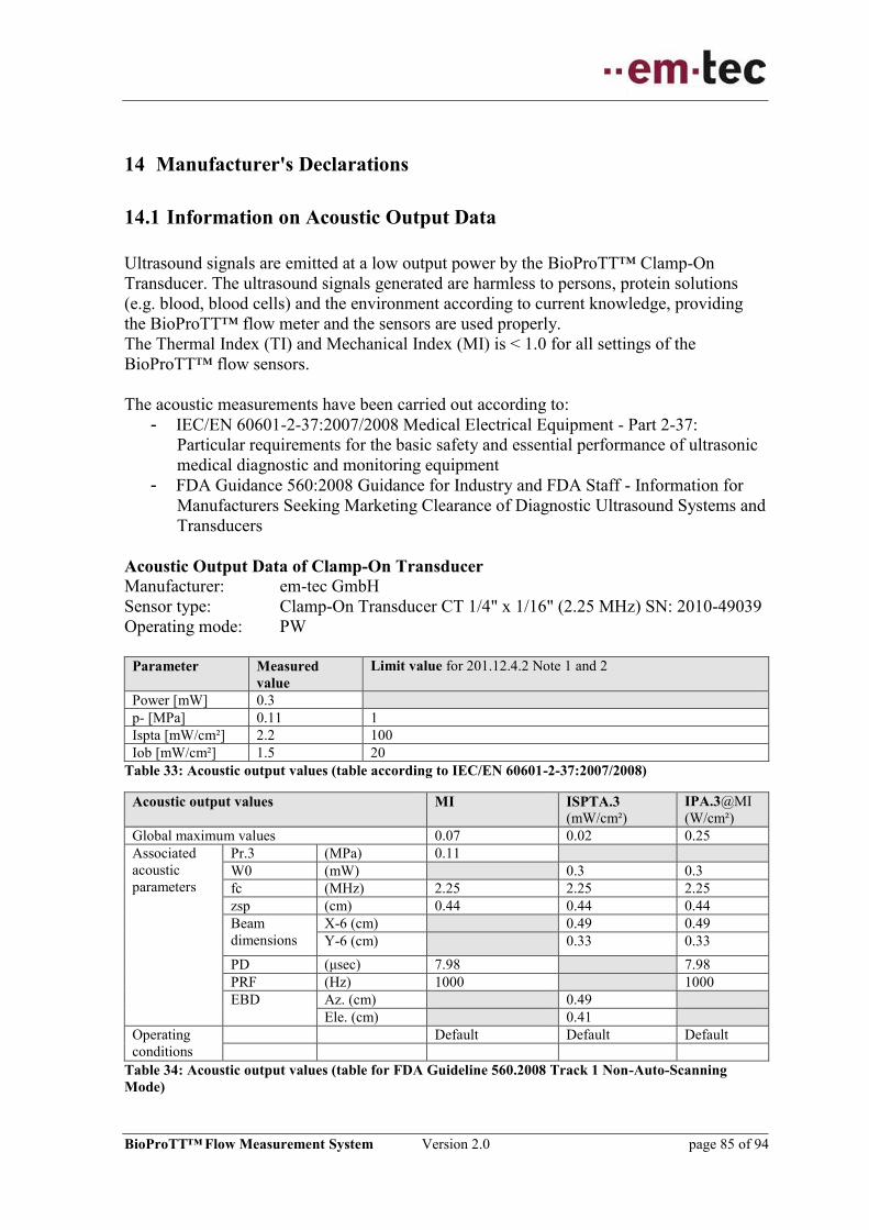
BioProTT™ Flow Measurement System Version 2.0 page 85 of 94
14 Manufacturer's Declarations
14.1 Information on Acoustic Output Data
Ultrasound signals are emitted at a low output power by the BioProTT™ Clamp-On
Transducer. The ultrasound signals generated are harmless to persons, protein solutions
(e.g. blood, blood cells) and the environment according to current knowledge, providing
the BioProTT™ flow meter and the sensors are used properly.
The Thermal Index (TI) and Mechanical Index (MI) is < 1.0 for all settings of the
BioProTT™ flow sensors.
The acoustic measurements have been carried out according to:
- IEC/EN 60601-2-37:2007/2008 Medical Electrical Equipment - Part 2-37:
Particular requirements for the basic safety and essential performance of ultrasonic
medical diagnostic and monitoring equipment
- FDA Guidance 560:2008 Guidance for Industry and FDA Staff - Information for
Manufacturers Seeking Marketing Clearance of Diagnostic Ultrasound Systems and
Transducers
Acoustic Output Data of Clamp-On Transducer
Manufacturer: em-tec GmbH
Sensor type: Clamp-On Transducer CT 1/4" x 1/16" (2.25 MHz) SN: 2010-49039
Operating mode: PW
Parameter Measured
value
Limit value for 201.12.4.2 Note 1 and 2
Power [mW] 0.3
p- [MPa] 0.11 1
Ispta [mW/cm²] 2.2 100
Iob [mW/cm²] 1.5 20
Table 33: Acoustic output values (table according to IEC/EN 60601-2-37:2007/2008)
Acoustic output values MI ISPTA.3
(mW/cm²)
IPA.3@MI
(W/cm²)
Global maximum values 0.07 0.02 0.25
Associated
acoustic
parameters
Pr.3 (MPa) 0.11
W0 (mW) 0.3 0.3
fc (MHz) 2.25 2.25 2.25
zsp (cm) 0.44 0.44 0.44
Beam
dimensions
X-6 (cm) 0.49 0.49
Y-6 (cm) 0.33 0.33
PD (μsec) 7.98 7.98
PRF (Hz) 1000 1000
EBD Az. (cm) 0.49
Ele. (cm) 0.41
Operating
conditions
Default Default Default
Table 34: Acoustic output values (table for FDA Guideline 560.2008 Track 1 Non-Auto-Scanning
Mode)
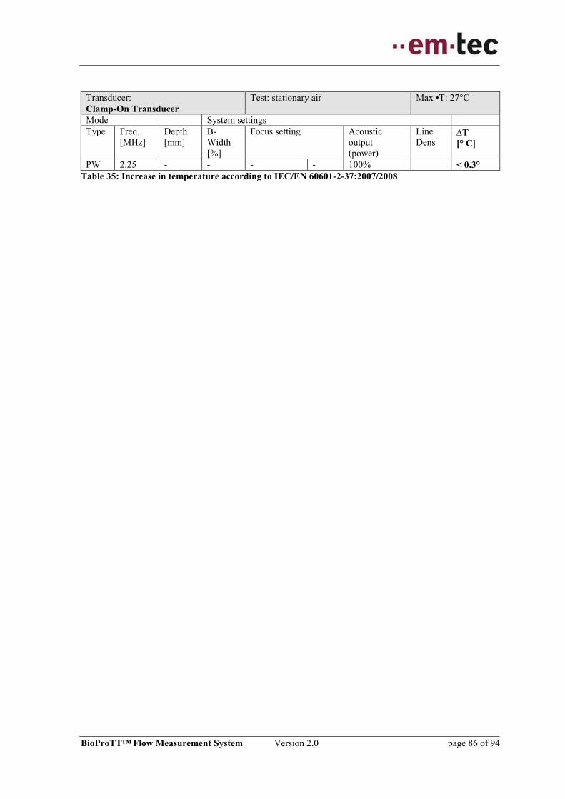
BioProTT™ Flow Measurement System Version 2.0 page 86 of 94
Transducer:
Clamp-On Transducer
Test: stationary air Max •T: 27°C
Mode System settings
Type Freq.
[MHz]
Depth
[mm]
B-
Width
[%]
Focus setting Acoustic
output
(power)
Line
Dens T
[° C]
PW 2.25 - - - - 100% < 0.3°
Table 35: Increase in temperature according to IEC/EN 60601-2-37:2007/2008

BioProTT™ Flow Measurement System Version 2.0 page 87 of 94
14.2 EU Declaration of Conformity

BioProTT™ Flow Measurement System Version 2.0 page 88 of 94
14.3 FCC Certificate of Compliance

BioProTT™ Flow Measurement System Version 2.0 page 89 of 94
15 Ordering Information for the BioProTT™ Flow Measurement
System and Accessories
Order Number Description
BioProTT™ Flow Meters
12214 BioProTT™ FlowTrack
Flow meter without display
12271 BioProTT™ FlowTrack plus
Flow meter with display as bench top variant
12565 BioProTT™ FlowTrack plus
Flow meter with display as panel mount variant
12390 BioProTT™ FlowTrack DINrail
Flow meter without display for DIN rail mounting
BioProTT™ Clamp-On Transducers,
Size: ID x WT in inch; one calibration table included, e.g. 20°C, water, PVC; up to 7
calibration tables possible
12386 BioProTT™ Clamp-On Transducer, 1/8” x 1/16”
12345 BioProTT™ Clamp-On Transducer, 11/64” x 3/64”
12344 BioProTT™ Clamp-On Transducer, 3/16” x 1/16”
12341 BioProTT™ Clamp-On Transducer, 1/4" x 1/16”
12342 BioProTT™ Clamp-On Transducer, 1/4" x 3/32”
12346 BioProTT™ Clamp-On Transducer, 3/8“ x 1/16”
12367 BioProTT™ Clamp-On Transducer, 3/8" x 3/32"
12607 BioProTT™ Clamp-On Transducer, 3/8" x 1/8"
12343 BioProTT™ Clamp-On Transducer, 1/2“ x 3/32”
12388 BioProTT™ Clamp-On Transducer, 1/2“ x 1/8”

BioProTT™ Flow Measurement System Version 2.0 page 90 of 94
Order Number Description
BioProTT™ Accessories
On request Factory calibration certificate
On request Ultrasonic Coupling Paste
On request RS 232 to USB adapter
12466 Extension cable 1 (IP50 rating at panel) – standard for
BioProTT™ FlowTrack DINrail.
The cable is compatible to all BioProTT™ flow meters.
12560 Extension cable 2 (IP68 [2 m, 24 h] rating at panel) – standard for
BioProTT™ FlowTrack plus (for panel mount).
The cable is compatible to all BioProTT™ flow meters.
On request Power supply for BioProTT™ flow meter with country specific
adaptors
On request Custom Calibration (additional table with “standard” parameters)
On request Customization of Clamp-On Transducer to fit custom tubing size
Table 36: Overview Order Numbers

BioProTT™ Flow Measurement System Version 2.0 page 91 of 94
16 Return Information and Declaration of Contamination
Because of legal regulations and for the safety of our employees and operating equipment, we need the
"Declaration of Contamination", with your signature, before your order can be handled. Please make
absolutely sure to include it with the shipping documents, or - even better - attach it to the outside of the
packaging.
Type of device, e.g. flow meter, sensor _________________ Serial number _______________
Relevant process data
Temperature / _________ [°C] Pressure / __________ [ Pa ]
Conductivity / _________ [ S ] Viscosity / __________ [mm /s]
Medium and warnings
Medium /
concentration
Identi-
fication /
CAS No
Flammable Toxic Corrosive Harmful/
Irritant
Other* Harmless
Process
Medium
Medium for
process cleaning
Returned
part cleaned with
* explosive; oxidizing; dangerous for the environment; biological risk; radioactive
Please tick should one of the above be applicable, include security sheet and, if necessary, special handling
instructions.
Reason for return:
Company contact data:
Company:
Contact person/department:
Address:
Fax / E-Mail
Reference No:
We hereby certify that the returned parts have been carefully cleaned. To the best of our knowledge they are
free from any residues in dangerous quantities.
_______________________________ __________________________________
(Place, Date) (Company stamp and signature)
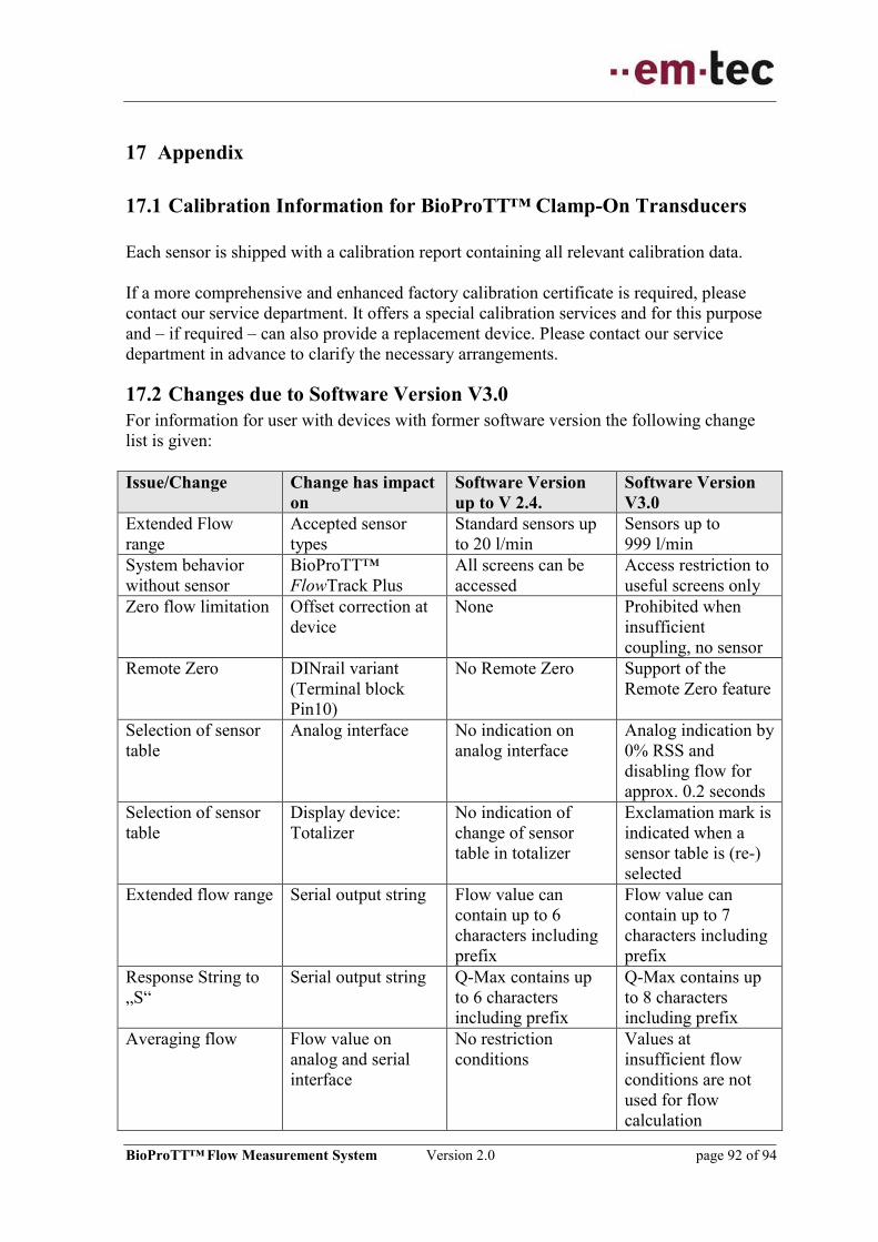
BioProTT™ Flow Measurement System Version 2.0 page 92 of 94
17 Appendix
17.1 Calibration Information for BioProTT™ Clamp-On Transducers
Each sensor is shipped with a calibration report containing all relevant calibration data.
If a more comprehensive and enhanced factory calibration certificate is required, please
contact our service department. It offers a special calibration services and for this purpose
and – if required – can also provide a replacement device. Please contact our service
department in advance to clarify the necessary arrangements.
17.2 Changes due to Software Version V3.0
For information for user with devices with former software version the following change
list is given:
Issue/Change Change has impact
on
Software Version
up to V 2.4.
Software Version
V3.0
Extended Flow
range
Accepted sensor
types
Standard sensors up
to 20 l/min
Sensors up to
999 l/min
System behavior
without sensor
BioProTT™
FlowTrack Plus
All screens can be
accessed
Access restriction to
useful screens only
Zero flow limitation Offset correction at
device
None Prohibited when
insufficient
coupling, no sensor
Remote Zero DINrail variant
(Terminal block
Pin10)
No Remote Zero Support of the
Remote Zero feature
Selection of sensor
table
Analog interface No indication on
analog interface
Analog indication by
0% RSS and
disabling flow for
approx. 0.2 seconds
Selection of sensor
table
Display device:
Totalizer
No indication of
change of sensor
table in totalizer
Exclamation mark is
indicated when a
sensor table is (re-)
selected
Extended flow range Serial output string Flow value can
contain up to 6
characters including
prefix
Flow value can
contain up to 7
characters including
prefix
Response String to
„S“
Serial output string Q-Max contains up
to 6 characters
including prefix
Q-Max contains up
to 8 characters
including prefix
Averaging flow Flow value on
analog and serial
interface
No restriction
conditions
Values at
insufficient flow
conditions are not
used for flow
calculation

BioProTT™ Flow Measurement System Version 2.0 page 93 of 94
Issue/Change Change has impact
on
Software Version
up to V 2.4.
Software Version
V3.0
RSS threshold for
insufficient coupling
Flow output due to
insufficient coupling
Hysteresis behavior
of RSS in range 50 to
60%
Fix threshold for
RSS of 50%, no
hysteresis
Additional
indication of invalid
flow values
Indication on digital
output
No indication Overflow indication
in serial string:
“-------“
Overflow condition: Indication on
display and digital
output
No indication Overflow indication
in serial string:
“^^^^^^^”
Underflow
condition:
Indication on display
and digital output
No indication Underflow
indication:
“vvvvvvv“ Table 37: Overview Changes from V2.4 to V3.0
17.3 Output Strings of V2.4 versus V3.0
Due to extend of flow range the string can handle flows of 6 characters with prefix instead
of 5 characters plus prefix.
Version Output String Examples V2.4 (and
lower)
Positive flow: “00 00 100 1.00 -16653 -16655 -16694 +30” <CR><LF>
Negative flow: “00 00 100 1.00 16720 16712 16732 +31” <CR><LF>
V3.0 Negative flow: “00 00 100 1.00 -16109 -16121 -16122 +35” <CR><LF>
Positive flow: “00 00 100 1.00 16072 16061 16054 +34” <CR><LF>
Large negative flow: “00 00 100 1.00 -100107 -100111 -100122 +35” <CR><LF>
Large positive flow: “00 00 100 1.00 100205 100208 100205 +34” <CR><LF>
Due to the extended flow value, the output string starts at the same position but is two
characters longer.
Version Output String Examples (Response on “S” command) V2.4 (and
lower)
“83599 3/8" x 3/32" PVC Water
23 °C 2 +10000” <CR><LF>
“ 59914 V2.4.0.1 ” <CR><LF>
V3.0 “83599 3/8" x 3/32" PVC Water
23 °C 2 10000” <CR><LF>
“ 59916 V3.0.0.0 ” <CR><LF>

BioProTT™ Flow Measurement System Version 2.0 page 94 of 94
Manufacturer:
em-tec GmbH
Lerchenberg 20
86923 Finning
Germany
Tel.: +49 (0) 8806 9236-0
Fax: +49 (0) 8806 9236-50
Internet: www.em-tec.de
E-Mail: [email protected]
© em-tec GmbH
All rights reserved, especially with respect to reproduction, distribution and translation. These
Operating Instructions or any part thereof must not be reproduced, saved, processed, duplicated or
distributed without the written consent of em-tec GmbH.
IFU BioProTT-en Version 2.0 Date: 2015-03-18