Embed Size (px)
Citation preview

OPERATING INSTRUCTIONS TREND SERIES
i
LIMITED WARRANTY
Helm Instrument Co., Inc. (”HELM”) hereby warrants that the instruments andsensors (collectively the ”Product”) manufactured by it and sold to customer, arefree from defects in material and/or workmanship under normal use subject to thefollowing conditions. This warranty shall not apply to any Product which has beensubjected to improper installation, misuse, negligence, accident, alteration, whereservice has been performed by other than an authorized Helm serviceman, orwhere the serial number has been defaced or altered. This warranty shall extendfor the one (1) year period from date of shipment from our factory or authorizeddealer, provided that the product is returned, freight prepaid, to Helm within theone (1) year warranty period within specific written authorization to performrepairs. Helm’s obligations and the exclusive remedy of customer under thiswarranty are limited to repairing or replacing any defective Product at noadditional charge and returning Product to customer freight paid. Repair partsand replacement Products shall be furnished on an exchange basis and shall beeither new or reconditioned. All replaced parts and Products shall become theproperty of Helm.
EXCEPT AS SPECIFICALLY STATED HEREIN, HELM MAKES NOWARRANTIES EXPRESSED OF IMPLIED, OF THIS PRODUCT INCLUDINGBUT NO LIMITED TO WARRANTIES OF MERCHANTABILITY OR FITNESSFOR A PARTICULAR PURPOSE, OR AS TO THE QUALITY, UTILITY ORPERFORMANCE, ALL QF WHICH ARE HEREBY EXPRESSLY EXCLUDED. INNO EVENT SHALL THE LIABILITY OF HELM EXCEED THE PURCHASEPRICE OF THIS PRODUCT. NOR SHALL HELM BE LIABLE FOR ANYDAMAGES WHATSOEVER, INCLUDING BUT NOT LIMITED TO SPECIAL,INDIRECT, INCIDENTAL OR CONSEQUENTIAL CHARGES, EXPENSE ORDAMAGES, ARISING OUT OF THE USE OR INABILITY TO USE THISPRODUCT OR FOR ANY CLAIM BY ANY OTHER PARTY.
Should you have any questions concerning this Warranty, you may contact Helmby writing or calling:
HELM INSTRUMENT COMPANY, INC.CUSTOMER SERVICE
361 WEST DUSSEL DRIVEMAUMEE, OHIO 43537
(41 9) 893-4356

OPERATING INSTRUCTIONS TREND SERIES
ii
EXPLANATION OF SYMBOLS
~
W
Alternating Currrent
Earth (ground) TERMINAL
On (Supply)
Off (Supply)
Caution, risk of electric shock
Caution (refer to accompanyingdocuments)

OPERATING INSTRUCTIONS TREND SERIES
a
Introduction ........................................................................................................................................................1Trend System Operation....................................................................................................................................1The Strain Gain Transducer Operation..............................................................................................................1Trend Loadgard Installation ...............................................................................................................................2Enviromental Conditions....................................................................................................................................2Strain Gain Installation And Wiring ....................................................................................................................2Sensor Wiring Connections ...............................................................................................................................2Instrument Power And Relay Wiring..................................................................................................................3Electrical Specifications .....................................................................................................................................3Replacement Fuses...........................................................................................................................................3Instrument Calibration........................................................................................................................................5Preliminary Calibration Adjustment Procedures ................................................................................................6Individual Channel Adjustments ........................................................................................................................6Manual Zero Adjust............................................................................................................................................6Gain Adjust ........................................................................................................................................................7Meter Calibrate Switches...................................................................................................................................8Setting Meter Calibrate Switches On Two Channel Systems ...........................................................................9Alarm Set Procedures......................................................................................................................................10Setting Capacity Alarm ....................................................................................................................................11Setting High - Low Tolerance Limits ................................................................................................................12Establishing Optimum Tolerance Settings.......................................................................................................12Job Data Control (Jdc).....................................................................................................................................13Initial Storing Of Capacity And Tolerance Settings..........................................................................................13Storing Of Target Loads ..................................................................................................................................13Testing For Open Job Number ........................................................................................................................14Calling Stored Job Data For Die Setup............................................................................................................14Front Panel Controls - Operating Instructions .................................................................................................15Three Position Function Selector.....................................................................................................................15Setup (Clear) Keyswitch Position ....................................................................................................................15Monitor Parts Keyswitch Positions...................................................................................................................16Alarm Set Status ..............................................................................................................................................17Digital Meter Display ........................................................................................................................................17Trend Display-Quality Window ........................................................................................................................18Recorder Output Jacks ....................................................................................................................................19Front Panel Push Buttons................................................................................................................................20
Alarm Reset..................................................................................................................................................20Capacity Alarms ...........................................................................................................................................20Strokes Per Minute.......................................................................................................................................20Tolerance Alarms .........................................................................................................................................20Reverse Load ...............................................................................................................................................20Target Load ..................................................................................................................................................20
Cleaning...........................................................................................................................................................21Computer Interface And Filter Card Wiring ...................................................................................... Appendix A
OPERATING INSTRUCTIONS TREND SERIES
1
INTRODUCTION
You have just purchased the most advanced load monitoring system available. In addition to this system,HELM INSTRUMENT CO., INC. manufactures a complete line of load monitoring control systems for useon metal stamping, forging, compaction and assembly presses; cold forming, cold heading, injection moldingand die cast machines.
Standard or custom transducers and load cells are available for in-die monitoring or transfer or progressivetooling. Easy to use software systems designed for your specific plantwide SPC programs are alsoavailable.
At HELM, quality is inherent not only in the design of our products but in the attitudes of our employees aswell. We're working together to give you the best. After all, that's what our business is all about - providinginnovative instrumentation to help make your manufacturing process more productive and your operationmore effective.
TREND SYSTEM OPERATION
The HELM TREND LOADGARD control system provides protection for the die, the product and the machinewith minimal operator involvement. The Loadgard takes a sample of the forming force of an ideal part,stores this level in memory and compares each subsequent force level against the ideal.
In addition to capacity alarms for overload protection, the TREND Loadgard features high and low tolerancelimits, set automatically for each channel based on a pre-established setting.
Digital meters display load, machine speed, alarm settings and capacity alarms. Machine stop is initiatedwhen an off tolerance part is produced.
THE STRAIN GAIN TRANSDUCER OPERATION
The basic function of the HT-400 Strain Gain is to detect the amount of the deflection imposed on the pressas parts are being formed. All Strain Gain sensors are matched to within 1% and therefore can be replacedwithout re-calibration of the machine.
The HT-400 Strain Gain sensors are mounted to strategic high stress areas of the machine frame. Signalsfrom these sensors are routed to the TREND Loadgard for processing. The HT-400 is capable of measuringeither a tension or compression signal.

OPERATING INSTRUCTIONS TREND SERIES
2
INSTALLATION GUIDELINES
TREND LOADGARD INSTALLATION
WARNING
If this unit is modified in a manner not specified by the manufacturer, protection provided may be impaired.Repair or calibration of this equipment is to be done by authorized personnel only. This unit contains noserviceable parts other than those outlined in this manual. Return unit to manufacturer for repair.
For purposes of safety, this unit is to be permanently installed. Electrical lines will be housed in conduit sothat wiring is not subject to mechanical stress. A means of electrical disconnect (switch or circuit breaker)shall be included in the permanent power installation. This disconnect device will be in close proximity to theequipment and within easy reach of the operator. The device will be clearly marked as the disconnect forthe equipment (ref. Drawing T-2227 Appendix A).
For best results, mount the TREND Loadgard at eye level and within operators' reach. Use the suppliedrubber shock mounts to isolate the unit from vibration. Care should be taken to insure that the instrumentchassis ground W is the same potential as the machine ground. See Mounting Detail Illustration inAppendix A.
ENVIROMENTAL CONDITIONS
This unit is designed for indoor use only. Operating temperature range is from 5ºC up to 55ºC.
STRAIN GAIN INSTALLATION AND WIRING
Specific sensor location and mounting instructions are described in the “Installing Strain Gain Transducers”manual. Refer to this manual for proper location and installation. Sensor nominal resistance values shouldcheck out in accordance with HELM drawing number T-2344-51 in Appendix A. For proper wiring, useseparate conduit or sealtite for transducer cables and avoid running these cables with any press control orhigh power motor circuits. Transducer cables should never be run near high voltage (220VAC, 440VAC)circuits.
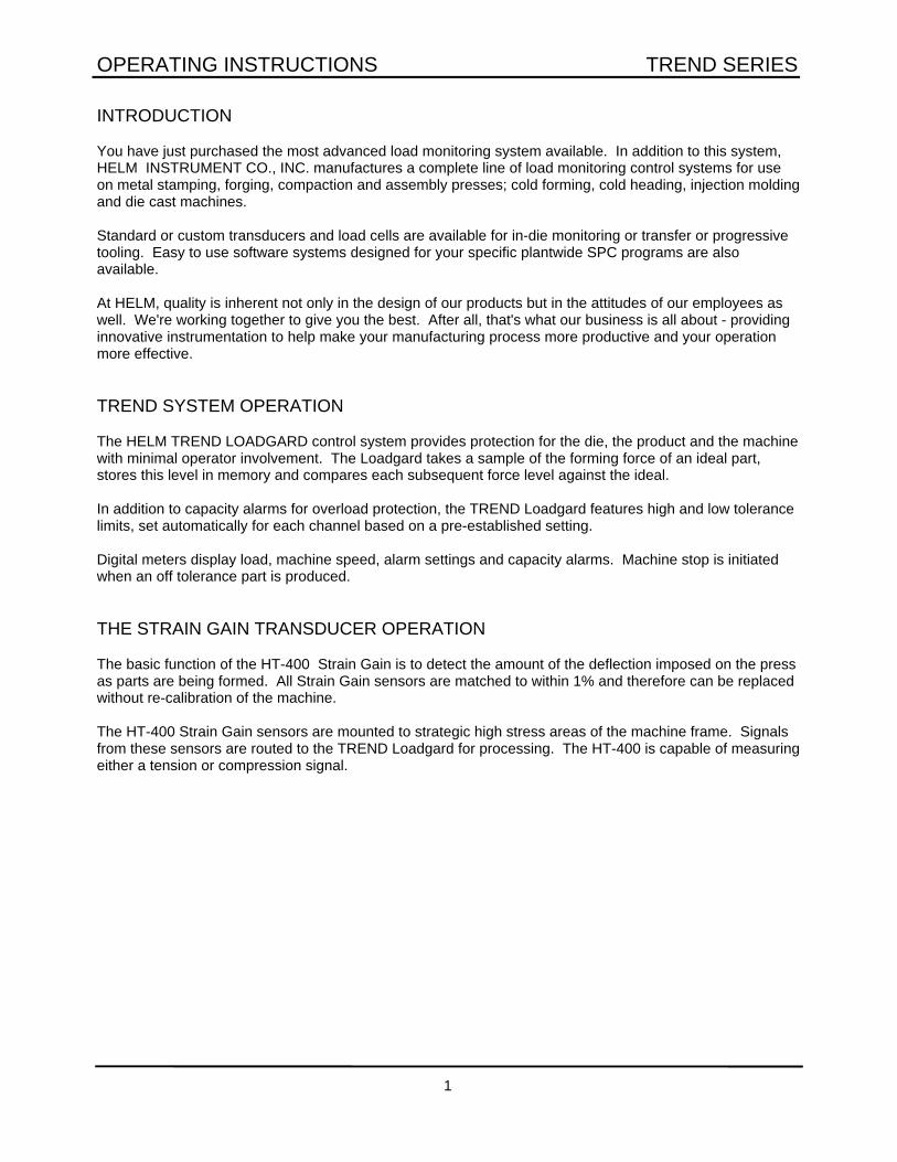
SENSOR WIRING CONNECTIONS
The Sensor Terminal Strips are located inside the box, above the circuit board card rack.NOTE: Always route power and sensor cables through proper holes as designated inside theLOADGARD enclosure.
TENSION COMPRESSION+G (gage positive) green black-G (gage negative) black green-S (signal negative) red red (shield) shield shield+S (signal positive) white white
OPERATING INSTRUCTIONS TREND SERIES
3
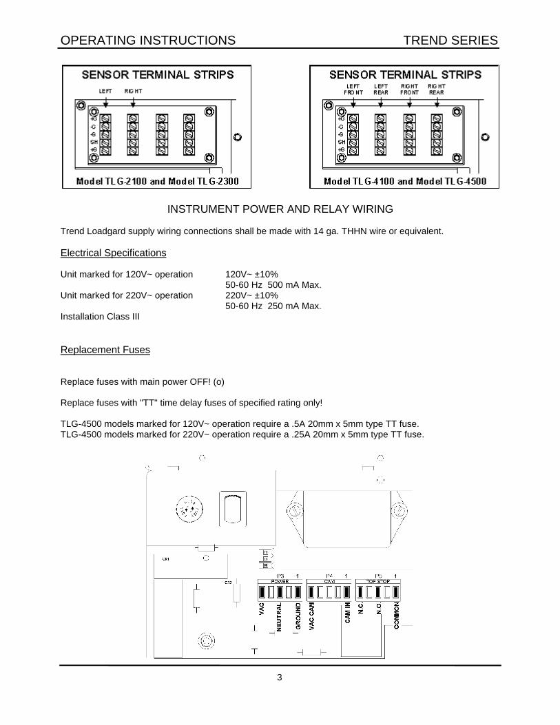
INSTRUMENT POWER AND RELAY WIRING
Trend Loadgard supply wiring connections shall be made with 14 ga. THHN wire or equivalent.
Electrical Specifications
Unit marked for 120V~ operation 120V~ ±10%50-60 Hz 500 mA Max.
Unit marked for 220V~ operation 220V~ ±10%50-60 Hz 250 mA Max.
Installation Class III
Replacement Fuses
Replace fuses with main power OFF! (o)
Replace fuses with "TT" time delay fuses of specified rating only!
TLG-4500 models marked for 120V~ operation require a .5A 20mm x 5mm type TT fuse.TLG-4500 models marked for 220V~ operation require a .25A 20mm x 5mm type TT fuse.

OPERATING INSTRUCTIONS TREND SERIES
4
A mechanical relay is provided to activate machine stop when an alarm condition occurs. This relay is wired“fail-safe” and will pass current through the normally closed and common contacts when the instrument isturned on and no alarms are tripped. Current rating for these contacts is 10 amps at 120VAC. Cam switchconnections are supplied, if applicable.
CARD RACK - Channel Boards
The steel cabinet (card rack) inside the instrument holds all the circuit boards. Slot #1 is reserved for theoptional computer interface card. Slot #2 contains the microprocessor board that controls all instrumentlogic. Slot #3 is open.
Slots #4 through 7 are reserved for channel boards. Refer to the illustrations below for the proper location ofeach channel board in your instrument(s).
Channel boards are interchangeable. Use the jumper plugs on the individualchannel boards for setting the proper channel board number.
NOTE: Jumpers are factory set prior to shipment. Adjust this jumper only ifyou switch channel board locations.

OPERATING INSTRUCTIONS TREND SERIES
5
INSTRUMENT CALIBRATION
This section details calibration procedures. If this system has been calibrated by a HELM Field ServiceEngineer or by the machine manufacturer, the calibration numbers will be noted on a tag inside theinstrument. Once calibrated, it is not necessary to re-calibrate unless the machine is moved, dismantled orotherwise structurally changed. If you have any questions or need a HELM Field Engineer for calibration,please contact our Field Service Department at 419-893-4356.
The illustration below details the locations of switches and potentiometers used during calibration.

OPERATING INSTRUCTIONS TREND SERIES
6
PRELIMINARY CALIBRATION ADJUSTMENT PROCEDURES
1. Turn function keyswitch to SETUP position.
2. Open enclosure door, turn power on.
3. Set MONITOR/CALIBRATE switch, located on inside of door, to the CALIBRATE position.
INDIVIDUAL CHANNEL ADJUSTMENTS
MANUAL ZERO ADJUST
1. Push AUTO ZERO switch to the OFF (back) position.
2. Pull CALIBRATION switch to the OFF (forward) position.
3. Adjust the ZERO BALANCE
The zero balance (BALANCE ADJUST) controls are the smallmulti-turn potentiometers at the extreme right of each channelboard.
Watch the outside meter and turn the BALANCE ADJUSTcontrol of the first channel board until the meter displays allzeros. Repeat for all channels.
NOTE: On models TLG-4100 & TLG-2100, push LEFT or RIGHT DISPLAY button to display individualchannel readings.

OPERATING INSTRUCTIONS TREND SERIES
7
GAIN ADJUST
The GAIN ADJUST control is a small multi-turn control located on the extreme left of each channel board.This control is used to adjust the instrument to display the proper CAL (calibration) number on the digitalmeter(s).
During normal operation, Auto Zero and Calibration switches must be in the forward position.Monitor/Calibrate switch must be in Monitor position.
1. Push CALIBRATION SWITCH to the ON (back)position. This switch puts the CAL resistor(simulated load) across the sensor for that channel.
2. Set the GAIN ADJUSTMENT
If the press has been calibrated, use the CALnumbers that are recorded for each channel. If thepress has not been calibrated, use 50 as atemporary cal number.
Watch the digital meter and turn the GAIN ADJUSTcontrol until the meter displays the correct CALnumber. Repeat for all channels.
3. Turn AUTO ZERO on by moving the AUTOZERO switch to the ON (forward) position. PullCALIBRATION switch to the OFF (forward) positionto remove simulated load.
4. Set MONITOR/CALIBRATE switch back to“MONITOR” position.
OPERATING INSTRUCTIONS TREND SERIES
8
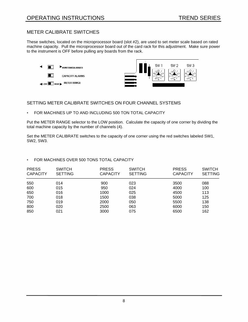
METER CALIBRATE SWITCHES
These switches, located on the microprocessor board (slot #2), are used to set meter scale based on ratedmachine capacity. Pull the microprocessor board out of the card rack for this adjustment. Make sure powerto the instrument is OFF before pulling any boards from the rack.
SETTING METER CALIBRATE SWITCHES ON FOUR CHANNEL SYSTEMS
• FOR MACHINES UP TO AND INCLUDING 500 TON TOTAL CAPACITY
Put the METER RANGE selector to the LOW position. Calculate the capacity of one corner by dividing thetotal machine capacity by the number of channels (4).
Set the METER CALIBRATE switches to the capacity of one corner using the red switches labeled SW1,SW2, SW3.
• FOR MACHINES OVER 500 TONS TOTAL CAPACITY
PRESS SWITCH PRESS SWITCH PRESS SWITCHCAPACITY SETTING CAPACITY SETTING CAPACITY SETTING
550 014 900 023 3500 088600 015 950 024 4000 100650 016 1000 025 4500 113700 018 1500 038 5000 125750 019 2000 050 5500 138800 020 2500 063 6000 150850 021 3000 075 6500 162

OPERATING INSTRUCTIONS TREND SERIES
9
METER CALIBRATE SWITCHES (cont.)
SETTING METER CALIBRATE SWITCHES ON TWO CHANNEL SYSTEMS
• FOR MACHINES UP TO AND INCLUDING 250 TONS TOTAL CAPACITY
Put the METER RANGE selector to the LOW position. Calculate the capacity of one side by dividing thetotal machine capacity by the number of channels (2).
Set the METER CALIBRATE switches to the capacity of one side using red switches labeled SW1, SW2 andSW3.
EXAMPLE: For a 100 ton machine rated at 50 tons per side, set switches to 050 by setting left switch(SW1) to 0, middle switch (SW2) to 5 and right switch (SW3) to 0. Re-install board.
• FOR PRESS OVER 250 TONS TOTAL CAPACITY
Put the METER RANGE selector to the HIGH position. Set METER CALIBRATE switches based on thefollowing table.
PRESS SWITCH PRESS SWITCH PRESS SWITCHCAPACITY SETTING CAPACITY SETTING CAPACITY SETTING
300 015 600 030 900 045350 018 650 033 950 048400 020 700 035 1000 050450 023 750 038 1500 075500 025 800 040 2000 100550 028 850 043 2500 125
3000 150
OPERATING INSTRUCTIONS TREND SERIES
10
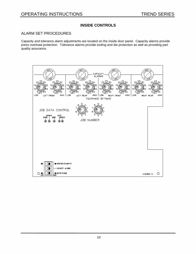
INSIDE CONTROLS
ALARM SET PROCEDURES
Capacity and tolerance alarm adjustments are located on the inside door panel. Capacity alarms providepress overload protection. Tolerance alarms provide tooling and die protection as well as providing partquality assurance.

OPERATING INSTRUCTIONS TREND SERIES
11
SETTING CAPACITY ALARM
1. Turn Function Selector to SETUP position.
2. Open enclosure door and locate slideswitches on inside door.
3. Slide top switch on inner door to CALIBRATEposition (right) and center switch marked CAPACITYALARMS to the right.
4. Unlock Capacity Alarm control knob by turning the locking ring counter clockwise.
5. Calculate capacity alarm for each channel by dividing total press capacity by the number of channels onthe instrument. Divide by four (4) for four channel systems. Divide by two (2) for two channel systems.
6. Watch the digital meter(s) and adjust capacity for each channel. Models 2100 & 4100 use the LEFT orRIGHT DISPLAY button for displaying individual channel settings on the digital meter.
7. Turn locking ring clockwise to lock Capacity Alarm sets.
8. Return top and center slide switches to left position. For normal operation, these two slide switches mustbe in the left position.
EXAMPLE: For a press with a four channel system and a total rated capacity of 500 tons, calculate the perchannel capacity. Divide press capacity by the number of channels (500/4 = 125 per corner). Turn thecontrol to make the meter display 125 tons.
OPERATING INSTRUCTIONS TREND SERIES
12
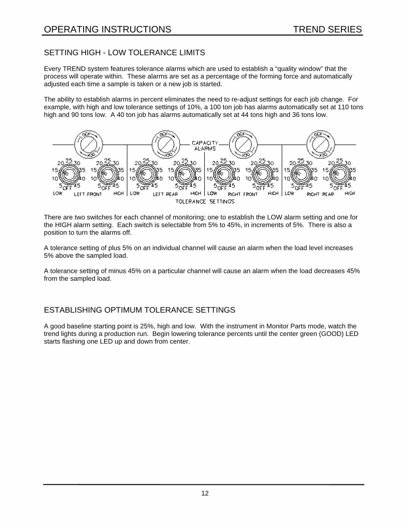
SETTING HIGH - LOW TOLERANCE LIMITS
Every TREND system features tolerance alarms which are used to establish a “quality window” that theprocess will operate within. These alarms are set as a percentage of the forming force and automaticallyadjusted each time a sample is taken or a new job is started.
The ability to establish alarms in percent eliminates the need to re-adjust settings for each job change. Forexample, with high and low tolerance settings of 10%, a 100 ton job has alarms automatically set at 110 tonshigh and 90 tons low. A 40 ton job has alarms automatically set at 44 tons high and 36 tons low.
There are two switches for each channel of monitoring; one to establish the LOW alarm setting and one forthe HIGH alarm setting. Each switch is selectable from 5% to 45%, in increments of 5%. There is also aposition to turn the alarms off.
A tolerance setting of plus 5% on an individual channel will cause an alarm when the load level increases5% above the sampled load.
A tolerance setting of minus 45% on a particular channel will cause an alarm when the load decreases 45%from the sampled load.
ESTABLISHING OPTIMUM TOLERANCE SETTINGS
A good baseline starting point is 25%, high and low. With the instrument in Monitor Parts mode, watch thetrend lights during a production run. Begin lowering tolerance percents until the center green (GOOD) LEDstarts flashing one LED up and down from center.

OPERATING INSTRUCTIONS TREND SERIES
13
JOB DATA CONTROL (JDC)
The JED feature provides memory storage of up to 100 different job numbers per LOADGARD. Thefollowing data is stored for each job:
• Capacity alarm settings• Tolerance alarm settings• Target (optimum) load values
INITIAL STORING OF CAPACITY AND TOLERANCE SETTINGS
1. Put JDC switch in manual mode.
2. Set selector switches to desired job number (0-99).
3. Check capacity and tolerance settings; readjust if necessary.
4. Press STORE button
5. Green LED on JDC panel will flash, indicating data is being stored.
6. To over-ride and store new settings, follow steps 1-5.
STORING OF TARGET LOADS
1. Put JDC switch in Auto mode.
2. Turn front panel keyswitch to monitor parts mode.
3. TARGET values are automatically stored during initial setup when front panel keyswitch is turned to Monitor Parts mode. The TARGET value is current peak tonnage as displayed on digital meters.
4. To over-ride and store new TARGET values, put JDC switch in Auto Mode and press store button. Peak loads as displayed on the digital meters will be stored as new target loads.
5. Green LED will flash, indicating data is being stored.
Capacity and Tolerance settings are stored in MANUAL mode. Target loads are stored in AUTOmode.

OPERATING INSTRUCTIONS TREND SERIES
14
JOB DATA CONTROL (cont.)
TESTING FOR OPEN JOB NUMBER
1. Put JDC switch in AUTO mode.
2. Select job number.
3. Yellow LED will flash if job number is available.
CALLING STORED JOB DATA FOR DIE SETUP
1. Select job number to be recalled.
2. Put JDC switch in auto mode.
3. Capacity and Tolerance settings are activated for first hit protection.
4. Press Target Load button on front panel to display target values on each channel. Job number is displayed on center meter.
5. With front panel function selector switch in SETUP mode, Trend columns are used to indicate if the current peak load value is above or below the stored target value.
OPERATING INSTRUCTIONS TREND SERIES
15
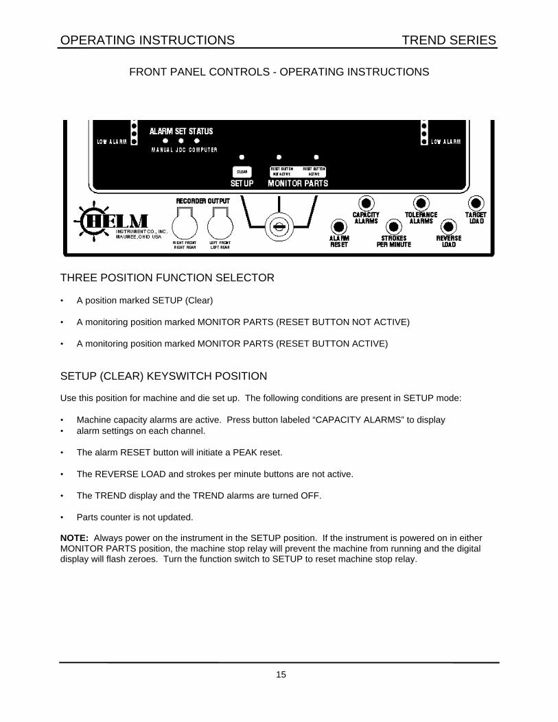
FRONT PANEL CONTROLS - OPERATING INSTRUCTIONS
THREE POSITION FUNCTION SELECTOR
• A position marked SETUP (Clear)
• A monitoring position marked MONITOR PARTS (RESET BUTTON NOT ACTIVE)
• A monitoring position marked MONITOR PARTS (RESET BUTTON ACTIVE)
SETUP (CLEAR) KEYSWITCH POSITION
Use this position for machine and die set up. The following conditions are present in SETUP mode:
• Machine capacity alarms are active. Press button labeled “CAPACITY ALARMS” to display• alarm settings on each channel.
• The alarm RESET button will initiate a PEAK reset.
• The REVERSE LOAD and strokes per minute buttons are not active.
• The TREND display and the TREND alarms are turned OFF.
• Parts counter is not updated.
NOTE: Always power on the instrument in the SETUP position. If the instrument is powered on in eitherMONITOR PARTS position, the machine stop relay will prevent the machine from running and the digitaldisplay will flash zeroes. Turn the function switch to SETUP to reset machine stop relay.

OPERATING INSTRUCTIONS TREND SERIES
16
MONITOR PARTS KEYSWITCH POSITIONS
During production, the keyswitch should be in one of these MONITOR PARTS positions.
Once the machine is set up and producing good parts, turn the switch to one of these positions. Theinstrument will take a sample of the forming loads and store this sample in memory. Each subsequent hit iscompared to this sample. The TREND lights will display any changes in the forming loads.
Tolerance alarms are automatically adjusted when this sample is taken. Any load change that meets orexceeds the tolerance settings will cause an alarm condition and activate the machine stop relay.
In Monitor Parts/Reset Not Active, the ALARM RESET button is inactive and the keyswitch must be turnedto Reset Active before alarms can be reset.
The following conditions are present in MONITOR PARTS position:
• Capacity alarms are active.
• The TREND display and the TREND alarms on ON.
• All front panel switches are active.
NOTE: The sample loads are erased whenever the function switch is turned to the SETUP position. Tostop the machine for a break, leave the instrument in MONITOR PARTS-RESET ACTIVE position. Whenrestarting the machine, push ALARM RESET button to clear any alarms.

OPERATING INSTRUCTIONS TREND SERIES
17
ALARM SET STATUS
LED's located on front panel indicate statusof instrument capacity and tolerance alarmsettings as follows:
• MANUAL JDC and Computer controls are inactive. Alarm limits adjusted based on switch settings inside door.
• JDC Alarm limits adjusted based on settings stored in Job Data memory circuit. With JDC feature active, adjustments made on capacity or tolerance alarm switches have no effect.
• COMPUTER When interfaced with computer or PLC, JDC job numbers and alarm limits can be sent to the LOADGARD from remote location. With computer set limits, JDC and manual selector switches are inactive and computer has control.
DIGITAL METER DISPLAY
During normal operation, the center digital meter displays the total tonnage being applied on the press. Themeter is also used for displaying total reverse (snap-thru) loads and machine speed (SPM). On single digitalmeter instruments, this center meter is used to display capacity alarm settings and high and low tolerancesetting for each channel.
Models TLG-4500 & TLG-2300 have additional digital meters for displaying the load and alarm settings onindividual channels.
Models TLG-4100 & TLG-2100 use the Left and Right Display buttons for displaying individual channelDISPLAY button for additional meter display.
OPERATING INSTRUCTIONS TREND SERIES
18
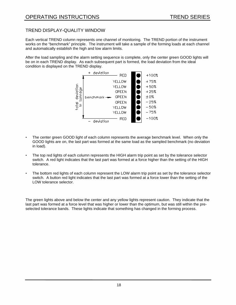
TREND DISPLAY-QUALITY WINDOW
Each vertical TREND column represents one channel of monitoring. The TREND portion of the instrumentworks on the “benchmark” principle. The instrument will take a sample of the forming loads at each channeland automatically establish the high and low alarm limits.
After the load sampling and the alarm setting sequence is complete, only the center green GOOD lights willbe on in each TREND display. As each subsequent part is formed, the load deviation from the idealcondition is displayed on the TREND display.
• The center green GOOD light of each column represents the average benchmark level. When only theGOOD lights are on, the last part was formed at the same load as the sampled benchmark (no deviationin load).
• The top red lights of each column represents the HIGH alarm trip point as set by the tolerance selectorswitch. A red light indicates that the last part was formed at a force higher than the setting of the HIGHtolerance.
• The bottom red lights of each column represent the LOW alarm trip point as set by the tolerance selectorswitch. A button red light indicates that the last part was formed at a force lower than the setting of theLOW tolerance selector.
The green lights above and below the center and any yellow lights represent caution. They indicate that thelast part was formed at a force level that was higher or lower than the optimum, but was still within the pre-selected tolerance bands. These lights indicate that something has changed in the forming process.

OPERATING INSTRUCTIONS TREND SERIES
19
RECORDER OUTPUT JACKS
Each TREND instrument has one or two dual circuit jacks for use with HELM Ramcorder or for output to astrip chart recorder.
Corner or Side Capacity level 2 Channel systems: Ring = Left Tip = Rightat each jack is 2.66 volts 4 Channel systems: Tip = Rear Ring = Front
Waveform recordings provide an analytical method of determining the force being developed throughout theentire stroke of the machine. Each die has its own unique signature, similar to an electro-cardiogram.Analyzing each of the subtle peak forces developed during the stamping process and comparing currentsignatures to previously recorded masters can be an aid in diagnosing or forming of die problems.
Product quality and press speeds are greatly enhanced after making and analyzing waveformrecordings. Many stampers make recordings as a routine part of their start-up procedures whenworking with a new or modified die, creating a history of recordings for each job.

OPERATING INSTRUCTIONS TREND SERIES
20
FRONT PANEL PUSH BUTTONS
ALARM RESET
Pressing this switch initiates a Peak reset for any alarm condition. This switch is only active when keyswitchis in SETUP or MONITOR PARTS RESET ACTIVE position.
CAPACITY ALARMS
Press the CAPACITY ALARMS button to any operating mode to display the capacity alarm setting on eachchannel. On single meter systems, press and hold the appropriate channel display button.
STROKES PER MINUTE
SPM is calculated and displayed when function keyswitch is in Monitor Parts position. While the machine isproducing parts, press and hold STROKES PER MINUTE button to display machine operating speed oncenter meter. Two machine cycles are required before SPM is displayed.
TOLERANCE ALARMS
Press the TOLERANCE ALARMS button to display high and low tolerance setting. The first two digitsrepresent the high tolerance setting; the second 2 digits represent the low tolerance setting. A display of2010 represents tolerance settings of 20% high and 10% low. On single meter instruments press and holdthe appropriate DISPLAY button.
REVERSE LOAD
With function selector in Monitor Parts position, the reverse (snap-thru) tonnage imposed on each channelplus total machine is displayed when this button is pressed.
TARGET LOAD
When using Job Data Control (JDC) feature, the TARGET LOAD for each channel (and total) is displayedwith this push button.

OPERATING INSTRUCTIONS TREND SERIES
21
CLEANING
External cleaning to this unit is to be with a cleancloth moistened with warm water and milddetergent only. The unit should be wiped dry thenallowed to air dry before returning to service.
Internal printed circuit board cleaning isaccomplished by removing individual boards andcleaning with an approved printed circuit boardcleaner. Dry boards are to be replaced beforereturning unit to service.
All cleaning is to be done with mainpower OFF!

OPERATING INSTRUCTIONS TREND SERIES
A

OPERATING INSTRUCTIONS TREND SERIES
B

OPERATING INSTRUCTIONS TREND SERIES
C

OPERATING INSTRUCTIONS TREND SERIES
D

OPERATING INSTRUCTIONS TREND SERIES
E
COMPUTER INTERFACE AND FILTER CARD WIRING
The computer interface card Model EIC plugs into Slot #1 of the card rack.
Mount the filter board on the inside panel marked “DO NOT REMOVE”. Use existing thumbwheel screws onleft side of panel. Remove the top two screws and attach filter board on top of panel as shown below.
Route computer cable into instrument enclosure through hole marked “For Interface Cables” and wireconnector P4 on filter card per wiring diagram on following page.

OPERATING INSTRUCTIONS TREND SERIES
F
DESCRIPTION OF MULTI I/O FILTER CARD
1. Computer or PLC can be either 422 or 232 communications.
Connections for 422 communications:
J22 on filter card should be jumpered across pins 2 and 3.
The cable coming from the EIC card plugs into J2 and J3 on the filter card.
The connector with the black and green wires plugs into J2 with the black wire on in 1 of J2.The connector with red and white wires plugs into J3 with the white wire on pin of J3.
The connector for computer hook-up is J1.
Connections for 232 communications:
J22 on filter card should be jumpered across pins 1 and 2.
The cable from the EIC card plugs into J2 and J3 on the filter card.
The connector with the black and green wires plug into J3 with the green wire on pin 1 of J3.The connector with red and white wires plug into J2 with the red wire on pin of J2.
The connector for computer hook-up is J4.
2. J14 is the connector for the sine-cosine resolver input.
Refer to drawing B10W996-1 for wiring detail.
3. There is a 422 to TTL converter on the card. 422 plugs into J8 and the TTL connects to J9.The normal operation of J19 should be jumpered across pins 2 and 3.
4. There is another port which can be either TTL to 422 or TTL to 232. The TTL plugs into J11. Fornormal operation, J20 will be jumpered across pins 2 and 3. The standard set-up will be for TTL422 communications with U6 installed and U7 removed. In order to have TTL to 232, you mustinstall U7 and remove U6.
5. J12 is the user connector for LDT and analog resolver connections. J17 is the connector for +and 15v power to LDT's.
6. There are two cables which plug into J16 and J18 on the card. These two cables are power for thefilter card. J16 is + and -15v. J18 is +5v and ground.
For normal 422 communications, the following settings apply:J19 jumpered between pins 2 and 3J20 jumpered between pins 2 and 3J22 jumpered between pins 2 and 3U7 should be pulled out

OPERATING INSTRUCTIONS TREND SERIES
G

OPERATING INSTRUCTIONS TREND SERIES
H

OPERATING INSTRUCTIONS TREND SERIES
I
Model TLG-8000
This appendix describes additional operating instructions for the standard TLG-8000 and TLG-8000DP withCam Limit Switch. Refer to drawings T-2435-42 and T-2435-41 following is appendix.

OPERATING INSTRUCTIONS TREND SERIES
JAppendix C: TLG-8000 Operation Guidelines

OPERATING INSTRUCTIONS TREND SERIES
KAppendix C: TLG-8000 Operation Guidelines

OPERATING INSTRUCTIONS TREND SERIES
L
TLG System Troubleshooting Guide
The following system set-up conditions should be verified prior to proceeding to block diagrams. See pageslisted below, in parenthesis, in this manual for switch location in instrument.
1. Unit powered up.
2. 110V power supplied to unit (page 3).
3. Monitor/Calibrate switch in left (monitor) position (page 7).
4. Capacity alarm switch in left (off) position (page 11).
5. Auto Zero switch on each channel board in forward (on) position (pages 6-7).
6. Calibrate switch on each channel board in forward (off) position (pages 6-7).
7. If any of the above switches are in the wrong position, correct the situation and returnbypass/monitor switch to left (bypass) position (page 15).
8. If problems still exists, continue to next page for list of specific problems.

OPERATING INSTRUCTIONS TREND SERIES
M
TLG Unit Voltage Checks
-9 pin connector located under “Do Not Remove” plate, upper LH Corner
Pin Satisfactory Voltage Range
Brown -3.8 to -4.2 volts
Red -3.8 to -4.2 volts
Orange +3.8 to +4.2 volts
Yellow -11.5 to -12.5 volts
Green +11.5 to +12.5 volts
Blue +3.8 to +4.2 volts
Grey 0 volts
White +4.75 to +5.25 volts
Miscellaneous Troubleshooting Specifications
HT-400 Sensor Ohm Readings
Green - Black 350 ohms
Red - White 350 ohms
All other color combinations 266 ohms
All color to Ground open
Shield to Ground open
OPERATING INSTRUCTIONS TREND SERIES
N
OPERATING INSTRUCTIONS TREND SERIES
O

OPERATING INSTRUCTIONS TREND SERIES
P

OPERATING INSTRUCTIONS TREND SERIES
Q
OPERATING INSTRUCTIONS TREND SERIES
R
OPERATING INSTRUCTIONS TREND SERIES
S

OPERATING INSTRUCTIONS TREND SERIES
T
PROBLEM POSSIBLE CAUSE REMEDY
No front panel indications Fuse blown.Power source.
Replace fuse.Check power.
Display flashes zeroes. Instrument turned off/on with functionswitch in Monitor Parts position.
Reset instrument by turning functionselector to Standby/Clear.
Bypass/Clear LED flashing.Meter display off.
Monitor/Calibrate switch (inside door)in calibrate position.
Set switch to Monitor (left) position.
Trend lights do not change.Meter does not display SPM orTolerance settings.
Function switch in Bypass position. Turn function switch to Monitor Partsto activate auto-timing for Strokes perminute.
High or Low Tolerance Alarms do notstop press.
Tolerance settings in OFF position. Select tolerances from 5% to 45% toactivate tolerance alarms.
Alarms will not reset. Function selector in MonitorParts/Reset not Active.
Possible open gage wire.
Turn function keyswitch to ResetActive.
Check strain gage wiring andconnections.
Tolerance alarms stop machinebefore tolerance setting is reached.
Capacity alarms settings have beenactivated.
Check Capacity Alarm Sets.Reset capacity alarms if required.
Alarms are fired or monitor tries tosample when machine is not running.
Strain Gain wires are run in conduitwith high voltage wires.
Route sensor wires in separateconduit.
Display will not zero or unusualnumbers are displayed.
Switches on individual channel boardsare improperly set.
Move all channel board switches toforward position.
Display does not zero when RESETbutton is pressed.
Normal condition in Monitor Partsposition. Display will zero only whenresetting alarm condition.
With function switch in Standby, peakload display is reset. In Monitor Parts,display is not reset when RESET ispressed.
Meter display off. Press/Machine willnot run.
Instrument turned off/on with functionswitch in Monitor parts position.
Check power.
Reset instrument by turning functionswitch to Standby/Clear then toMonitor Parts.
TREND alarms lit, machine machinecontinues to run.
Top stop wires are jumped out orpress is being operated in inch mode.
Check wiring. Operate in run mode.

OPERATING INSTRUCTIONS TREND SERIES
U