Embed Size (px)
Citation preview
EN
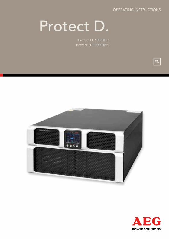
Protect D.Protect D. 6000 (BP)
Protect D. 10000 (BP)
OPerating instructiOns

2
3
thank you for purchasing the Protect D. uPs from aeg Power solutions.
the following safety precautions are an important part of these operating
instructions. they are designed to help you avoid problems caused by
operating errors and to protect you against any possible hazards. Please
read these instructions carefully before using the product for the first time!
4
Contents
1. notes on these operating instructions ............................................. 6
2. General Information .......................................................................... 8
2.1 technology ........................................................................................................8
2.2 system description ............................................................................................9
2.3 technical data .................................................................................................11
3. safety Regulations ........................................................................... 16
3.1 general safety instructions .............................................................................16
3.2 safety instructions for the Protect D. .............................................................16
3.3 ce certificate ...................................................................................................20
4. Installation ........................................................................................ 21
4.1 unpack and check ...........................................................................................21
4.2 installation ........................................................................................................23
4.3 assembly ..........................................................................................................23
5. overview of connections, operating / display elements ................ 26
5.1 Front view ........................................................................................................26
5.2 rear-panel view (connections): .......................................................................28
6. electrical connection ........................................................................ 31
6.1 safety of personnel ........................................................................................32
6.2 connection cross-section and fuses ...............................................................32
6.3 Mains and consumer connection ...................................................................34
6.4 contacting the battery modules ....................................................................36
6.4.1 connecting the internal battery ............................................................36
6.4.2 connecting external battery extension(s) .............................................39
7. operation Mode and operating ..................................................... 42
7.1 First start-up .....................................................................................................42
7.1.1 switching on the uPs .............................................................................42
7.1.2 switching off the uPs ............................................................................42
7.2 usage table ......................................................................................................43
7.2.1 Overview .................................................................................................43
7.2.2 indicators (LeDs) .....................................................................................43
7.2.3 Operating keys (navigation) ..................................................................44
7.3 Display (Main Menu) .......................................................................................45
7.3.1 uPs status-display ..................................................................................45
5
7.3.2 event log .................................................................................................49
7.3.3 Measurements ........................................................................................50
7.3.4 control ....................................................................................................50
7.3.5 identification ...........................................................................................51
7.3.6 settings ...................................................................................................51
8. Interfaces and communication ........................................................ 56
8.1 rs232 and usB computer interfaces .............................................................56
8.2 communications slot ......................................................................................56
8.3 shutdown and uPs management software ..................................................57
8.4 ePO (emergency Power off) .........................................................................58
8.5 change-over contact ......................................................................................59
9. troubleshooting ............................................................................... 60
9.1 Malfunctions ....................................................................................................60
9.1.1 alarm / error messages .........................................................................61
10. Parallel operation .......................................................................... 65
10.1 Function .........................................................................................................65
10.2 installation / connection of parallel field operation ...................................66
11. Maintenance .................................................................................. 67
11.1 charging the battery .....................................................................................67
11.2 Maintenance checks......................................................................................67
11.2.1 Visual check ...........................................................................................67
11.2.2 Battery check ........................................................................................68
11.2.3 Ventilator check ....................................................................................68
11.3 Battery replacement .....................................................................................68
12. storage, Dismantling and Disposal ............................................... 70
12.1 storage ..........................................................................................................70
12.2 Dismantling ....................................................................................................70
12.3 Disposal .........................................................................................................70
13. Appendix ....................................................................................... 72
13.1 technical terminology ...................................................................................72
13.2 Keyword register ..........................................................................................74
13.3 notes .............................................................................................................75
6
ObligatiON tO PrOviDE iNstructiONs
these operating instructions are designed to help you properly and safely install
and operate the following uninterruptible Power supply (uPs) systems: Protect
D. 6000 and Protect D. 10000, as well as the corresponding external battery units,
Protect D. 6000 BP and Protect D. 10000 BP, hereinafter collectively referred to as
Protect D. this operating instructions contain important information on avoiding
hazards.
PlEasE rEaD thEsE iNstructiONs carEfully bEfOrE
first usE!
these operating instructions are part of the Protect D.
the operator of this device is required to make these operating instructions
openly available to any person transporting, installing, servicing or performing
any other work on the Protect D.
valiDity
these operating instructions comply with the current technical specifications of
the Protect D. at the time of publication. the contents do not constitute a contract
and are for informational purposes only.
WarraNty aND liability
We reserve the right to make any changes to the information in this operating
manual, with respect to the specifications and the operating instructions in
particular, at any time.
complaints about delivered goods must be submitted within eight days of receipt,
along with the packing slip. Later claims will not be accepted.
any damage incurred due to non-compliance with these instructions (including
damage to the warranty seal) will void the warranty. aeg accepts no liability
for consequential damages. aeg will rescind all obligations, such as warranty
agreements, service contacts, etc. without prior notice in the event that any spare
parts other than original aeg spare parts or those purchased by aeg are used for
maintenance and repair.
1. notes on tHese oPeRAtInG InstRUCtIons
7
haNDliNg
the Protect D. is designed and constructed so that all of the steps that need to
be taken for its installation and operation can be done without having to open the
device. any maintenance or repairs are to be performed by qualified technicians
only.
illustrations are included to make certain steps clearer and easier to understand.
if there is any potential danger to personnel or equipment while performing
certain work, these activities are accompanied by pictograms, whose meanings
are explained in the safety instructions in chapter 3.
hOtliNE
if you still have questions after reading this operating manual, please contact your
retailer or our hotline:
tel: +49 (0)180 5 234 787
Fax: +49 (0)180 5 234 789
internet: www.aegps.com
cOPyright
any forwarding, reproduction and / or storage, using electronic or mechanical
means in whole or in part, of these operating instructions requires the express
prior written consent of aeg.
© copyright aeg 2012. all rights reserved.
8
2.1 tEchNOlOgy
Protect D. is an uninterruptible power supply (uPs) for rack mounted loads such as
Pcs, workstations, servers, network components and similar devices, consisting of:
• network filter with surge protection (device protection / class D) and mains
back-feed protection
• rectifier with PFc-logic (power factor correction unit)
• separate input possibilities for rectifier and bypass (DuaL or singLe input)
• separate intelligent battery charger with switch mode power supply technology
• sealed system battery with maintenance-free design for energy storage in rack
technology with downstream Dc / Dc converter unit
• 3-level igBt inverter for continuous supply to the connected loads with
sinusoidal ac voltage
• automatic, electronic bypass(sBs) as an additional passive redundancy
sBs = static Bypass switch
• removable terminal unit with outlets to ie60320, fitted with an automatic
locking mechanism
• Manual bypass for maintenance and service purposes (with automatic static
bypass activation, when operated)
• Parallel operation for the purpose of preparation of active redundancy or
to increase power
• control unit based on digital signal processor technology
• Multi-lingual LcD display designed to display remaining time and logs in
real time
2. GeneRAL InFoRMAtIon
9
2.2 systEm DEscriPtiON
the uPs is connected between the public network and the power load segment
to be protected.
the rectifier is powered from the mains and converts the ac voltage into a
stabilized Dc voltage to feed the inverter. the circuitry technology used (PFc),
enables sinusoidal current consumption, thus allowing a low circuit feedback
operation. a separate, second rectifier (charger) based on switching power supply
technology, recharges or maintains the charge of the battery in the intermediate
circuit. Due to the special circuitry technology used in this charger / rectifier, the
harmonics of the charging current are reduced significantly. additionally, a sleep
mode considerably increases the service life of the battery. the inverter converts
the Dc voltage into a sinusoidal ac voltage. in combination with digital signal
processor technology and extremely high pulse rate igBt-power semiconductors
in the inverter, a microprocessor-controlled regulator on the basis of pulse-width
modulation (PWM) guarantees a voltage system of the highest quality and
availability on the secured busbar.
Fig. 1: Component diagram

10
in the event of mains problems (e.g. power outages), power is supplied to the
load segment without an interruption from the inverter, which now uses the
battery. since no switching is required, the load segment experiences no power
supply interruption at all.
the automatic bypass provides increased power supply security for single
installations in particular by switching the public network, e.g. in the event of
an inverter malfunction, through to the load segment directly and without
interruption. in other words, the automatic bypass provides the load segment
with an additional passive redundancy.
an integrated, manual bypass unit for maintenance and / or servicing provides an
uninterrupted supply of power to the consumers. the connection unit is designed
so that it can be separated from the uPs circuitry with minimal effort and can thus
remain in the rack. through this simplified line-side activation, servicing of the unit
is possible at all times.
in order to ensure maximum security to the supply of the connected loads,
the equipment was also prepared for parallel operation: a second uPs system
provides maximum availability when used as an active redundancy. if, however,
the demand for power is in the foreground, then the second uPs can be used
for performance enhancing parallel operation.
the graphical LcD display used provides for versatile use and easy operation.
convenient features such as switchable outputs, a freely programmable,
potential-free change-over contact, as well as an emergency power-off contact,
round out the standard interface selection (usB, rs232 and communication slot).
11
2.3 tEchNical Data
type rating
Protect D. 6000 6000 Va (cos ϕ = 0.9 lag) 5400 W
Protect D. 10000 10000 Va (cos ϕ = 0.9 lag) 9000 W
UPs input 1ph~ / n / Pe (DuaL inPut)
nominal input voltage 200 / 208 / 220 / 230 / 240 Vac
Rectifier voltage range
(without battery operation,
100 % load, cos ϕ = 0.9 lag)
176 Vac – 276 Vac
Rectifier voltage range
(without battery operation
50 % power reduction)
120 Vac – 276 Vac
Bypass voltage range 184 Vac – 264 Vac
Frequency 50 Hz / 60 Hz (automatic detection or manually)
Frequency tolerance range ± 10 %
Charging rate at full load
and battery charging (max.)
Protect D. 6000 29 a (un = 230 Vac)
Protect D. 10000 47 a (un = 230 Vac)
Circuit feedback factor λ ≥ 0.99 (tHDi <5 %)
UPs output
nominal output voltage 200 / 208 / 220 / 230 / 240 Vac ± 1 %
Power reduction at 200 Vac
nominal output voltage: 10 %
nominal frequency 50 Hz / 60 Hz ± 0,5 % (tolerance in battery mode
or free running in frequency changer mode)
synchronization range 50 Hz or 60 Hz ± 10 %
synchronization speed 1 Hz / s
Power factor range 0.5 lag to 0.9 cap. at full power output
Power reduction: 20 % to 0.5 cap.
Frequency converter 20 % power reduction
(Bypass deactivated, frequency range 40 – 70 Hz)
Waveform sinus, distortion < 2 % tHD (linear load)
< 5 % tHD (non-linear load)
Crest factor 3:1
12
overload behavior
with existing network
to 102 % continuously;
≥ 102 % – <130 % for 2 min.
≥ 130 % – <150 % for 30 s
automatic seamless transfer to bypass mode (sBs)
overload behavior
Bypass
to 130 % continuously;
≥ 130 % – <180 % for 1 min.
overload behavior
when on battery
to 102 % continuously;
≥ 102 % – <130 % for 10 s
≥ 130 % for 100 ms
short circuit protection 3 x in for 100 ms
Battery
Autonomy time
Coupled
battery module
(cos ϕ = 0.9 lag / 100 % charged battery / 25°c)
D. 6000
(rated load)
D. 6000
(half load)
D. 10000
(rated load)
D. 10000
(half load)
with integrated battery 3 min. 9.5 min. 4 min. 7.5 min.
1 add. battery module 11 min. 27 min. 9 min. 18 min.
2 add. battery modules 20 min. 46 min. 15 min. 30 min.
3 add. battery modules 30 min. 68 min. 21 min. 43 min.
4 add. battery modules 40 min. 91 min. 27 min. 57 min.
Battery check
(programmable):
Daily, weekly, monthly
Rated DC voltage
(DC Link)
Protect D. 6000 180 Vdc
Protect D. 10000 240 Vdc
Float voltage 2.28 Vdc / cell (default 20°c)
charging voltage depending on temp.
Adjustment 2.21 Vdc / cell – 2.31 Vdc / cell in 0.01 V increments
temperature compensation 20m V / 12 V-Block / °c
Battery charging current
(max.)
1.4 adc (Protect D. 6000)
1.7 adc (Protect D. 10000)
switch-off 1.60 to 1.75 V / cell (load and temperature
dependent)
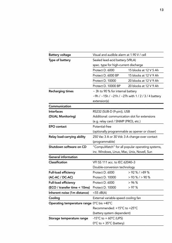
13
Battery voltage Visual and audible alarm at 1.90 V / cell
type of battery sealed lead-acid battery (VrLa)
spec. type for high-current discharge
Protect D. 6000 15 blocks at 12 V 5 ah
Protect D. 6000 BP 15 blocks at 12 V 9 ah
Protect D. 10000 20 blocks at 12 V 9 ah
Protect D. 10000 BP 20 blocks at 12 V 9 ah
Recharging times ~ 3h to 90 % for internal battery
~9h / ~15h / ~21h / ~27h with 1 / 2 / 3 / 4 battery
extension(s)
Communication
Interfaces
(DUAL Monitoring)
rs232 (suB-D (9-pin)), usB
additional: communication slot for extensions
(e.g. relay card / snMP (PrO), etc.)
ePo contact Potential-free
(optionally programmable as opener or closer)
Relay load-carrying ability 250 Vac 3 a or 30 Vdc 3 a change-over contact
(programmable)
shutdown software on CD “compuWatch” for all popular operating systems,
inc. Windows, Linux, Mac, unix, novell, sun
General information
Classification VFi ss 111 acc. to iec 62040–3
Double-conversion technology
Full-load efficiency
(AC-AC / DC-AC)
Protect D. 6000
Protect D. 10000
> 92 % / >89 %
> 93 % / > 90 %
Full-load efficiency
(eCo / transfer time < 10ms)
Protect D. 6000
Protect D. 10000
> 96 %
> 97 %
Inherent noise (1m distance) <55 dB(a)
Cooling external variable-speed cooling fan
operating temperature range 0°c bis +40°c
recommended: +15°c to +25°c
(battery system dependent)
storage temperature range -15°c to + 60°c (uPs)
0°c to + 35°c (battery)
14
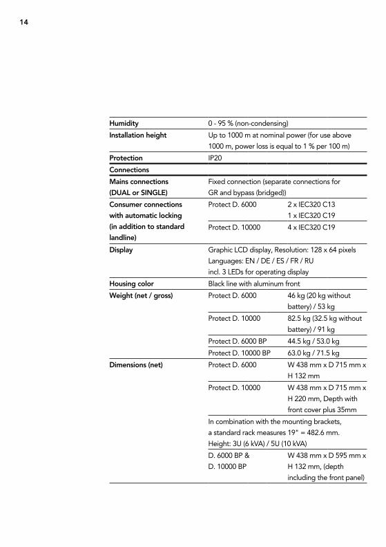
Humidity 0 - 95 % (non-condensing)
Installation height up to 1000 m at nominal power (for use above
1000 m, power loss is equal to 1 % per 100 m)
Protection iP20
Connections
Mains connections
(DUAL or sInGLe)
Fixed connection (separate connections for
gr and bypass (bridged))
Consumer connections
with automatic locking
(in addition to standard
landline)
Protect D. 6000 2 x iec320 c13
1 x iec320 c19
Protect D. 10000 4 x iec320 c19
Display graphic LcD display, resolution: 128 x 64 pixels
Languages: en / De / es / Fr / ru
incl. 3 LeDs for operating display
Housing color Black line with aluminum front
Weight (net / gross) Protect D. 6000 46 kg (20 kg without
battery) / 53 kg
Protect D. 10000 82.5 kg (32.5 kg without
battery) / 91 kg
Protect D. 6000 BP 44.5 kg / 53.0 kg
Protect D. 10000 BP 63.0 kg / 71.5 kg
Dimensions (net) Protect D. 6000 W 438 mm x D 715 mm x
H 132 mm
Protect D. 10000 W 438 mm x D 715 mm x
H 220 mm, Depth with
front cover plus 35mm
in combination with the mounting brackets,
a standard rack measures 19" = 482.6 mm.
Height: 3u (6 kVa) / 5u (10 kVa)
D. 6000 BP &
D. 10000 BP
W 438 mm x D 595 mm x
H 132 mm, (depth
including the front panel)
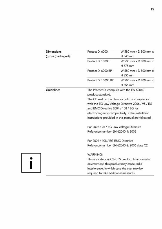
15
Dimensions
(gross (packaged))
Protect D. 6000 W 580 mm x D 800 mm x
H 540 mm
Protect D. 10000 W 580 mm x D 800 mm x
H 675 mm
Protect D. 6000 BP W 580 mm x D 800 mm x
H 355 mm
Protect D. 10000 BP W 580 mm x D 800 mm x
H 355 mm
Guidelines the Protect D. complies with the en 62040
product standard.
the ce seal on the device confirms compliance
with the eg Low Voltage Directive 2006 / 95 / eg
and eMc Directive 2004 / 108 / eg for
electromagnetic compatibility, if the installation
instructions provided in this manual are followed.
For 2006 / 95 / eg Low Voltage Directive
reference number en 62040-1: 2008
For 2004 / 108 / eg eMc Directive
reference number en 62040-2: 2006 class c2
Warning:
this is a category c2–uPs product. in a domestic
environment, this product may cause radio
interference, in which case the user may be
required to take additional measures.
16
3.1 gENEral safEty iNstructiONs
read these operating instructions carefully before using the uPs Protect D. and
its external battery modules (special accessories) for the first time; pay careful
attention to the safety precautions!
use this device for its intended purpose only and in accordance with the safety
instructions and danger warnings in this instruction manual! the device is to be
used only when it is in perfect working condition; correct any problems that may
affect the safety of the device immediately.
the following pictograms appear in this manual:
note: DAnGeR!
in the case of danger to life and limb of the operator.
note: AttentIon!
risk of injury and / or risk of damage to equipment and equipment parts.
note: InFoRMAtIon!
useful and important for the operation of the uPs and the external battery
modules (optional).
3.2 safEty iNstructiONs fOr thE PrOtEct D.
this chapter contains important safety instructions for the uPs Protect D. and
its external battery modules (optional accessories) that must be followed for the
mounting, operation and maintenance of the uninterruptible power supply and
the battery system (internal and external batteries, if applicable).
3. sAFetY ReGULAtIons
17
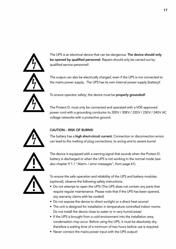
the uPs is an electrical device that can be dangerous. the device should only
be opened by qualified personnel. repairs should only be carried out by
qualified service personnel!
the output can also be electrically charged, even if the uPs is not connected to
the mains power supply. the uPs has its own internal power supply (battery)!
to ensure operator safety, the device must be properly grounded!
the Protect D. must only be connected and operated with a VDe-approved
power cord with a grounding conductor to 200 V / 208 V / 220 V / 230 V / 240 V ac
voltage networks with a protective ground.
CAUtIon – RIsK oF BURns!
the battery has a high short-circuit current. connection or disconnection errors
can lead to the melting of plug connections, to arcing and to severe burns!
the device is equipped with a warning signal that sounds when the Protect D.
battery is discharged or when the uPs is not working in the normal mode (see
also chapter 9.1.1 “alarm- / error messages”, from page 61).
to ensure the safe operation and reliability of the uPs and battery modules
(optional), observe the following safety instructions:
• Do not attempt to open the uPs! (the uPs does not contain any parts that
require regular maintenance. Please note that if the uPs has been opened,
any warranty claims with be voided)
• Do not expose the device to direct sunlight or a direct heat source!
• the unit is designed for installation in temperature controlled indoor rooms.
Do not install the device close to water or in very humid areas!
• if the uPs is brought from a cold environment into the installation area,
condensation may occur. Before using the uPs, it must be absolutely dry;
therefore a waiting time of a minimum of two hours before use is required.
• never connect the mains power input with the uPs output!
18
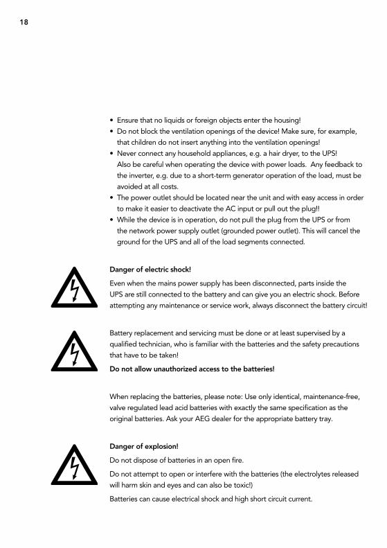
• ensure that no liquids or foreign objects enter the housing!
• Do not block the ventilation openings of the device! Make sure, for example,
that children do not insert anything into the ventilation openings!
• never connect any household appliances, e.g. a hair dryer, to the uPs!
also be careful when operating the device with power loads. any feedback to
the inverter, e.g. due to a short-term generator operation of the load, must be
avoided at all costs.
• the power outlet should be located near the unit and with easy access in order
to make it easier to deactivate the ac input or pull out the plug!!
• While the device is in operation, do not pull the plug from the uPs or from
the network power supply outlet (grounded power outlet). this will cancel the
ground for the uPs and all of the load segments connected.
Danger of electric shock!
even when the mains power supply has been disconnected, parts inside the
uPs are still connected to the battery and can give you an electric shock. Before
attempting any maintenance or service work, always disconnect the battery circuit!
Battery replacement and servicing must be done or at least supervised by a
qualified technician, who is familiar with the batteries and the safety precautions
that have to be taken!
Do not allow unauthorized access to the batteries!
When replacing the batteries, please note: use only identical, maintenance-free,
valve regulated lead acid batteries with exactly the same specification as the
original batteries. ask your aeg dealer for the appropriate battery tray.
Danger of explosion!
Do not dispose of batteries in an open fire.
Do not attempt to open or interfere with the batteries (the electrolytes released
will harm skin and eyes and can also be toxic!)
Batteries can cause electrical shock and high short circuit current.
19
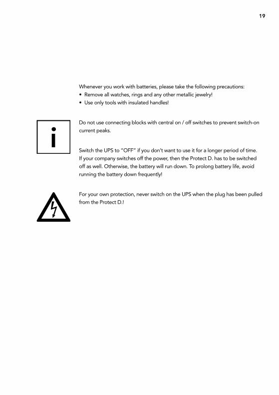
Whenever you work with batteries, please take the following precautions:
• remove all watches, rings and any other metallic jewelry!
• use only tools with insulated handles!
Do not use connecting blocks with central on / off switches to prevent switch-on
current peaks.
switch the uPs to “OFF” if you don’t want to use it for a longer period of time.
if your company switches off the power, then the Protect D. has to be switched
off as well. Otherwise, the battery will run down. to prolong battery life, avoid
running the battery down frequently!
For your own protection, never switch on the uPs when the plug has been pulled
from the Protect D.!
20
3.3 cE cErtificatE
21
4.1 uNPacK aND chEcK
the device has been extensively tested and checked. although packaging and
shipping has been carefully carried out, damage in transit cannot be totally ruled
out.
any transport damage claims must be made directly to the shipping company!
upon receipt, check the contents of the transport containers for any damage. if
necessary, ask the shipping company to check the goods and make a note of any
damages while an employee of the shipping company is still present and report
the damage within eight days of receipt to an aeg representative or retailer.
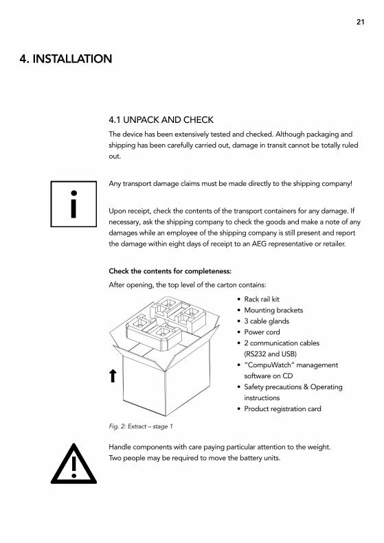
Check the contents for completeness:
after opening, the top level of the carton contains:
4. InstALLAtIon
Fig. 2: Extract – stage 1
• rack rail kit
• Mounting brackets
• 3 cable glands
• Power cord
• 2 communication cables
(rs232 and usB)
• “compuWatch” management
software on cD
• safety precautions & Operating
instructions
• Product registration card
Handle components with care paying particular attention to the weight.
two people may be required to move the battery units.
22
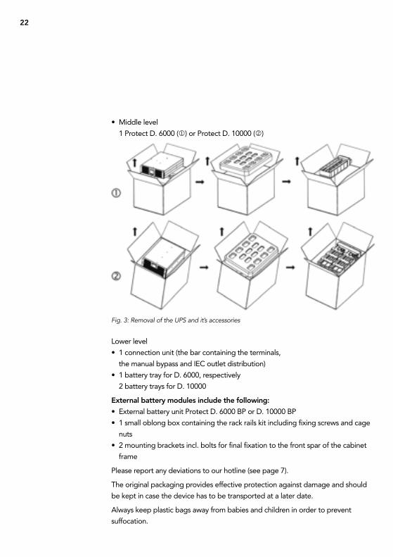
• Middle level
1 Protect D. 6000 () or Protect D. 10000 ()
Lower level
• 1 connection unit (the bar containing the terminals,
the manual bypass and iec outlet distribution)
• 1 battery tray for D. 6000, respectively
2 battery trays for D. 10000
external battery modules include the following:
• external battery unit Protect D. 6000 BP or D. 10000 BP
• 1 small oblong box containing the rack rails kit including fixing screws and cage
nuts
• 2 mounting brackets incl. bolts for final fixation to the front spar of the cabinet
frame
Please report any deviations to our hotline (see page 7).
the original packaging provides effective protection against damage and should
be kept in case the device has to be transported at a later date.
always keep plastic bags away from babies and children in order to prevent
suffocation.
Fig. 3: Removal of the UPS and it’s accessories
23
4.2 iNstallatiON
the Protect D. is designed to be installed in a protected environment. When
choosing the location, make sure that there is adequate ventilation and any other
environmental requirements deemed appropriate.
the Protect D. is air-cooled. Do not block vents or openings!
the uPs and its battery modules in particular, should preferably be operated at
room temperature (between 15°c and 25°c).
install the devices in a room that is dry, relatively dust-free and free of chemical
vapors.
Make sure that no magnetic storage media are stored and / or operated in the
vicinity of the Protect D.
check the type rating plate to make sure that the voltage and frequency
specifications match those of your load segments.
4.3 assEmbly
For rack installation of the uPs system and its external battery units (Optional
accessories), please note the following:
• to prevent damage from vibration and shocks, the installation location has
to have adequate stability.
• Make sure that racks are able to support the installation.
• Place any external battery units directly underneath the uPs system.
to ensure maximum mechanical stability, place each tray in its own rack mount.
• Due to their heavy weight, install the units in the lower part of the cabinet.
• install the units allowing for adequate air circulation.
• external battery packs are to be placed directly below the uPs system.
to maintain maximum mechanical stability, mount each tray on a pair of
separate rack rails.
• avoid extremes of temperature! in order to maximize battery life, an
environmental temperature of 15°c to 25°c is recommended. Do not expose
the units to direct sunlight or operate them close to any other heat sources,
e.g. radiators.
24
• Protect the units from external environmental influences (particularly moisture
and dust). Please pay special attention to the information in chapter 3, starting
on page 16 of this manual.
• if the device is taken from a cold room and brought into a warm room or if the
room temperature suddenly drops, condensation may occur within the device.
to prevent any condensation buildup, let the device acclimatize for 2 hours
before you switch it on.
Installation in a 19" rack
Mount the trays in the lower third of the rack, taking into account the center
of gravity of the rack and making sure that there is adequate fresh air supply.
universal mounting rail systems are included. the amount of space required for
the 6 kVa uPs is 3u and 5u for the 10 kVa. external battery extension units each
require, directly under the uPs, a further 3u.
1. Firstly install the depth variable enclosed rack rails. tighten the mounting screws
on the left and right rails, leaving the rail loosely fastened. roughly adjust the
depth of the rail in the installation location in the rack.
2. Locate the rack mounting positions appropriately and use each two cage nuts
on each spar corresponding to the position of the rack rails. each rack rail
requires 4 cage nuts. ensure that there is sufficient space below each uPs for
further addition of battery extension units allowing for a height of 3u. now
insert the rack rails and attach them to the front and rear of each spar with
two screws. securely tighten all screws. Please do not forget about the screws
inserted in step 1.
3. carefully lift the uPs unit and place it on a secure flat surface.
4. now fasten the two brackets that come with the device to the side of the uPs
and, if using, an external battery unit according to Fig. 4. Make sure to put the
bracket marked “L” on the left and the one marked “r” on the right hand side.
next, above the rack rails fastening on the cabinet front posts attach a further
cage nut for final mounting of the uPs unit on the mounting brackets.
25
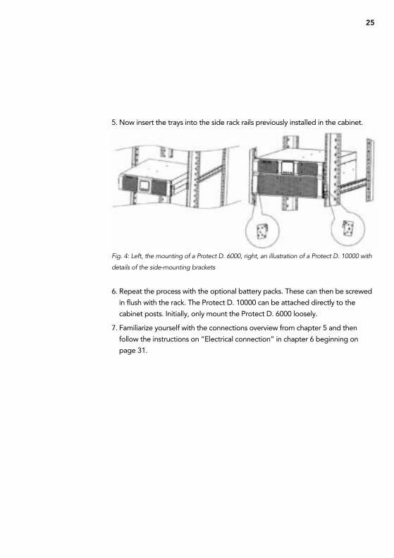
5. now insert the trays into the side rack rails previously installed in the cabinet.
6. repeat the process with the optional battery packs. these can then be screwed
in flush with the rack. the Protect D. 10000 can be attached directly to the
cabinet posts. initially, only mount the Protect D. 6000 loosely.
7. Familiarize yourself with the connections overview from chapter 5 and then
follow the instructions on “electrical connection” in chapter 6 beginning on
page 31.
Fig. 4: Left, the mounting of a Protect D. 6000, right, an illustration of a Protect D. 10000 with
details of the side-mounting brackets
26
A B C
DEF E F
DEF E F
A B C
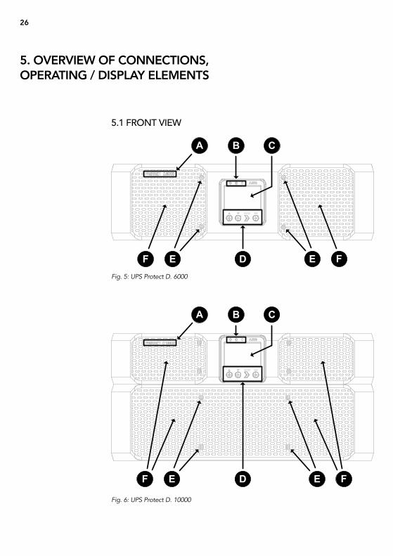
5. oVeRVIeW oF ConneCtIons, oPeRAtInG / DIsPLAY eLeMents
5.1 frONt viEW
Fig. 6: UPS Protect D. 10000
Fig. 5: UPS Protect D. 6000
27
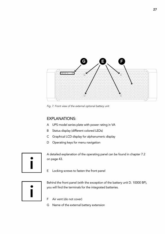
G E F
Fig. 7: Front view of the external optional battery unit
EXPlaNatiONs:
a uPs model series plate with power rating in Va
B status display (different colored LeDs)
c graphical LcD display for alphanumeric display
D Operating keys for menu navigation
a detailed explanation of the operating panel can be found in chapter 7.2
on page 43.
e Locking screws to fasten the front panel
Behind the front panel (with the exception of the battery unit D. 10000 BP),
you will find the terminals for the integrated batteries.
F air vent (do not cover)
g name of the external battery extension
28
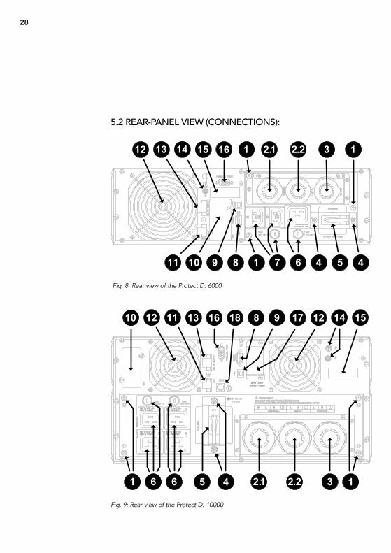
161210 81311 17 1218
36 51 4 2 1. 2 2. 16
9 14 15
161312 2 11514 . 2 2. 31 1
4 56 41 7810 911
5.2 rEar-PaNEl viEW (cONNEctiONs):
Fig. 8: Rear view of the Protect D. 6000
Fig. 9: Rear view of the Protect D. 10000

29
EXPlaNatiONs:
1 Locking screws for the removable connection unit
2 Power input – separate connection of bypass (2.1) and rectifier unit (2.2)
is possible (dual input)
the feed can be run either from the rear-side or from the top of the cable glands
(illustration shows rear-side). if only one cable is to be laid, the portable bypass
feed (1.2) remains unused.
3 uPs output (load) over fixed connection
4 Locking screws for securing the bracket built into the manual bypass switch
connection unit
5 Manual bypass switch
6 consumer connection via iec60320 c19 sockets, automatic arrestor fitted
with an upstream fuse
7 consumer connection via iec60320 c13 sockets, automatic arrestor fitted
with an upstream fuse
taken from the consumer line by pressing the respective push button output of
each iec socket.
8 rs232 communication interface (sub-D9 jack)
9 usB communication interface
10 communication slot for optional extension cards:
relay card, card for remote on / off, snMP, …
the usB and the rs232 communication interfaces cancel each other out, i.e.
either usB or rs232. the communication slot is dual-monitor enabled, i.e. can
be used parallel to the usB or rs232 interface.
30
11 emergency power off contact, can be configured as open or closed
12 Fans (caution: maintain a minimum of 100mm free space around the fans for
free movement of air)
13 changeover contact, potential free, programmable via the uPs control panel
14 Housing earth potential connection via additional screw(s)
15 sticker with barcodes for article (gLn) and serial number (s/n) identification
16 connector for parallel operation (separate Bus line required – see chapter 10)
17 Keyed connector unit for optional external battery pack (accessible by
removing the cover)
18 Line detection connector (included with optional external battery pack)
the connection of the external optional battery pack(s) on Protect D. 6000 is
made from scratch – see chapter 6.4.2.
31
WarNiNg
Before beginning work, please ensure that cables are disconnected and that
power is turned off.
in order to simplify assembly and to avoid deformation of the connector unit,
secure in and output cables only with separate connection units. use only highly
flexible fine-stranded cables. connect the connector firstly to the uPs.
High touch voltages can occur with freely accessible metal parts. Protective
measures against earthing can be made through the grounding of the Protect D.
via the designated (n) grounding screw(s) ( / Pe). Prior to commissioning, please
ensure that Protect D. and it optional battery tray contents are compliant with
regulations, e.g. VDe0100 is earthed. to do this, connect the terminals “ / Pe”
(earth) to the grounding point of the cabinet frame.
Before beginning connection work, ensure that:
• the values of the mains voltage (supply) and frequency match those on the label
of the uPs,
• the ground connection prescribed by iec standards or regulations is consistent
with local standards and regulations,
• the uPs is connected to the mains supply via a separate connection with the
cable secured for low voltage distribution,
• Fuses or circuit breakers are used to match the values specified in chapter 6.2
• the connecting line from the fuse to the uPs with a minimum cross section
according to chapter 6.2 “connection cross section and fuses”
6. eLeCtRICAL ConneCtIon
32
6.1 safEty Of PErsONNEl
When fitting the connecting cables, please not the following:
• switch off power
• secure against being switched on again
• Verify that equipment is isolated
• earth and short circuit
• cover or fence off nearby live parts
the uPs may retain residual voltage, which can be dangerous. the device may
only be installed by qualified personnel and, if opened, repairs may on be carried
out by qualified service personnel!
6.2 cONNEctiON crOss-sEctiON aND fusEs
refer to the required dimensions of the table below (based on Din en 60439-1
(VDe 0660 part 500) and take into account the built-in terminal block):
Protect D. 6000 Protect D. 10000
Power supply line 1 min.
(UPs input max.
rectifier and possible bypass)
4 mm²
10 mm
6 mm²
10 mm²
Power supply line 2 min.
(optional) max.
(Bypass-input)
4 mm²
10 mm²
6 mm²
10 mm²
Consumer connection min.
(UPs permanent max.
connection)
4 mm²
10 mm²
6 mm²
10 mm²
Battery connection (front)
using preassembled,
polarity battery
connectors.
(rear)
using preassembled,
polarity battery
connectors.
Fuse (UPs Input)
(specifications are valid for both
mains 1 and mains 2 if necessary )
32 a 50 a
Observed with the use of circuit breakers
tripping characteristics “c“ note!
Consumer protection
(recommended max.)
6 a 10 a
tripping characteristic “B“ note!
33
the recommended maximum consumer protection ensures the selectivity of
each uPs output circuit. Failure to comply with this recommendation may cause
interruption to other loads connected to this uPs.
Protect D. offers high availability and the possibility of a separate supply from the
rectifier and bypass (dual-input) all connected from one single power supply. if you
require connection from two power supplies, they must be from the same network
with identical reference potential. For other network connections, please contact
aeg Power solutions.
Fig.10: Supply with separate leads (DUAL-INPUT)
Fig.11: Central supply with one lead (SINGLE-INPUT)
Fig.12: Operating as frequency converter (Bypass deactivated)
34
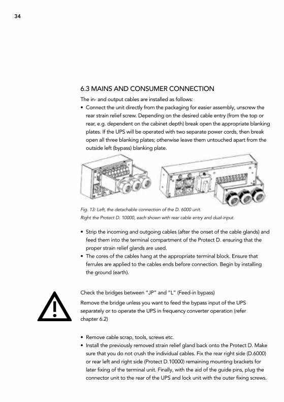
6.3 maiNs aND cONsumEr cONNEctiON
the in- and output cables are installed as follows:
• connect the unit directly from the packaging for easier assembly, unscrew the
rear strain relief screw. Depending on the desired cable entry (from the top or
rear, e.g. dependent on the cabinet depth) break open the appropriate blanking
plates. if the uPs will be operated with two separate power cords, then break
open all three blanking plates; otherwise leave them untouched apart from the
outside left (bypass) blanking plate.
• strip the incoming and outgoing cables (after the onset of the cable glands) and
feed them into the terminal compartment of the Protect D. ensuring that the
proper strain relief glands are used.
• the cores of the cables hang at the appropriate terminal block. ensure that
ferrules are applied to the cables ends before connection. Begin by installing
the ground (earth).
check the bridges between “JP” and “L” (Feed-in bypass)
remove the bridge unless you want to feed the bypass input of the uPs
separately or to operate the uPs in frequency converter operation (refer
chapter 6.2)
• remove cable scrap, tools, screws etc.
• install the previously removed strain relief gland back onto the Protect D. Make
sure that you do not crush the individual cables. Fix the rear right side (D.6000)
or rear left and right side (Protect D.10000) remaining mounting brackets for
later fixing of the terminal unit. Finally, with the aid of the guide pins, plug the
connector unit to the rear of the uPs and lock unit with the outer fixing screws.
Fig. 13: Left, the detachable connection of the D. 6000 unit.
Right the Protect D. 10000, each shown with rear cable entry and dual-input.
35
in the case of a joint distribution box. (circuits with both network as well as uPs
power), you must identify each respective circuit power supply (ac or uPs).
the load of the uPs should not exceed the specified maximum capacity of the
device at any time. if there is a device overload the red LeD light will flag a fault
accompanied by an audible warning signal. Depending on the magnitude of the
overload, the supply to the connected consumers remains for an amount of time.
However, the connected load must be reduced immediately.
Failure to action the state “device overload” can lead to a total loss of all uPs
functions!
Do not connect household appliances or machine tools to the uPs.
Do not connect additional loads to the uPs or switch if there is a power failure.
i.e. the uPs is in standby mode!
as a rule, when in normal operation and no overload has occurred, then no
overload should occur in battery usage.
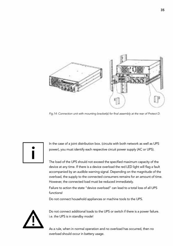
Fig.14: Connection unit with mounting bracket(s) for final assembly at the rear of Protect D.
36
a flashing LeD in conjunction with a fault signal indicates a disconnection fault.
Follow the instructions in chapter 9.1
Finally check the seating of the emergency shutdown connector and the cable
bridge. check that the two outer screws of the plug are firmly seated (refer to
page 30 item 11)
if you would like to use the emergency function, refer to chapter 8.4 on page 58.
the built-in emergency shutdown of the uPs is only for power. this is carried out
electronically and does not constitute an eMergencY stOP device according to
Din en isO 13850.
6.4 cONtactiNg thE battEry mODulEs
this chapter refers to the contact of the internal battery and then to a slide-on
connection of the optional external battery pack(s)
6.4.1 cONNEctiNg thE iNtErNal battEry• remove the four screws on the front panel with a suitable screwdriver (Phillips
PH1 recommended item “e” of the illustration on page 26)
• Hold the Protect D. 6000 on the left and right sides behind the front panel and
carefully pull the uPs out about 70mm from the front of the rack frame (not
required with Protect D. 10000)
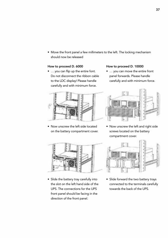
37
How to proceed D. 6000
• … you can flip up the entire font.
Do not disconnect the ribbon cable
to the LDc display! Please handle
carefully and with minimum force.
• now unscrew the left side located
on the battery compartment cover.
• slide the battery tray carefully into
the slot on the left hand side of the
uPs. the connections for the uPs
front panel should be facing in the
direction of the front panel.
How to proceed D. 10000
• … you can move the entire front
panel forwards. Please handle
carefully and with minimum force.
• now unscrew the left and right side
screws located on the battery
compartment cover.
• slide forward the two battery trays
connected to the terminals carefully
towards the back of the uPs.
• Move the front panel a few millimeters to the left. the locking mechanism
should now be released
38
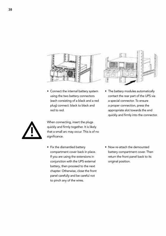
• connect the internal battery system
using the two battery connectors
(each consisting of a black and a red
plug) connect: black to black and
red to red.
When connecting, insert the plugs
quickly and firmly together. it is likely
that a small arc may occur. this is of no
significance.
• Fix the dismantled battery
compartment cover back in place.
if you are using the extensions in
conjunction with the uPs external
battery, then proceed to the next
chapter. Otherwise, close the front
panel carefully and be careful not
to pinch any of the wires.
• the battery modules automatically
contact the rear part of the uPs via
a special connector. to ensure
a proper connection, press the
appropriate slot towards the end
quickly and firmly into the connector.
• now re-attach the demounted
battery compartment cover. then
return the front panel back to its
original position.
39
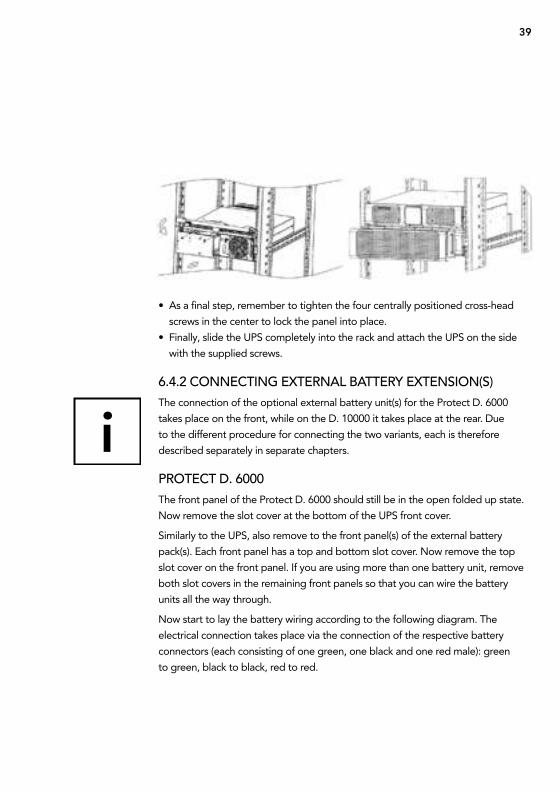
• as a final step, remember to tighten the four centrally positioned cross-head
screws in the center to lock the panel into place.
• Finally, slide the uPs completely into the rack and attach the uPs on the side
with the supplied screws.
6.4.2 cONNEctiNg EXtErNal battEry EXtENsiON(s)
the connection of the optional external battery unit(s) for the Protect D. 6000
takes place on the front, while on the D. 10000 it takes place at the rear. Due
to the different procedure for connecting the two variants, each is therefore
described separately in separate chapters.
PrOtEct D. 6000
the front panel of the Protect D. 6000 should still be in the open folded up state.
now remove the slot cover at the bottom of the uPs front cover.
similarly to the uPs, also remove to the front panel(s) of the external battery
pack(s). each front panel has a top and bottom slot cover. now remove the top
slot cover on the front panel. if you are using more than one battery unit, remove
both slot covers in the remaining front panels so that you can wire the battery
units all the way through.
now start to lay the battery wiring according to the following diagram. the
electrical connection takes place via the connection of the respective battery
connectors (each consisting of one green, one black and one red male): green
to green, black to black, red to red.
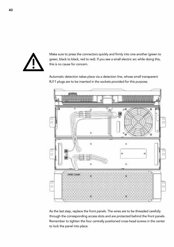
40
Make sure to press the connectors quickly and firmly into one another (green to
green, black to black, red to red). if you see a small electric arc while doing this,
this is no cause for concern.
automatic detection takes place via a detection line, whose small transparent
rJ11 plugs are to be inserted in the sockets provided for this purpose.
as the last step, replace the front panels. the wires are to be threaded carefully
through the corresponding access slots and are protected behind the front panels.
remember to tighten the four centrally positioned cross-head screws in the center
to lock the panel into place.
41
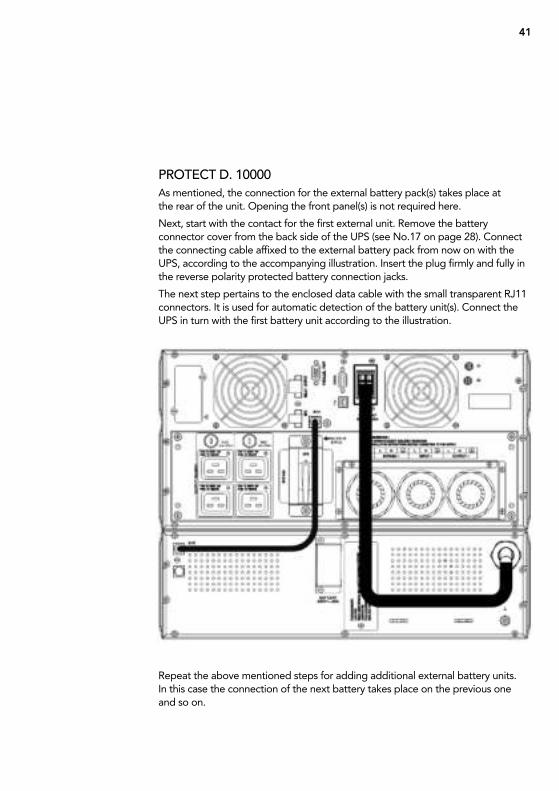
PrOtEct D. 10000
as mentioned, the connection for the external battery pack(s) takes place at the rear of the unit. Opening the front panel(s) is not required here.
next, start with the contact for the first external unit. remove the battery connector cover from the back side of the uPs (see no.17 on page 28). connect the connecting cable affixed to the external battery pack from now on with the uPs, according to the accompanying illustration. insert the plug firmly and fully in the reverse polarity protected battery connection jacks.
the next step pertains to the enclosed data cable with the small transparent rJ11 connectors. it is used for automatic detection of the battery unit(s). connect the uPs in turn with the first battery unit according to the illustration.
repeat the above mentioned steps for adding additional external battery units. in this case the connection of the next battery takes place on the previous one and so on.
42
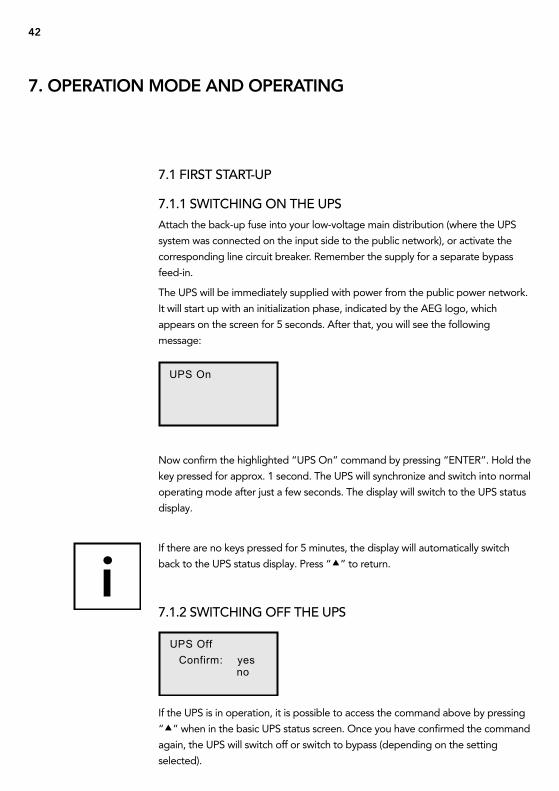
UPS On
UPS Off
Confirm: yes no
7.1 first start-uP
7.1.1 sWitchiNg ON thE uPs
attach the back-up fuse into your low-voltage main distribution (where the uPs
system was connected on the input side to the public network), or activate the
corresponding line circuit breaker. remember the supply for a separate bypass
feed-in.
the uPs will be immediately supplied with power from the public power network.
it will start up with an initialization phase, indicated by the aeg logo, which
appears on the screen for 5 seconds. after that, you will see the following
message:
now confirm the highlighted “uPs On” command by pressing “enter”. Hold the
key pressed for approx. 1 second. the uPs will synchronize and switch into normal
operating mode after just a few seconds. the display will switch to the uPs status
display.
if there are no keys pressed for 5 minutes, the display will automatically switch
back to the uPs status display. Press “” to return.
7.1.2 sWitchiNg Off thE uPs
if the uPs is in operation, it is possible to access the command above by pressing
“” when in the basic uPs status screen. Once you have confirmed the command
again, the uPs will switch off or switch to bypass (depending on the setting
selected).
7. oPeRAtIon MoDe AnD oPeRAtInG
43
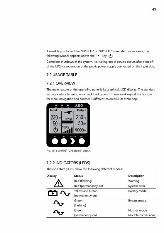
Input Output
to enable you to find the “uPs On” or “uPs Off” menu item more easily, the
following symbol appears above the “” key:
complete shutdown of the system, i.e., taking out of service occurs after shut-off
of the uPs via separation of the public power supply connected on the input side.
7.2 usagE tablE
7.2.1 OvErviEW
the main feature of the operating panel is its graphical, LcD display. the standard
setting is white lettering on a black background. there are 4 keys at the bottom
for menu navigation and another 3 different-colored LeDs at the top.
7.2.2 iNDicatOrs (lEDs)
the indicators (LeDs) show the following different modes:
Fig. 15: Standard “UPS status” display
Display status Description
red (flashing) Warning
red (permanently on) system error
Yellow and green
(permanently on)
Battery mode
green
(flashing)
Bypass mode
green
(permanently on)
normal mode
(double-conversion)
44
7.2.3 OPEratiNg KEys (NavigatiON)
the 4 keys for navigation control the following functions:
“” key: Press this key to scroll upwards in the menu levels or to alter
a value you want to set.
if you press this key in the status display, you will access the
“uPs On or Off” menu item.
“” key: Press this key to scroll downwards in the menu levels or to
alter a value you want to set.
“enter” key: Press this key briefly to select the corresponding menu item.
to confirm and store a menu item in the “settings” menu,
press this key and hold it down for at least 1 second.
„ esc ” taste: Press this key to return to the previous menu level without
altering any settings. if you press this key in the status display,
you will access the main menu.
if no keys are pressed, the display will automatically return to the standard display
after 5 minutes. if you want to “freeze” a screen in the “Measurements” menu,
press “” and “” at the same time for about 3 seconds. a small key appears on
the upper right-hand side of the display to indicate this setting. Press both these
keys again for approx. 3 seconds to cancel this setting.
45
Event log
UPS Status
Measurements
Control
Ident i f icat ion
Menu
Sett ings
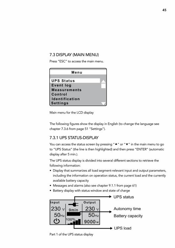
7.3 DisPlay (maiN mENu)
Press “esc” to access the main menu.
Main menu for the LcD display
the following figures show the display in english (to change the language see
chapter 7.3.6 from page 51 “settings”).
7.3.1 uPs status-DisPlay
You can access the status screen by pressing “” or “” in the main menu to go
to “uPs status” (the line is then highlighted) and then press “enter” (automatic
display after 5 min.).
the uPs status display is divided into several different sections to retrieve the
following information:
• Display that summarizes all load segment-relevant input and output parameters,
including the information on operation status, the current load and the currently
available battery capacity
• Messages and alarms (also see chapter 9.1.1 from page 61)
• Battery display with status window and state of charge
Part 1 of the uPs status display
46
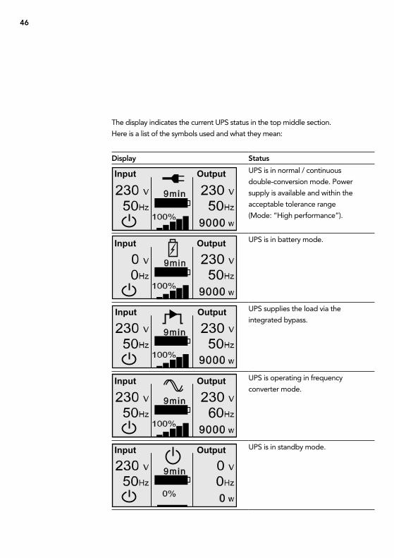
Display status
uPs is in normal / continuous
double-conversion mode. Power
supply is available and within the
acceptable tolerance range
(Mode: “High performance”).
uPs is in battery mode.
uPs supplies the load via the
integrated bypass.
uPs is operating in frequency
converter mode.
uPs is in standby mode.
the display indicates the current uPs status in the top middle section.
Here is a list of the symbols used and what they mean:
47
uPs is operating in economical mode
(ecO mode).
uPs is testing the battery.
Display for 10 seconds after a
successful battery test.
uPs reports a defective or
disconnected battery system.
uPs is overloaded.
48
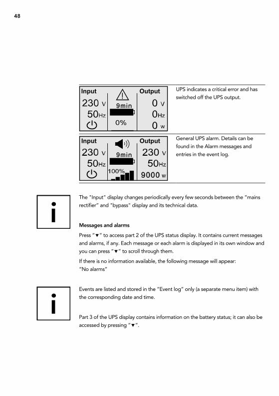
Input Output
Input Output uPs indicates a critical error and has
switched off the uPs output.
general uPs alarm. Details can be
found in the alarm messages and
entries in the event log.
the "input" display changes periodically every few seconds between the “mains
rectifier” and "bypass" display and its technical data.
Messages and alarms
Press “” to access part 2 of the uPs status display. it contains current messages
and alarms, if any. each message or each alarm is displayed in its own window and
you can press “” to scroll through them.
if there is no information available, the following message will appear:
“no alarms”
events are listed and stored in the “event log” only (a separate menu item) with
the corresponding date and time.
Part 3 of the uPs display contains information on the battery status; it can also be
accessed by pressing “”.
49
Battery status display Description
Battery charge Batteries are currently charging with constant
current.
Battery float charge Batteries are currently being supplied with constant
voltage.
Battery resting Batteries on standby, but in “sleep” mode
(part of the battery standby cycle mode).
Battery discharge Batteries are currently discharging, e.g. due
to a power outage.
Battery disconnected Battery system not available because currently not
connected.
7.3.2 EvENt lOg
up to 127 events are stored in the internal non-volatile event memory in the uPs.
the last event that occurred is the first on the list, followed by other previous
events. similar to the messages and alarms, each event is shown in its own
window.
an event is indicated along with the date and time, followed by a description in
plain text. the numerical code facilitates error analysis and other procedures in
dealing with the event that has occurred (also see chapter 9.1.1 from page 61). in
the lower right-hand corner of the display, you will find the total number of events
already stored as well as your position when scrolling through the window. “1 / …”
indicates the most recent, last stored event (= starting position when accessed).
if there are no events stored or if the event memory has been deleted (also see
chapter 7.3.6 from page 51), the following message will appear: “no events in the
event log”.
accEssiNg thE EvENt lOg
access the event log by pressing “esc” to go to the main menu and then
pressing “” or “” to go to the “event log” menu item (line appears
highlighted) and then press “enter” (basis / starting point is the uPs status
display).
return to the uPs status display by pressing “esc” again (or automatically
after 5 minutes if no other keys are pressed).
50
7.3.3 mEasurEmENts
select this menu item to find the following measurements in this order:
if you want to see any particular measurement on the screen permanently, you
can “freeze” the screen in the Measurements menu. to do so, press “” and
“” for approx. 3 seconds at the same time until a small key appears in the upper
right-hand corner of the display. Press the two buttons again at the same time for
approx. 3 seconds to cancel this setting.
7.3.4 cONtrOl
During normal mode, you can active this menu item to access the following
sub-menu items: “go to bypass mode”, “Battery test”, and “reset error state”.
Depending on the operating mode, only those sub-menu items that are available
will appear.
Power Usage efficiency [%]
output power (active and apparent power) [W] & [Va]
output power (current and power factor) [a]
output (voltage and frequency) [V] & [Hz]
Input (voltage and frequency) [V] & [Hz]
Battery (voltage and charge state) [V] & [%]
DC bus (intermediate circuit voltage) [V]
external battery modules
total kWh consumption [kWh]
51
7.3.5 iDENtificatiON
activate this menu item to view the following sub-menu items: “type / Model”,
“Part number”, “serial number” and finally the current “uPs firmware” version
one after the other.
7.3.6 sEttiNgs
the following table provides you with a detailed description of the possible user
settings using the uPs operating panel:
”Control” / Command Description
Go to Bypass / normal Possibility to change operation mode.
Menu item visible only when the uPs is currently
in Bypass or normal Mode.
Battery test conducts battery test after confirmation.
cancellation possible at any time as needed.
Reset error state resets alarm messages
Manually clears any active alarms, such as battery fault
detected or Dc Bus over / under voltage.
With an active battery fault alarm, the battery test status
will also simultaneously reset to “not tested”.
Description Adjustable parameters Presetting
Change Language [english], [german], [French], [spanish],
[russian]
nOte: Language selection order depends
on the current selection.
english
User Password [[enabled<aaaa>], [disabled]
if enabled, select character between a~z
and numbers between 0~9.
nOte: if you enter an incorrect password, the
message “incorrect Password” appears. Press
any button to return to the password screen
and retry the password.
disabled
52
Description Adjustable parameters Presetting
Audible Alarms [enabled], [disabled]
nOte. the setting takes place immediately
and will remain permanently stored, even in
the case of power failures.
this differs from the mute feature where the
horn is temporarily silenced on any button
press, but turns on again if a new alarm is
triggered.
enabled
set Date and time set Month, Day, Year, Hours and Minutes;
Date layout: mm / dd / yyyy
time layout: hh:mm
nOte: the date format depends on the
language selection.
nOte: time is a 24-hour clock.
03 / 15 / 2010
18:00
Relay configuration [uPs ok], [on bypass],
[on economical mode (ecO)],
[on battery], [battery low],
[battery fault], [battery missing],
[fan fault], [combined alarm]
uPs ok
Control Commands
from serial Port
[enabled], [disabled]
if enabled, control commands are
accepted through serial & usB port
and cards in the communication slot.
if Disabled, configuration and load control
commands are restricted to LcD panel only.
enabled
output Voltage [200V], [208V], [220V], [230V], [240V],
[auto-sensing]
setting only available in uPs stand-by mode.
auto-sensing
output Frequency [50Hz], [60Hz], [auto-sensing]
setting only available in uPs stand-by mode.
auto-sensing
53
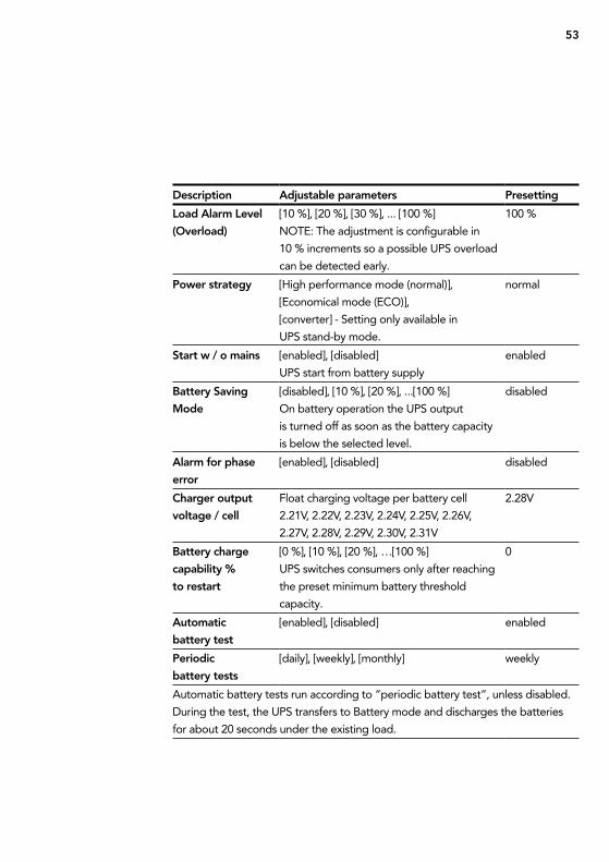
Description Adjustable parameters Presetting
Load Alarm Level
(overload)
[10 %], [20 %], [30 %], ... [100 %]
nOte: the adjustment is configurable in
10 % increments so a possible uPs overload
can be detected early.
100 %
Power strategy [High performance mode (normal)],
[economical mode (ecO)],
[converter] - setting only available in
uPs stand-by mode.
normal
start w / o mains [enabled], [disabled]
uPs start from battery supply
enabled
Battery saving
Mode
[disabled], [10 %], [20 %], ...[100 %]
On battery operation the uPs output
is turned off as soon as the battery capacity
is below the selected level.
disabled
Alarm for phase
error
[enabled], [disabled] disabled
Charger output
voltage / cell
Float charging voltage per battery cell
2.21V, 2.22V, 2.23V, 2.24V, 2.25V, 2.26V,
2.27V, 2.28V, 2.29V, 2.30V, 2.31V
2.28V
Battery charge
capability %
to restart
[0 %], [10 %], [20 %], …[100 %]
uPs switches consumers only after reaching
the preset minimum battery threshold
capacity.
0
Automatic
battery test
[enabled], [disabled] enabled
Periodic
battery tests
[daily], [weekly], [monthly] weekly
automatic battery tests run according to “periodic battery test”, unless disabled.
During the test, the uPs transfers to Battery mode and discharges the batteries
for about 20 seconds under the existing load.
54
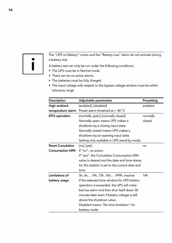
the “uPs on Battery” notice and the “Battery Low” alarm do not activate during
a battery test.
a battery test can only be run under the following conditions:
• the uPs must be in normal mode
• there can be no active alarms
• the batteries must be fully charged.
• the input voltage with respect to the bypass voltage window must be within
tolerance range
Description Adjustable parameters Presetting
High ambient
temperature alarm
[enabled], [disabled]
Preset alarm threshold at > 40 °c
enabled
ePo operation [normally open], [normally closed]
normally open means uPs makes a
shutdown by a closing input state.
normally closed means uPs makes a
shutdown by an opening input state.
setting only available in uPs stand-by mode.
normally
closed
Reset Cumulative
Consumption kWh
[no], [yes]
if “no”, no action.
if “yes”, the cumulative consumption kWh
value is cleared and the date and time stamp
for this statistic is set to the current date and
time.
no
Limitations of
battery usage
5h, 6h, ...14h, 15h, 16h, …999h, inactive
if the selected time window for uPs battery
operation is exceeded, the uPs will make
bat low alarm and then shut itself down 30
minutes later even if battery voltage is still
above the shutdown value.
Disabled means “no time limitation” for
battery mode
14h
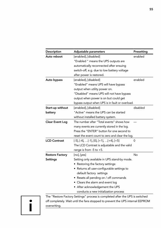
55
Description Adjustable parameters Presetting
Auto reboot [enabled], [disabled]
"enabled " means the uPs outputs are
automatically reconnected after ensuing
switch-off, e.g. due to low battery voltage
after power is restored.
enabled
Auto bypass [enabled], [disabled]
“enabled” means uPs will have bypass
output when utility power on.
“Disabled” means uPs will not have bypass
output when power is on but could get
bypass output when uPs is in fault or overload.
enabled
start-up without
battery
[enabled], [disabled]
"active" means the uPs can be started
without installed battery system.
disabled
Clear event Log the number after “total events” shows how
many events are currently stored in the log.
Press the “enter” button for one second to
reset the event count to zero and clear the log.
—
LCD Contrast [-5], [-4], …[-1], [0], [+1], …[+4], [+5]
the LcD contrast is adjustable and the valid
range is from -5 to +5.
0
Restore Factory
settings
[no], [yes]
setting only available in uPs stand-by mode.
• restoring the factory settings:
• returns all user-configurable settings to
default factory settings
• resets all pending on / off commands
• clears the alarm and event log
• after acknowledgement the uPs
conducts a new initialization process
no
the “restore Factory settings” process is completed after the uPs is switched
off completely. Wait until the fans stopped to prevent the uPs internal eePrOM
overwriting.
56
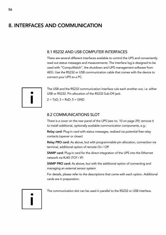
8.1 rs232 aND usb cOmPutEr iNtErfacEs
there are several different interfaces available to control the uPs and conveniently
read out status messages and measurements. the interface log is designed to be
used with “compuWatch”, the shutdown and uPs management software from
aeg. use the rs232 or usB communication cable that comes with the device to
connect your uPs to a Pc.
the usB and the rs232 communication interface rule each another out, i.e. either
usB or rs232. Pin allocation of the rs232 sub-D9 jack:
2 = txD; 3 = rxD; 5 = gnD
8.2 cOmmuNicatiONs slOt
there is a cover on the rear panel of the uPs (see no. 10 on page 29); remove it
to install additional, optionally available communication components, e.g.:
Relay card: Plug-in card with status messages, realized via potential-free relay
contacts (opener or closer)
Relay PRo card: as above, but with programmable pin allocation, connection via
terminal, additional option of remote On / Off
snMP card: Plug-in card for the direct integration of the uPs into the ethernet
network via rJ45 (tcP / iP)
snMP PRo card: as above, but with the additional option of connecting and
managing an external sensor system
For details, please refer to the descriptions that come with each option. additional
cards are in preparation.
the communication slot can be used in parallel to the rs232 or usB interface.
8. InteRFACes AnD CoMMUnICAtIon
57
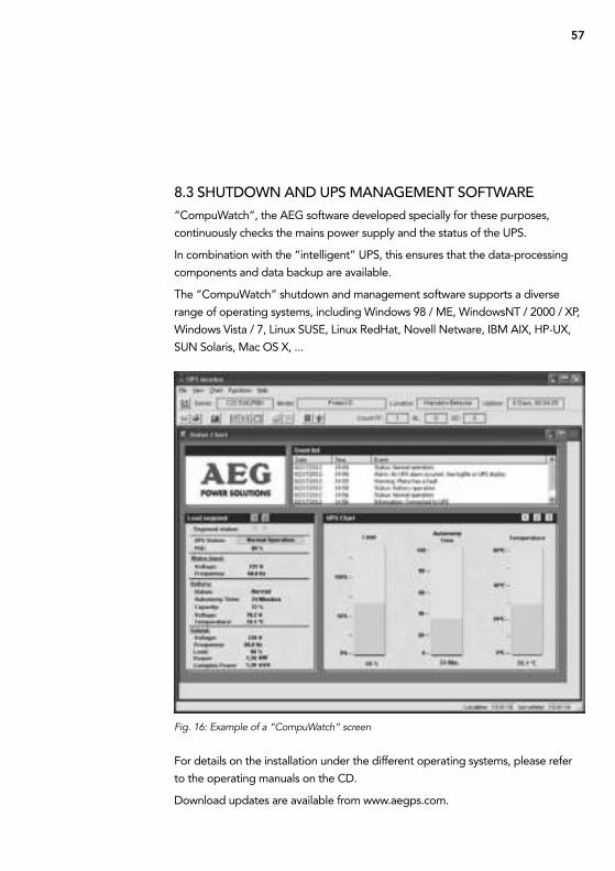
8.3 shutDOWN aND uPs maNagEmENt sOftWarE
“compuWatch”, the aeg software developed specially for these purposes,
continuously checks the mains power supply and the status of the uPs.
in combination with the “intelligent” uPs, this ensures that the data-processing
components and data backup are available.
the “compuWatch” shutdown and management software supports a diverse
range of operating systems, including Windows 98 / Me, Windowsnt / 2000 / XP,
Windows Vista / 7, Linux suse, Linux redHat, novell netware, iBM aiX, HP-uX,
sun solaris, Mac Os X, ...
Fig. 16: Example of a “CompuWatch“ screen
For details on the installation under the different operating systems, please refer
to the operating manuals on the cD.
Download updates are available from www.aegps.com.
58
8.4 EPO (emErgENcy POWEr off)
all the devices in the Protect D. series are equipped with a connection that allows
the immediate shutdown of the uPs output to deactivate any connected devices
and does not follow the control software shutdown process.
note:
Once the emergency power off has been activated, the uPs outputs are
voltage-free. the uPs will not return to normal operation until the emergency
power off has been confirmed / reset and a manual reboot is performed by
activating “uPs On” switch once again.
to install the emergency Power Off, proceed as follows:
1. check to see that the uPs is switched off and switch it off if necessary.
2. remove the plug from the ePO insert on the rear panel of the uPs by
unscrewing the 2 outer screws (also see page 30 item 11).
3. connect a potential-free opener contact (able to manage a load of at least
60 Vdc / 30 Vac 20 ma) with the pins of the plug.
4. to do so, use a flexible wire with a cross section of min. 0.5 mm2 or max.
2.5 mm2. replace the plug and lock the insert into place in the base by
tightening the outer screws.
note:
if you want to use an open contact rather than a closed contact, go to “settings”
in the main menu and set “ePO operation” to (n.O.) “normally open”.
the emergency Power Off installed only switches off the uPs voltage. this is done
electronically and is not the same as an eMergencY stOP system corresponding
to Din en isO 13850.
59
8.5 chaNgE-OvEr cONtact
a potential-free change-over contact is located on the rear panel of the
Protect D. series to provide for external, potential-free signaling. For the exact
pin allocation, refer to the label next to the base. the contact load is 250V ac 3 a,
respectively 30 V dc 3 a.
Depending on the application, different messages can be allocated to the contact
using the operating panel (see chapter 7.3.6 from page 51 “relay configuration”).
use a flexible wire with a cross section of min. 0.5 mm2 up to max. 2.5 mm2.
replace the plug and lock the insert into place in the base by tightening the outer
screws.
60
9.1 malfuNctiONs
the Protect D. issues detailed error messages to help you or the maintenance staff
to localize and interpret any malfunctions that may occur quickly and with high
precision. in the following, please find process / solution suggestions to eliminate
the problem that has occurred.
if you cannot solve the current problem, terminate the entire process, switch the
uPs off and disconnect it from the power supply. in this case, call our hotline (see
page 7).
Make sure that you have the serial number of the device and the purchasing date
handy. the hotline will provide you with technical support and tell you what to do
after you have described the problem.
9. tRoUBLesHootInG
61
Alarm or notice Possible cause Remark / Action
UPs on Bypass
(notice #169)
uPs has been manually or
automatically switched to
bypass operation.
the load is supplied with
voltage through the bypass
network.
system disturbances are
attenuated by passive filter
elements, but there is no
active control by the inverter,
i.e. a power failure would
mean the direct loss of
consumer power. if the system
automatically switches to
bypass operation, check if
there is
- Overheating or
- Overload or general
- uPs fault.
UPs on Battery
(notice #168)
Intermittent Alarm
a utility failure has occurred
and the uPs is in battery
mode.
the uPs inverter feeds load
via the uPs internal battery.
try to restore line voltage
(blown fuse in your
sub-distribution; if necessary,
refer to responsible electrician).
Battery
Disconnected
(Alarm #199)
Continuous Alarm
the uPs does not recognize
the internal batteries.
switch off uPs voltage; check
for correct connection of uPs
and battery system.
if the condition persists,
contact your service
representative.
Voltage of the battery system
is not within the tolerance
window.
9.1.1 alarm / ErrOr mEssagEs
62
Alarm or notice Possible cause Remark / Action
Low Battery
Warning
(Alarm #56)
Intermittent Alarm
the battery time remaining or
battery capacity is lower than
the battery low warning level
that is defined for this uPs.
Warning signal as a last
warning to the impending
switch-off. the actual time to
shutdown will vary depending
on the uPs load and presence
of an extended battery
module.
shutdown
Imminent
(Alarm #55)
Intermittent Alarm
uPs communication is
repealed since shutdown of
load is imminent. no further
communications until power
is restored.
alarm is generated when the
battery capacity reaches the
value 0. all connected loads
should already be shut down
at this point.
Battery test Failed
(Alarm #191)
Intermittent Alarm
a weak battery was detected
during the last battery test.
this is a warning notice.
replace the batteries soon.
service Battery
(Alarm #149)
Continuous Alarm
a faulted battery has been
detected and as a result, the
charger is disabled.
check battery system. if the
problem persists, contact your
service representative.
Input power failure
(Alarm #59)
Intermittent Alarm
Power supply voltage is
interrupted.
Operating phase related, uPs
switches to battery power and
shuts down.
Input AC over
Voltage
(Alarm #6)
Intermittent Alarm
the utility power voltage
exceeds the maximum
operating range.
Operating phase related, uPs
switches to battery power and
shuts down.
Input AC Under
Voltage
(Alarm #7)
Intermittent Alarm
the utility power voltage
exceeds the maximum
operating range.
Operating phase related, uPs
switches to battery power and
shuts down.
63
Alarm or notice Possible cause Remark / Action
Input frequency deviation
(Alarm #8)
Intermittent Alarm
the utility power
frequency is out of
usable frequency range.
Operating phase related,
uPs switches to battery
power and shuts down.
Phase error (error in
network connection)
(Alarm #194)
Intermittent Alarm
Phase and neutral
conductors interchanged
at the input of the uPs
system.
check / correct the
connection of phase and
neutral conductors.
emergency Power off
(Alarm #12)
Intermittent Alarm
the external contacts for
emergency power-off
were activated in settings
menu and triggered.
Load supplied by the uPs
is turned off immediately.
For more information, see
“ePO (emergency Power
Off)” in chapter 8.4 on
page 58.
output overload
(Alarm #25)
Intermittent Alarm
Overload of the uPs
system.
check the display for utili-
zation capacity of the uPs.
if necessary, reduce the
load by removing a portion
of your consumer.
Battery DC over Voltage
(Alarm #68)
Intermittent Alarm
the voltage on the Dc
intermediate voltage
circuit of the uPs has
exceeded the Dc
tolerance range.
to protect the consumer,
the uPs immediately
switches the outlet off.
connected load / load
type possibly unsuitable. if
the problem arises during
normal operation, check
with your dealer.
Charger Failure
(Alarm #34)
Continuous Alarm
charger Failure
(alarm #34)
continuous alarm
Battery charger was
disabled electronically.
contact your service
representative.
64
Alarm or notice Possible cause Remark / Action
output short
Circuit
(Alarm #58)
Intermittent
Alarm
the uPs has detected an
extremely low "consumer"
and regarded it as a short
circuit.
uPs tried to delete the short
circuit and functions as a
constant current source
(3 x in for 100 ms).
if the short circuit exists, then
the uPs shuts down.
Heat sink over
temperature
(Alarm #73)
Intermittent
Alarm
the internal heat sink tempe-
rature is detected outside the
tolerance range. Possibly fan
error (see also below).
regard air circulation. Do
not block front and rear of
ventilation. if necessary clean
off increased dust, fan function
check, replace fan if necessary.
Fan Failure
(Alarm #193)
Continuous Alarm
the uninterruptible power
supply has detected that
one or more fans are not
functioning correctly.
if necessary, clean off increa-
sed dust, check fan function,
replace fan if necessary.
check with your dealer.
Fatal eePRoM
Fault
(Alarm #53)
Continuous Alarm
Verification of the data stored
in the eePrOM, possibly
caused by a not successfully
encrypted running firmware
update (flash process).
check flash file, perform
flash process again.
if the problem persists,
contact your dealer.
Manual bypass
switch is activated
(Alarm # 144)
Bypass switch is activated. check the position of the
bypass switch. if necessary
put the manual bypass switch,
back into the "uPs" position.
65
10.1 fuNctiON
the concept of the Protect D. parallel operation requires the parallel operation of
max. 2 units of the same type. this yields the following feasible constellations:
10. PARALLeL oPeRAtIon
1 + 0 use of 1 device max. 6 or 10 kVa no redundancy
1 + 1 use of 2 devices max. 6 or 10 kVa redundancy active
2 + 0 use of 2 devices max. 12 or 20 kVa increased power
(no redundancy)
66
the active redundant parallel operation automatically goes into performance-
enhancing operation, if the output power requirements exceed the uPs single-
block performance. conversely, the active degree of redundancy will be activated
automatically when the power consumption is lower than the uPs single-block
capacity of two parallel-connected devices. as a rule they can be interconnected
on the low-voltage main distribution boards (LV), which include the external
manual bypass and the subsequent sub-distribution of connected load circuits.
Optionally, such a supply and paralleling field is available in the rack-mount (3u)
version including external manual bypass, from aeg Power solutions through your
dealer (article-no. 6000012436).
10.2 iNstallatiON / cONNEctiON Of ParallEl fiElD
OPEratiON
the power supply of each uPs is analogous to the description in chapter 6.
With regard to the bypass feed, the power supply secured per uPs has to
be made simultaneous, i.e. both uPss are connected to the bypass input
terminals - (no mix!) and fed by the respective same phase.
the uPs outlets are each connected through a disconnector to the parallel
operation. Here again, the instructions are in chapter 6.
generally applicable for uPs entry and exit wires: with wire lengths up to
10 meters per uPs the wire length differences may be max. 20 %, and for
lengths >10 m max. per uPs it may be 5 %.
the uPs outlet distribution must also be in accordance with the procedures
contained in chapter 6. Pay particular attention to the correct identification
of the individual switching elements, to prevent incorrect use later on. the
communication between the paralleled units occurs via an optional 15-pin
parallel operational line.
67
the Protect D. is constructed using modern, low-wear components. nevertheless,
in order to maintain constant availability and operating reliability, it is advisable to
make visual checks (of the battery and the vents in particular) at regular intervals
(but at least every 6 months).
CAUtIon!
always make sure to secure the working area and carefully follow all safety
instructions!
11.1 chargiNg thE battEry
the battery is always charged automatically when connected to the mains power
supply, regardless of the operating mode
the total charging time for the battery after it has been discharged for a long
period of time can depend on the number of additional external battery packs
(see chapter 2.3 on page 13).
11.2 maiNtENaNcE chEcKs
the following maintenance work should be performed:
11.2.1 visual chEcK
When doing visual checks, be sure to check whether …
• there are any mechanical damages or foreign bodies in the system,
• there is any conductive dirt or dust accumulation in the device and
• dust accumulation impedes the heat input or heat dissipation.
11. MAIntenAnCe
Activity Frequency Described in
Visual check 6 months chapter 11.2.1
Battery / ventilator check 6 months chapter 11.2.2 / 11.2.3
68
CAUtIon!
Before performing the next step, make sure to switch off the voltage supply to the
Protect D.
if a large amount of dust has accumulated, the device should be carefully cleaned
with dry compressed air to allow for better heat exchange.
the time intervals of the visual checks to be performed largely depend on where
the devices are installed and the environmental conditions at these locations.
11.2.2 battEry chEcK
You can tell whether the batteries are getting older by making regular capacity
tests. every six months, make comparative checks with respect to the bridging
time possible by, for example, simulating a power outage. the load should always
show close to the same power requirements. if the battery time sinks drastically
compared to the previous check, please contact our hotline (see page 7).
11.2.3 vENtilatOr chEcK
check the ventilators regularly for dust accumulation and any noticeably irregular
noises. if the vents are clogged, they must be cleaned; if the ventilator appears
to be unusually loud or is not operating smoothly, please contact our hotline (see
page 7).
11.3 battEry rEPlacEmENt
CAUtIon:
a battery can present a risk of electrical shock and can be very dangerous if
handled improperly.
the following precautions should be observed before replacing the batteries:
• remove rings, watches and other metal objects.
• if the battery replacement kit is damaged in any way or shows signs of leakage,
contact your dealer immediately.
• recycle or dispose used batteries properly. Do not dispose of batteries in a fire.
the batteries may explode.
69
note:
the uPs internal batteries are heavy. use caution when handling the heavy
batteries.
the internal batteries are located behind the uPs front cover (behind the LcD
control panel). the internal batteries are packaged together as one unit for easier
handling.
note:
should you also use external battery systems, for technical reasons we strongly
recommend replacing all battery systems.
external battery packs will be replaced through conventional battery-swapping.
Please talk to your local uPs representative.
Disposal of waste batteries (applicable in the european Union and other
european countries with separate collection systems for such products)
this symbol on the battery or on the packaging indicates that the battery
provided with this product shall not be treated as household waste. On certain
batteries this symbol might be used in combination with a chemical symbol. the
chemical symbol “Pb” (lead) is added if the battery contains more than 0.4 % lead.
By ensuring these batteries are disposed of correctly, you will help prevent
potentially negative consequences for the environment and human health which
otherwise could be caused by inappropriate waste handling of the battery. the
recycling of the materials will help to conserve natural resources.
in the case of products that for safety, performance or data integrity reasons
require a permanent connection with an incorporated battery, this battery should
be replaced by qualified service staff only.
to ensure that the battery will be treated properly, hand over the product at
end-of-life to the applicable collection point for the recycling of electrical and
electronic equipment.
For more detailed information about the recycling of this battery, please contact
your local civic Office, your household waste disposal service or the shop where
you purchased the product.
Disposal note: Please only dispose of discharged batteries at retail stores or the
local authorities.
70
12.1 stOragE
Long storage times without occasionally recharging or discharging can lead to
permanent damage to the battery.
if the battery is stored at room temperature (20°c to 30°c), there will be
a spontaneous self-discharge due to inner reactions of 3 to 6 % a month.
Please avoid storage at temperatures above room temperature. High storage
temperature will lead to the increased self-discharge of the battery.
to maintain full capacity and service life, batteries stored at room temperature
should be recharged every six months.
Before being put into storage, the Protect D. should be connected to the power
supply to ensure that the battery is completely charged. For the minimum char-
ging time, please refer to the information in chapter 2.3.
12.2 DismaNtliNg
to de-install the uPs, perform the same steps as for the installation in reversed
order.
12.3 DisPOsal
in the interests of environmental protection and recycling, please dispose of the
individual parts of the device as specified and according to the legal regulations
when its service life has ended. Please remember that any violation of these
regulations can be interpreted as a breach of the law.
Disposal of old electrical & electronic equipment (applicable in the european
instead it shall be handed over at the applicable
collection point for the recycling of electrical and electronic equipment.
12. stoRAGe, DIsMAntLInG AnD DIsPosAL

71
By ensuring this product is disposed of correctly, you will help prevent potential
negative consequences for the environment and human health.
Material recycling helps to reduce the consumption of raw materials. For more
detailed information about recycling of this product, please contact your local
72
13.1 tEchNical tErmiNOlOgy
Dc / Dc Booster circuit technology for increasing a Dc voltage to a higher
voltage level
ecO Measure to increase system efficiency
efficiency corrective Optimizer
ePO Device for emergency shutdown
emergency Power Off
Device protection term from surge technology: the classic mains overload
protection consists of lightning arrester (class B), surge
protection (class c) and the so-called protective devices
(class D)
igBt insulated gate Bipolar transistor
High-performance transistors, latest design, with minimal
power consumption need (MOsFet structure) and minimal
losses on the output side (structure of a bipolar transistor)
class D see device protection
LeD Light emitting Diode
electronic semiconductor component, used for visual signaling
PFc Power Factor correction
circuit technology used to minimize the harmonic current
(particularly important when connecting non-linear loads)
PWM Pulse Width Modulation
Here: circuit technology to generate a sine-like flux density
waveform of highest quality from existing direct-current
voltage
snMP simple network Management Protocol
Frequently used protocol in the network to
manage / administrate components
VFD Voltage and Frequency Dependent from mains supply.
the uPs output is dependent on mains voltage and
frequency fluctuations. Formerly known as: OFFLine
13. APPenDIX
73
Vi Output Voltage independent from mains supply
the uPs output is dependent on mains frequency
fluctuations, but the mains voltage is prepared by
electronic / passive voltage regulation devices.
Formerly known as: Line interactiVe
VFi Output Voltage and Frequency independent from mains
supply. the uPs output is independent of mains voltage
and frequency fluctuations. Formerly known as: OnLine
74
A
assembly ............................................ 23
autonomy time .................................. 12
B
Battery extension ............................... 39
Battery mode ..................................... 10
Battery test .............................47, 51, 53
Bypass operation ......................... 10, 44
C
ce certificate ...................................... 20
cold start ............................................ 55
communication .................................. 56
connections ....................................... 28
control panel ...................................... 43
D
Device overload ................................. 11
Dimensions ........................................ 15
Display ................................................ 43
e
emergency off .................................... 58
G
guidelines ........................................... 15
H
Hotline ...................................................7
I
(initial) start-up .................................... 42
indicator .............................................. 43
installation sites ................................. 23
interface (Pc) ...................................... 56
M
Malfunctions ....................................... 60
n
normal operation ........................ 10, 44
o
Operating states ...................................9
Overload ............................................. 12
P
Power supply .................................... 34
R
rack / 19" installation ........................ 24
rs 232 interface ........................... 29, 56
s
safety instructions ............................. 16
scope of delivery .............................. 21
settings ............................................... 51
status display ...................................... 46
storage ............................................... 70
system description ...............................9
t
table of contents ...................................4
technical data .................................... 11
U
usB ............................................... 29, 56
user port ............................................. 34
V
Value display ....................................... 50
W
Website .................................................7
Weights .............................................. 14
13.2 KEyWOrD rEgistEr

75
13.3 NOtEs

WarraNty
DEalEr stamP/sigNaturE
errOrs anD tecHnicaL MODiFicatiOn suBJect tO cHange.
mODEl:
sErial NumbEr:
PurchasE DatE:
Emil-siepmann-str. 32
59581 Warstein-belecke – germany
tel.: +49 180 523 4787 – fax: +49 180 523 4789
www.aegps.com
OPerating instructiOns8000042546_01 BaL, en