Embed Size (px)
Citation preview

1
MINIDISC RECORDER
DN-M991ROPERATING INSTRUCTIONS
BEDIENUNGSANLEITUNG
MODE D’EMPLOI
INSTRUCCIONES DE OPERACION
BRUKSANVISNING
FOR ENGLISH READERS PAGE 006 ~ PAGE 041FÜR DEUTSCHE LESER SEITE 042 ~ SEITE 078POUR LES LECTEURS FRANCAIS PAGE 077 ~ PAGE 114PARA LECTORES DE ESPAÑOL PAGINA 115 ~ PAGINA 150FÖR SVENSKA LÄSARE SIDA 151 ~ SIDA 186
2
LABELS (for U.S.A. model only)
CERTIFICATION
THIS PRODUCT COMPLIES WITH DHHS RULES 21 CFR SUBCHAPTERJAPPLICABLE AT DATE OF MANUFACTURE.
CAUTION:1. Handle the power supply cord carefully
Do not damage or deform the power supply cord. If it is damaged ordeformed, it may cause electric shock or malfunction when used. Whenremoving from wall outlet, be sure to remove by holding the plugattachment and not by pulling the cord.
2. Do not open the top cover
In order to prevent electric shock, do not open the top cover.If problems occur, contact your DENON dealer.
3. Do not place anything inside
Do not place metal objects or spill liquid inside the MD recorder.Electric shock or malfunction may result.
Please, record and retain the Model name and serial number of your setshown on the rating label.Model No. DN-M991R Serial No.
NOTE:
This MD recorder uses the semiconductor laser. To allow you to enjoy musicat a stable operation, it is recommended to use this in a room of 5 °C (41 °F) ~35 °C (95 °F).
CAUTION:
USE OF CONTROLS OR ADJUSTMENTS OR REFORMANCE OF PROCE-
DURES OTHER THAN THOSE SPECIFIED HEREIN MAY RESULT IN HAZ-
ARDOUS RADIATION EXPOSURE.
THE COMPACT DISC PLAYER SHOULD NOT BE ADJUSTED OR REPAIRED
BY ANYONE EXCEPT PROPERLY QUALIFIED SERVICE PERSONNEL.
This device complies with Part 15 of the FCC Rules. Operation issubject to the following two conditions : (1) This device may notcause harmful interference, and (2) this device must accept anyinterference received, including interference that may causeundesired operation.
This Class B digital apparatus meets all requirements of theCanadian Interference-Causing Equipment Regulations.
Cet appareil numérique de la classe B respecte toutes lesexigences du Règlement sur le matériel brouilleur du Canada.
CLASS 1 LASER PRODUCT
LUOKAN 1 LASERLAITE
KLASS 1 LASERAPPARAT
ADVARSEL: USYNLIG LASERSTRÅLING VED ÅBNING, NÅR
SIKKERHEDSAFBRYDERE ER UDE AF FUNKTION.
UNDGÅ UDSAETTELSE FOR STRÅLING.
VAROITUS! LAITTEEN KÄYTTÄMINEN MUULLA KUIN TÄSSÄ
KÄYTTÖOHJEESSA MAINITULLA TAVALLA SAATTAA
ALTISTAA KÄYTTÄJÄN TURVALLISUUSLUOKAN 1
YLITTÄVÄLLE NÄKYMÄMTTÖMÄLLE LASERSÄTEILYLLE.
VARNING– OM APPARATEN ANVÄNDS PÅ ANNAT SÄTT ÄN I DENNA
BRUKSANVISNING SPECIFICERATS, KAN ANVÄNDAREN
UTSÄTTAS FÖR OSYNLIG LASERSTRÅLNING SOM
ÖVERSKRIDER GRÄNSEN FÖR LASERKLASS 1.
IMPORTANT TO SAFETY
WARNING:TO PREVENT FIRE OR SHOCK HAZARD, DO NOT
EXPOSE THIS APPLIANCE TO RAIN OR MOISTURE.
CAUTIONRISK OF ELECTRIC
SHOCK DO NOT OPEN
CAUTION: TO REDUCE THE RISK OF ELECTRIC
SHOCK, DO NOT REMOVE COVER (OR
BACK). NO USER-SERVICEABLE PARTS
INSIDE. REFER SERVICING TO QUALIFIED
SERVICE PERSONNEL.
The lightning flash with arrowhead symbol, withinan equilateral triangle, is intended to alert theuser to the presence of uninsulated “dangerousvoltage” within the product’s enclosure that maybe of sufficient magnitude to constitute a risk ofelectric shock to persons.
The exclamation point within an equilateraltriangle is intended to alert the user to thepresence of important operating and maintenance(servicing) instructions in the l iteratureaccompanying the appliance.
• FOR U.S.A. & CANADA MODEL ONLY
CAUTION
TO PREVENT ELECTRIC SHOCK DO NOT USE THIS(POLARIZED) PLUG WITH AN EXTENSION CORD,RECEPTACLE OR OTHER OUTLET UNLESS THE BLADES CANBE FULLY INSERTED TO PREVENT BLADE EXPOSURE.
• POUR LES MODELES AMERICAINS ET
CANADIENS UNIQUEMENT
ATTENTION
POUR PREVENIR LES CHOCS ELECTRIQUES NE PASUTILISER CETTE FICHE POLARISEE AVEC UNPROLONGATEUR UNE PRISE DE COURANT OU UNE AUTRESORTIE DE COURANT, SAUF SI LES LAMES PEUVENT ETREINSEREES A FOND SANS EN LAISSER AUCUNE PARTIE ADECOUVERT.
3
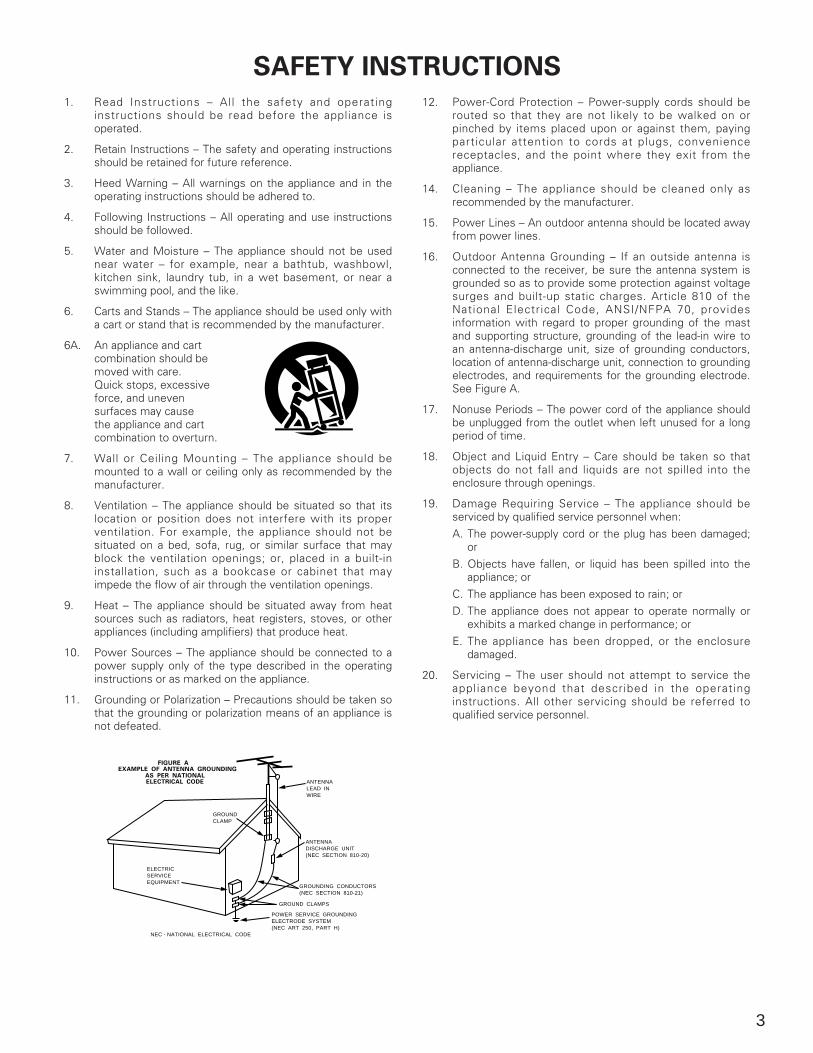
SAFETY INSTRUCTIONS
1. Read Instructions – All the safety and operatinginstructions should be read before the appliance isoperated.
2. Retain Instructions – The safety and operating instructionsshould be retained for future reference.
3. Heed Warning – All warnings on the appliance and in theoperating instructions should be adhered to.
4. Following Instructions – All operating and use instructionsshould be followed.
5. Water and Moisture – The appliance should not be usednear water – for example, near a bathtub, washbowl,kitchen sink, laundry tub, in a wet basement, or near aswimming pool, and the like.
6. Carts and Stands – The appliance should be used only witha cart or stand that is recommended by the manufacturer.
6A. An appliance and cartcombination should be moved with care.Quick stops, excessive force, and unevensurfaces may causethe appliance and cart combination to overturn.
7. Wall or Ceiling Mounting – The appliance should bemounted to a wall or ceiling only as recommended by themanufacturer.
8. Ventilation – The appliance should be situated so that itslocation or position does not interfere with its properventilation. For example, the appliance should not besituated on a bed, sofa, rug, or similar surface that mayblock the ventilation openings; or, placed in a built-ininstallation, such as a bookcase or cabinet that mayimpede the flow of air through the ventilation openings.
9. Heat – The appliance should be situated away from heatsources such as radiators, heat registers, stoves, or otherappliances (including amplifiers) that produce heat.
10. Power Sources – The appliance should be connected to apower supply only of the type described in the operatinginstructions or as marked on the appliance.
11. Grounding or Polarization – Precautions should be taken sothat the grounding or polarization means of an appliance isnot defeated.
12. Power-Cord Protection – Power-supply cords should berouted so that they are not likely to be walked on orpinched by items placed upon or against them, payingparticular attention to cords at plugs, conveniencereceptacles, and the point where they exit from theappliance.
14. Cleaning – The appliance should be cleaned only asrecommended by the manufacturer.
15. Power Lines – An outdoor antenna should be located awayfrom power lines.
16. Outdoor Antenna Grounding – If an outside antenna isconnected to the receiver, be sure the antenna system isgrounded so as to provide some protection against voltagesurges and built-up static charges. Article 810 of theNational Electrical Code, ANSI/NFPA 70, providesinformation with regard to proper grounding of the mastand supporting structure, grounding of the lead-in wire toan antenna-discharge unit, size of grounding conductors,location of antenna-discharge unit, connection to groundingelectrodes, and requirements for the grounding electrode.See Figure A.
17. Nonuse Periods – The power cord of the appliance shouldbe unplugged from the outlet when left unused for a longperiod of time.
18. Object and Liquid Entry – Care should be taken so thatobjects do not fall and liquids are not spilled into theenclosure through openings.
19. Damage Requiring Service – The appliance should beserviced by qualified service personnel when:A. The power-supply cord or the plug has been damaged;
orB. Objects have fallen, or liquid has been spilled into the
appliance; orC. The appliance has been exposed to rain; orD. The appliance does not appear to operate normally or
exhibits a marked change in performance; orE. The appliance has been dropped, or the enclosure
damaged.
20. Servicing – The user should not attempt to service theappliance beyond that described in the operatinginstructions. All other servicing should be referred toqualified service personnel.
FIGURE AEXAMPLE OF ANTENNA GROUNDING
AS PER NATIONALELECTRICAL CODE ANTENNA
LEAD INWIRE
GROUNDCLAMP
ELECTRICSERVICEEQUIPMENT
ANTENNADISCHARGE UNIT(NEC SECTION 810-20)
GROUNDING CONDUCTORS(NEC SECTION 810-21)
GROUND CLAMPS
POWER SERVICE GROUNDINGELECTRODE SYSTEM(NEC ART 250, PART H)
NEC - NATIONAL ELECTRICAL CODE
4
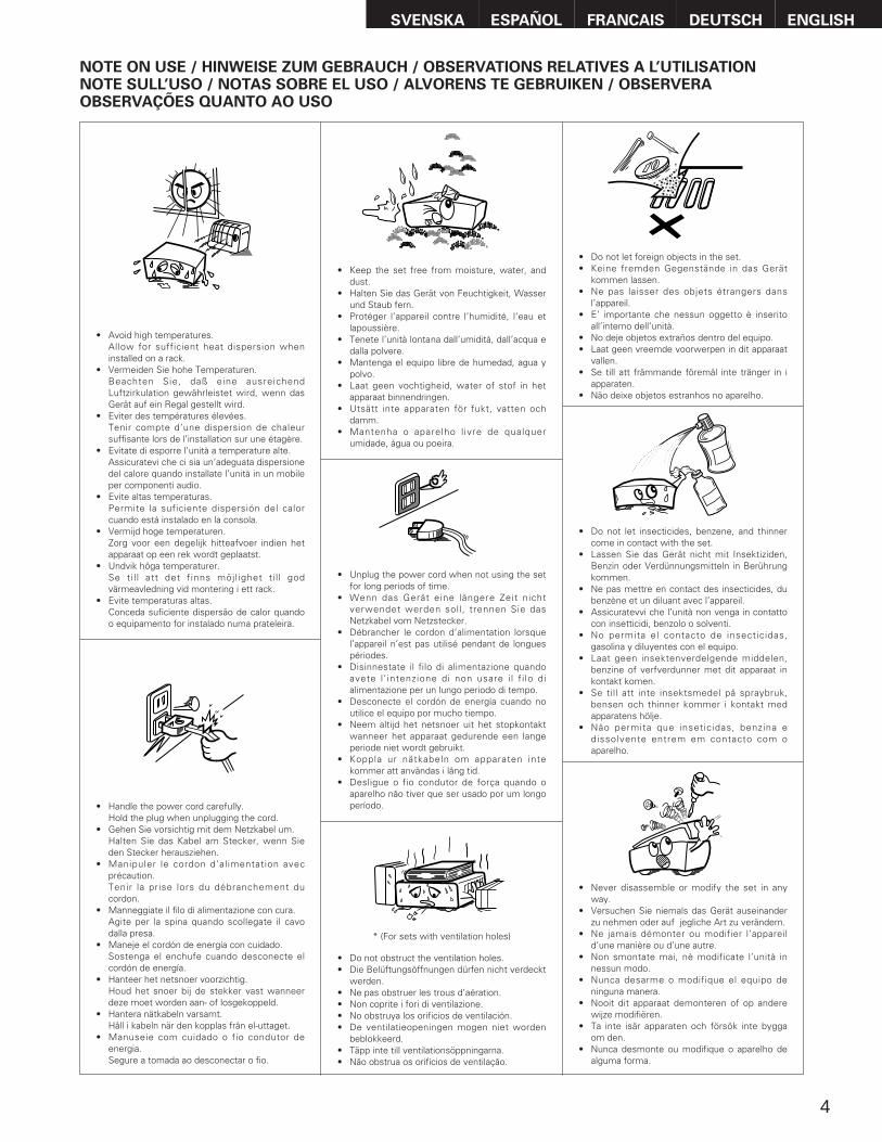
NOTE ON USE / HINWEISE ZUM GEBRAUCH / OBSERVATIONS RELATIVES A L’UTILISATIONNOTE SULL’USO / NOTAS SOBRE EL USO / ALVORENS TE GEBRUIKEN / OBSERVERAOBSERVAÇÕES QUANTO AO USO
• Avoid high temperatures.Allow for sufficient heat dispersion wheninstalled on a rack.
• Vermeiden Sie hohe Temperaturen.Beachten Sie, daß eine ausreichendLuftzirkulation gewährleistet wird, wenn dasGerät auf ein Regal gestellt wird.
• Eviter des températures élevées.Tenir compte d’une dispersion de chaleursuffisante lors de l’installation sur une étagère.
• Evitate di esporre l’unità a temperature alte.Assicuratevi che ci sia un’adeguata dispersionedel calore quando installate l’unità in un mobileper componenti audio.
• Evite altas temperaturas.Permite la suficiente dispersión del calorcuando está instalado en la consola.
• Vermijd hoge temperaturen.Zorg voor een degelijk hitteafvoer indien hetapparaat op een rek wordt geplaatst.
• Undvik höga temperaturer.Se ti l l att det finns möjl ighet ti l l godvärmeavledning vid montering i ett rack.
• Evite temperaturas altas.Conceda suficiente dispersão de calor quandoo equipamento for instalado numa prateleira.
• Keep the set free from moisture, water, anddust.
• Halten Sie das Gerät von Feuchtigkeit, Wasserund Staub fern.
• Protéger l’appareil contre l’humidité, l’eau etlapoussière.
• Tenete l’unità lontana dall’umidità, dall’acqua edalla polvere.
• Mantenga el equipo libre de humedad, agua ypolvo.
• Laat geen vochtigheid, water of stof in hetapparaat binnendringen.
• Utsätt inte apparaten för fukt, vatten ochdamm.
• Mantenha o aparelho l ivre de qualquerumidade, água ou poeira.
• Do not let foreign objects in the set.• Keine fremden Gegenstände in das Gerät
kommen lassen.• Ne pas laisser des objets étrangers dans
l’appareil.• E’ importante che nessun oggetto è inserito
all’interno dell’unità.• No deje objetos extraños dentro del equipo.• Laat geen vreemde voorwerpen in dit apparaat
vallen.• Se till att främmande föremål inte tränger in i
apparaten.• Não deixe objetos estranhos no aparelho.
• Do not let insecticides, benzene, and thinnercome in contact with the set.
• Lassen Sie das Gerät nicht mit Insektiziden,Benzin oder Verdünnungsmitteln in Berührungkommen.
• Ne pas mettre en contact des insecticides, dubenzène et un diluant avec l’appareil.
• Assicuratevvi che l’unità non venga in contattocon insetticidi, benzolo o solventi.
• No permita el contacto de insecticidas,gasolina y diluyentes con el equipo.
• Laat geen insektenverdelgende middelen,benzine of verfverdunner met dit apparaat inkontakt komen.
• Se till att inte insektsmedel på spraybruk,bensen och thinner kommer i kontakt medapparatens hölje.
• Não permita que inseticidas, benzina edissolvente entrem em contacto com oaparelho.
• Never disassemble or modify the set in anyway.
• Versuchen Sie niemals das Gerät auseinanderzu nehmen oder auf jegliche Art zu verändern.
• Ne jamais démonter ou modifier l’appareild’une manière ou d’une autre.
• Non smontate mai, nè modificate l’unità innessun modo.
• Nunca desarme o modifique el equipo deninguna manera.
• Nooit dit apparaat demonteren of op anderewijze modifiëren.
• Ta inte isär apparaten och försök inte byggaom den.
• Nunca desmonte ou modifique o aparelho dealguma forma.
• Unplug the power cord when not using the setfor long periods of time.
• Wenn das Gerät eine längere Zeit nichtverwendet werden soll, trennen Sie dasNetzkabel vom Netzstecker.
• Débrancher le cordon d’alimentation lorsquel’appareil n’est pas utilisé pendant de longuespériodes.
• Disinnestate il filo di alimentazione quandoavete l’ intenzione di non usare i l f i lo dialimentazione per un lungo periodo di tempo.
• Desconecte el cordón de energía cuando noutilice el equipo por mucho tiempo.
• Neem altijd het netsnoer uit het stopkontaktwanneer het apparaat gedurende een langeperiode niet wordt gebruikt.
• Koppla ur nätkabeln om apparaten intekommer att användas i lång tid.
• Desligue o fio condutor de força quando oaparelho não tiver que ser usado por um longoperíodo.
* (For sets with ventilation holes)
• Do not obstruct the ventilation holes.• Die Belüftungsöffnungen dürfen nicht verdeckt
werden.• Ne pas obstruer les trous d’aération.• Non coprite i fori di ventilazione.• No obstruya los orificios de ventilación.• De ventilatieopeningen mogen niet worden
beblokkeerd.• Täpp inte till ventilationsöppningarna.• Não obstrua os orifícios de ventilação.
• Handle the power cord carefully.Hold the plug when unplugging the cord.
• Gehen Sie vorsichtig mit dem Netzkabel um.Halten Sie das Kabel am Stecker, wenn Sieden Stecker herausziehen.
• Manipuler le cordon d’alimentation avecprécaution.Tenir la prise lors du débranchement ducordon.
• Manneggiate il filo di alimentazione con cura.Agite per la spina quando scollegate il cavodalla presa.
• Maneje el cordón de energía con cuidado. Sostenga el enchufe cuando desconecte elcordón de energía.
• Hanteer het netsnoer voorzichtig.Houd het snoer bij de stekker vast wanneerdeze moet worden aan- of losgekoppeld.
• Hantera nätkabeln varsamt.Håll i kabeln när den kopplas från el-uttaget.
• Manuseie com cuidado o fio condutor deenergia.Segure a tomada ao desconectar o fio.
ENGLISHDEUTSCHFRANCAISESPAÑOLSVENSKA
5
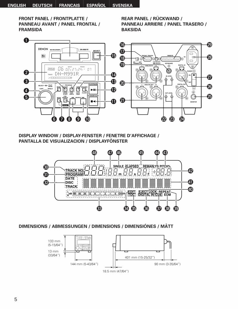
FRONT PANEL / FRONTPLATTE /
PANNEAU AVANT / PANEL FRONTAL /
FRAMSIDA
REAR PANEL / RÜCKWAND /
PANNEAU ARRIERE / PANEL TRASERO /
BAKSIDA
DISPLAY WINDOW / DISPLAY-FENSTER / FENETRE D’AFFICHAGE /
PANTALLA DE VISUALIZACION / DISPLAYFÖNSTER
DIMENSIONS / ABMESSUNGEN / DIMENSIONS / DIMENSIÓNES / MÅTT
133 mm(5-15/64”)
13 mm(33/64”)
144 mm (5-43/64”)
18.5 mm (47/64”)
401 mm (15-25/32”)
90 mm (3-35/64”)
ENGLISH DEUTSCH FRANCAIS ESPAÑOL SVENSKA
6
The DN-M991R MD recorder is a table-top type MD recorder designed for use in broadcast stations, for productions, etc.
Recording Functions
• Auto Level Rec start
This function automatically starts the recording operation when an audio signal level from an external unit connected to the DN-M991R exceedsthe preset level (–36 to –66 dB, 6 steps) * You can turn off this function.
• Auto Track Increment
DN-M991R detects the silent portion of the program material and automatically increases the track number. The level of the silent portion canbe set within a range of –36 to –66 dB (6 steps).
• Stereo/Mono recording (74/148 min.)
Playback Functions
• Using CUE Signals to make searches (Up to 5 points per track)
• Track Search Select knob (Easy track selection)
• Program Play (Max. 25 tracks)
Program can be stored in the preset memory.• Play mode and Finish mode
1) Play mode q Continuous: Play a whole disc w Single: Play a track2) Finish mode (Stop, Next, Recue, Repeat)
q Stop: Stop after finishing to play a track.w Next: Standby at the beginning of next track after finishing to play a track.e Recue: After finishing to play a track, standby at the beginning of the track.r Repeat: The tracks are repeated according to the play mode.
• Auto Cue
After a track is selected it is automatically cued to the point where audio starts.Cueing tracks place at the point where audio starts rather than where the track starts. The level at which sound is first detected can be setbetween –36 to –72 dB (7 steps).
• End Monitor
Pressing the END MON button during standby instantly previews the end of the track, thus assuring perfect “outros”. The point at whichmonitoring starts can be set within a range of 5 to 35 seconds (7 steps) prior to the track’s end.
• End Of Message (EOM)
At the end of a track, the EOM flashes, providing a visual warning to the operator that the track will end shortly. The point at which the flashingbegins can be set within a range of 5 to 35 seconds (7 steps) prior to the end of the track.
• Pitch Control (Preset) (+8.0 to –8.0 %, 0.1 step)
• Instant Start (Playback starts less than 0.01 seconds after the PLAY button is pressed.)
Editing Functions
• Editing
1) Basic Editing• DIVIDE: Smallest edited unit is 11.6 msec (1 sound group) • ERASE TRACK/ERASE DISC/ERASE CUE• COMBINE • MOVE • DISC’s Pitch • TRACK NAME • DISC NAMEUp to 100 characters can be used for each name, however, the combined total number of characters cannot exceed 1700.
2) Cue signals also can be edited. (Can be erased, rewritten, or added to later.)• Undo function
Undo function during editing (Up to 2 editing operations prior to the most recent one can be undone.)• SCMS
Recording is possible without reception of the copy defeat restriction. Writing of the copy defeat code is selectable.
Functions for Systematization
• Rich Array of External Control Terminals
Serial Remote. (RS232C/RS422A switchcable, D-sub 9 pin)Parallel Remote. (D-sub 25 pin)
• Easy operations from IBM-PCTM compatible keyboard
• PS/2 keyboard connector is equipped on the rear panel.• Keyboard (PS/2 connector, US keyboard with 101 or 104 keys recommended) can be connected to perform playback, recording, program
input, editing, hot start and other operations.• Hot Start function (Parallel remote, serial remote, keyboard)
• Hot start is possible for up to 10 tracks.• Tracks can be loaded into Hot Start by detecting the Auto Cue Level (–72/–66/–60/–54/–48/–42/–36 dB selectable in Preset mode).• Sound can be loaded into Hot Start from any track location.• Loaded tracks can be replaced with new tracks.• Seamless Loop can be used during Hot Start playback.• Hot Start operation is possible using parallel remote, serial remote or a keyboard (PS/2 connector, US keyboard with 101 or 104 keys
recommended).
Other Functions
• Large FL Display, Illuminated Button
• Sampling Rate Convertor
• Digital input is possible at 32 and 48 kHz as well as 44.1 kHz.• If input occurs at 32 or 48 kHz, it is automatically converted to 44.1 kHz during recording.
MAIN FEATURES
ENGLISH
7
ENGLISH
CONTENTS
z PART NAMES AND FUNCTIONS ……………………………8 ~ 11(1) Front Panel ……………………………………………………8, 9(2) Rear Panel……………………………………………………9, 10(3) Display Window……………………………………………10, 11
x REMOTE CONTROL CONNECTIONS ………………………11, 12
c ABOUT MINIDISCS …………………………………………………12
v PRESET FUNCTIONS AND OPERATIONS …………………13 ~ 17(1) List of Preset Functions ………………………………………13(2) Presetting Procedure …………………………………………14(3) Detailed Description of Preset Functions ……………15 ~ 17
b BASIC OPERATION …………………………………………18 ~ 22(1) Starting Playback ……………………………………………18(2) End Monitor ……………………………………………………18(3) PLAY/PAUSE and STANDBY/CUE Operations ……………19(4) Before Starting to Record ……………………………………19(5) Method of Recording on Discs ………………………………19(6) Starting to Record ……………………………………………20(7) Stopping Recording ……………………………………………20(8) Starting Recording Automatically by
Detecting the Input Level ……………………………………21(9) Incrementing Track Numbers…………………………………22(10) Pre-UTOC Function ……………………………………………22
n HANDY OPERATIONS ………………………………………23 ~ 25(1) Setting Cue Points ……………………………………………23(2) Direct Search for Cue Points …………………………………24(3) Instantaneous play (Hot Start) ………………………………25
m PROGRAMMED PLAYBACK …………………………………26 ~ 28(1) Inputting Programs ……………………………………………26(2) Changing Programs ………………………………………26, 27 (3) Playing Programs ………………………………………………27(4) Presetting Programs …………………………………………28
, EDITING FUNCTIONS…………………………………………29 ~ 35(1) Editing Functions ………………………………………………29(2) Editing Function Select ………………………………………30(3) Erasing Cue Signals ‹Cue erase function› …………………30(4) Erasing Tracks ‹Track erase function› ………………………31(5) Erasing All the Tracks on the Disc ‹All erase function› ……31(6) Dividing Tracks into Two Parts ‹Divide function›……………32(7) Combining Two Tracks ‹Combine function›…………………32(8) Moving Tracks ‹Move function› ………………………………33(9) Pitch on the disc (Disc’s pitch function) ……………………33(10) Inputting (Changing) Names ‹Title function› ………………34(11) Exit the Edit Mode or Undoing Editing ‹Undo functions› …35
. CONNECTING AND OPERATING A KEYBOARD ……………36, 37(1) Connecting the Keyboard ……………………………………36(2) Keyboard Operations ……………………………………36, 37
⁄0 RESETTING THE MICROPROCESSOR …………………………38
⁄1 HANDLING CARTRIDGES …………………………………………38(1) Cautions on Handling …………………………………………38(2) Cautions on Storing ……………………………………………38
⁄2 MESSAGES …………………………………………………………39
⁄3 SYSTEM LIMITATIONS ……………………………………………40(1) Track Number Limits …………………………………………40(2) Recording Time Limits ………………………………………40(3) Editing Function Limits ………………………………………40(4) Title Function Limits …………………………………………40(5) Other Limits ……………………………………………………40
⁄4 SPECIFICATIONS ……………………………………………………41
Checking the ContentsCheck that the carton contains the following items:
3P power supply cord ……………………………………………1 pc.Operating instructions (this booklet) ……………………………1 pc.
Installing the UnitsUp to three units can be installed in a 19” EIA rack or console. Install shelves on the rack.
NOTES:
• DECLARATION OF CONFORMITYWe declare under our sole responsibility that this product, to which this declaration relates, is inconformity with the following standards:EN60065, EN55013, EN55020, EN61000-3-2 and EN61000-3-3.Following the provisions of 73/23/EEC, 89/336/EEC and 93/68/EEC Directive.
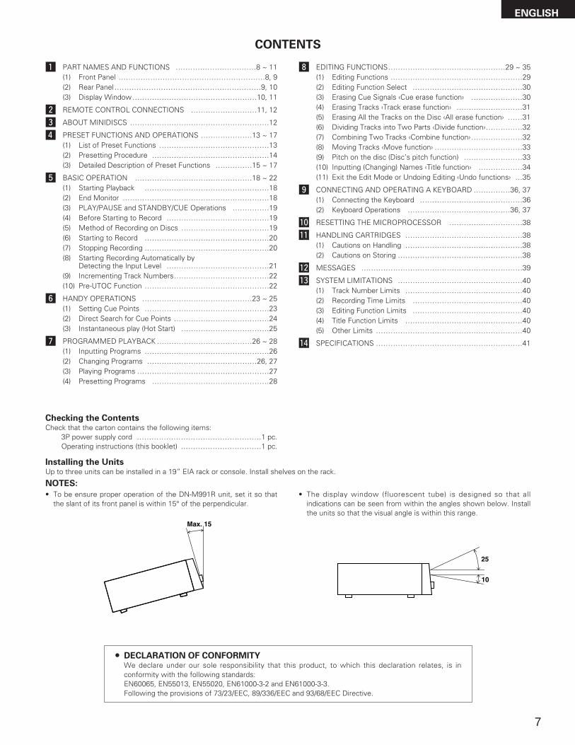
• To be ensure proper operation of the DN-M991R unit, set it so thatthe slant of its front panel is within 15° of the perpendicular.
• The display window (fluorescent tube) is designed so that allindications can be seen from within the angles shown below. Installthe units so that the visual angle is within this range.
8
ENGLISH
1 PART NAMES AND FUNCTIONS
(1) Front Panel
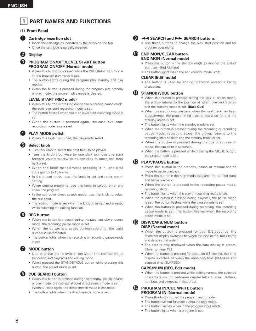
q Cartridge insertion slot
• Insert the cartridge as indicated by the arrow on the top.• Once the cartridge is partially inserted.
w Display
e PROGRAM ON/OFF/LEVEL START button
PROGRAM ON/OFF (Normal mode)
• When this button is pressed while the PROGRAM IN button islit, the program play mode is set.
• The button lights during the program play standby and playmodes.
• When the button is pressed during the program play standbyor play mode, the program play mode is cleared.
LEVEL START (REC mode)
• When this button is pressed during the recording pause mode,the auto level start recording mode is set.
• The button flashes when the auto level start recording mode isset.
• When the button is pressed again, the auto level startrecording mode is canceled.
r PLAY MODE switch
• When this switch is turned, the play mode select.
t Select knob
• Turn this knob to select the next track to be played.• Turn the knob clockwise by one click to move one track
forward, counterclockwise by one click to move one trackbackward.
• When the knob turned while pressing it in, one clickcorresponds to 10 tracks.
• In the preset mode, use this knob to set and enter presetsetting.
• When setting programs, use this knob to select, enter andcheck the program.
• In the cue point direct search mode, use this knob to selectthe cue point.
• The editing mode is set when the knob is turned and pressedwhile selecting the editing function.
y REC button
• When this button is pressed during the stop, standby or pausemode, the recording pause mode is set.
• When the button is pressed during recording, the tracknumber is incremented.
• The button lights when the recording or recording pause modeis set
u MODE button
• Use this button to switch between the normal mode(recording and playback) and editing mode.
• When pressed the STANDBY/CUE button while pressing thisbutton, the preset mode is set.
i CUE SEARCH button
• When this button is pressed during the standby, pause, searchor play mode, the cue signal point direct search mode is set.When pressed again, the direct search mode is canceled.
• The button lights when the direct search mode is set.
o 6 SEARCH and 7 SEARCH buttons
• Use these buttons to change the play start position and forprogram operations.
!0 END MON/CLEAR button
END MON (Normal mode)
• Press this button in the standby mode to monitor the end ofthe track. (End Monitor)
• The button lights when the end monitor mode is set.
CLEAR (Edit mode)
• The button is used for editing operation and for clearingcharacters.
!1 STANDBY/CUE button
• When this button is pressed during the play or pause mode,the pickup returns to the position at which playback startedand the standby mode is set. (Back Cue)
• When pressed during playback when the next track has beenprogrammed, the programmed track is searched for and thestandby mode is set.
• The button lights when the standby mode is set.• When the button is pressed during the recording or recording
pause mode, recording stops, the pickup returns to therecording start position and the standby mode is set.
• When the button is pressed during the cue direct searchmode, the cue point is searched.
• When the button is pressed while pressing the MODE button,the preset mode is set.
!2 PLAY/PAUSE button
• Press this button in the standby, pause or manual searchmode to begin playback.
• Press the button in the stop mode to search for the first trackand begin playback.
• When the button is pressed in the recording pause mode,recording starts.
• The button lights when the play or recording mode is set.• When the button is pressed during playback, the pause mode
is set. The button flashes while the pause mode is set.• When the button is pressed during recording, the recording
pause mode is set. The button flashes when the recordingpause mode is set.
!3 DISP/CAPS/NUM button
DISP (Normal mode)
• When the button is pressed for over 0.5 seconds, thecharacter display switches between the disc name, track nameand date, in that order.
• The date is only displayed when the date display is preset.(Refer to Page 13.)
• When the button is pressed for less than 0.5 second, the timedisplay switches between the remaining time (REMAIN) andelapsed time (ELAPSED).
CAPS/NUM (REC, Edit mode)
• When the button is pressed while editing names, the selectedcharacters switch between capital letters, small letters,numbers and symbols, in that order.
!4 PROGRAM IN/CUE WRITE button
PROGRAM IN (Normal mode)
• Press this button to set the program input mode.• The button will not function during the play mode.• The button flashes when in the program input mode.• The button lights when a program is set.
9
ENGLISH
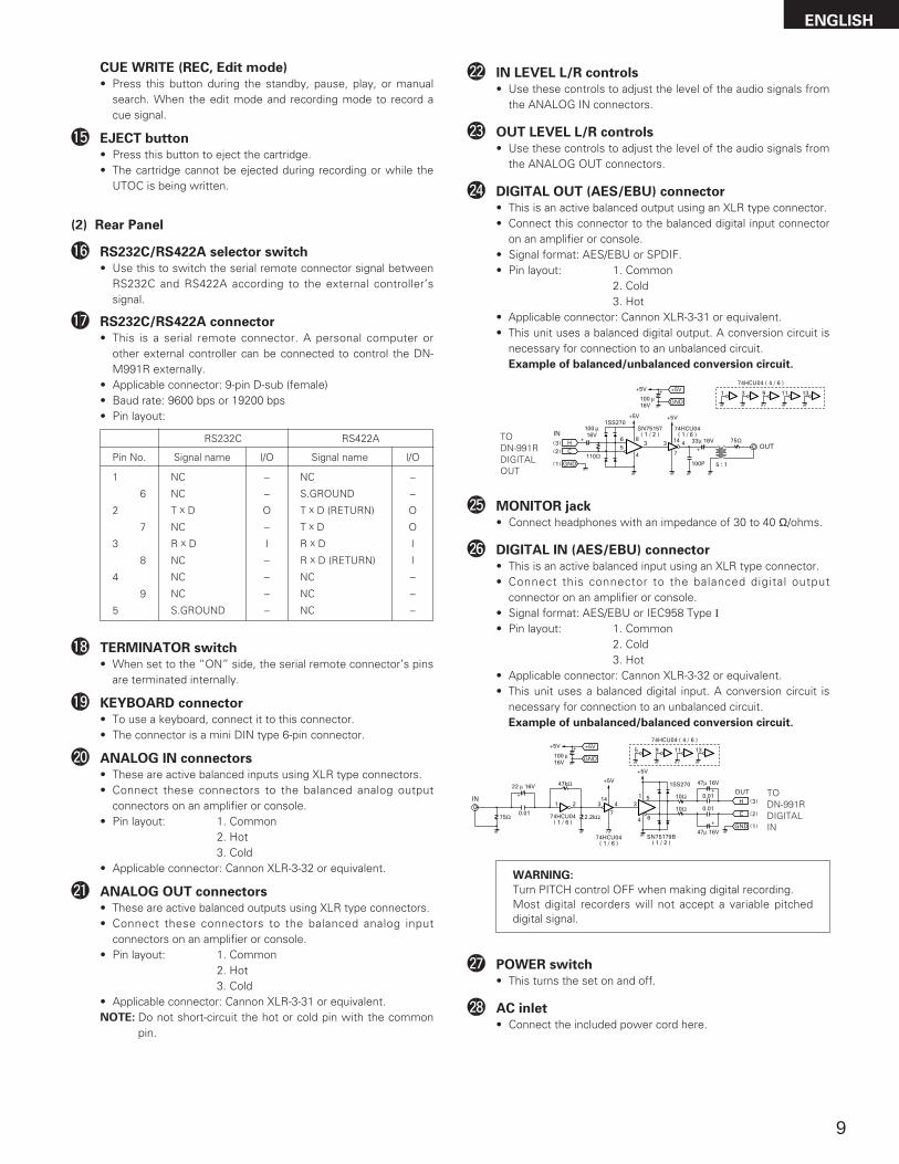
!6 RS232C/RS422A selector switch
• Use this to switch the serial remote connector signal betweenRS232C and RS422A according to the external controller’ssignal.
!7 RS232C/RS422A connector
• This is a serial remote connector. A personal computer orother external controller can be connected to control the DN-M991R externally.
• Applicable connector: 9-pin D-sub (female)• Baud rate: 9600 bps or 19200 bps• Pin layout:
@2 IN LEVEL L/R controls
• Use these controls to adjust the level of the audio signals fromthe ANALOG IN connectors.
@3 OUT LEVEL L/R controls
• Use these controls to adjust the level of the audio signals fromthe ANALOG OUT connectors.
@4 DIGITAL OUT (AES/EBU) connector
• This is an active balanced output using an XLR type connector.• Connect this connector to the balanced digital input connector
on an amplifier or console.• Signal format: AES/EBU or SPDIF.• Pin layout: 1. Common
2. Cold3. Hot
• Applicable connector: Cannon XLR-3-31 or equivalent.• This unit uses a balanced digital output. A conversion circuit is
necessary for connection to an unbalanced circuit.Example of balanced/unbalanced conversion circuit.
CUE WRITE (REC, Edit mode)
• Press this button during the standby, pause, play, or manualsearch. When the edit mode and recording mode to record acue signal.
!5 EJECT button
• Press this button to eject the cartridge.• The cartridge cannot be ejected during recording or while the
UTOC is being written.
+5V
GND
OUT75Ω33µ 16V+
+33
4
865
4
7
14
11931
74HCU04( 1 / 6 )
74HCU04 ( 4 / 6 )
SN75157( 1 / 2 )
110Ω
1SS270+5V +5V
100 µ16V
100 µ16V
++5V
HC
GND
( )3( )2
( )1
IN
100P 5 : 1
13
Pin No.
1
6
2
7
3
8
4
9
5
Signal name
NC
NC
T x D
NC
R x D
NC
NC
NC
S.GROUND
I/O
–
–
O
–
I
–
–
–
–
I/O
–
–
O
O
I
I
–
–
–
Signal name
NC
S.GROUND
T x D (RETURN)
T x D
R x D
R x D (RETURN)
NC
NC
NC
RS422A
(2) Rear Panel
RS232C
!8 TERMINATOR switch
• When set to the “ON” side, the serial remote connector’s pinsare terminated internally.
!9 KEYBOARD connector
• To use a keyboard, connect it to this connector.• The connector is a mini DIN type 6-pin connector.
@0 ANALOG IN connectors
• These are active balanced inputs using XLR type connectors.• Connect these connectors to the balanced analog output
connectors on an amplifier or console.• Pin layout: 1. Common
2. Hot3. Cold
• Applicable connector: Cannon XLR-3-32 or equivalent.
@1 ANALOG OUT connectors
• These are active balanced outputs using XLR type connectors.• Connect these connectors to the balanced analog input
connectors on an amplifier or console.• Pin layout: 1. Common
2. Hot3. Cold
• Applicable connector: Cannon XLR-3-31 or equivalent.NOTE: Do not short-circuit the hot or cold pin with the common
pin.
TODN-991RDIGITALOUT
@5 MONITOR jack
• Connect headphones with an impedance of 30 to 40 Ω/ohms.
@6 DIGITAL IN (AES/EBU) connector
• This is an active balanced input using an XLR type connector.• Connect this connector to the balanced digital output
connector on an amplifier or console.• Signal format: AES/EBU or IEC958 Type I• Pin layout: 1. Common
2. Cold3. Hot
• Applicable connector: Cannon XLR-3-32 or equivalent.• This unit uses a balanced digital input. A conversion circuit is
necessary for connection to an unbalanced circuit.Example of unbalanced/balanced conversion circuit.
TODN-991RDIGITALIN
WARNING:
Turn PITCH control OFF when making digital recording.Most digital recorders will not accept a variable pitcheddigital signal.
@7 POWER switch
• This turns the set on and off.
@8 AC inlet
• Connect the included power cord here.
10
ENGLISH
(3) Display Window
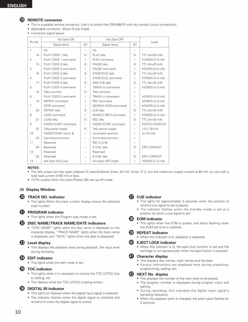
#0 TRACK NO. indicator
• This lights When the track number display shows the selectedtrack number.
#1 PROGRAM indicator
• This lights when the Program play mode is set.
#2 DISC NAME/TRACK NAME/DATE indicators
• “DISC NAME” lights when the disc name is displayed on thecharacter display, “TRACK NAME” lights when the track nameis displayed, and “DATE” lights when the date is displayed.
#3 Level display
• This displays the playback level during playback, the input levelduring recording.
#4 EDIT indicator
• This lights when the edit mode is set.
#5 TOC indicator
• This lights when it is necessary to rewrite the TOC (UTOC) dueto editing, etc
• This flashes while the TOC (UTOC) is being written.
#6 DIGITAL IN indicator
• This lights (or flashes) when the digital input signal is selected.• The indicator flashes when the digital signal is unlocked and
remains lit when the digital signal is locked.
NOTES:
• The tally output pin has open collector IC specifications (Imax. 20 mA, Vmax. 5 V), but the maximum supply current is 80 mA, so use with atotal load current of 80 mA or less.
• 13 Pin enable when Hot start (Preset 36)) set up off mode.
Pin No.
1
14
2
15
3
16
4
17
5
18
6
19
7
20
8
21
9
22
10
23
11
24
12
25
13
Signal name I/OLevel
FG
PLAY CODE 1 tally
PLAY CODE 1 command
PLAY CODE 2 tally
PLAY CODE 2 command
PLAY CODE 3 tally
PLAY CODE 3 command
PLAY CODE 4 tally
PLAY CODE 4 command
Tally common
PLAY CODE 5 command
REPEAT command
STOP command
REPEAT tally
LOAD command
LOAD tally
FADER START command
Tally power supply
FADER START return &
Command common
Reserved
Reserved
Reserved
Reserved
Hot Start ON (Low)
–
O
I
O
I
O
I
O
I
–
I
I
I
O
I
O
I
–
–
–
–
O
–
O
I
TTL (lol=20 mA)
HCMOS (li–3 mA)
TTL (lol=20 mA)
HCMOS (li–3 mA)
TTL (lol=20 mA)
HCMOS (li–3 mA)
TTL (lol=20 mA)
HCMOS (li–3 mA)
HCMOS (li–3 mA)
HCMOS (li–3 mA)
HCMOS (li–3 mA)
TTL (lol=20 mA)
HCMOS (li–3 mA)
TTL (lol=20 mA)
PHOTO COUPLER
+5 V, 20 mA
(li=10 mA)
DRY CONTACT
DRY CONTACT
HCMOS (li–3 mA)
@9 REMOTE connector
• This is a parallel remote connector. Use it to control the DN-M991R with dry contact circuit connections.• Applicable connector: 25-pin D-sub (male)• Connector signal layout:
Signal name
FG
PLAY tally
PLAY command
PAUSE tally
PAUSE command
STDBY/CUE tally
STDBY/CUE command
END CUE tally
TRACK (+) command
Tally common
TRACK (–) command
REC command
SEARCH (FWD) command
CUE tally
SEARCH (REV) command
REC tally
FADER START command
Tally power supply
Command common
Command common
REC E.O.M.
E.O.M. tally
Reserved
E.O.M. tally
Hot Start OFF (High)
Hot Start OFF
I/O
–
O
I
O
I
O
I
O
I
O
I
I
I
O
I
O
–
O
–
–
–
–
–
–
–
#7 CUE indicator• This lights for approximately 3 seconds when the position at
which a cue signal is set is played.• The indicator flashes when the standby mode is set at a
position at which a cue signal is set.
#8 EOM indicator• This lights when the EOM is preset, and starts flashing when
the EOM set time is reached.
#9 REPEAT indicator• When this indicator is lit, playback is repeated.
$0 EJECT LOCK indicator• When this indicator is lit, the eject lock function is set and the
cartridge is not ejected even when the eject button is pressed.
$1 Character display• This displays disc names, track names and the date.• Various instructions are displayed here during presetting,
programming, editing, etc.
$2 NEXT No. display• This displays the number of the next track to be played.• The program number is displayed during program input and
editing.• During recording, this indicates the digital input signal’s
sampling frequency.• When the playback pitch is changed, the pitch value flashes for
3 seconds.
Hot Start ON
11
ENGLISH
H
L
H
L
H
L
H
L
H
L
X
H
SW. No.
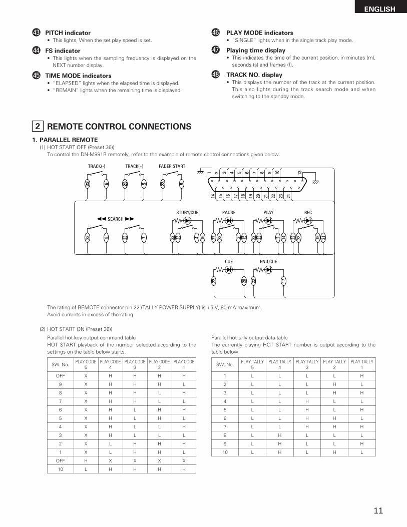
$3 PITCH indicator
• This lights, When the set play speed is set.
$4 FS indicator
• This lights when the sampling frequency is displayed on theNEXT number display.
$5 TIME MODE indicators
• “ELAPSED” lights when the elapsed time is displayed.• “REMAIN” lights when the remaining time is displayed.
REMOTE CONTROL CONNECTIONS
$6 PLAY MODE indicators
• “SINGLE” lights when in the single track play mode.
$7 Playing time display
• This indicates the time of the current position, in minutes (m),seconds (s) and frames (f).
$8 TRACK NO. display
• This displays the number of the track at the current position.This also lights during the track search mode and whenswitching to the standby mode.
1. PARALLEL REMOTE
(1) HOT START OFF (Preset 36))To control the DN-M991R remotely, refer to the example of remote control connections given below.
The rating of REMOTE connector pin 22 (TALLY POWER SUPPLY) is +5 V, 80 mA maximum.Avoid currents in excess of the rating.
(2) HOT START ON (Preset 36))
PLAY CODE5
PLAY CODE4
PLAY CODE3
PLAY CODE2
PLAY CODE1
OFF
9
8
7
6
5
4
3
2
1
OFF
10
X
X
X
X
X
X
X
X
X
X
H
L
H
H
H
H
H
H
H
H
L
L
X
H
H
H
H
H
L
L
L
L
H
H
X
H
H
H
L
L
H
H
L
L
H
H
X
H
PLAY TALLY5
PLAY TALLY4
PLAY TALLY3
PLAY TALLY2
PLAY TALLY1SW. No.
1
2
3
4
5
6
7
8
9
10
L
L
L
L
L
L
L
L
L
L
L
L
L
L
L
L
L
H
H
H
L
L
L
H
H
H
H
L
L
L
L
H
H
L
L
H
H
L
L
H
H
L
H
L
H
L
H
L
H
L
Parallel hot key output command tableHOT START playback of the number selected according to thesettings on the table below starts.
Parallel hot tally output data tableThe currently playing HOT START number is output according to thetable below.
2
12
ENGLISH
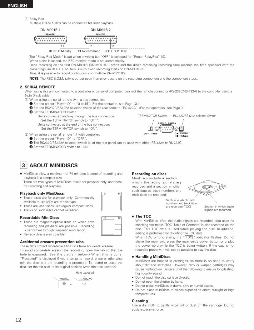
ABOUT MINIDISCS
2 MiniDiscs allow a maximum of 74 minutes (stereo) of recording andplayback in a compact size.There are two types of MiniDiscs: those for playback only, and thosefor recording and playback.
Recordable MiniDiscs• These are magneto-optical discs on which both
recording and playback are possible. Recordingis performed through magnetic modulation.
• Re-recording is also possible.
Accidental erasure prevention tabsThese tabs protect recordable MiniDiscs from accidental erasure.To avoid accidentally erasing the recording, open the tab so that thehole is exposed. (See the diagram below.) When this is done,“Protected” is displayed if you attempt to record, erase or otherwiseedit the disc, and the recording is protected. To record or erase thedisc, set the tab back to its original position (with the hole covered).
Recording on discsMiniDiscs include a section inwhich the audio signals arerecorded and a section in whichsuch data as track numbers andtrack titles are recorded.
2 The TOCWith MiniDiscs, after the audio signals are recorded, data used forchecking the tracks (TOC–Table of Contents) is also recorded on thedisc. This TOC data is used when playing the disc. In addition,editing is performed by rewriting the TOC data.When TOC writing starts, the “ ” indicator flashes. Do notshake the main unit, press the main unit’s power button or unplugthe power cord while the TOC is being written. If the data is notrecorded properly, it will not be possible to play the disc.
2 Handling MiniDiscsMiniDiscs are housed in cartridges, so there is no need to worryabout dirt and scratches. However, dirty or warped cartridges maycause malfunction. Be careful of the following to ensure long-lasting,high quality sound:
• Do not touch the disc surface directly.• Do not open the shutter by hand.• Do not place MiniDiscs in dusty, dirty or humid places.• Do not place MiniDiscs in places exposed to direct sunlight or high
temperatures.
CleaningUse a dry cloth to gently wipe dirt or dust off the cartridge. Do notapply excessive force.
TOC
Section in which audiosignals are recorded
Hole exposed
(3) Relay RecMultiple DN-M991R’s can be connected for relay playback.
REMOTE
DN-M991R-1REMOTE
DN-M991R-2
REC E.O.M. tally REC E.O.M. tallyPLAY command
11 2 11
2. SERIAL REMOTEWhen using this unit connected to a controller or personal computer, connect the remote connector (RS-232C/RS-422A) to the controller using a9-pin D-sub cable.(1) When using the serial remote with a bus connection.
q Set the preset “Player ID” to “0 to 15”. (For the operation, see Page 13.)w Set the RS232C/RS422A selector switch of the rear panel to “RS-422A”. (For the operation, see Page 9.)e Set the TERMINATOR switch.
Units connected midway through the bus connection:Set the TERMINATOR switch to “OFF”.
Units connected at the end of the bus connection:Set the TERMINATOR switch to “ON”.
(2) When using the serial remote 1:1 with controller.q Set the preset “Player ID” to “OFF”.w The RS232C/RS422A selector switch (a) of the rear panel can be used with either RS-422A or RS-232C.e Set the TERMINATOR switch to “ON”.
The “Relay Red Mode” is set when anything but “OFF” is selected for “Preset RelayRec” 19).When a disc is loaded, the REC monitor mode is set automatically.Once recording on the first DN-M991R (DN-M991R-1) starts and the disc’s remaining recording time reaches the time specified with thepresettings, an REC E.O.M. tally is output and recording starts on DN-M991R-2.Thus, it is possible to record continuously on multiple DN-M991R’s.
NOTE: The REC E.O.M. tally is output even if an error occurs on the recording component and the component stops.
RS232C / RS422A
OFFON RS232CRS422A
TERMINATOR Switch RS232C/RS422A selector Switch
3
Playback only MiniDiscs• These discs are for playback only. Commercially
available music MDs are of this type.• These are laser discs, like regular compact discs.• Tracks on such discs cannot be edited.
Section in which tracknumbers and track titlesare recorded (TOC)
13
ENGLISH
PLAYBACK
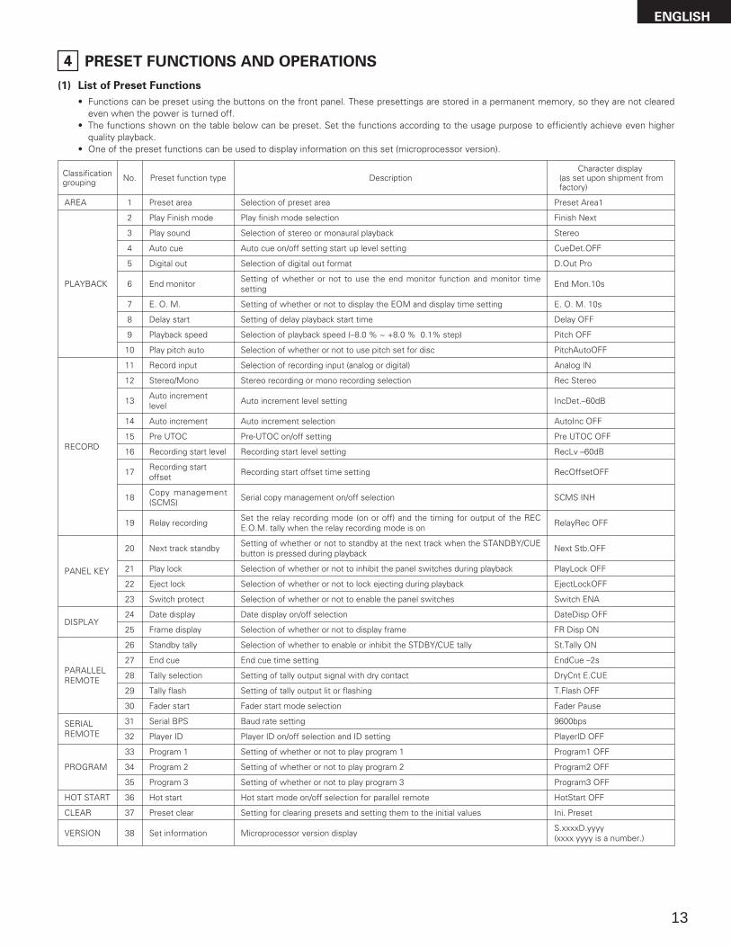
PRESET FUNCTIONS AND OPERATIONS
(1) List of Preset Functions
• Functions can be preset using the buttons on the front panel. These presettings are stored in a permanent memory, so they are not clearedeven when the power is turned off.
• The functions shown on the table below can be preset. Set the functions according to the usage purpose to efficiently achieve even higherquality playback.
• One of the preset functions can be used to display information on this set (microprocessor version).
Preset function type DescriptionCharacter display
(as set upon shipment from factory)
No.
Preset area Selection of preset area Preset Area1
Setting of whether or not to use the end monitor function and monitor timesetting
Setting of whether or not to display the EOM and display time setting
PlayLock OFF
S.xxxxD.yyyy (xxxx yyyy is a number.)Set information Microprocessor version display
Classification grouping
1
7
8
9
10
11
12
13
14
15
16
17
18
19
20
21
22
23
24
25
26
27
28
29
30
31
32
33
34
35
37
38
2
3
4
5
6
AREA
Play Finish mode Play finish mode selection Finish Next
Play sound Selection of stereo or monaural playback Stereo
Auto cue Auto cue on/off setting start up level setting CueDet.OFF
Digital out Selection of digital out format D.Out Pro
End monitor End Mon.10s
E. O. M. E. O. M. 10s
Delay start Setting of delay playback start time Delay OFF
Playback speed Selection of playback speed (–8.0 % ~ +8.0 % 0.1% step) Pitch OFF
Play pitch auto Selection of whether or not to use pitch set for disc PitchAutoOFF
RECORD
Record input Selection of recording input (analog or digital) Analog IN
Stereo/Mono Stereo recording or mono recording selection Rec Stereo
Auto incrementlevel Auto increment level setting IncDet.–60dB
Auto increment Auto increment selection AutoInc OFF
Pre UTOC Pre-UTOC on/off setting Pre UTOC OFF
Recording start level Recording start level setting RecLv –60dB
Recording startoffset Recording start offset time setting RecOffsetOFF
Copy management(SCMS) Serial copy management on/off selection SCMS INH
Relay recording Set the relay recording mode (on or off) and the timing for output of the RECE.O.M. tally when the relay recording mode is on RelayRec OFF
PANEL KEY
Next track standby Setting of whether or not to standby at the next track when the STANDBY/CUEbutton is pressed during playback Next Stb.OFF
Play lock Selection of whether or not to inhibit the panel switches during playback
Eject lock Selection of whether or not to lock ejecting during playback EjectLockOFF
Switch protect Selection of whether or not to enable the panel switches Switch ENA
DISPLAYDate display Date display on/off selection DateDisp OFF
Frame display Selection of whether or not to display frame FR Disp ON
PARALLELREMOTE
Standby tally Selection of whether to enable or inhibit the STDBY/CUE tally St.Tally ON
End cue End cue time setting EndCue –2s
Tally selection Setting of tally output signal with dry contact DryCnt E.CUE
Tally flash Setting of tally output lit or flashing T.Flash OFF
Fader start Fader start mode selection Fader Pause
SERIALREMOTE
Serial BPS Baud rate setting 9600bps
Player ID Player ID on/off selection and ID setting PlayerID OFF
PROGRAM
Program 1 Setting of whether or not to play program 1 Program1 OFF
Program 2 Setting of whether or not to play program 2 Program2 OFF
Program 3 Setting of whether or not to play program 3 Program3 OFF
CLEAR Preset clear Setting for clearing presets and setting them to the initial values Ini. Preset
36HOT START Hot start Hot start mode on/off selection for parallel remote HotStart OFF
VERSION
4
14
ENGLISH
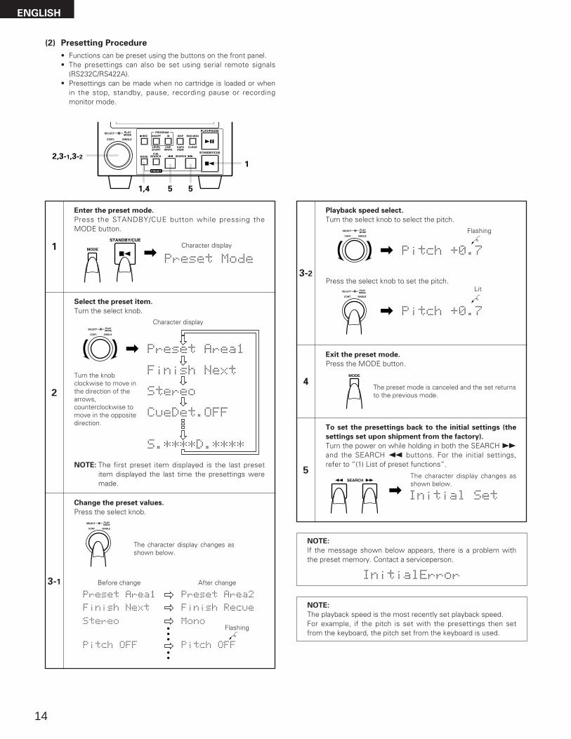
(2) Presetting Procedure
• Functions can be preset using the buttons on the front panel.• The presettings can also be set using serial remote signals
(RS232C/RS422A).• Presettings can be made when no cartridge is loaded or when
in the stop, standby, pause, recording pause or recordingmonitor mode.
1
4
Exit the preset mode.
Press the MODE button.MODE
5
To set the presettings back to the initial settings (the
settings set upon shipment from the factory).
Turn the power on while holding in both the SEARCH 7and the SEARCH 6 buttons. For the initial settings,refer to “(1) List of preset functions”.
3-1
Change the preset values.
Press the select knob.
2
Select the preset item.
Turn the select knob.
NOTE: The first preset item displayed is the last presetitem displayed the last time the presettings weremade.
Character display
Character display
The character display changes asshown below.
Before change After change
The preset mode is canceled and the set returnsto the previous mode.
The character display changes asshown below.
NOTE:
If the message shown below appears, there is a problem withthe preset memory. Contact a serviceperson.
Flashing
3-2
Playback speed select.
Turn the select knob to select the pitch.
Flashing
Lit
InitialError
NOTE:
The playback speed is the most recently set playback speed.For example, if the pitch is set with the presettings then setfrom the keyboard, the pitch set from the keyboard is used.
Enter the preset mode.
Press the STANDBY/CUE button while pressing theMODE button.
Turn the knobclockwise to move inthe direction of thearrows,counterclockwise tomove in the oppositedirection.
Press the select knob to set the pitch.
15
ENGLISH
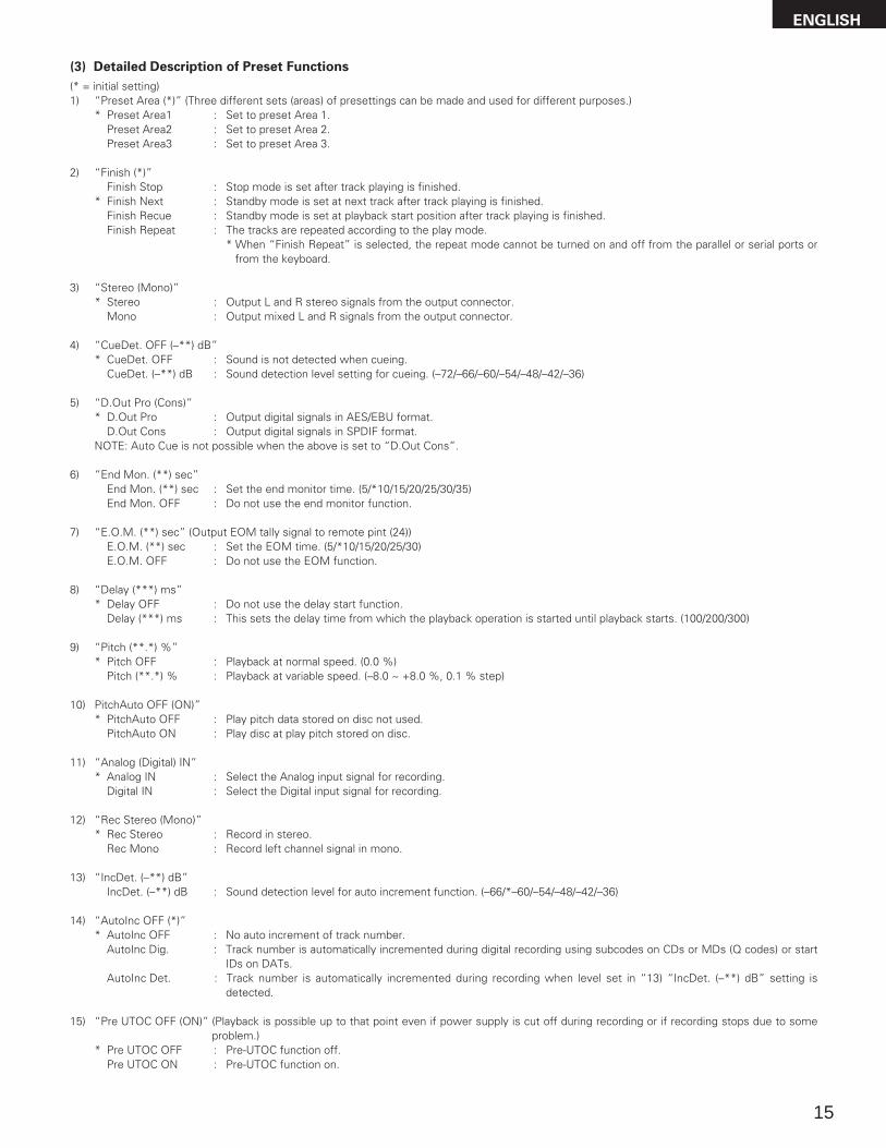
(3) Detailed Description of Preset Functions
(* = initial setting)1) “Preset Area (*)” (Three different sets (areas) of presettings can be made and used for different purposes.)
* Preset Area1 : Set to preset Area 1.Preset Area2 : Set to preset Area 2.Preset Area3 : Set to preset Area 3.
2) “Finish (*)”Finish Stop : Stop mode is set after track playing is finished.
* Finish Next : Standby mode is set at next track after track playing is finished.Finish Recue : Standby mode is set at playback start position after track playing is finished.Finish Repeat : The tracks are repeated according to the play mode.
* When “Finish Repeat” is selected, the repeat mode cannot be turned on and off from the parallel or serial ports orfrom the keyboard.
3) “Stereo (Mono)”* Stereo : Output L and R stereo signals from the output connector.
Mono : Output mixed L and R signals from the output connector.
4) “CueDet. OFF (–**) dB”* CueDet. OFF : Sound is not detected when cueing.
CueDet. (–**) dB : Sound detection level setting for cueing. (–72/–66/–60/–54/–48/–42/–36)
5) “D.Out Pro (Cons)”* D.Out Pro : Output digital signals in AES/EBU format.
D.Out Cons : Output digital signals in SPDIF format.NOTE: Auto Cue is not possible when the above is set to “D.Out Cons”.
6) “End Mon. (**) sec”End Mon. (**) sec : Set the end monitor time. (5/*10/15/20/25/30/35)End Mon. OFF : Do not use the end monitor function.
7) “E.O.M. (**) sec” (Output EOM tally signal to remote pint (24))E.O.M. (**) sec : Set the EOM time. (5/*10/15/20/25/30)E.O.M. OFF : Do not use the EOM function.
8) “Delay (***) ms”* Delay OFF : Do not use the delay start function.
Delay (***) ms : This sets the delay time from which the playback operation is started until playback starts. (100/200/300)
9) “Pitch (**.*) %”* Pitch OFF : Playback at normal speed. (0.0 %)
Pitch (**.*) % : Playback at variable speed. (–8.0 ~ +8.0 %, 0.1 % step)
10) PitchAuto OFF (ON)”* PitchAuto OFF : Play pitch data stored on disc not used.
PitchAuto ON : Play disc at play pitch stored on disc.
11) “Analog (Digital) IN”* Analog IN : Select the Analog input signal for recording.
Digital IN : Select the Digital input signal for recording.
12) “Rec Stereo (Mono)”* Rec Stereo : Record in stereo.
Rec Mono : Record left channel signal in mono.
13) “IncDet. (–**) dB”IncDet. (–**) dB : Sound detection level for auto increment function. (–66/*–60/–54/–48/–42/–36)
14) “AutoInc OFF (*)”* AutoInc OFF : No auto increment of track number.
AutoInc Dig. : Track number is automatically incremented during digital recording using subcodes on CDs or MDs (Q codes) or startIDs on DATs.
AutoInc Det. : Track number is automatically incremented during recording when level set in “13) “IncDet. (–**) dB” setting isdetected.
15) “Pre UTOC OFF (ON)” (Playback is possible up to that point even if power supply is cut off during recording or if recording stops due to someproblem.)
* Pre UTOC OFF : Pre-UTOC function off.Pre UTOC ON : Pre-UTOC function on.
16
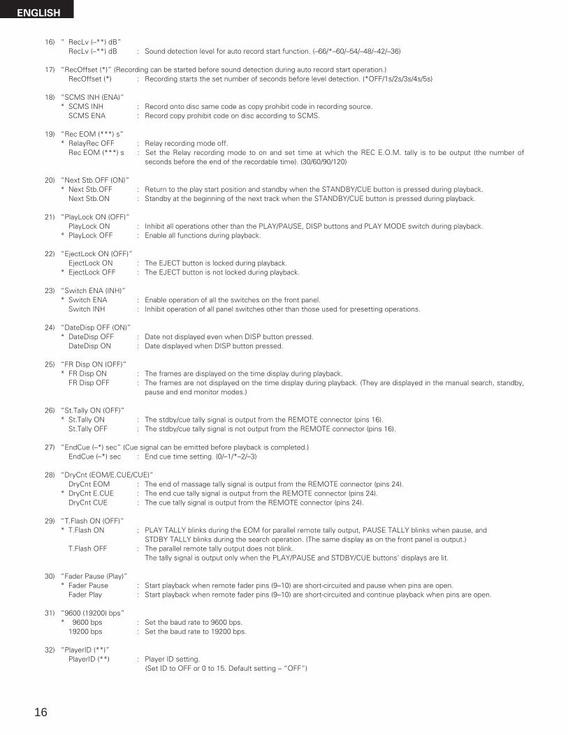
ENGLISH
16) “ RecLv (–**) dB”RecLv (–**) dB : Sound detection level for auto record start function. (–66/*–60/–54/–48/–42/–36)
17) “RecOffset (*)” (Recording can be started before sound detection during auto record start operation.)RecOffset (*) : Recording starts the set number of seconds before level detection. (*OFF/1s/2s/3s/4s/5s)
18) “SCMS INH (ENA)”* SCMS INH : Record onto disc same code as copy prohibit code in recording source.
SCMS ENA : Record copy prohibit code on disc according to SCMS.
19) “Rec EOM (***) s”* RelayRec OFF : Relay recording mode off.
Rec EOM (***) s : Set the Relay recording mode to on and set time at which the REC E.O.M. tally is to be output (the number ofseconds before the end of the recordable time). (30/60/90/120)
20) “Next Stb.OFF (ON)”* Next Stb.OFF : Return to the play start position and standby when the STANDBY/CUE button is pressed during playback.
Next Stb.ON : Standby at the beginning of the next track when the STANDBY/CUE button is pressed during playback.
21) “PlayLock ON (OFF)”PlayLock ON : Inhibit all operations other than the PLAY/PAUSE, DISP buttons and PLAY MODE switch during playback.
* PlayLock OFF : Enable all functions during playback.
22) “EjectLock ON (OFF)”EjectLock ON : The EJECT button is locked during playback.
* EjectLock OFF : The EJECT button is not locked during playback.
23) “Switch ENA (INH)”* Switch ENA : Enable operation of all the switches on the front panel.
Switch INH : Inhibit operation of all panel switches other than those used for presetting operations.
24) “DateDisp OFF (ON)”* DateDisp OFF : Date not displayed even when DISP button pressed.
DateDisp ON : Date displayed when DISP button pressed.
25) “FR Disp ON (OFF)”* FR Disp ON : The frames are displayed on the time display during playback.
FR Disp OFF : The frames are not displayed on the time display during playback. (They are displayed in the manual search, standby,pause and end monitor modes.)
26) “St.Tally ON (OFF)”* St.Tally ON : The stdby/cue tally signal is output from the REMOTE connector (pins 16).
St.Tally OFF : The stdby/cue tally signal is not output from the REMOTE connector (pins 16).
27) “EndCue (–*) sec” (Cue signal can be emitted before playback is completed.)EndCue (–*) sec : End cue time setting. (0/–1/*–2/–3)
28) “DryCnt (EOM/E.CUE/CUE)”DryCnt EOM : The end of massage tally signal is output from the REMOTE connector (pins 24).
* DryCnt E.CUE : The end cue tally signal is output from the REMOTE connector (pins 24).DryCnt CUE : The cue tally signal is output from the REMOTE connector (pins 24).
29) “T.Flash ON (OFF)”* T.Flash ON : PLAY TALLY blinks during the EOM for parallel remote tally output, PAUSE TALLY blinks when pause, and
STDBY TALLY blinks during the search operation. (The same display as on the front panel is output.)T.Flash OFF : The parallel remote tally output does not blink.
The tally signal is output only when the PLAY/PAUSE and STDBY/CUE buttons’ displays are lit.
30) “Fader Pause (Play)”* Fader Pause : Start playback when remote fader pins (9–10) are short-circuited and pause when pins are open.
Fader Play : Start playback when remote fader pins (9–10) are short-circuited and continue playback when pins are open.
31) “9600 (19200) bps”* 09600 bps : Set the baud rate to 9600 bps.
19200 bps : Set the baud rate to 19200 bps.
32) “PlayerID (**)”PlayerID (**) : Player ID setting.
(Set ID to OFF or 0 to 15. Default setting – “OFF”)
17
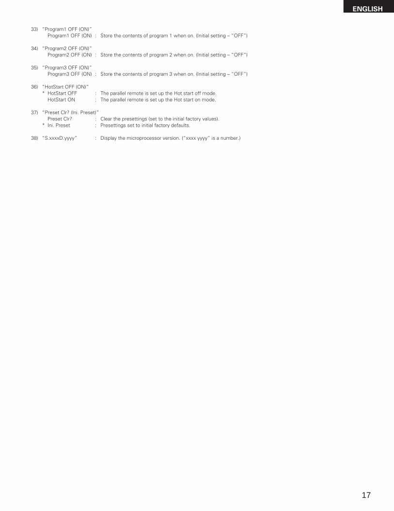
ENGLISH
33) “Program1 OFF (ON)”Program1 OFF (ON) : Store the contents of program 1 when on. (Initial setting – “OFF”)
34) “Program2 OFF (ON)”Program2 OFF (ON) : Store the contents of program 2 when on. (Initial setting – “OFF”)
35) “Program3 OFF (ON)”Program3 OFF (ON) : Store the contents of program 3 when on. (Initial setting – “OFF”)
36) “HotStart OFF (ON)”* HotStart OFF : The parallel remote is set up the Hot start off mode.
HotStart ON : The parallel remote is set up the Hot start on mode.
37) “Preset Clr? (Ini. Preset)”Preset Clr? : Clear the presettings (set to the initial factory values).
* Ini. Preset : Presettings set to initial factory defaults.
38) “S.xxxxD.yyyy” : Display the microprocessor version. (“xxxx yyyy” is a number.)
18
ENGLISH
BASIC OPERATION
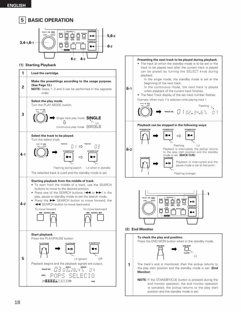
(1) Starting Playback
1
2
Make the presettings according to the usage purpose.
(See Page 13.)
NOTE: Steps 1, 2 and 3 can be performed in the oppositeorder.
3
4-1
Select the play mode.
Turn the PLAY MODE switch.
Load the cartridge.
Single track play mode
Continuous play mode
Select the track to be played.
Turn the select knob.
The selected track is cued and the standby mode is set.
Flashing during search Lit when in standby
1
To check the play end position.
Press the END MON button when in the standby mode.
The track’s end is monitored, then the pickup returns tothe play start position and the standby mode is set. (End
Monitor)
NOTE: If the STANDBY/CUE button is pressed during theend monitor operation, the end monitor operationis canceled, the pickup returns to the play startposition and the standby mode is set.
(2) End Monitor
6-2
Playback can be stopped in the following ways:
Playback is interrupted, the pickup returnsto the play start position and the standbymode is set. (BACK CUE)
Lit
Lit
Flashing (orange)
Lit
Playback is interrupted and thepause mode is set at that point.
Flashing
4-2
Starting playback from the middle of track.
• To start from the middle of a track, use the SEARCHbuttons to move to the desired position.
• Press one of the SEARCH buttons (6 or 7) in theplay, pause or standby mode to set the search mode.
• Press the 7 SEARCH button to move forward, the6 SEARCH button to move backward.
To move forward To move backward
5
Start playback.
Press the PLAY/PAUSE button.
Lit (green) Off
6-1
Presetting the next track to be played during playback.
• The track at which the standby mode is to be set or thetrack to be played next after the current track is playedcan be preset by turning the SELECT knob duringplayback.
In the single mode, the standby mode is set at thebeginning of the next track.In the continuous mode, the next track is playedwhen playback of the current track finishes.
• The Next Track display of the set track number flashes.
Flashing
Example: When track 7 is selected while playing track 1
5
Playback begins and the playback signals are output.
19
ENGLISH
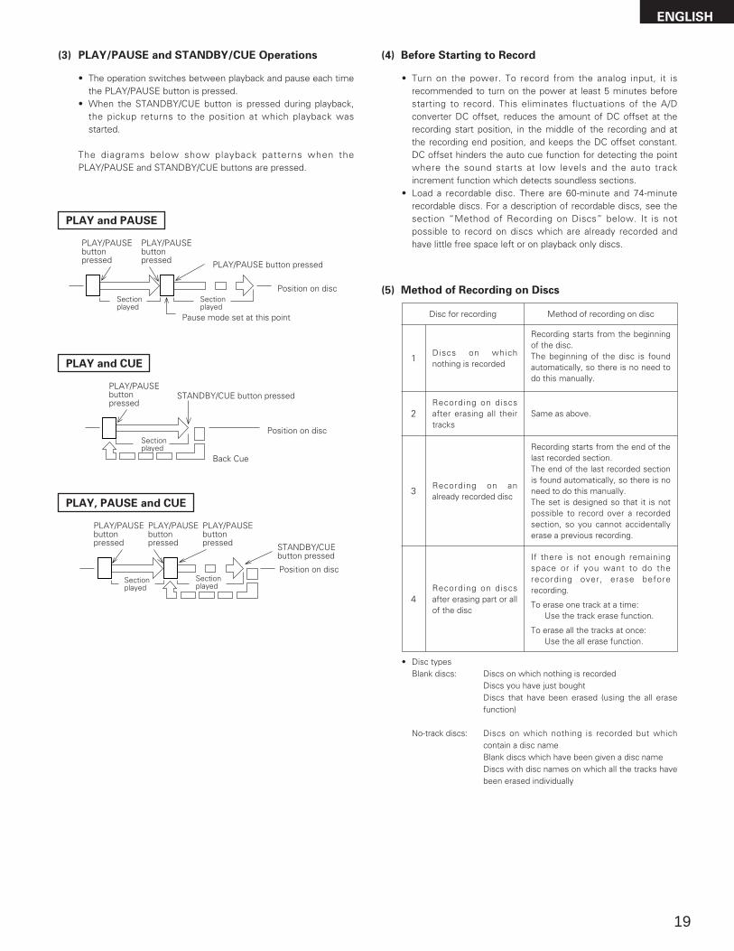
(3) PLAY/PAUSE and STANDBY/CUE Operations (4) Before Starting to Record
(5) Method of Recording on Discs
• The operation switches between playback and pause each timethe PLAY/PAUSE button is pressed.
• When the STANDBY/CUE button is pressed during playback,the pickup returns to the position at which playback wasstarted.
The diagrams below show playback patterns when thePLAY/PAUSE and STANDBY/CUE buttons are pressed.
PLAY and PAUSE
PLAY/PAUSE button pressed
Position on discSection played
Section played
PLAY and CUE
PLAY, PAUSE and CUE
Back Cue
STANDBY/CUE button pressed
Position on disc
STANDBY/CUEbutton pressed
Position on disc
• Turn on the power. To record from the analog input, it isrecommended to turn on the power at least 5 minutes beforestarting to record. This eliminates fluctuations of the A/Dconverter DC offset, reduces the amount of DC offset at therecording start position, in the middle of the recording and atthe recording end position, and keeps the DC offset constant.DC offset hinders the auto cue function for detecting the pointwhere the sound starts at low levels and the auto trackincrement function which detects soundless sections.
• Load a recordable disc. There are 60-minute and 74-minuterecordable discs. For a description of recordable discs, see thesection “Method of Recording on Discs” below. It is notpossible to record on discs which are already recorded andhave little free space left or on playback only discs.
Disc for recording Method of recording on disc
1Discs on whichnothing is recorded
Recording starts from the beginningof the disc.The beginning of the disc is foundautomatically, so there is no need todo this manually.
2Recording on discsafter erasing all theirtracks
Same as above.
3Recording on analready recorded disc
Recording starts from the end of thelast recorded section.The end of the last recorded sectionis found automatically, so there is noneed to do this manually.The set is designed so that it is notpossible to record over a recordedsection, so you cannot accidentallyerase a previous recording.
4Recording on discsafter erasing part or allof the disc
If there is not enough remainingspace or if you want to do therecording over, erase beforerecording.
To erase one track at a time:Use the track erase function.
To erase all the tracks at once:Use the all erase function.
• Disc typesBlank discs: Discs on which nothing is recorded
Discs you have just boughtDiscs that have been erased (using the all erasefunction)
No-track discs: Discs on which nothing is recorded but whichcontain a disc nameBlank discs which have been given a disc nameDiscs with disc names on which all the tracks havebeen erased individually
PLAY/PAUSEbutton pressed
PLAY/PAUSEbutton pressed
PLAY/PAUSEbutton pressed
Pause mode set at this point
Section played
PLAY/PAUSEbutton pressed
PLAY/PAUSEbutton pressed
PLAY/PAUSEbutton pressed
Section played
Section played
20
ENGLISH
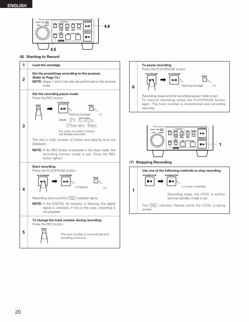
(6) Starting to Record
1
2
Set the presettings according to the purpose.
(Refer to Page 13.)
NOTE: Steps 1 and 2 can also be performed in the reverseorder.
3
Set the recording pause mode.
Press the REC button.
Load the cartridge.
Flashing (orange)
For a disc on which 3 tracks are already recorded.
The disc’s total number of tracks and playing time aredisplayed.
NOTE: If the REC button is pressed in the stop mode, therecording monitor mode is set. (Only the RECbutton lights.)
NOTE: If the DIGITAL IN indicator is flashing, the digitalsignal is unlocked. If this is the case, recording isnot possible.
Lit
4
5
6
Recording starts and the indicator lights.TOC
Start recording.
Press the PLAY/PAUSE button.
To change the track number during recording:
Press the REC button.
To pause recording:
Press the PLAY/PAUSE button.
1
Use one of the following methods to stop recording.
The indicator flashes while the UTOC is beingwritten.
TOC
Recording stops and the recording pause mode is set.To resume recording, press the PLAY/PAUSE buttonagain. The track number is incremented and recordingresumes.
LitLit (green)
The track number is incremented andrecording continues.
LitFlashing (orange)
(7) Stopping Recording
Recording stops, the UTOC is writtenand the standby mode is set.
Lit once in standby
21
ENGLISH
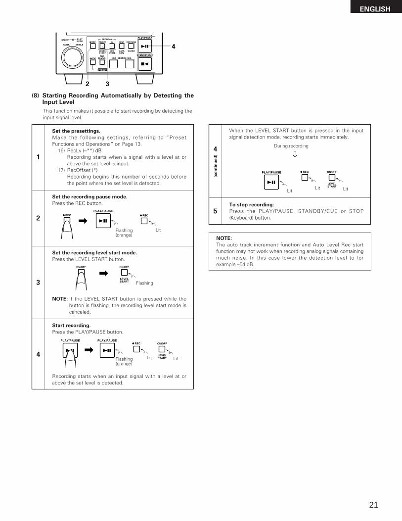
(8) Starting Recording Automatically by Detecting theInput Level
This function makes it possible to start recording by detecting theinput signal level.
1
Set the presettings.
Make the following settings, referring to “PresetFunctions and Operations” on Page 13.
16) RecLv (–**) dBRecording starts when a signal with a level at orabove the set level is input.
17) RecOffset (*)Recording begins this number of seconds beforethe point where the set level is detected.
2
Set the recording pause mode.
Press the REC button.
3
Set the recording level start mode.
Press the LEVEL START button.
4
Start recording.
Press the PLAY/PAUSE button.
Recording starts when an input signal with a level at orabove the set level is detected.
NOTE: If the LEVEL START button is pressed while thebutton is flashing, the recording level start mode iscanceled.
PLAY/PAUSE PLAY/PAUSEREC ON/OFF
LEVELSTART
LitFlashing (orange)
Flashing
Flashing(orange)
LitLit
When the LEVEL START button is pressed in the inputsignal detection mode, recording starts immediately.
5To stop recording:
Press the PLAY/PAUSE, STANDBY/CUE or STOP(Keyboard) button.
PLAY/PAUSE REC ON/OFF
LEVELSTART
LitLit
During recording
NOTE:
The auto track increment function and Auto Level Rec startfunction may not work when recording analog signals containingmuch noise. In this case lower the detection level to forexample –54 dB.
4
(co
nti
nu
ed
)
Lit
22
ENGLISH
(9) Incrementing Track Numbers
During recording, track numbers can be incremented eithermanually or automatically.• Track numbers can be incremented manually in the following
three ways:1) Press the REC button (4) during recording. This increments
the track number.2) Press the PLAY/PAUSE button (13) during recording to
stop recording for that track number and set the recordingpause mode.
3) After recording, use the divide function.
• Track numbers can be incremented automatically in thefollowing three ways, according to the type of input signal:
Input type Method
Analog/digital input Detection of soundless section 1)
Digital input
CDsandMDs
Detection of soundless section 1)
Using the CD’s or MD’s subcodes 2)
Detection of soundless section 1)
Using the DAT’s start IDs 3)DATs
1) Detection of soundless sectionq Make the following two presettings:
• Set “AutoInc OFF” 14) to “AutoInc Det.”• Set the soundless detection level setting to “IncDet. (–60)
dB” 13).w Start playback and recording in such a way that the beginning
of the sound is not missed. When a soundless section (or asection with level lower than the preset soundless detectionlevel setting) of at least 2 continuous seconds is detected,the disc’s track number is automatically incremented.
2 seconds or more
Track number is incrementedSoundless section
NOTE: The auto track increment function may not work whenrecording analog signals containing much noise. In this caselower the detection level to for example –54 dB.
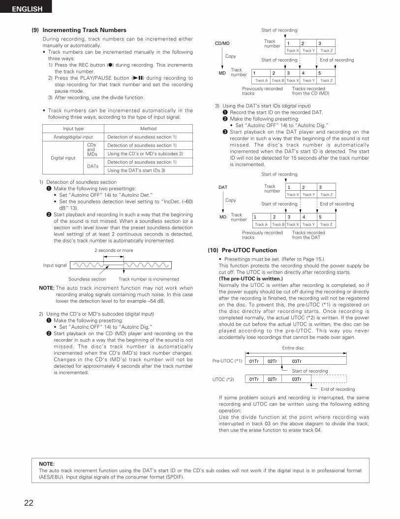
2) Using the CD’s or MD’s subcodes (digital input)q Make the following presetting:
• Set “AutoInc OFF” 14) to “AutoInc Dig.”w Start playback on the CD (MD) player and recording on the
recorder in such a way that the beginning of the sound is notmissed. The disc’s track number is automaticallyincremented when the CD’s (MD’s) track number changes.Changes in the CD’s (MD’s) track number will not bedetected for approximately 4 seconds after the track numberis incremented.
NOTE:
The auto track increment function using the DAT’s start ID or the CD’s sub codes will not work if the digital input is in professional format(AES/EBU). Input digital signals of the consumer format (SPDIF).
Copy
Tracknumber
Track A Track B Track X Track Y Track Z
Previously recordedtracks
Tracks recordedfrom the CD (MD)
Start of recording
Start of recording End of recording
Track X Track Y Track Z
Tracknumber
Tracknumber
Tracknumber
DAT
MD
1 2 3
1 2 3 4 5
Copy
Track A Track B Track X Track Y Track Z
Previously recordedtracks
Tracks recordedfrom the DAT
Start of recording
Start of recording End of recording
Track X Track Y Track Z
3) Using the DAT’s start IDs (digital input)q Record the start ID on the recorded DAT.w Make the following presetting:
• Set “AutoInc OFF” 14) to “AutoInc Dig.”e Start playback on the DAT player and recording on the
recorder in such a way that the beginning of the sound is notmissed. The disc’s track number is automaticallyincremented when the DAT’s start ID is detected. The startID will not be detected for 15 seconds after the track numberis incremented.
(10) Pre-UTOC Function
• Presettings must be set. (Refer to Page 15.)This function protects the recording should the power supply becut off. The UTOC is written directly after recording starts.(The pre-UTOC is written.)
Normally the UTOC is written after recording is completed, so ifthe power supply should be cut off during the recording or directlyafter the recording is finished, the recording will not be registeredon the disc. To prevent this, the pre-UTOC (*1) is registered onthe disc directly after recording starts. Once recording iscompleted normally, the actual UTOC (*2) is written. If the powershould be cut before the actual UTOC is written, the disc can beplayed according to the pre-UTOC. This way you neveraccidentally lose recordings that cannot be made over again.
Pre-UTOC (*1)
Entire disc
Start of recording
End of recording
UTOC (*2)
If some problem occurs and recording is interrupted, the samerecording and UTOC can be written using the following editingoperation:Use the divide function at the point where recording wasinterrupted in track 03 on the above diagram to divide the track,then use the erase function to erase track 04.
Input signal
23
ENGLISH
HANDY OPERATIONS
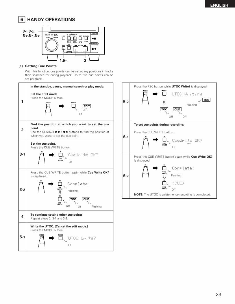
(1) Setting Cue Points
With this function, cue points can be set at any positions in tracksthen searched for during playback. Up to five cue points can beset per track.
1
In the standby, pause, manual search or play mode:
Set the EDIT mode.
Press the MODE button.
2
Find the position at which you want to set the cue
point.
Use the SEARCH 7/6 buttons to find the position atwhich you want to set the cue point.
3-1
Set the cue point.
Press the CUE WRITE button.
EDITMODE MODE
3-2
Press the CUE WRITE button again while Cue Write OK?
is displayed.
4To continue setting other cue points:
Repeat steps 2, 3-1 and 3-2.
Lit
Lit
Flashing
Off Flashing
5-1
Write the UTOC. (Cancel the edit mode.)
Press the MODE button.
5-2
Press the REC button while UTOC Write? is displayed.
6-1
To set cue points during recording:
Press the CUE WRITE button.
6-2
Press the CUE WRITE button again while Cue Write OK?
is displayed.
NOTE: The UTOC is written once recording is completed.
Lit
Flashing
Off Off
Lit
Flashing
6
Lit
Off
24
ENGLISH
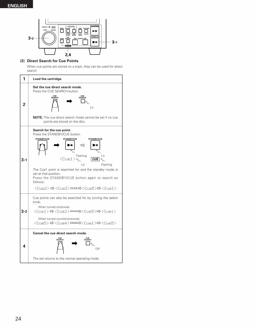
(2) Direct Search for Cue Points
When cue points are stored on a track, they can be used for directsearch.
2
Set the cue direct search mode.
Press the CUE SEARCH button.
NOTE: The cue direct search mode cannot be set if no cuepoints are stored on the disc.
3-1
Search for the cue point.
Press the STANDBY/CUE button.
The Cue1 point is searched for and the standby mode isset at that position.Press the STANDBY/CUE button again to search asfollows:
3-2
Cue points can also be searched for by turning the selectknob.
4
Cancel the cue direct search mode.
The set returns to the normal operating mode.
CUESEARCH
CUESEARCH
Lit
Lit
Lit
Flashing
Flashing
When turned clockwise:
When turned counterclockwise:
Off
1 Load the cartridge.
25
ENGLISH
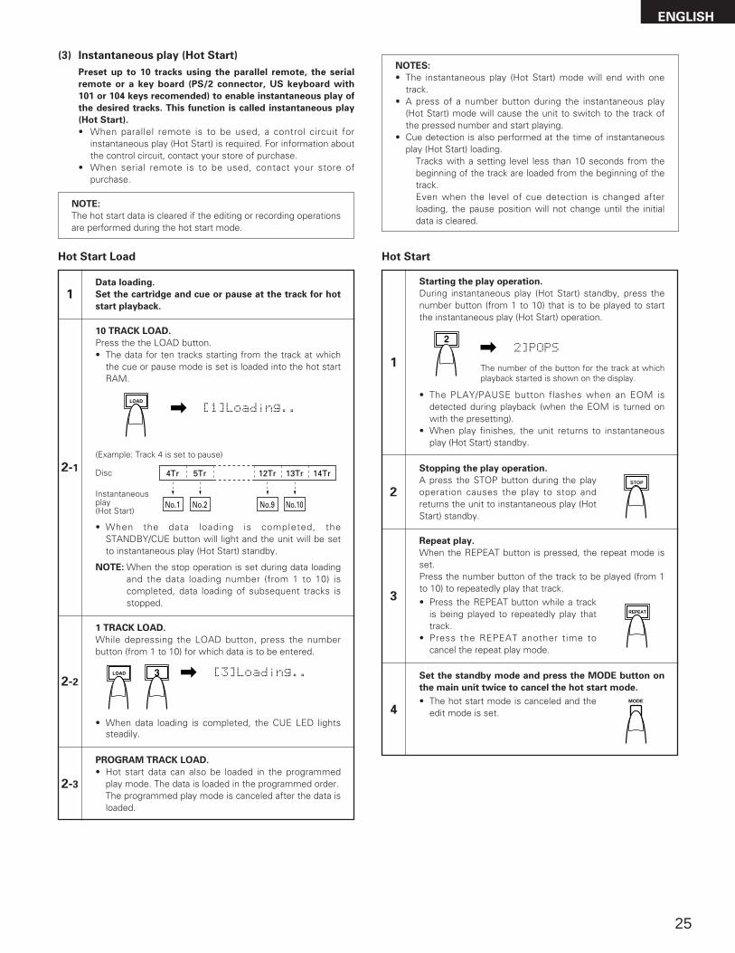
(3) Instantaneous play (Hot Start)
Data loading.
Set the cartridge and cue or pause at the track for hot
start playback.
1
• When the data loading is completed, theSTANDBY/CUE button will light and the unit will be setto instantaneous play (Hot Start) standby.
2
10 TRACK LOAD.
Press the the LOAD button.• The data for ten tracks starting from the track at which
the cue or pause mode is set is loaded into the hot startRAM.
1Starting the play operation.
During instantaneous play (Hot Start) standby, press thenumber button (from 1 to 10) that is to be played to startthe instantaneous play (Hot Start) operation.
NOTE:
The hot start data is cleared if the editing or recording operationsare performed during the hot start mode.
Stopping the play operation.
A press the STOP button during the playoperation causes the play to stop andreturns the unit to instantaneous play (HotStart) standby.
• When data loading is completed, the CUE LED lightssteadily.
PROGRAM TRACK LOAD.
• Hot start data can also be loaded in the programmedplay mode. The data is loaded in the programmed order.The programmed play mode is canceled after the data isloaded.
Preset up to 10 tracks using the parallel remote, the serial
remote or a key board (PS/2 connector, US keyboard with
101 or 104 keys recomended) to enable instantaneous play of
the desired tracks. This function is called instantaneous play
(Hot Start).
• When parallel remote is to be used, a control circuit forinstantaneous play (Hot Start) is required. For information aboutthe control circuit, contact your store of purchase.
• When serial remote is to be used, contact your store ofpurchase.
2-1
Instantaneous play(Hot Start)
Disc
(Example: Track 4 is set to pause)
NOTE: When the stop operation is set during data loadingand the data loading number (from 1 to 10) iscompleted, data loading of subsequent tracks isstopped.
• The PLAY/PAUSE button flashes when an EOM isdetected during playback (when the EOM is turned onwith the presetting).
• When play finishes, the unit returns to instantaneousplay (Hot Start) standby.
1 TRACK LOAD.
While depressing the LOAD button, press the numberbutton (from 1 to 10) for which data is to be entered.
2-2
Repeat play.
When the REPEAT button is pressed, the repeat mode isset.Press the number button of the track to be played (from 1to 10) to repeatedly play that track.• Press the REPEAT button while a track
is being played to repeatedly play thattrack.
• Press the REPEAT another time tocancel the repeat play mode.
3
4
NOTES:
• The instantaneous play (Hot Start) mode will end with onetrack.
• A press of a number button during the instantaneous play(Hot Start) mode will cause the unit to switch to the track ofthe pressed number and start playing.
• Cue detection is also performed at the time of instantaneousplay (Hot Start) loading.
Tracks with a setting level less than 10 seconds from thebeginning of the track are loaded from the beginning of thetrack.Even when the level of cue detection is changed afterloading, the pause position will not change until the initialdata is cleared.
Hot Start Load Hot Start
The number of the button for the track at whichplayback started is shown on the display.
2-3
REPEAT
Set the standby mode and press the MODE button on
the main unit twice to cancel the hot start mode.
• The hot start mode is canceled and theedit mode is set.
MODE
26
ENGLISH
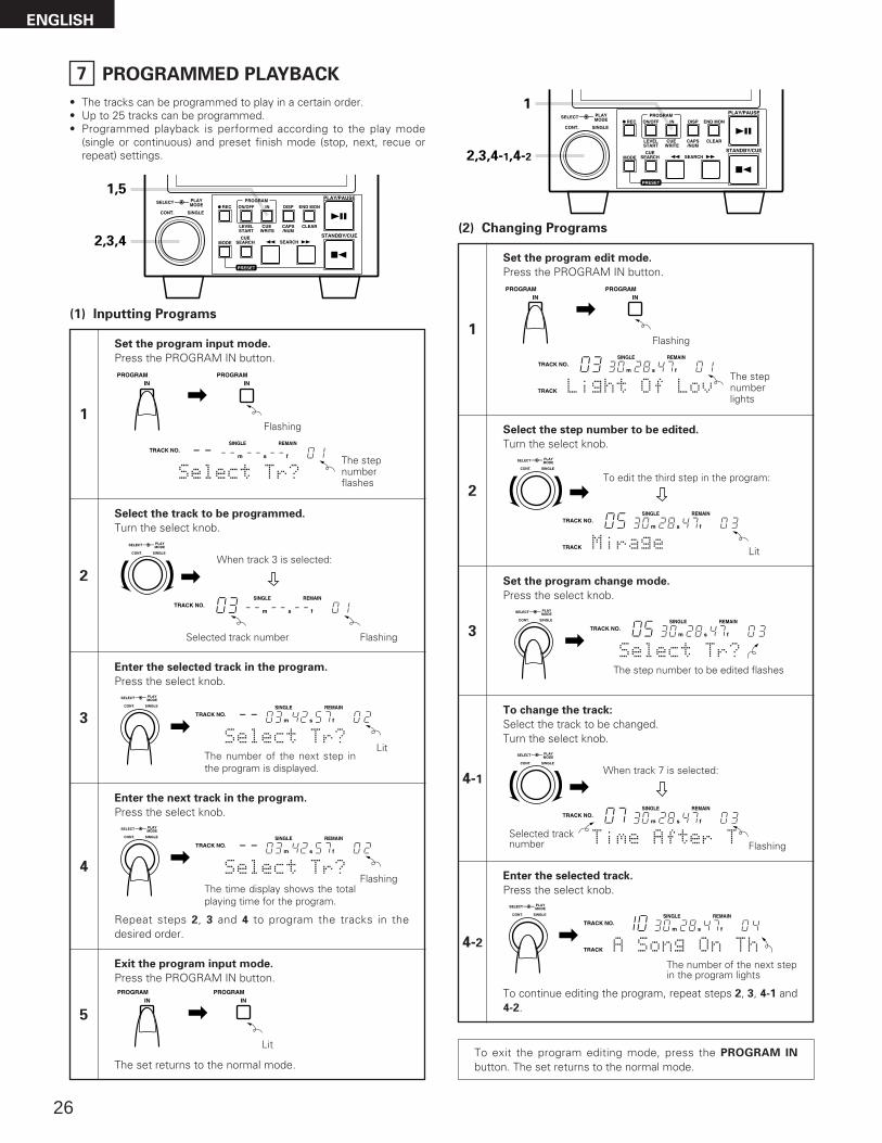
PROGRAMMED PLAYBACK
• The tracks can be programmed to play in a certain order.• Up to 25 tracks can be programmed.• Programmed playback is performed according to the play mode
(single or continuous) and preset finish mode (stop, next, recue orrepeat) settings.
(1) Inputting Programs
1
Set the program input mode.
Press the PROGRAM IN button.
2
Select the track to be programmed.
Turn the select knob.
3
Enter the selected track in the program.
Press the select knob.
4
Enter the next track in the program.
Press the select knob.
Repeat steps 2, 3 and 4 to program the tracks in thedesired order.
5
Exit the program input mode.
Press the PROGRAM IN button.
The set returns to the normal mode.
The stepnumber flashes
Flashing
FlashingSelected track number
When track 3 is selected:
LitThe number of the next step inthe program is displayed.
FlashingThe time display shows the totalplaying time for the program.
(2) Changing Programs
1
Set the program edit mode.
Press the PROGRAM IN button.
2
Select the step number to be edited.
Turn the select knob.
3
Set the program change mode.
Press the select knob.
4-1
To change the track:
Select the track to be changed.Turn the select knob.
4-2
Enter the selected track.
Press the select knob.
To continue editing the program, repeat steps 2, 3, 4-1 and4-2.
The stepnumber lights
Flashing
To edit the third step in the program:
Lit
The step number to be edited flashes
FlashingSelected tracknumber
When track 7 is selected:
The number of the next stepin the program lights
To exit the program editing mode, press the PROGRAM IN
button. The set returns to the normal mode.
Lit
7
27
ENGLISH
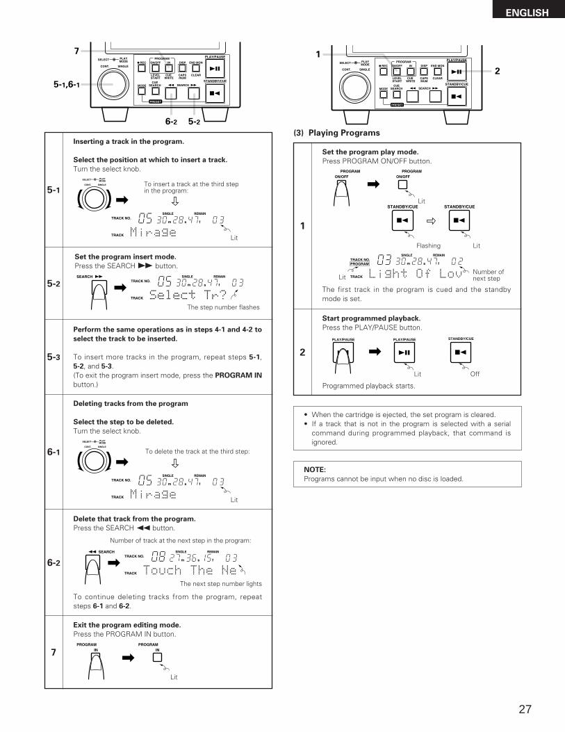
5-1
Inserting a track in the program.
Select the position at which to insert a track.
Turn the select knob.
5-2
Set the program insert mode.
Press the SEARCH 7 button.
5-3
Perform the same operations as in steps 4-1 and 4-2 to
select the track to be inserted.
To insert more tracks in the program, repeat steps 5-1,5-2, and 5-3.(To exit the program insert mode, press the PROGRAM IN
button.)
6-1
Deleting tracks from the program
Select the step to be deleted.
Turn the select knob.
Lit
To insert a track at the third stepin the program:
The step number flashes
Lit
To delete the track at the third step:
6-2
Delete that track from the program.
Press the SEARCH 6 button.
To continue deleting tracks from the program, repeatsteps 6-1 and 6-2.
7
Exit the program editing mode.
Press the PROGRAM IN button.
1
Set the program play mode.
Press PROGRAM ON/OFF button.
2
Start programmed playback.
Press the PLAY/PAUSE button.
The first track in the program is cued and the standbymode is set.
Programmed playback starts.
PLAY/PAUSE PLAY/PAUSE STANDBY/CUE
Number of track at the next step in the program:
The next step number lights
Lit
(3) Playing Programs
Number ofnext step
Lit
LitFlashing
OffLit
• When the cartridge is ejected, the set program is cleared.• If a track that is not in the program is selected with a serial
command during programmed playback, that command isignored.
NOTE:
Programs cannot be input when no disc is loaded.
Lit
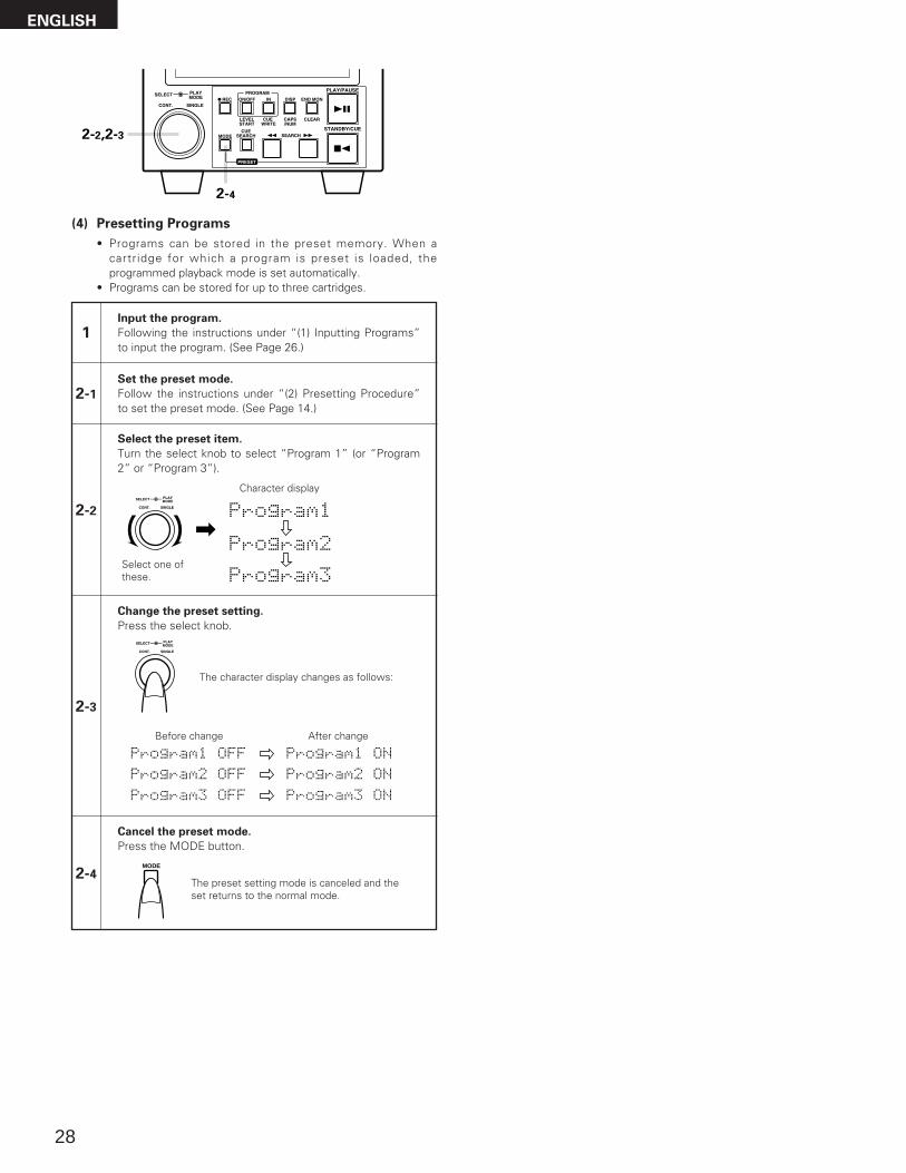
28
ENGLISH
(4) Presetting Programs
• Programs can be stored in the preset memory. When acartridge for which a program is preset is loaded, theprogrammed playback mode is set automatically.
• Programs can be stored for up to three cartridges.
1Input the program.
Following the instructions under “(1) Inputting Programs”to input the program. (See Page 26.)
2-1Set the preset mode.
Follow the instructions under “(2) Presetting Procedure”to set the preset mode. (See Page 14.)
2-2
Select the preset item.
Turn the select knob to select “Program 1” (or “Program2” or “Program 3”).
2-3
Change the preset setting.
Press the select knob.
2-4
Cancel the preset mode.
Press the MODE button.
MODE
Character display
Select one ofthese.
The character display changes as follows:
After changeBefore change
The preset setting mode is canceled and theset returns to the normal mode.
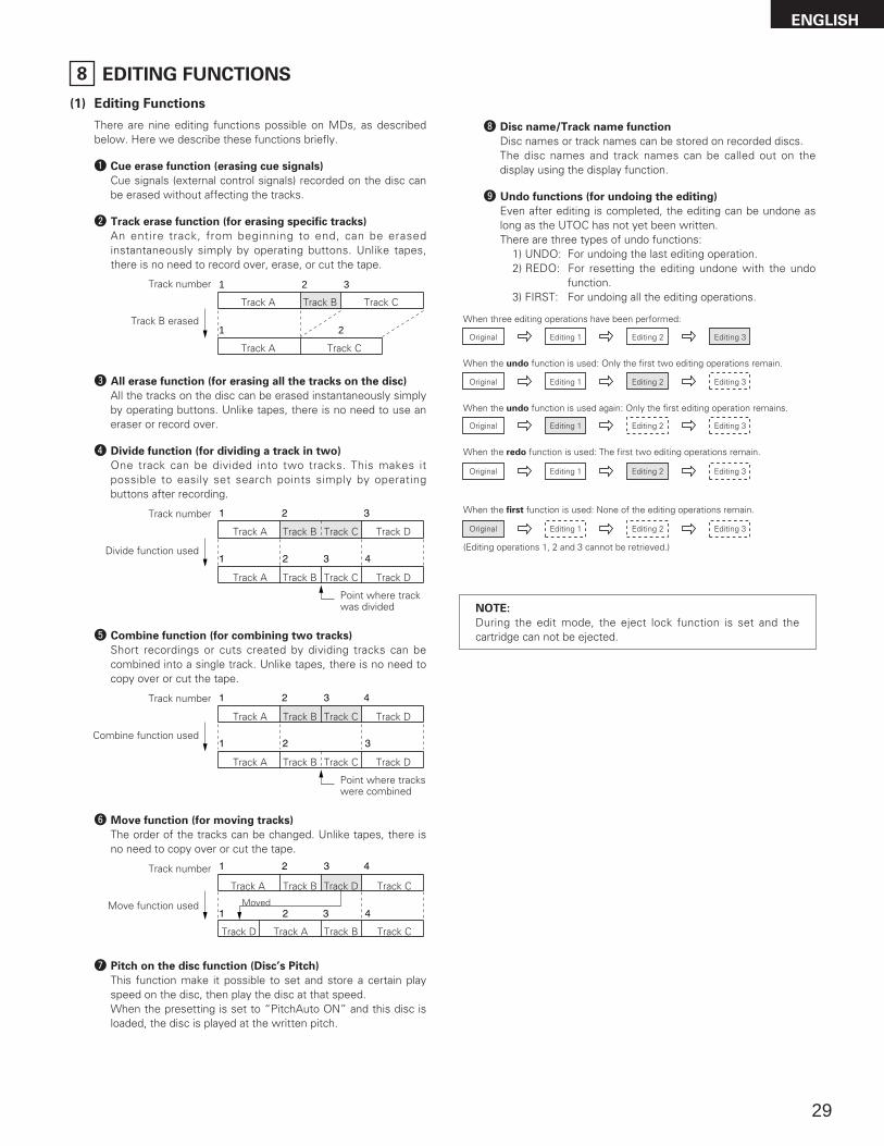
29
ENGLISH
EDITING FUNCTIONS
There are nine editing functions possible on MDs, as describedbelow. Here we describe these functions briefly.
q Cue erase function (erasing cue signals)
Cue signals (external control signals) recorded on the disc canbe erased without affecting the tracks.
w Track erase function (for erasing specific tracks)
An entire track, from beginning to end, can be erasedinstantaneously simply by operating buttons. Unlike tapes,there is no need to record over, erase, or cut the tape.
(1) Editing Functions
1 2 3
1 2Track B erased
e All erase function (for erasing all the tracks on the disc)
All the tracks on the disc can be erased instantaneously simplyby operating buttons. Unlike tapes, there is no need to use aneraser or record over.
r Divide function (for dividing a track in two)
One track can be divided into two tracks. This makes itpossible to easily set search points simply by operatingbuttons after recording.
Track A Track CTrack B
Track CTrack A
Divide function used
Point where trackwas divided
Point where trackswere combined
t Combine function (for combining two tracks)
Short recordings or cuts created by dividing tracks can becombined into a single track. Unlike tapes, there is no need tocopy over or cut the tape.
y Move function (for moving tracks)
The order of the tracks can be changed. Unlike tapes, there isno need to copy over or cut the tape.
u Pitch on the disc function (Disc’s Pitch)
This function make it possible to set and store a certain playspeed on the disc, then play the disc at that speed.When the presetting is set to “PitchAuto ON” and this disc isloaded, the disc is played at the written pitch.
Combine function used
Move function used
Track number
Track number
Track number
Track A
Track D Track A Track B Track C
Track B Track CTrack D
Moved
When three editing operations have been performed:
(Editing operations 1, 2 and 3 cannot be retrieved.)
When the undo function is used: Only the first two editing operations remain.
When the undo function is used again: Only the first editing operation remains.
When the redo function is used: The first two editing operations remain.
When the first function is used: None of the editing operations remain.
Original
Original
Original
Original
Original
Editing 1
Editing 1
Editing 1
Editing 1
Editing 1
Editing 2
Editing 2
Editing 2
Editing 2
Editing 3
Editing 3
Editing 3
Editing 3
Editing 2 Editing 3
Track number
i Disc name/Track name function
Disc names or track names can be stored on recorded discs.The disc names and track names can be called out on thedisplay using the display function.
o Undo functions (for undoing the editing)
Even after editing is completed, the editing can be undone aslong as the UTOC has not yet been written.There are three types of undo functions:
1) UNDO: For undoing the last editing operation.2) REDO: For resetting the editing undone with the undo
function.3) FIRST: For undoing all the editing operations.
NOTE:
During the edit mode, the eject lock function is set and thecartridge can not be ejected.
8
Track A
Track A
Track B
Track B
Track C
Track C
Track D
Track D
Track A
Track A
Track B
Track B
Track C
Track C
Track D
Track D
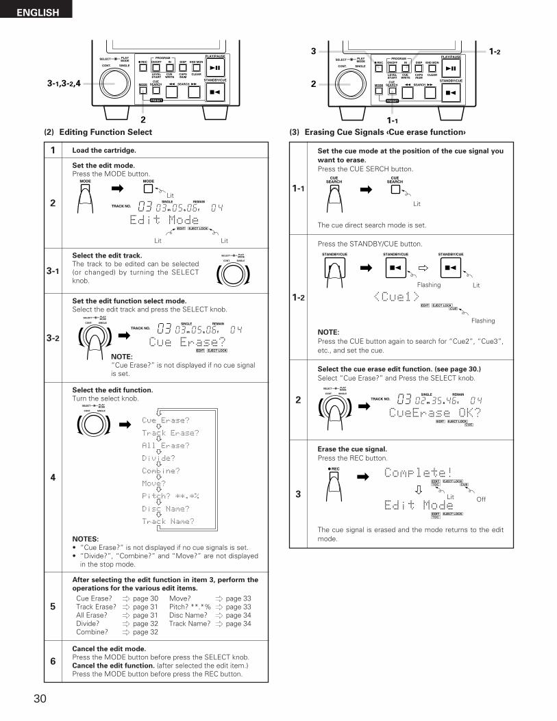
30
ENGLISH
(2) Editing Function Select
1 Load the cartridge.
2
Set the edit mode.
Press the MODE button.
4
Select the edit function.
Turn the select knob.
NOTES:
• “Cue Erase?” is not displayed if no cue signals is set.• “Divide?”, “Combine?” and “Move?” are not displayed
in the stop mode.
Lit Lit
Lit
5
After selecting the edit function in item 3, perform the
operations for the various edit items.
6
Cancel the edit mode.
Press the MODE button before press the SELECT knob.Cancel the edit function. (after selected the edit item.)Press the MODE button before press the REC button.
(3) Erasing Cue Signals ‹Cue erase function›
1-1
Set the cue mode at the position of the cue signal you
want to erase.
Press the CUE SERCH button.
The cue direct search mode is set.
1-2
Press the STANDBY/CUE button.
NOTE:
Press the CUE button again to search for “Cue2”, “Cue3”,etc., and set the cue.
Lit
LitFlashing
Flashing
2
Select the cue erase edit function. (see page 30.)
Select “Cue Erase?” and Press the SELECT knob.
3
The cue signal is erased and the mode returns to the editmode.
Lit Off
Erase the cue signal.
Press the REC button.
Cue Erase? | page 30Track Erase? | page 31All Erase? | page 31Divide? | page 32Combine? | page 32
Move? | page 33Pitch? **.*% | page 33Disc Name? | page 34Track Name? | page 34
3-2
Set the edit function select mode.
Select the edit track and press the SELECT knob.
NOTE:
“Cue Erase?” is not displayed if no cue signalis set.
3-1
Select the edit track.
The track to be edited can be selected(or changed) by turning the SELECTknob.
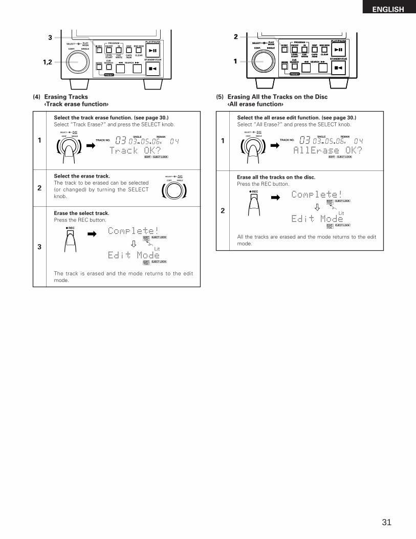
31
ENGLISH
(4) Erasing Tracks
‹Track erase function›
(5) Erasing All the Tracks on the Disc
‹All erase function›
1
Select the track erase function. (see page 30.)
Select “Track Erase?” and press the SELECT knob.
3
Erase the select track.
Press the REC button.
The track is erased and the mode returns to the editmode.
Lit
2
All the tracks are erased and the mode returns to the editmode.
Lit
2
Select the erase track.
The track to be erased can be selected(or changed) by turning the SELECTknob.
1
Select the all erase edit function. (see page 30.)
Select “All Erase?” and press the SELECT knob.
Erase all the tracks on the disc.
Press the REC button.
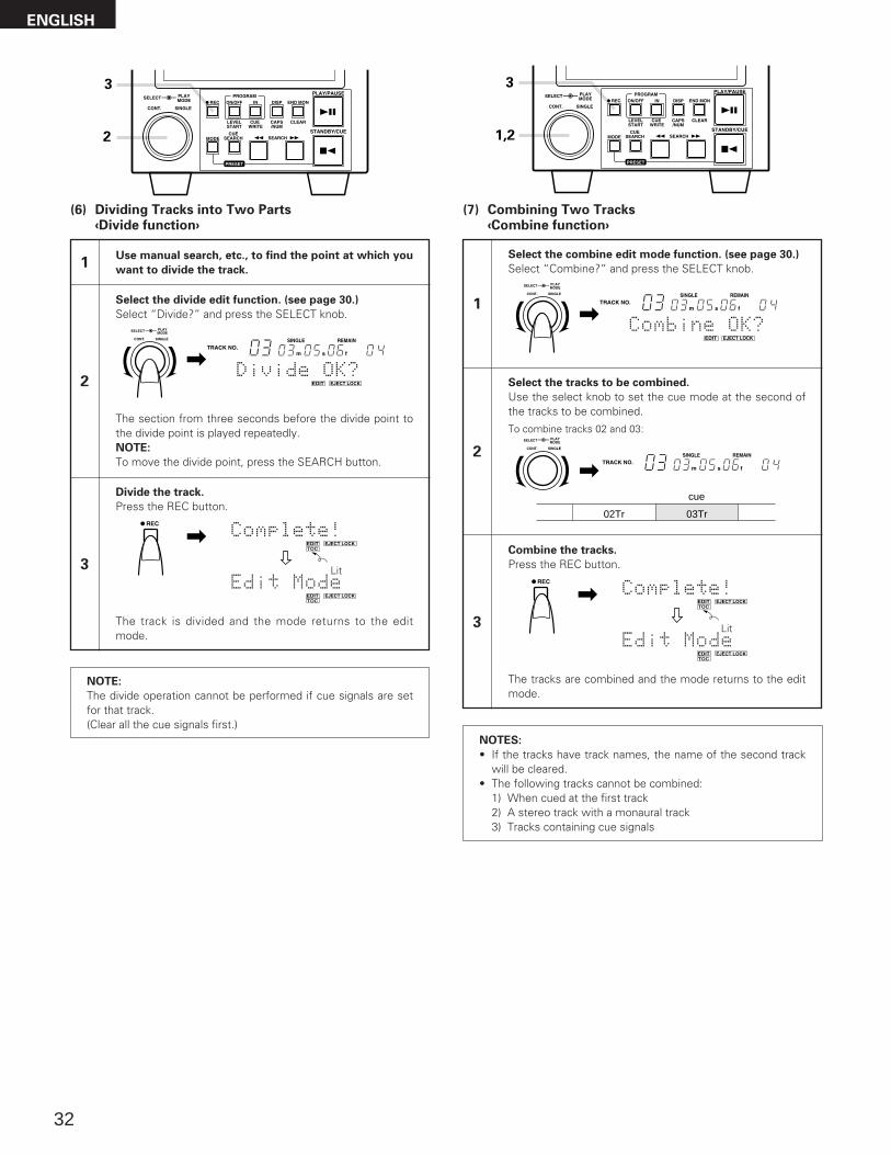
32
ENGLISH
(7) Combining Two Tracks
‹Combine function›
2
Select the tracks to be combined.
Use the select knob to set the cue mode at the second ofthe tracks to be combined.
03Tr02Tr
cue
1
Select the combine edit mode function. (see page 30.)
Select “Combine?” and press the SELECT knob.
3
Combine the tracks.
Press the REC button.
The tracks are combined and the mode returns to the editmode.
To combine tracks 02 and 03:
NOTES:
• If the tracks have track names, the name of the second trackwill be cleared.
• The following tracks cannot be combined:1) When cued at the first track2) A stereo track with a monaural track3) Tracks containing cue signals
Lit
(6) Dividing Tracks into Two Parts
‹Divide function›
1Use manual search, etc., to find the point at which you
want to divide the track.
The section from three seconds before the divide point tothe divide point is played repeatedly.NOTE:
To move the divide point, press the SEARCH button.
3
Divide the track.
Press the REC button.
The track is divided and the mode returns to the editmode.
Lit
NOTE:
The divide operation cannot be performed if cue signals are setfor that track.(Clear all the cue signals first.)
2
Select the divide edit function. (see page 30.)
Select “Divide?” and press the SELECT knob.
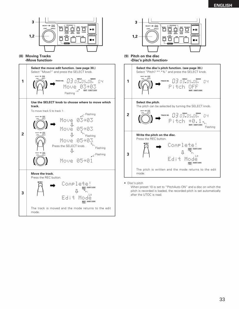
33
ENGLISH
(9) Pitch on the disc
‹Disc’s pitch function›
2
Select the pitch.
The pitch can be selected by turning the SELECT knob.
1
Select the disc’s pitch function. (see page 30.)
Select “Pitch? **.*%” and press the SELECT knob.
3
Write the pitch on the disc.
Press the REC button.
The pitch is written and the mode returns to the editmode.
Lit
Flashing
(8) Moving Tracks
‹Move function›
1
Select the move edit function. (see page 30.)
Select “Move?” and press the SELECT knob.
2
Use the SELECT knob to choose where to move which
track.
3
Move the track.
Press the REC button.
The track is moved and the mode returns to the editmode.
To move track 5 to track 1:
Lit
Flashing
Flashing
Flashing
Flashing
Flashing
Press the SELECT knob.
• Disc’s pitchWhen preset 10 is set to “PitchAuto ON” and a disc on which thepitch is recorded is loaded, the recorded pitch is set automaticallyafter the UTOC is read.
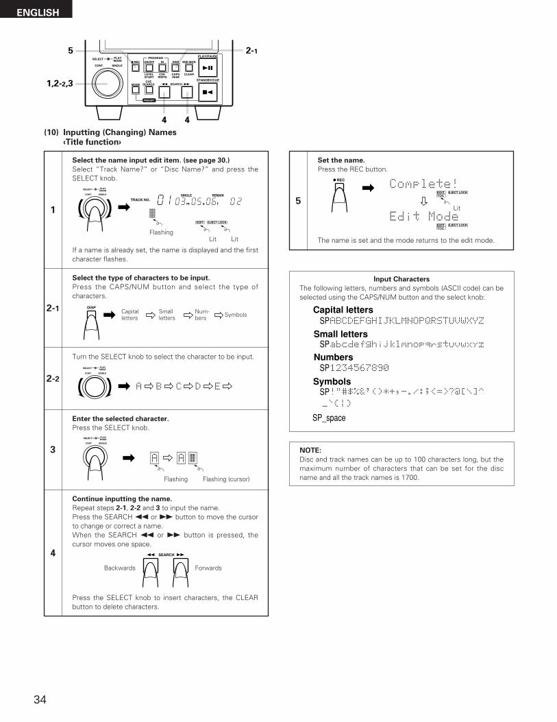
34
ENGLISH
(10) Inputting (Changing) Names
‹Title function›
1
Select the name input edit item. (see page 30.)
Select “Track Name?” or “Disc Name?” and press theSELECT knob.
If a name is already set, the name is displayed and the firstcharacter flashes.
2-1
Select the type of characters to be input.
Press the CAPS/NUM button and select the type ofcharacters.
2-2
Turn the SELECT knob to select the character to be input.
CAPS/NUM
DISP
3
Enter the selected character.
Press the SELECT knob.
LitFlashing
Capital letters
Small letters
Num-bers Symbols
Flashing (cursor)Flashing
4
Continue inputting the name.
Repeat steps 2-1, 2-2 and 3 to input the name.Press the SEARCH 6 or 7 button to move the cursorto change or correct a name.When the SEARCH 6 or 7 button is pressed, thecursor moves one space.
5
Set the name.
Press the REC button.
The name is set and the mode returns to the edit mode.
Forwards
NOTE:
Disc and track names can be up to 100 characters long, but themaximum number of characters that can be set for the discname and all the track names is 1700.
Input Characters
The following letters, numbers and symbols (ASCII code) can beselected using the CAPS/NUM button and the select knob:
Backwards
Lit
Lit
Press the SELECT knob to insert characters, the CLEARbutton to delete characters.
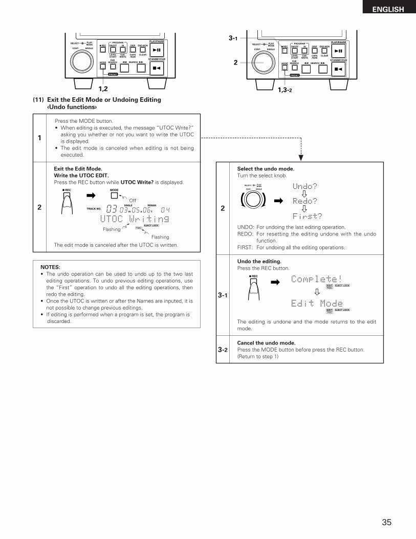
35
ENGLISH
(11) Exit the Edit Mode or Undoing Editing
‹Undo functions›
1
Press the MODE button.• When editing is executed, the message “UTOC Write?”
asking you whether or not you want to write the UTOCis displayed.
• The edit mode is canceled when editing is not beingexecuted.
2
Select the undo mode.
Turn the select knob.
UNDO: For undoing the last editing operation.REDO: For resetting the editing undone with the undo
function.FIRST: For undoing all the editing operations.
3-1
Undo the editing.
Press the REC button.
3-2Cancel the undo mode.
Press the MODE button before press the REC button.(Return to step 1)
The editing is undone and the mode returns to the editmode.
NOTES:
• The undo operation can be used to undo up to the two lastediting operations. To undo previous editing operations, usethe “First” operation to undo all the editing operations, thenredo the editing.
• Once the UTOC is written or after the Names are inputed, it isnot possible to change previous editings.
• If editing is performed when a program is set, the program isdiscarded.
2
Exit the Edit Mode.
Write the UTOC EDIT.
Press the REC button while UTOC Write? is displayed.
Flashing
Flashing
The edit mode is canceled after the UTOC is written.
ª
Off
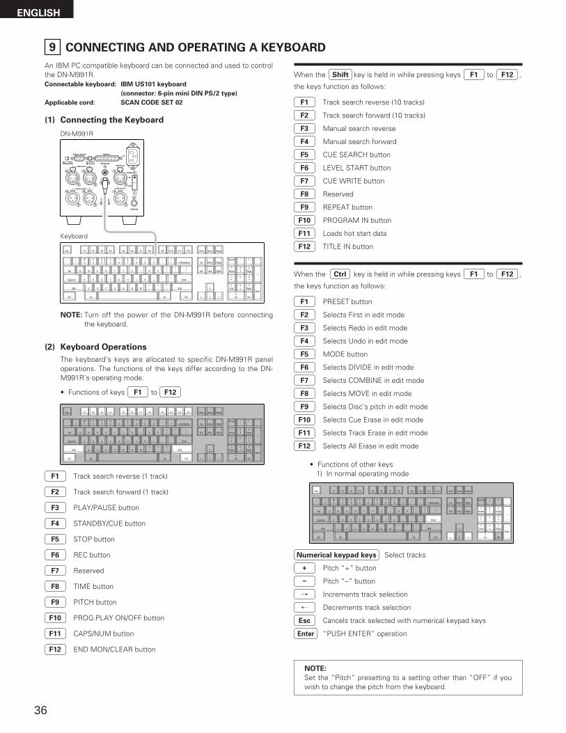
36
ENGLISH
• Functions of keys to
CONNECTING AND OPERATING A KEYBOARD
NOTE: Turn off the power of the DN-M991R before connectingthe keyboard.
(1) Connecting the Keyboard
(2) Keyboard Operations
An IBM PC compatible keyboard can be connected and used to controlthe DN-M991R.Connectable keyboard: IBM US101 keyboard
(connector: 6-pin mini DIN PS/2 type)
Applicable cord: SCAN CODE SET 02
The keyboard’s keys are allocated to specific DN-M991R paneloperations. The functions of the keys differ according to the DN-M991R’s operating mode.
F1
F2
F3
F4
F5
F6
F7
F8
F9
F10
F11
F12
F1 F12
Esc
Tab
Ctrl
1 2 3 4 5 6 7 8 9 0 =_ ! @ # $ % ^ & ( ) _ +
Q W E R T Y U I O P [ ]
/
Ctrl
|
A S D F G H J K L ; `: "
Z
Alt
Capslock
Shift X C V B N M , . /
Alt
< > ?Shift
Enter
Backspace
F1 F2 F3 F4 F5 F6 F7 F8 F9 F10 F11 F12 Print Scrol Pause
Ins Home PgUpNumLk / -
Home PgUp+
End PgDn
7 8 9
4 5 6
1 2 3
Enter
Ins0
Del
Del End PgDn
Track search reverse (1 track)
Track search forward (1 track)
PLAY/PAUSE button
STANDBY/CUE button
STOP button
REC button
Reserved
TIME button
PITCH button
PROG.PLAY ON/OFF button
CAPS/NUM button
END MON/CLEAR button
F1
F2
F3
F4
F5
F6
F7
F8
F9
F10
F11
F12
When the key is held in while pressing keys to ,
the keys function as follows:
When the key is held in while pressing keys to ,
the keys function as follows:
Shift F12F1
F12F1
Track search reverse (10 tracks)
Track search forward (10 tracks)
Manual search reverse
Manual search forward
CUE SEARCH button
LEVEL START button
CUE WRITE button
Reserved
REPEAT button
PROGRAM IN button
Loads hot start data
TITLE IN button
F1
F2
F3
F4
F5
F6
F7
Numerical keypad keys Select tracks
+
–
/
,
Esc
Enter
F8
F9
F10
F11
F12
PRESET button
Selects First in edit mode
Selects Redo in edit mode
Selects Undo in edit mode
MODE button
Selects DIVIDE in edit mode
Selects COMBINE in edit mode
Selects MOVE in edit mode
Selects Disc’s pitch in edit mode
Selects Cue Erase in edit mode
Selects Track Erase in edit mode
Selects All Erase in edit mode
• Functions of other keys1) In normal operating mode
Esc
Tab
Ctrl
1 2 3 4 5 6 7 8 9 0 =_ ! @ # $ % ^ & ( ) _ +
Q W E R T Y U I O P [ ]
/
Ctrl
|
A S D F G H J K L ; `: "
Z
Alt
Capslock
Shift X C V B N M , . /
Alt
< > ?Shift
Enter
Backspace
F1 F2 F3 F4 F5 F6 F7 F8 F9 F10 F11 F12 Print Scrol Pause
Ins Home PgUpNumLk / -
Home PgUp+
End PgDn
7 8 9
4 5 6
1 2 3
Enter
Ins0
Del
Del End PgDn
Pitch “+” button
Pitch “–” button
Increments track selection
Decrements track selection
Cancels track selected with numerical keypad keys
“PUSH ENTER” operation
Ctrl
NOTE:
Set the “Pitch” presetting to a setting other than “OFF” if youwish to change the pitch from the keyboard.
9
DN-M991R
Keyboard
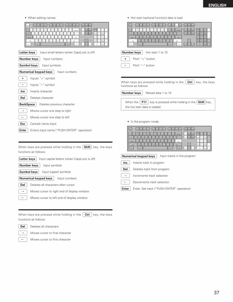
37
ENGLISH
• When editing names
Esc
Tab
Ctrl
1 2 3 4 5 6 7 8 9 0 =_ ! @ # $ % ^ & ( ) _ +
Q W E R T Y U I O P [ ]
/
Ctrl
|
A S D F G H J K L ; `: "
Z
Alt
Capslock
Shift X C V B N M , . /
Alt
< > ?Shift
Enter
Backspace
F1 F2 F3 F4 F5 F6 F7 F8 F9 F10 F11 F12 Print Scrol Pause
Ins Home PgUpNumLk / -
Home PgUp+
End PgDn
7 8 9
4 5 6
1 2 3
Enter
Ins0
Del
Del End PgDn
• Hot start (optional function) data is load
• In the program mode
Esc
Tab
Ctrl
1 2 3 4 5 6 7 8 9 0 =_ ! @ # $ % ^ & ( ) _ +
Q W E R T Y U I O P [ ]
/
Ctrl
|
A S D F G H J K L ; `: "
Z
Alt
Capslock
Shift X C V B N M , . /
Alt
< > ?Shift
Enter
Backspace
F1 F2 F3 F4 F5 F6 F7 F8 F9 F10 F11 F12 Print Scrol Pause
Ins Home PgUpNumLk / -
Home PgUp+
End PgDn
7 8 9
4 5 6
1 2 3
Enter
Ins0
Del
Del End PgDn
Letter keys Input small letters (when CapsLock is off)
Input numbers
Input symbols
Input numbers
Inputs “+” symbol
Inputs “–” symbol
Inserts character
Deletes character
Deletes previous character
Moves cursor one step to right
Moves cursor one step to left
Cancels name input
Enters input name (“PUSH ENTER” operation)
+
–
Pitch “+” button
Pitch “–” button
+
–
Inserts track in program
Deletes track from program
Increments track selection
Decrements track selection
Enter: Set track (“PUSH ENTER” operation)
Ins
Del
Enter
/
,
Ins
Del
Del
BackSpace
/
,
/
,
Esc
Enter
Number keys
Hot start 1 to 10Number keys
Reload data 1 to 10Number keys
Symbol keys
Numerical keypad keys
Letter keys
Number keys
Symbol keys
Numerical keypad keys Input numbers
When keys are pressed while holding in the key, the keys
functions as follows:
Shift
When keys are pressed while holding in the key, the keys
functions as follows:
Input capital letters (when CapsLock is off)
Input symbols
Input (upper) symbols
Deletes all characters after cursor
Moves cursor to right end of display window
Moves cursor to left end of display window
Del
/
,
Deletes all characters
Moves cursor to final character
Moves cursor to first character
When the key is pressed while holding in the key,
the hot start data is loaded.
ShiftF11
Esc
Tab
Ctrl
1 2 3 4 5 6 7 8 9 0 =_ ! @ # $ % ^ & ( ) _ +
Q W E R T Y U I O P [ ]
/
Ctrl
|
A S D F G H J K L ; `: "
Z
Alt
Capslock
Shift X C V B N M , . /
Alt
< > ?Shift
Enter
Backspace
F1 F2 F3 F4 F5 F6 F7 F8 F9 F10 F11 F12 Print Scrol Pause
Ins Home PgUpNumLk / -
Home PgUp+
End PgDn
7 8 9
4 5 6
1 2 3
Enter
Ins0
Del
Del End PgDn
Input tracks in the programNumerical keypad keys
Ctrl
When keys are pressed while holding in the key, the keysfunctions as follows:
Ctrl
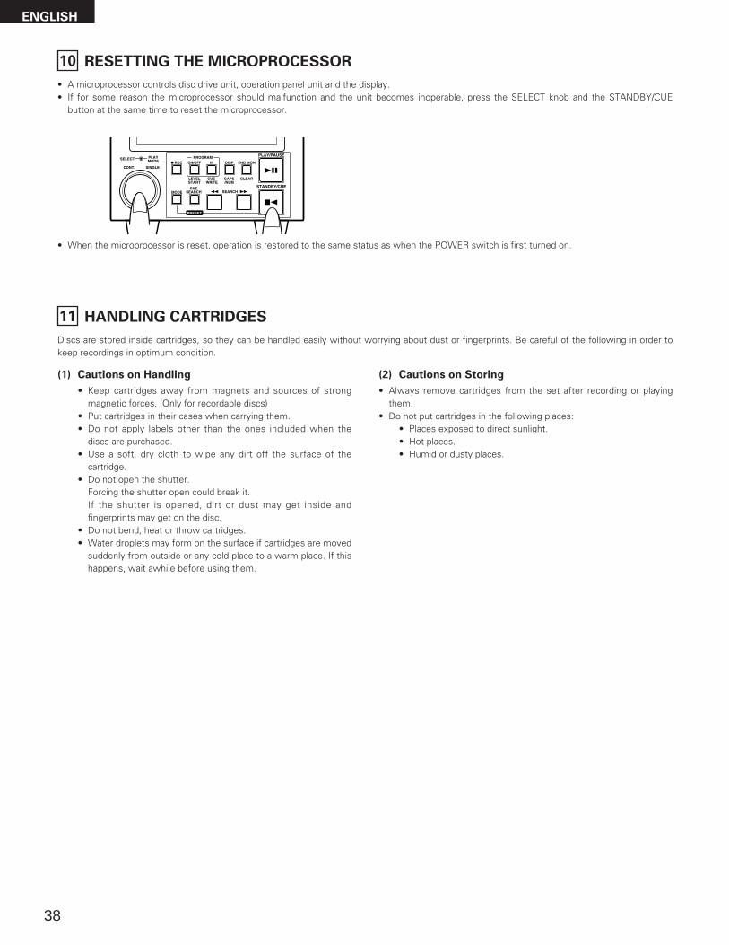
38
ENGLISH
RESETTING THE MICROPROCESSOR
HANDLING CARTRIDGES
Discs are stored inside cartridges, so they can be handled easily without worrying about dust or fingerprints. Be careful of the following in order tokeep recordings in optimum condition.
• Keep cartridges away from magnets and sources of strongmagnetic forces. (Only for recordable discs)
• Put cartridges in their cases when carrying them.• Do not apply labels other than the ones included when the
discs are purchased.• Use a soft, dry cloth to wipe any dirt off the surface of the
cartridge.• Do not open the shutter.
Forcing the shutter open could break it.If the shutter is opened, dirt or dust may get inside andfingerprints may get on the disc.
• Do not bend, heat or throw cartridges.• Water droplets may form on the surface if cartridges are moved
suddenly from outside or any cold place to a warm place. If thishappens, wait awhile before using them.
(1) Cautions on Handling (2) Cautions on Storing
• Always remove cartridges from the set after recording or playingthem.
• Do not put cartridges in the following places:• Places exposed to direct sunlight.• Hot places.• Humid or dusty places.
11
• A microprocessor controls disc drive unit, operation panel unit and the display.• If for some reason the microprocessor should malfunction and the unit becomes inoperable, press the SELECT knob and the STANDBY/CUE
button at the same time to reset the microprocessor.
• When the microprocessor is reset, operation is restored to the same status as when the POWER switch is first turned on.
10
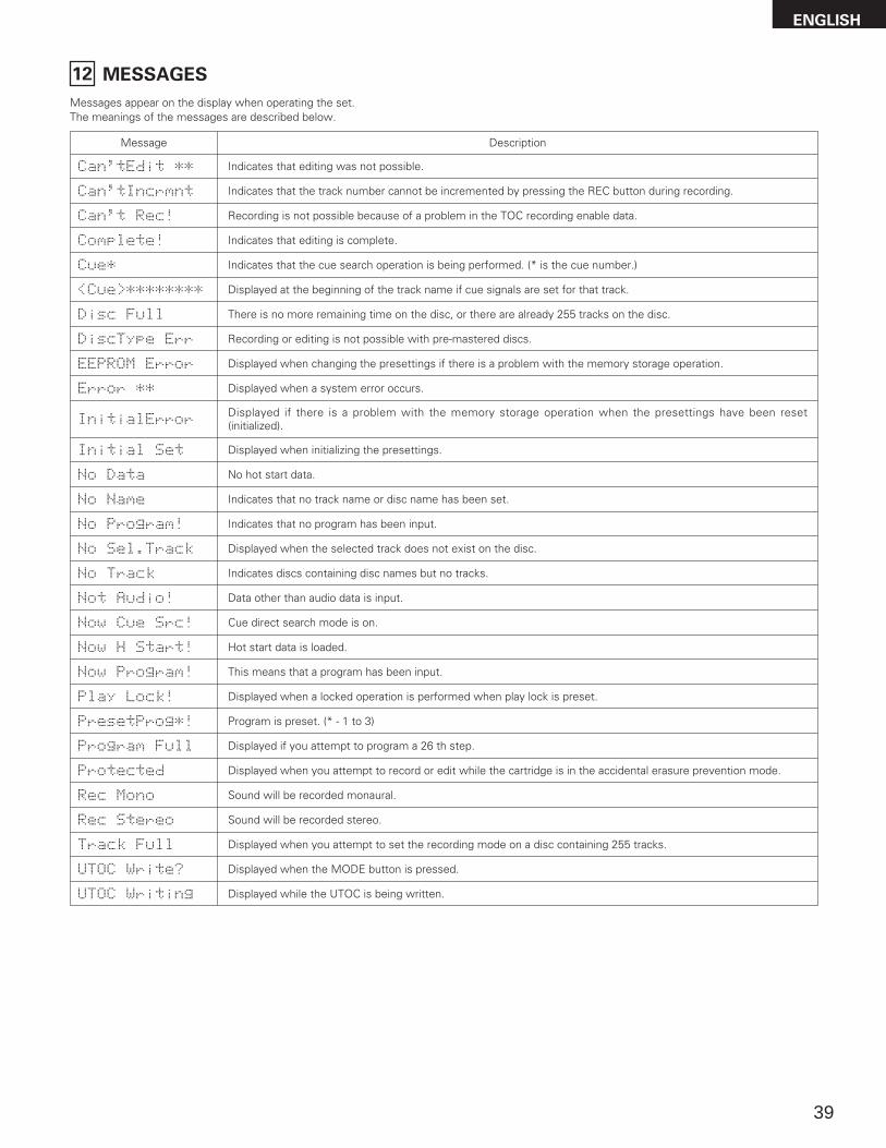
39
ENGLISH
MESSAGES
Messages appear on the display when operating the set.The meanings of the messages are described below.
Message Description
Indicates that editing was not possible.
Indicates that the track number cannot be incremented by pressing the REC button during recording.
Recording is not possible because of a problem in the TOC recording enable data.
Indicates that editing is complete.
Indicates that the cue search operation is being performed. (* is the cue number.)
Displayed at the beginning of the track name if cue signals are set for that track.
There is no more remaining time on the disc, or there are already 255 tracks on the disc.
Recording or editing is not possible with pre-mastered discs.
Displayed when changing the presettings if there is a problem with the memory storage operation.
Displayed when a system error occurs.
Displayed if there is a problem with the memory storage operation when the presettings have been reset(initialized).
Displayed when initializing the presettings.
No hot start data.
Indicates that no track name or disc name has been set.
Indicates that no program has been input.
Indicates discs containing disc names but no tracks.
Data other than audio data is input.
Cue direct search mode is on.
Hot start data is loaded.
This means that a program has been input.
Program is preset. (* - 1 to 3)
Displayed if you attempt to program a 26 th step.
Displayed when you attempt to record or edit while the cartridge is in the accidental erasure prevention mode.
Sound will be recorded stereo.
Displayed when you attempt to set the recording mode on a disc containing 255 tracks.
Displayed when the MODE button is pressed.
12
Can,tEdit **
Can,tIncrmnt
Can,t Rec!
Complete!
Cue*
<Cue>********
Disc Full
DiscType Err
EEPROM Error
Error **
InitialError
Initial Set
No Data
No Name
No Program!
No Track
Not Audio!
Now Cue Src!
Now H Start!
Now Program!
Displayed when a locked operation is performed when play lock is preset.Play Lock!
PresetProg*!
Program Full
Protected
Rec Stereo
Track Full
UTOC Write?
Displayed when the selected track does not exist on the disc.No Sel.Track
Sound will be recorded monaural.Rec Mono
Displayed while the UTOC is being written.UTOC Writing
40
ENGLISH
SYSTEM LIMITATIONS
(1) Track Number Limits
• Up to 255 tracks can be recorded when recording the trackssuccessively starting from the first track on blank or no-trackdiscs. In the following cases, however, the number of tracksthat can be recorded decreases:
When editing has been performed.When there are scratches on the disc and tracks have beenre-recorded.
(5) Other Limits
• In the program play mode, the record mode is not set evenwhen the REC button is pressed.If the REC button is pressed, “Now Program!” is displayed forapproximately 1 second, then turns off.
• In the program play mode, the editing mode is not set evenwhen the MODE button is pressed.If the MODE button is pressed, “Now Program!” is displayedfor approximately 1 second, then turns off.
• In the editing mode and during hot start loading, the programplay mode is not set even when the PROGRAM ON/OFFbutton is pressed.
• If the REC button is pressed while hot start data is loaded,“Now H Start!” is displayed for 5 seconds. If the REC button ispressed while “Now H Start!” is displayed, the recording pausemode is set. (The hot start data is cleared.)
(2) Recording Time Limits
• Recording is performed in units of approximately 2 seconds.Sections of less than 2 seconds still take up 2 seconds worth ofspace on the disc, so this decreases the actual recordable time.
• Scratched sections of discs are automatically eliminated fromthe recording time.
• Recording is no longer possible once the maximum number oftracks is reached, even if they take up less than the maximumrecordable time. To record on such discs, first erase unneededtracks. When this is done, it is not possible to record for longerthan the time of the tracks that have been erased.
• The remaining time on the disc may not increase when shorttracks (less than approximately 8 seconds) are erased.
• If there are many emphasis data on/off signals or other similarsignals in a track, they are treated as divisions between tracks,so recording will not be possible regardless of the recordingtime and number of tracks.
• Track incrementing may not be possible if it is conducted(automatically or manually) consecutively within less than 2seconds.
(3) Editing Function Limits
• It may not be possible to combine a short track with anothertrack.
• Tracks containing cue points cannot be divided or combined.
(4) Title Function Limits
• There are limits to the number of characters that can be used indisc and track names and to the total number of charactersused for both. When writing names, the cursor will only moveby the maximum number of writeable spaces. (after this nomore characters can be input.)
Track names: Up to 100 charactersDisc names: Up to 100 charactersTotal: Up to 1700 characters
• The number of characters that can be used in track namesdecreases when the following functions are used:
Cue point function: Using one point decreases thenumber of characters that can beused by 10.
Play speed function: Changing the play speed decreasesthe number of characters that can beused by 6.
13
CAUTION:
Because cue points are stored on the disc as name inputs, itmay not be possible to input names if many cue points are seton discs with many tracks, and if many names are used it maynot be possible to store cue points.
• When a track with a track name is divided, both of the dividedtracks are given the same name. However, if the number ofcharacters writeable on the disc is near the limit, the secondtrack may only have part of the track name.
• When two tracks with track names are combined, the name ofthe second track is erased.
41
ENGLISH
SPECIFICATIONS
GENERAL
Type: MiniDisc RecorderRecordable/Playable Discs: Playback: Pre-mastered MDs and recordable MDs
Recording: Recordable MDsRecording System: Magneto-optical overwriting system (Magnetic field modulation)Signal Compression System: ATRAC (Adaptive Transform Acoustic Coding) version 4.0Rotating Speed: Approx. 400 to 900 rpm.Recording/playback time: 74 min. (Stereo), 148 min. (Mono)
AUDIO SECTION
Channels: 2 channels (Stereo), 1 channel (Mono)Sampling Frequency: 44.1 kHzQuantization Bits: A/D converter: 16 bit, D/A converter: 18 bitFrequency Response: 20 to 20,000 Hz (±1.0 dB)Total Harmonic Distortion: 0.015 % or less (Playback, A filter)
0.035 % or less (Recording, A filter)Signal to Noise Ratio: 100 dB or higher (Playback, A filter)
84 dB or higher (Recording, A filter)Channel Separation: 90 dB or higher (Playback, A filter)
80 dB or higher (Recording, A filter)Analog Output: (1 kHz, 0 dB playback)
Connector: XLR connectorOutput Level: +18 dBs, 600 Ω/ohmsMonitor Output: 20 mW or greater (30 to 40 Ω/ohms)
Analog Input:
Connector: XLR connectorInput Level: +18 dBs, 10 kΩ/kohms
Digital Output:
Connector: XLR connectorSignal Format: AES/EBU or IEC-958 Type IOutput Level: 3 Vp-p or greater, 110 Ω/ohms
Digital Input:
Connector: XLR connectorSignal Format: AES/EBU or IEC-958 Type IInput Level: 3 to 10 Vp-p, 110 Ω/ohms
Variable Pitch Control: ±8 %Audio Start-up Time: 0.03 second lessFrame Search Accuracy: 1 frame (1/86 second)
DIMENSIONS
Without feet: 144 (W) x 133 (H) x 401 (D)(5-43/64” x 5-15/64” x 15-25/32”)
With feet: 144 (W) x 146 (H) x 401 (D)(5-43/64” x 5-3/4” x 15-25/32”)(Not including feet, dials and terminals)
WEIGHT
Recorder unit: 5.0 kg (11.02 lbs)
POWER CONSUMPTION: 22 W
POWER SUPPLY: AC 120 V ±10 %, 60 Hz (U.S.A. & Canada)AC 230 V ±10 %, 50 Hz (Europe, Asia & Others)
ENVIRONMENTAL CONDITIONS
Operating Temperature: +5 °C to 35 °CHumidity: 25 % to 85 %, non condensingStorage Temperature: –20 °C to 60 °C
* Specifications and design are subject to change without notice for purpose improvement.
US and foreign patents licensed from Dolby laboratories Licensing Corporation.
14