Embed Size (px)
Citation preview

Page 1 of 88 pagesVersion 1.0 ProMinent Dosiertechnik GmbH • D-69123 Heidelberg • F.R. Germany
BA G5 004 5/98 GB • Part No. 981313
Please first read the operating instructions from cover to cover! • Do not throw them away!The warranty does not cover damages due to faulty operation!
®
Operating InstructionsMetering PumpProMinent® gamma G/5b
Affix type identification plate here!
10
20
30
40
5060
7080
90
100
STOPSTOPSTARTSTART
P
gamma/5
G/5b-001-D

Device Overview/Control Elements
10
20
30
40
5060
7080
90
100
STOPSTOPSTARTSTART
P
gamma/5
4
STOP
STOPSTART
START
P
gamma/5
10
20
30
4050
60
70
80
90
100
321 8765
910111213
1514
16 17 / 17a / 17b
18192122 20G/5b-002-D

➠Always unfold the page first!

Page 2 of 88 pages Version 1.0
Kapitel
fffbbbbbb
Explanation of Devices and Operating Parts
More detailed informationon pages:
1 Pulse/pilot light (yellow) ................................................................. 51, 75, 81
2 Down key ...............................................................................................51 ff.
3 Stroke length adjustment knob .................................................................. –
4 LCD display field....................................................................................... 50
5 Program selection key .......................................................................... 51 ff.
6 Up key .................................................................................................. 51 ff.
7 Stop/start key........................................................................................ 51 ff.
8 Display light for empty display and fault annunciation (red) .......... 51, 56, 76
9 Connection thread PG-9 for relay output (with blank plug)...................... 51
10 Connection socket metering monitor ...................................... 32, 35, 51, 58
11 Connection socket for float switch (with function plug) 32, 35, 51, 54, 57, 59
12 On/off control (with function plug) ...................................... 32, 35, 51, 54, 58
13 Mains supply............................................................................................ 32
14 View window .............................................................................................. –
15 Enclosure................................................................................................... –
16 Pressure valve ............................................................................... 23, 27-31
19 Liquid end ........................................................................................... 76-80
20 Intermediate disk with leakage bore ................................................... 76-80
21 Suction valve ................................................................................. 23,27-31
22 Short operating instructions ....................................................................... –
Only for PP and NP version:
17 Bleed valve ...................................................................................... 25, 36 ff
17 a Fine bleed valve ............................................................................... 25,36 ff
17 b Star handle ....................................................................................... 25,36 ff
18 Bypass tube nozzle ................................................................................. 25

Page 3 of 88 pagesVersion 1.0
Imprint:
Operating Instructions gamma 5 metering Pump© ProMinent Dosiertechnik GmbH, 1993
ProMinent Dosiertechnik GmbHIm Schuhmachergewann 5-11D-69123 Heidelberg, GermanyP.O. box 101760D-69007 Heidelberg, [email protected]
Subject to alterations
Technical documentation:Bartha DocuteamD-64283 Darmstadt
Issue 05/98, version 1.0
Printed in Germany

Page 4 of 88 pages Version 1.0
Contents
Page
i General notes for users .......................................................... 7
1 Introduction ............................................................................... 8
2 Functions .................................................................................. 8
2.1 Functional principle .......................................................... 8
2.2 Functions ......................................................................... 9
2.2.1 The mechanics ..................................................... 9
2.2.2 The setting range................................................ 10
2.2.3 Options ............................................................... 11
3 Technical data ........................................................................ 13
4 Installation dimensions ............................................................ 15
5 Conformity declaration ............................................................ 16
6 Accessories ............................................................................ 17
6.1 Float switch................................................................... 176.2 Control cables ............................................................... 176.3 Foot valves ................................................................... 176.4 Injection valves ............................................................. 176.5 Injection lances ............................................................. 176.6 Back-pressure valves / multifunction valves .................. 176.7 Accumulators ................................................................ 176.8 Metering monitors ......................................................... 176.9 Suction lances .............................................................. 176.10 Supply tanks ................................................................. 176.11 Manual/electric stirrers .................................................. 186.12 Console ........................................................................ 18
7 SAFETY INSTRUCTIONS ...................................................... 18
8 Order specifications ................................................................ 19
9 Unpacking ............................................................................... 20
10 Installation............................................................................... 22
10.1 Installing the pump: mechanical part .............................. 22
10.1.1 Pump installation with console or tank............... 22
10.1.2 Connection of suction/discharge line to the pump ... 22
10.1.3 Installation suction line (general instructions) .... 24
10.1.4 Installation discharge line (general information) . 25
10.1.5 Installation bybass bleed line ............................ 25
10.1.6 Installation examples ........................................ 26
Correct installation: .......................................... 27
Incorrect installation: ........................................ 31
Page 5 of 88 pagesVersion 1.0
Contents
Page
10.2 Installation pump: electrical part ..................................... 32
10.2.1 Electrical connection (general instructions) ...... 32
10.2.2 Operating modes ............................................. 33
10.2.3. Functions superior to the operating modes ...... 33
10.2.4 Parallel connection .......................................... 34
10.2.5 Wiring diagram ................................................ 35
11 Commissioning ....................................................................... 36
11.1 General instructions ..................................................... 36
11.2 Operating conditions .................................................... 36
11.3 Suction capacity/bleeding ............................................ 37
11.4 Metering accuracy ....................................................... 38
11.5 Determining the capacity by means of nomograms ...... 39
11.5.1 General information ........................................ 39
11.5.2 Nomogram 1602 ............................................. 41
11.5.3 Nomogram 1605 ............................................. 42
11.5.4 Nomogram 1006 ............................................. 43
11.5.5 Nomogram 1310 ............................................. 44
11.5.6 Nomogram 0613 ............................................. 45
11.5.7 Nomogram 0813 ............................................. 46
11.5.8 Nomogram 0417 ............................................. 47
11.5.9 Nomogram 0423 ............................................. 48
11.5.10 Nomogram 0230 ............................................. 49
12 Operation ................................................................................ 50
12.1 Explanation of the operating and display elements ......... 50
12.1.1 Display............................................................. 50
12.1.2 Control panel: keys and display lamps ............. 51
12.1.3 Multiple connector strip. Symbols and connections 51
12.2 Overview operating diagram .......................................... 52
12.3 Operating functions basic version .................................. 53
12.3.1 Starting the pump ............................................ 53
12.3.2 Stopping the metering ...................................... 53
12.3.3 Internal "Manual" operation .............................. 54
12.3.4 External "Contact" operation ............................ 55
12.3.5 Connecting a float switch ................................. 56
12.3.6 Remote on/off control (control function "Pause") .... 58
12.3.7 Metering monitor "flow" .................................... 58
12.3.8 Error messages -acknowledging error messages ....................... 59

Page 6 of 88 pages Version 1.0
Contents
Page
12.4 Overview operating scheme (option version) ................. 60
12.5 Operation (option version).............................................. 62
12.5.1 Analog control.................................................... 62
12.5.2 Pulse control ...................................................... 66
Pulse step-down/step-up "f", "N↔" or "N" .......... 69
Selection of the display functions
12.5.3 Preselection operation and memory ................... 71
Preselection operation ....................................... 71
Memory operation "Mem" .................................. 71
12.5.4 Relay option ...................................................... 72
Switching mode no. 1:"Fault annunciation relay de-energising" ............ 72Switching mode no. 2:"Pacing relay energising" ................................... 72Switching mode no. 3:"Fault annunciation relay energising" ................. 72Switching mode no. 4:"Timer relay energising" ..................................... 72
13 Maintenance ........................................................................... 74
14 Trouble shooting/eliminating errors ......................................... 74
14.1 Errors you can eliminate yourself ................................... 74
14.1.1 Pump does not prime in spite of full strokemovement and bleeding .................................... 75
14.1.2 Float switch does not switch the metering
pump off at minimum chemical level .................. 75
14.1.3 Pump does not meter although yellow displaylamp (1) flashes ................................................. 75
14.1.4 Red warning lamp (8) lights up - "Error"readout on display (4) flashes ............................ 76
14.1.5 Fluid is leaking at the intermediate disk .............. 77
14.1.6 Exchanging the complete liquid end ................... 80
14.2 Errors which require customer service assistance .......... 80
14.2.1 Pump does not move,yellow display light (1) does not light up,no readout on the display (4). ............................ 81
14.2.2 Mains connection line (system cable) damaged . 81
15 Repair ..................................................................................... 82
16 Disposal of old parts............................................................. 83
Appendix/cross section of pump ................................................ 84
Warranty application .................................................................... 85
Safety certificate ........................................................................... 87

Page 7 of 88 pagesVersion 1.0
i General notes for usersThese operating instructions describe the technical data and functioningof the G/5a metering pump, provide comprehensive safety instructionsand are arranged in clear operational steps, as explained in the followingexamples.
Equipment descriptions are indicated by normal text:
Analogue signals such as current signals 0/4 - 20 mA or voltage signalsadjustable from 0 - 60 mV, 0 - 1 V and 0 - 10 V can be used for directproportional control of the stroking rate.
Operations/activities to be performed are shown by bullets:
• Press in dowel and screw in the screw so far until the screw head stillprojects 3.5 to 4 mm.
References are shown by arrows and bold texts:
> Detailed description from page 61
Safety precautions are indented, in bold italics and provided with awarning symbol:
WARNING:The metering pump can still contain water from the factorytest!
Work instructions are indented and set in italics:
PLEASE NOTE:You obtain a fixed hose connection if you pull shortly on the lineconnected to the liquid end and subsequently retighten the unionnut hand-tight!
Mains supply Key words to enable the relevant part of the text to be quickly located aregiven in italics and arranged to the left of the text.
General Notes for Users
!

Page 8 of 88 pages Version 1.0
1 Introduction
ProMinent® gamma 5b are microprocessor-controlled, solenoid-drivendiaphragm metering pumps capable of dialogue for metering fluids.
Sophisticated mechanics, state-of-the art control technology, easy uni-form operation with user guidance in plain language, maximum operationalsafety thanks to diagnosis of external error sources too, almost unlimitedadaption possibilities to process automation systems, self-monitoring ofthe metering capacity and high metering safety in the capacity range of2 to 30 l/h at a maximum counter pressure of 16 to 2 bar.
2 Functions
2.1 Functional principle
Gamma 5b metering pumps predominantly consist of
a pump drivewith enclosure, stroke solenoid and electronic microprocessor control
and a liquid endwith liquid end, suction and pressure connection, pump diaphragm andintermediate disk.
The feeding procedure takes place in batches. The stroke length is max.1.25 mm.
For every pulse which comes from the electronics a magnetic field buildsup in the field coil and a moveable mounted pressure piece is attracted.
In doing so the pump diaphragm displaces the medium in the liquid endby means of a pressure valve, and the valve on the suction side closes.
After the switch-on pulse is terminated the magnetic field de-energises,the pressure piece from the stroke solenoid is reset by the recuperatingspring and the diaphragm returns to the initial position. The pressure sideis closed. In this way the medium is sucked into the liquid end (suctionstroke).
The capacity per stroke can be preselected via the stroke length adjustmentknob (3).
The metering pumps can be retrofitted to suit the customer’s specificneeds (options).
Introduction/Functions
Page 9 of 88 pagesVersion 1.0
2.2 Functions
2.2.1 The mechanics
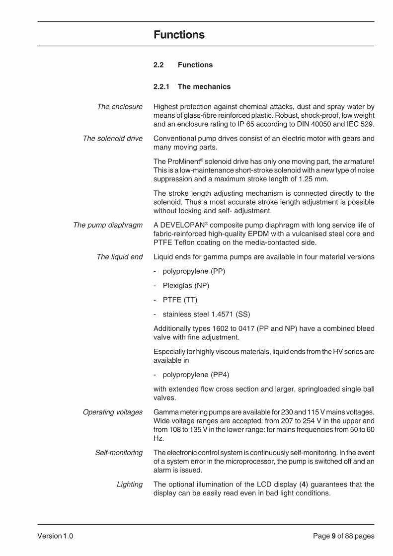
The enclosure Highest protection against chemical attacks, dust and spray water bymeans of glass-fibre reinforced plastic. Robust, shock-proof, low weightand an enclosure rating to IP 65 according to DIN 40050 and IEC 529.
The solenoid drive Conventional pump drives consist of an electric motor with gears andmany moving parts.
The ProMinent® solenoid drive has only one moving part, the armature!This is a low-maintenance short-stroke solenoid with a new type of noisesuppression and a maximum stroke length of 1.25 mm.
The stroke length adjusting mechanism is connected directly to thesolenoid. Thus a most accurate stroke length adjustment is possiblewithout locking and self- adjustment.
The pump diaphragm A DEVELOPAN® composite pump diaphragm with long service life offabric-reinforced high-quality EPDM with a vulcanised steel core andPTFE Teflon coating on the media-contacted side.
The liquid end Liquid ends for gamma pumps are available in four material versions
- polypropylene (PP)
- Plexiglas (NP)
- PTFE (TT)
- stainless steel 1.4571 (SS)
Additionally types 1602 to 0417 (PP and NP) have a combined bleedvalve with fine adjustment.
Especially for highly viscous materials, liquid ends from the HV series areavailable in
- polypropylene (PP4)
with extended flow cross section and larger, springloaded single ballvalves.
Operating voltages Gamma metering pumps are available for 230 and 115 V mains voltages.Wide voltage ranges are accepted: from 207 to 254 V in the upper andfrom 108 to 135 V in the lower range: for mains frequencies from 50 to 60Hz.
Self-monitoring The electronic control system is continuously self-monitoring. In the eventof a system error in the microprocessor, the pump is switched off and analarm is issued.
Lighting The optional illumination of the LCD display (4) guarantees that thedisplay can be easily read even in bad light conditions.
Functions

Page 10 of 88 pages Version 1.0
2.2.2 The setting range
"Pause" control By means of the universal control cable the pump can be switched on andoff voltage-free. The control function operates according to the zero signalcurrent: when the contact is open the pump is idle, brown and black wiresare not connected with each other. When the contact is closed the pumpoperates, brown and black wires are connected with each other.
The cut-in function is effective in all of the functions described in thefollowing.
> Detailed description from page 58
Internal operation "Manual" The setting of the stroke volume takes place using the stroke length (3).This can be set from 0 - 100% up to a maximum of 1.25 mm. Accuratemetering is achieved from 30% stroke length.
The stroking rate can be set with the keys (2 or 6) from 120 (100)to 0 strokes/min. The number is displayed on the display (4).
> Detailed description from page 54 onwards.
External operation "Contact" The stroke cycle of the gamma pump can also be controlled externally e.g.via a water meter contact. The connection takes place with a control cableat the connection socket (12). Each incoming pulse corresponds to onemetering stroke. A max. of 120 (100) strokes/min are possible - there is nodanger of overdriving.
Please note:The stroking rate set in the internal operation "Manual" is valid forthe external operation "Contact" as max. stroking rate.
> Detailed description from page 55
Metering monitoring "flow" Gamma metering pumps check their own performance. After the assemblyof an optional metering monitor on the liquid end (19) and activation,every complete metering stroke is recorded and passed on to the pumpelectronics. If the correct metering amount is not present eight times thepump stops.
> Detailed description from page 58
Float switch By attaching the two-stage float switch to the socket (11) the supply of fluidmedia is monitored. When a minimum height is reached an early warningis issued, the pump however continues to operate.
The pump switches off only once the level has dropped another 30 mm.
A fault annunciation relay can be switched as an option.
> Detailed description from page 56
Functions

Page 11 of 88 pagesVersion 1.0
2.2.3 Options
The versions listed below can be obtained from ProMinent individually oras a freely combinable package.
Analog Control Analogue signals can be used for proportional control of the stroking rate.The stroking rate is varied between 0 and 100% according to the 0/4 - 20mA signal.
For example, in the event of a cable rupture (input signal < 4 mA) an alarmmessage is issued and the pump switches off. Other input signals (0-1 V,0-10 V, 0-60 mV) can be entered on ordering with the identity code.
> Detailed description from page 62
Pulse Control Pulse Control is used for adapting the gamma metering pump to all typesof pacers and for saving additional control devices.
The following functions listed below can be set using the keyboard:
Pulse set-downand step-up By entering a factor in the range from 0.01 to 9999 the step-down or step-
up ratio can be set.
Example:
Step-down with factor 0.01: 100 pulses = 1 metering strokeStep-down with factor 0.25: 4 pulses = 1 metering strokeStep-down with factor 1: 1 pulse = 1 metering strokeStep-up with factor 4: 1 pulse = 4 metering strokesStep-up with factor 9999: 1 pulse = 9999 metering strokes
> Detailed description from page 67
Display "f" Displays the stroking rate in 0 to 120 (100) strokes/min.
> Detailed description from page 69
Predetermining counter "N↔" The predetermined number of strokes can be called up by means of avoltage-free contact or the P key (5). The strokes still to be executed areshown on the display (4) subtracting.
> Detailed description from page 69
Stroke counter "N" The stroke counter in all operating modes counts the strokes executedand shows these on the display (4). A maximum of 9,999 strokes can becounted, after this the display starts at 1 again.
> Detailed description from page 69
Memory "Mem" A memory with a storage capacity of 65,535 (216-1) pulses or strokes canbe additionally switched on. Thus incoming pulses can be registered andworked off.
> Detailed description from page 71
Functions

Page 12 of 88 pages Version 1.0
Relay output (9) This is used for remote transfer of alarm messages or as a pacer forremote control e.g. of a second ProMinent® metering pump in synchronouspacing operation.
The relay output can be used for:
Collective fault indication For the level early warning and final switch off, metering monitor, systemerror annunciation, fuse and mains failure annunciation. Function: relayde-energises in the event of an alarm.
Alarm relay For the level early warning and final switch off, metering monitor andsystem error message. Function: relay energises in the event of an alarm.
Pacing relay With contact pacing parallel to the discharge stroke of the meteringsolenoid. Contact duration 150 ms.
Timer relay Switches parallel to 31 different metering times (from 1 minute to up to 24hours), repeating daily or weekly.
> Detailed description from page 72
Functions

Page 13 of 88 pagesVersion 1.0
Technical Data
3 Technical data
gamma 5b, type 1602 1605 1006 1006 1310 1310 0613 0813 0813 0417 0423 0230HV HV HV
Capacity (l/h) 2.3 4.7 5.8 5.8 9.5 9.5 13.1 13.3 13.3 17.4 24.0 30.3Capacity (ml/stroke) 0.32 0.79 0.81 0.81 1.59 1.59 1.82 2.21 2.21 2.42 4.00 4.21
at max. counter pressure (bar) 16 16 10 10 13 10 6 8 8 3,5 3,5 2
Capacity (l/h) 2.74 5.76 7.06 7.06 10.8 10.8 14.9 14.6 14.6 17.9 24.6 34.5Capacity (ml/stroke) 0.38 0.96 0.98 0.98 1.8 1.8 2.08 2.44 2.44 2.48 4.1 4.8
at med. counter pressure (bar) 8 8 5 5 6 5 3 4 4 2 2 1
Suction lift (m WC) 6 6 6 6 6 6 5.5 6 6 4.5 5 2.5
Priming liftat 100% stroke length (m)** 1.0 1.3 1.3 - 1.9 - 1.9 2.0 - 2.0 1.8 1.8
Max. pressure suction side (bar) 8.0 3.5 3.5 3.5 2.0 2.0 2.0 1.5 1.5 1.5 0.8 0.8
Max. stroking rate (strokes/min) 120 100 120 120 100 100 120 100 100 120 100 120
Liquid end version*** - - PP PP - PP PP PP PP PP PP PPNP NP NP - NP - NP NP - NP NP NP
with suction and - - TT - - - TT TT - TT TT TTdischarge connections*** SS SS SS - SS - SS SS - SS SS SS
Connection sizeo.ø x i.ø (mm) 8x5 8x5 8x5 DN15 8x5 DN15 8x5 12x9 DN15 12x9 DN10 DN10
Medium power drainat max. 120 strokes/min (W) see type identification plate
at max. 100 strokes/min (W) see type identification plate
Peak power drainat discharge stroke (A) 2.1 3.1 2.1 2.1 3.1 3.1 2.1 3.1 3.1 2.1 3.1 2.1
Shipping weight. PP. NP. TT (kg) 4.6 6.7 4.6 5.1 6.9 7.4 4.8 6.9 7.4 4.8 8.0 5.9
Shipping weight. SS (kg) 5.8 7.9 5.8 - 8.5 - 6.4 8.5 - 6.4 11.4 9.3
**) Priming lifts with clean dampened valves for water and suction line asspecified.
***) Media-contacted Liquid end Suction/discharge Seals Balls Ballsmaterials for version connection 8 to 12 mm DN10/DN15
PP1 polypropylene polypropylene EPDM ceramic DuranPP2 polypropylene polypropylene FPM (Viton A) ceramic DuranPP41) polypropylene polypropylene EPDM – ceramicNP1 Plexiglas PVC FPM (Viton A) ceramic DuranNP2 Plexiglas PVC EPDM ceramic DuranTT1 PTFE with carbon PTFE with carbon PTFE with carbon ceramic ceramicSS... stainless steel 2) stainless steel 2) PTFE with carbon ceramic stainless steel 2)
1)PP4 with Hast. C valve springs, 2) material no. 1.4571, 3) material no. 1.4401DEVELOPAN® = pump diaphragm with PTFE layerPlexiglas® and Viton® (FKM) and Duran are registered trademarks.
Page 14 of 88 pages Version 1.0
Technical Data
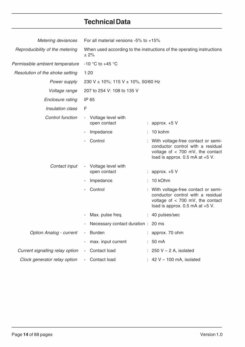
Metering deviances For all material versions -5% to +15%
Reproducibility of the metering When used according to the instructions of the operating instructions± 2%
Permissible ambient temperature -10 °C to +45 °C
Resolution of the stroke setting 1:20
Power supply 230 V ± 10%; 115 V ± 10%, 50/60 Hz
Voltage range 207 to 254 V: 108 to 135 V
Enclosure rating IP 65
Insulation class F
Control function - Voltage level withopen contact : approx. +5 V
- Impedance : 10 kohm
- Control : With voltage-free contact or semi-conductor control with a residualvoltage of < 700 mV, the contactload is approx. 0.5 mA at +5 V.
Contact input - Voltage level withopen contact : approx. +5 V
- Impedance : 10 kOhm
- Control : With voltage-free contact or semi-conductor control with a residualvoltage of < 700 mV, the contactload is approx. 0.5 mA at +5 V.
- Max. pulse freq. : 40 pulses/sec
- Necessary contact duration : 20 ms
Option Analog - current - Burden : approx. 70 ohm
- max. input current : 50 mA
Current signalling relay option - Contact load : 250 V – 2 A, isolated
Clock generator relay option - Contact load : 42 V – 100 mA, isolated

Page 15 of 88 pagesVersion 1.0
4 Installation dimensions
gamma/5b A B C D E F G
1602 NP 276 200 40 70 8x5 95 50
1006 NP 269 208 32 85 8x5 95 50
1602 a 1006 PP 271 207 38 70 8x5 95 50TT 259 208 13 80 8x5 97 50
SS1 259 220 19 80 8x7 97 50
1310 a 0613 PP 271 212 28 90 8x5 95 66NP 269 215 23 100 8x5 95 66TT 259 237 3 95 8x5 97 66
SS1 259 230 10 95 8x7 97 66
0813 to 0417 PP 271 212 28 90 12x9 95 66NP 259 215 23 100 12x9 97 66TT 259 237 3 95 12x9 97 66
SS1 259 230 10 95 12x10 97 66
0423 and 0230 PP 258 275 17 135 DN10/23x16 96 117NP 258 275 17 135 DN10/23x16 95 117TT 258 234 6 135 DN10/d16 95 117
SS1 258 234 6 135 DN10/R3/8" 95 117
1006 HV PP4, PP5, PC4 269 193 47 85 DN15 103 50
1310 HV PP4, PP5, PC4 270 193 47 85 DN15 104 66
0813 HV PP4, PP5, PC4 270 200 40 100 DN15 104 66
Installation Dimensions
for TT = DN 10 for SS1 = DN 10Versionfor PP/NP = DN 10for PP4 = DN 15

Page 16 of 88 pages Version 1.0
EC Declaration of Conformity
We, ProMinent Dosiertechnik GmbHIm Schuhmachergewann 5 - 11D - 69123 Heidelberg
hereby declare that, on the basis of its functional concept and design and in the version brought into circula-tion by us, the product specified in the following complies with the relevant, fundamental safety and healthstipulations laid down by EC directives.Any modification to the product not approved by us will invalidate this declaration.
Product description: Metering pump, Series gamma/ _b
Product Type: G/4b… , G/5b…
Serial number: See type identification plate overleaf and on device
Relevant EC EC - machine regulation (89/392/EEC)regulations: subsequently 93/44/EEC
EC - low voltage regulation (73/23/EEC)EC - EMC - regulation 89/336/EEC
subsequently 92/31/EEC
Harmonised standards used, EN 292-1 , EN 292-2 , EN 809in particular: EN 60335-1 A6 , EN 60335-2-41
EN 50081-1/2 , EN 50082-1/2 , EN 55014EN 60555-2 , EN 60555-3
National standards and DIN VDE 0700 T1 , DIN VDE 0700 T41 , DIN VDE 0700 T500technical specifications CSA Standard C 22.2 No. 0 - M 91 (115 V-Version)used, in particular: CSA Standard C 22.2 No. 108 - M 89 (115 V-Version)
Date/manufacturer's signature: .......................................................................
The undersigned: Mr. Manfred Hüholt, factury manager
28.03.1996
Conformity Declaration
Page 17 of 88 pagesVersion 1.0
6 Accessories
WARNINGProMinent metering pumps may not be assembled withforeign parts which have not been tested and recommendedby ProMinent. Failure to observe this may result in perso-nal injury and damage to property for which no liability isaccepted!
6.1 Float switch
Order no. 14.20.93.4 Two-stage with 2 m connection cable
6.2 Control cables
Order no. 70.77.18.3 4-wire, 2 m, universal control cableOrder no. 70.77.02.7 2-wire, 2 m, remote contact cable
6.3 Foot valves
With suction filter and ball check valve for connection at the end of thesuction line.
6.4 Injection valves
With spring-loaded ball check valve for metering into open or closedsystems and for fastening the discharge line.
6.5 Injection lances
For metering into large pipe cross sections and for preventing blockagesfor media which effloresce.
6.6 Back-pressure valves / multifunction valves
For accurate metering at low counter pressure or as relief safety valve.
6.7 Accumulators
For pulsation dampening e.g. for long discharge lines.
6.8 Metering monitors
For monitoring the metering, after eight non acknowledged strokes anerror message is displayed and the metering pump is switched off.
6.9 Suction lances
With foot valve and float switch for disposable drums or supply tanks.
6.10 Supply tanks
From 35 to 1000 l content with lockable screw cap and necessaryaccessories.
Accessories
!

Page 18 of 88 pages Version 1.0
6.11 Manual/electric stirrers
For mixing and preparing metering solutions.
6.12 Console
For stable mounting of the pump.
7 SAFETY INSTRUCTIONS
WARNING:Pumps must be accessible at all times for operation andservice. Accesses may not be closed off or blocked!
WARNING:If hazardous or unknown metering media are used, always firstempty out the liquid end and rinse it out for maintenance andrepair work! Observe the safety data sheets of the meteringfluids!
WARNING:When metering dangerous or unknown fluids, protectiveclothing must be worn when working on the liquid end(glasses, gloves)!
WARNING:When operating the metering pump against a closed shut-off element on the delivery side, the resulting pressurebuild-up can reach a multiple of the maximum permissiblebackpressure!This can cause the delivery line to burst!To avoid this, it is advisable to install a ProMinentmultifunction valve which limits the maximum pressurewhich can be reached!
WARNING:When metering combustible media, the correspondingnational and international regulations (ExVo, VbF,DIN VDE 0165) must be observed!
ATTENTIONOnly set the stroke length when the pump is running when thesetting bolt of the metering stroke is briefly relieved!
PLEASE NOTE:Only use the gripper rings and hose nozzles specified for therespective hose diameter as well as original hoses with specifiedhose dimensions and wall thickness as otherwise the stabilityof the connection is not guaranteed!Avoid reducing the hose sizes!For long lines and highly viscous media the next highest linediameter or a pulsation dampener should be used!
SAFETY INSTRUCTIONS

Page 19 of 88 pagesVersion 1.0
8 Device identification/identity code
The type identification plate affixed on the title page is identical to that on thesupplied pump thus enabling specific allocation between operating instructionsand the pump. Please enter the identity code specified under "Type" on the typeidentification plate in the grey entry field below.
IDENTITY CODE
Device identification/identity code
Control version:
Pulse Control:
Switching mode of relay:Control type:
Connectionn:
Version perspex cover:
Electrical connection:Mains cable 2 m long
… … … … … … … … …G/5b … … … … … … …
Series:G/5b = gamma 5, version b
Valve springs:
Liquid end material:
Pump type:Number 1+2 = counter pressure (bar)Number 3+4 = capacity (l/h)
1602*1605*10061310*
*only available in NP and SS
G/5b-005-GB
06130813041704230230
Timer/serial interface*:(separate operating instructions)
PP1 = polypropylenwith EPDM O-ring
PP2 = polypropylenwith Viton O-ring
PP4 = polypropylen HVfor high viscosity mediawith EPDM O-ring andHast.C valve springs(only for 1002, 1006,1310, 0813)
NP1 = Plexiglas with VitonO-ring
TT1 = carbon-loaded PTFE,PTFE seal
SS1 = s/s 1.4571,PTFE seal
SS2 = s/s with1/4" NPT thread
= special version........................
0 = without springs1 = with 2 springs
1.4571 - 0.1 bar
0 = standard according to technical data
= special version........................
0 = standard 1 = with lock
= special version........................
0 = manual + remote + pause1 = as for 0 + analog
0 - 20 mA, 4 - 20 mA2 = as for 0 + analog
0-60 mV, 0-1 V, 0-10 V= special version
........................
0 = Without timer1 = With timer2 = Terminal RS 232
data cable 2 m3 = Terminal RS 485
data cable 2 m4 = Terminal RS 232
data cable 10 m5 = Terminal RS 485
data cable 10 m* Arelay cannot be selected
for the selection RS interface != special version
........................
0 = without pulse control1 = with pulse control
= special version........................
0 = without relay1 = ault annunciation relay,
de-energising2 = pacing relay, energising3 = fault annunciation relay,
energising4 = timer relay, energising
= special version........................
A = 230 V, 50/60 HzEuro plug
B = 230 V, 50/60 HzSwiss plug
C = 230 V, 50/60 HzAustralian plug
D = 115 V, 50/60 HzUS plug
= special version........................
0 = basic type*1 = option type2 = option type with
LCD illumination* when selecting basic type
"0"all the following optionsmust be "0" != special version
........................
Page 20 of 88 pages Version 1.0
Unpacking
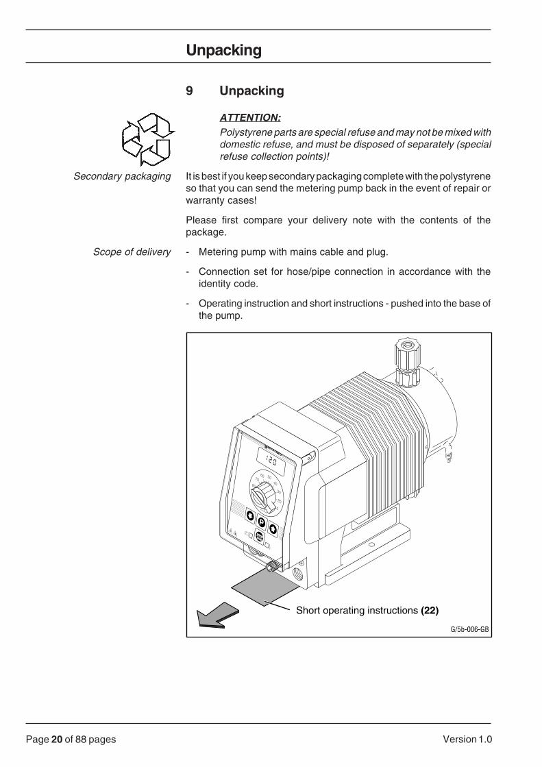
9 Unpacking
ATTENTION:Polystyrene parts are special refuse and may not be mixed withdomestic refuse, and must be disposed of separately (specialrefuse collection points)!
Secondary packaging It is best if you keep secondary packaging complete with the polystyreneso that you can send the metering pump back in the event of repair orwarranty cases!
Please first compare your delivery note with the contents of thepackage.
Scope of delivery - Metering pump with mains cable and plug.
- Connection set for hose/pipe connection in accordance with theidentity code.
- Operating instruction and short instructions - pushed into the base ofthe pump.
10
20
30
40
5060
7080
90
100
STOPSTOPSTARTSTART
P
gamma/5
Short operating instructions (22)
G/5b-006-GB

Page 21 of 88 pagesVersion 1.0
ATTENTION:Check that the details on the identification plate match the orderdetails!
If they do not, immediately notify the ProMinent subsidiary or representativeresponsible for you (addresses can be found on the back page of theseoperating instructions).
ProMinent Dosiertechnikim SchuhmachergewannD-69123 HeidelbergTel. 06221/8420Made in GermanyA 93 00…
TYPESER.NR./PN.POWER SUPPLYAMP.PULSDOSING RATE
G/5B1006PP1000A000000093…230 V 50/60Hz43W5,831l/h 10bar
G/5b-007-GB
0 0 0 A 0 0 0 0 0G/5b 1006 PP1
Each gamma 5 metering pump is provided with an identification plate.This can be found on the base of the pump.
G/5b-008-D
In addition to the technical basic data the IDENTITY CODE and the serialno. are specified. Both numbers are to be stated during any enquiry orwhen ordering spare parts as they permit a clear identification of thepump type and material variant.
Please make a note of the following details of the pump delivered so thatthese are always available when required:
Unpacking

Page 22 of 88 pages Version 1.0
IDENTITY CODE
__________________________________________________
Serial number
__________________________________________________
Place of installation
__________________________________________________
__________________________________________________
Metering application
__________________________________________________
Commissioning
__________________________________________________
10 Installation
10.1 Installing the pump: mechanical part
10.1.1 Pump installation with console or tank
• Assemble metering pump onto a container or a console with screwsand washers (dia. 6 mm).
PLEASE NOTE:The pump must be fastened in such a way that no vibrations canarise!The valves of the liquid end must always be kept upright in orderto guarantee that they function smoothly!
10.1.2 Connection of suction/discharge line to the pump
PLEASE NOTE:Suction and discharge lines must always be laid in such a way thata stress-free connection at the liquid end is ensured.Lines must be fastened so that no vibrations can arise!
PLEASE NOTE:When metering extremely aggressive or dangerous media werecommend a bleeding with backfeed to the tank! Additionally, anisolating valve should be provided at the discharge and suctionside!
Installation

Page 23 of 88 pagesVersion 1.0
G/5b-009-GB
Dischargeconnection
Suction connection
Nozzle >
Union nut >
< Gripper ring >(Position of the
gripper ring)
O-ring >
Hose line >
• Lay lines in such a way so that if necessary the pump and lines can beremoved to the side.
• If the suction/discharge connection is closed with a plug pleaseremove this.
• Attach the suction line to the suction connection.
• Attach the discharge line to the discharge connection.
Hose lines Hose lines:
• Pull the union nut and gripper ring over the hose line.
• Push the hose end cut straight onto the nozzle up to the stop.
• If necessary widen the hose end a little.
• If used for several connections shorten the hose end approx. 10 mmby cutting it straight.
PLEASE NOTE:Only use the gripper rings and hose nozzles for the respectivehose diameter as well as original hoses with specified hosedimensions and wall thickness. If this is not observed the stabilityof the connection is not guaranteed!Avoid reducing the hose sizes!For long lines and viscous media the next highest line diametershould be used!
• Push on the hose and simultaneously tighten the union nut.
Installation

Page 24 of 88 pages Version 1.0
PLEASE NOTE:You obtain a fixed hose connection if you pull shortly on the lineconnected to the liquid end and subsequently retighten the unionnut "hand-tight"!
Stainless steel pipe connections Stainless steel pipe connections:
• Push up the union nut and the gripper ring on to the pipe so that theyproject approx. 10 mm.
• Insert the pipe into the valve until the stop and initially tighten the unionnut with your fingers.
For initial assembly continue to tighten the union nut another 1 1/4turns.
When remounting tighten 1/4 turn further.
PE/PTFE lines PE/PTFE lines:
• When connecting to stainless steel valves additionally insert a stainlesssteel ferrule into the plastic hose.
G/5b-010-D
Order no. 35.93.65.4 Ferrule for hose 6x4 mmOrder no. 35.93.66.2 Ferrule for hose 8x5 mmOrder no. 35.93.68.8 Ferrule for hose 12x9 mm
10.1.3 Installation suction line (general instructions)
Please note:Keep the suction line as short as possible!Size the diameter and length so that the underpressure arisingwhen sucking does not reach the steam pressure of the media tobe fed!The suction line must be laid ascending in order to prevent airbubbles from forming!For bends use arcs and not angles if possible!
Please note:Too high underpressure on the suction side in extreme casesleads to the fluid column tearing or an incomplete return stroke!
NB:Height (h) x density (d) max. suction lift in mWC!
Installation

Page 25 of 88 pagesVersion 1.0
Installation
• Assemble foot valve.
• For this purpose shorten the free suction line end so far that the footvalve is hanging just above the floor of the container.
• For metering solutions with impurifications or feculence shorten thefree end of the suction line so far that the foot valve is hanging at least50 mm over the floor of the container.
10.1.4 Installation discharge line (general information)
ATTENTION:Lay the discharge line in such a way that pressure peaks duringthe metering stroke do not exceed the maximum permissibleoperating pressure (if necessary use a relief valve)!
WARNING:When operating the metering pump against a closed isolatingvalve on the discharge side, the counter pressure can reachthrice the max. permissible counter pressure!
As a result the discharge line can burst!
In order to prevent this, a relief valve is recommended whichlimits the max. permissible counter pressure!
10.1.5 Installation bybass bleed line
Liquid end with bleed valve For the liquid end versions NP and PP up to type 0417 a bleed valve (17)with bypass (18) is present on the liquid end.
• Plug on hose line with 4 mm interior dia. (max. 6mm) onto the bypasshose nozzle, preferably use PVC soft 6 x 4 mm.
• For PE lines this should be secured against slipping off for example byusing a quick fastening cable clamp.
• Lead the free end of the line back into the supply tank.
• Connect the discharge line directly to the discharge connection and tothe injection valve.
!

Page 26 of 88 pages Version 1.0
10.1.6 Installation examples
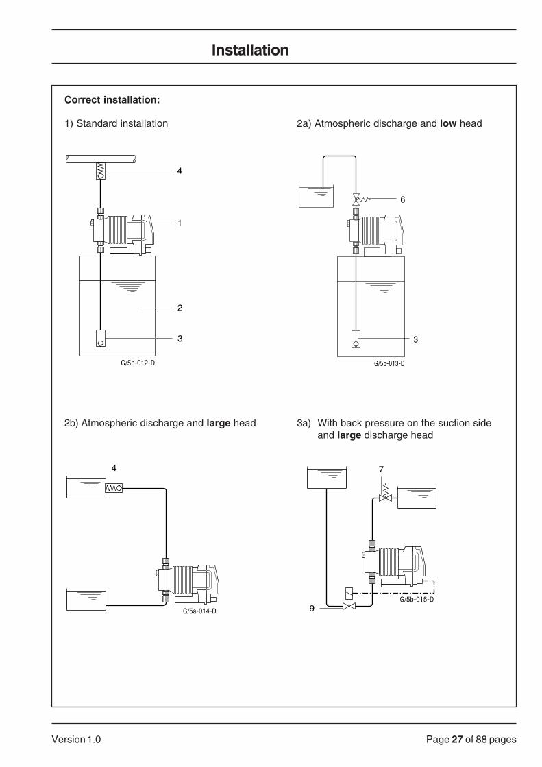
Explanation of the individual elements:
1 Metering pump2 Supply tank3 Foot valve with strainer and ball check valve4 Injection valve, spring-loaded5 Injection valve with reinforced spring6 Back-pressure valve TYPE DK (liquid end assembly)7 Back-pressure valve TYPE DL (discharge line installation)8 Accumulator9 Solenoid valve
10 Drain valve11 Bleed valve12 Isolating valve
Important:Height (h) x density (d) max. suction lift in mWC!
gamma 5b, type 1602 1605 1006 1006 1310 1310 0613 0813 0813 0417 0423 0230HV HV HV
Priming liftat 100% stroke length (m) 1.0 1.3 1.3 - 1.9 - 1.9 2.0 - 2.0 1.8 1.8
Suction lift (mWC) 6.0 6.0 6.0 6.0 6.0 6.0 5.5 6.0 6.0 4.5 5.0 2.5with liquid end filled
Installation
Page 27 of 88 pagesVersion 1.0
Installation
Correct installation:
1) Standard installation 2a) Atmospheric discharge and low head
4
1
2
3
G/5b-012-D
6
G/5b-013-D
3
2b) Atmospheric discharge and large head 3a) With back pressure on the suction sideand large discharge head
4
G/5a-014-D
7
9G/5b-015-D

Page 28 of 88 pages Version 1.0
3b) With back pressure on the suction side and 4a) Installation to safely prevent siphoning of low discharge head hazardous media
6
9
G/5b-016-D
7/5
G/5b-017-D
4b) Installation to safely prevent siphoning of hazardous media
6
7
G/5b-018-D
5) With long suction or discharge lines
7 12 11 8 10 12 4
12 11 8 10 12
G/5b-019-D
Installation

Page 29 of 88 pagesVersion 1.0
6 For pulsation-free meteringa) into discharge lines
7 12 11 8 10 12
4
G/5b-020-D
b) into an atmospheric system c) without overfeeding
7 12 11 8 10 7
G/5b-021-D
7 12 11 8 10 9
Nozzle
G/5b-022-GB
7) To protect against overpressure 8) Metering into vacuum
5
9
6
G/5b-024-D
3
Installation
4
7
G/5b-023-D
3

Page 30 of 88 pages Version 1.0
9) With media tending to emit fumes and vapours 10) Pulse type individual metering
G/5b-025-D
4
12
4
6
G/5b-026-D
3
11) Here BPV correct
h
G/5b-027-D
7
Calculation of the max. permissible line height hmax above the back-pressure valve:
P x 14.3hmax. < = –––––––
Rho x g
hmax.
Max. line height (m)P pre-stress pressure set (bar)g gravitation constant (10 m/s2)Rho density of the medium to be fed (kg/dm3)
Installation

Page 31 of 88 pagesVersion 1.0
Incorrect installation:
12) Suction line too high 13) Suction line cannot be bled
G/5b-028-D G/5b-029-D
14) Free flow, media will be 15) Accumulator ineffectivegravity-fed through pump
G/5b-030-D
G/5b-031-D
Installation

Page 32 of 88 pages Version 1.0
10.2 Installation pump: electrical part
10.2.1 Electrical connection (general instructions)
WARNING:Only connect the pump to the power supply with theappertaining plug!
Mains voltage Mains voltage:
230 V ± 10%, 50/60 Hz or
115 V ± 10%, 50/60 Hz
PLEASE NOTE:Frequent switching on and off only via the voltage-free controlfunction "START/STOP"!
Switching on and off via the mains supply only when voltage-freecontrol is not possible!
Voltage-free contact Switch element voltage-free contact e.g. switch, reed relay, optocoupleror open collector with residual voltage < 700 mV; contact load approx. 0.5mA at 5V
Analogue control signals • The voltage of the analogue control signals must be separated.
• After switching off the pump from the mains this always restarts in thelast operating mode set (even after being disconnected from the mainsfor several years).
• If when doing so the whole LCD display (4) flashes, stop this by
pressing the P key.
• If present, connect the connection cable metering monitor to the pumpafter removing the protective cover from the connection socket (10).
• If present, connect the float switch to the pump after removing thefunction plug from the connection socket (11).
• If present, connect the contact/control cable to the pump after removingthe function plug from the connection socket (12).
PLEASE NOTE:The connection sockets (11 and 12) must always be used! Eitherby the function plug, by means of a built-in shorting bar or bymeans of a float switch or contact/control cable!Always keep the function plug for reuse after you have removedit!
Installation
!
Page 33 of 88 pagesVersion 1.0
Installation
10.2.2 Operating modes
Manual (internal operation)The pump operates with the stroking rate set manually. This is set
between 0 and 120 (100) strokes per min. using the and
keys.
AnalogControlling the pump from an analogue signal, e.g. 4-20 mA. The strokingrate is set proportional to the control signal. The maximum stroking rateis the number of pulses which is set in manual operation beforeprogramming the pump. Pin allocation see page 35.
Contact (external operation)Controlling the pump via voltage-free contacts (e.g. water meters). For the"pulse control" option the incoming pulses can be stepped up or steppeddown. The maximum stroking rate is the number of pulses which is set inmanual operation before programming the pump. Pin allocation seepage 35.
10.2.3 Functions superior to the operating modes
Start/stop key
The pump can be stopped at any time by pressing the STOPSTART key and
started again with the last setting by pressing this key again.
Control function "PAUSE"Switching the pump on and off via the "PAUSE" control function using auniversal cable and voltage-free contact. Pin allocation see page 35.
Empty message "LEVEL"Connection possibility of a two-stage float switch. If the level of the fluidin the supply container sinks to approx. 30 mm above minimum an earlywarning is issued. For the "fault annunciation relay" option the built-inrelay switches and the pump continues to operate. If the level sinks anylower the pump is stopped. Pin allocation see page 35.
Option "Timer"With the timer released the pump can only meter during the switch-ontimes set.

Page 34 of 88 pages Version 1.0
Installation
10.2.4 Parallel connection
If in exceptional cases the mains voltage of the pump has to be connectedin parallel with an inductive load e.g. solenoid, motor or similar it must bepossible for the metering pump to be separated electrically from thesewhen the other loads are switched off. Therefore own contacts must beprovided for the pump.
The power supply must take place over an auxiliary contactor or a relay.
If this is not possible
- a varistor RV (order no. 71.09.12.7)
- or an RC combination (0.22 µF/220 ohm, order no. 71.08.02.0)
must be connected in parallel to render the induced voltage harmless.
Isolation by means of a multi-pole contactor or switch, if the inductive loadPMV is < 20 W the pump PM and the load MV could have a common controlcontact.
MV PM
U
MVPM
U
RV
G/5b-033-D
RV
U supply voltageMV solenoid valve, motor or similarPM ProMinent metering pumpRV Varistor
Page 35 of 88 pagesVersion 1.0
Installation
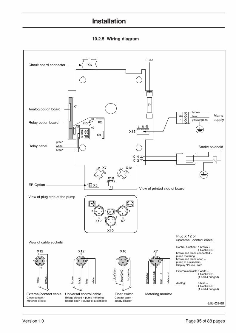
10.2.5 Wiring diagram
13
brown
blueyellow/green
21 X5
1
2
3
4
X7
Mainssupply
Stroke solenoid
1
2 3X10
1
2
3
4
X12
X1
X14X13
X15
L N
F1
Fuse
Analog option board
Relay option board
EP-Option
Float switchContact open -empty display
X6
Relay cabel
Circuit board connector
Metering monitor
Plug X 12 or universal control cable:
Control function : 1 brown + 4 black/GNDbrown and black connected =pump meteringbrown and black open =pump at a standstill, Display "Pause Stop"
External/contact: 2 white + 4 black/GND (1 and 4 bridged) Analog: 3 blue + 4 black/GND (1 and 4 bridged)
G/5b-032-GB
X8X2
X9
NCNO
C
NO
C
green
white
braun
NC
2
4X7
X10
X12
13
2
4
1
23
External/contact cable Universal control cableClose contact -metering stroke
4
2
31
X12
whi
te
brow
n +
X12
brow
n
blac
k
blue
whi
te
4
2
31
1
2 3
X10
blue
/ala
rm
blac
k/G
ND
brow
n/st
op
View of printed side of board
1
2
3
4
X7
brow
n/5V
blac
k/G
ND
blue
whi
te/c
od.
View of plug strip of the pump
View of cable sockets
Bridge closed = pump meteringBridge open = pump at a standstill

Page 36 of 88 pages Version 1.0
Commissioning
11 Commissioning
11.1 General instructions
WARNING:The metering pump may still contain water in the liquid endfrom the test at the factory!
For media which may not come into contact with water, thewater must be emptied before the pump is used. For thispurpose turn the pump 180 ° and empty the liquid end, thenrinse with a suitable agent via the suction connection fromabove.
ATTENTION:Only set the settings when the pump is running and when thesetting bolt of the metering stroke is briefly relieved.
11.2 Operating conditions
Permissible ambient temperature -10 °C to +45 °C
up to +50 °C with short time operation up to 1 hour operating time at max.stroking rate;above +45 °C continuous operation the max. stroking rate must belowered for each 1 °C by approx. 3 strokes per minute from the max.stroking rate.
Relative humidity 10 to 92%, non-condensing
Permissible media temperaturein the liquid end Material Long term at max. Short term
permissible counter pressure max. 15 mins. at 2 bar
NP 45 °C 60 °CPP 50 °C 100 °CTT 50 °C 120 °CSS 50 °C 120 °C
PLEASE NOTE:A brief excess of the specified temperatures is for example onlypermissible for sterilisation or rinsing with hot water!
11.3 Suction capacity/bleeding
The max. priming lift of the gamma 5a metering pump with dampenedvalves is between 1.0 and 2.0 mWC depending on the type.
The pump cannot prime against a head.
The suction lift with the liquid end filled and bled is between 2.5 - 6 mWCdepending on the type of pump.
!

Page 37 of 88 pagesVersion 1.0
Liquid end without bleed valve • DN 10 Connect discharge line to liquid end, however not to injectionversion TT, SS and from valve.
• Operate metering pump with stroke length/stroking rate 100% andpressure-free discharge line by simultaneously pressing
the and -keys until the medium has completely filled the
liquid end without any bubbles.
This can be verified by the medium being visible in the discharge lineor when it comes out of the discharge line.
• Now fasten the discharge line to the injection valve.
Installation instructions/ • For long suction and discharge lines with low flow resistance, usecommissioning fittings and mounting parts, e.g. arcs instead of angles, install pulsation
HV version (PP4) dampener near the metering pump; increase diameter by one nominalwidth.
• Initial priming and bleeding is made difficult by the valves and valvesprings still being dry. Therefore select as short a priming lift aspossible or bleed the liquid end with influx or response pressure on thesuction side. If this is not successful, we recommend the followingprocedure: unscrew the discharge connection, press away the ballfrom the O-ring seat and fill the liquid end with water or suitable fluid.After this assemble the discharge connection without the valve spring,push a short length of PVC hose (approx. 100 mm) onto the hosenozzle and fill with water halfway. Let the pipe operate at max. strokelength until the metering is visible in the hose. Then re-insert the valvespring. In order to prevent tilting, insert a mandrel with an approx.diameter of 4 mm through the head valve and thus keep the spring inthe central position. Reconnect the discharge line, the pump is readyto operate.
• If the capacity is reduced, we recommend working with a longer strokelength and decreased stroking rate.
Liquid end PP, NP • If possible proceed as for version TT, SS and from DN 10.with bleed valve If this is not possible,
• connect the discharge line to the liquid end and the injection valve.
17b
17
G/5b-011-D
17a
Coarse bleeding • Open bleed valve (17) by turning it anti-clockwise.
• Now the passage is open for coarse suction bleeding via the bypass.
Commissioning

Page 38 of 88 pages Version 1.0
• Start the pump with stroke length/stroking rate at 100% and discharge
line free of pressure by simultaneously pressing the
and keys until the medium has completely filled the liquid end
and is free of bubbles. This can be verified by the medium being visiblein the discharge or bleed line.
• Close the bleed valve. The metering pump is ready to operate.
Fine bleeding For media which slightly emit gases the fine bleeding (17) can be setcontinuously for liquid ends with bleed valves:
• For this purpose after pulling off the attached star handle (17b) openthe screw (17a) inside the bleed valve with a screwdriver approximal1 turn anti-clockwise.
• This results in a partial flow of the metering quantity constantly beingreturned to the supply tank!
• The backfeed quantity should be approx. 20% of the metering quantity!
• The media must be fluid and without solid particles.
Warning!The above mentioned measures do not guarantee any totallyreliable metering after the pump has been idle! It is essentialthat regular checks are carried out.
PLEASE NOTE:If the backfeed line ends above the fluid level, the fine bleedingvalve operates as a vacuum breaker and prevents the supply tankfrom being sucked empty if vacuum occurs in the discharge line!
After approx. 24 operating hours the screws in the liquid end areto be tightened crosswise.
AttentionIt is essential that the torque for the screws is observed. Torquefor screws M5 x 45, M5 x 60 and M5 x 70: 4.5 to 5 Nm!
11.4 Metering accuracy
All details are related to metering capacity measurements with water ata temperature of 20 °C.
When conditions remain unchanged (same counter pressure, samestroke length, stroking rate, operating temperature, mains voltage, suctionlift, medium temperature, same medium, and same diameter/length/material of the line) the metering reproducibility is ± 2% during shortperiods and for a stroke length setting of at least 30% in accordance withthe following instructions.
Commissioning
!

Page 39 of 88 pagesVersion 1.0
Commissioning
Accurate metering is only possible if the counter pressure remains fairlyconstant; this should be above 1 bar.
When metering with atmospheric discharge, an injection valve with 0.5bar response pressure should be assembled at the end of the line. Or aback-pressure valve should be assembled directly onto the liquid end inorder to create and maintain a counter pressure of approx. 1.5 bar.
If the level of the fluid of the supply tank is above the pump in operatingcondition, the response pressure is on the suction side. In this case thecounter pressure should be so high that a minimum differential pressureof 1.5 bar exists. If this is not the case a back-pressure valve or a spring-loaded injection valve with the respective response pressure should beused.
PLEASE NOTE:A back-pressure valve or a spring-loaded injection valve is not anabsolutely leakproof isolating valve!
Therefore on the suction side an isolating valve is to be installed which isclosed when the pump is idle.
An output flow once set and possibly confirmed by calibration can bereproduced exactly by setting the stroking rate. This is processed digitallyand reacts without mechanics absolutely linear. Thus an excellentreproducibility is ensured.
ATTENTION:For accurate metering please observe the following:The metering capacity of the pump was determined in warmoperating condition (min. 3 hours continuous operation at maxi-mum stroking rate)!Due to the characteristic data of the gamma 5 metering pumphigher capacities can occur until the operating temperature isreached.

Page 40 of 88 pages Version 1.0
11.5 Determining the capacity by means of nomograms
11.5.1 General information
• Turn to the page with the nomogram of your pump type and determinethe correction factor required.
Lower diagram • On the lower diagram "Capacity in relation to back pressure" mark yourback pressure present.
• Starting from the value determined (bar) proceed upwards verticallyuntil the curve and then horizontally to the left - now you can read offthe correction factor.
• Divide the capacity required by the correction factor determined - younow have the capacity in l/h or ml/min.
Middle scale • Enter your result in l/h or ml/min in the middle scale "Capacity ...".
• Take a ruler and draw a horizontal line through the capacity marked toboth the outside scales. In doing so choose an integer value as high aspossible for the stroke length. On the right hand scale you obtain therespective stroking rate.
Left scale • On the left scale "Stroke length adjustment..." read off the value for thestroke length and set this at the pump with the stroke adjustmentknob (3).
Right scale • On the right scale "Stroking rate setting..." read off the value for the
stroking rate and set this at the pump with the or key.
> Detailed description from page 53
PLEASE NOTE:In order to obtain a balanced setting draw a horizontal line throughthe next highest stroke length with an even number!
For high viscosity media and media tending to emit gases selecta large stroke length and a correspondingly low stroking rate!
For a good mixing effect choose a short stroke length and a highstroking rate!
For accurate metering the stroke length should not drop below30%!
Determining accurate metering:
• Determine the capacity to be attained on the suction side of themetering pump with a measuring cylinder or by balancing.
• If necessary correct the pump setting.
The measurements to determine the capacity for the following nomogramswere carried out with water and the correction factor determined at astroke length with 70%; variation of the capacity for all material versions-5% – +15%
Commissioning

Page 41 of 88 pagesVersion 1.0
11.5.2 Nomogram 1602
Commissioning

Page 42 of 88 pages Version 1.0
Commissioning
11.5.3 Nomogram 1605

Page 43 of 88 pagesVersion 1.0
11.5.4 Nomogram 1006
Commissioning

Page 44 of 88 pages Version 1.0
Commissioning
11.5.5 Nomogram 1310

Page 45 of 88 pagesVersion 1.0
11.5.6 Nomogram 0613
Commissioning

Page 46 of 88 pages Version 1.0
Commissioning
11.5.7 Nomogram 0813

Page 47 of 88 pagesVersion 1.0
11.5.8 Nomogram 0417
Commissioning

Page 48 of 88 pages Version 1.0
Commissioning
11.5.9 Nomogram 0423

Page 49 of 88 pagesVersion 1.0
Commissioning
11.5.10 Nomogram 0230

Page 50 of 88 pages Version 1.0
12 Operation
12.1 Explanation of the operating and display elements
12.1.1 Display
Minimum
Relais
Manual ContactAnalog
StopError PausemVmA f
G/5b-043-D
ba c d e
s r q p n
f
hi
l
v
t Nk
m
flowAuto.Mem.
o
u
g
a = Display or an error message "Error"
b = Pump stopped using "Pause" control function
c = Pump stopped manually with key (7)d = Display "Relay" is activated
e = Voltage range selection "mV" or "V"
f = Display of the time
fg = Timer operation
h = Display of the stroking rate or "E" in "Contact" operation
i + k = display of the pulse step-up or step-down ratio
k = Stroke count "N"
l = Signal range selection "mA"
m = Saving new settings
n = Activating metering monitor "flow"
o + c = Display for automatic pump stop in timer operation
p = Pump set to "Contact" operation
q = Display memory operation"mem"
r = Pump set to "Analog" operation
s = Pump set to "Manual" operation
t = Display for lack of chemical "Minimum"
(precondition: float switch connected)
u = Display of the number values set
v = Display for excess stroke counting and for switch-offtime" "
Only for gamma Remote Control:a + i = No mains supply of the metering pump,error in the data
transfer line
Operation
Page 51 of 88 pagesVersion 1.0
12.1.2 Control panel: keys and display lamps
STOPSTART
P
2 5 6
7 G/5b-044-D1 8
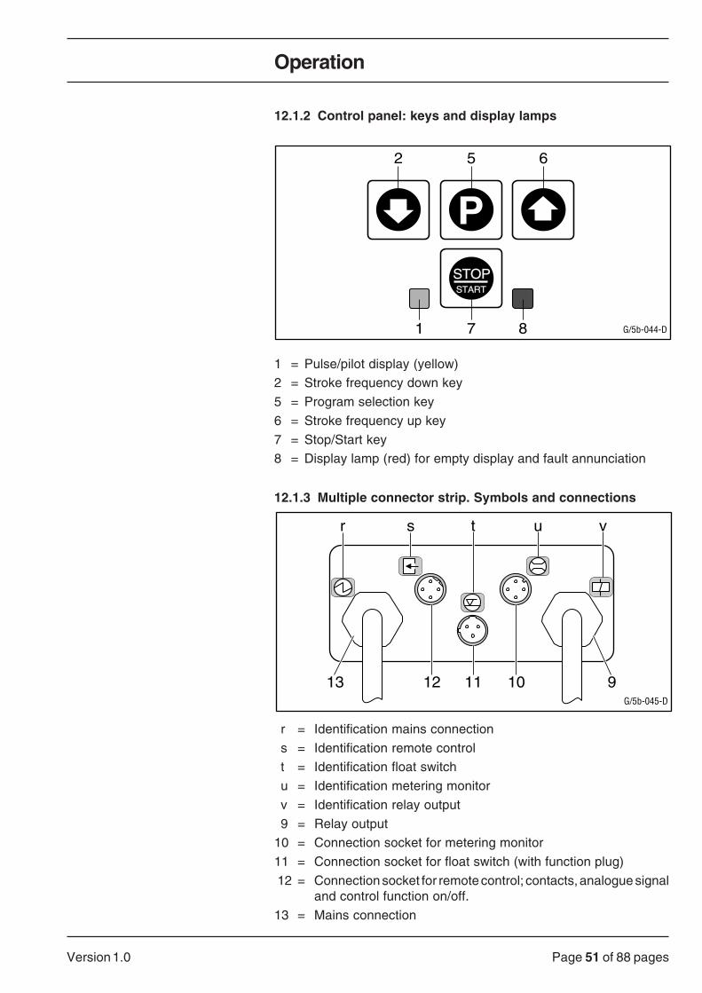
1 = Pulse/pilot display (yellow)
2 = Stroke frequency down key
5 = Program selection key
6 = Stroke frequency up key
7 = Stop/Start key
8 = Display lamp (red) for empty display and fault annunciation
12.1.3 Multiple connector strip. Symbols and connections
G/5b-045-D
sr t u v
13 12 11 10 9
r = Identification mains connection
s = Identification remote control
t = Identification float switch
u = Identification metering monitor
v = Identification relay output
9 = Relay output
10 = Connection socket for metering monitor
11 = Connection socket for float switch (with function plug)
12 = Connection socket for remote control; contacts, analogue signaland control function on/off.
13 = Mains connection
Operation

Page 52 of 88 pages Version 1.0
Operation (Basic Version)
12.2 Overview operating diagram
< Press the key at least 2 secs
G/5b-055-GB
P
P
P
P
P
STOPSTART
Increase stroking rate
Decrease stroking rate
Metering monitoring on
Metering monitoring off
Priming
Start pulse at contact
Error confirmation
Pumpstops
Pumpoperates
Manual
STOPSTART
Operating mode
Manual
Stop
fPManual
Contact
PContact

Page 53 of 88 pagesVersion 1.0
12.3 Operating functions basic version
12.3.1 Starting the pump
• Plug the mains plug into the socket.
• Open the view window (14).
• Set the stroke length to 100% with the stroke adjustment knob (3).
• Press the STOPSTOP
START key in order to avoid uncontrolled feeding.
• Only for NP and PP pumps: Open bleed valve (17) max. 1 turn anti-clockwise.
• Only for SS and TT pumps: Loosen the discharge line at the injectionvalve.
• Simultaneously press the keys and start automatic quick
priming.
• Press the keys so long until the medium has completely filled the liquidend free of bubbles - this can be recognised by the fact that the mediumbecomes visible in the bleed or discharge line.
• Close bleed valve (NP/PP) or fasten the discharge line again to theinjection valve (SS/TT).
PLEASE NOTE:
By simultaneously pressing the keys the pump
operates in all operating conditions with maximum stroking ratein order to guarantee a safe and fast priming!
12.3.2 Stopping the metering
The metering can be interrupted at any time by pressing the STOPSTOPSTART key
- "Stop" then appears in the display.
Contact
Stop
By pressing the STOPSTOPSTART key the metering is started again.
Operation (Basic Version)

Page 54 of 88 pages Version 1.0
Operation (Basic Version)
12.3.3 Internal "Manual" operation
PLEASE NOTE:If no float switch or control cable is connected both the functionplugs must remain plugged in at the inputs (11) and (12).
• After the pump is started the yellow pilot light (1) lights up and thefollowing display appears (factory setting):
Manual
Stop
f
• Press the STOPSTOP
START key.
• The pump now operates with the max. stroking rate displayed e.g. 120(100) strokes per minute.
Manual
f
• The yellow pilot light (1) goes out for a short moment while the strokeis being performed.
• With the keys the desired stroking rate can be precisely
set with quartz-like accuracy e.g. 99 strokes per minute.
Manual
f
• After every change of the stroking rate or when changing the program,an arrow in the lower right hand corner of the display flashes forabout five seconds.
• When this period has elapsed the new setting is saved; if the mainsplug is pulled within five seconds the new setting is disregarded.

Page 55 of 88 pagesVersion 1.0
Operation (Basic Version)
12.3.4 External "Contact" operation
The external (remote) control of the pump can take place via voltage-freecontacts (e.g. pulse-type water meters, reed relay) or a transistor in opencollector switching (e.g. optocoupler).
Contact
PLEASE NOTE:The minimum pulse duration is 20 ms; for transistor control theresidual voltage must not exceed 700 mV!
WARNING:Do not connect the mains voltage to the control cable!
Please note:The stroking rate set in "Manual" operation results in the max.stroking rate in "Contact" operation. If no frequency reduction isdesired the max. stroking rate of 120/100 s/min is to be set in"Manual" operation before switching over to "Contact" operation.
For the external control of the pump you require the 4- pole universal cableor the 2-pole remote cable which is plugged into the connection socket(12) and screwed down.
Plugging in is only possible in one certain position!
The brown and black wires of the 4-pole cable are to be bridged;otherwise the pump stops and "Pause Stop" appears in the display.
By temporarily closing the white wire with the bridged brown/black wire
or briefly touching the P key, a metering stroke can be caused. The
maximum stroking sequence is 120 strokes per minute (for the pumptypes 1605, 1310, 0813 and 0423: 100 strokes per minute).
If more than the maximum permissible pulses come in these are ignoredby the pump in order to avoid an overloading.
If only external control is planned this can also take place with a 2-wireremote cable - whereby the bridge is within the plug.
!

Page 56 of 88 pages Version 1.0
Operation (Basic Version)
Switching to "Contact" operation:
• Press the P key for about two seconds.
• "Manual" flashes in the display.
Manual
• Switch over to "Contact" operation with the keys.
Contact
• Confirm with the P key.
• The display shows that you have switched over to "E" external"Contact" operation.
Contact
• The pump was stopped using the "Pause" control function.
Contact
StopPause
12.3.5 Connecting a float switch
The two-stage float switch is capable of issuing an early warning if lack ofchemical is imminent. Thus the chemical supply tank can be refilled beforethe pump finally switches off (second stage).
If the fluid level in the chemical tank reaches the first stage of the floatswitch the display (4) flashes "Minimum" and the red LED (8) lights up.

Page 57 of 88 pagesVersion 1.0
Operation (Basic Version)
MinimumContact
If the option "Fault annunciation relay de-energising" was selected thisrelay which is normally energised in standard operation de-energises andenables a visual or acoustic warning signal to be issued. Then theadditional word "Relay" appears in the display.
Minimum
Relais
Contact
If the second stage of the float switch is activated (tank empty) themetering stops; the yellow pulse/pilot display (1) then lights up continuously,the error message "Error" appears additionally in the display
Minimum
Relais
Contact
Error
PLEASE NOTE:If single-stage float switches already present should be used,adapter cables are available as a transition!Adapter cable with flat connector: order no. 80.83.12.3Adapter cable with jack: order no. 80.83.13.1
ATTENTION:In order that the correct function (for empty warning "Contactopen") is provided, the float of the single- stage float switch mustbe removed from the stay tube and turned by 180°!Before plugging in the 3-pole float cable plug the function plugmust be pulled out from level input (11)!
PLEASE NOTE:If the float cable plug is pulled out from input (11) or the cable isdisconnected "Error" appears in the display and "Minimum"flashes; if the option fault annunciation relay is fitted the word"Relay" also appears.When the float plug or function plug is connected the alarmmessage goes off if there is sufficient fluid!
Page 58 of 88 pages Version 1.0
Operation (Basic Version)
12.3.6 Remote on/off control (control function "Pause")
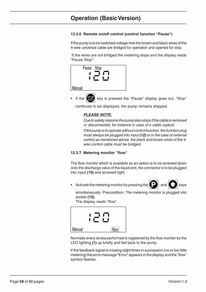
If the pump is to be switched voltage-free the brown and black wires of the4-wire universal cable are bridged for operation and opened for stop.
If the wires are not bridged the metering stops and the display reads"Pause Stop".
StopPause
Manual
• If the STOPSTART
key is pressed the "Pause" display goes out. "Stop"
continues to be displayed, the pump remains stopped.
PLEASE NOTE:Due to safety reasons the pump also stops if the cable is removedor disconnected, for instance in case of a cable rupture.If the pump is to operate without control function, the function plugmust always be plugged into input (12) or in the case of externalcontrol as mentioned above, the black and brown wires of the 4-wire control cable must be bridged.
12.3.7 Metering monitor "flow"
The flow monitor which is available as an option is to be screwed downonto the discharge valve of the liquid end, the connector is to be pluggedinto input (10) and screwed tight.
• Activate the metering monitor by pressing the P - and keys
simultaneously. Precondition: The metering monitor is plugged intosocket (10).The display reads "flow".
Manual flow
Normally every stroke performed is registered by the flow monitor by theLED lighting (1) up briefly and fed back to the pump.
If the feedback signal is missing eight times in succession (no or too littlemetering) the error message "Error" appears in the display and the "flow"symbol flashes.

Page 59 of 88 pagesVersion 1.0
Operation (Basic Version)
Error
Manual flow
If additionally the relay option "Fault annunciation relay de-energising"was selected the relay de-energises to issue the alarm or energises for"switching mode" energising. The word "Relay" appears in the display.
Error Relais
flowManual
• By simultaneously pressing the P - and key the monitoring
function can be turned off.
• By removing the function plug from the socket (10) it is automaticallyturned off.
12.3.8 Error messages - acknowledging error messages
PLEASE NOTE:Watch flashing error message on display (4)!
Check whether the function plugs (11/12) are plugged in or cableplug (10) is correctly connected!
Error message "Error Minimum"Possible cause: Lack of chemical
Remedy: • The error message confirms itself by filling up the supply tank.
Error message "Error flow"Possible cause: No or too little metering
Remedy: • Briefly pressing the P key or executing the control function
"Pause/Stop" (remote on/off)
Entire display flashesPossible cause: System error
Remedy: • Briefly pressing the P key or executing the control function
"Pause/Stop" (remote on/off)
Entire display continues to flash: • The pump must be sent back to the factory to be checked.

Page 60 of 88 pages Version 1.0
Operation (Option Version)
12.4 Overview operating scheme (option version)
Analog
Analog
mA
P
Analog
mA
P
Manual
Contact
P
P
P
Contact
Contact
P P
Faktor
Current
f
N
N
P
PContact
Mem.
Contact
< Press the key at least 2 secs
G/5b-053.1-GB
P
P
P
P
P
STOPSTOPSTART
Manual Analog Contact
f
N
STOPSTOPSTART
Operating mode
Display mode
Manual
Stop
f
N
Increase stroking rate
Decrease stroking rate
Metering monitoring off
Priming
Start pulse at contact
Error confirmation
Metering monitoring on
Pumpstops
Pumpoperates

Page 61 of 88 pagesVersion 1.0
Hour Hour
P P P
P
P
P
P
Set clock
Weekday Hour Minute
Program timer
Switch-on no.
Timer
Switch-on day
Releasing
Locking
Deleting
Sunday
Monday
Daily
P
Starting time
P
Minute
P P
P
Stop time
P
P
Minute
P
Switch-on no.
P
Releasing
Locking
G/5b-053.2-GB
P
P
2 secs
= for initial setting " - " appears at this point
= for subsequent setting the numbers "0 - 9" appear at this point
See separate operating instructions Option Timer for user description
Operation (Option Version)

Page 62 of 88 pages Version 1.0
Operation (Option Version)
12.5 Operation (option version)
12.5.1 Analog control
Analogue signals such as current signals 0/4-20 mA or voltage signalswhich can be switched over from 0-60 mV, 0-1 V and 0-10 V can be usedfor direct proportional control of the stroking rate.
WarningThe voltage of analogue control signals must be separated!
Specify whether current or voltage signal is desired using the identitycode, the reverse proportional function e.g. 20 - 4/0 mA or 60 - 0 mV,1 - 0 V, 10 - 0 V is available as a special option.
PLEASE NOTE:100% stroking rate in analogue operation corresponds to thenumber of strokes per minute laid down in "Manual" operation!If for example in "Manual" operation the stroking rate was reducedto 10 strokes/min., in the "Analog" operation at maximum inputvariable only these 10 strokes per minute can be executed anddisplayed!
Selection of the signal range:
• Stop the pump with the STOPSTART
key -
Display
Manual
Stop
f
• Press the P key for two seconds and with the key select
the following display:
Manual
Stop
Analog Contact
• Press the P key and with the key select "Analog".
!
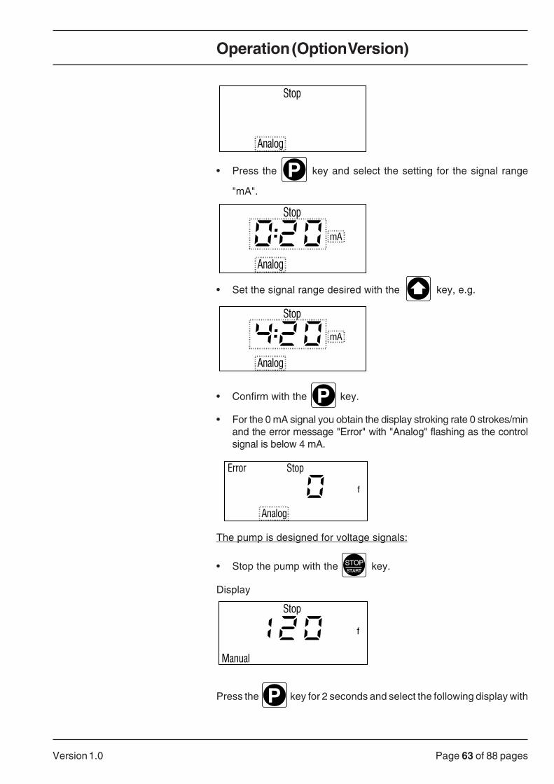
Page 63 of 88 pagesVersion 1.0
Operation (Option Version)
Stop
Analog
• Press the P key and select the setting for the signal range
"mA".
Stop
mA
Analog
• Set the signal range desired with the key, e.g.
mA
Stop
Analog
• Confirm with the P key.
• For the 0 mA signal you obtain the display stroking rate 0 strokes/minand the error message "Error" with "Analog" flashing as the controlsignal is below 4 mA.
Stop
f
Error
Analog
The pump is designed for voltage signals:
• Stop the pump with the STOPSTART
key.
Display
Manual
Stop
f
Press the P key for 2 seconds and select the following display with

Page 64 of 88 pages Version 1.0
Operation (Option Version)
the key:
Manual
Stop
Analog Contact
• Press the P key and with the key select "Analog".
Stop
Analog
• Press the P key.
Analog
V
• With the or key additionally the following ranges can be
selected:
Analog
mV
Analog
V
• Confirm the desired range with the P key.

Page 65 of 88 pagesVersion 1.0
Operation (Option Version)
Error message "Error Analog":
The advantage of a "life-zero" operation (for example of a 4-20 mA signal)is the fact that the metering pump reports the failure of this signal or if itdrops below the value set (e.g. in the event of a cable rupture) as an errore.g:
Error Relais
Analog
f
In order to acknowledge the error message at least 4 mA must be appliedat the signal current input, after this the pump starts again independentlyand the error display "Error" and the flashing "Analog" go off.
If however after an error message the metering pump should remain in the"Error/stop" mode and not continue to feed automatically from 4 mA, thecustomer must fit a suitable automatic relay to support this function.
This fault annunciation relay then takes over the alarm annunciation fromthe optional fault annunciation relay of the metering pump and switchesthe metering pump off using the control function "Pause/stop".
For releasing the metering the automatic relay must then be releasedagain and the "Pause/stop" control function must be revoked via thecontrol cable.

Page 66 of 88 pages Version 1.0
Operation (Option Version)
12.5.2 Pulse Control
When the factor smaller than 1.00 is entered a step-down results, for thefactor larger than 1.00 a step-up takes place.
Factor setting range 0.01 to 9999.
Example table:
The number of strokes executed is equal to the number of incoming pulsesx factor.
Factor Pulse Metering strokePulses (sequence) Metering strokes (sequence)
0.01 100 10.10 10 10.25 4 10.33 3.03 (33 • 3 - 1 • 4) 10.40 2.5 (2 - 3) 10.50 2 10.75 1.33 (1 - 1 - 2) 11.00 1 11.25 1 1.25 (1 - 1 - 1 - 2)1.50 1 1.5 (1 - 2)2.00 1 22.50 1 2.5 (2 - 3)25.0 1 259999 1 9999
If one does not obtain an integer result on dividing by the factor, in themicroprocessor the residual amount after the decimal point is added upand an additional stroke is executed as soon as the result reaches orexceeds the value 1.
Thus on average for injection operation the precise metering amountaccording to the factor results.
With the Pulse Control option the following functions are possible:
- Pulse step-down with factor 0.01 - 1.00
- Pulse step-up (preselection) with factor 1.00 - 9999
- Memory "Mem"
- Display of the step-down or step-up factor "N↔"
- Stroke counter device "N" (also available for Analog variant).

Page 67 of 88 pagesVersion 1.0
Operation (Option Version)
Pulse step-down/step-up:
This function enables the number of pulses received to be divided by afactor of 0.01 to 1.00 or multiplied by 1.00 to 9999.
As a result for example in connection with pulse-type water meters thepump can be tuned into a process in an optimum manner or be operatedby displaying the step-up factor "N↔" as predetermining counter.
To set:
• Press the P key approx. 2 seconds.
The display
Manual Contact
Stop
• or
N
Stop
f
• Press the or key until "Manual" and "Contact" can be
selected.
Manual Contact
Stop
• Confirm with the P key.
• Press the or key until "Contact" appears.
Manual Contact
Stop
• Confirm with the P key.

Page 68 of 88 pages Version 1.0
Operation (Option Version)
• Press the or key.
ContactMem.
Stop
The " "setting in the display enables the activation of the memory functionmemory "Mem".
• When no longer desired switch "Mem" off with the key.
Contact
Stop
• Confirm with P ,
the factor set, e.g. 1.00 is displayed.
Contact
Stop
• Pressing the or key enables for example a factor of 5 to
be set, i.e. with every incoming pulse the pump executes five strokes.
Contact
Stop
• Confirm with PDisplay "E" for external (remote) control in "Contact" operation.
Contact
Stop

Page 69 of 88 pagesVersion 1.0
Operation (Option Version)
Selection of the display functions "f", "N↔" or "N":
So that the factor "N↔" of the step-up ratio, e.g. 5.00 is always displayedor the metering strokes executed are counted by being added on (strokecounter "N") the following settings should be carried out.
Display
Contact
Stop
• Press the P key approx. 2 seconds
Manual Contact
Stop
• Press the key for display function.
N
Stop
f
• Confirm with P
f
Stop
"f" specifies the stroking rate in 0 to 120 (100) strokes per min.

Page 70 of 88 pages Version 1.0
Operation (Option Version)
• By pressing the the - key several times, "N↔" or "N" is selected.
N
Stop
Stroke counter "N" counts the strokes executed in all operating modes. Amaximum of 9999 can be counted. After that the display starts again at 1.The excess strokes are indicated by a " " in the display.
• Set display function "↔" with the key.
N
Stop
• Confirm with P
• After starting via an external contact or after briefly pressing the Pkey, for example 5 metering strokes of the stroking rate preselected in"Manual" operation are worked off and displayed subtracting.
Contact
Stop
N

Page 71 of 88 pagesVersion 1.0
Operation (Option Version)
12.5.3 Preselection operation and memory
Preselection operation
The setting previously described (pulse step-up "Contact" and "N" withfactor > 1) can also be interpreted as preselection operation.
After starting via an external contact or the P key the preselected no.
of strokes are counted down on the display. When the "1" is reached thepump stops and the display jumps back to the preselected stroking rate.
If a further start contact takes place before the strokes to be executed areexecuted, the preselected number of strokes are executed again.
If the memory function "Mem" has been activated, with every start contactthe preselected number of strokes is added.
Please note:As for the preselection operation without memory the internalmemory of the pump is not active a reset takes place whenexecuting any functions which result in a pump stopping. Thedisplay jumps back to the preselected number of strokes andmust be started again via a remote contact or by pressing the
P key.
Memory operation "Mem"
The memory function enables faster pulses than 2 per second to be savedwhich can then be worked off later as discharge strokes with the strokingrate set in "Manual" operation.
A maximum of 65535 pulses at factor 1.00 are saved. The number ofpulses which can be saved depends on the factor and results for exampleat factor 0.01 in a total of 6553500 pulses or at factor 100 in a total of 655pulses.
An error message "Error" takes place in the event of a higher number ofpulses if the memory capacity is exceeded, the "Mem" display flashes andthe pump is stopped.
Maximum pulse frequency 40 pulses/s, necessary contact duration 20ms.

Page 72 of 88 pages Version 1.0
Operation (Option Version)
12.5.4 Relay option
The relay can be designed selectively in switching mode no. 1 to no. 4(ordering specification takes place via identity code).
Only one function is always present and it is not possible to switch toanother switching mode.
Switching mode no. 1: "Fault annunciation relay de-energising"
As a collective fault for early level warning and final switch-off, meteringmonitoring, fuse and mains failure reporting as well as a system error.
Function: Relay for alarm de-energising
PLEASE NOTE:For version no. 1 care should be taken that even when the mainsis switched off the pump, the relay de-energises and an alarm isissued!
The mains supply line and the alarm annunciation should thereforebe locked with each other, if when the mains is switched off noalarm message should take place!
Switching mode no. 2: "Pacing relay energising"
For issuing a contact parallel to the metering stroke of the stroke solenoid.
Contact duration approx. 150 ms.
Switching mode no. 3: "Fault annunciation relay energising"
As an alarm relay for level early warning and final switch-off, meteringmonitoring and system error.
Function: Relay energising in the event of an alarm
Switching mode no. 4: "Timer relay energising"
The timer relay is functionally independent of the metering times set usingthe timer function (switching periods) and can be used for simultaneouslycontrolling a second metering pump or other electrical devices.
The timer relay is paced in the 3 following operating cases:
a) The timer was released and the pump meters within an activeswitching period.-> Timer relay is energised.
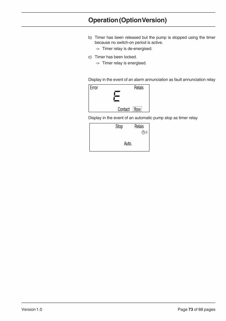
Page 73 of 88 pagesVersion 1.0
Operation (Option Version)
b) Timer has been released but the pump is stopped using the timerbecause no switch-on period is active.
-> Timer relay is de-energised.
c) Timer has been locked.
-> Timer relay is energised.
Display in the event of an alarm annunciation as fault annunciation relay
Error Relais
flowContact
Display in the event of an automatic pump stop as timer relay
Auto.
Stop Relais

Page 74 of 88 pages Version 1.0
13 Maintenance
WARNINGMetering pumps and their peripheral devices may only beserviced by trained personnel and authorised persons!
PLEASE NOTE:Service intervals: every three months, shorter intervals underheavy load (e.g. continuous operation)!
The maintenance of the gamma metering pump is limited to checking
• the liquid end screws (tightness)
• the discharge lines (tightness)
• the discharge and suction valves (tightness)
• the leakage bore at the intermediate disk (dampness can indicate adiaphragm rupture)
• that the pump is feeding correctly - for this purpose briefly operate the
pump in priming operation (simultaneously pressing the and
key).
14 Trouble shooting/eliminating errors
14.1 Errors you can eliminate yourself
PLEASE NOTE:In order to be able to eliminate small errors at any time werecommend that you always have a set of spare parts - consistingof diaphragms, valves, balls, seals and fuses!You can find the order nos. for this in our product catalogue under"Spare parts kit for gamma/5"!
WARNING:For maintenance and repair work always rinse out the liquidend first if dangerous or unknown media are used!
WARNING:When metering dangerous or unknown fluids protectiveclothing must be worn when working on the liquid end(glasses, gloves)!
WARNING:Always relieve the discharge line of pressure first beforeworking on the pump!Always empty and rinse the liquid end!Observe the safety data sheets of the metering fluid!
Maintenance/Troubleshooting/Eliminating Errors

Page 75 of 88 pagesVersion 1.0
Troubleshooting/Eliminating Errors
ATTENTION:Only set the stroke length when the pump is running and when thesetting bolt of the metering stroke is briefly relieved.
14.1.1 Pump does not prime in spite of full stroke movement andbleeding
Possible cause: Crystalline deposits due to dryed out valves
Remedy: • Remove suction hose from the supply tank and rinse the liquid end well.
• If there is no improvement the valves should be disassembled andcleaned.
• The valve insert in the suction and discharge valve can be pushed outwith a 3 mm punch.
14.1.2 Float switch does not switch the metering pump off atminimum chemical level
Possible cause: Float is blocked.
Remedy: • Remove deposits and clean float.
14.1.3 Pump does not meter although yellow display lamp (1)flashes
Possible cause: The stroke length is set to "zero" or no value is set.
Remedy: • Increase the stroke length with the adjustment knob (3).
Other possible cause: Air is trapped in the liquid end.
Remedy for SS and TT pumps: • Relieve the discharge line of pressure using the overflow or relief valve,or by releasing the discharge line at the injection valve or dischargeconnection of the pump. In doing so protective clothing (glasses,gloves) are to be worn.
• Bleed by quick priming - simultaneously press the and
keys until the suction line and liquid end are filled free of bubbles.
Remedy for NP and PP pumps: • Do not loosen the discharge line as the bleed valve is present.
• Open the bleed valve (17) by max. 1 turn anti-clockwise.
• Quick priming - simultaneously press the and keys until
the suction line and liquid end are filled free of bubbles.
• Close the bleed valve.

Page 76 of 88 pages Version 1.0
Please note:For pumps with level switch and early warning:
In this case, air can normally neither enter the pipe system nor theliquid end as the pump switches to early warning when the firstswitching point is reached: when the second switching point isreached (after a path of 30 mm) the pump switches itself off.
14.1.4 Red warning lamp (8) lights up - "Error" readout on display (4)flashes
Error message "Error minimum"Possible cause: Lack of chemicals or function plug
Remedy: • The error message acknowledges itself by filling up the supply container.
• Check whether the function plug level (11) is plugged in.
Error message "Error flow"Possible cause: No or too little metering
Remedy: • Briefly press the P key or execute the control function "Pause/
Stop" (remote on/off).
• If the error message appears again bleed the liquid end and increasethe stroke length.
Complete display flashesPossible cause: System error
Remedy: • Briefly press the P key or execute the control function "Pause/
Stop" (remote on/off)
Complete display continues to flash The pump must be sent to the factory to be checked.
> Also see chapter 15/page 82 for information about this.
Troubleshooting/Eliminating Errors

Page 77 of 88 pagesVersion 1.0
Troubleshooting/Eliminating Errors
14.1.5 Fluid is leaking at the intermediate disk
Possible cause: The liquid end is not tight at the pump diaphragm.
Remedy: • Tighten the screws (arrow) in the liquid end crosswise.
G /5b-047-D
ATTENTION:It is essential that the torques for the screws are observed!Torques for screwsM5 x 45, M5 x 60 and M5 x 70: 4.5 to 5 Nm!
PLEASE NOTE:The torque of the liquid end screws is to be checked after 24 hoursoperation!For PP pumps the torques are to be checked additionally everyquarter of a year!
• If fluid is still leaking the diaphragm has ruptured and must beexchanged
PLEASE NOTE:The pump diaphragm is a part subject to wear - its service lifedepends on counter pressure in the system operating temperaturequalities of the medium to be metered!
PLEASE NOTE:When using abrasive media the service life of the diaphragm isrestricted and the diaphragm must be checked more often!The installation of a diaphragm rupture warning is recommendedin this case!

Page 78 of 88 pages Version 1.0
Exchanging the pump diaphragm • With the pump running, set the stroke length with the revolving knob (3)to "0".
• Remove the screws (17c).
1520
ca. 5 m
m
19
G/5b-049-D
17 c
• Pull out the liquid end (19) with screws from the intermediate disk (20)and pump enclosure (15) (approx. 5 mm) until no resistance can be feltfrom the screws.
• Hold the housing (15) in your left hand and with your right handunscrew the diaphragm (20a) and the intermediate disk (20) with thescrews (17c) of the drive axle (15a) by turning the liquid end (19) to theleft with a slight jerk.
17 c
75 % L. skal; 66% L. nicht skal =50%
1520
ca. 5 m
m
19
G/5b-050-D
Troubleshooting/Eliminating Errors

Page 79 of 88 pagesVersion 1.0
• Now pull the liquid end with the screws out of the diaphragm andcompletely unscrew this from the drive axle.
• Remove the intermediate disk (20) from the enclosure (15).
• Screw on a new diaphragm (20a) to the stop of the drive axle (15a)and check the threads are smooth.
• Unscrew the diaphragm again from the drive axle.
• Replace the intermediate disk onto the enclosure again.
• Insert the diaphragm into the intermediate disk and screw on 2thread turns.
ATTENTION:Turn the diaphragm in such a way that the 4 bores of thediaphragm and intermediate disk match precisely!The drain opening of the intermediate disk must point downwards!
• Place the liquid end (suction connection must point downwards!)with screws onto the diaphragm and intermediate disk so far that theparts can still be turned (again leave approx. 5 mm distancebetween the liquid end and the intermediate disk!).
• Now turn the parts clockwise so long until the diaphragm is sittingtightly (the twist resistance of the recuperating spring can be felt).
ATTENTION:Do not overturn the diaphragm!
Troubleshooting/Eliminating Errors
1520
20a
19
G/5b-051-D
17c
15a

Page 80 of 88 pages Version 1.0
Troubleshooting/Eliminating Errors
• Set the stroke length to 100% with the knob (3), and with the meteringpump running turn the complete liquid end so long to the right until thesuction connection points downwards vertically.
• Stop the pump.
• Then tighten the 4 screws (17c) crosswise.
ATTENTION:It is essential that the torques for the screws are observed!
Torques for screws
M5 x 45, M5 x 60 and M5 x 70: 4.5 to 5 Nm!
PLEASE NOTE:The torque of the liquid end screws is to be checked after 24 hoursoperation!
For PP pumps the torques are to be checked additionally everyquarter of a year.
• With the pump running set the stroke length desired.
14.1.6 Exchanging the complete liquid end
PLEASE NOTE:Complete liquid ends are delivered with the bleed valve open!After priming and bleeding the fine bleeding screw (17a) and thebleed valve (17) must be tightened!Check that the suction and discharge valves fit firmly!
14.2 Errors which require customer service assistance
DANGER:Electrical repairs may only be carried out by trained electricians(safety regulations of the employers’ insurance associations:VBG 4 and ZH 1/11)!
DANGER:Before opening the pump pull out the mains plug or cut offthe power supply!Check that the pump is voltage-free!Also isolate relay option if fitted!During the repair work, it is essential that it is not possible forthe pump to be switched on again!
WARNING:Metering pumps may only be repaired by trained andauthorised persons!

Page 81 of 88 pagesVersion 1.0
Troubleshooting/Eliminating Errors
14.2.1 Pump does not move, yellow display light (1) does not lightup, no readout on the display (4)
Possible cause: Incorrect mains voltage is being applied.
Remedy: • Use the specified mains voltage according to the voltage specificationon the name plate.
Other possible cause: Faulty fuse
Remedy: • Have the fuse checked by an authorised customer service and ifnecessary have it exchanged.
PLEASE NOTE:Only use the correct fuses of the manufacturer!Type Littlefuse, super slow, dimensions 6.3 x 32 mmFor pump types 1602, 1006, 0613, 0417, 0230:Version 230 V -fuse 0.5 A, ATT, order no. 71.20.37.1Version 115 V -fuse 1.0 A, ATT, order no. 71.20.52.0For pump types 1605, 1310, 0813, 0423:Version 230 V -fuse 0.7 A, ATT, order no. 71.20.51.2Version 115 Vfuse 1.25 A, ATT, order no. 71.20.38.9
• If the error cannot be corrected by changing the fuse the pump mustbe checked in the factory.
> See chap. 15/page 82 for more information
14.2.2 Mains connection line (system cable) damaged
Remedy: • Have the connection line exchanged by an authorised customerservice!
PLEASE NOTE:Only use the manufacturer’s correct connection lines with Europlug.For all gamma pump types:Order no. 81.85.26.6For all other mains cables see list of spare parts!

Page 82 of 88 pages Version 1.0
Repair
15 Repair
WARNING:Metering pumps may only be repaired by trained andauthorised persons!
Customer service Inform your customer service responsible!
Or contact the ProMinent subsidiary or representativeresponsible for you.
(Addresses can be found on the back page of these operatinginstructions)!
WARNING:Pumps for radioactive media Pumps for radioactive media may not be sent.
PLEASE NOTE:Only send the metering pump back for repair once it has beencleaned and the liquid end has been rinsed!
PLEASE NOTE:The legal regulations for occupational safety - e.g. the regulationgoverning places of work, hazardous substances, the preventionof accidents and environmental protection regulations (lawgoverning waste or water resources) oblige all industrialentrepreneurs to protect their employees or people and theenvironment against damaging effects from handling hazardoussubstances!
An inspection or repair of pumps and their parts therefore onlytakes place if a correctly and completely filled in certificateconfirming the quality as being recognised as safe can besubmitted by authorised and qualified specialists of the pumpoperator!
If in spite of emptying and cleaning the pump carefully, safetymeasures are necessary, the necessary information must belisted in the certificate confirming the pump is recognised as beingsafe!
The certificate confirming the pump is recognised as being safeis a part of the inspection/repair contract.
There is a standard form at the end of these operatinginstructions for this purpose!
We reserve the right not to accept the contract due to otherreasons. Pumps which were operated with materials with aradioactive load are not accepted as a general rule!

Page 83 of 88 pagesVersion 1.0
Disposal of old parts
16 Disposal of old parts
WARNING:Never throw metering pumps in the bin (domestic refuse).Plastic and mechanical parts are special waste and must berecycled!
Abfg, AbfRestberwV Waste (old parts) is to be disposed of in an "orderly manner for thecommon good especially the protection of the environment". Thereforeold parts have to be disposed of in accordance with the (German) WasteAvoidance and Waste Management Act (Abfg) or recycled in accordancewith the (German) Waste and Residual Materials Monitoring Act(AbfRestberwV).
Taking back old parts If you should not find any appropriate collection point the ProMinentsubsidiary or representative responsible for you will take back your oldparts for a small fee (addresses can be found at the back of these operatinginstructions)!

Page 84 of 88 pages Version 1.0
Appendix/Cross Section of Pump
This picture shows the G/5b 0417PP1 pump
15 Enclosure17 Bleed valve
17a Fine bleed screw
17b Star handle
18 Bypass hose nozzle
19 Liquid end with suction and discharge connection
20 Intermediate disk with leakage bore
20a Pump diaphragm with steel core and PTFE layer
21a Gripper ring
21b Hose nozzle
22 Pocket for short operating instructions
23 Gasket
24 Short stroke solenoid
24a Pressure piece
25 Fuse
26 Electronic control with microprocessor
G/5b-052-D

Page 85 of 88 pagesVersion 1.0
Warranty Application
Please complete in full !
Warranty application for metering pumps No.
Company ............................................................................... Tel. no.: ...................... Date: ..............
Address: ................................................................................................................................................
Clerk (customer): ..................................................................................................................................
Order no.: .............................................................................. Delivery date: ......................................
Pump type/identity code: ......................................................................... Serial no.: ............................................
Short description of fault: ..................................................................................................................
..............................................................................................................................................................
..............................................................................................................................................................
..............................................................................................................................................................
Type of fault:
1 Mechanical fault 2 Electrical fault
❒ Unusual wear ❒ Connections such as plugs or cables loose
❒ Parts subject to wear ❒ Operating elements (e.g. switches)
❒ Rupture/other damage ❒ Control
❒ Corrosion
❒ Damage during transport
3 Leakage 4 No or poor capacity
❒ Connections ❒ Diaphragm defective
❒ Liquid end ❒ Other
Application conditions of ProMinent pumps:
Location/system description: ..................................................................................................
Pump accessories used: ..................................................................................................
..........................................................................................................................................................
..........................................................................................................................................................
Commissioning (date): ..................................................................................................
Running time (approx. operating hours): ..........................................................................................
Please specify set-up data and enclose sketch of the system.
Please copy and send in with the pump.
If the pump breaks down within the warranty period please clean the pump and send it back alongwith the fully completed warranty application.
▼

Page 86 of 88 pages Version 1.0
Customer:
Project no: Date: ____________________ ❒ Sketch enclosed: _______________________
Metering pump Type - ____________________________
Capacity l/h ____________________________
Stroking rate s/min. ____________________________
Stroke length % ____________________________
Valve spring pressure suction side bar ____________________________
Valve spring pressure discharge side bar ____________________________
Medium
Designation, concentration % ______________ / ____________
Share of solids/size of particle %/mm ______________ / ____________
Material solid/hardness Mohs ____________________________
Dynamic viscosity mPas (cP) ____________________________
Density kg/m3 ____________________________
Vapour pressure at operating temperaturebar/°C ______________ / ____________
System suction side
Pressure in suction tank ____________________________
Nominal width suction line DN/mm ______________ / ____________
Suction lift min/max m ______________ / ____________
Weir height min./max. m ______________ / ____________
Length suction line m ____________________________
Number of angles/valves ____________________________
Accumulator ❒ Bubble tank __________________ l
❒ Accumulator__________________ l
System discharge side
Static system pressure min/max. bar ______________ / ____________
Nominal width discharge line DN/mm ____________________________
Length discharge line m ____________________________
Delivery head m ____________________________
Number angles/valves ____________________________
Accumulator ❒ Bubble tank __________________ l
❒ Accumulator_________________ l.
Installation Data

Page 87 of 88 pagesVersion 1.0
Please copy and send in with the pump!
Safety certificate
We herewith certify that the enclosed device
Type: ............................................................................................................
Serial-no.: ............................................................................................................
is free of
- chemical
- biological or
- radioactive substances
which are a health hazard.
The device has been thoroughly cleaned before being dispatched.
Date/signature Company stamp
Safety certificate

Page 88 of 88 pages Version 1.0