Embed Size (px)
Citation preview
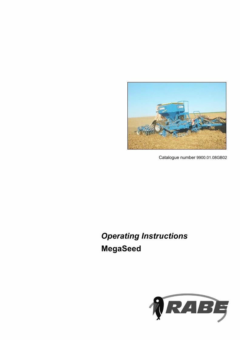
MegaSeedOperating Instructions
Catalogue number 9900.01.08GB02

3 07.2003
Read
and
follo
w th
e sa
fety
instru
ction
s!
3 07.2003
Before operating the seed drill for the first time, please read carefully through these operating instructions and the safety precautions (”For your own safety”) and ensure that they are observed.
Ensure that the operators are properly qualified, trained in its use and everyday maintenance, and familiar with the hazards. Make sure that other users are supplied with the safety precautions.
Ensure that all applicable accident prevention regulations are observed, along with other generally recognized safety procedures and any legislation that may apply with respect to road traffic and to health and safety in the workplace.
Observe the warning labels at all times! (DIN 4844-W9)
Instructions in this manual which are marked with this symbol, and its presenceon the unit, warn of danger (for explanation see appendix).
The ‘Beware’ symbol indicates safety instructions which, if not observed, may cause danger to the unit and its operation.
The ‘Note’ symbol indicates machine-specific instructions which should be followed for trouble-free operation of the unit.
Loss of warranty
This trailed seed drill is designed and built exclusively for standard agricultural use. Use for any other purpose will be regarded as unauthorized operation and no liability whatsoever will be accepted for any damage or injury that may occur as a result. The term ”authorized operation” also covers the full observance of all operating, maintenance and servicing specifications and the exclusive use of original spare parts. The use of non-original accessories, spares and/or consumables that do not carry specific approval from RABE shall void all warranty liabilities.
We accept no liability for damage, loss or injury resulting from the carrying out of unauthorized repairs and/or modifications to the unit nor from failure to supervise its use.
Delivery claims (transit damage, missing parts) should be made immediately and in writing.
Warranty claims, warranty conditions and our liability exclusions are based on our general terms of delivery.
MegaSeed
Operating instructions
4Subject to technical change without notice 5Subject to technical change without notice07.2003 07.2003
Table of contents Page
Description of unit 5Machine data 6Safety precautions 8Commissioning and use 91. Connection 101.1 Coupling the unit 101.2 Brakes 101.3 Electrical connections 101.4 Hydraulic connections 102. Laying up the unit 112.1 Disconnecting brakes 112.2 Hydraulic connections 112.3 Electrical connections 113. Preparation for transport 123.1 Unit 123.2 Rear Harrow 123.3 Marker arms and ground wheel 123.4 Retraction of coulter bar and tilling tools/rollers 123.5 Safety 134. Conversion to operational mode 145. Commissioning and set-up 145.1 Soil preparation 145.1.1 Turbo tiller 145.1.2 Mulch disc unit 145.1.3 Harrow tines 145.1.4 Front tine levelling board and wheel mark eradicators 145.2 Rollers 155.2.1 Toothed packer roller 155.3 Coulter bar 155.3.1 Setting the coulter pressure 155.3.2 Setting the sowing depth/pressure roller 155.4 Rear harrow 165.5 Marker arms 165.6 Sowing and metering 175.6.1 Calibration 185.7 Tramline marking 195.8 Radar 195.9 Power supply 196. Fan speed 207. Recommended metering settings on Rabe pneumatic seed drills with hydraulic fan drive 217.1 Exchanging metering wheels on pneumatic seed drills 228. Distributor head/tramline 239. Checking sowing precision on seed drills with electrically driven metering wheel 249.1 Tips for use 2410 Maintenance 2510.1 Fuses 2610.2 Faults and their resolution 2711 Transport precautions 3012 Positioning of warning symbols on the unit 31
4Subject to technical change without notice 5Subject to technical change without notice07.2003 07.2003
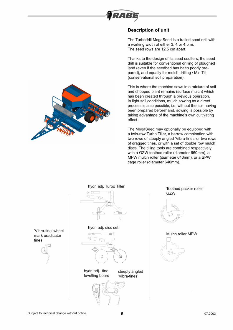
Description of unit
The Turbodrill MegaSeed is a trailed seed drill with a working width of either 3, 4 or 4.5 m.The seed rows are 12.5 cm apart.
Thanks to the design of its seed coulters, the seed drill is suitable for conventional drilling of ploughed land (even if the seedbed has been poorly pre-pared), and equally for mulch drilling / Min Till (conservational soil preparation).
This is where the machine sows in a mixture of soil and chopped plant remains (surface mulch) which has been created through a previous operation.In light soil conditions, mulch sowing as a direct process is also possible, i.e. without the soil having been prepared beforehand, sowing is possible by taking advantage of the machine’s own cultivating effect.
The MegaSeed may optionally be equipped with a twin-row Turbo Tiller, a harrow combination with two rows of steeply angled ‘Vibra-tines’ or two rows of dragged tines, or with a set of double row mulch discs. The tilling tools are combined respectively with a GZW toothed roller (diameter 660mm), a MPW mulch roller (diameter 640mm), or a SPW cage roller (diameter 640mm).
’Vibra-tine’ wheel mark eradicator tines
hydr. adj. Turbo Tiller
hydr. adj. disc set
hydr. adj. tine levelling board
Toothed packer roller GZW
Mulch roller MPW
steeply angled ‘Vibra-tines’
6Subject to technical change without notice 7Subject to technical change without notice07.2003 07.2003
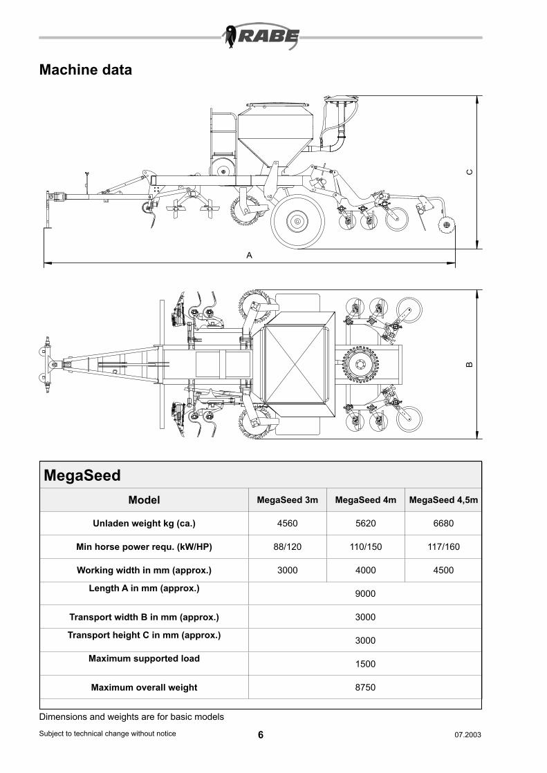
Machine data
Dimensions and weights are for basic models
MegaSeedModel MegaSeed 3m MegaSeed 4m MegaSeed 4,5m
Unladen weight kg (ca.) 4560 5620 6680
Min horse power requ. (kW/HP) 88/120 110/150 117/160
Working width in mm (approx.) 3000 4000 4500
Length A in mm (approx.) 9000
Transport width B in mm (approx.) 3000
Transport height C in mm (approx.) 3000
Maximum supported load 1500
Maximum overall weight 8750
A
BC

6Subject to technical change without notice 7Subject to technical change without notice07.2003 07.2003
Machine data
Noise level for driver when machine is running is less than 70dB(A)
MegaSeedBasic model MegaSeed 3m MegaSeed 4m MegaSeed 4,5m
Seed hopper content 2300 litres
Number of rows (row spacing=125mm) 24 32 36
Tyres (low pressure) 600/50-22.5
Brake system Air or oil brakes
Seed distributor pneumatic
Metering drive Electronically controlled electric motor
Fan drive Blade wheel blower with hydraulic motor
Hitching Lower links category III N (narrow) or drawbar hitch (pin hole dia 41 mm)
Hydr. spool valves required 2 x double acting, 1 x single acting, 1 x unpressurised return pipe
Hydraulic pressure 200 bar maximum
Control/monitoring system electronic
Working speed Up to 15 km/h
Speed on public roads 25 or 40 km/h** depending on traffic permit
8Subject to technical change without notice 9Subject to technical change without notice07.2003 07.2003
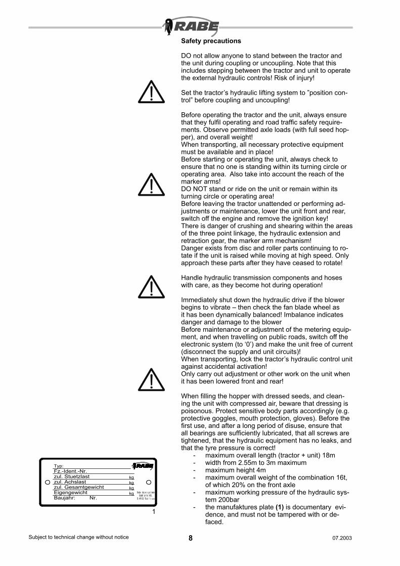
Safety precautions
DO not allow anyone to stand between the tractor and the unit during coupling or uncoupling. Note that this includes stepping between the tractor and unit to operate the external hydraulic controls! Risk of injury!
Set the tractor’s hydraulic lifting system to ”position con-trol” before coupling and uncoupling!
Before operating the tractor and the unit, always ensure that they fulfil operating and road traffic safety require-ments. Observe permitted axle loads (with full seed hop-per), and overall weight!When transporting, all necessary protective equipment must be available and in place!Before starting or operating the unit, always check to ensure that no one is standing within its turning circle or operating area. Also take into account the reach of the marker arms!DO NOT stand or ride on the unit or remain within its turning circle or operating area!Before leaving the tractor unattended or performing ad-justments or maintenance, lower the unit front and rear, switch off the engine and remove the ignition key!There is danger of crushing and shearing within the areas of the three point linkage, the hydraulic extension and retraction gear, the marker arm mechanism!Danger exists from disc and roller parts continuing to ro-tate if the unit is raised while moving at high speed. Only approach these parts after they have ceased to rotate!
Handle hydraulic transmission components and hoses with care, as they become hot during operation!
Immediately shut down the hydraulic drive if the blower begins to vibrate – then check the fan blade wheel as it has been dynamically balanced! Imbalance indicates danger and damage to the blowerBefore maintenance or adjustment of the metering equip-ment, and when travelling on public roads, switch off the electronic system (to ‘0’) and make the unit free of current (disconnect the supply and unit circuits)!When transporting, lock the tractor’s hydraulic control unit against accidental activation!Only carry out adjustment or other work on the unit when it has been lowered front and rear!
When filling the hopper with dressed seeds, and clean-ing the unit with compressed air, beware that dressing is poisonous. Protect sensitive body parts accordingly (e.g. protective goggles, mouth protection, gloves). Before the first use, and after a long period of disuse, ensure that all bearings are sufficiently lubricated, that all screws are tightened, that the hydraulic equipment has no leaks, and that the tyre pressure is correct!
- maximum overall length (tractor + unit) 18m- width from 2.55m to 3m maximum- maximum height 4m- maximum overall weight of the combination 16t,
of which 20% on the front axle- maximum working pressure of the hydraulic sys-
tem 200bar- the manufaktures plate (1) is documentary evi-
dence, and must not be tampered with or de-faced.
1
Fz.-Ident.-Nr.zul. Stuetzlast kg
kgkgkg
zul. Gesamtgewicht
Typ:
Baujahr: Nr.
zul. Achslast
Eigengewicht
8Subject to technical change without notice 9Subject to technical change without notice07.2003 07.2003
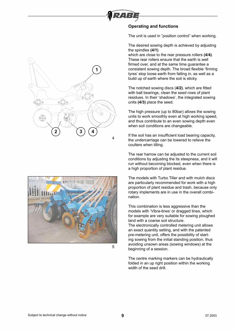
Operating and functions
The unit is used in ”position control” when working.
The desired sowing depth is achieved by adjusting the spindles (4/1) which are close to the rear pressure rollers (4/4).These rear rollers ensure that the earth is well firmed over, and at the same time guarantee a consistent sowing depth. The broad flexible ‘firming tyres’ stop loose earth from falling in, as well as a build up of earth where the soil is sticky.
The notched sowing discs (4/2), which are fitted with ball bearings, clean the seed rows of plant residues. In their ‘shadows’, the integrated sowing units (4/3) place the seed.
The high pressure (up to 80bar) allows the sowing units to work smoothly even at high working speed, and thus contribute to an even sowing depth even when soil conditions are changeable.
If the soil has an insufficient load bearing capacity, the undercarriage can be lowered to relieve the coulters when tilling.
The rear harrow can be adjusted to the current soil conditions by adjusting the its steepness, and it will run without becoming blocked, even when there is a high proportion of plant residue.
The models with Turbo Tiller and with mulch discs are particularly recommended for work with a high proportion of plant residue and trash, because only rotary implements are in use in the overall combi-nation.
This combination is less aggressive than the models with ‘Vibra-tines’ or dragged tines, which for example are very suitable for sowing ploughed land with a coarse soil structure.The electronically controlled metering unit allows an exact quantity setting, and with the patented pre-metering unit, offers the possibility of start-ing sowing from the initial standing position, thus avoiding unsown areas (sowing windows) at the beginning of a session.
The centre marking markers can be hydraulically folded in an up right position within the working width of the seed drill.
4
5
1
2 3 4
10Subject to technical change without notice 11Subject to technical change without notice07.2003 07.2003
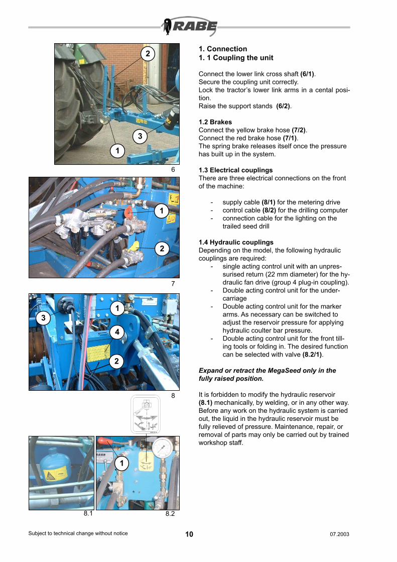
1. Connection1. 1 Coupling the unit
Connect the lower link cross shaft (6/1).Secure the coupling unit correctly.Lock the tractor’s lower link arms in a cental posi-tion.Raise the support stands (6/2).
1.2 BrakesConnect the yellow brake hose (7/2).Connect the red brake hose (7/1).The spring brake releases itself once the pressure has built up in the system.
1.3 Electrical couplingsThere are three electrical connections on the front of the machine:
- supply cable (8/1) for the metering drive- control cable (8/2) for the drilling computer- connection cable for the lighting on the
trailed seed drill
1.4 Hydraulic couplingsDepending on the model, the following hydraulic couplings are required:
- single acting control unit with an unpres-surised return (22 mm diameter) for the hy-draulic fan drive (group 4 plug-in coupling).
- Double acting control unit for the under-carriage
- Double acting control unit for the marker arms. As necessary can be switched to adjust the reservoir pressure for applying hydraulic coulter bar pressure.
- Double acting control unit for the front till-ing tools or folding in. The desired function can be selected with valve (8.2/1).
Expand or retract the MegaSeed only in the fully raised position.
It is forbidden to modify the hydraulic reservoir (8.1) mechanically, by welding, or in any other way. Before any work on the hydraulic system is carried out, the liquid in the hydraulic reservoir must be fully relieved of pressure. Maintenance, repair, or removal of parts may only be carried out by trained workshop staff.
6
7
8
8.1 8.2
9998.02.90
1
2
1
2
3
13
2
4
1
10Subject to technical change without notice 11Subject to technical change without notice07.2003 07.2003
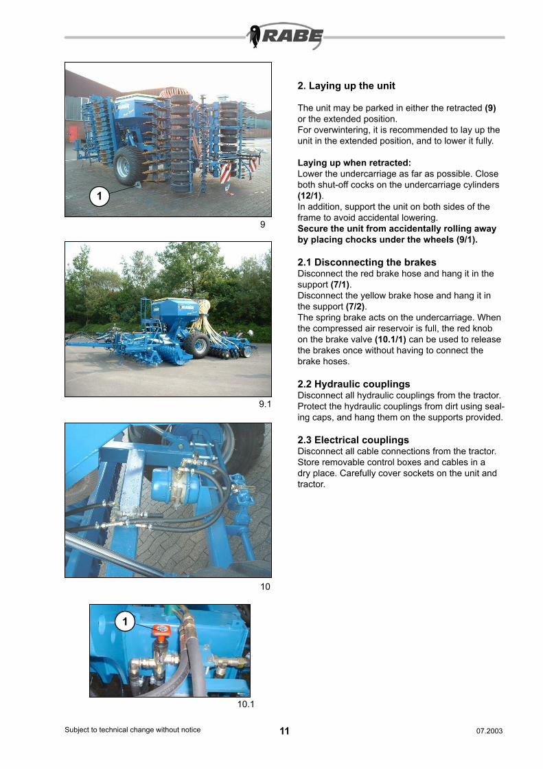
2. Laying up the unit
The unit may be parked in either the retracted (9) or the extended position.For overwintering, it is recommended to lay up the unit in the extended position, and to lower it fully.
Laying up when retracted:Lower the undercarriage as far as possible. Close both shut-off cocks on the undercarriage cylinders (12/1).In addition, support the unit on both sides of the frame to avoid accidental lowering.Secure the unit from accidentally rolling away by placing chocks under the wheels (9/1).
2.1 Disconnecting the brakesDisconnect the red brake hose and hang it in the support (7/1).Disconnect the yellow brake hose and hang it in the support (7/2).The spring brake acts on the undercarriage. When the compressed air reservoir is full, the red knob on the brake valve (10.1/1) can be used to release the brakes once without having to connect the brake hoses.
2.2 Hydraulic couplingsDisconnect all hydraulic couplings from the tractor. Protect the hydraulic couplings from dirt using seal-ing caps, and hang them on the supports provided.
2.3 Electrical couplingsDisconnect all cable connections from the tractor. Store removable control boxes and cables in a dry place. Carefully cover sockets on the unit and tractor.
9
9.1
10
10.1
1
1
12Subject to technical change without notice 13Subject to technical change without notice07.2003 07.2003
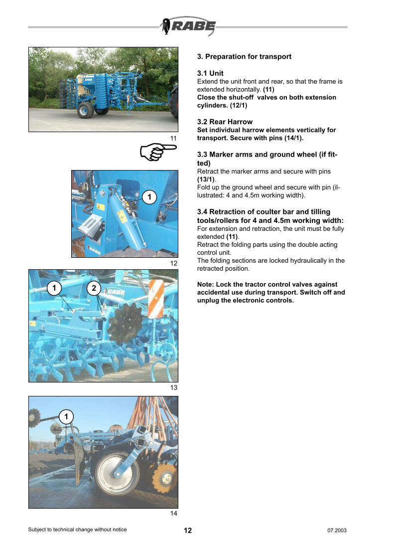
3. Preparation for transport
3.1 UnitExtend the unit front and rear, so that the frame is extended horizontally. (11)Close the shut-off valves on both extension cylinders. (12/1)
3.2 Rear HarrowSet individual harrow elements vertically for transport. Secure with pins (14/1).
3.3 Marker arms and ground wheel (if fit-ted)Retract the marker arms and secure with pins (13/1). Fold up the ground wheel and secure with pin (il-lustrated: 4 and 4.5m working width).
3.4 Retraction of coulter bar and tilling tools/rollers for 4 and 4.5m working width:For extension and retraction, the unit must be fully extended (11).Retract the folding parts using the double acting control unit.The folding sections are locked hydraulically in the retracted position.
Note: Lock the tractor control valves against accidental use during transport. Switch off and unplug the electronic controls.
11
12
13
14
1
1 2
1
12Subject to technical change without notice 13Subject to technical change without notice07.2003 07.2003
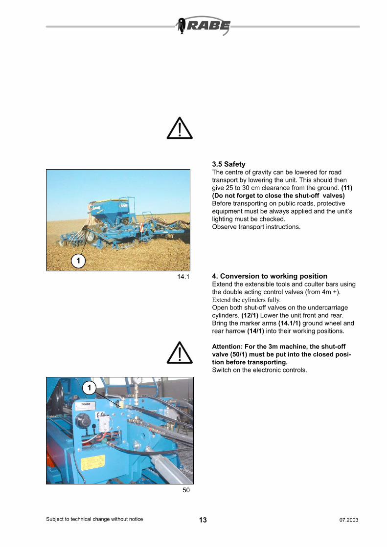
3.5 SafetyThe centre of gravity can be lowered for road transport by lowering the unit. This should then give 25 to 30 cm clearance from the ground. (11)(Do not forget to close the shut-off valves)Before transporting on public roads, protective equipment must be always applied and the unit’s lighting must be checked.Observe transport instructions.
14.1 4. Conversion to working positionExtend the extensible tools and coulter bars using the double acting control valves (from 4m +).Extend the cylinders fully.Open both shut-off valves on the undercarriage cylinders. (12/1) Lower the unit front and rear.Bring the marker arms (14.1/1) ground wheel and rear harrow (14/1) into their working positions.
Attention: For the 3m machine, the shut-off valve (50/1) must be put into the closed posi-tion before transporting.Switch on the electronic controls.
50
1
1
14Subject to technical change without notice 15Subject to technical change without notice07.2003 07.2003
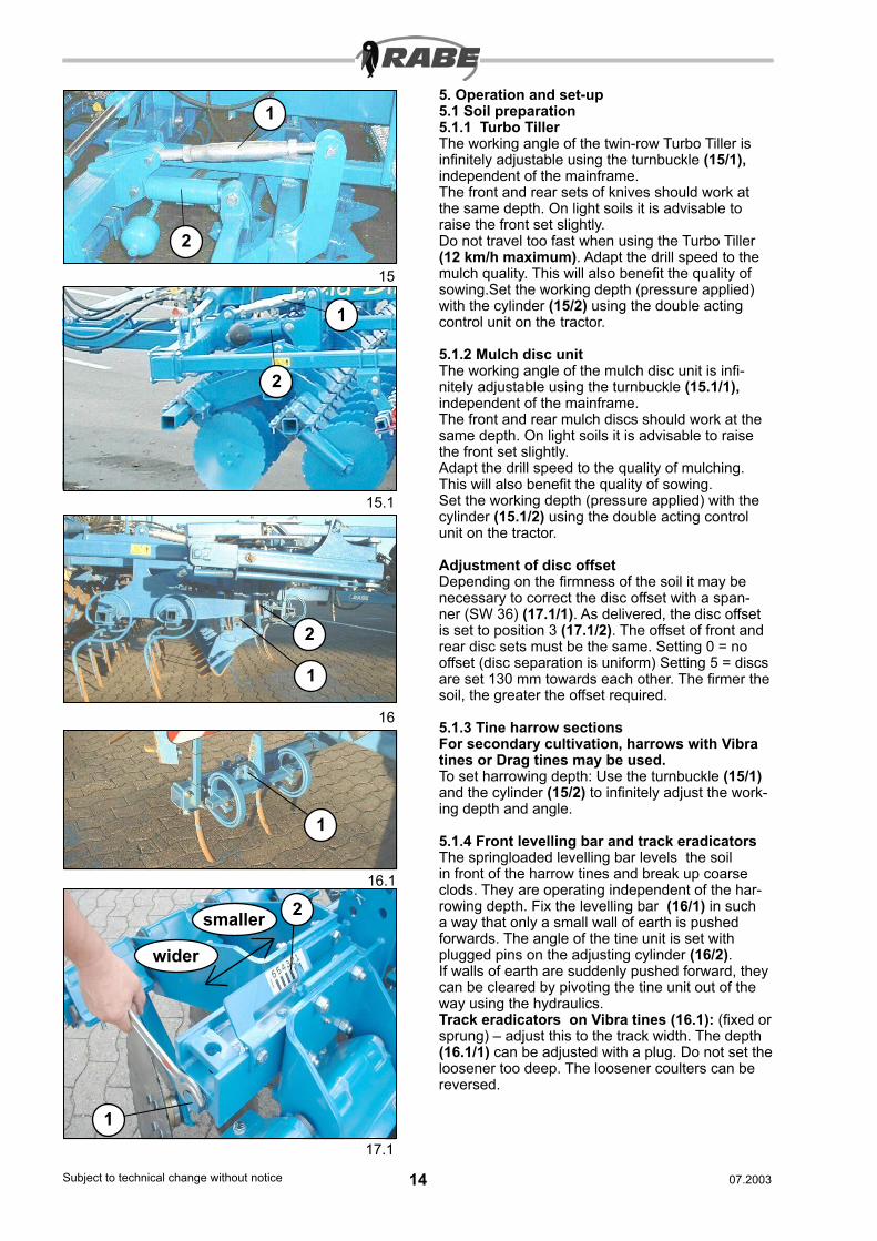
5. Operation and set-up5.1 Soil preparation5.1.1 Turbo TillerThe working angle of the twin-row Turbo Tiller is infinitely adjustable using the turnbuckle (15/1), independent of the mainframe.The front and rear sets of knives should work at the same depth. On light soils it is advisable to raise the front set slightly.Do not travel too fast when using the Turbo Tiller (12 km/h maximum). Adapt the drill speed to the mulch quality. This will also benefit the quality of sowing.Set the working depth (pressure applied) with the cylinder (15/2) using the double acting control unit on the tractor.
5.1.2 Mulch disc unitThe working angle of the mulch disc unit is infi-nitely adjustable using the turnbuckle (15.1/1), independent of the mainframe.The front and rear mulch discs should work at the same depth. On light soils it is advisable to raise the front set slightly.Adapt the drill speed to the quality of mulching. This will also benefit the quality of sowing.Set the working depth (pressure applied) with the cylinder (15.1/2) using the double acting control unit on the tractor.
Adjustment of disc offsetDepending on the firmness of the soil it may be necessary to correct the disc offset with a span-ner (SW 36) (17.1/1). As delivered, the disc offset is set to position 3 (17.1/2). The offset of front and rear disc sets must be the same. Setting 0 = no offset (disc separation is uniform) Setting 5 = discs are set 130 mm towards each other. The firmer the soil, the greater the offset required.
5.1.3 Tine harrow sectionsFor secondary cultivation, harrows with Vibra tines or Drag tines may be used.To set harrowing depth: Use the turnbuckle (15/1) and the cylinder (15/2) to infinitely adjust the work-ing depth and angle.
5.1.4 Front levelling bar and track eradicatorsThe springloaded levelling bar levels the soil in front of the harrow tines and break up coarse clods. They are operating independent of the har-rowing depth. Fix the levelling bar (16/1) in such a way that only a small wall of earth is pushed forwards. The angle of the tine unit is set with plugged pins on the adjusting cylinder (16/2).If walls of earth are suddenly pushed forward, they can be cleared by pivoting the tine unit out of the way using the hydraulics.Track eradicators on Vibra tines (16.1): (fixed or sprung) – adjust this to the track width. The depth (16.1/1) can be adjusted with a plug. Do not set the loosener too deep. The loosener coulters can be reversed.
15
16
16.1
15.1
2
1
2
1
2
1
1
17.1
1
2
wider
smaller

14Subject to technical change without notice 15Subject to technical change without notice07.2003 07.2003
Mounted unit Lower the unit until it is about 5 cm from the ground, and bring the front right and rear left outer disc units (17.2/1) into the working position. Secure the disc unit with locking pin (17.2/2).
5.2 Rollers5.2.1 Toothed packer rollerRe-adjust the scraper (17/1) regularly. Bring the scraper up to the roller until it makes light con-tact. When tightening up the nuts, ensure that the scraper makes contact along its whole length.
Use scrapers with extra hard coatings (24/1) and fit them so that the coating is upwards relative to the roller casing, and at a distance of about 2mm from the roller.The toothed packer roller can be kept clean by washing and protecting from corrosion each time it is used. If soil dries onto the roller casing, this will slow down the roller.
5.3 Coulter bar5.3.1 Setting the coulter pressureThe coulter pressure is effectively fixed. It depends on that portion of the weight of the unit which is transferred to the various knives and rollers. The coulter elements, mounted from a parallelogram, can displace themselves upwards against two cylinders which are under gas pressure. Loading of the coulter bars is carried out once before starting work. The recommended setting is 80 to 100bar. The individual coulter discs are fitted in sprung rubber elements.
5.3.2 Setting the sowing depth/press rollerSet the coulter bars horizontally using the turn-buckle (19/2). Set the desired sowing depth us-ing the pressure rollers – adjustment spindle (19, 19.1). If the spindle is shortend, the sowing depth is deeper (19.1/1). If the spindle is lengthened, the sowing depth is shallower (19/1).
Ensure that the adjustments on the press roll-ers are also the same on the foldable exten-sions!
… for ‘normal’ sowing depth , set the pressure roll-ers in the yard on a level platform to the same level as the discs (about 38 on the scale (19.2)).
If necessary, once working in the field, correct the sowing depth by adjusting the spindle length.
17
19
19.1
19.2
1
2mm
1
1
2
9998.09.01 9998.09.02
3
17.2
2 1
16Subject to technical change without notice 17Subject to technical change without notice07.2003 07.2003
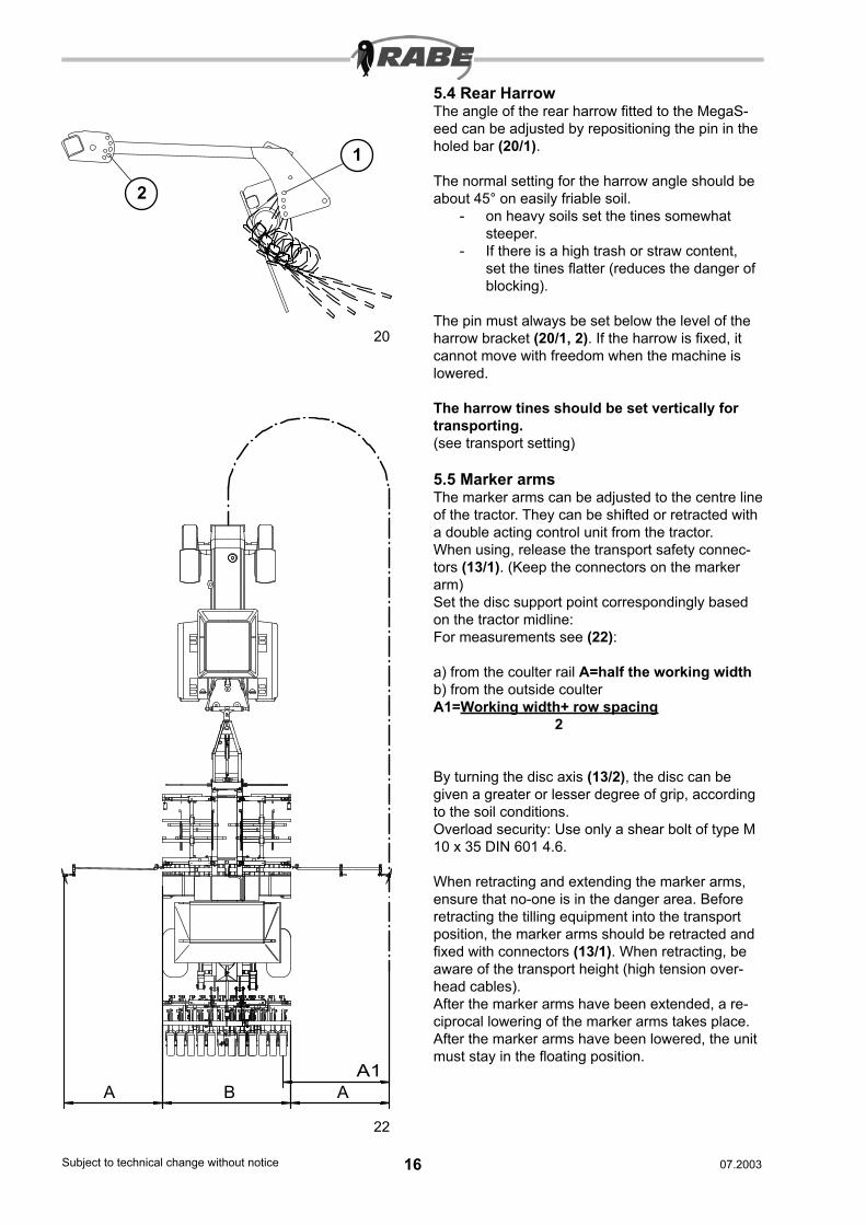
5.4 Rear HarrowThe angle of the rear harrow fitted to the MegaS-eed can be adjusted by repositioning the pin in the holed bar (20/1).
The normal setting for the harrow angle should be about 45° on easily friable soil.
- on heavy soils set the tines somewhat steeper.
- If there is a high trash or straw content, set the tines flatter (reduces the danger of blocking).
The pin must always be set below the level of the harrow bracket (20/1, 2). If the harrow is fixed, it cannot move with freedom when the machine is lowered.
The harrow tines should be set vertically for transporting.(see transport setting)
5.5 Marker armsThe marker arms can be adjusted to the centre line of the tractor. They can be shifted or retracted with a double acting control unit from the tractor.When using, release the transport safety connec-tors (13/1). (Keep the connectors on the marker arm)Set the disc support point correspondingly based on the tractor midline:For measurements see (22):
a) from the coulter rail A=half the working widthb) from the outside coulter A1=Working width+ row spacing 2
By turning the disc axis (13/2), the disc can be given a greater or lesser degree of grip, according to the soil conditions.Overload security: Use only a shear bolt of type M 10 x 35 DIN 601 4.6.
When retracting and extending the marker arms, ensure that no-one is in the danger area. Before retracting the tilling equipment into the transport position, the marker arms should be retracted and fixed with connectors (13/1). When retracting, be aware of the transport height (high tension over-head cables).After the marker arms have been extended, a re-ciprocal lowering of the marker arms takes place.After the marker arms have been lowered, the unit must stay in the floating position.
20
22
1
A BA1
A
2
16Subject to technical change without notice 17Subject to technical change without notice07.2003 07.2003
5.6 Sowing and metering
Metering unit
The metering unit is driven by an electronically controlled electric motor. The sowing rate is adjust-ed by changing the speed of rotation or by setting the metering wheel.
Settings to be borne in mind1. Metering wheel selection2. Bottom flap3. Calibration flap4. Agitation shaft
1. Metering wheel setting
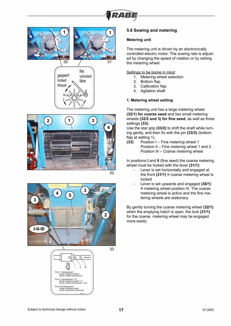
The metering unit has a large metering wheel (32/1) for coarse seed and two small metering wheels (32/2 and 3) for fine seed, as well as three settings (33):Use the star grip (33/2) to shift the shaft while turn-ing gently, and then fix with the pin (33/3) (bottom flap at setting 1). (33) Position I – Fine metering wheel 1 Position II – Fine metering wheel 1 and 2 Position III – Coarse metering wheel
In positions I and II (fine seed) the coarse metering wheel must be locked with the lever (31/1):
- Lever is set horizontally and engaged at the front (31/1) = coarse metering wheel is locked
- Lever is set upwards and engaged (30/1) = metering wheel position III. The coarse metering wheel is active and the fine me-tering wheels are stationary.
By gently turning the coarse metering wheel (32/1) when the emptying hatch is open, the lock (31/1) for the coarse metering wheel may be engaged more easily.
I II III
Pos.I Feindosierrad 1 Small metering wheel 1 Roue à petite cannelures 1
Pos.II Feindosierrad 1+2 Small metering wheel 1+2 Roue à petite cannelures 1 et 2
Pos.III Grobdosierrad Large metering wheel Roue à grosses cannelures
9998.01.18
gesperrtlockedbloqué
freiunlockedlibre
30 31
32
33
1 32
11
4
6- 1
3
2
34 5
I-II-III
18Subject to technical change without notice 19Subject to technical change without notice07.2003 07.2003
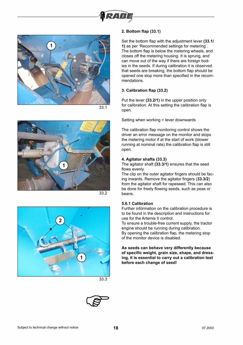
2. Bottom flap (33.1)
Set the bottom flap with the adjustment lever (33.1/1) as per ‘Recommended settings for metering’. The bottom flap is below the metering wheels, and closes off the metering housing. It is sprung, and can move out of the way if there are foreign bod-ies in the seeds. If during calibration it is observed that seeds are breaking, the bottom flap should be opened one stop more than specified in the recom-mendations.
3. Calibration flap (33.2)
Put the lever (33.2/1) in the upper position only for calibration. At this setting the calibration flap is open.
Setting when working = lever downwards
The calibration flap monitoring control shows the driver an error message on the monitor and stops the metering motor if at the start of work (blower running at nominal rate) the calibration flap is still open.
4. Agitator shafts (33.3)The agitator shaft (33.3/1) ensures that the seed flows evenly.The clip on the outer agitator fingers should be fac-ing inwards. Remove the agitator fingers (33.3/2) from the agitator shaft for rapeseed. This can also be done for freely flowing seeds, such as peas or beans.
5.6.1 CalibrationFurther information on the calibration procedure is to be found in the description and instructions for use for the Artemis II control.To ensure a trouble-free current supply, the tractor engine should be running during calibration.By opening the calibration flap, the metering stop of the monitor device is disabled.
As seeds can behave very differently because of specific weight, grain size, shape, and dress-ing, it is essential to carry out a calibration test before each change of seed!
2
1
1
33.1
33.2
33.3
1
18Subject to technical change without notice 19Subject to technical change without notice07.2003 07.2003
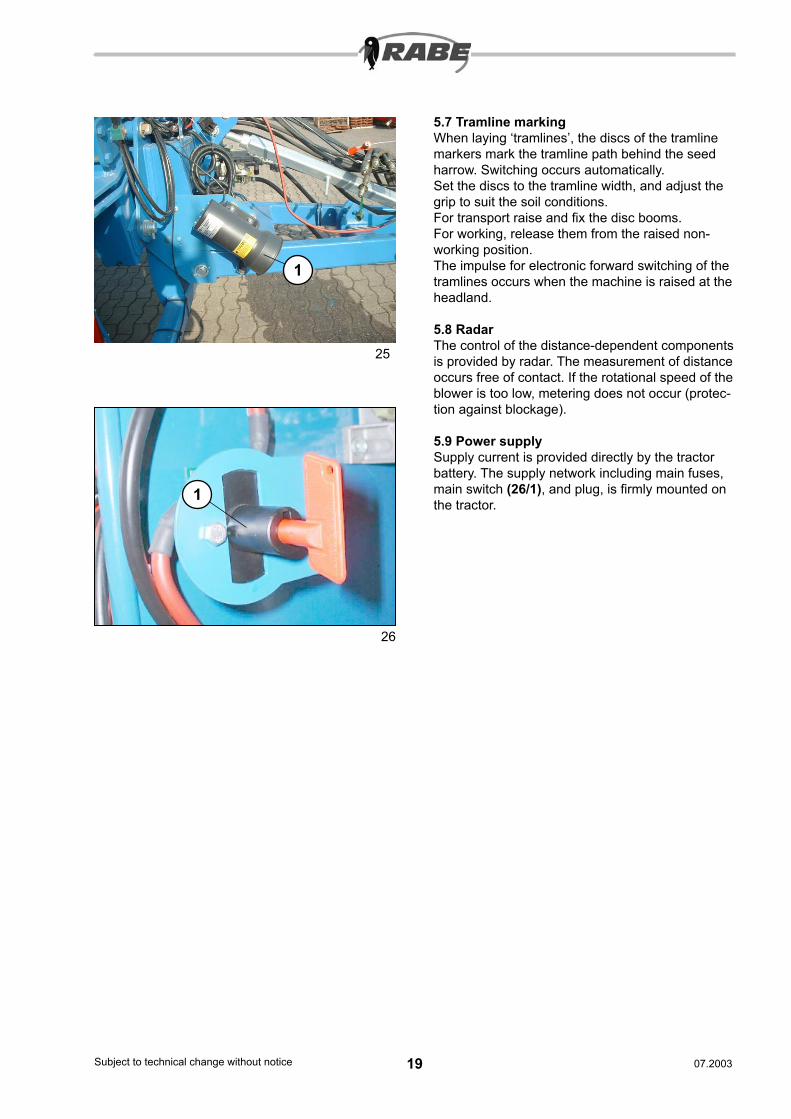
5.7 Tramline markingWhen laying ‘tramlines’, the discs of the tramline markers mark the tramline path behind the seed harrow. Switching occurs automatically.Set the discs to the tramline width, and adjust the grip to suit the soil conditions.For transport raise and fix the disc booms.For working, release them from the raised non-working position.The impulse for electronic forward switching of the tramlines occurs when the machine is raised at the headland.
5.8 RadarThe control of the distance-dependent components is provided by radar. The measurement of distance occurs free of contact. If the rotational speed of the blower is too low, metering does not occur (protec-tion against blockage).
5.9 Power supplySupply current is provided directly by the tractor battery. The supply network including main fuses, main switch (26/1), and plug, is firmly mounted on the tractor.
26
1
25
1
20Subject to technical change without notice 21Subject to technical change without notice07.2003 07.2003
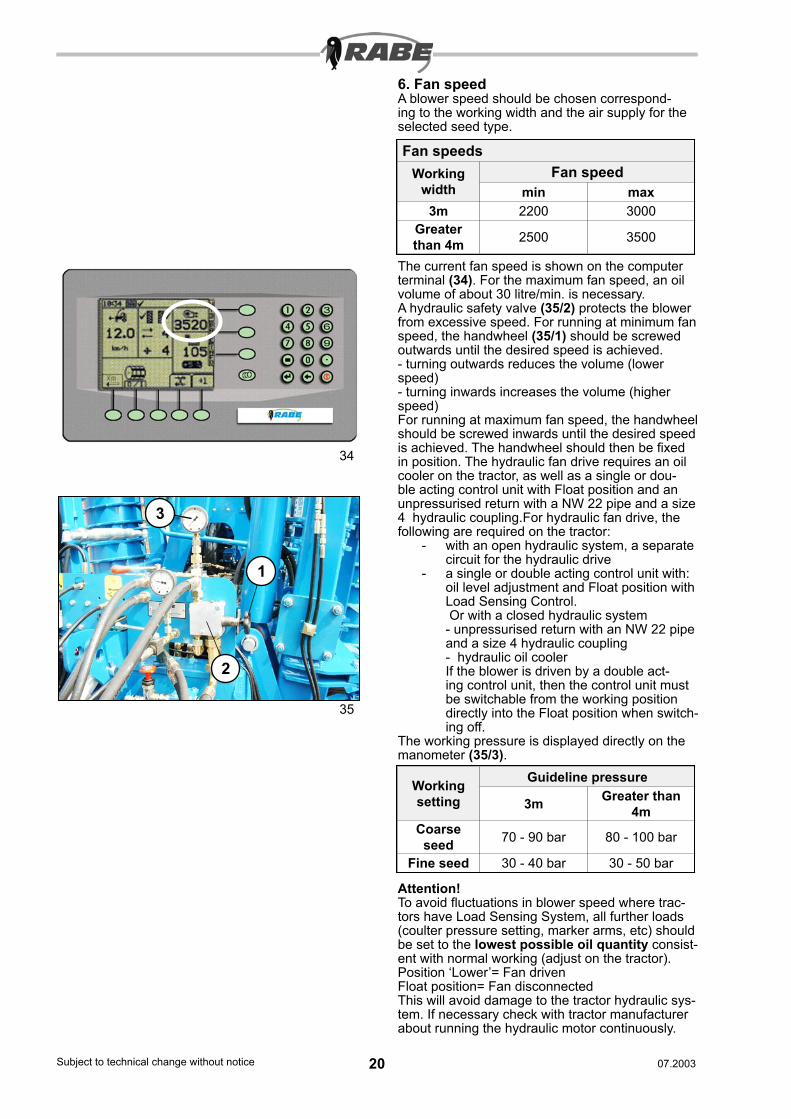
6. Fan speedA blower speed should be chosen correspond-ing to the working width and the air supply for the selected seed type.
The current fan speed is shown on the computer terminal (34). For the maximum fan speed, an oil volume of about 30 litre/min. is necessary.A hydraulic safety valve (35/2) protects the blower from excessive speed. For running at minimum fan speed, the handwheel (35/1) should be screwed outwards until the desired speed is achieved.- turning outwards reduces the volume (lower speed)- turning inwards increases the volume (higher speed)For running at maximum fan speed, the handwheel should be screwed inwards until the desired speed is achieved. The handwheel should then be fixed in position. The hydraulic fan drive requires an oil cooler on the tractor, as well as a single or dou-ble acting control unit with Float position and an unpressurised return with a NW 22 pipe and a size 4 hydraulic coupling.For hydraulic fan drive, the following are required on the tractor:
- with an open hydraulic system, a separate circuit for the hydraulic drive
- a single or double acting control unit with:oil level adjustment and Float position with Load Sensing Control. Or with a closed hydraulic system- unpressurised return with an NW 22 pipe and a size 4 hydraulic coupling- hydraulic oil coolerIf the blower is driven by a double act-ing control unit, then the control unit must be switchable from the working position directly into the Float position when switch-ing off.
The working pressure is displayed directly on the manometer (35/3).
Attention!To avoid fluctuations in blower speed where trac-tors have Load Sensing System, all further loads (coulter pressure setting, marker arms, etc) should be set to the lowest possible oil quantity consist-ent with normal working (adjust on the tractor).Position ‘Lower’= Fan drivenFloat position= Fan disconnectedThis will avoid damage to the tractor hydraulic sys-tem. If necessary check with tractor manufacturer about running the hydraulic motor continuously.
Fan speedsWorking
widthFan speed
min max3m 2200 3000
Greater than 4m 2500 3500
Working setting
Guideline pressure
3m Greater than 4m
Coarse seed 70 - 90 bar 80 - 100 bar
Fine seed 30 - 40 bar 30 - 50 bar
34
35
1
2
3
20Subject to technical change without notice 21Subject to technical change without notice07.2003 07.2003
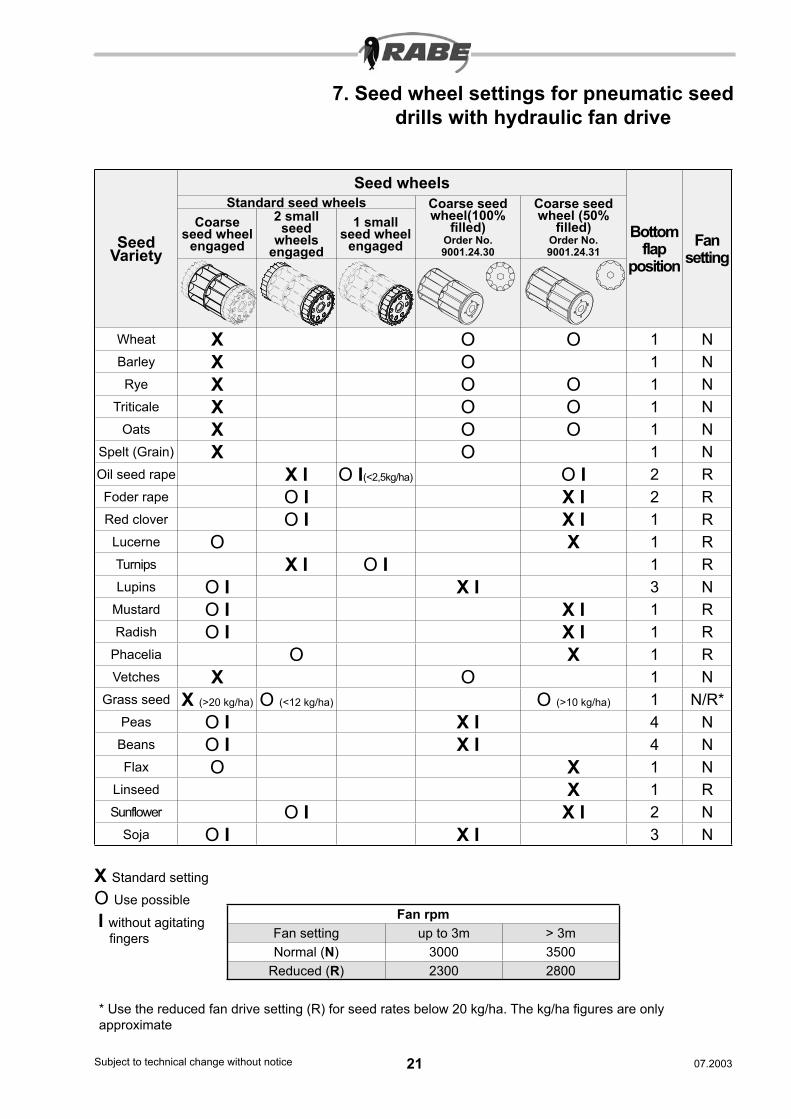
7. Seed wheel settings for pneumatic seed drills with hydraulic fan drive
X Standard settingO Use possible
* Use the reduced fan drive setting (R) for seed rates below 20 kg/ha. The kg/ha figures are only approximate
Seed Variety
Seed wheels
Bottom flap
positionFan
setting
Standard seed wheels Coarse seed wheel(100%
filled)Order No. 9001.24.30
Coarse seed wheel (50%
filled)Order No. 9001.24.31
Coarse seed wheel
engaged
2 small seed
wheels engaged
1 small seed wheel
engaged
Wheat X O O 1 NBarley X O 1 NRye X O O 1 N
Triticale X O O 1 NOats X O O 1 N
Spelt (Grain) X O 1 NOil seed rape X I O I(<2,5kg/ha) O I 2 RFoder rape O I X I 2 RRed clover O I X I 1 R
Lucerne O X 1 RTurnips X I O I 1 RLupins O I X I 3 N
Mustard O I X I 1 RRadish O I X I 1 R
Phacelia O X 1 RVetches X O 1 N
Grass seed X (>20 kg/ha) O (<12 kg/ha) O (>10 kg/ha) 1 N/R*Peas O I X I 4 N
Beans O I X I 4 NFlax O X 1 N
Linseed X 1 RSunflower O I X I 2 N
Soja O I X I 3 N
Fan rpmFan setting up to 3m > 3mNormal (N) 3000 3500
Reduced (R) 2300 2800
I without agitating fingers
22Subject to technical change without notice 23Subject to technical change without notice07.2003 07.2003
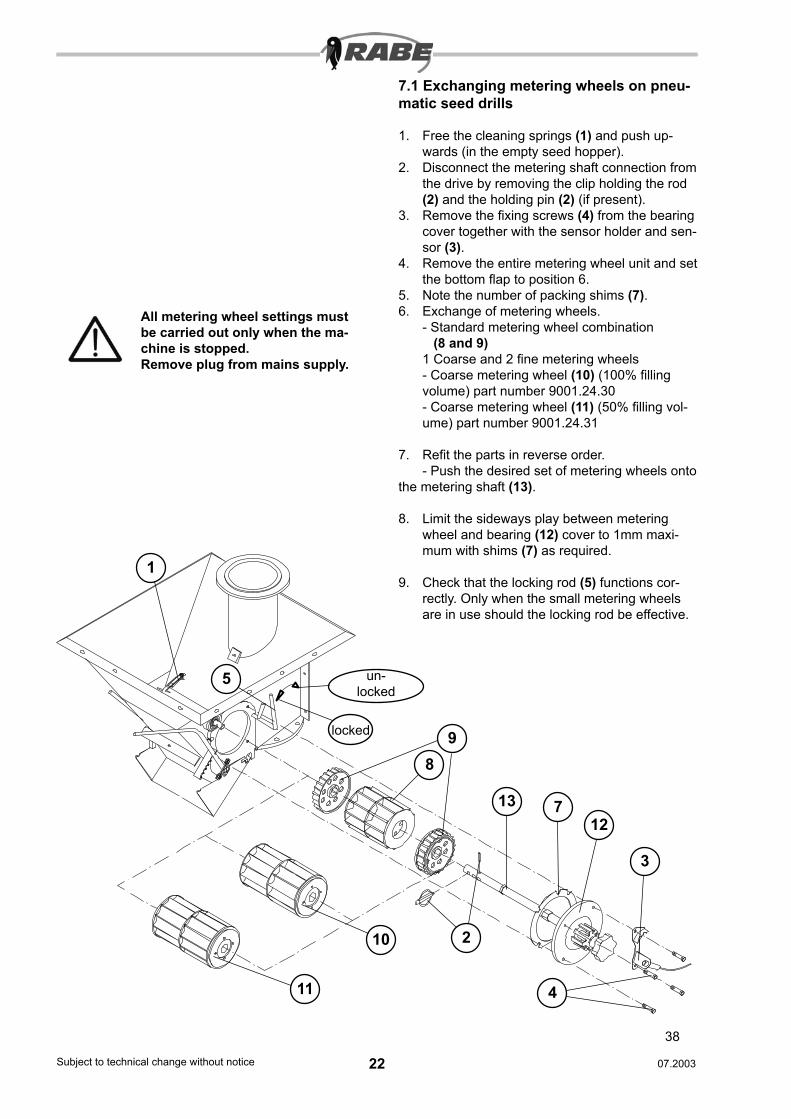
7.1 Exchanging metering wheels on pneu-matic seed drills
1. Free the cleaning springs (1) and push up-wards (in the empty seed hopper).
2. Disconnect the metering shaft connection from the drive by removing the clip holding the rod (2) and the holding pin (2) (if present).
3. Remove the fixing screws (4) from the bearing cover together with the sensor holder and sen-sor (3).
4. Remove the entire metering wheel unit and set the bottom flap to position 6.
5. Note the number of packing shims (7).6. Exchange of metering wheels.
- Standard metering wheel combination (8 and 9)1 Coarse and 2 fine metering wheels- Coarse metering wheel (10) (100% filling volume) part number 9001.24.30- Coarse metering wheel (11) (50% filling vol-ume) part number 9001.24.31
7. Refit the parts in reverse order.- Push the desired set of metering wheels onto
the metering shaft (13).
8. Limit the sideways play between metering wheel and bearing (12) cover to 1mm maxi-mum with shims (7) as required.
9. Check that the locking rod (5) functions cor-rectly. Only when the small metering wheels are in use should the locking rod be effective.
5
98
un-locked
locked
1
2
3
10
4
712
All metering wheel settings must be carried out only when the ma-chine is stopped.Remove plug from mains supply.
13
11
38
22Subject to technical change without notice 23Subject to technical change without notice07.2003 07.2003
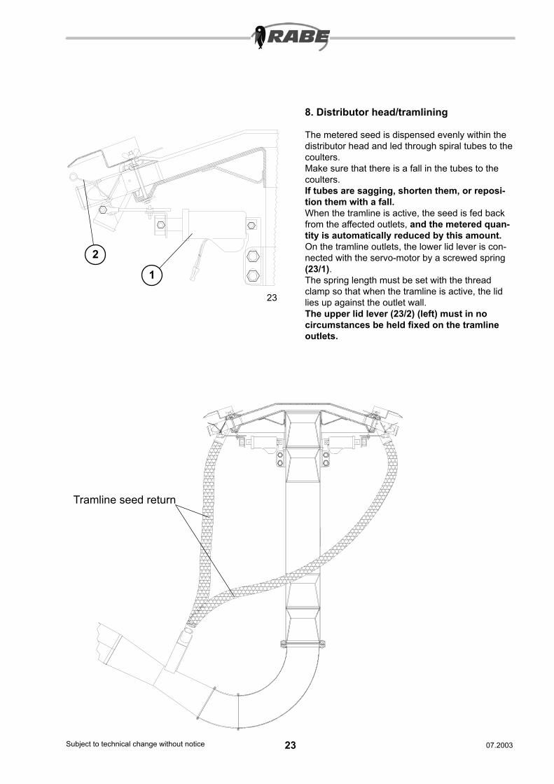
8. Distributor head/tramlining
The metered seed is dispensed evenly within the distributor head and led through spiral tubes to the coulters.Make sure that there is a fall in the tubes to the coulters.If tubes are sagging, shorten them, or reposi-tion them with a fall.When the tramline is active, the seed is fed back from the affected outlets, and the metered quan-tity is automatically reduced by this amount.On the tramline outlets, the lower lid lever is con-nected with the servo-motor by a screwed spring (23/1).The spring length must be set with the thread clamp so that when the tramline is active, the lid lies up against the outlet wall.The upper lid lever (23/2) (left) must in no circumstances be held fixed on the tramline outlets.
23
Tramline seed return
2
1

24Subject to technical change without notice 25Subject to technical change without notice07.2003 07.2003
9.1 Tips for use
- Make the drill combination ready for use: track eradicators, tilling tools, undercar-riage, ground wheel, markers, tramline system, pre-emergance marking, fan speed/hydraulic motor.
- Check settings (such as calibration test): metering wheel setting (lock coarse me-tering wheel for fine seeds), bottom flap, agitator shaft (remove agitator fingers for rapeseed), calibration flap, seed quantity setting.
- Switch on the electronics, check tramline rhythm, set cycle position for the first run.
- When starting (even before engaging) run at 1/2 motor speed as a minimum, then maintain constant speed.
- When engaging and starting sowing, the seed requires a certain time to reach the sowing coulters from the metering unit (about 1 sec. for every 2 metres). Remem-ber this after a pause. Therefore raise the unit and set back (see pre-metering).
- Before sowing, check all coulters for blockages, and re-examine regularly thereafter.
- Check sowing depth.- Adjust the travelling speed to the quality of
work, so that the seedbed stays even.- Always keep the control unit for the marker
arms in floating position while sowing (see also marker arms).
- When filling the seed hopper, ensure that no foreign bodies (pieces of paper, attach-ments to sacks) get into the hopper. Keep the hopper lid closed while working. Keep an eye on the seed level in the hopper (Low level warning).
- Because of the hygroscopic nature of seed and dressing, empty the seed hopper and metering unit when laying up the unit for a long period. Beware that dressing is an irritant and is poisonous.
Removal of residues: lower the drill machine, place a vessel under the outlet funnel, open the empty-ing flap. After emptying, turn all metering wheels a little (with star grip 33/2), and with the control, run the blower briefly to remove all residues (to avoid attracting rodents). Leave the emptying flap open.
9. Checking sowing precision on seed drills with electrically driven metering wheels
Rule 1The electrical calibration test and the
manual calibration test on the tailwheel should always give the same calibration
values (only negligible differences are ac-ceptable).
Rule 2The setting of the electronic area counter must be based on the working width of
the machine.
Rule 3Undertake the calibration procedure only
when the tramline is not switched on.
Rule 4Undertake the calibration procedure only when ”increased sowing rate” is not ac-
tive.
Rule 5Select metering wheel and bottom flap
settings which have been recommended.
Rule 6Use tested scales (household scales). Do not use spring balances or sack scales.
Only by following these rules will the most accurate sowing rates be
achieved.
24Subject to technical change without notice 25Subject to technical change without notice07.2003 07.2003
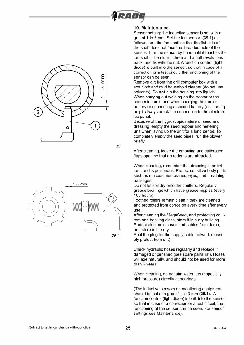
10. MaintenanceSensor setting: the inductive sensor is set with a gap of 1 to 3 mm. Set the fan sensor (39/1) as follows: turn the fan shaft so that the flat side of the shaft does not face the threaded hole of the sensor. Turn the sensor by hand until it touches the fan shaft, Then turn it three and a half revolutions back, and fix with the nut. A function control (light diode) is built into the sensor, so that in case of a correction or a test circuit, the functioning of the sensor can be seen.Remove dirt from the drill computer box with a soft cloth and mild household cleaner (do not use solvents). Do not dip the housing into liquids.When carrying out welding on the tractor or the connected unit, and when charging the tractor battery or connecting a second battery (as starting help), always break the connection to the electron-ics panel.Because of the hygroscopic nature of seed and dressing, empty the seed hopper and metering unit when laying up the unit for a long period. To completely empty the seed pipes, run the blower briefly.
After cleaning, leave the emptying and calibration flaps open so that no rodents are attracted.
When cleaning, remember that dressing is an irri-tant, and is poisonous. Protect sensitive body parts such as mucous membranes, eyes, and breathing passages.Do not let soil dry onto the coulters. Regularly grease bearings which have grease nipples (every 100 hours).Toothed rollers remain clean if they are cleaned and protected from corrosion every time after every use.After cleaning the MegaSeed, and protecting coul-ters and tracking discs, store it in a dry building.Protect electronic cases and cables from damp, and store in the dry.Seal the plug for the supply cable network (possi-bly protect from dirt).
Check hydraulic hoses regularly and replace if damaged or perished (see spare parts list). Hoses will age naturally, and should not be used for more than 6 years.
When cleaning, do not aim water jets (especially high pressure) directly at bearings.
(The inductive sensors on monitoring equipment should be set at a gap of 1 to 3 mm (26.1). A function control (light diode) is built into the sensor, so that in case of a correction or a test circuit, the functioning of the sensor can be seen. For sensor settings see Maintenance).
1 - 3mm
26.1
1 -
3 m
m
39
1
2
26Subject to technical change without notice 27Subject to technical change without notice07.2003 07.2003
26.2
26.3
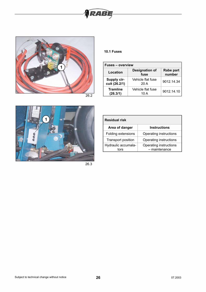
10.1 Fuses
Residual risk
Area of danger InstructionsFolding extensions Operating instructions
Transport position Operating instructionsHydraulic accumala-
torsOperating instructions
– maintenance
Fuses – overview
Location Designation of fuse
Rabe part number
Supply cir-cuit (26.2/1)
Vehicle flat fuse 20 A 9012.14.34
Tramline (26.3/1)
Vehicle flat fuse 10 A 9012.14.10
1
1
26Subject to technical change without notice 27Subject to technical change without notice07.2003 07.2003
10.2 Faults and their resolution
ResolutionFaults10.2.1 Electronic faults
1. The electronics do not switch on.
2. The motor for tramline switching is inactive.
3. The metering shaft monitoring does not work.
4. Tramline does not switch forward.
5. Metering motor permanently runs at full speed when the electronics are switched on.
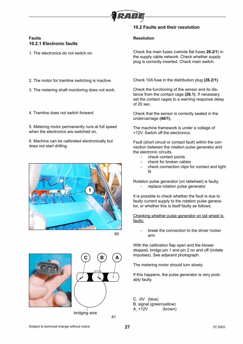
6. Machine can be calibrated electronically but does not start drilling.
40
41
Check the main fuses (vehicle flat fuses 26.2/1) in the supply cable network. Check whether supply plug is correctly inserted. Check main switch.
Check 10A fuse in the distribution plug (26.2/1).
Check the functioning of the sensor and its dis-tance from the contact cage (26.1). If necessary set the contact cages to a warning response delay of 20 sec.
Check that the sensor is correctly seated in the undercarriage (40/1).
The machine framework is under a voltage of +12V. Switch off the electronics.
Fault (short circuit or contact fault) within the con-nection between the rotation pulse generator and the electronic circuits.
- check contact points- check for broken cables- check connection clips for contact and tight
fit
Rotation pulse generator (on tailwheel) is faulty.- replace rotation pulse generator
It is possible to check whether the fault is due to faulty current supply to the rotation pulse genera-tor, or whether this is itself faulty as follows:
Checking whether pulse generator on tail wheel is faulty:
- break the connection to the driver rocker arm
With the calibration flap open and the blower stopped, bridge pin 1 and pin 2 on and off (imitate impulses). See adjacent photograph.
The metering motor should turn slowly.
If this happens, the pulse generator is very prob-ably faulty.
C. -0V (blue)B. signal (green/yellow)A. +12V (brown)
bridging wire
C B A
1
28Subject to technical change without notice 29Subject to technical change without notice07.2003 07.2003
Faults
Faults and their resolution
Resolution
10.2.2 Mechanical faults1. Sowing stops for a row
a) individual tubes blocked due to blockage in coulter.
b) individual tubes blocked due to poor tube posi-tioning (sagging)
c) insufficient air supply
d) Blockage in distributor head due to foreign bod-ies
e) Pattern of tramline switching motor is set falsely
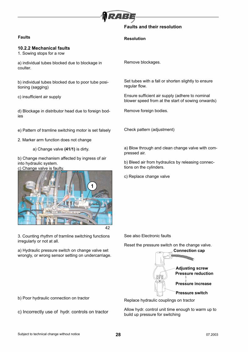
2. Marker arm function does not change
a) Change valve (41/1) is dirty.
b) Change mechanism affected by ingress of air into hydraulic system.c) Change valve is faulty.
3. Counting rhythm of tramline switching functions irregularly or not at all.
a) Hydraulic pressure switch on change valve set wrongly, or wrong sensor setting on undercarriage.
b) Poor hydraulic connection on tractor
c) Incorrectly use of hydr. controls on tractor
Remove blockages.
Set tubes with a fall or shorten slightly to ensure regular flow.
Ensure sufficient air supply (adhere to nominal blower speed from at the start of sowing onwards)
Remove foreign bodies.
Check pattern (adjustment)
a) Blow through and clean change valve with com-pressed air.
b) Bleed air from hydraulics by releasing connec-tions on the cylinders.
c) Replace change valve
See also Electronic faults
Reset the pressure switch on the change valve.
Replace hydraulic couplings on tractor
Allow hydr. control unit time enough to warm up to build up pressure for switching
42
Connection cap
Adjusting screwPressure reduction
Pressure increase
Pressure switch
1
28Subject to technical change without notice 29Subject to technical change without notice07.2003 07.2003
Faults Resolution
5. Shear bolts on marker arms shear frequently becausea) Grip on marker discs is too strong.
b) The marker arms are used when in the blocked position
6. Tramline switching functions irregularly or not at alla) Tramline motor does not pull.
b) Lever mechanism on distributor outlet is faulty.
7. Desired output rate is not achieved.
a) Through faulty calibration.
b) Because of stuck or blocked sowing wheels
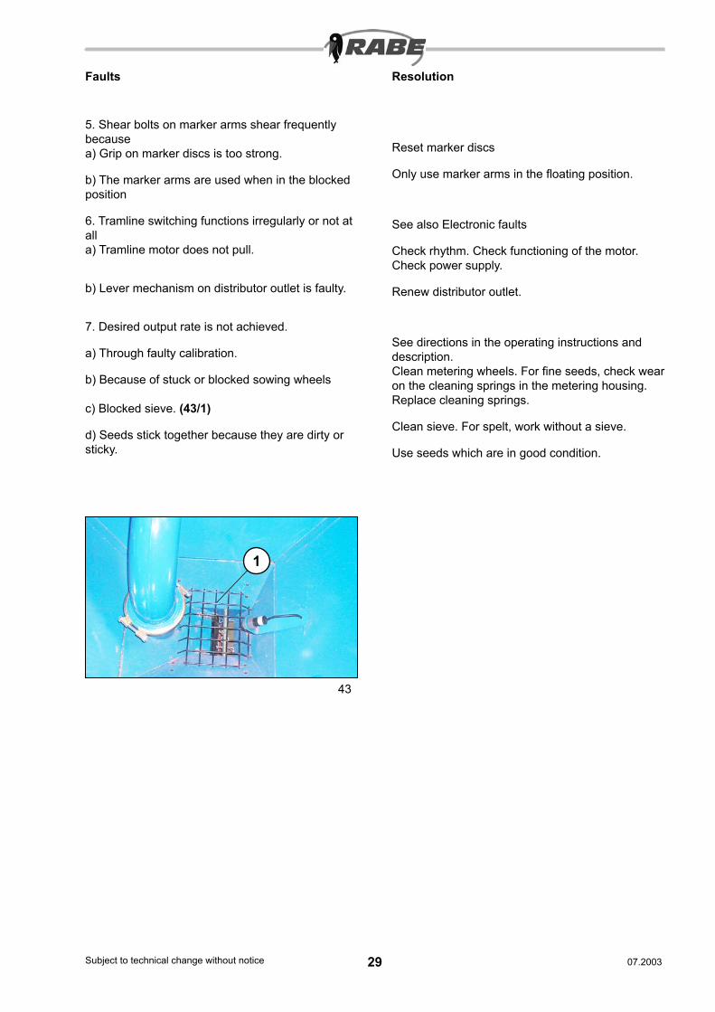
c) Blocked sieve. (43/1)
d) Seeds stick together because they are dirty or sticky.
Reset marker discs
Only use marker arms in the floating position.
See also Electronic faults
Check rhythm. Check functioning of the motor. Check power supply.
Renew distributor outlet.
See directions in the operating instructions and description.Clean metering wheels. For fine seeds, check wear on the cleaning springs in the metering housing. Replace cleaning springs.
Clean sieve. For spelt, work without a sieve.
Use seeds which are in good condition.
43
1
30Subject to technical change without notice 31Subject to technical change without notice07.2003 07.2003
11. Transport precautions
Put the unit into the transport position. Check that it is suitable to be transported.
Travelling on the unit and staying within its area of danger are forbidden.
Towed units weighing more than 3 t require a traf-fic permit. If the axle load is greater than 3 t, they must have a braking system.
Depending on the traffic permit, maximum speed is either 25 km/h or 40 km/h.
Adapt transport speed to the conditions of the high-way.
Take care on slopes and in curves. Take the centre of gravity into account.
Observe the requirements of the road traffic regu-lations. These make the user responsible for the tractor and trailer being connected together in a way that is safe to traffic when travelling on public highways.
Working equipment must not impede the safe movement of the combination. The connected unit must not cause the permitted tractor axle load, overall weight, and the load bearing capacity of the tyres (depending on speed and air pressure) to be exceeded. To ensure steering safety, the front axle loading must be at least 20% of the unladen vehicle weight.
The maximum permitted width for transport is 3m. The overall length of the combination may be 18m maximum.
If the maximum permitted dimensions are exceed-ed, a special permit must be obtained. To avoid danger to traffic, no part must project from the outline of the vehicle more than is absolutely nec-essary. If it cannot be avoided that parts project, they should be covered and made conspicuous. Safety measures must also be taken to make the outermost contours of the unit conspicuous, and to ensure safety at the rear. For example, fit red/white striped warning shields (423 x 423mm, stripes 100mm width at an angle of 45° running outwards and downwards).
Towed or saddle units should be fitted with red rear reflectors, and yellow reflectors at the side when being moved, as well as having their lights illumi-nated, even during the day (as well as clearance lights when the unit projects more than 400mm beyond the tractor lights).The safety coverings required for transport in traffic on public highways are available from RABE.The safety information (TÜV) required for a traffic permit can also be obtained from RABE.
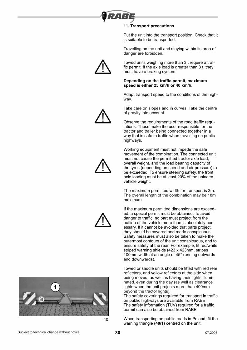
When transporting on public roads in Poland, fit the warning triangle (40/1) centred on the unit.
1
40
30Subject to technical change without notice 31Subject to technical change without notice07.2003 07.2003
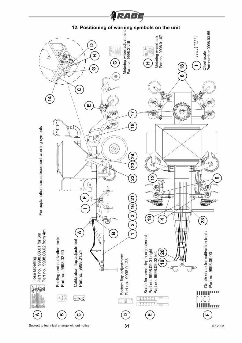
For e
xpla
natio
n se
e su
bseq
uent
war
ning
sym
bols
12. Positioning of warning symbols on the unit
III
III
Pos.
I F
eind
osie
rrad
1
S
mal
l met
erin
g w
heel
1
R
oue
à pe
tite
cann
elur
es 1
Pos.
II F
eind
osie
rrad
1+2
Sm
all m
eter
ing
whe
el 1
+2
R
oue
à pe
tite
cann
elur
es 1
et 2
Pos.
III G
robd
osie
rrad
Lar
ge m
eter
ing
whe
el
R
oue
à gr
osse
s ca
nnel
ures
9998
.01.
18
gesperrt
locked
bloqué
frei
unlocked
libre
Met
erin
g w
heel
adj
ustm
ent
Part
no.
9998
.01.
18
Met
erin
g w
heel
lock
Pa
rt no
. 99
98.0
1.67
9998.09.03
23
1621
124
2322
14
1817
186
23
1920
4
6
1812
Auf
ladu
ng S
char
schi
enen
Geb
läse
Dru
ck/R
ückl
auf
Fahr
wer
k
Eink
lapp
en+V
orw
erkz
euge
Spu
ranr
eiße
r
9998
.08.
02
Fold
ing
+ fro
nt cu
ltivat
ion
Rep
liage
+ O
utils
Fan
pres
sure
/ re
turn
Turb
ine
pres
sion
/ ret
our
Load
on
coul
ter b
arPo
int d
éncr
age
de la
ram
pe
Tran
spor
t whe
els
char
iot d
e tra
nspo
rt
Trac
k m
arke
rsTr
açeu
rs
Abdrehen
Calibration
Contrôle
Säen
Sowing
Semis
9998.01.24
9998.02.90
9998.01.23
AH
ose
labe
lling
Part
no.
9998
.08.
01 fo
r 3m
Part
no.
9998
.08.
02 fr
om 4
m
B
Fold
ing
and
culti
vatio
n to
ols
Part
no.
9998
.02.
90
B
C
D
C D
Cal
ibra
tion
flap
adju
stm
ent
Part
no.
9998
.01.
24A
Botto
m fl
ap a
djus
tmen
tPa
rt no
. 99
98.0
1.23
9998.09.01
9998.09.02
ESc
ale
for s
eed
dept
h ad
just
men
tPa
rt no
. 999
8.09
.01
right
Part
no. 9
998.
09.0
2 le
ft
E
F
F
Dep
th s
cale
for c
ultiv
atio
n to
ols
Part
no. 9
998.
09.0
3
G H
HG
9998.03.55
54321012345
IO
ffset
sca
lePa
rt nu
mbe
r 999
8.03
.55
I