Embed Size (px)
Citation preview
OPERATING INSTRUCTIONS FOR
TYPE 605-A STANDARD-SIGNAL
GENERATOR FORM 429 C

PATENT NOTICE
This instrument is licensed under patents of the American Telephone and Telegraph Company, solely for utilization in research, investigation, measurement, testing, .instruction, and devel9pment work in pure and applied science. ·
SPARE TUBE A SPARE 955-TY?E V ,t.CUUM TUBft IS SHIPPED INSiDE THE CABINEt Of THIS INSTRUMENT,
OPERATING INSTRUCTIONS FOR
TYPE 605-A STANDARD-SIGNAL
GENERATOR
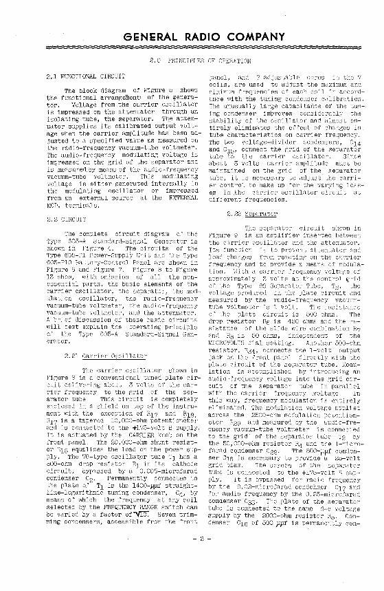
1.0 DESCRIPTION
l.l PURPOSE
The Type 605-A Standard-Signal Generator is a device for producing radiofrequency oscillations over a wide frequency band and is so arranged and shielded that a continuously-variable calibrated output voltage is obtainable across its output terminals. It is designed and intended primarily for testing radio receivers.
1,2 FREQUENCY RANGE
The frequency range is 9.5 kc to 30 Me. This range is covered by seven steps which can be chosen by a band chan~e switch on the front of the panel. Within each range the frequency is varied by means of a straight-line-logarithmic condenser. Percentage frequency change, therefore, is proportional to tuning condenser dial rotation. The dial is directreading in frequency over the entire range and can be set with an accuracy better than l per cent without calibration,
An additional oscillator coil covering a ran:;e from 30 to 50 Me is also provided. These frequencies are outside the design range of th.e instrument and no gua ran tee of accuracy is made for either frequency or output voltage.
A frequency calibration for this coil is given on page 11.
l. 3 OUTPUT
The output is qontinuously variable from 0.5 microvolt to 0.1 volt and is determined by the settings of two attenuator dials and the reading of a vacuum-tube voltmeter. In addition to this variable output a constant output of 1 volt can be obtained directly across the vacuum-tube voltmeter. The output may be obtained
either unmodulated or modulated Modulation is adjustable between 0 and 50 per cent. An internal source for modulation at 400 cycles per second is provided. Provision is also made for the use of external modulation.
l. 4 POVJER SUPPLY
1.41 A-C Operation
The Type 6::5-A Standard-Signal Generator is designed to be used in connection with the Type 605-Pl Power Supply Unit operated from the mains. This unit, built on a separate panel, is mounted in the signal generator cabinet. All necessary connections are made 1nside. The power transformer is of the flux-regulated type and will deliver constant plate and filament voltages independent of ordinary line voltage fluctuations. Since the flux density of the transformer depends on the a-c line frequency, power supplies are built for 60-, 50-, and 42-cycle lines.
1.42 Battery Operation
For battery operation the power supp~~ can be replaced by the Type 605-PlO Control Panel. which has the necessary meters and rheostats to maintain the correct operating voltages.
1.43 Operating Vc~cages
For proper operation and to obtain the rated accuracy it is important that plate and filament voltages bo kept constant at the specified values. Plate supply voltage is 200 volts. Of these 25 volts are used as bias and 175 as plate voltage. Filament voltage is 5.8 volts. No connection can exist between plate and filament supply outside the instrument.
- 1 -
GENERAL RADIO COMPANY
2.0 PRINCIPLES OF O?EFATION
2.1 FUNCTIONAL CIRCUIT
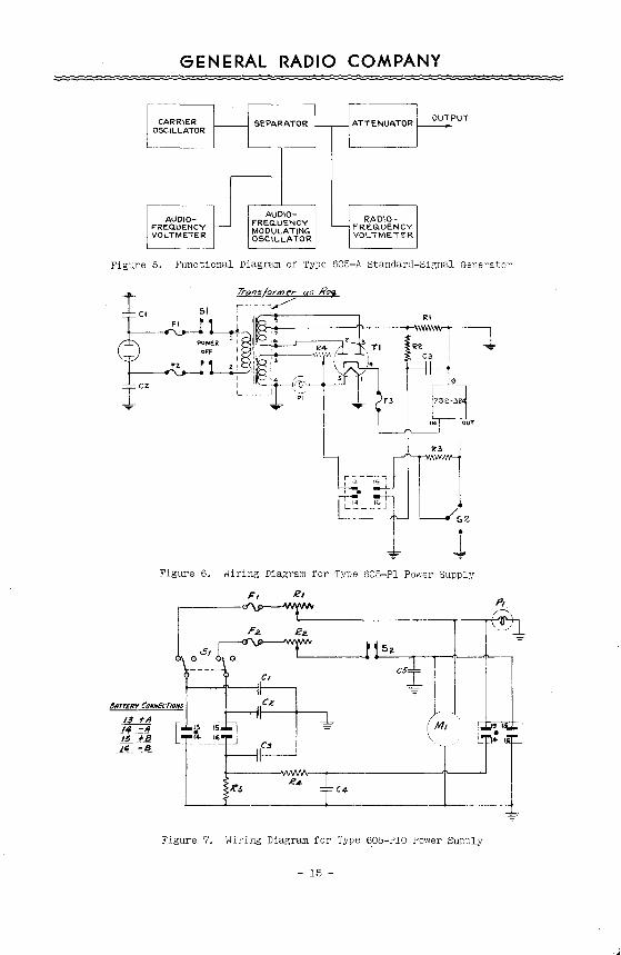
The block diagram of Figure 5 shows the functional arrangemenV of the generator. Voltage from the carrier oscillator is impressed on the attenuator through an isolating tube, the separator. The attenuator supplies its calibrated output voltage when the carrier amplitude has been adjusted to a specified value as measured on the radio-frequency vacuum-tube voltmeter. The audio-frequency modulating voltage is impressed on the grid of the separator and is measured by means of the audio-frequency vacuum-tube voltmeter. This modulating voltage is either generated internally in the modulating oscillator or impressed from an external source at the EXTERNAL MOD. terminals.
2. 2 CIRCUIT
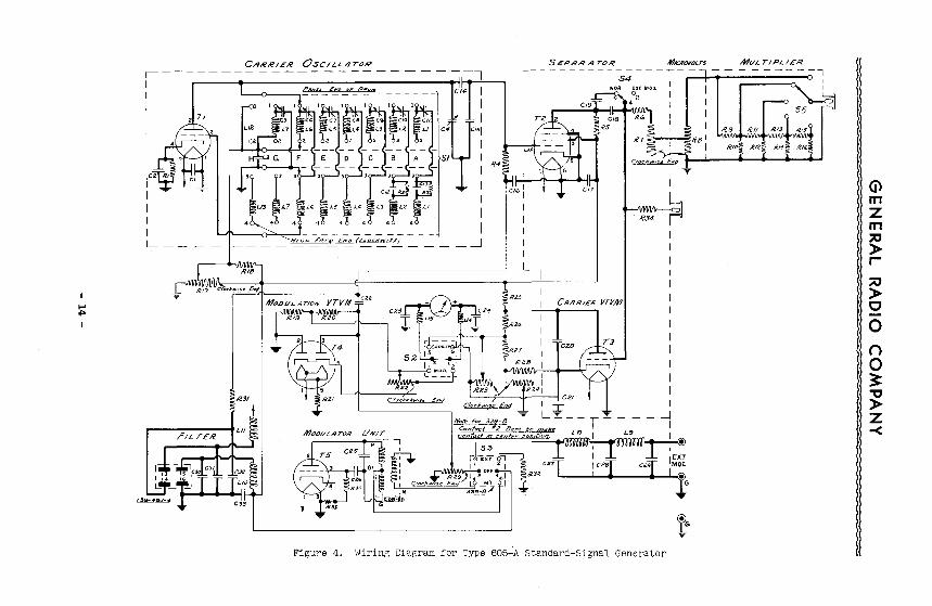
The complete circuit diagram of the Type 605-A Standard-Signal Generator is shown in Figure 4. The circuits of the Type 605-Pl Power-Supply Unit and the Type 605-PlO Battery-Control Panel are shown in Figure 6 and Figure 7. Figure 8 to Figure 13 show, with omission of all the nonessential parts, the basic elements of the carrier oscillator, the separator, the modulation oscillator, the radio-frequency vacuum-tube voltmeter, the audio-frequency vacuum-tube voltmeter, and the attenuator. A brief discussion of these basic circuits will best explain the operating principle of the Type 605-A Standard-Signal Generator.
2.21 Carrier Oscillator
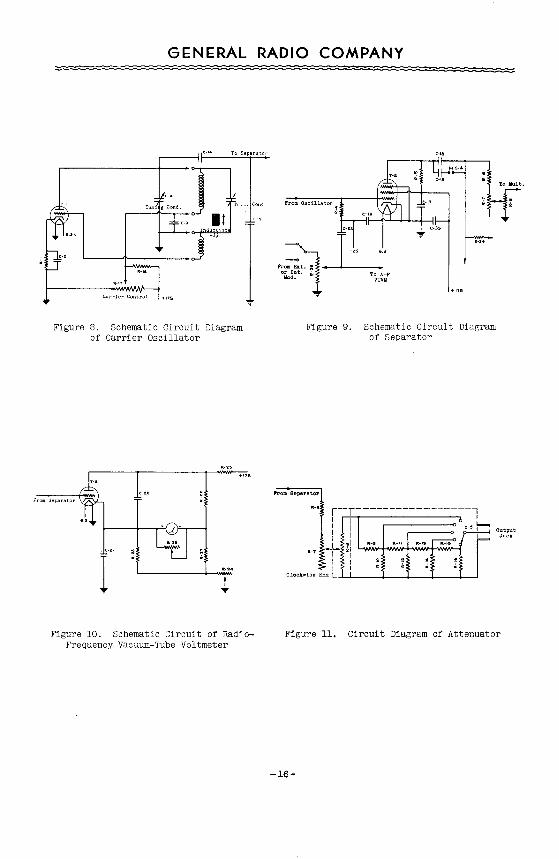
The carrier oscillator shown in Figure 8 is a conventional tuned plate circuit delivering about 3 volts of the carrier frequency to the grid of the separator tube This circuit is completely enclosed in a shield on top of the instrument with the exception of R17 and ~18. R17 is a tapered 10,000-ohm potentiometer and is connected to the +175-volt B supply. It is actuated by the CARRIER knob on the front panel. The 20,000-ohm shunt resistor '118 equalizes the load on the power supply. The 76-type oscillator tube T1 has a 600-ohm drop resistor R1 in its cathode circuit, bypassed by a 0.005-microfarad condenser c2. Permanently connected to ;he plate of T1 is the 1400-ppf straightline-logarithmic tuning condenser, C4, by means of which the frequency at any coil selected by the FREQUENCY RANGE switch can be varied by a factor of -vr:D. Seven trimming condensers, accessible from the front
panel, and 7 adjustable cores in the 7 coils, are used to adjust the maximum and minimum frequencies of each coil in accordance with the tuning condenser calibration. The unusually large capacitance of the tuning condenser improves considerably the stability of the oscillator and almost entirely eliminates the enect of changes in tube characteristics on carrier frequency. The two voltage-divider condensers, C14 and c15, connect the grid of the separator tube to the carrier oscillator. Since about 3 volts carrier amplitude must be maintained on the grid Of the separator tube, it is necessary to adjust the carrier control to make up for the varying losse.s in .the carrier oscillator circuit at different frequencies.
2.22 Separator
The separator circuit shown in Figure 9 is an amplifier inserted between the carrier oscillator and the attenuator. Its function is to prevent attenuator and load changes from reacting on the ca"rier frequency and to provide a means of modulation. Lith a carrier frequency voltage of approximately 3 volts at the control grid of the Type 89 Separator Tube, the voltage produced in the plate and measured by the radio-frequency vacuumtube voltmeter is 1 volt. The resista~ce
of the plate circuit is 500 ohms. The drop resistor RB is 450 ohms and the resistance of the slide wire combination R7 and R8 is 50 ohms, independent of the MICROVOLTS dial setting. Another 500-ohm resistor, R34, connects the 1-volt output jack on the front panel directly with the plate circuit of the separator tube. l\Iodulation is accomplished by introducing an audio-frequency voltage into the grid circuit of the separator tube in parallel with the carrier frequency voltage. In this way, frequency modulation is entirely eliminated. The modulation voltage applied across the 2500-ohm modulation potentiometer R29 and measured by the audio-frequency vacuum-tube voltmeter is connected to the grid of the separator tube T2 by the 50,000-ohm resistor R4 and the 1-microfarad cqndenser 022· The 500-ppf condenser C15 is necessary to provide a 25-volt grid bias. The screen of the separator tube is connected to the +175-volt B supply. It is bypassed for radio frequency by the 0.02-microfarad condenser 017 and for audio frequency by the 0.25-microfarad condenser 033· The plate of the separator tube is connected to the same d-e voltage supply by the 2000-ohm resistor R5. Condenser C1s of 500 pyf is permanently con-
- 2 -
GENERAL RADIO COMPANY
nected between the plate of the separator tube T2 and the attenuator. Condenser C19 of 0.005 pf is connected only in the NORMAL position of switch s4 . This normal position is intended for unmodulated carrier output and can be used for modulation frequencies up to about l kilocycle. High~r modulation frequencies can be applied but a relatively large amount of audio-frequency voltage would appear at the output terminals of the attenuator. Py setting switch S4 to the EXTERNAL MOD. position, the impedance of the coupling condenser is increased 10 to l and the amount of audio frequency present in the output is reduced in about the same ratio.
Because of this increased coupling impedance, carrier frequencies below 300 kilocycles cannot be produced in the EXTERNAL MOD. position of switch s4.
2.23 Radio-Frequency Vacuum-Tube Voltmeter The radio-frequency voltage pro
duced across Re, R7 and Rg in the plate circuit of the ~eparator tube is measured by the vacuum-tube voltmeter shown in Figure 10. The #955 Acorn Type Tube, T3, is used because of its short leads. At zero grid voltage, the current through the 200-pa meter is balanced out by that through the 10,000-ohm resistor R2B· With grid voltage applied, the plate current will change by an amount proportional to the average voltage applied and the meter will read. Two adjustments are provided. R24• a 1000-ohm potentiometer located on the front panel, produces the bias required for proper balance and must be adjusted from time to time to compensate for changes in the characteristic of the #955 Rectifier Tube, T3 . The second adjustment is the 2500-ohm rheostat R23 shunting the meter, which is set to give exactly halfscale deflection of the meter when l volt appears across the attenuator input. This point on the meter is marked SET CARRIER. The rheostat is located inside the instrument and does not have to be adjusted unless the voltmeter tube is replaced. R25 (100,000 ohms), R26 (20,000 ohms) and R27 (500 ohms) form a voltage divider which delivers about 30 volts to the plate of the tube, T3 , when 175 volts are applied. The usual drift in vacuum-tube voltmeter circuits due to line voltage fluctuetions is eliminated by the regulated power supply, and the indications of the voltmeter are correct for all line voltages within the rating given on the front panel of the power supply.
2.24 Attenuator
The setting of the attenuator shown in Figure ll controls the amplitude
of the carrier vol ~age applied to the output jack. The system is resistive throughout and the attenuation is independent of frequency. The attenuator system is strictly a ratio operating device but the two panel controls are calibrated directly in terms of microvolts. This calibration is correct only, of course, when the input voltage to the attenuator between R6 and ground has been set to the proper value.
There are three principal elements in the attenuator. The 450-ohm drop resistor Re• the slide wire combination R7 and Rg operated by the MICROVOLTS dial, and the completely shielded MULTIPLIERwith the resistors R9 to R16 . Re reduces the voltage applied to the slide wire to 0.1 volt since the tapered 50-ohm resistor R7 is designed to keep at exactly 50 ohms the resistance between ~ and ground. The MICROVOLTS dial drives by a common shaft the blades on R7 and Rg and indicates the attenuation introduced. The narrow AyrtonPerry-wound non-inductive resistance striP R8 with a total of 95 ohms connects through a short tube to the multiplier Switch s5 and the 8 resistors R9 to R15 are built in and shielded by a brass casting, the multiplier. This four-section ladder network is designed to attenuate in 4 steps with a ratio of 10 to l between steps. The lowest calibrated output voltage obtainable on the standard-signal generator is 0.5 microvolt. As the microvolt dial is turned further in a clockwise direction the output voltage will be still further decreased and will come to almost zero. The output impedance of the signal generator is independent of the MICROVOLTS dial setting and constant at 10 ohms with the exception of the last step from 10,000 to 100,000 microvolts (position of the MULTIPLIER=lO,OOO), where the impedance is 50 ohms.
2.25 Modulation Oscillator
The modulation oscillator, a conventional Hartley-type circuit, is shown in Figure 12. The iron-core inductor is tuned to a frequency of 400 cycles by a 0.25-microfarad condenser c25 . The grid leak resistor R30 is 2 megohms. With a +175-volt plate voltage, the audio-frequency voltage produced across the 2500-ohm MODULATION potentiometer R29 is about 8 volts. To eliminate a shift in carrier frequency between unmodulated and internally modulated signals, switch s3 is provided. The plate voltage is removed from the 76-type tube, T5, when the modulation oscillator is not in use and a dummy load of 50,000 ohms (R32) is substituted for that of the tube.
- 3 -
GENERAL RADIO COMPANY :::= =::: := == : =:= ==:;;::=:= = = : =: := ; ; =:=:=:= = = =-====:=:=:=:=:=:=:=: : =:= : :
2.26 Audio-Frequency Vacuum-Tube Voltmeter
The percentage modulation of the carrier frequency is determined by the modulation voltage applied to the control grid of the separator tube T2. The voltages required for 20, 30, 40 and 50 per cent modulation are 2.5, 3.75, 5, and 6.25 volts approximately. This modulation voltage is taken off the 2500-ohm MODULATION potentiometer R29 and measured with the audiofrequency vacuum-tube voltmeter shown in Figure 13. According to the position of switch s3 , the MODULATION potentiometer is connected either to the internal 400-cycle modulator or to the EXTERNAL MOD. binding posts. To eliminate distortion in the measuring circuit a full-wave 84-type rectifier tube T4 is used to measure the modulation voltage. The two 15,000-ohm resistors R19 and R20 provide an artificial center point. The 10,000-ohm potentiometer R22 determines the sensitivity of the voltmeter. The meter is the same 200-microampere meter used to measure carrier amplitude and is shifted from one circuit to the other by the METER READS switch s2. The lower scale of the meter is marked 20, 30, 40 and 50 per cent modulation.
2.27 Power Supply
The Type 605-Pl Power Supply shown in Figure 6 is a conventional fullwave rectifier circuit employing a fluxregulated transformer to compensate for line voltage fluctuations. For different a-c line frequencies and voltages, different regulator transformers must be used.
Frequency and voltage range are clearly marked on the front panel of each instrument. The regulator transformers are designed to deliver constant output for line voltage fluctuations of abouc±l2 per cent from rated value when working into a constant load. The resistors R18 (across the carrier potentiometer R17) and R32 (the dummy resistance in the modulating circuit) are used to keep the load constant. Likewise, R3 in the power supply itself replaces the plate load of the entire signal generator in the "PLATE-OFF" position· of switch s 2 . \Hthout this resistance the plate voltage of the power supply might rise to a dangerously high value and arc a~ross filter condensers when the load is removed. This fact should be remembered when testing the power supply without the signal generator. With the proper load, the plate current will be 37 milliamperes and the voltage produced across R1 will be 25 volts which is needed as bias for the separator tube. The hum voltage is less than 0.1%.
2.28 Control Panel
The Type 605-PlO Control Panel shown in Figure 7 is used when the signal generator is operated from batteries. Current and voltage requirements are 200 volts, 37 rna and 6 volts, 1.7 amperes. The meter M1 and the rheostats R1 and R2 should be used to maintain these voltages accurately. Sli~ht variations in the voltages will not impair the operativn of the signal generator but will affect the accuracy of the absolute level of output as read or the carrier vacuum-tube voltmeter.
3.0 OPERATING INSTRUCTIONS
3.1 INSTALLATION the power supply or control panel are made inside.
The Type 605-A Standard-Signal Generator is shipped with the Type 605-Pl Power Supply (or with the Type 605-PlO Control Panel) mounted together in one cabinet and ready for use. All-tubes required are shipped in place and all connections between the standard-signal generator and
3.11 vacuum Tubes, Pilot Lights and Fuses
All tubes required are furnished with each instrument and shipped solidly held in place inside of the Instrument.
Type 605-A Standard-Signal Generator
Vacuum Tube T e Function
76 R-F Oscillator 76 A-F Modulator 89 Separator 84 A-F Voltmeter
955 R-F Voltmeter
Location
Inside shielded unit at top Left front corner of amplifier shelf In shield at middle of amplifier shelf Left rear corner of amplifier shelf Ring socket accessible from bottom of amplifier shelf
- 4 -
GENERAL RADIO COMPANY
Type 605-Pl Power Supply
Function
Rectifier Line Fuse Line Fuse Plate Fuse Pilot Light
Type or Rating
84 2.5A·Bussman #7AG 8.5A Bussman #7AG O.lA Bussman #7AG
5-6 Volt
Type 6U5-Pl0 Control Panel
Function
Plate Fuse Filament Fuse Pilot Light
3.12 A-C Power Supply
When using Type 605-Pl Power Supply, be sure the line voltage and frequency are those engraved on its front panel. Connect to the line with the 6-foot cord supplied with the instrument.
The Type 605-Pl Power Supply for 5C cycles per second line frequency can be changed easily to work either from 100-130 volts line voltage or 200-260 volts. There are 3 terminal strips on the regulatAd transformer. The middle strip has 4 terminals: 9, 10, ll and 12, For o~eration from 100-130 volts, terminal 9 is connected to terminal ll and terminal 10 is connected to terminal 12. For operation from 200-260 volts, terminal 10 is connected to terminal 11. In either case terminal 9 is connected to terminal 1 and terminal 12 to terminal 2, terminals 1 and 2 being on the terminal strip on top. When a change in terminal connections is made on the transformer the engraved name plate on the front panel should be changed as well. Type 605-Pl Power Supplies for 50-cycle line frequency are furnished with 2 of these name plates, one fastened under the other. Care should be taken that the name plate on top always corresponds to the actual transformer connections.
3.13 Battery Operation
E~ternal batteries are used with the Type 605-PlO Control Panel. The power requirements are as follows:
Plate: 200 volts, 37 ma Filament: 6 volts, 1.7 a
There can be no electrical connection externally between the plate and filament batteries. A 10-foot shielded cable is supplied. Leads are well filtered, but it is advisable not to use the same batteries
T
O.lA Bussman #7AG 2.5A Bussman #7AG
5-6 Volt
for the receiver under test and to place the batteries at some distance from the receiver. To realize the full accuracy of which the generator is capable, filament and plate voltages should be checked frequently and readjusted i.f necessary, for 175 volts on the plate voltmeter and 5,8 volts on the filament meter.
3.2 OPERATING CONTROLS
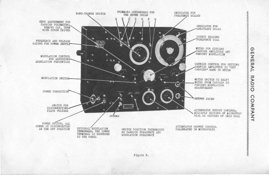
The Type 605-A Standard-Signal Generator is simple to operate. All dials, knobs and ·switches are clearly marked on the front panel. Additional instructions will be found in Figure 3 and all of the essential details should be evident after reading the foregoing sections of this book.
3.3 PRECAUTIONS
Always turn back the CARRIER rheostat in a counterclockwise direction when the frequency of the oscillator is to be changed, and be sure the METER READS switch is set to the CARRIER position. In addition, when using carrier frequencies below 300 kc, set the modulation switch to the NORMAL position. These precautions are necessary to prevent overloading of the oscillator tube. At 50 kilocycles, for instance, the oscillator will deliver the proper voltage and cause the meter to deflect to the SET CARRIER mark with about 30 volts plate voltage applied by the CARRIER potentiometer. With the CARRIER potentiometer turned all the way over in a clockwise direction the plate voltage will be 175 volts and the tube will be overloaded and damaged if run for a considerable time. This condition will be noticed immediately by the fact that the carrier meter is deflected off scale.
- 5 -

GENERAL RADIO COMPANY
3.4 FREQUENCY
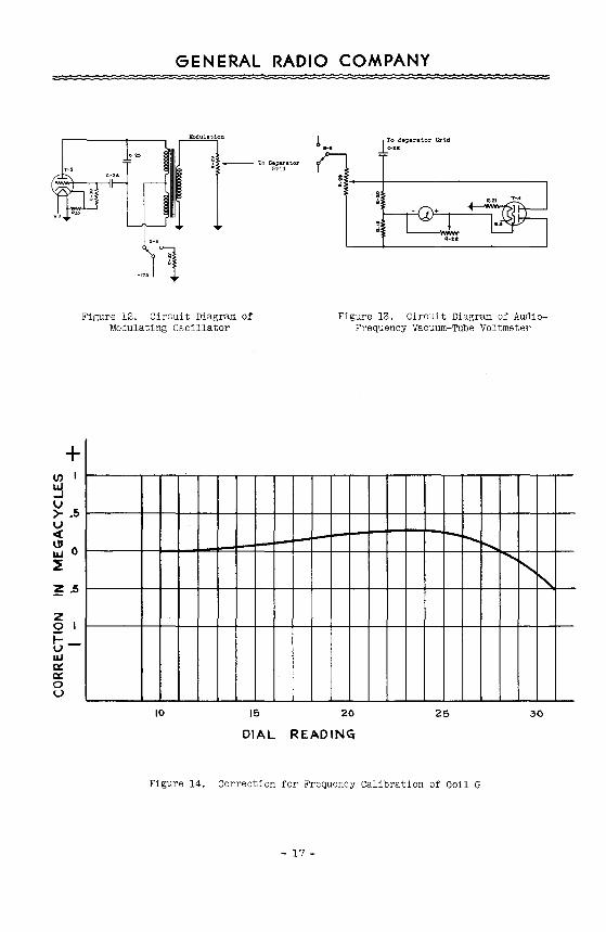
The desired frequency is set by selecting the proper coil with the band change switch and turning the direct reading frequency dial so that the desired frequency appears under the ce~luloid indicator. All frequencies in the normal range of the instrument are correct within 1% with the exception of the frequencies of Coil G for whi~h a correction curve is shown in Figure 14. The frequency of Coil H (30 to 50 Me) is not direct reading. A caiibration is given on page ll together with operating instructions.
3.5 SHITCH POSITIONS
After making sure that the CARRIER control is in counterc~ockwise position, the METER REAilS swi tell in the CARRIER position, the MODULATION switch on OFF, and the second modulation. switch in the NORMAL position. the POWER switch is put in the ON position. The pilot light will light immediately and in a short time, after the heaters of the tubes have come to temperature, the instrument will be in operating condition when the PLATE switch is in the ON position. This switch has been provided to interrupt oscillations of the standard-signal generator during receiver testing without allowing. the heaters of the tubes to cool.
3.6 OUTPUT VOLTAGE
3.61 Zero Position Adjustment
With all power off, the indicating meter should read zero. A zeroadjustment is provided in the meter itself.
3.62 Electrical Zero Adjustment
With the POWER switch in the ON position and PLATE switch OFF, the meter will show a small deflection which should go back to zero after the PLATE switch is thrown to the ON position. If, after the cathode heaters have reached operating temperature, the meter does not return to zero,. remove the small cap on the panel above the MODULATION switch, and readjust R24 with a screw driver (see paragraph 2.23). These adjustments have been made at the factory and usually will require no attention.
3.63 Output Level Adjustment
Advance the CARRIER control until the meter is set on the SET CARRIER mark. The output voltage of the CONSTANT
1-VOLT output jack is then exactly 1 volt and the output voltage of the lower output jack is read directly from the two attenuator dials.
3.7 MODULATION
3.71 Internal
For internal 400-cycle modulation, set the MODULATION switch to INTERNAL and the METER READS switch to MODULATION. Adjust the MODULATION control until the meter reads the desired percentage modulation.
3.72 External
Set the upper MODULATION switch to EXT. and the lower switch to EXTERNAL MOD. Connect an external audio-frequency source to the EXTERNAL MOD. terminals. Adjust for desired percentage modulation by means of MODULATION control.
3.721 Power Requirements and Filtering
For modulation frequencies between 30 and 15,000 cycles per second the input impedance of the external modulation binding posts is 2500 ohms and approximately 5 volts modulation voltage is required for 30 per cent modulation. The modulation circuit is well filtered for radio frequencies and at carrier frequencies above 300 kc no special precautions need be taken to prevent pickup from the leads connecting to the external m~dulation binding post.
3.722 Frequency Limits
As pointed out in the discussion of the separator circuit under operating principles, carrier frequencies below 300 kilocycles cannot be produced in the EXTERNAL MOD. position of the lower modulation switch. If this switch is in the NORMAL position, carrier frequencies down to 10 kilocycles can be produced, but the external modulation frequency should be limited to values below 1000 cycles. At higher external modulation frequencies, the output of the signal generator will contdin a relatively large amount of modulation frequency in addition to the modulated carrier voltage. It will be found that the meter will indicate this external modulation voltage with the METER READS switch in the CARRIER position and the CARRIER control set at zero.
- 6 -
GENERAL RADIO COMPANY
3.8 CONNECTIONS TO RECEIVER
Connection to the receiver under test is conveniently made by one of the two connectors supplied. They plug into the output jacks of the signal generator and are fitted with two clips on the other side. The plain lead is connected to ground, the lead with the red tracer to the high side of the circuit.
One connector is a concentric shielded rubber cable of 3-foot length with a characteristic impedance of 80 ohms and a capacity of 75 ~yf, approximately. The other connector has two separate leads of 2-foot length. The cable is intended for use in the lower output jack, the separate leads s~ouid be used in the CONSTANT 1-VOLT jack and in connection with high impedance dummy antennas.
When the lower output jack of the signal generator is used, the upper CONSTANT 1-VOLT jack alw~ys must be covered by the cap supplied to prevent any leakage.
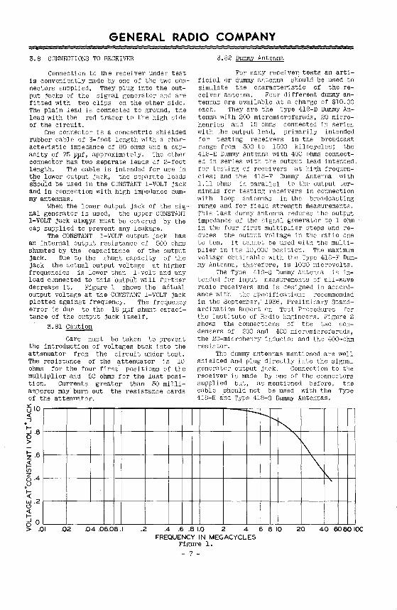
The CONSTANT 1-VOLT output jack has an internal output resistance of 500 ohms shunted by the capacitance of the output jack. Due to the shunt capacity of the jack the actual output voltage at higher frequencies is lower than l volt and any load connected to this ·output will further decrease it. Figure 1 shows the actual output voltage at the CONSTANT 1-VOLT jack plotted against frequency. The frequency error is due to the 16 ~~f shunt capacitance of the output jack itself.
3.81~
Care must be taken to prevent the introduction of voltages back into the attenuator from the circuit under test. The resistance of the ~ttenuator is 10 ohms for the four first· positions of the multiplier and 50 ohms for the last position. Currents greater than 50 milliamperes may burn out the resistance cards of the attennRicor.
i5 1.0 <(
·' t-5 .8 >
~ .6
~ (f)
6.4 .u ~ w .2 0 <(
3.82 Dummy Antenna
For many receive~ tests an artificial or dummy antenna should be used to simulate the characteristic of the receiver antenna. Four different dummy antennas are available at a charge of $10.00 each. They are the Type 418-D Dummy Antenna with 200 micromicrofarads, 20 microhenries and 15 ohms connected in series with the output lead, primarily intended for testing receivers in the broadcast range from 500 to 1500 kilocycles; the 418-E Dummy Antenna with 400 ohms connected in series with the output lead intended for testing of receivers at high frequencies; and the 418-F Dummy Antenna with l.ll ohms in parallel to the output terminals for testing receivers in connection with loop antennas in the broadcasting range and for field strength measurements. This last dummy antenna reduces the output impedance of the signal generator to l ohm in the four first multiplier steps and reduces the output voltage in the ratio one to ten. It cannot be used with the multiplier in its 10,000 position. The maximum voltage obtainable with the Type 418-F Dummy Antenna, therefore, is 1000 microvolts.
The Type 418-G Dummy Antenna is intended for input measurements of all-wave radio receivers and is designed in accordance with the specifications recommended in the September, 1936, Preliminary Standardization Report on Test Procedures for the Institute of Radio Engineers. Figure 2 shows the connections of the two condensers of 200 and 400 micromicrofarads, the 20-microhenry inductor and the 400-ohm resistor.
The dummy antennas mentioned are well shielded and plug directly into the signal generator output jack. Connection to the receiver is made by one of the connectors supplied but, as mentioned before, the cable should not be used with the Type 418-E and Type 418-G Dummy Antennas. -......._
'"-.,
"' \ \
t:i 0 ~ .01 .02 .04 .06.08.1 .2 .4 .6 .8 1.0 2 4 6 8 10 20 40 6080 IOC
FREQUENCY IN MEGACYCLES Figure l. - 7-

GENERAL RADIO COMPANY
o----------------0
3.9 HIGH FREQUENCIES
At high radio frequencies, antenna characteristics cannot easily be reproduced and considerable care must be taken in making receiver sensitivity tests. The voltage available at the signal generator output jack is always known, but not the voltage at the receiver input terminals ~ few feet away. This latter voltage is proportional to th& signal generator output voltage but it may be larger or smaller due to the characteristic and the termination of the "transmission line" between the instruments repr~sented by the output cable.
4.0 MAINTENANCE
The only parts of the Type 605-A Standard-Signal Generator which are subject to wear or deterioration and which require periodical attention are the vacuum tubes, the band change switch and the slide-wire combination associated with the MICROVOLTS dial. In addition, and as a result of ageing or excessive temperature variation, the calibration of the inductors may show slight drifts.
4.1 MAJOR REPAIRS
Fuses have been provided in ~he instrument to prevent serious damage if parts of the circuit should be short circuited. Condenser breakdown is one example of this type of failure. In such cases repairs are usually made at the factory.
4.2 DISASSEMBLY
To remove the instrument from the cabinet, remove all panel screws and disconnect the plug-in cable between the signal generator and the power supply.
4.3 VACUUM TUBES
The locations of the five vacuum tubes are given in paragraph 3.11. Following are instructions for readjusting, if necessary, the different circuits after changing the tubes. Operating voltages are given as measured at the socket terminals. vacuum tube symbols T1, T2 etc. refer to the wiring diagram. All d-e-voltages are measured with a Weston Type 772 Analyzer unless otherwise noted. Power frequency voltages must be measured with an accgrate r-m-s instrument. Copper-oxide rectifier-type meters would give erroneous readings because the voltage-regulating transformer in the Type 605-Pl Power Supply produces a distorted waveform. Audio-
frequency voltages may be measured with a copper-oxide meter. Radio-frequency voltage should be measured with a General Radio Type 726-A vacuum-Tube Voltmeter. All voltages given are approximate except the r-f voltage on the grid of T3 and the audio-frequency voltage across the plates of Ta_.
4.31 Carrier Oscillator
The only requirement to be met by the 76-type carrier oscillator tube is that it give sufficient output for operation over the complete frequency range of the instrument. The most critical point is at a frequency of 10 megacycles on Coil G where the highest plate voltage is used. The radio-frequency carrier voltage delivered to the grid of the separator tube must be about 3 volts for coils B, c, D, E and F and somewhat more for coils A and G. Since the tuning condenser has a high zero capacitance, changing the oscillator tube ordinarily will not affect the frequency calibration. Any change will be most noticeable at the high-frequency e·nd of each coil where compensation can be made by means of the trimming condensers. These are accessible from the front panel, after_removing the short hexagonal bolts indicated in Figure 3. Under normal operation, when the CARRIER control is advanced until the meter on the panel indicates at the SET CARRIER position, the plate current for the 76-type carrier oscillator is less than 3 milliamperes d-e for ranges A-B-C-D-E and F and is less than 10 milliamperes d-e for ranges G and H.
The approximate voltages appearing at the carrier oscillator tube socket under normal operating conditions are as follows:
Heater: 5.8 volts, r-m-s or d-e.
- 8 -
GENERAL RADIO COMPANY
Plate to Ground:
Frequency Range
A,G,H B,C,D,E,F
Less than 160 Less than 50
Except when checking coil continuity, it is recommended that these voltages be measured between the slider on R-17 (CARRIER control) and ground.
4.32 Separator
The 89-type separator tube with shield and grid cap can be replaced without affecting the accuracy of the frequency calibration or of the output level. This tube is working satisfactorily when one volt is produced across the 500-ohm plate output resistance.
The approximate voltages and currents appearing at the separator tube socket under normal operation are as follows:
Heater: 5.8 volts, r-m-s or d-e. ~o-Ground: 155 volts d-e at about 9 milliamperes. Screen Grid-to-Ground: 175 volts d-e at about 1,5 milliamperes. Control Grid- to-Ground: -24 volts d-e through a high resistance. A direct measurement with a 20 k!lper volt voltmeter of 50 volts full scale will indicate about -12 volts d-e.
4.33 Carrier Vacuum-Tube Voltmeter
The 955-type vacuum tube used in this circuit determines the accuracy of the output voltage and should be checked periodically since the emission current changes ·somewhat with age. Compensation for this effect can be made by readjusting the plate current balance as explained in paragraph 3.62. This readjustment will not affect the accuracy of the meter indication for a considerable range but it will eventually be necessary to readjust R23 which determines the sensitivity of the meter. With an old tube that has very low emission this adjustment will be impossible and the tube should be replaced.
4.331 Procedure
The procedure carrier vacuum-tube voltmeter lows:
in adjusting is as fol-
Set meter zero with meter adjusting screw with all power off.
After both filament and plate power have been on for about 5 minutes, with the METER READS switch on CARRIER and the CAR-
RIER control set at zero, set meter zero again with screw driver through front panel.
connect an accurate high-impedance ~olt
meter between ground and the grid of the 955-type tube (or the rear end of the mica resistance card R6) and advance CARRIER control until this voltmeter reads exactly one volt. The frequency of the CARRIER oscillator for this measurement should be low in order to avoid errors due to the leads connecting to the external meter. The MODULATION switch must be set in the OFF position and the lower modulation switch in the NORMAL position. At 10 kilocycles a high-impedance copper-oxide rectifier-type meter can be used but it should be borne in mind that the accuracy of the signal generator output will be no better than the accuracy of the meter with which this adjustment has been made. The Type 726-A vacuum-Tube Voltmeter is recommended.
With the external meter reading one volt, the shunt resistor R23 across the microammeter is adjusted to make the pointer come exactly to the SET CARRIER mark. This resistor is located at the rear center of the amplifier shelf and is locked by a flat-head screw. After resetting R23, this screw should be locked again and care must be exercised to be sure the rheostat arm does not move when this is done. Under normal operation, the plate-to-ground voltage is about 30 volts d-e, with a plate current of about 70 microamperes.
The approximate voltages appearing at the carrier vacuum-tube voltmeter socket under normal operating conditions are as follows:
Heater: 5.8 volts, r-m-s or d-e. Plate-to-Ground: 30 volts d-e. cathode-to-Ground: 1.5 volts d-e.
4.34 Modulation Oscillator
The 76-type tube used in the modulating oscillator should be replaced when it is no longer possible to obtain sufficient 400-cycle voltage to give 50% internal modulation with the MODULATI~N control set at maximum. A good tube will produce about 8 volts across the modulation potentiometer R29 . The plate voltage is approximately 170 volts d-e at about 2.7 milliamperes.
The approximate voltages appearing at the modulation-oscillator tube socket under normal operating conditions are as follows: Heater: 5.8 volts, r-m-s or d-e. Plate-to-Ground: 170 volts d-e
- 9 -
GENERAL RADJO COMPANY
4,35 Audio-Frequency Vacuum-Tube Voltmeter
If the 84-type audio-frequency voltmeter tube is replaced, readjustment of the 10,000-ohm shunt rheostat R22 may be necessary. This rheostat is located on the right-hand side of the amplifier sr.elf and is set to make the indicating meter read 40% with 5 volts audio frequency applied between the arm of the modulation potentiometer R29 and ground.* An audio-frequency voltage for this test is most conveniently obtained from the internal modulation oscillator by setting the MODULATION switch to INTERNAL and reading the voltage on an accurate high-impedance voltmeter connected between the arm of R29 and ground. For this test the METER READS switch must be set to the MODULATION position.
The heater for this tube is operated at a 1·ow temperature. Heater voltages are approximately 5.8 volts (r-m-s or d-e) !or one heater terminal to ground and approximately 3.0 volts for the other heater terminal to ground.
4.36 Power Supply Rectifier
The 84-type rectifier tube in the Type 605-Pl Power Supply should deliver 37 milliamperes at 200 volts. To test this voltage with the signal generator disconnected the plate switch should be in tho OFF )osition. This will substitute the 5000-ohm resistor R3 for ohe plate load of the signal generator. CAUTION: IF THE PLUG CONNECTED BETWEEN THE POWER SUPPLY AND THE SIGNAL GENERATOR IS REMOVED, NEVER TURN ON THE POWER SWITCH UNLESS THE PLATE SWITCH IS IN THE OFF POSITION. O~HERWISE THE POWER SUPPLY-wiLL BE SERIOUSLY DAMAGED BECAUSE THE VOLTAGE DELIVERED BY THE POWER TRANSFORMER REACHES A SUFFICIENTLY HIGH VALUE TO ARC ACROSS THE FILTER CONDENSERS. A 4.2-ohm external resistor should be placed between terminal 4 of the power transformer and the arm of rheostat R4 to simulate the load o~ the vacuum-tube cathode heaters, The voltage between the OUT terminals of the Type 732-24 Filter Assembly and terminal 7 of the power transformer should be 200 volts and the voltage across the 650-ohm resistor R1 should be 25 volts. Both these voltages must be measured with high-resistance voltmeters drawing less than 1 milliampere. ·
*For a more accurate setting, the actual percentage modulation of the standard-signal generator should be checked by some other means, a cathode-ray tube or a modulation meter, since variations in the chara,cteristic of the T:ype 89 Separator Tube may require a modulation voltage dii'ferent !'rom the average voltage given in 2.26.
The voltage appearing across the heater of the 84-type rectifier tube (and across the pilot lamps) is approximately 5.8 volts r-m-s. A true r-m-s meter must be used. A copper-oxide type of meter will give a false indication.
4, 4 BAND CHANGE SWITCH
The band change switch and the two rheostats of the slide wire combination may after long use become erratic in operation as a result of dust accumulating on the contacts. When this occurs these should be carefully cleaned with a dry cioth.
4.5 FREQUENCY CALIBRATION
A drift in the frequency calibration can be corrected by changing the inductance and capacitance values in the 7 tuned circuits. Each circuit is provided with a trimming condenser and an ldjustable iron core. The core of Coil A consists of narrow strips of transformer iron glued together and supported by a 1 ong screw through the bottom of the shelf. Au justment of this coil is made by turning the core after the lock nut on the bottom has been loosened. Coils B to G have dust cores held in place by 2 setscrews. After loosening these, the dust cores can be moved.
4.51 Resetting of the trimming condensers, which can be easily done from the outside without removing the instrument from the cabinet, will change the frequency at the high-frequency end of each coil much more than at the low-frequency end. Changing the inductance or a coil by moving the iron core will affect both ends of the range equally.
4.52 The cores can be readjusted only after the instrument is taken out of the cabinet and the three-sided shield of the oscillator unit has oeen removed. Since this shield also affects the frequency of the oscillator it should be replaced after each adjustment before measuring the frequency. It will be sufficient for this purpose to replace only one or two of the 24 screws.
4.53 The quickest way to adjust a coil is to set first the low-frequency end by moving the iron core at a setting of the tuning condenser dial of 10, for coils A; C, E, and G and 30 for coils B, D, and F. Whan this is done the high-frequency end of the coil should be set by means of the trimming condenser at a setting of the tuning condenser dial of 30 or 90 respectively. If the adjustment o.f the tri.mming condenser ls changed appreciably, it will
- 10 -
GENERAL RADIO COMPANY
be advisable to recheck the low frequency end and to repeat the same procedure until the frequencies at both ends of the coils are correct.
4.54 .The frequency at an intermediate setting of the tuning condenser dial should then be well within l per cent. of the calibrated value, with the exception of Coil G for which corrections are shown in Figure 14. These intermediate frequen-
cies depend on the shape of the tuning condenser plates and on the accuracy with which the condenser has been assembled. If an intermediate frequency differs more than l% from the calibrated value on one coil, it will be found that the same error exists on all other coils. In that case the tuning condenser has been damaged and the instrument should be returned to the factory for repair.
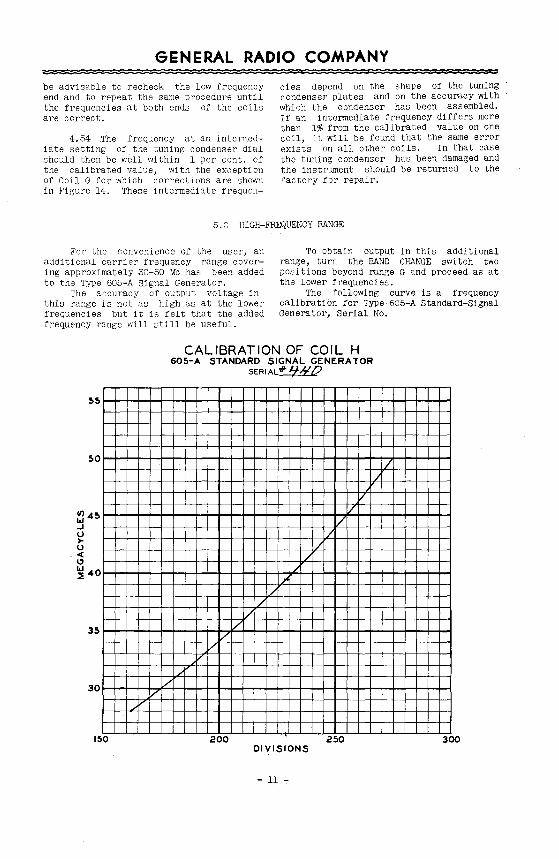
5.0 HIGH-FREQUENCY RANGE
For the convenience of the user, an additional carrier frequency range covering approximately 30-50 Me has been added to the Type 605-A Signal Generator.
The accuracy of output voltage in this range is not as high as at the lower frequencies but it is felt that the added frequency range will still be useful.
To obtain output in this additional range, turn the BAND CHANGE switch two positions beyond range G and proceed as at the lower frequencies.
The following curve is a frequency calibration for Type 605-A Standard-Signal Generator, Serial No.
CALIBRATION OF COIL H 605-A STANDARD SIGNAL GENERATOR
SERIAL0!LL?
55
50
~45 .J 0 >-0 <( C)
~40
35
30
150
i/ /
/ v
I/ v
200
/ /
v 1/
/ /
/ J'
/ /
250 300 DIVISIONS
- 11 .,.
GENERAL RADIO COMPANY
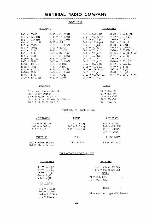
PARIS LIST
RESISTORS
R-1 ~ 500Jl R-2 = 0.1 MJl R-3 = 0.2 MJl R-4 = 50, OOOJl R-5 ~ 2000.52 R-6 = 450.52 R-7 = 50Jl R-8 = 95Jl, R-9 ; 95Jl. R-10 = 11. 7.Q R-11 = 99.fl R-12; 12. 2-R R-13; 99~ R-14 = 12. 2.Q R-15 = 99.fl R-16 = 11Jl. R-17- 10, ooo.n.
SvJITCHES
R-18 = 20,000.11 R-19 = 15, OOO.ll. R-20 = 15, 0005). R-21 = 8.n R-22 = lO,OOOJl. R-23 = 2500Sl R-24 = lOOO.Q R-25 = 0.1 MSl. R-26 = 20, 000.11 R-27 = 500Sl. R-28 = 10,ooo.n. R-29 = 25005). R-30 = 2 M.ft R-31 = 0. 5 M.ll R-32 = 50. 000.11. R-33; 750-fl R-34 = 500 J1.
Sl =Band Change Switch S2 - Meter Switch S3 =Modulation Switch S4 = External Modulation Switch S5 = Multiplier Switch
CONDENSERS
C-1 - 0.02 )lf C-2 = 0. 005 yf C-3 - 0.02 yf C-4 = 1400 }l)lf C-5 = 10 ppf c-s = 70 yyr C-7 = 70 ypf C-8 = 70 p)lf C-9 = 10 ypf C-10 = 10 yyf C-11 = 10 )l)lf C-12 = 0. 02 Jlf C-13 = 0.02 )lf c-14 = 17-22 ppr c-15 ~ 15 yy.r c-16 = o.ooo5 yr c-17 = o.o2 yr
C-18 = 0.0005 yf C-19 = 0. 005 yt C-20 = 0. 02 yt C-21 = 0.02 )lf C-22 = l. 0 yf C-23 = 0. 00025 )lf C-24 = 0. 00025 yt C-25- 0. 25 yf _:!: 5% C-26 = 0.02 yf C-27 - 0. 002 Jlf c-28 = o. oo1 yr C-29 = 0. 001 pf C-30 = 0.1 yt C-31 = 0.1 )lf C-32 = 0.1 yf C-33 = 0.25 yf! 5%
Tl = RCA-76 T2 = RCA-89 T3 = RCA-955 T4 = RCA-84 T5 = RCA-76
TYPE 605 Pl POWER SUPPLY
CONDENSERS
C-1 = 0.002 )lf c-2 = o. 002 yr C-3 = l yf
SWITCHES
S-1 =Power Switch S-2= Plate Switch
CONDENSERS
c-1= 0.1 yr C-2 == 0.1 yf C-3= 0.1 yf c-4= 1 pr C-5 = 2 yf
RESISTORS
R-1 = 0. 75Sl. R-2 = lOOO.ll. R-4 = 0.5 M.ft R-5 = 650.R
F-1 = 2.5 amp. F-2"" 2.5 amp. F-3 = 0.1 amp.
Tl = RCA-84
RESISTORS
R-l = 650Sl R-2 = 0.5 MJ). R-3 = 5000Jl. R-4 = 1.5.5<.
PILOT LAMP
Pl =5-6 volt
TYPE 605-PlO POWER SUPPLY
- 12 -
SWITCHES
S-l = Power Switch S-2 = Plate Switch
FUSES
Fl = 2.5 Amp, F2 = 0.1 Amp.
Ml =Weston, Type 006,200-BV.
(j) m z m ;:c > r ;:o MODULATION >
EXTERNAL rLUJUUL.AT.~UN TERlliNALS; THE LOWER TERIUNAL IS GROUNDED TO THE PANEL
SWITCH POSITION DETERMINED BY CARRIER FRE~UENCY AND ~ODULATION FREQUENCY
Figure 3.
0
0 ()
0 ~
ATTENUATOR OUTPUT CONTROL; ,> ~ULTIPLY SETTING OF MICROVOLT DIAL BY SETTING OF THIS DIAL Z
ATTENUATOR OUTPUT CONTROL CALIBRATED I N MICROVOLTS
-<
I
~
CANNI£N 0SC1Li .. /ITOR i-- ------ - - -- - - - -- - - - - - - --1
I I I I I I
I L __
I I I I
_ _j
1125
SEPARAro.R MKROVOLTS
~---------- s4-- -T--
II NOll e.rr. MOD. I
oz I I •
R7
R.'/4
CRIIRIER VTVM
L9
~
I _J
I
'I'
•
liB I I
Figure 4. Wiring Diagram for Type 60~A Standard-Signal Generator
.4?UL TIPLIER -----,
Rs Rl! IW
RIO 1112 Ill<
(j) m z m :;c > r-:;c > 0
0 n 0 ~ "'C > z -<
GENERAL RADIO COMPANY
CARRIER OSCILLATOR
AUDIOFREQUENCY VOLTMETER
SEPARATOR
AUDIOFREQUENCY MODULATING OSCILLATOR
Figure 5. Functional Diagram o1' Type 605-A Standard-Signal Generator
1 ~~~;/asR~
Cl 5th; ~~~:, 1 """''" ': !' :: A': OFF I I __:_____ ~~\ f:.L \ Tl
~~:~:: ~ CZ I ' ·~--.__J I I ___ j PI . ......
13 +II 14 -II 15 .fB ,,. -.8
Figure 6. Wiring Diagram for Type 605-Pl Power Supply
rz Ez
0 s, ~ .__c_ __ .,____,r----t>-----+-----,-
c,
Cz
~5 R4-c---r---±C4 -\M~I Figure 7. Wiring Diagram for Type 605-PlO Power SUPPly
- 15 -
GENERAL RADIO COMPANY
Figure 8. Schematic Circuit Diagram of carrier Oscillator
i'romtieparawr
Figure 10. Schematic Circuit of RadioFrequency Vacuum-Tube Voltmeter
From Oscillator
From Ext. ~ or Int. ~ llod.
•
To A-F VTVII
Figure 9. Schematic Circuit Diagram of Separator
From. Separator
To llult.
Output Jack
Figure 11. Circuit Diagram of Attenuator
-16-
+ U)
~ v >- .5 v c(
~ 0 l: ~ .5
z 01
t-uJ Ci! a: 0 u
GENERAL RADIO COMPANY
- To Separator Grid
! .... I To Separa t.or Grid ...J...C:-U
Figure 12. Circuit Diagram of Modulating Oscillator
Figure 13. Circuit Diagram of AudioFrequency Vacuum-Tube Voltmeter
-r---. ........ ........
~'-...
"
10 15 20 25 30
DIAL REAOIN~
Figure 14. Correction for Frequency Calibration of Coil G
- 17-