Embed Size (px)
Citation preview
GSM/EDGEDigital Standard forR&S®Signal GeneratorsOperating Manual
Oper
ating
Man
ual
(;ÕÂÄ<)1171.5254.12 ─ 14
Test
& Me
asur
emen
t
This document describes the following software options:
● R&S®AMU-K40/-K41/-K240/-K2411402.6106.02, 1403.0253.02, 1402.7602.02, 1403.0201.02
● R&S®SMATE-K40/-K411404.5107.02, 1404.8306.02
● R&S®SMBV-K40/-K41/-K240/-K2411415.8031.xx, 1415.8460.xx, 1415.8213.xx, 1415.8454.xx
● R&S®SMJ-K40/-K41/-K240/-K2411404.0305.02, 1409.2706.02, 1409.0510.02, 1409.2758.02
● R&S®SMU-K40/-K41/-K240/-K2411160.7609.02, 1408.7810.02, 1408.5518.02, 1408.7862.02
● R&S®SMW-K240/-K2411413.4739.02, 1413.4780.02
● R&S®AFQ-K240/-K2411401.6302.02, 1401.6102.02
● R&S®CMW-KW2001203.0951.02
● R&S®SFU-K240/-K2412115.2237.02, 2115.2243.02
© 2013 Rohde & Schwarz GmbH & Co. KGMühldorfstr. 15, 81671 München, GermanyPhone: +49 89 41 29 - 0Fax: +49 89 41 29 12 164E-mail: [email protected]: www.rohde-schwarz.comSubject to change – Data without tolerance limits is not binding.R&S® is a registered trademark of Rohde & Schwarz GmbH & Co. KG.Trade names are trademarks of the owners.
The following abbreviations are used throughout this manual: R&S®AMU200A is abbreviated as R&S AMU, R&S®SMATE200A isabbreviated as R&S SMATE, R&S®SMBV100A is abbreviated as R&S SMBV, R&S®SMJ100A is abbreviated as R&S SMJ,R&S®SMU200A is abbreviated as R&S SMU, R&S®SMW200A is abbreviated as R&S SMW, R&S®WinIQSIM2TM is abbreviated asR&S WinIQSIM2.
ContentsGSM/EDGE
3Operating Manual 1171.5254.12 ─ 14
Contents1 Preface.................................................................................................... 5
1.1 Documentation Overview............................................................................................. 5
1.2 Typographical Conventions.........................................................................................6
2 Introduction............................................................................................ 72.1 VAMOS (Voice services over Adaptive Multi-user channels on One Slot)..............8
3 GSM/EDGE User Interface...................................................................113.1 GSM/EDGE Main Menu............................................................................................... 11
3.2 Mode Unframed........................................................................................................... 16
3.3 Mode Framed (single)................................................................................................. 18
3.4 Mode Framed (double)................................................................................................20
3.5 Save Recall Frame/Slots.............................................................................................21
3.6 Modulation/Filter......................................................................................................... 23
3.6.1 General Settings........................................................................................................... 24
3.6.2 MSK/FSK Settings........................................................................................................ 25
3.6.3 AQPSK Settings............................................................................................................26
3.6.4 8 PSK / EDGE Settings.................................................................................................27
3.6.5 16QAM Settings............................................................................................................ 27
3.6.6 32QAM Settings............................................................................................................ 28
3.6.7 HSR QPSK Settings......................................................................................................28
3.6.8 HSR 16QAM Settings................................................................................................... 28
3.6.9 HSR 32QAM Settings................................................................................................... 29
3.7 Power Ramping/Slot Attenuation.............................................................................. 29
3.8 Trigger/Marker/Clock Settings................................................................................... 32
3.8.1 Trigger In.......................................................................................................................34
3.8.2 Marker Mode................................................................................................................. 38
3.8.3 Marker Delay.................................................................................................................39
3.8.4 Clock Settings............................................................................................................... 40
3.8.5 Global Settings..............................................................................................................41
3.9 Burst Editor................................................................................................................. 42
3.10 Slot Marker Definition................................................................................................. 55
ContentsGSM/EDGE
4Operating Manual 1171.5254.12 ─ 14
4 Remote-Control Commands............................................................... 594.1 Primary Commands.................................................................................................... 60
4.2 Save Recall Frame/Slots.............................................................................................68
4.3 Modulation/Filter Settings.......................................................................................... 73
4.3.1 Modulation Settings.......................................................................................................73
4.3.2 Filter Settings................................................................................................................ 77
4.4 Clock Settings............................................................................................................. 80
4.5 Trigger Settings...........................................................................................................83
4.6 Marker Settings........................................................................................................... 90
4.7 Power Ramping/Slot Attenuation.............................................................................. 96
4.8 Burst Editor................................................................................................................. 98
4.9 Slot Marker Definition............................................................................................... 109
List of Commands..............................................................................110
Index....................................................................................................113
PrefaceGSM/EDGE
5Operating Manual 1171.5254.12 ─ 14
1 Preface
1.1 Documentation Overview
The user documentation for the R&S Signal Generator consists of the following parts:
● Online Help system on the instrument,● "Quick Start Guide" printed manual,● Documentation CD-ROM with:
– Online help system (*.chm) as a standalone help,– Operating Manuals for base unit and options,– Service Manual,– Data sheet and specifications,– Links to useful sites on the R&S internet.
Online Help
The Online Help is embedded in the instrument's firmware. It offers quick, context-sen-sitive access to the complete information needed for operation and programming. Theonline help contains help on operating the R&S Signal Generator and all availableoptions.
Quick Start Guide
The Quick Start Guide is delivered with the instrument in printed form and in PDF for-mat on the Documentation CD-ROM. It provides the information needed to set up andstart working with the instrument. Basic operations and an example of setup are descri-bed. The manual includes also general information, e.g., Safety Instructions.
Operating Manuals
The Operating Manuals are a supplement to the Quick Start Guide. Operating Manualsare provided for the base unit and each additional (software) option.
These manuals are available in PDF format - in printable form - on the DocumentationCD-ROM delivered with the instrument. In the Operating Manual for the base unit, allinstrument functions are described in detail. Furthermore, it provides an introduction toremote control and a complete description of the remote control commands with pro-gramming examples. Information on maintenance, instrument interfaces and errormessages is also given.
In the individual option manuals, the specific instrument functions of the option aredescribed in detail. For additional information on default settings and parameters, referto the data sheets. Basic information on operating the R&S Signal Generator is notincluded in the option manuals.
Documentation Overview
PrefaceGSM/EDGE
6Operating Manual 1171.5254.12 ─ 14
Service Manual
The Service Manual is available in PDF format - in printable form - on the Documenta-tion CD-ROM delivered with the instrument. It describes how to check compliance withrated specifications, on instrument function, repair, troubleshooting and fault elimina-tion. It contains all information required for repairing the instrument by the replacementof modules.
This manual can also be orderd in printed form (see ordering information in the datasheet).
Release Notes
The release notes describe new and modified functions, eliminated problems, and lastminute changes to the documentation. The corresponding firmware version is indicatedon the title page of the release notes. The current release notes are provided in theInternet.
Web Helps
Web helps are provided for the base unit and each additional (software) option. Thecontent of the web helps correspond to the user manuals for the latest product ver-sions.
The web help is an additional file format that offers quick online access. They are notintended to be downloaded but rather to access the required information directly formthe R&S website.
Web helps are available at the R&S website, on the R&S Signal Generator productpage at the "Downloads > Web Help" area.
1.2 Typographical Conventions
The following text markers are used throughout this documentation:
Convention Description
"Graphical user interface ele-ments"
All names of graphical user interface elements on the screen, such asdialog boxes, menus, options, buttons, and softkeys are enclosed byquotation marks.
KEYS Key names are written in capital letters.
File names, commands,program code
File names, commands, coding samples and screen output are distin-guished by their font.
Input Input to be entered by the user is displayed in italics.
Links Links that you can click are displayed in blue font.
"References" References to other parts of the documentation are enclosed by quota-tion marks.
Typographical Conventions
IntroductionGSM/EDGE
7Operating Manual 1171.5254.12 ─ 14
2 IntroductionThe R&S Signal Generator equipped with option R&S SMx/AMU-K40 enables you togenerate signals in accordance with the GSM/EDGE standard, based on the GMSKand 8PSK modulation. Option R&S SMx/AMU-K41 EDGE Evolution extends the GSM/EDGE signal generation with simulation of higher order modulations (QPSK, 16QAMand 32QAM) for higher symbol rate bursts and higher order modulations (16QAM and32QAM) for normal symbol rate bursts.
GSM is a TDMA standard for cellular mobile radio networks and is used worldwide.The R&S Signal Generator is suitable as a signal generator for all GSM variants. Thereis no restriction regarding the use of GSM slots, EDGE slots and EDGE Evolutionslots.
The R&S Signal Generator can generate both the transmitter signal of a base station(BS) and the transmitter signal of user equipment (UE).
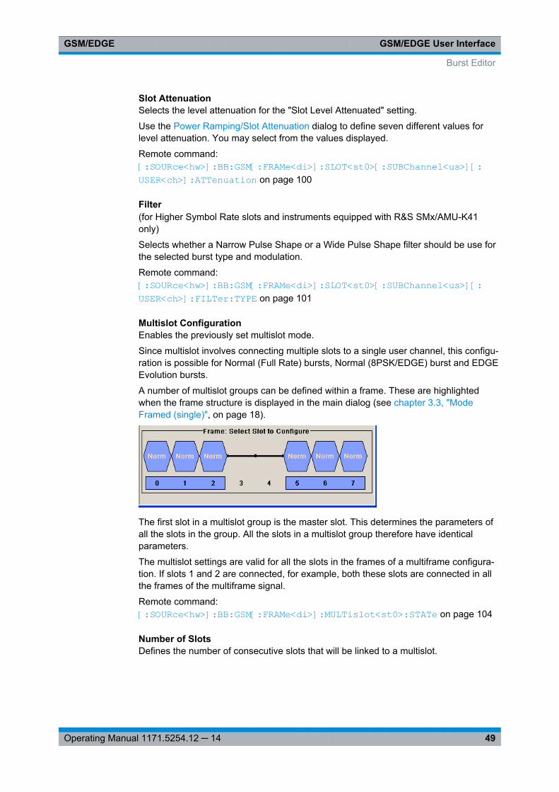
Every TDMA frame consists of 8 timeslots (or simply "slots"). Each slot can be sepa-rately turned on or off. A maximum of 7 different level attenuation values can bedefined and allocated separately to the 8 slots quite independently of one another.
In order to configure a slot it is necessary to define a burst type. Different burst typesare available, depending on the installed options on the instrument.
For instruments equipped only with optionR&S SMx/AMU-K40, you can choosebetween data bursts Normal (full rate and half rate) and EDGE; control bursts Access,Frequency Correction and Synchronization; a Dummy Burst; and bursts for test purpo-ses, All_Data (GSM and EDGE). Not only can you generate half rate slots but you canalso define multislots for HSCSD (high speed circuit switched data) and (E)GPRS(general packet radio service) configurations at the physical level, if necessary allocat-ing multiple slots to a single connection (channel banding).
The optionR&S SMx/AMU-K41 extends the available burst types with burst typesdefined for normal symbol rate and higher order modulation schemes such as the databurst Normal (16QAM and 32QAM) and All_Data (16QAM and 32QAM) as well as withthe burst types defined for higher symbol rates HSR (QPSK, 16QAM and 32QAM) andHSR All_Data (QPSK, 16QAM and 32QAM).
Higher symbol rates are achieved by reduction of the symbol period and employing ofhigher symbol rate bursts (HB) instead of the normal burst (NB). A normal burst con-tains 116 encrypted symbols and uses time slots with normal duration (156 or 157symbols long). The higher symbol rate bursts carry information on full rate packet traf-fic channels, contain 138 encrypted symbols and use time slots with reduced symbolduration (187 or 188 symbols long).
The option R&S SMx/AMU-K41 provides additionally the functionality to configure andgenerate burst for VAMOS operation. All_Data (AQPSK) and Normal (AQPSK) burstsfor full and half rate operation are available.
The modulation data is continuously inserted into the chosen slots (in realtime). In thisfashion the data generator uses a digital signal processor to generate a data streamcomplete with modulation data and control signals for power ramping.
This data stream is converted into I/Q signals in the modulation encoder.
IntroductionGSM/EDGE
8Operating Manual 1171.5254.12 ─ 14
The signal is processed depending on the configured modulation scheme and selectedsymbol rate mode:● In accordance with the GSM standard, the MSK modulation type is set by default to
a symbol rate of 270.833 ksymb/s and Gauss filtering. The symbol rate can bechanged in the instrument. FSK with adjustable span can also be used as the mod-ulation type.
● In accordance with the standard, in the case of EDGE slots the 8PSK modulationtype is set by default to 3/8( rotation at a symbol rate of 270.833 ksymb/s andGauss linearized filtering.
● In accordance to EDGE Evolution specifications (option R&S SMx/AMU-K41), theEDGE Evolution slots in a normal burst (NB) are 16QAM or 32QAM modulated at asymbol rate of 270.833 ksymb/s and Gauss linearized filtering. The EDGE Evolu-tion slots in a higher symbol rate bursts (HB) are QPSK, 16QAM or 32QAM modu-lated at a symbol rate of 325 ksymb/s and spectrally Narrow or Wide Pulse Shapefiltering.
● In accordance to VAMOS specifications (option R&S SMx/AMU-K41), the slots areAQPSK modulated at a symbol rate of 270.833 ksymb/s and Gauss linearized fil-tering.
Three modes for each the normal and the higher symbol rate mode are available forconfiguring a GSM/EDGE signal:● Mode Unframed - a signal with standard-compliant modulation parameters but
without slot and frame structure is generated.● Mode Frame (Single) - a signal consisting of a frame is generated; it is also possi-
ble to choose half rate bursts and to define multislots.● Mode Frame (Double) - a signal consisting of two frames is generated; the frames
are repeated according to a defined default.
2.1 VAMOS (Voice services over Adaptive Multi-userchannels on One Slot)
According to 3GPP TS 45.001, with VAMOS it is possible to serve two MS simultane-ously on the same physical resource. Thus the voice channel capacity in the CSdomain can be doubled.
Each of the two VAMOS users is assigned a so-called VAMOS subchannel, i.e. thephysical radio resource is split into two subchannels, one for each VAMOS user. Thetwo subchannels are separated in uplink and downlink via training sequences. For thispurpose 3GPP TS 45.002 defines two sets of Training Sequence Codes (TSC). OneVAMOS user/subchannel gets a training sequence from TSC set 1, the other from TSCset 2. This ensures that the two training sequences have a very low cross-correlation.All mobiles must support TSC set 1, but only mobiles explicitly indicating support forVAMOS must also support TSC set 2.
In the uplink two GMSK modulated signals interfere with each other and the base sta-tion receiver requires an advanced multi-user detection algoritm.
VAMOS (Voice services over Adaptive Multi-user channels on One Slot)
IntroductionGSM/EDGE
9Operating Manual 1171.5254.12 ─ 14
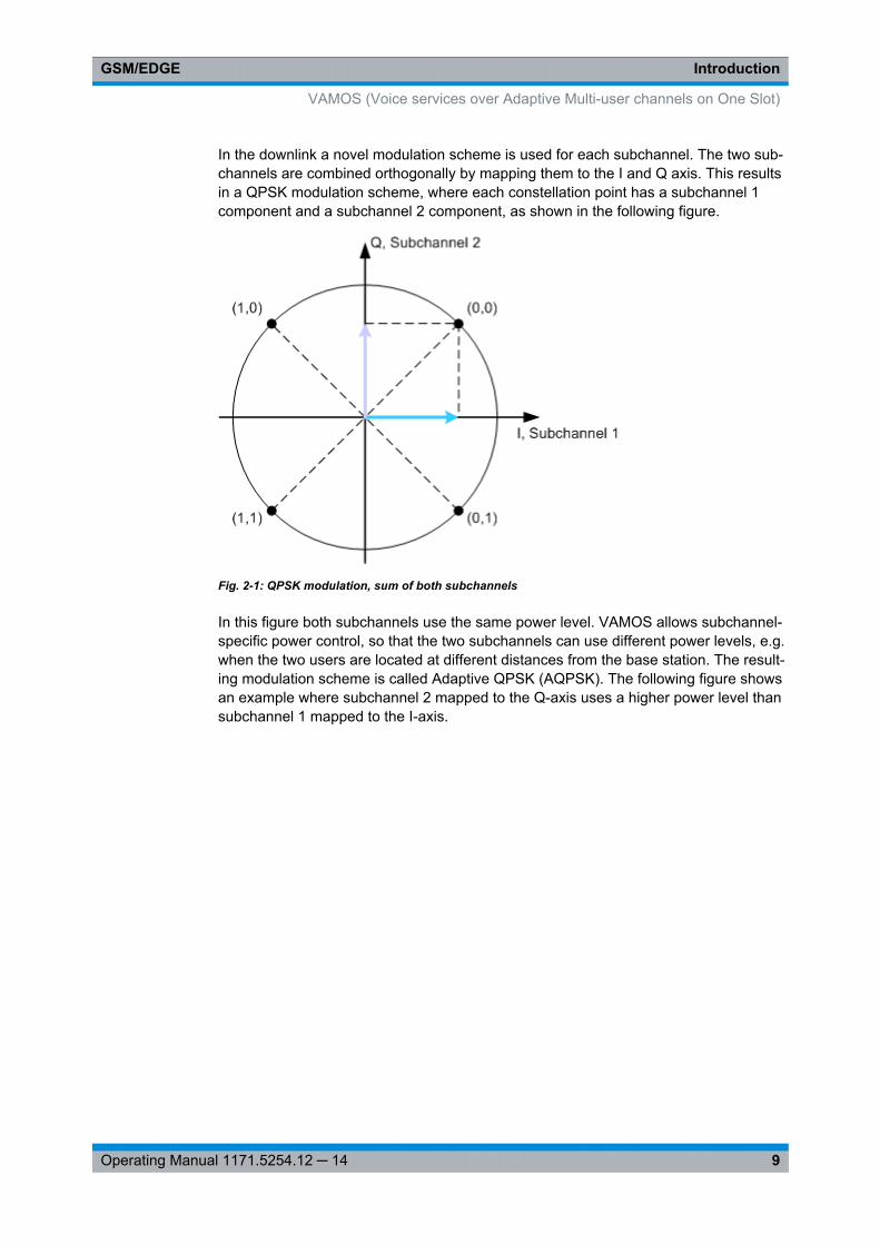
In the downlink a novel modulation scheme is used for each subchannel. The two sub-channels are combined orthogonally by mapping them to the I and Q axis. This resultsin a QPSK modulation scheme, where each constellation point has a subchannel 1component and a subchannel 2 component, as shown in the following figure.
Fig. 2-1: QPSK modulation, sum of both subchannels
In this figure both subchannels use the same power level. VAMOS allows subchannel-specific power control, so that the two subchannels can use different power levels, e.g.when the two users are located at different distances from the base station. The result-ing modulation scheme is called Adaptive QPSK (AQPSK). The following figure showsan example where subchannel 2 mapped to the Q-axis uses a higher power level thansubchannel 1 mapped to the I-axis.
VAMOS (Voice services over Adaptive Multi-user channels on One Slot)
IntroductionGSM/EDGE
10Operating Manual 1171.5254.12 ─ 14
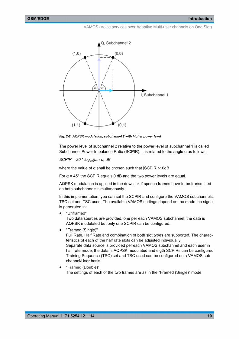
Fig. 2-2: AQPSK modulation, subchannel 2 with higher power level
The power level of subchannel 2 relative to the power level of subchannel 1 is calledSubchannel Power Imbalance Ratio (SCPIR). It is related to the angle α as follows:
SCPIR = 20 * log10(tan α) dB,
where the value of α shall be chosen such that |SCPIR|≤10dB
For α = 45° the SCPIR equals 0 dB and the two power levels are equal.
AQPSK modulation is applied in the downlink if speech frames have to be transmittedon both subchannels simultaneously.
In this implementation, you can set the SCPIR and configure the VAMOS subchannels,TSC set and TSC used. The available VAMOS settings depend on the mode the signalis generated in:● "Unframed"
Two data sources are provided, one per each VAMOS subchannel; the data isAQPSK modulated but only one SCPIR can be configured.
● "Framed (Single)"Full Rate, Half Rate and combination of both slot types are supported. The charac-teristics of each of the half rate slots can be adjusted individuallySeparate data source is provided per each VAMOS subchannel and each user inhalf rate mode; the data is AQPSK modulated and eigth SCPIRs can be configuredTraining Sequence (TSC) set and TSC used can be configured on a VAMOS sub-channel/User basis
● "Framed (Double)"The settings of each of the two frames are as in the "Framed (Single)" mode.
VAMOS (Voice services over Adaptive Multi-user channels on One Slot)
GSM/EDGE User InterfaceGSM/EDGE
11Operating Manual 1171.5254.12 ─ 14
3 GSM/EDGE User InterfaceTo access the dialog for setting the digital standard, select "Baseband block > GSM/EDGE" or use the dialog tree under "Baseband".
The screenshots provided in this description show parameter values that have beenselected to illustrate as much as possible of the provided functions and possible inter-dependencies between them.These values are not necessarily representative of realistic test situations.
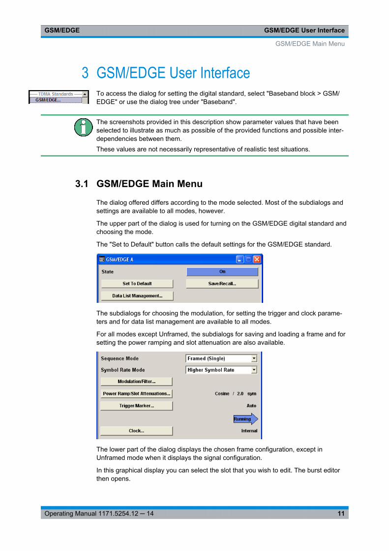
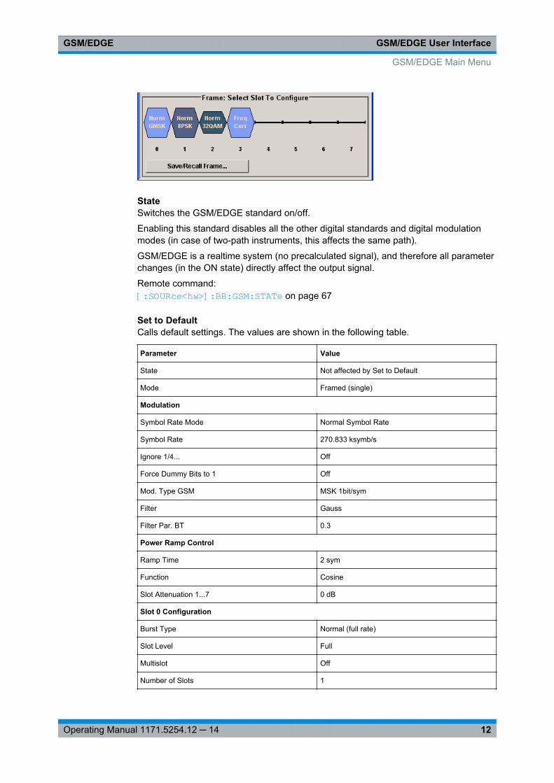
3.1 GSM/EDGE Main Menu
The dialog offered differs according to the mode selected. Most of the subdialogs andsettings are available to all modes, however.
The upper part of the dialog is used for turning on the GSM/EDGE digital standard andchoosing the mode.
The "Set to Default" button calls the default settings for the GSM/EDGE standard.
The subdialogs for choosing the modulation, for setting the trigger and clock parame-ters and for data list management are available to all modes.
For all modes except Unframed, the subdialogs for saving and loading a frame and forsetting the power ramping and slot attenuation are also available.
The lower part of the dialog displays the chosen frame configuration, except inUnframed mode when it displays the signal configuration.
In this graphical display you can select the slot that you wish to edit. The burst editorthen opens.
GSM/EDGE Main Menu
GSM/EDGE User InterfaceGSM/EDGE
12Operating Manual 1171.5254.12 ─ 14
StateSwitches the GSM/EDGE standard on/off.
Enabling this standard disables all the other digital standards and digital modulationmodes (in case of two-path instruments, this affects the same path).
GSM/EDGE is a realtime system (no precalculated signal), and therefore all parameterchanges (in the ON state) directly affect the output signal.
Remote command: [:SOURce<hw>]: BB:GSM: STATe on page 67
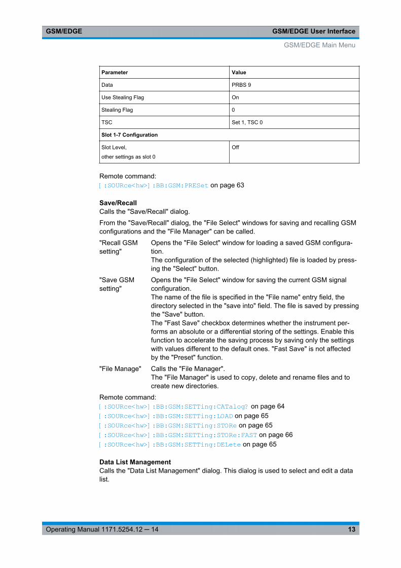
Set to DefaultCalls default settings. The values are shown in the following table.
Parameter Value
State Not affected by Set to Default
Mode Framed (single)
Modulation
Symbol Rate Mode Normal Symbol Rate
Symbol Rate 270.833 ksymb/s
Ignore 1/4... Off
Force Dummy Bits to 1 Off
Mod. Type GSM MSK 1bit/sym
Filter Gauss
Filter Par. BT 0.3
Power Ramp Control
Ramp Time 2 sym
Function Cosine
Slot Attenuation 1...7 0 dB
Slot 0 Configuration
Burst Type Normal (full rate)
Slot Level Full
Multislot Off
Number of Slots 1
GSM/EDGE Main Menu
GSM/EDGE User InterfaceGSM/EDGE
13Operating Manual 1171.5254.12 ─ 14
Parameter Value
Data PRBS 9
Use Stealing Flag On
Stealing Flag 0
TSC Set 1, TSC 0
Slot 1-7 Configuration
Slot Level,
other settings as slot 0
Off
Remote command: [:SOURce<hw>]: BB: GSM:PRESet on page 63
Save/RecallCalls the "Save/Recall" dialog.
From the "Save/Recall" dialog, the "File Select" windows for saving and recalling GSMconfigurations and the "File Manager" can be called.
"Recall GSMsetting"
Opens the "File Select" window for loading a saved GSM configura-tion.The configuration of the selected (highlighted) file is loaded by press-ing the "Select" button.
"Save GSMsetting"
Opens the "File Select" window for saving the current GSM signalconfiguration.The name of the file is specified in the "File name" entry field, thedirectory selected in the "save into" field. The file is saved by pressingthe "Save" button.The "Fast Save" checkbox determines whether the instrument per-forms an absolute or a differential storing of the settings. Enable thisfunction to accelerate the saving process by saving only the settingswith values different to the default ones. "Fast Save" is not affectedby the "Preset" function.
"File Manage" Calls the "File Manager".The "File Manager" is used to copy, delete and rename files and tocreate new directories.
Remote command: [:SOURce<hw>]: BB: GSM:SETTing: CATalog? on page 64[:SOURce<hw>]: BB: GSM:SETTing: LOAD on page 65[: SOURce<hw>]: BB: GSM:SETTing: STORe on page 65[: SOURce<hw>]: BB: GSM:SETTing: STORe:FAST on page 66[:SOURce<hw>]: BB: GSM:SETTing: DELete on page 65
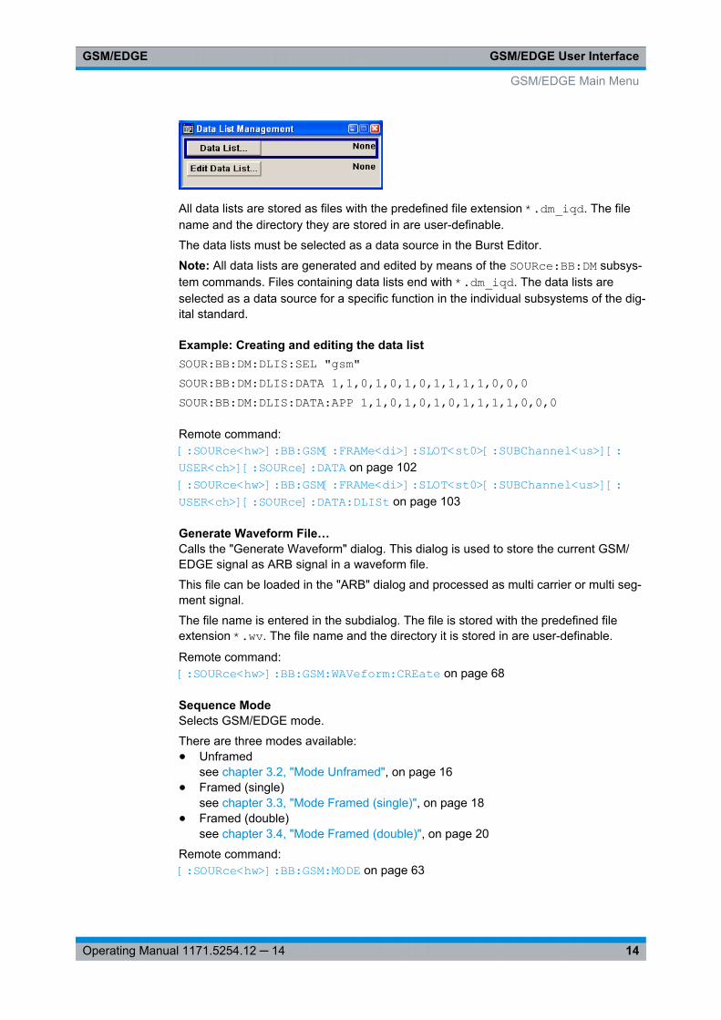
Data List ManagementCalls the "Data List Management" dialog. This dialog is used to select and edit a datalist.
GSM/EDGE Main Menu
GSM/EDGE User InterfaceGSM/EDGE
14Operating Manual 1171.5254.12 ─ 14
All data lists are stored as files with the predefined file extension *.dm_iqd. The filename and the directory they are stored in are user-definable.
The data lists must be selected as a data source in the Burst Editor.
Note: All data lists are generated and edited by means of the SOURce:BB:DM subsys-tem commands. Files containing data lists end with *.dm_iqd. The data lists areselected as a data source for a specific function in the individual subsystems of the dig-ital standard.
Example: Creating and editing the data listSOUR:BB:DM:DLIS:SEL "gsm"SOUR:BB:DM:DLIS:DATA 1,1,0,1,0,1,0,1,1,1,1,0,0,0SOUR:BB:DM:DLIS:DATA:APP 1,1,0,1,0,1,0,1,1,1,1,0,0,0
Remote command: [: SOURce<hw>]: BB:GSM[: FRAMe<di>]: SLOT<st0>[: SUBChannel<us>][: USER<ch>][: SOURce]: DATA on page 102[: SOURce<hw>]: BB:GSM[: FRAMe<di>]: SLOT<st0>[: SUBChannel<us>][: USER<ch>][: SOURce]: DATA: DLISt on page 103
Generate Waveform File…Calls the "Generate Waveform" dialog. This dialog is used to store the current GSM/EDGE signal as ARB signal in a waveform file.
This file can be loaded in the "ARB" dialog and processed as multi carrier or multi seg-ment signal.
The file name is entered in the subdialog. The file is stored with the predefined fileextension *.wv. The file name and the directory it is stored in are user-definable.
Remote command: [:SOURce<hw>]: BB:GSM:WAVeform: CREate on page 68
Sequence ModeSelects GSM/EDGE mode.
There are three modes available:● Unframed
see chapter 3.2, "Mode Unframed", on page 16● Framed (single)
see chapter 3.3, "Mode Framed (single)", on page 18● Framed (double)
see chapter 3.4, "Mode Framed (double)", on page 20
Remote command: [: SOURce<hw>]: BB:GSM:MODE on page 63
GSM/EDGE Main Menu
GSM/EDGE User InterfaceGSM/EDGE
15Operating Manual 1171.5254.12 ─ 14
Symbol Rate Mode(for instruments equipped with option K41 only)
Set the symbol rate mode, i.e. determines whether a normal bursts (NB) or higher sym-bol rate bursts (HB) will be generated.
Remote command: [:SOURce<hw>]: BB: GSM:SRATe: MODE on page 67
Sequence Length(For R&S WinIQSIM2 only)
Selects the sequence length of the arbitrary waveform file in the number of frames orsymbols.
For unframed "GSM Mode", the sequence length is set in number of symbols and innumber of frames for framed GSM mode respectively.
In case the "GSM Mode" is set to double framed, the sequence length of the generatedARB file is determined by the parameter "Frame Repetition" for both frames:
Sequence Length = Frame Repetition of Frame 1 + Frame Repetition of Frame 2.
Remote command: [: SOURce<hw>]: BB:GSM:SLENgth on page 61[: SOURce<hw>]: BB:GSM:FLENgth on page 61
Modulation/FilterCalls the "Modulation/Filter" dialog. The Modulation dialog is used for setting the modu-lation and filter parameters, see chapter 3.6, "Modulation/Filter", on page 23.
Remote command: n.a.
Power Ramping/Slot AttenuationsCalls the "Power Ramping/Slot Attenuation" dialog. This dialog is used to set the powerramping parameters and for setting values for the level attenuation in dB, see chap-ter 3.7, "Power Ramping/Slot Attenuation", on page 29.
The currently selected ramp function and ramp time are displayed.
Remote command: n.a.
Trigger/MarkerCalls the "Trigger/Marker/Clock" dialog.
This dialog is used to select the trigger source, configure the marker output signals andset the time delay on an external trigger signal, see chapter 3.8, "Trigger/Marker/ClockSettings", on page 32.
Remote command: n.a.
Execute TriggerExecutes trigger manually.
GSM/EDGE Main Menu
GSM/EDGE User InterfaceGSM/EDGE
16Operating Manual 1171.5254.12 ─ 14
You can execute the trigger manually only if you select an internal trigger source and atrigger mode other than "Auto".
Remote command: [:SOURce<hw>]: BB:GSM: TRIGger: EXECute on page 85
ClockCalls the "Trigger/Marker/Clock" dialog. This dialog is used to select the clock source,see chapter 3.8.4, "Clock Settings", on page 40.
Remote command: n.a.
3.2 Mode Unframed
In "Unframed" mode a modulation signal without slot or frame structure is generated.The modulated carrier without power ramping is often enough for initial tests, and incase the complete signal is not yet needed.
Since all the modulation parameters for the signal are conform to the standard, onlythe symbol rate mode (normal or higher symbol rate) and the modulation (MSK or FSKfor GSM, 8PSK EDGE for EDGE and 16QAM EDGE or 32QAM EDGE for EDGE Evo-lution) have to be selected. The symbol rate and filter configuration are set accordingly.
This mode can be used for quick measurements of the spectrum or signal quality (e.g.EVM).
The subdialogs for selecting the modulation (see chapter 3.6, "Modulation/Filter",on page 23), as well as the trigger, marker and clock (see chapter 3.8, "Trigger/Marker/Clock Settings", on page 32 ) are offered.
Mode Unframed
GSM/EDGE User InterfaceGSM/EDGE
17Operating Manual 1171.5254.12 ─ 14
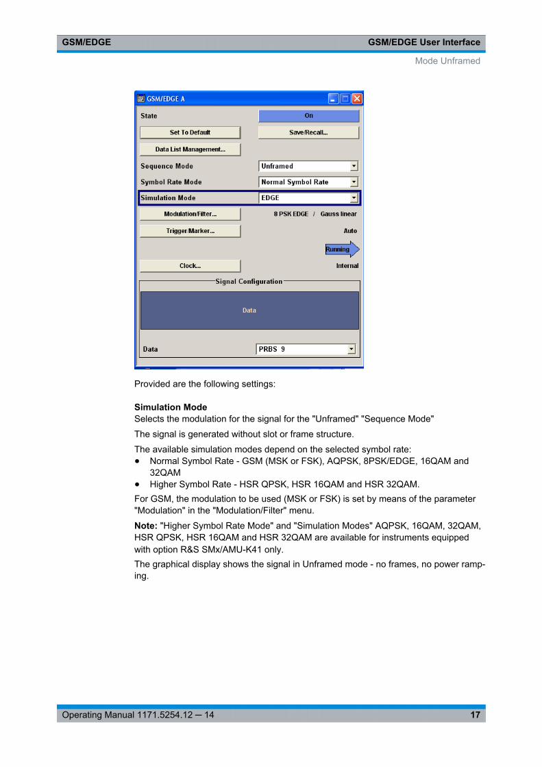
Provided are the following settings:
Simulation ModeSelects the modulation for the signal for the "Unframed" "Sequence Mode"
The signal is generated without slot or frame structure.
The available simulation modes depend on the selected symbol rate:● Normal Symbol Rate - GSM (MSK or FSK), AQPSK, 8PSK/EDGE, 16QAM and
32QAM● Higher Symbol Rate - HSR QPSK, HSR 16QAM and HSR 32QAM.For GSM, the modulation to be used (MSK or FSK) is set by means of the parameter"Modulation" in the "Modulation/Filter" menu.
Note: "Higher Symbol Rate Mode" and "Simulation Modes" AQPSK, 16QAM, 32QAM,HSR QPSK, HSR 16QAM and HSR 32QAM are available for instruments equippedwith option R&S SMx/AMU-K41 only.The graphical display shows the signal in Unframed mode - no frames, no power ramp-ing.
Mode Unframed
GSM/EDGE User InterfaceGSM/EDGE
18Operating Manual 1171.5254.12 ─ 14
Remote command: [:SOURce<hw>]: BB: GSM:SMODe on page 66
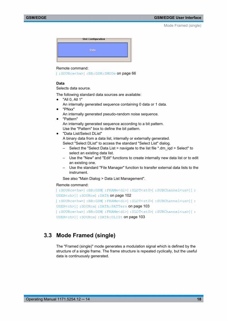
DataSelects data source.
The following standard data sources are available:● "All 0, All 1"
An internally generated sequence containing 0 data or 1 data.● "PNxx"
An internally generated pseudo-random noise sequence.● "Pattern"
An internally generated sequence according to a bit pattern.Use the "Pattern" box to define the bit pattern.
● "Data List/Select DList"A binary data from a data list, internally or externally generated.Select "Select DList" to access the standard "Select List" dialog.– Select the "Select Data List > navigate to the list file *.dm_iqd > Select" to
select an existing data list.– Use the "New" and "Edit" functions to create internally new data list or to edit
an existing one.– Use the standard "File Manager" function to transfer external data lists to the
instrument.See also "Main Dialog > Data List Management".
Remote command: [:SOURce<hw>]: BB:GSM[: FRAMe<di>]: SLOT<st0>[: SUBChannel<us>][: USER<ch>][: SOURce]:DATA on page 102[:SOURce<hw>]: BB:GSM[: FRAMe<di>]: SLOT<st0>[: SUBChannel<us>][: USER<ch>][: SOURce]:DATA: PATTern on page 103[:SOURce<hw>]: BB:GSM[: FRAMe<di>]: SLOT<st0>[: SUBChannel<us>][: USER<ch>][: SOURce]:DATA: DLISt on page 103
3.3 Mode Framed (single)
The "Framed (single)" mode generates a modulation signal which is defined by thestructure of a single frame. The frame structure is repeated cyclically, but the usefuldata is continuously generated.
Mode Framed (single)
GSM/EDGE User InterfaceGSM/EDGE
19Operating Manual 1171.5254.12 ─ 14
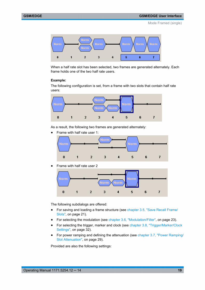
When a half rate slot has been selected, two frames are generated alternately. Eachframe holds one of the two half rate users.
Example: The following configuration is set, from a frame with two slots that contain half rateusers:
As a result, the following two frames are generated alternately:● Frame with half rate user 1:
● Frame with half rate user 2
The following subdialogs are offered:● For saving and loading a frame structure (see chapter 3.5, "Save Recall Frame/
Slots", on page 21).● For selecting the modulation (see chapter 3.6, "Modulation/Filter", on page 23).● For selecting the trigger, marker and clock (see chapter 3.8, "Trigger/Marker/Clock
Settings", on page 32).● For power ramping and defining the attenuation (see chapter 3.7, "Power Ramping/
Slot Attenuation", on page 29).
Provided are also the following settings:
Mode Framed (single)
GSM/EDGE User InterfaceGSM/EDGE
20Operating Manual 1171.5254.12 ─ 14
Save/Recall Frame …Access the "Save/Recall Frame" dialog for selecting of predefined or user definedframes, see chapter 3.5, "Save Recall Frame/Slots", on page 21.
Remote command: n.a.
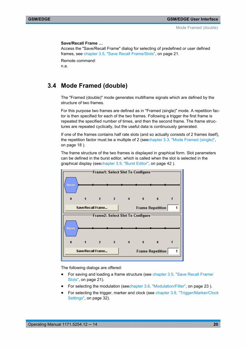
3.4 Mode Framed (double)
The "Framed (double)" mode generates multiframe signals which are defined by thestructure of two frames.
For this purpose two frames are defined as in "Framed (single)" mode. A repetition fac-tor is then specified for each of the two frames. Following a trigger the first frame isrepeated the specified number of times, and then the second frame. The frame struc-tures are repeated cyclically, but the useful data is continuously generated.
If one of the frames contains half rate slots (and so actually consists of 2 frames itself),the repetition factor must be a multiple of 2 (seechapter 3.3, "Mode Framed (single)",on page 18 ).
The frame structure of the two frames is displayed in graphical form. Slot parameterscan be defined in the burst editor, which is called when the slot is selected in thegraphical display (seechapter 3.9, "Burst Editor", on page 42 ).
The following dialogs are offered:● For saving and loading a frame structure (see chapter 3.5, "Save Recall Frame/
Slots", on page 21).● For selecting the modulation (seechapter 3.6, "Modulation/Filter", on page 23 ).● For selecting the trigger, marker and clock (see chapter 3.8, "Trigger/Marker/Clock
Settings", on page 32).
Mode Framed (double)
GSM/EDGE User InterfaceGSM/EDGE
21Operating Manual 1171.5254.12 ─ 14
● For power ramping and defining the attenuation (seechapter 3.7, "Power Ramping/Slot Attenuation", on page 29 ).
Provided are also the following settings:
Save/Recall Frame …Access the "Save/Recall Frame" dialog for selecting of predefined or user definedframes, see chapter 3.5, "Save Recall Frame/Slots", on page 21 .
Remote command: n.a.
Frame RepetitionEnters the number of repetitions for frame 1 or frame 2. First frame 1 is repeated thespecified number of times, and then frame 2, then frame 1 starts again, and so on.
Remote command: [:SOURce<hw>]: BB: GSM:FRAMe<di>: REPetitions on page 62
3.5 Save Recall Frame/Slots
The "Save/Recall Frame" dialog is accessed via the "GSM/EDGE" main dialog.
The "Save/Recall Slots" dialog is accessed via the "Burst Editor" dialog.
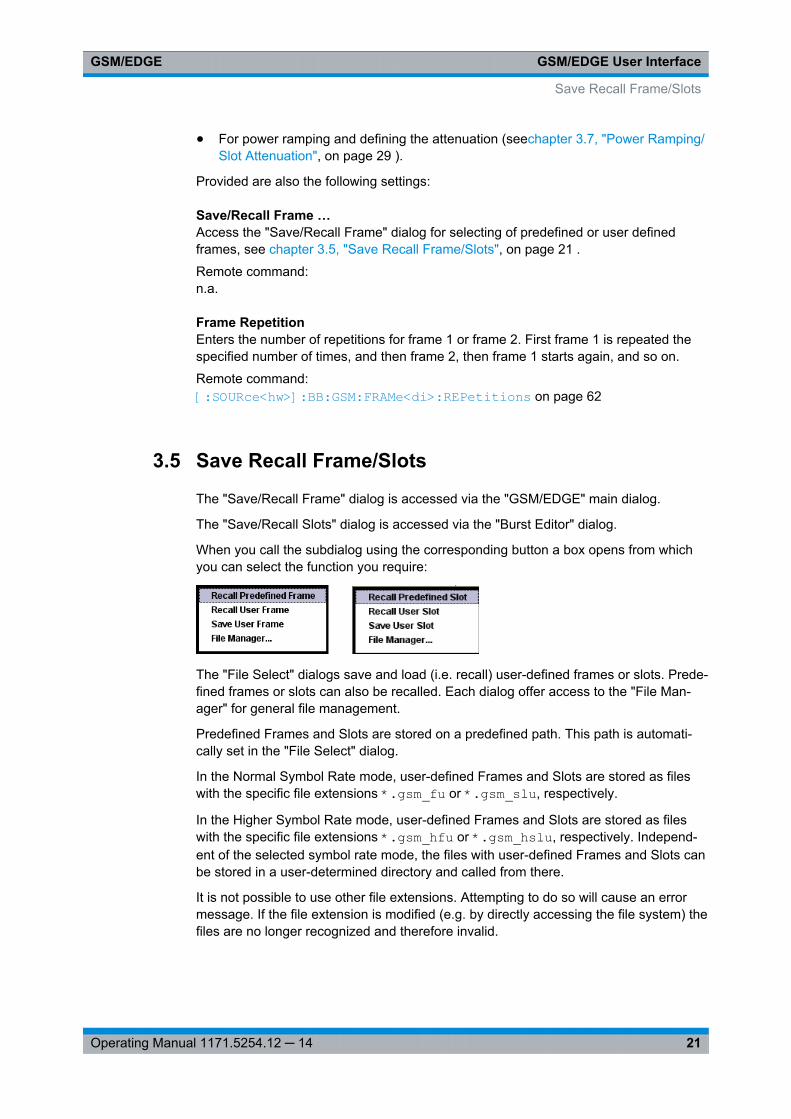
When you call the subdialog using the corresponding button a box opens from whichyou can select the function you require:
The "File Select" dialogs save and load (i.e. recall) user-defined frames or slots. Prede-fined frames or slots can also be recalled. Each dialog offer access to the "File Man-ager" for general file management.
Predefined Frames and Slots are stored on a predefined path. This path is automati-cally set in the "File Select" dialog.
In the Normal Symbol Rate mode, user-defined Frames and Slots are stored as fileswith the specific file extensions *.gsm_fu or *.gsm_slu, respectively.
In the Higher Symbol Rate mode, user-defined Frames and Slots are stored as fileswith the specific file extensions *.gsm_hfu or *.gsm_hslu, respectively. Independ-ent of the selected symbol rate mode, the files with user-defined Frames and Slots canbe stored in a user-determined directory and called from there.
It is not possible to use other file extensions. Attempting to do so will cause an errormessage. If the file extension is modified (e.g. by directly accessing the file system) thefiles are no longer recognized and therefore invalid.
Save Recall Frame/Slots
GSM/EDGE User InterfaceGSM/EDGE
22Operating Manual 1171.5254.12 ─ 14
In the following examples of commands the files are stored in the default directorywhich is defined by command MMEM:CDIRectory.
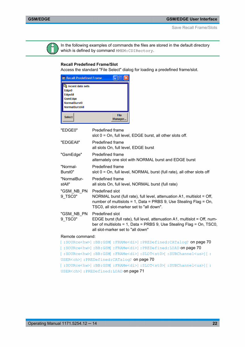
Recall Predefined Frame/SlotAccess the standard "File Select" dialog for loading a predefined frame/slot.
"EDGE0" Predefined frameslot 0 = On, full level, EDGE burst, all other slots off.
"EDGEAll" Predefined frameall slots On, full level, EDGE burst
"GsmEdge" Predefined framealternately one slot with NORMAL burst and EDGE burst
"Normal-Burst0"
Predefined frameslot 0 = On, full level, NORMAL burst (full rate), all other slots off
"NormalBur-stAll"
Predefined frameall slots On, full level, NORMAL burst (full rate)
"GSM_NB_PN9_TSC0"
Predefined slotNORMAL burst (full rate), full level, attenuation A1, multislot = Off,number of multislots = 1, Data = PRBS 9, Use Stealing Flag = On,TSC0, all slot-marker set to "all down".
"GSM_NB_PN9_TSC0"
Predefined slotEDGE burst (full rate), full level, attenuation A1, multislot = Off, num-ber of multislots = 1, Data = PRBS 9, Use Stealing Flag = On, TSC0,all slot-marker set to "all down"
Remote command: [:SOURce<hw>]: BB: GSM[:FRAMe<di>]: PREDefined: CATalog? on page 70[:SOURce<hw>]: BB: GSM[:FRAMe<di>]: PREDefined: LOAD on page 70[:SOURce<hw>]: BB: GSM[:FRAMe<di>]: SLOT<st0>[: SUBChannel<us>][: USER<ch>]: PREDefined: CATalog? on page 70[:SOURce<hw>]: BB: GSM[:FRAMe<di>]: SLOT<st0>[: SUBChannel<us>][: USER<ch>]: PREDefined: LOAD on page 71
Save Recall Frame/Slots
GSM/EDGE User InterfaceGSM/EDGE
23Operating Manual 1171.5254.12 ─ 14
Recall User Frame/SlotAccess the standard "File Select" dialog for loading a user-defined frame/slot.
Remote command: [:SOURce<hw>]: BB:GSM:FRAMe<di>: ULISt: CATalog? on page 68[:SOURce<hw>]: BB:GSM:FRAMe<di>: ULISt: LOAD on page 69[:SOURce<hw>]: BB:GSM[:FRAMe<di>]: SLOT<st0>[: SUBChannel<us>][: USER<ch>]: ULISt: CATalog? on page 71[:SOURce<hw>]: BB:GSM[:FRAMe<di>]: SLOT<st0>[: SUBChannel<us>][: USER<ch>]: ULISt: LOAD on page 72
Save User Frame/SlotAccess the standard "File Select" dialog for saving the current frame or slot settings.
Remote command: [: SOURce<hw>]: BB:GSM:FRAMe<di>: ULISt: STORe on page 69[: SOURce<hw>]: BB:GSM[: FRAMe<di>]: SLOT<st0>[: SUBChannel<us>][: USER<ch>]: ULISt: STORe on page 72
File ManagerAccess the standard "File Manager" dialog, used to copy, delete and rename files andto create new directories.
Remote command: [:SOURce<hw>]: BB:GSM: FRAMe<di>: ULISt:DELete on page 69[: SOURce<hw>]: BB:GSM[: FRAMe<di>]: SLOT<st0>[: SUBChannel<us>][: USER<ch>]: ULISt:DELete on page 72
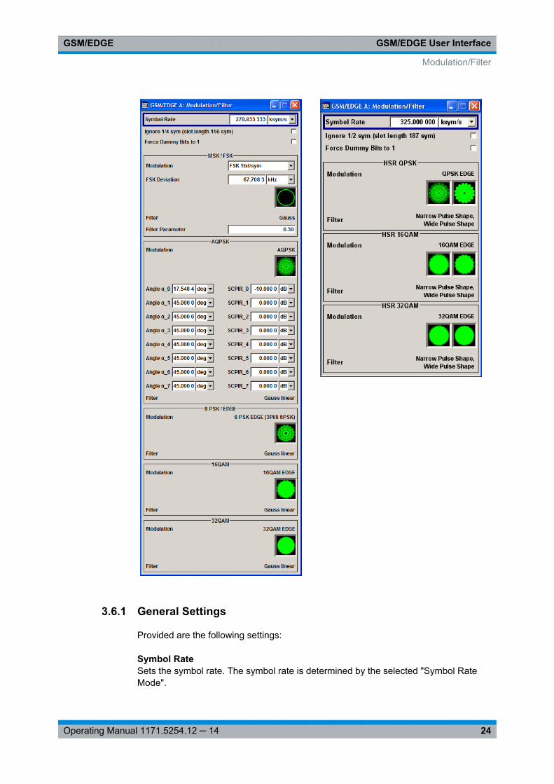
3.6 Modulation/Filter
The "Modulation/Filter" dialog is accessed via the "GSM/EDGE" main dialog.
The parameters displayed depend on the selected "Symbol Rate Mode". The parame-ters are grouped in different sections, according to the modulation (MSK/FSK, 8PSK/EDGE, QPSK, AQPSK, 16QAM or 32QAM) they apply to.
"Higher Symbol Rate Mode", AQPSK modulation and higher order modulations(16QAM and 32QAM) are available for instruments equipped with optionR&S SMx/AMU-K41 only.
Modulation/Filter
GSM/EDGE User InterfaceGSM/EDGE
24Operating Manual 1171.5254.12 ─ 14
3.6.1 General Settings
Provided are the following settings:
Symbol RateSets the symbol rate. The symbol rate is determined by the selected "Symbol RateMode".
Modulation/Filter
GSM/EDGE User InterfaceGSM/EDGE
25Operating Manual 1171.5254.12 ─ 14
For normal symbol rate mode, the default value for GSM/EDGE is 270.833 33ksymb/s.
For higher symbol rate mode, the default value for EDGE Evolution is 325 ksymb/s.
Remote command: [:SOURce<hw>]: BB:GSM: SRATe on page 67
Ignore 1/4 symbol (slot length 156 sym) / Ignore ½ symbol (slot length 187 sym)Selects constant slot length. This setting affects all burst types.
In a normal burst (NB), the GSM slot has a length of 156.25 symbols. Compensationfor the 1/4 symbol takes the form of an extra symbol every 4th slot. This means thatsome slots are 156 long and some are 157 long. Compensation takes place in theguard field of the burst (seechapter 3.9, "Burst Editor", on page 42 ).
In a higher symbol rate burst (HB), the average slot is 187.5 symbols long. Compensa-tion for ½ symbol means that each second slot gets an extra symbol and is 188 sym-bols long, while the rest uses a slot length of 187 symbols.
If the field "Ignore 1/4 symbol (slot length 156 symbols) / Ignore ½ symbol (slot length187 symbols)" is enabled, all slots are 156 respectively 187 symbols long. The extra1/4 resp. ½ symbol is omitted. The guard field for the burst always has the same lengthregardless of the slot index.
For normal burst, a frame is therefore 1248 symbols long instead of 1250.
Respectively, the length of the frame in a higher symbol rate burst is then 1496 sym-bols long instead of 1500 symbols.
Remote command: [:SOURce<hw>]: BB:GSM:ISLength on page 62
Force Dummy Bits to 1A modulating bit stream consisting of consecutive ones is used for inactive slots(according to GSM 05.04). If this parameter is disabled, the inactive slots are filled inwith 0.
Remote command: [:SOURce<hw>]: BB:GSM:FONE on page 62
Oversampling(For R&S WinIQSIM2 only)
Determines the upsampling factor. If the check box is activated, the most sensibleparameter values are selected. The value depends on the coherence check. If thecheck box is deactivated, the values can be changed manually.
Remote command: [:SOURce<hw>]: BB:GSM:FILTer: OSAMpling: AUTO on page 78[:SOURce<hw>]: BB:GSM:FILTer: OSAMpling on page 78
3.6.2 MSK/FSK Settings
The settings for MSK/FSK modulation are brought together in the MSK/FSK section.
Modulation/Filter
GSM/EDGE User InterfaceGSM/EDGE
26Operating Manual 1171.5254.12 ─ 14
Modulation Type GSMSelects modulation type for GSM signal.
"MSK 1bit/symbol" = Minimum Shift Keying
"FSK 1bit/symbol" = Frequency Shift Keying
The selected modulation is also displayed in graphical form.
Remote command: [:SOURce<hw>]: BB:GSM:FORMat on page 73
FSK DeviationSets the deviation when selecting FSK.
When MSK is selected, the deviation is set permanently to symbol_rate/4.
Remote command: [: SOURce<hw>]: BB:GSM:FSK: DEViation on page 73
FilterDisplays filter for GSM signal. The filter is permanently set to GAUSS.
Remote command: [:SOURce<hw>]: BB:GSM: FILTer:TYPE? on page 77
Filter ParameterSets the BxT value for the GAUSS filter. The GSM default value is 0.3.
Remote command: [:SOURce<hw>]: BB:GSM: FILTer: PARameter on page 77
3.6.3 AQPSK Settings
(with option R&S SMx/AMU-K41 only)
The settings for AQPSK modulation are brought together in the AQPSK section.
Modulation AQPSKDisplays modulation type for GSM signal. The modulation type is set permanently toAQPSK (see chapter 2.1, "VAMOS (Voice services over Adaptive Multi-user channelson One Slot)", on page 8).
Remote command: [:SOURce<hw>]: BB:GSM: AQPSk:FORMat? on page 74
Angle alpha_0 ... alpha_7Sets the angle alpha (see chapter 2.1, "VAMOS (Voice services over Adaptive Multi-user channels on One Slot)", on page 8).
Remote command: [:SOURce<hw>]: BB:GSM: AQPSk:ANGLe<ch0> on page 76
SCPIR_0 .. SCPIR_7The power level of subchannel 1 relative to the power level of subchannel 2 is calledSubchannel Power Imbalance Ratio (SCPIR). It is related to the angle α as follows:
Modulation/Filter
GSM/EDGE User InterfaceGSM/EDGE
27Operating Manual 1171.5254.12 ─ 14
SCPIR = 20 * log10(tan α) dB,
where the value of α shall be chosen such that |SCPIR|≤10dB
For α = 45° the SCPIR equals 0 dB and the two power levels are equal.
Remote command: [:SOURce<hw>]: BB: GSM:AQPSk: SCPIR<ch0> on page 76
FilterDisplays the filter type for AQPSK modulation. The filter is permanently set to GAUSSlinearized.
Remote command: [:SOURce<hw>]: BB:GSM:FILTer: AQPSK: TYPE? on page 78
3.6.4 8 PSK / EDGE Settings
The settings for EDGE modulation are brought together in the EDGE section.
Modulation Type EDGEDisplays modulation type for EDGE signal. The modulation type is set permanently to8PSK EDGE (3pi/8 8PSK). Unlike the modulation types for GSM the modulation typefor EDGE has 3 bits per symbol.
Remote command: [:SOURce<hw>]: BB:GSM: EDGE: FORMat? on page 73
FilterDisplays filter for EDGE signal. The filter is permanently set to GAUSS linearized.
Remote command: [:SOURce<hw>]: BB: GSM:FILTer: EDGE:TYPE? on page 79
3.6.5 16QAM Settings
(for instruments equipped with option R&S SMx/AMU-K41 only)
The settings for 16QAM modulation are brought together in the 16QAM section.
Modulation Type 16QAMDisplays modulation type for signal.
The modulation type 16QAM has 4 bits per symbol.
Remote command: [:SOURce<hw>]: BB:GSM: N16Qam: FORMat? on page 75
FilterDisplays filter for 16QAM signal. The filter is permanently set to GAUSS linearized.
Remote command: [:SOURce<hw>]: BB: GSM:FILTer: N16Qam:TYPE? on page 79
Modulation/Filter
GSM/EDGE User InterfaceGSM/EDGE
28Operating Manual 1171.5254.12 ─ 14
3.6.6 32QAM Settings
(for instruments equipped with option K41 only)
The settings for 32QAM modulation are brought together in the 32QAM section.
Modulation Type 32QAMDisplays modulation type for signal.
The modulation type 32QAM has 5 bits per symbol.
Remote command: [: SOURce<hw>]: BB:GSM:N32Qam: FORMat? on page 76
FilterDisplays filter for 32QAM signal. The filter is permanently set to GAUSS linearized.
Remote command: [:SOURce<hw>]: BB:GSM: FILTer:N32Qam: TYPE? on page 79
3.6.7 HSR QPSK Settings
The settings for QPSK modulation are brought together in the HSR QPSK section.
Modulation Type HSR QPSK(for Higher Symbol Rate only)
Displays modulation type for signal.
The modulation type QPSK EDGE has 2 bits per symbol.
Remote command: [:SOURce<hw>]: BB:GSM:HQPSk: FORMat? on page 75
Filter(for Higher Symbol Rate only)
Displays the filters for HSR QPSK EDGE signal.
The two possible filters are displayed. The currently used filter is set per HSR QPSKslot with the parameter "Filter".
Remote command: [: SOURce<hw>]: BB:GSM[: FRAMe<di>]: SLOT<st0>[: SUBChannel<us>][: USER<ch>]: FILTer: TYPE on page 101[: SOURce<hw>]: BB:GSM:FILTer: HQPSk: TYPE on page 80
3.6.8 HSR 16QAM Settings
The settings for 16QAM modulation are brought together in the HSR 16QAM section.
Modulation Type HSR 16QAM(for Higher Symbol Rate only)
Displays modulation type for signal.
Modulation/Filter
GSM/EDGE User InterfaceGSM/EDGE
29Operating Manual 1171.5254.12 ─ 14
The modulation type 16QAM has 4 bits per symbol.
Remote command: [:SOURce<hw>]: BB:GSM: H16Qam:FORMat? on page 74
Filter(for Higher Symbol Rate only)
Displays filter for HSR 16QAM signal.
The two possible filters are displayed. The currently used filter is set per HSR 16QAMslot with the parameter Filter.
Remote command: [:SOURce<hw>]: BB: GSM[:FRAMe<di>]: SLOT<st0>[: SUBChannel<us>][: USER<ch>]: FILTer: TYPE on page 101[:SOURce<hw>]: BB: GSM:FILTer: H32Qam:TYPE on page 80
3.6.9 HSR 32QAM Settings
The settings for 32QAM modulation are brought together in the HSR 32QAM section.
Modulation Type HSR 32QAM(for Higher Symbol Rate only)
Displays modulation type for signal.
The modulation type 32QAM has 5 bits per symbol.
Remote command: [:SOURce<hw>]: BB:GSM: H32Qam:FORMat? on page 75
Filter(for Higher Symbol Rate only)
Displays filter for 32QAM signal.
The two possible filters are displayed. The currently used filter is set per HSR 32QAMslot with the parameter Filter.
Remote command: [:SOURce<hw>]: BB:GSM[: FRAMe<di>]: SLOT<st0>[: SUBChannel<us>][: USER<ch>]: FILTer:TYPE on page 101[:SOURce<hw>]: BB:GSM: FILTer: H32Qam:TYPE on page 80
3.7 Power Ramping/Slot Attenuation
The "Power Ramping/Slot Attenuation" dialog is accessed via the "GSM/EDGE" maindialog.
This dialog is used to enter the settings for power ramping and level attenuation.
The "Power Ramp Control" section is used for setting the power ramp envelope.
Power Ramping/Slot Attenuation

GSM/EDGE User InterfaceGSM/EDGE
30Operating Manual 1171.5254.12 ─ 14
The "Slot Attenuations (Used in Burst Editors)" section is used to define seven possiblevalues for level attenuation. These values can be selected from the burst editor for theslot currently being edited. An eight value is permanently set to 0 dB and correspondsto the "Slot Level Full" setting in the burst editor.
The "Power Ramping/ Level Attenuation" section is used for restricting power rampingto the baseband signal.
Provided are the following settings:
Ramp TimeEnters the power ramping rise time and fall time for a burst. The setting is expressed insymbols.
The transmitted power must not be switched abruptly at the start and end of a burst,because the switching operation would otherwise generate excessively strong non-har-monics; the switching operation is therefore stretched over several symbol clocks.
Remote command: [:SOURce<hw>]: BB: GSM:PRAMp: TIME on page 98
Ramp FunctionEnters the form of the transmitted power during the switching operation, i.e. the shapeof the rising and falling edges of the envelope.
"Linear" The transmitted power rises and falls linear fashion.
Power Ramping/Slot Attenuation
GSM/EDGE User InterfaceGSM/EDGE
31Operating Manual 1171.5254.12 ─ 14
"Cosine" The transmitted power rises and falls with a cosine-shaped edge.This gives rise to a more favorable spectrum than the Linear setting.
Remote command: [:SOURce<hw>]: BB: GSM:PRAMp: SHAPe on page 97
Rise Delay - Power Ramp ControlSets the offset in the rising edge of the envelope at the start of a burst. A positive valuegives rise to a delay and a negative value causes an advance. The setting isexpressed in symbols.
Remote command: [:SOURce<hw>]: BB: GSM:PRAMp: RDELay on page 97
Fall Delay - Power Ramp ControlSets the offset in the falling edge of the envelope at the end of a burst. A positive valuegives rise to a delay and a negative value causes an advance. The setting isexpressed in symbols.
Remote command: [:SOURce<hw>]: BB:GSM: PRAMp:FDELay on page 96
Slot Attenuation A1 to A7Enters seven different values for level attenuation.
The burst editor can be used to set the level attenuation for the 8 slots to one of thesepredefined values independently of one another.
The ability to set a sequence of slots purposely to different levels (loud - soft - loud) inorder to measure transmission stability is a requirement of measurement recommenda-tion 11.21 in the latest GSM version 8.6.09.
The burst editor is likewise used to assign the "Slot Level" attribute "Attenuated" toindividual slots.
Remote command: [:SOURce<hw>]: BB:GSM: SATTenuation<ch> on page 64
Baseband Only - Power Ramp Control(Instruments with RF output only)
Restricts power ramping to the baseband signal.
"Off" Level attenuation is effected via the attenuator stages in the RF sec-tion; only the remaining part is attenuated in the baseband. The sig-nal is issued at the RF output with the defined level values. This set-ting provides the best possible dynamic for bursted signals.
Power Ramping/Slot Attenuation
GSM/EDGE User InterfaceGSM/EDGE
32Operating Manual 1171.5254.12 ─ 14
"On" Level attenuation is effected in the baseband only.
This setting is mandatory in the following cases:● When only the baseband signal is issued at the I/Q outputs. It is
thus ensured that, with power ramping active, this signal is outputwith the defined level values.
● When a baseband signal is applied to two RF paths of an two-path instrument. The RF paths having separate frequency andlevel settings, the remaining attenuation to be effected in thebaseband would have to be different for the two paths and istherefore not possible.
● When a bursted baseband signal (GSM/EDGE) is combined witha continuous baseband signal (e.g. 3GPP) or a noise signal andboth signals are applied to one RF path of an two-path instru-ment. Blanking in the RF paths is not suitable, because the RFsection would not only blank the bursted signal of the first base-band but also the continuous signal of the second baseband orthe noise signal.
Remote command: [:SOURce<hw>]: BB: GSM:PRAMp: BBONly[:STATe] on page 96
3.8 Trigger/Marker/Clock Settings
The trigger, clock, and marker delay functions are available for R&S SMx and R&SAMU instruments only.
Additional marker settings are entered at the slot level (see chapter 3.9, "Burst Editor",on page 42). For instance, at that level a data mask signal can be assigned to amarker connector. Such settings take effect when the marker signal "As defined inSlots" is selected.
Synchronizing the R&S Signal Generator to an external GSM frame sync signal
When synchronizing the R&S Signal Generator to an external GSM frame sync signal,the following settings are recommended:● Trigger Mode = Armed_Auto● Trigger Source = External Clock● Clock Source = External● Clock Mode = Fractional Symbol● Symbol Clock Divider = 1250
The external GSM frame sync signal must be provided only at the clock input.
Trigger/Marker/Clock Settings
GSM/EDGE User InterfaceGSM/EDGE
33Operating Manual 1171.5254.12 ─ 14
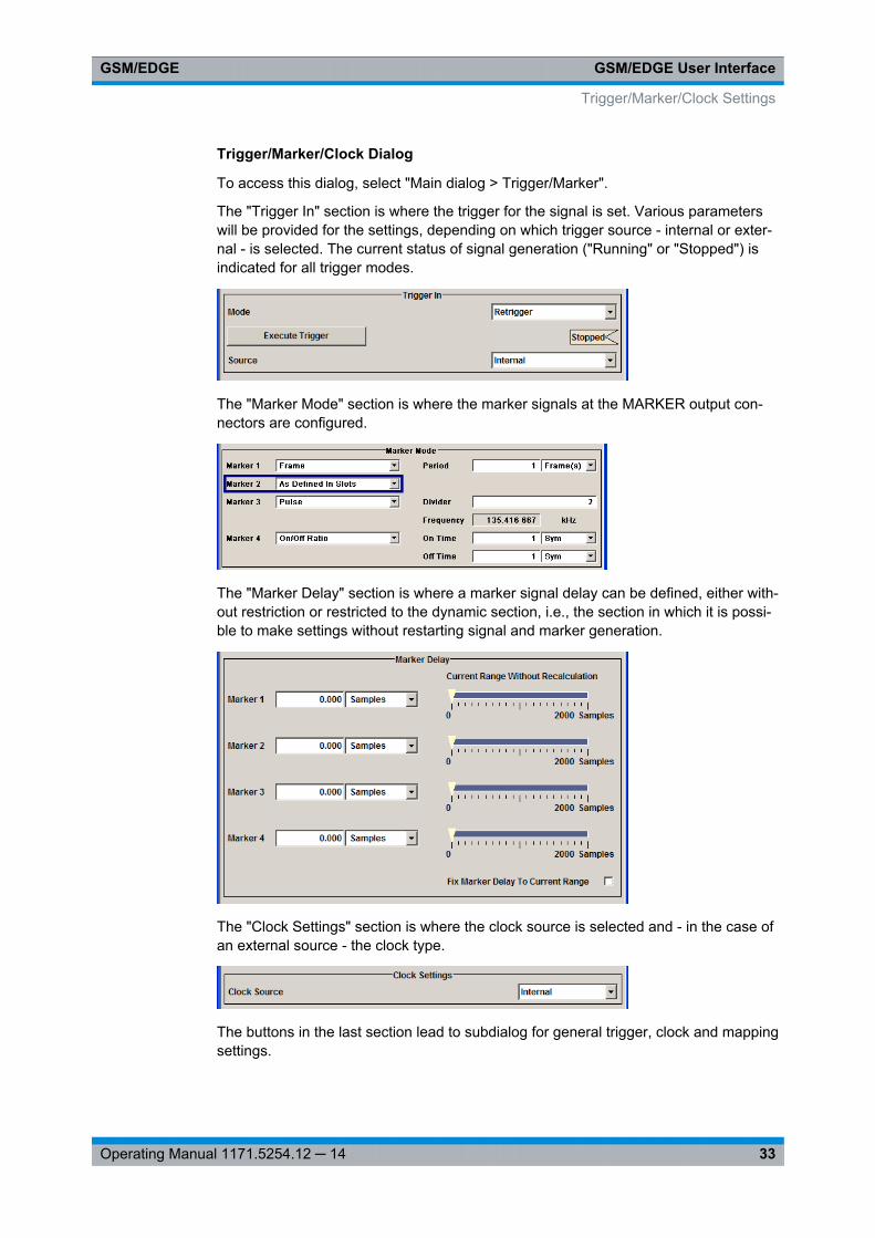
Trigger/Marker/Clock Dialog
To access this dialog, select "Main dialog > Trigger/Marker".
The "Trigger In" section is where the trigger for the signal is set. Various parameterswill be provided for the settings, depending on which trigger source - internal or exter-nal - is selected. The current status of signal generation ("Running" or "Stopped") isindicated for all trigger modes.
The "Marker Mode" section is where the marker signals at the MARKER output con-nectors are configured.
The "Marker Delay" section is where a marker signal delay can be defined, either with-out restriction or restricted to the dynamic section, i.e., the section in which it is possi-ble to make settings without restarting signal and marker generation.
The "Clock Settings" section is where the clock source is selected and - in the case ofan external source - the clock type.
The buttons in the last section lead to subdialog for general trigger, clock and mappingsettings.
Trigger/Marker/Clock Settings
GSM/EDGE User InterfaceGSM/EDGE
34Operating Manual 1171.5254.12 ─ 14
3.8.1 Trigger In
The trigger functions are available for R&S SMx and R&S AMU instruments only.
The "Trigger In" section is where the trigger for the signal is set. Various parameterswill be provided for the settings, depending on which trigger source - internal or exter-nal - is selected. The current status of signal generation ("Running" or "Stopped") isindicated for all trigger modes.
Trigger ModeSelects trigger mode, i.e. determines the effect of a trigger event on the signal genera-tion.
● "Auto"The signal is generated continuously.
● "Retrigger"The signal is generated continuously. A trigger event (internal or external) causes arestart.
● "Armed_Auto"The signal is generated only when a trigger event occurs. Then the signal is gener-ated continuously.An "Arm" stops the signal generation. A subsequent trigger event (internal with orexternal) causes a restart.
● "Armed_Retrigger"The signal is generated only when a trigger event occurs. Then the signal is gener-ated continuously. Every subsequent trigger event causes a restart.An "Arm" stops signal generation. A subsequent trigger event (internal with orexternal) causes a restart.
● "Single"The signal is generated only when a trigger event occurs. Then the signal is gener-ated once to the length specified at "Signal Duration".Every subsequent trigger event (internal or external) causes a restart.
Remote command: [: SOURce<hw>]: BB:GSM[: TRIGger]:SEQuence on page 84
Signal Duration UnitDefines the unit for the entry of the length of the signal sequence to be output in theSingle trigger mode. Available units are symbols or frames.
Remote command: [:SOURce<hw>]: BB:GSM: TRIGger:SLUNit on page 88
Trigger/Marker/Clock Settings
GSM/EDGE User InterfaceGSM/EDGE
35Operating Manual 1171.5254.12 ─ 14
Signal DurationEnters the length of the signal sequence to be output in the "Single" trigger mode.
Use this parameter to deliberately output part of the signal, an exact sequence of thesignal, or a defined number of repetitions of the signal.
Remote command: [:SOURce<hw>]: BB:GSM: TRIGger:SLENgth on page 87
Running - StoppedFor enabled modulation, displays the status of signal generation for all trigger modes.
● "Running"The signal is generated; a trigger was (internally or externally) initiated in triggeredmode.
● "Stopped"The signal is not generated and the instrument waits for a trigger event.
Remote command: [:SOURce<hw>]: BB:GSM:TRIGger: RMODe? on page 87
ArmFor trigger modes "Armed Auto" and "Armed Retrigger", stops the signal generationuntil subsequent trigger event occurs.
Remote command: [:SOURce<hw>]: BB:GSM: TRIGger:ARM: EXECute on page 85
Execute TriggerExecutes trigger manually.
You can execute the trigger manually only if you select an internal trigger source and atrigger mode other than "Auto".
Remote command: [:SOURce<hw>]: BB:GSM: TRIGger:EXECute on page 85
Trigger SourceSelects trigger source. This setting is effective when a trigger mode other than "Auto"has been selected.
● "Internal"The trigger event is executed by "Execute Trigger".
● "Internal (Baseband A/B)"(two-path instruments)The trigger event is the trigger signal from the second path
● "External (Trigger 1/2)"The trigger event is the active edge of an external trigger signal, supplied at theTRIGGER 1/2 connector.Use the "Global Trigger/Clock Settings" dialog to define the polarity, the triggerthreshold and the input impedance of the trigger signal.
Trigger/Marker/Clock Settings
GSM/EDGE User InterfaceGSM/EDGE
36Operating Manual 1171.5254.12 ─ 14
"ExternalClock"
Available if an external clock source is used. The trigger event is thesignal on the CLOCK connector.
Remote command: [:SOURce<hw>]: BB: GSM:TRIGger: SOURce on page 88
Sync. Output to External Trigger(enabled for Trigger Source External)
Enables/disables output of the signal synchronous to the external trigger event.
For R&S SMBV instruments:
For or two or more R&S SMBVs configured to work in a master-slave mode for syn-chronous signal generation, configure this parameter depending on the provided sys-tem trigger event and the properties of the output signal. See the table below for anoverview of the required settings.Table 3-1: Typical Applications
System Trigger Application "Sync. Output to External Trig-ger"
Common External Trigger eventfor the master and the slaveinstruments
All instruments are synchronousto the external trigger event
ON
All instruments are synchronousamong themselves but startingthe signal from first symbol ismore important than synchronicitywith external trigger event
OFF
Internal trigger signal of the mas-ter R&S SMBV for the slaveinstruments
All instruments are synchronousamong themselves
OFF
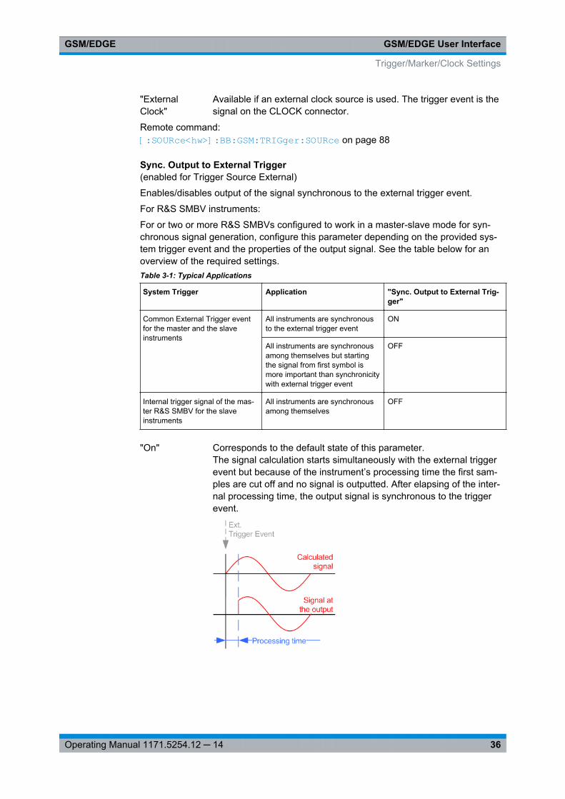
"On" Corresponds to the default state of this parameter.The signal calculation starts simultaneously with the external triggerevent but because of the instrument’s processing time the first sam-ples are cut off and no signal is outputted. After elapsing of the inter-nal processing time, the output signal is synchronous to the triggerevent.
Trigger/Marker/Clock Settings
GSM/EDGE User InterfaceGSM/EDGE
37Operating Manual 1171.5254.12 ─ 14
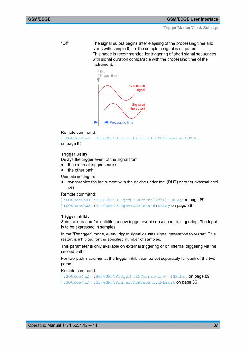
"Off" The signal output begins after elapsing of the processing time andstarts with sample 0, i.e. the complete signal is outputted.This mode is recommended for triggering of short signal sequenceswith signal duration comparable with the processing time of theinstrument.
Remote command: [:SOURce<hw>]: BB: GSM:TRIGger: EXTernal: SYNChronize: OUTPuton page 85
Trigger DelayDelays the trigger event of the signal from:● the external trigger source● the other pathUse this setting to:● synchronize the instrument with the device under test (DUT) or other external devi-
ces
Remote command: [:SOURce<hw>]: BB: GSM:TRIGger[: EXTernal<ch>]: DELay on page 89[: SOURce<hw>]: BB: GSM:TRIGger: OBASeband: DELay on page 86
Trigger InhibitSets the duration for inhibiting a new trigger event subsequent to triggering. The inputis to be expressed in samples.
In the "Retrigger" mode, every trigger signal causes signal generation to restart. Thisrestart is inhibited for the specified number of samples.
This parameter is only available on external triggering or on internal triggering via thesecond path.
For two-path instruments, the trigger inhibit can be set separately for each of the twopaths.
Remote command: [:SOURce<hw>]: BB:GSM:TRIGger[: EXTernal<ch>]: INHibit on page 89[:SOURce<hw>]: BB:GSM:TRIGger: OBASeband: INHibit on page 86
Trigger/Marker/Clock Settings
GSM/EDGE User InterfaceGSM/EDGE
38Operating Manual 1171.5254.12 ─ 14
3.8.2 Marker Mode
The marker output signal for synchronizing external instruments is configured in themarker settings section "Marker Mode".
The R&S SMBV supports only two markers.
Marker ModeSelects a marker signal for the associated "MARKER" output.
"As defined inSlots"
The marker defined for each slot separately in the burst editor isused. The name of the marker is displayed to the right of the selec-tion. Definition of the slot marker is described in chapter 3.10, "SlotMarker Definition", on page 55.
"Slot" A slot clock with the slot period specified under Period is generatedon the output connector. The marker signal is generated after everyspecified number of slots.It is important to be aware of the variation in the GSM/EDGE slotlength between 156 and 157 symbols. At a slot length of 156 sym-bols, a period of 1 symbol and a symbol rate of 270.833 ksymb/s theclock is 0.577 ms, and at 157 symbols it is 0.580 ms
"Restart" A marker signal is generated at the start of each ARB sequence.
"Frame " A frame clock with the frame period specified under Period is gener-ated on the output connector. The marker signal is generated afterevery specified number of frames.A GSM/EDGE frame has 1250 symbols. At a symbol rate of 270.833ksymb/s and a period of 1 the clock is 4.615 ms.
"Pulse" A regular marker signal is generated. The pulse frequency is definedby entering a divider. The frequency is derived by dividing the samplerate by the divider. The input box for the divider opens when "Pulse"is selected, and the resulting pulse frequency is displayed below it.The maximum pulse frequency is half the symbol rate.
Remote command: [:SOURce<hw>]: BB: GSM:TRIGger: OUTPut<ch>: PULSe:DIVider on page 95[:SOURce<hw>]: BB: GSM:TRIGger: OUTPut<ch>: PULSe[: FREQuency]? on page 95
"Pattern " A marker signal that is defined by a bit pattern is generated. The pat-tern has a maximum length of 64 bits and is defined in an input fieldwhich opens when pattern is selected.
Remote command: [:SOURce<hw>]: BB: GSM:TRIGger: OUTPut<ch>: PATTern on page 94
Trigger/Marker/Clock Settings
GSM/EDGE User InterfaceGSM/EDGE
39Operating Manual 1171.5254.12 ─ 14
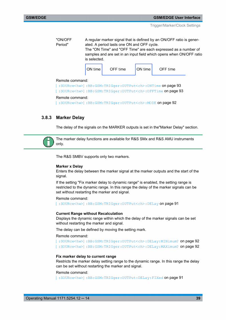
"ON/OFFPeriod"
A regular marker signal that is defined by an ON/OFF ratio is gener-ated. A period lasts one ON and OFF cycle.The "ON Time" and "OFF Time" are each expressed as a number ofsamples and are set in an input field which opens when ON/OFF ratiois selected.
Remote command: [:SOURce<hw>]: BB: GSM:TRIGger: OUTPut<ch>: ONTime on page 93[:SOURce<hw>]: BB: GSM:TRIGger: OUTPut<ch>: OFFTime on page 93
Remote command: [:SOURce<hw>]: BB: GSM:TRIGger: OUTPut<ch>: MODE on page 92
3.8.3 Marker Delay
The delay of the signals on the MARKER outputs is set in the"Marker Delay" section.
The marker delay functions are available for R&S SMx and R&S AMU instrumentsonly.
The R&S SMBV supports only two markers.
Marker x DelayEnters the delay between the marker signal at the marker outputs and the start of thesignal.
If the setting "Fix marker delay to dynamic range" is enabled, the setting range isrestricted to the dynamic range. In this range the delay of the marker signals can beset without restarting the marker and signal.
Remote command: [: SOURce<hw>]: BB:GSM:TRIGger: OUTPut<ch>: DELay on page 91
Current Range without RecalculationDisplays the dynamic range within which the delay of the marker signals can be setwithout restarting the marker and signal.
The delay can be defined by moving the setting mark.
Remote command: [:SOURce<hw>]: BB:GSM:TRIGger: OUTPut<ch>: DELay: MINimum? on page 92[:SOURce<hw>]: BB:GSM:TRIGger: OUTPut<ch>: DELay: MAXimum? on page 92
Fix marker delay to current rangeRestricts the marker delay setting range to the dynamic range. In this range the delaycan be set without restarting the marker and signal.
Remote command: [:SOURce<hw>]: BB:GSM: TRIGger: OUTPut:DELay: FIXed on page 91
Trigger/Marker/Clock Settings
GSM/EDGE User InterfaceGSM/EDGE
40Operating Manual 1171.5254.12 ─ 14
3.8.4 Clock Settings
The Clock Settings is used to set the clock source and a delay if required.
The clock functions are available for R&S SMx and R&S AMU instruments only.
Sync. Mode(for R&S SMBV only)
Selects the synchronization mode.
This parameter is used to enable generation of very precise synchronous signal of sev-eral connected R&S SMBVs.
Note: If several instruments are connected, the connecting cables from the masterinstrument to the slave one and between each two consecutive slave instruments musthave the same length and type.Avoid unnecessary cable length and branching points.
"None" The instrument is working in stand-alone mode.
"Sync. Master" The instrument provides all connected instrument with its synchroni-sation (including the trigger signal) and reference clock signal.
"Sync. Slave" The instrument receives the synchronisation and reference clock sig-nal from another instrument working in a master mode.
Remote command: [:SOURce<hw>]: BB: GSM:CLOCk: SYNChronization: MODE on page 83
Set Synchronization Settings(for R&S SMBV only)
Performs automatically adjustment of the instrument's settings required for the syn-chronization mode, selected with the parameter "Synchronization Mode".
Remote command: [:SOURce<hw>]: BB: GSM:CLOCk: SYNChronization: EXECute on page 82
Clock SourceSelects the clock source.
"Internal" The internal clock reference is used to generate the symbol clock.
Trigger/Marker/Clock Settings
GSM/EDGE User InterfaceGSM/EDGE
41Operating Manual 1171.5254.12 ─ 14
"External" The external clock reference is fed in as the symbol clock or multiplethereof via the CLOCK connector.The symbol rate must be correctly set to an accuracy of +/-2 % (seedata sheet).The polarity of the clock input can be changed with the aid of "GlobalTrigger/Clock Settings".In the case of two-path instruments this selection applies to path A.
Remote command: [:SOURce<hw>]: BB: GSM:CLOCk: SOURce on page 82
Clock ModeEnters the type of externally supplied clock.
"Symbol" A symbol clock is supplied via the CLOCK connector.
"Bit" A bit clock is supplied via the CLOCK connector; the symbol clock isderived internally from this.
"Multiple Sym-bol"
A multiple of the symbol clock is supplied via the CLOCK connector;the symbol clock is derived internally from this.
"FractionalSymbol"
A fraction of the symbol clock is supplied via the CLOCK connector;the symbol clock is derived internally from this.
Note: This selection is only available for external clock signals with aclock rate of at least 200 Hz.
Remote command: [:SOURce<hw>]: BB: GSM:CLOCk: MODE on page 80
Clock MultiplierEnters the multiplication factor for clock type "Multiple".
Remote command: [:SOURce<hw>]: BB:GSM: CLOCk:MULTiplier on page 81
Symbol Clock DividerEnters the divider for clock type "Fraction".
Remote command: [:SOURce<hw>]: BB: GSM:CLOCk: DIVider on page 81
Measured External ClockProvided for permanent monitoring of the enabled and externally supplied clock signal.
Remote command: CLOCk:INPut:FREQuency?
3.8.5 Global Settings
The buttons in this section lead to dialogs for general trigger, clock and mapping set-tings.
These settings are available for R&S SMx and R&S AMU instruments only.
Trigger/Marker/Clock Settings
GSM/EDGE User InterfaceGSM/EDGE
42Operating Manual 1171.5254.12 ─ 14
Global Trigger/Clock SettingsCalls the "Global Trigger/Clock/Input Settings" dialog.
This dialog is used among other things for setting the trigger threshold, the input impe-dance and the polarity of the clock and trigger inputs.
In the case of two-path instruments, these settings are valid for both paths.
The parameters in this dialog affect all digital modulations and standards, and aredescribed in chapter "Global Trigger/Clock/Input Settings" in the Operating Manual.
User Marker / AUX I/O SettingsCalls the "User Marker AUX I/O Settings" dialog, used to map the connector on therear of the instruments.
See also "User Marker / AUX I/O Settings" in the Operating Manual.
3.9 Burst Editor
To call the burst editor, select a slot from the graphical display in the GSM/EDGE dia-log.
At the top of the "Common " dialog the structure of the current burst type for theselected slot is displayed. Individual fields of the burst are color-coded:
Field Color
Data, Fixed, Mixed, Stealing white
Training Sequences: TSC, ETSC, SYNC yellow
Tail, extended Tail green
Guard, extended Guard blue
Burst Editor
GSM/EDGE User InterfaceGSM/EDGE
43Operating Manual 1171.5254.12 ─ 14
The rest of the dialog displays the data contained in fields predefined by the standardfor the current burst type. Data fields with variable content can be edited. Values infields with permanently predefined content are not highlighted in any way.
The provided settings depend on the selcted "Burst Type".
The following sections list all possible settings and displays for the various burst types.If a setting applies only to a particular burst type, this is mentioned for the parameterconcerned.
Burst TypeSelects burst type.
The available burst types depend on the selected "Symbol Rate Mode".
Note: "Higher Symbol Rate Mode", AQPSK modulations and higher order modulationschemes (16QAM and 32QAM) are available for instruments equipped with optionR&S SMx/AMU only.
"Normal (GMSK/Full Rate)"(Normal Symbol Rate)The useful data is transmitted in the Normal Burst (NB).A normal burst carries 2*58 = 116 encrypted bits.
Burst Editor
GSM/EDGE User InterfaceGSM/EDGE
44Operating Manual 1171.5254.12 ─ 14
"Normal (GMSK/Half Rate)"(Normal Symbol Rate)The useful data is transmitted in the Normal burst.Half rate user 1 is transmitted in all the frames with an even index(frames 0, 2, 4, etc.) and half rate user 2 is transmitted in the frameswith an odd index (frames 1, 3, etc.)See alsochapter 3.3, "Mode Framed (single)", on page 18 .
"Normal (AQPSK/Full Rate - Full Rate)"The data of pair of users is multiplexed on the two VAMOS subchan-nels of a single physical radio resource.See also chapter 2.1, "VAMOS (Voice services over Adaptive Multi-user channels on One Slot)", on page 8.
"Normal (AQPSK/Full Rate - Half Rate)"Three users are using the same radio resource, one full rate VAMOSuser on the subchannel 1 and two half rate VAMOS users on the sub-channel 2.
Burst Editor
GSM/EDGE User InterfaceGSM/EDGE
45Operating Manual 1171.5254.12 ─ 14
"Normal (AQPSK/Half Rate - Half Rate)"A single time slot is shared by four users: two VAMOS subchannels,each used by two half rate users.
"Normal(8PSK/EDGE)"
(Normal Symbol Rate)The higher bit clock associated with EDGE achieves correspondinglyhigher data transfer rates.If a frame contains an active EDGE burst, the higher bit clock (3 xsymbol clock) is always output on the clock outputs. If the EDGEburst is removed from the frame, the lower bit clock (=symbol clock)is automatically output again.An EDGE burst carries 2x(3*58) = 348 encrypted bits.
"Normal (16QAM)"(Normal Symbol Rate)Selects a normal burst with 16QAM modulation scheme (4 bits persymbol).A normal 16QAM burst carries 2x(4*58) = 464 encrypted bits.
"Normal(32QAM)"
(Normal Symbol Rate)Selects a normal burst with 32QAM modulation scheme (5 bits persymbol).A normal 32QAM burst carries 2x(5*58) = 580 encrypted bits.
Burst Editor
GSM/EDGE User InterfaceGSM/EDGE
46Operating Manual 1171.5254.12 ─ 14
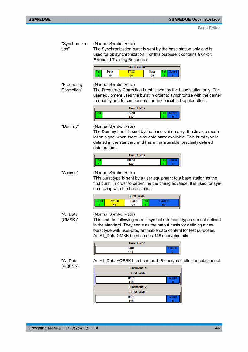
"Synchroniza-tion"
(Normal Symbol Rate)The Synchronization burst is sent by the base station only and isused for bit synchronization. For this purpose it contains a 64-bitExtended Training Sequence.
"FrequencyCorrection"
(Normal Symbol Rate)The Frequency Correction burst is sent by the base station only. Theuser equipment uses the burst in order to synchronize with the carrierfrequency and to compensate for any possible Doppler effect.
"Dummy" (Normal Symbol Rate)The Dummy burst is sent by the base station only. It acts as a modu-lation signal when there is no data burst available. This burst type isdefined in the standard and has an unalterable, precisely defineddata pattern.
"Access" (Normal Symbol Rate)This burst type is sent by a user equipment to a base station as thefirst burst, in order to determine the timing advance. It is used for syn-chronizing with the base station.
"All Data(GMSK)"
(Normal Symbol Rate)This and the following normal symbol rate burst types are not definedin the standard. They serve as the output basis for defining a newburst type with user-programmable data content for test purposes.An All_Data GMSK burst carries 148 encrypted bits.
"All Data(AQPSK)"
An All_Data AQPSK burst carries 148 encrypted bits per subchannel.
Burst Editor
GSM/EDGE User InterfaceGSM/EDGE
47Operating Manual 1171.5254.12 ─ 14
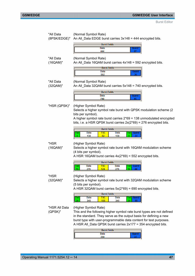
"All Data(8PSK/EDGE)"
(Normal Symbol Rate)An All_Data EDGE burst carries 3x148 = 444 encrypted bits.
"All Data(16QAM)"
(Normal Symbol Rate)An All_Data 16QAM burst carries 4x148 = 592 encrypted bits.
"All Data(32QAM)"
(Normal Symbol Rate)An All_Data 32QAM burst carries 5x148 = 740 encrypted bits.
"HSR (QPSK)" (Higher Symbol Rate)Selects a higher symbol rate burst with QPSK modulation scheme (2bits per symbol).A higher symbol rate burst carries 2*69 = 138 unmodulated encryptedbits, i.e. a HSR QPSK burst carries 2x(2*69) = 276 encrypted bits.
"HSR(16QAM)"
(Higher Symbol Rate)Selects a higher symbol rate burst with 16QAM modulation scheme(4 bits per symbol).A HSR 16QAM burst carries 4x(2*69) = 552 encrypted bits.
"HSR(32QAM)"
(Higher Symbol Rate)Selects a higher symbol rate burst with 32QAM modulation scheme(5 bits per symbol).A HSR 32QAM burst carries 5x(2*69) = 690 encrypted bits.
"HSR All Data(QPSK)"
(Higher Symbol Rate)This and the following higher symbol rate burst types are not definedin the standard. They serve as the output basis for defining a newburst type with user-programmable data content for test purposes.A HSR All_Data QPSK burst carries 2x177 = 354 encrypted bits.
Burst Editor
GSM/EDGE User InterfaceGSM/EDGE
48Operating Manual 1171.5254.12 ─ 14
"HSR All Data(16QAM)"
(Higher Symbol Rate)A HSR All_Data 16QAM burst carries 4x177 = 708 encrypted bits.
"HSR All Data(32QAM)"
(Higher Symbol Rate)A HSR All_Data 32QAM burst carries 5x177 = 885 encrypted bits.
Remote command: [:SOURce<hw>]: BB: GSM[:FRAMe<di>]: SLOT<st0>: TYPE on page 99
Save-Recall SlotsAccesses the "Save/Recall Slot" dialog with standard "File Select" and file manage-ment functions, see chapter 3.5, "Save Recall Frame/Slots", on page 21.
Remote command: n.a.
User xWhen burst type "Normal (Half Rate)" is selected the users can be set separately indialog sections User 1 and User 2.
Remote command: n.a.
SCPIRSelects the SCPIR.
The value of SCPIR affects the shape of the AQPSK constellation, see figure 2-2. Foran SCPIR of 0 dB the constellation is square (as in "normal" QPSK), while for othervalues of SCPIR the constellation becomes rectangular.
Use the Modulation/Filter dialog to define eight different values for SCPIR. You mayselect from the values displayed.
Remote command: [:SOURce<hw>]: BB:GSM[: FRAMe<di>]: SLOT<st0>[: SUBChannel<us>][: USER<ch>]: SCPIRatio on page 100
Slot LevelSets the level for the selected slot.
"Off" Attenuation is maximum. The slot is inactive.
"Attenuated" Level is reduced by the level attenuation set in "Slot Attenuation".
"Full" The level corresponds to the level indicated in the display.
Remote command: [:SOURce<hw>]: BB: GSM[:FRAMe<di>]: SLOT<st0>[: SUBChannel<us>][: USER<ch>]: LEVel on page 99
Burst Editor
GSM/EDGE User InterfaceGSM/EDGE
49Operating Manual 1171.5254.12 ─ 14
Slot AttenuationSelects the level attenuation for the "Slot Level Attenuated" setting.
Use the Power Ramping/Slot Attenuation dialog to define seven different values forlevel attenuation. You may select from the values displayed.
Remote command: [:SOURce<hw>]: BB:GSM[: FRAMe<di>]: SLOT<st0>[: SUBChannel<us>][: USER<ch>]:ATTenuation on page 100
Filter(for Higher Symbol Rate slots and instruments equipped with R&S SMx/AMU-K41only)
Selects whether a Narrow Pulse Shape or a Wide Pulse Shape filter should be use forthe selected burst type and modulation.
Remote command: [:SOURce<hw>]: BB:GSM[: FRAMe<di>]: SLOT<st0>[: SUBChannel<us>][: USER<ch>]: FILTer:TYPE on page 101
Multislot ConfigurationEnables the previously set multislot mode.
Since multislot involves connecting multiple slots to a single user channel, this configu-ration is possible for Normal (Full Rate) bursts, Normal (8PSK/EDGE) burst and EDGEEvolution bursts.
A number of multislot groups can be defined within a frame. These are highlightedwhen the frame structure is displayed in the main dialog (see chapter 3.3, "ModeFramed (single)", on page 18).
The first slot in a multislot group is the master slot. This determines the parameters ofall the slots in the group. All the slots in a multislot group therefore have identicalparameters.
The multislot settings are valid for all the slots in the frames of a multiframe configura-tion. If slots 1 and 2 are connected, for example, both these slots are connected in allthe frames of the multiframe signal.
Remote command: [:SOURce<hw>]: BB: GSM[:FRAMe<di>]: MULTislot<st0>: STATe on page 104
Number of SlotsDefines the number of consecutive slots that will be linked to a multislot.
Burst Editor
GSM/EDGE User InterfaceGSM/EDGE
50Operating Manual 1171.5254.12 ─ 14
The multislot always starts with the current slot. The value range therefore depends onthe current slot index. A maximum of 8 slots (slot 0 to slot 7) can be combined: 1 ... (8 -current index).
Remote command: [:SOURce<hw>]: BB:GSM[: FRAMe<di>]: MULTislot<st0>: COUNt on page 101
VAMOS Offset Jitter(enabled in R&S SMU/AMU)
Enables/disables the simulation of a timing jitter for GMSK bursts.
The test specification 3GPP TS 45.005, Annex Q5 defines that for uplink tests inVAMOS mode, both interference and sensitivity limited cases are specified for VAMOSsubchannel 1 that is offset in time and frequency with respect to VAMOS subchannel2. If this parameter is activated, the instrument applys a timing offset (jitter) with ran-domly selected value in the range of -1, 0 or 1 symbol period. The timing offsetchanges between the bursts; within a burst, the instrument keeps the time and fre-quency offsets constant.
In the R&S SMU, the required frequency jitter can be simulated by means of the "ListMode" function of the instrument.
Remote command: [:SOURce<hw>]: BB:GSM[: FRAMe<di>]: SLOT<st0>: VOJitter on page 102
Burst FieldsComprises settings for configuring of the individual burst fields.
The available settings depends on the selected Burst Type.
Extended Tail Bits ← Burst FieldsDisplays the data content in the "ETail" data field of the Access burst.
Extended Tail Bits fields are 8 bits long and permanently set at 0011 1010.
Remote command: n.a.
Tail Bits ← Burst FieldsDisplays the data content in the "Tail" data field.
The content depends on the "Burst Type":● Normal (GMSK...), Normal (AQPSK...), Synchronization, Frequency Correction,
Dummy and Access"Tail Bit" field is 3 Bits long and permanently set at 000.
● Normal(8PSK/EDGE)"Tail Bit" field is 9 Bits long and permanently set at 1 1111 1111.
● Normal (16QAM)"Tail Bit" field is 12 Bits long and permanently set at 0001 0110 0110.
● Normal (32QAM)"Tail Bit" field is 15 Bits long and permanently set at 111 1001 1100 1110.
Remote command: n.a.
Burst Editor
GSM/EDGE User InterfaceGSM/EDGE
51Operating Manual 1171.5254.12 ─ 14
Data for Data Field of Slot ← Burst FieldsSelects a data source for the DATA field.
If a burst contains multiple DATA fields, these are treated as a continuous field, and forinstance a pseudo-random sequence is continued without interruption from one DATAfield to the next.
The following standard data sources are available:● "All 0, All 1"
An internally generated sequence containing 0 data or 1 data.● "PNxx"
An internally generated pseudo-random noise sequence.● "Pattern"
An internally generated sequence according to a bit pattern.Use the "Pattern" box to define the bit pattern.
● "Data List/Select DList"A binary data from a data list, internally or externally generated.Select "Select DList" to access the standard "Select List" dialog.– Select the "Select Data List > navigate to the list file *.dm_iqd > Select" to
select an existing data list.– Use the "New" and "Edit" functions to create internally new data list or to edit
an existing one.– Use the standard "File Manager" function to transfer external data lists to the
instrument.See also "Main Dialog > Data List Management".
Remote command: [:SOURce<hw>]: BB: GSM[: FRAMe<di>]: SLOT<st0>[: SUBChannel<us>][: USER<ch>][: SOURce]: DATA on page 102[:SOURce<hw>]: BB: GSM[:FRAMe<di>]: SLOT<st0>[: SUBChannel<us>][: USER<ch>][: SOURce]: DATA:PATTern on page 103[:SOURce<hw>]: BB: GSM[:FRAMe<di>]: SLOT<st0>[: SUBChannel<us>][: USER<ch>][: SOURce]: DATA:DLISt: CATalog? on page 103[:SOURce<hw>]: BB: GSM[:FRAMe<di>]: SLOT<st0>[: SUBChannel<us>][: USER<ch>][: SOURce]: DATA:DLISt on page 103
Use Stealing Flag ← Burst FieldsSets the Use Stealing Flag feature. The setting applies to both S fields. If not used, theflag stealing bit is allocated to the data field concerned, which then becomes 58 databits long instead of 57.
Remote command: [:SOURce<hw>]: BB:GSM[: FRAMe<di>]: SLOT<st0>[: SUBChannel<us>][: USER<ch>]: SFLag:USE on page 105
Stealing Flag ← Burst FieldsSets a value for the Stealing Flag feature. The setting applies to both S fields.
Remote command: [:SOURce<hw>]: BB: GSM[:FRAMe<di>]: SLOT<st0>[: SUBChannel<us>][: USER<ch>]: SFLag on page 104
Burst Editor
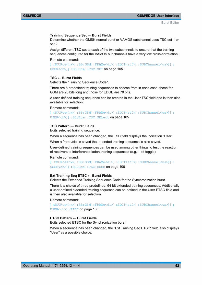
GSM/EDGE User InterfaceGSM/EDGE
52Operating Manual 1171.5254.12 ─ 14
Training Sequence Set ← Burst FieldsDetermine whether the GMSK normal burst or VAMOS subchannel uses TSC set 1 orset 2.
Assign different TSC set to each of the two subcahnnels to ensure that the trainingsequences configured for the VAMOS subchannels have a very low cross-correlation.
Remote command: [:SOURce<hw>]: BB:GSM[: FRAMe<di>]: SLOT<st0>[: SUBChannel<us>][: USER<ch>][: SOURce]: TSC:SET on page 105
TSC ← Burst FieldsSelects the "Training Sequence Code".
There are 8 predefined training sequences to choose from in each case; those forGSM are 26 bits long and those for EDGE are 78 bits.
A user-defined training sequence can be created in the User TSC field and is then alsoavailable for selection.
Remote command: [:SOURce<hw>]: BB:GSM[:FRAMe<di>]: SLOT<st0>[: SUBChannel<us>][: USER<ch>][: SOURce]: TSC: SELect on page 105
TSC Pattern ← Burst FieldsEdits selected training sequence.
When a sequence has been changed, the TSC field displays the indication "User".
When a frame/slot is saved the amended training sequence is also saved.
User-defined training sequences can be used among other things to test the reactionof receivers to interference-laden training sequences (e.g. 1 bit toggle).
Remote command: [: SOURce<hw>]: BB:GSM[:FRAMe<di>]: SLOT<st0>[: SUBChannel<us>][: USER<ch>][: SOURce]: TSC: USER on page 106
Ext Training Seq ETSC ← Burst FieldsSelects the Extended Training Sequence Code for the Synchronization burst.
There is a choice of three predefined, 64-bit extended training sequences. Additionallya user-defined extended training sequence can be defined in the User ETSC field andis then also available for selection.
Remote command: [:SOURce<hw>]: BB:GSM[: FRAMe<di>]: SLOT<st0>[: SUBChannel<us>][: USER<ch>]: ETSC on page 106
ETSC Pattern ← Burst FieldsEdits selected ETSC for the Synchronization burst.
When a sequence has been changed, the "Ext Training Seq ETSC" field also displays"User" as a possible choice.
Burst Editor
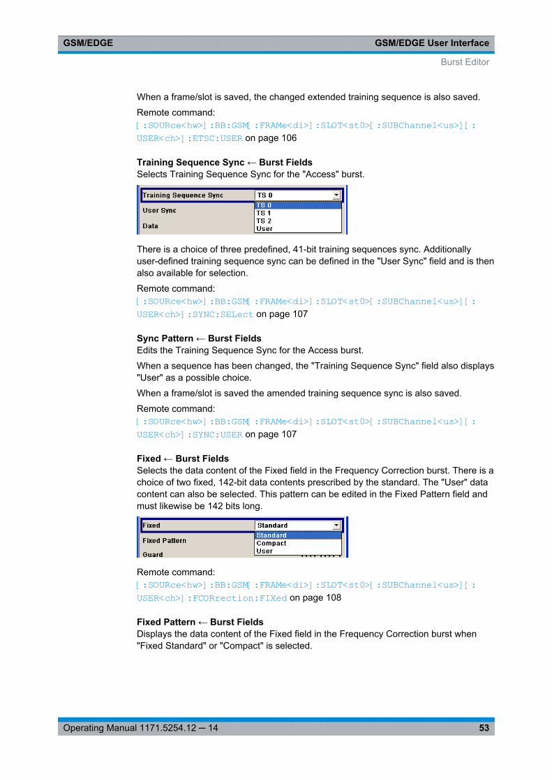
GSM/EDGE User InterfaceGSM/EDGE
53Operating Manual 1171.5254.12 ─ 14
When a frame/slot is saved, the changed extended training sequence is also saved.
Remote command: [:SOURce<hw>]: BB:GSM[: FRAMe<di>]: SLOT<st0>[: SUBChannel<us>][: USER<ch>]: ETSC:USER on page 106
Training Sequence Sync ← Burst FieldsSelects Training Sequence Sync for the "Access" burst.
There is a choice of three predefined, 41-bit training sequences sync. Additionallyuser-defined training sequence sync can be defined in the "User Sync" field and is thenalso available for selection.
Remote command: [:SOURce<hw>]: BB: GSM[:FRAMe<di>]: SLOT<st0>[: SUBChannel<us>][: USER<ch>]: SYNC:SELect on page 107
Sync Pattern ← Burst FieldsEdits the Training Sequence Sync for the Access burst.
When a sequence has been changed, the "Training Sequence Sync" field also displays"User" as a possible choice.
When a frame/slot is saved the amended training sequence sync is also saved.
Remote command: [:SOURce<hw>]: BB: GSM[:FRAMe<di>]: SLOT<st0>[: SUBChannel<us>][: USER<ch>]: SYNC: USER on page 107
Fixed ← Burst FieldsSelects the data content of the Fixed field in the Frequency Correction burst. There is achoice of two fixed, 142-bit data contents prescribed by the standard. The "User" datacontent can also be selected. This pattern can be edited in the Fixed Pattern field andmust likewise be 142 bits long.
Remote command: [:SOURce<hw>]: BB: GSM[:FRAMe<di>]: SLOT<st0>[: SUBChannel<us>][: USER<ch>]: FCORrection: FIXed on page 108
Fixed Pattern ← Burst FieldsDisplays the data content of the Fixed field in the Frequency Correction burst when"Fixed Standard" or "Compact" is selected.
Burst Editor
GSM/EDGE User InterfaceGSM/EDGE
54Operating Manual 1171.5254.12 ─ 14
Enter the data content of the Fixed field in the Frequency Correction burst when "FixedUser" is selected. The pattern is 142 bits long.
Remote command: [:SOURce<hw>]: BB:GSM[: FRAMe<di>]: SLOT<st0>[: SUBChannel<us>][: USER<ch>]: FCORrection: FIXed:PATTern on page 108
Mixed ← Burst FieldsDisplays the data content of the Mixed field in the Dummy burst. It contains a fixed,142-bit data content prescribed by the standard.
Remote command: [:SOURce<hw>]: BB: GSM[:FRAMe<di>]: SLOT<st0>[: SUBChannel<us>][: USER<ch>]: DUMMy: MIXed: PATTern? on page 108
Guard ← Burst FieldsDisplays the data content of the Guard field in binary notation.
In order for a frame to contain exactly 1250 bits for normal burst and 1500 for highersymbol rate burst as prescribed in the GSM standard, the length of the Guard fields isdifferent for different slots (see table).
Normal Symbol Rate
Slot # 0, 4 1 .. 3, 5 .. 7
Guard Length 9 symbol periods 8 symbol periods
Higher Symbol Rate
Slot # 0, 2, 4, 6 1, 3, 5, 7
Guard Length 11 symbol periods 10 symbol periods
If the field Ignore "1/4 symbol (slot length 156 symbols) / Ignore ½ symbol (slot length187 symbols)" is enabled, all slots are 156 respectively 187 symbols long. The extra1/4 resp. 1/2 symbols is omitted. The guard field for the burst always has the samelength regardless of the slot index.
For normal burst, a frame is therefore 1248 symbols long instead of 1250.
Respectively, the length of the frame in a higher symbol rate burst is then 1496 sym-bols long instead of 1500 symbols.
Remote command: n.a.
Extended Guard ← Burst FieldsDisplays the data content of the Extended Guard field in the Access burst.
In order for a frame to contain exactly 1250 symbols as prescribed in the GSM stand-ard, the length of the extended Guard fields is different for different slots:
The field length is 68 bits in slots 1, 2, 3, 5, 6, 7 and 69 bits in slots 0 and 4.
Burst Editor
GSM/EDGE User InterfaceGSM/EDGE
55Operating Manual 1171.5254.12 ─ 14
If the field "Ignore 1/4 symbol (slot length 156 symbols)" is enabled, all slots are 156symbols long. The extra 1/4 symbol is omitted. The extended guard field for the burstalways has the same length regardless of the slot index. A frame is therefore 1248symbols long in place of 1250.
Remote command: n.a.
Slot Marker DefinitionAccess the dialog for defining the marker signal at slot level. This dialog is described inthechapter 3.10, "Slot Marker Definition", on page 55 .
Remote command: n.a.
3.10 Slot Marker Definition
To call the "Control List Editor" for defining the marker signal at slot level, use the "SlotMarker Definition" button in the burst editor of the GSM/EDGE dialog.
The marker signals thus defined will only become effective if the "As defined in slot"marker type in the "Trigger/Marker/Clock dialog" is selected.
The structure of the selected slot (in the example, synchronization burst) is displayed inthe dialog header. The individual fields of the burst are color-coded.
The available marker signals are also color-coded. In the left "Configure Control Sig-nal" section, each individual signal is assigned a color; a check in the check box showsthe marker for which the "As defined in slot" marker type has been selected.
In the next section, "Select Ramp to Edit", the signal characteristics are graphically dis-played.
The ramps can be assigned the exact bit position in the signal by means of● The schematic display of the slot above the section.● The bit scale below the marker/control signal characteristic.● The display of the current cursor position in the "Cursor" dialog section if the cursor
marks the ramp. The field at the selected position in the slot is displayed on theside. The bit position of the cursor within this field is displayed below
The ramps can be set either graphically in the "Select Ramp to Edit" section or in thetable of the "Positions Marker x" section. To make the setting easy, a selection of pre-set ramp characteristics is offered in the "Preset Ramp Marker x" section.
Slot Marker Definition
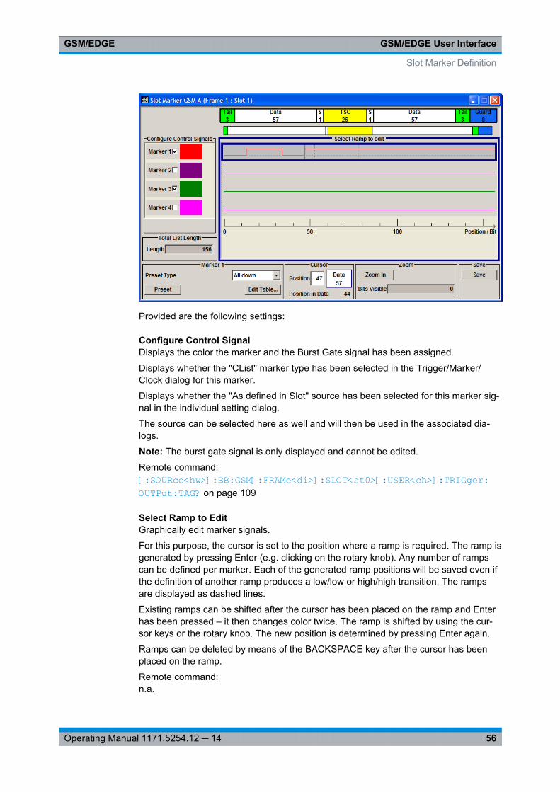
GSM/EDGE User InterfaceGSM/EDGE
56Operating Manual 1171.5254.12 ─ 14
Provided are the following settings:
Configure Control SignalDisplays the color the marker and the Burst Gate signal has been assigned.
Displays whether the "CList" marker type has been selected in the Trigger/Marker/Clock dialog for this marker.
Displays whether the "As defined in Slot" source has been selected for this marker sig-nal in the individual setting dialog.
The source can be selected here as well and will then be used in the associated dia-logs.
Note: The burst gate signal is only displayed and cannot be edited.
Remote command: [: SOURce<hw>]: BB:GSM[: FRAMe<di>]: SLOT<st0>[: USER<ch>]: TRIGger: OUTPut: TAG? on page 109
Select Ramp to EditGraphically edit marker signals.
For this purpose, the cursor is set to the position where a ramp is required. The ramp isgenerated by pressing Enter (e.g. clicking on the rotary knob). Any number of rampscan be defined per marker. Each of the generated ramp positions will be saved even ifthe definition of another ramp produces a low/low or high/high transition. The rampsare displayed as dashed lines.
Existing ramps can be shifted after the cursor has been placed on the ramp and Enterhas been pressed – it then changes color twice. The ramp is shifted by using the cur-sor keys or the rotary knob. The new position is determined by pressing Enter again.
Ramps can be deleted by means of the BACKSPACE key after the cursor has beenplaced on the ramp.
Remote command: n.a.
Slot Marker Definition
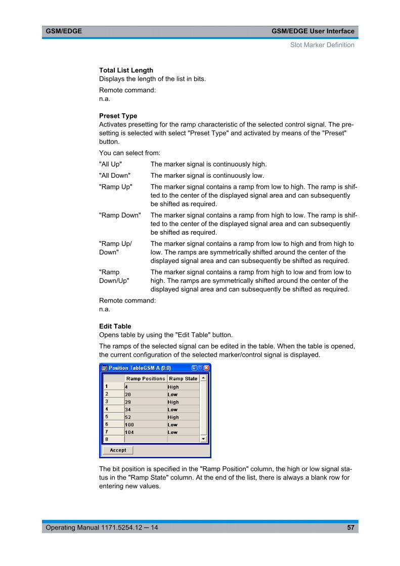
GSM/EDGE User InterfaceGSM/EDGE
57Operating Manual 1171.5254.12 ─ 14
Total List LengthDisplays the length of the list in bits.
Remote command: n.a.
Preset TypeActivates presetting for the ramp characteristic of the selected control signal. The pre-setting is selected with select "Preset Type" and activated by means of the "Preset"button.
You can select from:
"All Up" The marker signal is continuously high.
"All Down" The marker signal is continuously low.
"Ramp Up" The marker signal contains a ramp from low to high. The ramp is shif-ted to the center of the displayed signal area and can subsequentlybe shifted as required.
"Ramp Down" The marker signal contains a ramp from high to low. The ramp is shif-ted to the center of the displayed signal area and can subsequentlybe shifted as required.
"Ramp Up/Down"
The marker signal contains a ramp from low to high and from high tolow. The ramps are symmetrically shifted around the center of thedisplayed signal area and can subsequently be shifted as required.
"RampDown/Up"
The marker signal contains a ramp from high to low and from low tohigh. The ramps are symmetrically shifted around the center of thedisplayed signal area and can subsequently be shifted as required.
Remote command: n.a.
Edit TableOpens table by using the "Edit Table" button.
The ramps of the selected signal can be edited in the table. When the table is opened,the current configuration of the selected marker/control signal is displayed.
The bit position is specified in the "Ramp Position" column, the high or low signal sta-tus in the "Ramp State" column. At the end of the list, there is always a blank row forentering new values.
Slot Marker Definition
GSM/EDGE User InterfaceGSM/EDGE
58Operating Manual 1171.5254.12 ─ 14
The changes are accepted in the graphic display after pressing the "Accept" button.
Remote command: n.a.
Cursor PositionEnters the cursor position.
In the graphic display, the cursor is positioned according to the entry.
Vice versa, graphically shifting the cursor will change the displayed value.
The field at the selected position in the slot is displayed on the side. The bit position ofthe cursor within this field is displayed below.
Remote command: n.a.
Zoom/VisibleZooms the displayed area of the control list. The designation of the button changesfrom "Zoom in" to "Zoom out".
With long control lists, the displayed area can be zoomed around the current "CursorPosition".
Parameter "Visible/Bits Visible" determines the number of symbols/bits to be displayed.
Ramps outside the displayed area are not lost by zooming.
Remote command: n.a.
SaveSaves the settings made in the "Slot Marker" dialog into a file with file name formatGsmMarkSlotDefP<x>F<y>S<z>U<w>.dm_iqc, where:● x the path number,● y is the Frame number,● z is the Slot number and● w is the User number.
Remote command: n.a.
Slot Marker Definition
Remote-Control CommandsGSM/EDGE
59Operating Manual 1171.5254.12 ─ 14
4 Remote-Control CommandsThe following commands are required to perform signal generation with the GSM/EDGE options in a remote environment. We assume that the R&S Signal Generatorhas already been set up for remote operation in a network as described in theR&S Signal Generator documentation. A knowledge about the remote control opera-tion and the SCPI command syntax are assumed.
Conventions used in SCPI command descriptionsFor a description of the conventions used in the remote command descriptions, seesection "Remote Control Commands" in the R&S Signal Generator operating manual.
Common Suffixes
The following common suffixes are used in remote commands:
Suffix Value range Description
SOURce<hw> [1]|2 available baseband signals
OUTPut<ch> 1 .. 4 available markers
R&S SMBV supports two markers
EXTernal<ch> 1|2 external trigger connectors
FRAMe<di> [1]|2 ● in Frame (Double) mode (SOURce:BB:GSM:MODEDOUBle) this suffix defines the frame to which thesetting applies
● in Frame (Single) mode the keyword FRAMe isignored and can be omitted
When the keyword FRAMe is not specified the commandsare compatible with the corresponding commands in theR&S SMIQ generator family (see also the list comparingR&S SMU and R&S SMIQ commands).
SLOT<st0> 0|[1] .. 7 defines the slot to which the setting applies
Note: SCPI prescribes that suffix 1 is the default state andused when no specific suffix is specified. Therefore, slot 1(and not slot 0) is selected when no suffix is specified.
SUBChannel<us> [1]|2 defines the VAMOS subchannel
USER<ch> [1]|2 defines the half rate user in a half rate mode
Placeholder <root>
For commands that read out or save files in the default directory, the default directoryis set using command MMEM:CDIRectory. The examples in this description use theplace holder <root> in the syntax of the command.
● D:\ - for selecting the internal hard disk of a Windows instrument
● E:\ - for selecting the memory stick which is inserted at the USB interface of aWindows instrument
● /var/user/ - for selecting the internal flash card of a Linux instrument
Remote-Control CommandsGSM/EDGE
60Operating Manual 1171.5254.12 ─ 14
● /usb/ - for selecting the memory stick which is inserted at the USB interface of aLinux instrument.
Tasks (in manual or remote operation) that are also performed in the base unit in thesame way are not described here.In particular, this includes:● Managing settings and data lists, i.e. storing and loading settings, creating and
accessing data lists, accessing files in a particular directory, etc.● Information on regular trigger, marker and clock signals as well as filter settings, if
appropriate.● General instrument configuration, such as configuring networks and remote opera-
tion● Using the common status registers
For a description of such tasks, see the R&S Signal Generator operating manual.
The following commands specific to the GSM/EDGE are described here:
● Primary Commands................................................................................................ 60● Save Recall Frame/Slots.........................................................................................68● Modulation/Filter Settings........................................................................................73● Clock Settings......................................................................................................... 80● Trigger Settings.......................................................................................................83● Marker Settings.......................................................................................................90● Power Ramping/Slot Attenuation............................................................................ 96● Burst Editor............................................................................................................. 98● Slot Marker Definition............................................................................................109
4.1 Primary Commands
[:SOURce<hw>]:BB:GSM:FLENgth....................................................................................61[:SOURce<hw>]:BB:GSM:SLENgth................................................................................... 61[:SOURce<hw>]:BB:GSM:FONE....................................................................................... 62[:SOURce<hw>]:BB:GSM:FRAMe<di>:REPetitions............................................................. 62[:SOURce<hw>]:BB:GSM:ISLength................................................................................... 62[:SOURce<hw>]:BB:GSM:MODE.......................................................................................63[:SOURce<hw>]:BB:GSM:PRESet.....................................................................................63[:SOURce<hw>]:BB:GSM:SATTenuation<ch>.....................................................................64[:SOURce<hw>]:BB:GSM:SETTing:CATalog?.....................................................................64[:SOURce<hw>]:BB:GSM:SETTing:DELete........................................................................ 65[:SOURce<hw>]:BB:GSM:SETTing:LOAD.......................................................................... 65[:SOURce<hw>]:BB:GSM:SETTing:STORe........................................................................ 65[:SOURce<hw>]:BB:GSM:SETTing:STORe:FAST...............................................................66[:SOURce<hw>]:BB:GSM:SMODe.....................................................................................66[:SOURce<hw>]:BB:GSM:SRATe...................................................................................... 67
Primary Commands
Remote-Control CommandsGSM/EDGE
61Operating Manual 1171.5254.12 ─ 14
[:SOURce<hw>]:BB:GSM:SRATe:MODE........................................................................... 67[:SOURce<hw>]:BB:GSM:STATe...................................................................................... 67[:SOURce<hw>]:BB:GSM:WAVeform:CREate.....................................................................68
[:SOURce<hw>]:BB:GSM:FLENgth <FLength>
(for R&S WinIQSIM2 only)
(Framed mode only)
Sets the sequence length of the generated arbitrary waveform file in number of frames.
For GSM mode Framed Double, this command is query only, since the length of thegenerated ARB file is determined by the parameter Frame Repetition ([:SOURce<hw>]: BB:GSM: FRAMe<di>: REPetitions ) for both frames:
Sequence Length = Frame Repetition of Frame 1 + Frame Repetition of Frame 2.
For GSM mode (BB:GSM:MODE) set to Unframed, the length of the generated ARB fileis set in symbols with the command [:SOURce<hw>]: BB:GSM: SLENgth .
Parameters:<FLength> float
Example: BB:GSM:MODE SINGselects framed single GSM mode.BB:GSM:FLEN 2sets the sequence length to 2 frames.BB:GSM:MODE DOUBselects framed double GSM mode.BB:GSM:FRAM1:REP 2sets the frame repetition of frame 1 to 2.BB:GSM:FRAM2:REP 1sets the frame repetition of frame 2 to 1.BB:GSM:FLEN?queries the sequence length.Response: 3
Manual operation: See "Sequence Length" on page 15
[:SOURce<hw>]:BB:GSM:SLENgth <SLength>
for R&S WinIQSIM2 only
(Unframed mode only)
The command sets the sequence length of the generated arbitrary waveform file innumber of symbols.
For GSM mode (BB:GSM:MODE) set to Single or Double, the length of the generatedARB file in symbols is a read-only value and depends on the sequence length inframes, set with the command BB:GSM:FLEN.
Primary Commands
Remote-Control CommandsGSM/EDGE
62Operating Manual 1171.5254.12 ─ 14
Parameters:<SLength> integer
Range: 1 symbol to 16 384 000 symbols*RST: 1250 symbols
Example: BB:GSM:MODE UNFRselects unframed GSM mode.BB:GSM:SLEN 5000sets the sequence length to 5000 symbols.
Manual operation: See "Sequence Length" on page 15
[:SOURce<hw>]:BB:GSM:FONE <FOne>
A modulating bit stream consisting of consecutive ones is used for inactive slots(according to GSM 05.04).
If this parameter is disabled, the inactive slots are filled in with 0.
Parameters:<FOne> 0 | 1 | OFF | ON
*RST: OFF
Example: BB:GSM:FONE ONA modulating bit stream consisting of consecutive ones is usedfor inactive slots.
Manual operation: See "Force Dummy Bits to 1" on page 25
[:SOURce<hw>]:BB:GSM:FRAMe<di>:REPetitions <Repetitions>
The command defines the number of repetitions for the selected frame in GSM modeFrame (Double).
Parameters:<Repetitions> integer
Range: 1 to 500000*RST: 1 / 1
Example: BB:GSM:MODE DOUBselects GSM mode Frame (Double).BB:GSM:FRAM2:REP 10sets 10 repetitions for frame 2.
Manual operation: See "Frame Repetition" on page 21
[:SOURce<hw>]:BB:GSM:ISLength <ISLength>
Selects constant slot length.
Primary Commands
Remote-Control CommandsGSM/EDGE
63Operating Manual 1171.5254.12 ─ 14
For Normal Symbol Rate mode, the command selects whether the 1/4 symbol of aGSM slot (length = 156.25 symbols) will be ignored (ON) or compensated for by anextra symbol every 4th slot (OFF). When ON is selected, all slots are 156 symbolslong. When OFF is selected, some slots are 157 symbols long.
For Higher Symbol Rate mode, the command selects whether the 1/2 symbol of aaverage slot with a length of 187.5 symbols will be ignored (ON) or compensated for byan extra symbol every secend slot (OFF). When ON is selected, all slots are 187 sym-bols long. When OFF is selected, some slots are 188 symbols long.
Parameters:<ISLength> 0 | 1 | OFF | ON
*RST: OFF
Example: BB:GSM:SRAT:MODE NSRselects normal symbol rate mode.BB:GSM:ISL ONselects a constant length of 156 symbols for all slots.
Manual operation: See "Ignore 1/4 symbol (slot length 156 sym) / Ignore ½ symbol(slot length 187 sym)" on page 25
[:SOURce<hw>]:BB:GSM:MODE <Mode>
The command selects GSM mode.
Parameters:<Mode> UNFRamed | SINGle | DOUBle | MULTiframe
UNFRamedModulation signal without slot and frame structure.SINGleModulation signal consisting of one frame.DOUBleModulation signal in which two frames are defined and thencombined by some method into a single multiframe signal.MULTiframeMultiframe signal.*RST: SINGle
Example: BB:GSM:MODE SINGsets the "Single Frame" GSM mode. Only the commands fordefining a single frame are valid.
Manual operation: See "Sequence Mode" on page 14
[:SOURce<hw>]:BB:GSM:PRESet
The command sets all modulation parameters, including slot settings, to their GSMdefault values. The ON status (SOURce:BB:GSM:STATe ON | OFF) is not affectedby this command.
Primary Commands
Remote-Control CommandsGSM/EDGE
64Operating Manual 1171.5254.12 ─ 14
Example: BB:GSM:PRESresets all GSM settings to default values.
Usage: Event
Manual operation: See "Set to Default" on page 12
[:SOURce<hw>]:BB:GSM:SATTenuation<ch> <SAttenuation>
The command sets up to seven different values for level attenuation. The various val-ues are defined by the suffix to SATTenuation. These values are used when definingthe level attenuation of individual slots with the aid of the command [:SOURce<hw>]: BB: GSM[:FRAMe<di>]: SLOT<st0>[: SUBChannel<us>][: USER<ch>]: ATTenuation .
Parameters:<SAttenuation> float
Range: 0 to 60 dBIncrement: 0.01 dB*RST: 0 dB
Example: BB:GSM:MODE SINGselects GSM mode Frame (Single).BB:GSM:SLOT1:LEV ATTsets level attenuation mode for slot 1.BB:GSM:SATT1 12dBsets the level attenuation for selection A1 to 12 dB.BB:GSM:SLOT1:ATT A1sets the level attenuation for slot 1 to 12 dB.
Manual operation: See "Slot Attenuation A1 to A7" on page 31
[:SOURce<hw>]:BB:GSM:SETTing:CATalog?
This command reads out the files with GSM settings in the default directory. Thedefault directory is set using command MMEM:CDIRectory. Only files with the fileextension *.gsm will be listed.
Return values: <Catalog> string
Example: MMEM:CDIR "<root>dig_modsets the default directory to <root>dig_mod.BB:GSM:SETT:CAT?reads out all the files with GSM settings in the default directory.Response: gsm_1
Usage: Query only
Manual operation: See "Save/Recall" on page 13
Primary Commands
Remote-Control CommandsGSM/EDGE
65Operating Manual 1171.5254.12 ─ 14
[:SOURce<hw>]:BB:GSM:SETTing:DELete <Filename>
This command deletes the selected file with GSM settings. The directory is set usingcommand MMEM:CDIRectory. A path can also be specified, in which case the files inthe specified directory are read. The file extension may be omitted. Only files with thefile extension *.gsm will be deleted.
Setting parameters: <Filename> string
Example: BB:GSM:SETT:DEL 'gsm_1'deletes file gsm_1.
Usage: Setting only
Manual operation: See "Save/Recall" on page 13
[:SOURce<hw>]:BB:GSM:SETTing:LOAD <Filename>
This command loads the selected file with GSM settings. The directory is set usingcommand MMEM:CDIRectory. A path can also be specified, in which case the files inthe specified directory are read. The file extension may be omitted. Only files with thefile extension *.gsm will be loaded.
Setting parameters: <Filename> string
Example: BB:GSM:SETT:LOAD 'gsm_1'loads file gsm_1
Usage: Setting only
Manual operation: See "Save/Recall" on page 13
[:SOURce<hw>]:BB:GSM:SETTing:STORe <Filename>
This command stores the current GSM settings into the selected file. The directory isset using command MMEM:CDIRectory. A path can also be specified, in which casethe files in the specified directory are read. Only the file name has to be entered. GSMsettings are stored as files with the specific file extensions *.gsm.
Setting parameters: <Filename> string
Example: BB:GSM:SETT:STOR 'gsm_1'stores the current GSM settings into file gsm_1.
Usage: Setting only
Manual operation: See "Save/Recall" on page 13
Primary Commands
Remote-Control CommandsGSM/EDGE
66Operating Manual 1171.5254.12 ─ 14
[:SOURce<hw>]:BB:GSM:SETTing:STORe:FAST <Fast>
Determines whether the instrument performs an absolute or a differential storing of thesettings.
Enable this function to accelerate the saving process by saving only the settings withvalues different to the default ones.
Note: This function is not affected by the "Preset" function.
Parameters:<Fast> 0 | 1 | OFF | ON
*RST: 1
Manual operation: See "Save/Recall" on page 13
[:SOURce<hw>]:BB:GSM:SMODe <SMode>
The command selects the modulation signal for the mode Unframed (:BB:GSM:MODEUNFR). The modulation type and filter type are set in accordance with the selection.
The available simulation modes depend on the selected symbol rate:● Normal Symbol Rate - GSM, EDGE (8PSK), AQPSK, 16QAM and 32QAM● Higher Symbol Rate - HSR QPSK, HSR 16QAM and HSR 32QAM.
Note:"Higher Symbol Rate" Mode and "Simulation Modes" AQPSK, 16QAM, 32QAM,HSR QPSK, HSR 16QAM and HSR 32QAM are available for instruments equippedwith option R&S SMx/AMU-K41 only.
Parameters:<SMode> GSM | EDGE | N16Qam | N32Qam | HQPSk | H16Qam |
H32Qam | AQPSk*RST: GSM
Example: BB:GSM:MODE UNFRsets unframed mode.BB:GSM:SRAT:MODE HSRselects higher symbol rate mode.BB:GSM:SMOD H16Qselects a HSR 16QAM modulation signal for the Unframedmode.BB:GSM:SRAT:MODE NSRselects normal symbol rate mode.BB:GSM:SMOD GSMselects a GSM modulation signal for the Unframed mode.
Options: N16Qam | N32Qam | HQPSk | H16Qam | H32Qam | AQPSkrequire R&S SMx/AMU-K41
Manual operation: See "Simulation Mode" on page 17
Primary Commands
Remote-Control CommandsGSM/EDGE
67Operating Manual 1171.5254.12 ─ 14
[:SOURce<hw>]:BB:GSM:SRATe <SRate>
The command sets the symbol clock. Possible units are Hz, kHz, MHz, Sym/s, kSym/s,MSym/s.
Parameters:<SRate> float
Range: 400 Hz to 25 MHzIncrement: 0.001 Hz*RST: 270.833 kHzDefault unit: Hz
Example: BB:GSM:SRAT 270.9 kHzsets the symbol clock to 270.9 kHz.
Manual operation: See "Symbol Rate" on page 24
[:SOURce<hw>]:BB:GSM:SRATe:MODE <Mode>
Set the symbol rate mode, i.e. determines whether a normal bursts (NB) or higher sym-bol rate bursts (HB) will be generated.
Parameters:<Mode> NSRate | HSRate
*RST: NSRate
Example: BB:GSM:SRAT HSRselects higher symbol rate modeBB:GSM:SRAT?queries the symbol clock.Response: 325
Options: (for instruments equipped with option K41 only)
Manual operation: See "Symbol Rate Mode" on page 15
[:SOURce<hw>]:BB:GSM:STATe <State>
The command switches on the modulation in accordance with the GSM standard. Anyother standards or digital modulation that may be in the ON state will be automaticallyturned OFF (in case of two-path instruments, this affects the same path).
Parameters:<State> 0 | 1 | OFF | ON
*RST: OFF
Example: BB:GSM:STAT ONswitches GSM modulation on.
Manual operation: See "State" on page 12
Primary Commands
Remote-Control CommandsGSM/EDGE
68Operating Manual 1171.5254.12 ─ 14
[:SOURce<hw>]:BB:GSM:WAVeform:CREate <Filename>
for R&S WinIQSIM2 only
This command creates a waveform using the current settings of the GSM/EDGE menu.The file name is entered with the command. The file is stored with the predefined fileextension *.wv. The file name and the directory it is stored in are user-definable.
Setting parameters: <Filename> string
Example: MMEM:CDIR '<root>waveform'sets the default directory to <root>waveform.BB:GSM:WAV:CRE 'gsm_1'creates the waveform file gsm.wv in the default directory.
Usage: Setting only
Manual operation: See "Generate Waveform File…" on page 14
4.2 Save Recall Frame/Slots
[:SOURce<hw>]:BB:GSM:FRAMe<di>:ULISt:CATalog?.......................................................68[:SOURce<hw>]:BB:GSM:FRAMe<di>:ULISt:DELete.......................................................... 69[:SOURce<hw>]:BB:GSM:FRAMe<di>:ULISt:LOAD............................................................ 69[:SOURce<hw>]:BB:GSM:FRAMe<di>:ULISt:STORe.......................................................... 69[:SOURce<hw>]:BB:GSM[:FRAMe<di>]:PREDefined:CATalog?........................................... 70[:SOURce<hw>]:BB:GSM[:FRAMe<di>]:PREDefined:LOAD.................................................70[:SOURce<hw>]:BB:GSM[:FRAMe<di>]:SLOT<st0>[:SUBChannel<us>][:USER<ch>]:
PREDefined:CATalog?...........................................................................................70[:SOURce<hw>]:BB:GSM[:FRAMe<di>]:SLOT<st0>[:SUBChannel<us>][:USER<ch>]:
PREDefined:LOAD.................................................................................................71[:SOURce<hw>]:BB:GSM[:FRAMe<di>]:SLOT<st0>[:SUBChannel<us>][:USER<ch>]:
ULISt:CATalog?.....................................................................................................71[:SOURce<hw>]:BB:GSM[:FRAMe<di>]:SLOT<st0>[:SUBChannel<us>][:USER<ch>]:
ULISt:DELete........................................................................................................ 72[:SOURce<hw>]:BB:GSM[:FRAMe<di>]:SLOT<st0>[:SUBChannel<us>][:USER<ch>]:
ULISt:LOAD.......................................................................................................... 72[:SOURce<hw>]:BB:GSM[:FRAMe<di>]:SLOT<st0>[:SUBChannel<us>][:USER<ch>]:
ULISt:STORe........................................................................................................ 72
[:SOURce<hw>]:BB:GSM:FRAMe<di>:ULISt:CATalog?
This command reads out the files with user defined frame settings in the default direc-tory. The default directory is set using command MMEM:CDIRectory. Only files withthe file extension *.gsm_fu and *.gsm_hfu will be listed.
Return values: <Catalog> string
Save Recall Frame/Slots
Remote-Control CommandsGSM/EDGE
69Operating Manual 1171.5254.12 ─ 14
Example: MMEM:CDIR "<root>frames"sets the default directory to <root>frames.BB:GSM:FRAM:ULIS:CAT?reads out all the files with user defined frame settings in thedefault directory.Response: 'NB_all'the file NB_all with a user defined frame setting is available.
Usage: Query only
Manual operation: See "Recall User Frame/Slot" on page 23
[:SOURce<hw>]:BB:GSM:FRAMe<di>:ULISt:DELete <Filename>
This command deletes the selected file with user defined frame settings. The directoryis set using command MMEM:CDIRectory. A path can also be specified, in whichcase the files in the specified directory are read. The file extension may be omitted.Only files with the file extension *.gsm_fu and *.gsm_hfu will be deleted.
Setting parameters: <Filename> string
Example: BB:GSM:FRAM:ULIS:DEL 'NB_all'deletes file NB_all.
Usage: Setting only
Manual operation: See "File Manager" on page 23
[:SOURce<hw>]:BB:GSM:FRAMe<di>:ULISt:LOAD <Filename>
This command loads the selected file with user defined frame settings. The directory isset using command MMEM:CDIRectory. A path can also be specified, in which casethe files in the specified directory are read. The file extension may be omitted. Onlyfiles with the file extension *.gsm_fu and *.gsm_hfu will be loaded.
Setting parameters: <Filename> string
Example: BB:GSM:FRAM:ULIS:LOAD 'NB_all'loads file NB_all.
Usage: Setting only
Manual operation: See "Recall User Frame/Slot" on page 23
[:SOURce<hw>]:BB:GSM:FRAMe<di>:ULISt:STORe <Filename>
This command stores the current frame settings into the selected file. The directory isset using command MMEM:CDIRectory. A path can also be specified, in which casethe files in the specified directory are read. Only the file name has to be entered. UserStandards are stored as files with the specific file extensions *.gsm_fu and*.gsm_hfu.
Save Recall Frame/Slots
Remote-Control CommandsGSM/EDGE
70Operating Manual 1171.5254.12 ─ 14
Setting parameters: <Filename> string
Example: BB:GSM:FRAM:ULIS:STOR 'EDGE_all'stores the current frame settings into file EDGE_all.
Usage: Setting only
Manual operation: See "Save User Frame/Slot" on page 23
[:SOURce<hw>]:BB:GSM[:FRAMe<di>]:PREDefined:CATalog?
This command reads out the files with predefined frame settings. The directory is pre-set, therefore a path cannot be specified.
Return values: <Catalog> string
Example: BB:GSM:FRAM:PRED:CAT?reads out all the files with predefined frame settings.Response: 'Edge0, EdgeAll, GsmEdge,NormalBurst0, NormalBurstAll'the file names of the files with the predefined frame settings arereturned
Usage: Query only
Manual operation: See "Recall Predefined Frame/Slot" on page 22
[:SOURce<hw>]:BB:GSM[:FRAMe<di>]:PREDefined:LOAD <Filename>
This command loads the selected file with predefined frame settings. The directory ispre-set, therefore a path cannot be specified.
Setting parameters: <Filename> string
Example: BB:GSM:MODE SINGselects GSM mode Frame (Single).BB:GSM:SRAT:MODE NSRselects normal symbol rate.BB:GSM:FRAM:PRED:LOAD 'Edge0'loads file Edge0 with the predefined frame setting Edge Burst inSlot 0.
Usage: Setting only
Manual operation: See "Recall Predefined Frame/Slot" on page 22
[:SOURce<hw>]:BB:GSM[:FRAMe<di>]:SLOT<st0>[:SUBChannel<us>][:USER<ch>]:PREDefined:CATalog?
This command reads out the files with predefined slot settings. The directory is preset,therefore a path cannot be specified.
Save Recall Frame/Slots
Remote-Control CommandsGSM/EDGE
71Operating Manual 1171.5254.12 ─ 14
The numeric suffixes in all key words are irrelevant for this command.
Return values: <Catalog> string
Example: BB:GSM:SLOT:PRED:CAT?reads out all the files with predefined frame settings.Response: GSM_NB_PN9_TSC0,EDGE_NB_PN9_TSC0the files GSM_NB_PN9_TSC0 and EDGE_NB_PN9_TSC0 areavailable.
Usage: Query only
Manual operation: See "Recall Predefined Frame/Slot" on page 22
[:SOURce<hw>]:BB:GSM[:FRAMe<di>]:SLOT<st0>[:SUBChannel<us>][:USER<ch>]:PREDefined:LOAD <Filename>
This command loads the selected file with predefined slot settings. The directory is pre-set, therefore a path cannot be specified.
Setting parameters: <Filename> string
Example: BB:GSM:SLOT:PRED:LOAD 'GSM_NB_PN9_TSC0'loads the settings of file GSM_NB_PN9_TSC0 for slot 1 in frame1.
Usage: Setting only
Manual operation: See "Recall Predefined Frame/Slot" on page 22
[:SOURce<hw>]:BB:GSM[:FRAMe<di>]:SLOT<st0>[:SUBChannel<us>][:USER<ch>]:ULISt:CATalog?
This command reads out the files with user defined slot settings in the default directory.The default directory is set using command MMEM:CDIRectory. Only files with the fileextension *.gsm_slu and *.gsm_hslu will be listed.
Return values: <Catalog> string
Example: MMEM:CDIR '<root>slotssets the default directory to <root>slots.BB:GSM:SLOT:ULIS:CAT?reads out all the files with user defined slot settings in the defaultdirectory.Response: 'test_01'the file test_01 with a user defined slot setting is available.
Usage: Query only
Manual operation: See "Recall User Frame/Slot" on page 23
Save Recall Frame/Slots
Remote-Control CommandsGSM/EDGE
72Operating Manual 1171.5254.12 ─ 14
[:SOURce<hw>]:BB:GSM[:FRAMe<di>]:SLOT<st0>[:SUBChannel<us>][:USER<ch>]:ULISt:DELete <Filename>
This command deletes the selected file with user defined slot settings. The directory isset using command MMEM:CDIRectory. A path can also be specified, in which casethe files in the specified directory are read. The file extension may be omitted. Onlyfiles with the file extension *.gsm_slu and *.gsm_hslu will be deleted.
Setting parameters: <Filename> string
Example: BB:GSM:SLOT:ULIS:DEL 'NB'deletes file NB.
Usage: Setting only
Manual operation: See "File Manager" on page 23
[:SOURce<hw>]:BB:GSM[:FRAMe<di>]:SLOT<st0>[:SUBChannel<us>][:USER<ch>]:ULISt:LOAD <Filename>
This command loads the selected file with user defined slot settings. The directory isset using command MMEM:CDIRectory. A path can also be specified, in which casethe files in the specified directory are read. The file extension may be omitted. Onlyfiles with the file extension *.gsm_slu and *.gsm_hslu will be loaded.
Setting parameters: <Filename> string
Example: BB:GSM:SLOT:ULIS:LOAD 'NB'loads file NB.
Usage: Setting only
Manual operation: See "Recall User Frame/Slot" on page 23
[:SOURce<hw>]:BB:GSM[:FRAMe<di>]:SLOT<st0>[:SUBChannel<us>][:USER<ch>]:ULISt:STORe <Filename>
This command stores the current slot settings into the selected file. The directory is setusing command MMEM:CDIRectory. A path can also be specified, in which case thefiles in the specified directory are read. Only the file name has to be entered. User slotsare stored as files with the specific file extensions *.gsm_slu and *.gsm_hslu.
Setting parameters: <Filename> string
Example: BB:GSM:SLOT:ULIS:STOR 'EDGE'stores the current slot settings into file EDGE.
Usage: Setting only
Manual operation: See "Save User Frame/Slot" on page 23
Save Recall Frame/Slots
Remote-Control CommandsGSM/EDGE
73Operating Manual 1171.5254.12 ─ 14
4.3 Modulation/Filter Settings
4.3.1 Modulation Settings
[:SOURce<hw>]:BB:GSM:FORMat.................................................................................... 73[:SOURce<hw>]:BB:GSM:EDGE:FORMat?........................................................................ 73[:SOURce<hw>]:BB:GSM:FSK:DEViation...........................................................................73[:SOURce<hw>]:BB:GSM:AQPSk:FORMat?.......................................................................74[:SOURce<hw>]:BB:GSM:H16Qam:FORMat?.....................................................................74[:SOURce<hw>]:BB:GSM:H32Qam:FORMat?.....................................................................75[:SOURce<hw>]:BB:GSM:HQPSk:FORMat?.......................................................................75[:SOURce<hw>]:BB:GSM:N16Qam:FORMat?.....................................................................75[:SOURce<hw>]:BB:GSM:N32Qam:FORMat?.....................................................................76[:SOURce<hw>]:BB:GSM:AQPSk:ANGLe<ch0>................................................................. 76[:SOURce<hw>]:BB:GSM:AQPSk:SCPIR<ch0>.................................................................. 76
[:SOURce<hw>]:BB:GSM:FORMat <Format>
The command selects the modulation type.
Parameters:<Format> MSK | FSK2
*RST: MSK
Example: BB:GSM:FORM FSK2selects the GSM modulation type FSK.
Manual operation: See "Modulation Type GSM" on page 25
[:SOURce<hw>]:BB:GSM:EDGE:FORMat?
The command queries the modulation type in the case of EDGE. The modulation typeis permanently set to 8PSK.
Return values: <Format> P8EDge
*RST: P8EDge
Example: BB:GSM:EDGE:FORM?queries the modulation type.Response: "P8ED"
Usage: Query only
Manual operation: See "Modulation Type EDGE" on page 27
[:SOURce<hw>]:BB:GSM:FSK:DEViation <Deviation>
Sets the modulation deviation when :BB:GSM:FORMat FSK2 is selected.
Modulation/Filter Settings
Remote-Control CommandsGSM/EDGE
74Operating Manual 1171.5254.12 ─ 14
The range of values depends on the symbol rate (:BB:GSM:SRATe). The maximumdeviation is 10 MHz.
Parameters:<Deviation> float
Range: 0.1xf(symb) to 1.5xf(symb);(10MHz)Increment: 0.1*RST: 67708.3333Default unit: Hz
Example: BB:GSM:FORM FSK2selects the GSM modulation type GFSK.BB:GSM:FSK:DEV 37.6 kHzsets the FSK deviation to 37.6 kHz.
Manual operation: See "FSK Deviation" on page 26
[:SOURce<hw>]:BB:GSM:AQPSk:FORMat?
The command queries the modulation type. The modulation type is permanently set toAQPSK.
Return values: <Format> AQPSk
*RST: AQPSk
Example: BB:GSM:AQPS:FORM?queries the modulation type.Response: "AQPSk"
Usage: Query only
Options: R&S SMx/AMU-K41
Manual operation: See "Modulation AQPSK" on page 26
[:SOURce<hw>]:BB:GSM:H16Qam:FORMat?
The command queries the modulation type.
Return values: <Format> QAM16EDge
*RST: QAM16EDge
Example: BB:GSM:SRAT:MODE HSRselects higher symbol rate mode.BB:GSM:H16Q:FORM?queries the modulation type.Response: "QAM16ED"
Usage: Query only
Options: (for Higher Symbol Rate and instruments equipped with optionK41 only)
Modulation/Filter Settings
Remote-Control CommandsGSM/EDGE
75Operating Manual 1171.5254.12 ─ 14
Manual operation: See "Modulation Type HSR 16QAM" on page 28
[:SOURce<hw>]:BB:GSM:H32Qam:FORMat?
The command queries the modulation type.
Return values: <Format> QAM32EDge
*RST: QAM32EDge
Example: BB:GSM:SRAT:MODE HSRselects higher symbol rate mode.BB:GSM:H32Q:FORM?queries the modulation type.Response: QAM32ED
Usage: Query only
Options: (for Higher Symbol Rate and instruments equipped with optionK41 only)
Manual operation: See "Modulation Type HSR 32QAM" on page 29
[:SOURce<hw>]:BB:GSM:HQPSk:FORMat?
The command queries the modulation type.
Return values: <Format> QEDGe
*RST: QEDGe
Example: BB:GSM:SRAT:MODE HSRselects higher symbol rate mode.BB:GSM:HQPS:FORM?queries the modulation type.Response: QQDG
Usage: Query only
Options: (for Higher Symbol Rate and instruments equipped with optionK41 only)
Manual operation: See "Modulation Type HSR QPSK" on page 28
[:SOURce<hw>]:BB:GSM:N16Qam:FORMat?
The command queries the modulation type.
Return values: <Format> QAM16EDge
*RST: QAM16EDge
Modulation/Filter Settings
Remote-Control CommandsGSM/EDGE
76Operating Manual 1171.5254.12 ─ 14
Example: BB:GSM:SRAT:MODE NSRselects normal symbol rate mode.BB:GSM:N16Q:FORM?queries the modulation type.Response: QAM16ED
Usage: Query only
Options: (for instruments equipped with option K41 only)
Manual operation: See "Modulation Type 16QAM" on page 27
[:SOURce<hw>]:BB:GSM:N32Qam:FORMat?
The command queries the modulation type.
Return values: <Format> QAM32EDge
*RST: QAM32EDge
Example: BB:GSM:SRAT:MODE NSRselects normal symbol rate mode.BB:GSM:N32Q:FORM?queries the modulation type.Response: QAM32ED
Usage: Query only
Options: (for instruments equipped with option K41 only)
Manual operation: See "Modulation Type 32QAM" on page 28
[:SOURce<hw>]:BB:GSM:AQPSk:ANGLe<ch0> <Angle>
Sets the angle alpha.
Parameters:<Angle> float
Range: 0.0001 to 89.9999Increment: 0.0001*RST: 45
Example: BB:GSM:AQPS:ANGL5 50Options: R&S SMx/AMU-K41
Manual operation: See "Angle alpha_0 ... alpha_7" on page 26
[:SOURce<hw>]:BB:GSM:AQPSk:SCPIR<ch0> <Scpir>
Sets the Subchannel Power Imbalance Ratio (SCPIR). It is related to the angle α asfollows:
SCPIR = 20 * log10(tan α) dB,
Modulation/Filter Settings
Remote-Control CommandsGSM/EDGE
77Operating Manual 1171.5254.12 ─ 14
where the value of α shall be chosen such that |SCPIR|≤10dB.
Parameters:<Scpir> float
Range: -115.1625 to 115.1625Increment: 0.0001*RST: 0
Example: BB:GSM:AQPS:SCPIR5 -10BB:GSM:AQPS:ANGL5?Response: 17.5484
Options: R&S SMx/AMU-K41
Manual operation: See "SCPIR_0 .. SCPIR_7" on page 26
4.3.2 Filter Settings
[:SOURce<hw>]:BB:GSM:FILTer:TYPE?............................................................................77[:SOURce<hw>]:BB:GSM:FILTer:PARameter..................................................................... 77[:SOURce<hw>]:BB:GSM:FILTer:OSAMpling......................................................................78[:SOURce<hw>]:BB:GSM:FILTer:OSAMpling:AUTO............................................................78[:SOURce<hw>]:BB:GSM:FILTer:AQPSK:TYPE?................................................................78[:SOURce<hw>]:BB:GSM:FILTer:EDGE:TYPE?..................................................................79[:SOURce<hw>]:BB:GSM:FILTer:N16Qam:TYPE?..............................................................79[:SOURce<hw>]:BB:GSM:FILTer:N32Qam:TYPE?..............................................................79[:SOURce<hw>]:BB:GSM:FILTer:H16Qam:TYPE................................................................79[:SOURce<hw>]:BB:GSM:FILTer:H32Qam:TYPE................................................................80[:SOURce<hw>]:BB:GSM:FILTer:HQPSk:TYPE..................................................................80
[:SOURce<hw>]:BB:GSM:FILTer:TYPE?
The command sets the filter type GAUSs. This is the only possible selection in thecase of digital standard GSM.
Return values: <Type> GAUSs
*RST: GAUSs
Example: BB:GSM:FILT:TYPE GAUSsets the filter type GAUSS.
Usage: Query only
Manual operation: See "Filter" on page 26
[:SOURce<hw>]:BB:GSM:FILTer:PARameter <Parameter>
The command sets the filter parameter. For Gaussian filter the BxT is the product ofthe bandwidth and the symbol duration. The default value for GSM modulation is 0.3and for Gauss Linearized (EDGE), BT = 0.3.
Modulation/Filter Settings
Remote-Control CommandsGSM/EDGE
78Operating Manual 1171.5254.12 ─ 14
Parameters:<Parameter> float
Range: 0.15 to 2.5Increment: 0.01*RST: 0.3
Example: BB:GSM:FILT:PAR 0.4sets the BT value to 0.4.
Manual operation: See "Filter Parameter" on page 26
[:SOURce<hw>]:BB:GSM:FILTer:OSAMpling <OSampling>
The command sets the upsampling factor.
Parameters:<OSampling> integer
Range: 1 to 32*RST: 32
Example: BB:GSM:FILT:OSAM 32sets the upsampling factor to 32.
Manual operation: See "Oversampling" on page 25
[:SOURce<hw>]:BB:GSM:FILTer:OSAMpling:AUTO <Auto>
The command activates/deactivates the upsampling factor state. If activated, the mostsensible parameter values are selected. The value depends on the coherence check. Ifdeactivated, the values can be changed manually.
Parameters:<Auto> 0 | 1 | OFF | ON
*RST: ON
Example: BB:GSM:FILT:OSAM:AUTO ONthe most sensible parameters are selected automatically.
Manual operation: See "Oversampling" on page 25
[:SOURce<hw>]:BB:GSM:FILTer:AQPSK:TYPE?
Queries the filter type for AQPSK modulation. The filter is permanently set to GAUSSlinearized.
Return values: <Type> LGAuss
*RST: LGAuss
Usage: Query only
Options: R&S SMx/AMU-K41
Modulation/Filter Settings
Remote-Control CommandsGSM/EDGE
79Operating Manual 1171.5254.12 ─ 14
Manual operation: See "Filter" on page 27
[:SOURce<hw>]:BB:GSM:FILTer:EDGE:TYPE?
The command sets the filter type LGAuss. This is the only possible selection in thecase of digital standard GSM EDGE.
Return values: <Type> LGAuss
*RST: LGAuss
Example: BB:GSM:FILT:EDGE:TYPE LGAsets the filter type Gauss linearized.
Usage: Query only
Manual operation: See "Filter" on page 27
[:SOURce<hw>]:BB:GSM:FILTer:N16Qam:TYPE?
Queries filter for 16QAM signal. The filter is permanently set to GAUSS linearized.
Return values: <Type> LGAuss
Example: BB:GSM:FILT:N16Q:TYPE?queries the filter type.Response: LGA
Usage: Query only
Options: K41
Manual operation: See "Filter" on page 27
[:SOURce<hw>]:BB:GSM:FILTer:N32Qam:TYPE?
Queries filter for 32QAM signal. The filter is permanently set to GAUSS linearized.
Return values: <Type> LGAuss
Example: BB:GSM:FILT:N32Q:TYPE?queries the filter type.Response: LGA
Usage: Query only
Options: K41
Manual operation: See "Filter" on page 28
[:SOURce<hw>]:BB:GSM:FILTer:H16Qam:TYPE <Type>
Sets the filter for HSR 16QAM signal.
Modulation/Filter Settings
Remote-Control CommandsGSM/EDGE
80Operating Manual 1171.5254.12 ─ 14
Parameters:<Type> ENPShape | EWPShape
*RST: ENPShape
Example: BB:GSM:FILT:H16Q:TYPE ENPS
[:SOURce<hw>]:BB:GSM:FILTer:H32Qam:TYPE <Type>
Sets the filter for HSR 32QAM signal.
Parameters:<Type> ENPShape | EWPShape
*RST: ENPShape
Example: BB:GSM:FILT:H32Q:TYPE ENPSManual operation: See "Filter" on page 29
[:SOURce<hw>]:BB:GSM:FILTer:HQPSk:TYPE <Type>
Sets the filter for HSR QPSK signal.
Parameters:<Type> ENPShape | EWPShape
*RST: ENPShape
Example: BB:GSM:FILT:HQPS:TYPE ENPSManual operation: See "Filter" on page 28
4.4 Clock Settings
This section lists the remote control commands, necessary to configure the clock.
The clock settings are available for R&S SMx and R&S AMU instruments only.
[:SOURce<hw>]:BB:GSM:CLOCk:MODE........................................................................... 80[:SOURce<hw>]:BB:GSM:CLOCk:MULTiplier..................................................................... 81[:SOURce<hw>]:BB:GSM:CLOCk:DIVider.......................................................................... 81[:SOURce<hw>]:BB:GSM:CLOCk:SOURce........................................................................ 82[:SOURce<hw>]:BB:GSM:CLOCk:SYNChronization:EXECute..............................................82[:SOURce<hw>]:BB:GSM:CLOCk:SYNChronization:MODE................................................. 83
[:SOURce<hw>]:BB:GSM:CLOCk:MODE <Mode>
The command enters the type of externally supplied clock (:BB:GSM:CLOCk:SOURceEXT).
Clock Settings
Remote-Control CommandsGSM/EDGE
81Operating Manual 1171.5254.12 ─ 14
When MSYMbol mode is used, a multiple of the sample clock is supplied and the clockis derived internally from it. The multiplier is entered with the com-mand :BB:GSM:CLOCk:MULTiplier.
When FSYMbol is used, a fraction of the symbol clock is supplied via the CLOCK con-nector and the symbol clock is derived internally from this. The divisor is entered withthe command :BB:GSM:CLOCk:DIVider. This selection is only possible for externalsignals with a clock rate of at least 200 Hz.
For two-path instruments, the only numerical suffix allowed for SOURce is 1, since theexternal clock source is permanently allocated to path A.
Parameters:<Mode> SYMBol | MSYMbol | BIT | FSYMbol
*RST: SYMBol
Example: SOURce1:BB:GSM:CLOCk:MODE SYMBolselects clock type "Symbols", i.e. the supplied clock is a symbolclock.
Manual operation: See "Clock Mode" on page 41
[:SOURce<hw>]:BB:GSM:CLOCk:MULTiplier <Multiplier>
Specifies the multiplier for clock type multiple in the case of an external clock source.
For two-path instruments, the only numerical suffix allowed for SOURce is 1, since theexternal clock source is permanently allocated to path A.
Parameters:<Multiplier> integer
Range: 1 to 64Increment: 1*RST: 4
Example: SOURce1:BB:GSM:CLOCk:SOURce EXTselects the external clock source.SOURce1:BB:GSM:CLOCk:MODE MSYMselects clock typeSOURce1:BB:GSM:CLOCk:MULTiplier 12the multiplier for the external clock rate is 12.
Manual operation: See "Clock Multiplier" on page 41
[:SOURce<hw>]:BB:GSM:CLOCk:DIVider <Divider>
The command specifies the divider for clock type "Fractional Symbols"(:BB:GSM:CLOCk:MODE FSYM) in the case of an external clock source.
For two-path instruments, the only numerical suffix allowed for SOURce is 1, since theexternal clock source is permanently allocated to path A.
Clock Settings
Remote-Control CommandsGSM/EDGE
82Operating Manual 1171.5254.12 ─ 14
Parameters:<Divider> integer
Range: 1 to 65536Increment: 1*RST: 4
Example: BB:GSM:CLOC:SOUR EXTselects the external clock source.BB:GSM:CLOC:MODE FSYMselects clock type "Fractional Symbols", i.e. the supplied clockhas a rate which is a fraction of the symbol rate.BB:GSM:CLOC:DIV 2the divider for the external clock rate is 2.
Manual operation: See "Symbol Clock Divider" on page 41
[:SOURce<hw>]:BB:GSM:CLOCk:SOURce <Source>
Sets the clock source.
For two-path instruments, selecting EXTernal is only possible for path A, since theexternal clock source is permanently allocated to path A. Selection AINternal is onlypossible for path B.
Parameters:<Source> INTernal | EXTernal | AINTernal
INTernalThe internal clock reference is used.EXTernalThe external clock reference is supplied to the CLOCK connec-tor.AINTernalThe clock source of path A is used for path B.*RST: INTernal
Example: BB:GSM:CLOC:SOUR EXTselects an external clock reference. The clock is supplied via theCLOCK connector.BB:GSM:CLOC:MODE SYMBspecifies that a symbol clock is supplied via the CLOCK connec-tor.
Manual operation: See "Clock Source" on page 40
[:SOURce<hw>]:BB:GSM:CLOCk:SYNChronization:EXECute
Performs automatically adjustment of the instrument's settings required for the syn-chronization mode, set with the command BB:GSM:CLOC:SYNC:MODE.
Clock Settings
Remote-Control CommandsGSM/EDGE
83Operating Manual 1171.5254.12 ─ 14
Example: BB:GSM:CLOC:SYNC:MODE MASTthe instrument is configured to work as a master one.BB:GSM:CLOC:SYNC:EXECall synchronizations settings are adjusted accordingly.
Usage: Event
Manual operation: See "Set Synchronization Settings" on page 40
[:SOURce<hw>]:BB:GSM:CLOCk:SYNChronization:MODE <Mode>
Selects the synchronization mode.
This parameter is used to enable generation of very precise synchronous signal of sev-eral connected R&S SMBVs.
Note:
If several instruments are connected, the connecting cables from the master instru-ment to the slave one and between each two consecutive slave instruments must havethe same length and type.
Avoid unnecessary cable length and branching points.
Parameters:<Mode> NONE | MASTer | SLAVe
NONEThe instrument is working in stand-alone mode.MASTerThe instrument provides all connected instrument with its syn-chronisation clock (including the trigger signal) and its referenceclock signal.SLAVeThe instrument receives the synchronisation and reference clocksignal from another instrument working in a master mode.*RST: NONE
Example: BB:GSM:CLOC:SYNC:MODE MASTthe instrument is configured to work as a master one.
Manual operation: See "Sync. Mode" on page 40
4.5 Trigger Settings
The trigger settings are available for R&S SMx and R&S AMU instruments only.
EXTernal<ch>
Trigger Settings
Remote-Control CommandsGSM/EDGE
84Operating Manual 1171.5254.12 ─ 14
The numeric suffix to EXTernal<ch> distinguishes between the external trigger viathe TRIGGER 1 (suffix 1) and TRIGGER 2 (suffix 2) connector.
[:SOURce<hw>]:BB:GSM[:TRIGger]:SEQuence..................................................................84[:SOURce<hw>]:BB:GSM:TRIGger:ARM:EXECute..............................................................85[:SOURce<hw>]:BB:GSM:TRIGger:EXECute......................................................................85[:SOURce<hw>]:BB:GSM:TRIGger:EXTernal:SYNChronize:OUTPut.....................................85[:SOURce<hw>]:BB:GSM:TRIGger:OBASeband:DELay...................................................... 86[:SOURce<hw>]:BB:GSM:TRIGger:OBASeband:INHibit.......................................................86[:SOURce<hw>]:BB:GSM:TRIGger:RMODe?......................................................................87[:SOURce<hw>]:BB:GSM:TRIGger:SLENgth...................................................................... 87[:SOURce<hw>]:BB:GSM:TRIGger:SLUNit.........................................................................88[:SOURce<hw>]:BB:GSM:TRIGger:SOURce...................................................................... 88[:SOURce<hw>]:BB:GSM:TRIGger[:EXTernal<ch>]:DELay.................................................. 89[:SOURce<hw>]:BB:GSM:TRIGger[:EXTernal<ch>]:INHibit.................................................. 89[:SOURce<hw>]:BB:GSM:TRIGger:EXTernal:CLOCk:DELay............................................... 89[:SOURce<hw>]:BB:GSM:TRIGger:EXTernal:CLOCk:INHibit............................................... 90
[:SOURce<hw>]:BB:GSM[:TRIGger]:SEQuence <Sequence>
The command selects the trigger mode.
Parameters:<Sequence> AUTO | RETRigger | AAUTo | ARETrigger | SINGle
AUTOThe frames are generated continuously.RETRiggerThe frames are generated continuously. A trigger event (internalor external) causes a restart.AAUToThe frames are generated only when a trigger event occurs.After the trigger event the signal is generated continuously. Sig-nal generation is stopped with commandSOUR:BB:GSM:TRIG:ARM:EXEC and started again when a trig-ger event occurs.ARETriggerThe frames are generated only when a trigger event occurs. Thedevice automatically toggles to RETRIG mode. Every subse-quent trigger event causes a restart. Signal generation is stop-ped with command SOUR:BB:GSM:TRIG:ARM:EXEC and star-ted again when a trigger event occurs.SINGleThe signal is generated only when a trigger event occurs. Afterthe trigger event the signal is generated once to the setsequence length (SOUR:BB:GSM:TRIG:SLEN). Every subse-quent trigger event causes a restart.*RST: AUTO
Trigger Settings
Remote-Control CommandsGSM/EDGE
85Operating Manual 1171.5254.12 ─ 14
Example: BB:GSM:SEQ AAUTsets the "Armed_auto" trigger mode; the device waits for the firsttrigger (e.g. with *TRG) and then generates the frames continu-ously.
Manual operation: See "Trigger Mode" on page 34
[:SOURce<hw>]:BB:GSM:TRIGger:ARM:EXECute
The command stops signal generation for trigger modes Armed_Auto and Armed_Ret-rigger. A subsequent internal or external trigger event restarts signal generation.
Example: BB:GSM:TRIG:SOUR INTsets internal triggering.BB:GSM:TRIG:SEQ ARETsets Armed_Retrigger mode, i.e. every trigger event causes sig-nal generation to restart.BB:GSM:TRIG:EXECexecutes a trigger, signal generation is started.BB:GSM:TRIG:ARM:EXECsignal generation is stopped.BB:GSM:TRIG:EXECexecutes a trigger, signal generation is started again.
Usage: Event
Manual operation: See "Arm" on page 35
[:SOURce<hw>]:BB:GSM:TRIGger:EXECute
The command executes a trigger. The internal trigger source must be selected usingthe command :BB:GSM:TRIGger:SOURce INTernal and a trigger mode other thanAUTO must be selected using the command :BB:GSM:SEQ.
Example: BB:GSM:TRIG:SOUR INTsets internal triggering.BB:GSM:SEQ RETRsets Retrigger mode, i.e. every trigger event causes signal gen-eration to restart.BB:GSM:TRIG:EXECexecutes a trigger.
Usage: Event
Manual operation: See "Execute Trigger" on page 15
[:SOURce<hw>]:BB:GSM:TRIGger:EXTernal:SYNChronize:OUTPut <Output>
(enabled for "Trigger Source" External)
Enables/disables output of the signal synchronous to the external trigger event.
For R&S SMBV instruments:
Trigger Settings
Remote-Control CommandsGSM/EDGE
86Operating Manual 1171.5254.12 ─ 14
See also "Sync. Output to External Trigger" on page 36for a detailed description of theapplications of this setting.
Parameters:<Output> 0 | 1 | OFF | ON
ONThe signal calculation starts simultaneously with the externaltrigger event but because of the instrument's processing timethe first samples are cut off and no signal is outputted. Afterelapsing of the internal processing time, the output signal is syn-chronous to the trigger event.OFFThe signal output begins after elapsing of the processing timeand starts with sample 0, i.e. the complete signal is outputted.This mode is recommended for triggering of short signal sequen-ces with signal duration comparable with the processing time ofthe instrument.*RST: ON
Example: BB:GSM:TRIG:SOUR EXTsets external triggering.BB:GSM:TRIG:EXT:SYNC:OUTP ONenables synchrounous output to external trigger
Manual operation: See "Sync. Output to External Trigger" on page 36
[:SOURce<hw>]:BB:GSM:TRIGger:OBASeband:DELay <Delay>
The command specifies the trigger delay (expressed as a number of symbols) for trig-gering by the signal from the second path.
Parameters:<Delay> float
Range: 0 Symbols to 2^32-1 SymbolsIncrement: 1 symbol for CLOCk:SOURce EXT 0.01; symbols
for CLOCk:SOURce INT*RST: 0 Symbols
Example: BB:GSM:TRIG:SOUR OBASsets for path A the internal trigger executed by the signal fromthe second path (path B).BB:GSM:TRIG:OBAS:DEL 200sets a delay of 200 symbols for the trigger.
Manual operation: See "Trigger Delay" on page 37
[:SOURce<hw>]:BB:GSM:TRIGger:OBASeband:INHibit <Inhibit>
The command specifies the number of symbols by which a restart is to be inhibited fol-lowing a trigger event. This command applies only for triggering by the second path.
Trigger Settings
Remote-Control CommandsGSM/EDGE
87Operating Manual 1171.5254.12 ─ 14
Parameters:<Inhibit> integer
Range: 0 Symbols to 2^32-1 (67 108 863) SymbolsIncrement: 1 Symbol*RST: 0 Symbols
Example: BB:GSM:TRIG:SOUR OBASsets for path A the internal trigger executed by the signal fromthe second path (path B).BB:GSM:TRIG:OBAS:INH 200sets a restart inhibit for 200 symbols following a trigger event.
Manual operation: See "Trigger Inhibit" on page 37
[:SOURce<hw>]:BB:GSM:TRIGger:RMODe?
The command queries the status of frame generation for all trigger modes with GSM/EDGE modulation on.
Return values: <RMode> STOP | RUN
RUNthe GSM/EDGE signal is generated. A trigger event occurred inthe triggered mode.STOPthe GSM/EDGE signal is not generated. A trigger event did notoccur in the triggered modes, or signal generation was stoppedby the command :BB:GSM:TRIG:ARM:EXECute (armed trig-ger modes only).
Example: BB:GSM:TRIG:SOUR EXTsets external triggering.BB:GSM:TRIG:MODE ARETselects the Armed_Retrigger mode.BB:GSM:TRIG:RMOD?queries the status of frame generation.Response: RUNthe frame is generated, an external trigger was executed.
Usage: Query only
Manual operation: See "Running - Stopped" on page 35
[:SOURce<hw>]:BB:GSM:TRIGger:SLENgth <SLength>
The command defines the length of the signal sequence to be output in the "Single"trigger mode. The unit is defined with command SOUR:BB:GSM:TRIG:SLUNit. It ispossible to output deliberately just part of a frame, an exact sequence of a frame, or adefined number of repetitions of a frame.
Trigger Settings
Remote-Control CommandsGSM/EDGE
88Operating Manual 1171.5254.12 ─ 14
Parameters:<SLength> integer
Range: 1 Symbol to 2^32-1 Symbols*RST: 1 Symbol
Example: BB:GSM:SEQ SINGsets trigger mode Single.BB:GSM:TRIG:SLUN SYMBsets unit symbol for the entry of signal duration.BB:GSM:TRIG:SLEN 200sets signal duration of 200 symbols. 200 symbols will be outputafter the next trigger event.
Manual operation: See "Signal Duration" on page 35
[:SOURce<hw>]:BB:GSM:TRIGger:SLUNit <SLunit>
The command defines the unit for the entry of the length of the signal sequence(SOUR:BB:GSM:TRIG:SLEN) to be output in the "Single" trigger mode(SOUR:BB:GSM:SEQ SING).
Parameters:<SLunit> FRAMe | SYMBol
*RST: FRAMe
Example: BB:GSM:SEQ SINGsets trigger mode Single.BB:GSM:TRIG:SLUN FRAMsets unit frame for the entry of signal duration.BB:GSM:TRIG:SLEN 2sets signal duration of 2 frames. The current frame will be outputtwice after the next trigger event.
Manual operation: See "Signal Duration Unit" on page 34
[:SOURce<hw>]:BB:GSM:TRIGger:SOURce <Source>
Selects the trigger source.
Parameters:<Source> INTernal|OBASeband|BEXTernal|EXTernal | ECLock
INTernalmanual trigger or *TRG.EXTernal|BEXTernaltrigger signal on the TRIGGER 1/2 connector.OBASebandtrigger signal from the other pathECLocktrigger signal on the CLOCK connector*RST: INTernal
Trigger Settings
Remote-Control CommandsGSM/EDGE
89Operating Manual 1171.5254.12 ─ 14
Example: SOURce1:BB:GSM:TRIGger:SOURce EXTernalsets external triggering via the TRIGGER 1 connector.
Manual operation: See "Trigger Source" on page 35
[:SOURce<hw>]:BB:GSM:TRIGger[:EXTernal<ch>]:DELay <Delay>
The command specifies the trigger delay (expressed as a number of symbols) forexternal triggering. The numeric suffix to EXTernal distinguishes between the externaltrigger via the TRIGGER 1 (suffix 1) and TRIGGER 2 (suffix 2) connector.
Parameters:<Delay> float
Range: 0 Symbols to 2^16-1 SymbolsIncrement: 1 symbol for CLOCk:SOURce EXT; 0.01 symbols
for CLOCk:SOURce INT*RST: 0 Symbols
Example: BB:GSM:TRIG:SOUR EXTselects an external trigger via the TRIGGER 1 connector.BB:GSM:TRIG:DEL 200sets a delay of 200 symbols for the trigger.
Manual operation: See "Trigger Delay" on page 37
[:SOURce<hw>]:BB:GSM:TRIGger[:EXTernal<ch>]:INHibit <Inhibit>
The command specifies the number of symbols by which a restart is to be inhibited fol-lowing a trigger event. This command applies only in the case of external triggering.The numeric suffix to EXTernal distinguishes between the external trigger via theTRIGGER 1 (suffix 1) and TRIGGER 2 (suffix 2) connector.
Parameters:<Inhibit> integer
Range: 0 symbols to 2^26-1 SymbolsIncrement: 1 Symbol*RST: 0 Symbols
Example: BB:GSM:TRIG:SOUR EXTselects an external trigger via the TRIGGER 1 connector.BB:GSM:TRIG:INH 200sets a restart inhibit for 200 symbols following a trigger event.
Manual operation: See "Trigger Inhibit" on page 37
[:SOURce<hw>]:BB:GSM:TRIGger:EXTernal:CLOCk:DELay <Delay>
The command specifies the trigger delay (expressed as a number of symbols) forexternal triggering via the clock input.
This command applies only if external clock source (BB:GSM:CLOC:SOUR EXT) andtrigger source external clock (BB:GSM:TRIG:SOUR CLOC) are selected.
Trigger Settings
Remote-Control CommandsGSM/EDGE
90Operating Manual 1171.5254.12 ─ 14
For two-path instruments, this command applies only for baseband path A.
Parameters:<Delay> float
Range: 0 Symbols to 2^16-1 SymbolsIncrement: 1 Symbol*RST: 0 Symbols
Example: BB:GSM:CLOC:SOUR EXTselects the external clock source.BB:GSM:TRIG:SOUR ECLselects an external trigger by means of the external clock.BB:GSM:TRIG:EXT:CLOC:DEL 200sets a delay of 200 symbols for the trigger.
[:SOURce<hw>]:BB:GSM:TRIGger:EXTernal:CLOCk:INHibit <Inhibit>
The command specifies the number of symbols by which a restart is to be inhibited fol-lowing a trigger event. This command applies only if external clock source(BB:GSM:CLOC:SOUR EXT) and trigger source external clock (BB:GSM:TRIG:SOURCLOC) is selected.
For two-path instruments, this command applies only for baseband path A.
Parameters:<Inhibit> integer
Range: 0 Symbols to 2^26-1 (67 108 863) SymbolsIncrement: 1 Symbol*RST: 0 Symbols
Example: BB:GSM:CLOC:SOUR EXTselects the external clock source.BB:GSM:TRIG:SOUR ECLselects an external trigger by means of the external clock.BB:GSM:TRIG:EXT:CLOC:INH 200sets a restart inhibit for 200 symbols following a trigger event.
4.6 Marker Settings
This section lists the remote control commands, necessary to configure the markers.
The marker delay settings are available for R&S SMx and R&S AMU instruments only.
[:SOURce<hw>]:BB:GSM:TRIGger:OUTPut:DELay:FIXed................................................... 91[:SOURce<hw>]:BB:GSM:TRIGger:OUTPut<ch>:DELay......................................................91[:SOURce<hw>]:BB:GSM:TRIGger:OUTPut<ch>:DELay:MAXimum?....................................92[:SOURce<hw>]:BB:GSM:TRIGger:OUTPut<ch>:DELay:MINimum?..................................... 92
Marker Settings
Remote-Control CommandsGSM/EDGE
91Operating Manual 1171.5254.12 ─ 14
[:SOURce<hw>]:BB:GSM:TRIGger:OUTPut<ch>:MODE......................................................92[:SOURce<hw>]:BB:GSM:TRIGger:OUTPut<ch>:ONTime................................................... 93[:SOURce<hw>]:BB:GSM:TRIGger:OUTPut<ch>:OFFTime..................................................93[:SOURce<hw>]:BB:GSM:TRIGger:OUTPut<ch>:PATTern.................................................. 94[:SOURce<hw>]:BB:GSM:TRIGger:OUTPut<ch>:PERiod:SLOT........................................... 94[:SOURce<hw>]:BB:GSM:TRIGger:OUTPut<ch>:PERiod[:FRAMe].......................................94[:SOURce<hw>]:BB:GSM:TRIGger:OUTPut<ch>:PULSe:DIVider......................................... 95[:SOURce<hw>]:BB:GSM:TRIGger:OUTPut<ch>:PULSe[:FREQuency]?...............................95
[:SOURce<hw>]:BB:GSM:TRIGger:OUTPut:DELay:FIXed <Fixed>
The command restricts the marker delay setting range to the dynamic range. In thisrange the delay can be set without restarting the marker and signal. If a delay isentered in setting ON but is outside this range, the maximum possible delay is set andan error message is generated.
The numeric suffix in OUTPut has no significance for this command, since the settingalways affects every marker.
Parameters:<Fixed> 0 | 1 | OFF | ON
*RST: OFF
Example: BB:GSM:TRIG:OUTP:DEL:FIX ONrestricts the marker signal delay setting range to the dynamicrange.
Manual operation: See "Fix marker delay to current range" on page 39
[:SOURce<hw>]:BB:GSM:TRIGger:OUTPut<ch>:DELay <Delay>
The command defines the delay between the signal on the marker outputs and thestart of the frame/slot, expressed in terms of symbols.
Command :BB:GSM:TRIGger:OUTPut:DELay:FIXed can be used to restrict therange of values to the dynamic range, i.e. the range within which a delay of the markersignals can be set without restarting the marker and signal.
Parameters:<Delay> float
Range: 0 Symbols to 2^24-1 SymbolsIncrement: 1 Symbol*RST: 0 Symbols
Example: BB:GSM:TRIG:OUTP:DEL 16sets a delay of 16 symbolsfor the corresponding marker signal.
Manual operation: See "Marker x Delay" on page 39
Marker Settings
Remote-Control CommandsGSM/EDGE
92Operating Manual 1171.5254.12 ─ 14
[:SOURce<hw>]:BB:GSM:TRIGger:OUTPut<ch>:DELay:MAXimum?
The command queries the maximum marker delay for set-ting :BB:GSM:TRIGger:OUTPut:DELay:FIXed ON.
Return values: <Maximum> float
Example: BB:GSM:TRIG:OUTP:DEL:FIX ONrestricts the marker signal delay setting range to the dynamicrange.BB:GSM:TRIG:OUTP:DEL:MAXqueries the maximum of the dynamic range.Response: '2000'the maximum for the marker delay setting is 2000 symbols.
Usage: Query only
Manual operation: See "Current Range without Recalculation" on page 39
[:SOURce<hw>]:BB:GSM:TRIGger:OUTPut<ch>:DELay:MINimum?
The command queries the minimum marker delay for set-ting :BB:GSM:TRIGger:OUTPut:DELay:FIXed ON.
Return values: <Minimum> float
Example: BB:GSM:TRIG:OUTP:DEL:FIX ONrestricts the marker signal delay setting range to the dynamicrange.BB:GSM:TRIG:OUTP:DEL:MINqueries the minimum of the dynamic range.Response: '0'the minimum for the marker delay setting is 0 symbols.
Usage: Query only
Manual operation: See "Current Range without Recalculation" on page 39
[:SOURce<hw>]:BB:GSM:TRIGger:OUTPut<ch>:MODE <Mode>
The command defines the signal for the selected marker output.
Marker Settings
Remote-Control CommandsGSM/EDGE
93Operating Manual 1171.5254.12 ─ 14
Parameters:<Mode> SDEF | FRAMe | SLOT | PULSe | PATTern | RATio | TRIGger
As defined in slotsThe marker defined in the burst editor is used.SLOTA slot clock with the slot period specified using commandSOUR:BB:GSM:TRIG:OUTP:PER:SLOT is generated on theoutput connector. The marker signal is generated after everyspecified number of slots. It is important to be aware of the var-iation in the GSM/EDGE slot length between 156 and 157 sym-bols. At a slot length of 156 symbols, a period of 1 symbol and asymbol rate of 270.833 ksymb/s the clock is 0.577 ms, and at157 symbols it is 0.580 ms.FRAMeA frame clock with the frame period specified using commandSOUR:BB:GSM:TRIG:OUTP:PER:FRAM is generated on theoutput connector. The marker signal is generated after everyspecified number of frames. A GSM/EDGE frame has 1250 sym-bols. At a symbol rate of 270.833 ksymb/s and a period of 1 theclock is 4.615 ms.PULSeA pulsed marker signal is generated. The pulse frequencyPATTernA marker signal is generated with the aid of a user-definable bitpattern. The bit pattern is entered with the aid of commandSOURce:BB:GSM:TRIGg:OUTP:PATT. The bit pattern is amaximum of 32 bits long.RATioA regular marker signal corresponding to the Time Off / Time Onspecifications in the commandsSOUR:BB:GSM:TRIGge:OUTP:OFFT andSOUR:BB:GSM:TRIGg:OUTP:ONT is generated.
TRIGgerA received internal or external trigger signal is output at themarker connector.*RST: FRAMe
Example: BB:GSM:TRIG:OUTP2:MODE PULSselects the pulsed marker for the corresponding marker signal.
Manual operation: See "Marker Mode" on page 38
[:SOURce<hw>]:BB:GSM:TRIGger:OUTPut<ch>:ONTime <OnTime>[:SOURce<hw>]:BB:GSM:TRIGger:OUTPut<ch>:OFFTime <OffTime>
The command sets the number of symbols in a period (ON time + OFF time) duringwhich the marker signal in setting SOURce:BB:GSM:TRIGger:OUTPut:MODE RATioon the marker outputs is OFF.
Marker Settings
Remote-Control CommandsGSM/EDGE
94Operating Manual 1171.5254.12 ─ 14
Parameters:<OffTime> integer
Range: 1 Symbol to 2^24-1 SymbolsIncrement: 1 Symbol*RST: 1 Symbol
Example: BB:GSM:TRIG:OUTP2:OFFT 20sets an OFF time of 20 symbols for marker signal 2.
Manual operation: See "Marker Mode" on page 38
[:SOURce<hw>]:BB:GSM:TRIGger:OUTPut<ch>:PATTern <Pattern>
The command defines the bit pattern used to generate the marker signal in the settingSOURce:BB:GSM:TRIGger:OUTPut:MODE PATTern 0 is marker off, 1 is markeron. The pattern has a maximum length of 64 bits.
Parameters:<Pattern> integer
*RST: 0
Example: BB:GSM:TRIG:OUTP2:PATT #H81,8sets a bit pattern.BB:GSM:TRIG:OUTP2:MODE PATTactivates the marker signal according to a bit pattern for the cor-responding marker signal.
Manual operation: See "Marker Mode" on page 38
[:SOURce<hw>]:BB:GSM:TRIGger:OUTPut<ch>:PERiod:SLOT <Slot>
The command sets the repetition rate for the slot clock at the marker outputs.
Parameters:<Slot> integer
Range: 1 Slot to 2^26-1 SlotsIncrement: 1 Slot*RST: 1 Slot
Example: BB:GSM:TRIG:OUTP2:MODE SLOTsets the slot clock for the corresponding marker signal.BB:GSM:TRIG:OUTP2:PER:SLOT 16sets a period of 16 slots, i.e. the marker signal is repeated every16th slot.
[:SOURce<hw>]:BB:GSM:TRIGger:OUTPut<ch>:PERiod[:FRAMe] <Frame>
The command sets the repetition rate for the frame clock at the marker outputs.
Marker Settings
Remote-Control CommandsGSM/EDGE
95Operating Manual 1171.5254.12 ─ 14
Parameters:<Frame> integer
Range: 1 Frame to 2^26-1 FramesIncrement: 1 Frame*RST: 1 Frame
Example: BB:GSM:TRIG:OUTP2:MODE FRAMsets the frame clock for the corresponding marker signal.BB:GSM:TRIG:OUTP2:PER 16sets a period of 16 frames, i.e. the marker signal is repeatedevery 16th frame.
[:SOURce<hw>]:BB:GSM:TRIGger:OUTPut<ch>:PULSe:DIVider <Divider>
The command sets the divider for the pulsed marker signal in the settingSOURce:BB:GSM:TRIGger:OUTPut:MODE PULSe. The pulse frequency is derivedby dividing the symbol rate by the divider.
Parameters:<Divider> integer
Range: 2 to 2^10Increment: 1*RST: 2
Example: BB:GSM:TRIG:OUTP2:PULS:DIV 2sets the divider for the corresponding marker signal to the value2.BB:GSM:TRIG:OUTP2:FREQ?queries the resulting pulse frequency of the marker signal.Response: 66 000the resulting pulse frequency is 66 kHz.
Manual operation: See "Marker Mode" on page 38
[:SOURce<hw>]:BB:GSM:TRIGger:OUTPut<ch>:PULSe[:FREQuency]?
The command queries the pulse frequency of the pulsed marker signal in the settingSOUR:BB:GSM:TRIG:OUTP:MODE PULS. The pulse frequency is derived by dividingthe symbol rate by the divider. The divider is defined with commandSOUR:BB:GSM:TRIG:OUTP:PULS:DIV.
Return values: <Frequency> float
Marker Settings
Remote-Control CommandsGSM/EDGE
96Operating Manual 1171.5254.12 ─ 14
Example: BB:GSM:TRIG:OUTP:PULS:DIV 4sets the divider for the corresponding marker signal to the value4.BB:GSM:TRIG:OUTP:MODE PULSenables the pulsed marker signal.BB:GSM:TRIG:OUTP:PULS:FREQ?queries the resulting pulse frequency for the marker signal.Response: 33 000the resulting pulse frequency is 33 kHz.
Usage: Query only
Manual operation: See "Marker Mode" on page 38
4.7 Power Ramping/Slot Attenuation
[:SOURce<hw>]:BB:GSM:PRAMp:BBONly[:STATe]............................................................ 96[:SOURce<hw>]:BB:GSM:PRAMp:FDELay.........................................................................96[:SOURce<hw>]:BB:GSM:PRAMp:RDELay........................................................................ 97[:SOURce<hw>]:BB:GSM:PRAMp:SHAPe..........................................................................97[:SOURce<hw>]:BB:GSM:PRAMp:TIME.............................................................................98
[:SOURce<hw>]:BB:GSM:PRAMp:BBONly[:STATe] <State>
Note: This command is available for instruments with RF output only.
This command selects power ramping in the baseband only or mixed power ramping inthe baseband and the RF section. The "ON" setting is mandatory if, with power ramp-ing active, only the baseband signal is output (I/Q outputs), or, in case of two-pathinstruments, if a baseband signal is applied to two RF paths (RF A and RF B).
Only then can a signal with a defined, predictable level be output.
Parameters:<State> 0 | 1 | OFF | ON
*RST: OFF
Example: BB:GSM:PRAM:BBON ONselects power ramping in the baseband only.
Manual operation: See "Baseband Only - Power Ramp Control" on page 31
[:SOURce<hw>]:BB:GSM:PRAMp:FDELay <FDelay>
The command sets the offset in the Falling edge of the ramp envelope at the end of aslot. A positive value gives rise to a ramp delay and a negative value advances theramp. The setting is expressed in symbols.
Power Ramping/Slot Attenuation
Remote-Control CommandsGSM/EDGE
97Operating Manual 1171.5254.12 ─ 14
Parameters:<FDelay> float
Range: -9 Symbols to 9 SymbolsIncrement: 1 Symbol*RST: 0 Symbols
Example: BB:GSM:PRAM:FDEL -1sets an advance of 1 symbol in the falling edge of the envelopeat the end of the slot.
Manual operation: See "Fall Delay - Power Ramp Control" on page 31
[:SOURce<hw>]:BB:GSM:PRAMp:RDELay <RDelay>
The command sets the offset in the Rising edge of the ramp envelope at the start of aslot. A positive value gives rise to a ramp delay and a negative value advances theramp. The setting is expressed in symbols.
Parameters:<RDelay> float
Range: -9 Symbols to 9 SymbolsIncrement: 1 Symbol*RST: 0 Symbols
Example: BB:GSM:PRAM:RDEL -1sets an advance of 1 symbol in the rising edge of the envelopeat the start of the slot.
Manual operation: See "Rise Delay - Power Ramp Control" on page 31
[:SOURce<hw>]:BB:GSM:PRAMp:SHAPe <Shape>
The command sets the edge shape of the ramp envelope.
Parameters:<Shape> LINear | COSine
LINearThe transmitted power rises and falls linear fashion.COSineThe transmitted power rises and falls in the shape of a cosine.*RST: COSine
Example: BB:GSM:PRAM:SHAP LINsets a cosine-shaped rise and fall to the edge.
Manual operation: See "Ramp Function" on page 30
Power Ramping/Slot Attenuation
Remote-Control CommandsGSM/EDGE
98Operating Manual 1171.5254.12 ─ 14
[:SOURce<hw>]:BB:GSM:PRAMp:TIME <Time>
The command sets the edge slope of the ramp envelope. This specifies the number ofsymbols over which the switching operation should be stretched when the transmittedpower is turned on and off.
Parameters:<Time> float
Range: 0.3 Symbols to 16.0 SymbolsIncrement: 0.1 Symbols*RST: 5.0 Symbols
Example: BB:GSM:PRAM:TIME 6sets the duration of the switching operation to 6 symbols.
Manual operation: See "Ramp Time" on page 30
4.8 Burst Editor
[:SOURce<hw>]:BB:GSM[:FRAMe<di>]:SLOT<st0>:TYPE...................................................99[:SOURce<hw>]:BB:GSM[:FRAMe<di>]:SLOT<st0>[:SUBChannel<us>][:USER<ch>]:LEVel...99[:SOURce<hw>]:BB:GSM[:FRAMe<di>]:SLOT<st0>[:SUBChannel<us>][:USER<ch>]:
ATTenuation........................................................................................................100[:SOURce<hw>]:BB:GSM[:FRAMe<di>]:SLOT<st0>[:SUBChannel<us>][:USER<ch>]:
SCPIRatio...........................................................................................................100[:SOURce<hw>]:BB:GSM[:FRAMe<di>]:SLOT<st0>[:SUBChannel<us>][:USER<ch>]:
FILTer:TYPE....................................................................................................... 101[:SOURce<hw>]:BB:GSM[:FRAMe<di>]:MULTislot<st0>:COUNt........................................ 101[:SOURce<hw>]:BB:GSM[:FRAMe<di>]:SLOT<st0>:VOJitter............................................. 102[:SOURce<hw>]:BB:GSM[:FRAMe<di>]:SLOT<st0>[:SUBChannel<us>][:USER<ch>][:
SOURce]:DATA...................................................................................................102[:SOURce<hw>]:BB:GSM[:FRAMe<di>]:SLOT<st0>[:SUBChannel<us>][:USER<ch>][:
SOURce]:DATA:DLISt..........................................................................................103[:SOURce<hw>]:BB:GSM[:FRAMe<di>]:SLOT<st0>[:SUBChannel<us>][:USER<ch>][:
SOURce]:DATA:DLISt:CATalog?...........................................................................103[:SOURce<hw>]:BB:GSM[:FRAMe<di>]:SLOT<st0>[:SUBChannel<us>][:USER<ch>][:
SOURce]:DATA:PATTern.....................................................................................103[:SOURce<hw>]:BB:GSM[:FRAMe<di>]:MULTislot<st0>:STATe.........................................104[:SOURce<hw>]:BB:GSM[:FRAMe<di>]:SLOT<st0>[:SUBChannel<us>][:USER<ch>]:
SFLag.................................................................................................................104[:SOURce<hw>]:BB:GSM[:FRAMe<di>]:SLOT<st0>[:SUBChannel<us>][:USER<ch>]:
SFLag:USE.........................................................................................................105[:SOURce<hw>]:BB:GSM[:FRAMe<di>]:SLOT<st0>[:SUBChannel<us>][:USER<ch>][:
SOURce]:TSC:SELect..........................................................................................105[:SOURce<hw>]:BB:GSM[:FRAMe<di>]:SLOT<st0>[:SUBChannel<us>][:USER<ch>][:
SOURce]:TSC:SET..............................................................................................105[:SOURce<hw>]:BB:GSM[:FRAMe<di>]:SLOT<st0>[:SUBChannel<us>][:USER<ch>][:
SOURce]:TSC:USER........................................................................................... 106[:SOURce<hw>]:BB:GSM[:FRAMe<di>]:SLOT<st0>[:SUBChannel<us>][:USER<ch>]:ETSC.106
Burst Editor
Remote-Control CommandsGSM/EDGE
99Operating Manual 1171.5254.12 ─ 14
[:SOURce<hw>]:BB:GSM[:FRAMe<di>]:SLOT<st0>[:SUBChannel<us>][:USER<ch>]:ETSC:USER........................................................................................................106
[:SOURce<hw>]:BB:GSM[:FRAMe<di>]:SLOT<st0>[:SUBChannel<us>][:USER<ch>]:SYNC:SELect......................................................................................................107
[:SOURce<hw>]:BB:GSM[:FRAMe<di>]:SLOT<st0>[:SUBChannel<us>][:USER<ch>]:SYNC:USER....................................................................................................... 107
[:SOURce<hw>]:BB:GSM[:FRAMe<di>]:SLOT<st0>[:SUBChannel<us>][:USER<ch>]:FCORrection:FIXed..............................................................................................108
[:SOURce<hw>]:BB:GSM[:FRAMe<di>]:SLOT<st0>[:SUBChannel<us>][:USER<ch>]:FCORrection:FIXed:PATTern................................................................................108
[:SOURce<hw>]:BB:GSM[:FRAMe<di>]:SLOT<st0>[:SUBChannel<us>][:USER<ch>]:DUMMy:MIXed:PATTern?.................................................................................... 108
[:SOURce<hw>]:BB:GSM[:FRAMe<di>]:SLOT<st0>:TYPE <Type>
The command selects the burst (slot) type.
Parameters:<Type> NORMal | HALF | EDGE | SYNC | FCORrection | DUMMy |
ACCess | ADATa | AEDGe | N16Qam | N32Qam | A16Qam |A32Qam | HQPSk | H16Qam | H32Qam | HAQPsk | HA16Qam |HA32Qam | NAFF | NAFH | NAHH | AAQPskN16Qam | N32QamNormal 16QAM | Normal 32QAMHQPSk | H16Qam | H32QamHSR QPSK | HSR 16QAM | HSR 32QAMNAFF | NAFH | NAHHNormal AQPSK Full rate - Full rate | Normal AQPSK Full rate -Half rate | Normal AQPSK Half rate - Half rateAxxxxx (All Data)The types All Data GSM (ADATa), All Data EDGE (AEDGe), AllData AQPSK (AAQPSk), All Data 16QAM (A16Qam), All Data32QAM (A32Qam), HSR All Data QPSK (HAQPsk), HSR All Data16QAM (HA16Qam) and HSR All Data 32QAM (HA32Qam) arenot defined in the standard.*RST: NORMal
Example: BB:GSM:SLOT:TYPE DUMMselects DUMMY burst type for slot 1.
Options: Higher Symbol Rate Mode, higher order modulation schemes(16QAM and 32QAM) and AQPSK modulation are available forinstruments equipped with option R&S SMx/AMU-K41 only.
Manual operation: See "Burst Type" on page 43
[:SOURce<hw>]:BB:GSM[:FRAMe<di>]:SLOT<st0>[:SUBChannel<us>][:USER<ch>]:LEVel <Level>
The command defines the power control level of the selected slot.
Burst Editor
Remote-Control CommandsGSM/EDGE
100Operating Manual 1171.5254.12 ─ 14
Parameters:<Level> OFF | ATT | FULL
OFFThe slot is inactive.ATTThe power is reduced by the amount definedusing :BB:GSM:SLOT:ATT.
FULLFull power as specified by the level setting.*RST: Slot 0: FULL; Slots 1...7: OFF
Example: BB:GSM:SLOT2:LEV FULLselects power control level Full Power for slot 2.
Manual operation: See "Slot Level" on page 48
[:SOURce<hw>]:BB:GSM[:FRAMe<di>]:SLOT<st0>[:SUBChannel<us>][:USER<ch>]:ATTenuation <Attenuation>
The command selects one of seven possible values for the level attenuation. Thisvalue defines by how much the power of the selected slot with power controllevel :BB:GSM:SLOT:LEV ATT will be reduced in relation to the normal output power(attribute ...:LEVEL FULL). The seven possible values are set using the com-mand :SOURce:BB:GSM:SATTenuation<n>.
Parameters:<Attenuation> A1 | A2 | A3 | A4 | A5 | A6 | A7
Example: BB:GSM:MODE SINGselects GSM mode Frame (Single).BB:GSM:SLOT1:LEV ATTsets level attenuation mode for slot 1.BB:GSM:SATT1 12dBsets the level attenuation for selection A1 to 12 dB.BB:GSM:SLOT1:ATT A1sets the level attenuation for slot 0 to 12 dB.
Manual operation: See "Slot Attenuation" on page 49
[:SOURce<hw>]:BB:GSM[:FRAMe<di>]:SLOT<st0>[:SUBChannel<us>][:USER<ch>]:SCPIRatio <SCPIRatio>
The command selects one of eight possible values for the SCPIR. The eight possiblevalues are set using the command [:SOURce<hw>]: BB:GSM: AQPSk:SCPIR<ch0> .
Parameters:<SCPIRatio> SCPIR7 | SCPIR6 | SCPIR5 | SCPIR4 | SCPIR3 | SCPIR2 |
SCPIR1 | SCPIR0*RST: SCPIR0
Burst Editor
Remote-Control CommandsGSM/EDGE
101Operating Manual 1171.5254.12 ─ 14
Example: BB:GSM:AQPS:SCPIR5 -10BB:GSM:SLOT:SUBC2:SCPIR SCPIR5
Manual operation: See "SCPIR" on page 48
[:SOURce<hw>]:BB:GSM[:FRAMe<di>]:SLOT<st0>[:SUBChannel<us>][:USER<ch>]:FILTer:TYPE <Type>
Selects whether a Narrow Pulse Shape or a Wide Pulse Shape filter should be use forthe selected burst type and modulation.
Parameters:<Type> ENPShape | EWPShape
*RST: ENPShape
Example: BB:GSM:SRAT:MODE HSRselects higher symbol rate mode.BB:GSM:FRAM1:SLOT1:TYPE H16Qselects HSR 16QAM burst type for slot 1.BB:GSM:FRAM1:SLOT1:FILT:TYPE EWPSselects Wide Pulse Shape filter for slot 1.
Options: R&S SMx/AMU-K41
Manual operation: See "Filter" on page 28
[:SOURce<hw>]:BB:GSM[:FRAMe<di>]:MULTislot<st0>:COUNt <Count>
The command defines the number of slots combined in a multislot. Since multislotinvolves connecting multiple slots to a single user channel, this configuration is possi-ble for Normal (Full Rate) bursts Normal (8PSK / EDGE) burst(SOUR:BB:GSM:FRAM:SLOT:TYPE NORM|EDGE) and EDGE Evolution bursts.
The suffix in MULTislot defines the first slot in a multislot group. In a multiframe con-figuration this setting applies to the slots in all frames.
Parameters:<Count> integer
Range: 1 to 8*RST: 1
Example: BB:GSM:MODE SINGselects GSM mode Frame (Single).BB:GSM:SLOT0:TYPE NORMselects the NORMal burst type for slot 0.... SLOT1 ... SLOT7selects burst type for slots 1 to 7 correspondingly.BB:GSM:MULT0:COUN 8defines a multislot from all 8 slots.BB:GSM:MULT0:STAT ONswitches the multislot configuration on.
Manual operation: See "Number of Slots" on page 49
Burst Editor
Remote-Control CommandsGSM/EDGE
102Operating Manual 1171.5254.12 ─ 14
[:SOURce<hw>]:BB:GSM[:FRAMe<di>]:SLOT<st0>:VOJitter <State>
(available in R&S SMU/AMU)
Enables/disables the simulation of a timing jitter for GMSK bursts.
Parameters:<State> 0 | 1 | OFF | ON
*RST: 0
Example: SOURce1:BB:GSM:FRAMe1:SLOT2:VOJitter ONManual operation: See "VAMOS Offset Jitter" on page 50
[:SOURce<hw>]:BB:GSM[:FRAMe<di>]:SLOT<st0>[:SUBChannel<us>][:USER<ch>][:SOURce]:DATA <Data>
The command defines the data source for the DATA fields in the burst. This commandis valid only when burst types that contain data fields are selected. If a burst containsmultiple DATA fields, these are treated as a continuous field, and for instance datasuch as a pseudo-random sequence is continued without interruption from one DATAfield to the next.
In "GSM Mode Unframed", this command defines the data source for the unframed sig-nal. The suffix in :SLOT has to be set to 0 (BB:GSM:SLOT0:DATA).
Parameters:<Data> ALL0 | ALL1 | PATTern | PN9 | PN11 | PN15 | PN16 | PN20 |
PN21 | PN23 | DLIStPNxxThe pseudo-random sequence generator is used as the datasource. There is a choice of different lengths of randomsequence.DLIStA data list is used. The data list is selected with the aid of com-mand SOURce:BB:GSM:SLOT:DATA:DLISt.
ALL0 | ALL1Internal 0 or 1 data is used.PATTernInternal data is used. The bit pattern for the data is defined withthe aid of command :SOURce:BB:GSM:SLOT:DATA:PATTern.
*RST: PN9
Example: BB:GSM:SLOT2:TYPE NORMselects NORMAL burst type for slot 2.BB:GSM:SLOT2:DATA PN15selects internal PRBS data with period length 215-1 as the datasource for the DATA fields in the burst. The pseudo-randomsequence is continued without interruption from one DATA fieldto the next.
Manual operation: See "Data List Management" on page 13
Burst Editor
Remote-Control CommandsGSM/EDGE
103Operating Manual 1171.5254.12 ─ 14
[:SOURce<hw>]:BB:GSM[:FRAMe<di>]:SLOT<st0>[:SUBChannel<us>][:USER<ch>][:SOURce]:DATA:DLISt <DList>
The command selects a data list. This command is only valid for bursts with DATAfields. This data list is only used if it is set as the data source with the aid of com-mand :BB:GSM:SLOT:DATA DLIS.
Parameters:<DList> string
Example: BB:GSM:SLOT2:TYPE NORMselects NORMAL burst type for slot 2.BB:GSM:SLOT2:DATA DLISselects internal data lists as the data source for DATA fields.BB:GSM:SLOT2:DATA:DLIS 'test'selects the test data list. The data list is continued without inter-ruption from one DATA field to the next.
Manual operation: See "Data List Management" on page 13
[:SOURce<hw>]:BB:GSM[:FRAMe<di>]:SLOT<st0>[:SUBChannel<us>][:USER<ch>][:SOURce]:DATA:DLISt:CATalog?
This command reads out the data list files in the default directory. The default directoryis set using command MMEM:CDIRectory. Only files with the file extension *.dm_iqdwill be listed.
Return values: <Catalog> string
Example: MMEM:CDIR '<root>dlist_gsm'sets the default directory to <root>dlist_gsm.BB:GSM:SLOT2:DATA:DLIS:CAT?queries the available data lists in <root>dlist_gsm.Response: 'test_01','test_02'data lists test_01 and test_02 are available in<root>dlist_gsm.
Usage: Query only
Manual operation: See "Data for Data Field of Slot" on page 51
[:SOURce<hw>]:BB:GSM[:FRAMe<di>]:SLOT<st0>[:SUBChannel<us>][:USER<ch>][:SOURce]:DATA:PATTern <Pattern>
The command selects the data pattern for the internal data when PATTern is selectedas the data source. The length depends on the length of the data fields in the selectedburst type.
Parameters:<Pattern> integer
Burst Editor
Remote-Control CommandsGSM/EDGE
104Operating Manual 1171.5254.12 ─ 14
Example: BB:GSM:SLOT2:TYPE ACCselects the Access burst type for slot 2. This burst type containsa 36-bit data field.BB:GSM:SLOT2:DATA PATTselects Pattern as the data source.BB:GSM:SLOT2:DATA:PATT #H801FA,20generates the data for the data field in the burst.
Manual operation: See "Data" on page 18
[:SOURce<hw>]:BB:GSM[:FRAMe<di>]:MULTislot<st0>:STATe <State>
The command switches the multislot configuration on.
The suffix in MULTislot defines the first slot in a multislot group. In a multiframe config-uration this setting applies to the slots in all frames.
Parameters:<State> 0 | 1 | OFF | ON
*RST: OFF
Example: BB:GSM:MODE DOUBselects GSM mode Frame (Double).BB:GSM:SLOT0:TYPE NORMselects the NORMal burst type for slot 0.... SLOT1 ... SLOT7selects burst type for slots 1 to 7 correspondingly.BB:GSM:MULT0:COUN 8defines a multislot from all 8 slots.BB:GSM:MULT0:STAT ONswitches the multislot configuration on.
Manual operation: See "Multislot Configuration" on page 49
[:SOURce<hw>]:BB:GSM[:FRAMe<di>]:SLOT<st0>[:SUBChannel<us>][:USER<ch>]:SFLag <SFlag>
The command sets the Stealing Flag state (only for Normal burst :BB:GSM:SLOT:TYPE NORM).
Parameters:<SFlag> 0 | 1
*RST: 0
Example: BB:GSM:SLOT2:TYPE NORMselects NORMAL burst type for slot 2.BB:GSM:SLOT2:SFL 1sets Stealing Flags for slot 2 to the value 1.
Manual operation: See "Stealing Flag" on page 51
Burst Editor
Remote-Control CommandsGSM/EDGE
105Operating Manual 1171.5254.12 ─ 14
[:SOURce<hw>]:BB:GSM[:FRAMe<di>]:SLOT<st0>[:SUBChannel<us>][:USER<ch>]:SFLag:USE <Use>
The command enables or disables the use of Stealing Flags. If not used, the StealingFlags bits are allocated to the DATA fields (only for Normal burst :BB:GSM:SLOT:TYPE NORM).
Parameters:<Use> 0 | 1 | OFF | ON
*RST: ON
Example: BB:GSM:SLOT2:TYPE NORMselects NORMAL burst type for slot 2.BB:GSM:SLOT2:SFL 1sets Stealing Flags for slot 2 to the value 1.BB:GSM:SLOT2:SFL:USE ONenables the use of Stealing Flags for slot 2.
Manual operation: See "Use Stealing Flag" on page 51
[:SOURce<hw>]:BB:GSM[:FRAMe<di>]:SLOT<st0>[:SUBChannel<us>][:USER<ch>][:SOURce]:TSC:SELect <Select>
The command selects the training sequence code. The values specified in GSM 5.02are T0...T7. When USER is selected, the value specified with the aid of the ...:TSC:USER command described next is used.
Parameters:<Select> T0 | T1 | T2 | T3 | T4 | T5 | T6 | T7 | USER
*RST: T0
Example: BB:GSM:MODE SINGselects Single Frame mode.BB:GSM:SLOT2:TYPE NORMselects Normal burst for slot 2.BB:GSM:SLOT2:TSC:SEL T3selects training sequence code T3 for slot 2.
Manual operation: See "TSC" on page 52
[:SOURce<hw>]:BB:GSM[:FRAMe<di>]:SLOT<st0>[:SUBChannel<us>][:USER<ch>][:SOURce]:TSC:SET <Set>
Sets the TSC set for the corresponding GMSK normal burst or VAMOS subchannel,user and slot.
Parameters:<Set> SET1 | SET2
*RST: SET1
Example: BB:GSM:SLOT2:SUBC2:USER2:TSC:SET SET2
Burst Editor
Remote-Control CommandsGSM/EDGE
106Operating Manual 1171.5254.12 ─ 14
Manual operation: See "Training Sequence Set" on page 52
[:SOURce<hw>]:BB:GSM[:FRAMe<di>]:SLOT<st0>[:SUBChannel<us>][:USER<ch>][:SOURce]:TSC:USER <User>
The command specifies the user-defined training sequence code. This code is used ifthe USER parameter is set with the aid of the [:SOURce<hw>]: BB:GSM[:FRAMe<di>]: SLOT<st0>[: SUBChannel<us>][: USER<ch>][: SOURce]:TSC: SELect command. The length is 26 bits for :BB:GSM:SLOT:TYPE NORMal and 78bits for :BB:GSM:SLOT:TYPE EDGE.
Parameters:<User> integer
Range: #B0,1 to #B111 ,1...26/78 bits*RST: #H0970897
Example: BB:GSM:SLOT3:TSC:USER #H3FFFFFFenters the user-defined training sequence for slot 3.
Manual operation: See "TSC Pattern" on page 52
[:SOURce<hw>]:BB:GSM[:FRAMe<di>]:SLOT<st0>[:SUBChannel<us>][:USER<ch>]:ETSC <Etsc>
The command selects an extended training sequence for the Synchronization burst.There is a choice of three predefined sequences STANdard | CTS | COMPact and,if defined, a USER sequence (only for selection of burst type :BB:GSM:SLOT:TYPESYNC).
Parameters:<Etsc> STANdard | CTS | COMPact | USER
Example: BB:GSM:SLOT:TYPE SYNCselects Synchronization burst for slot 1.BB:GSM:SLOT:ETSC CTSselects the extended training sequence CTS.
Manual operation: See "Ext Training Seq ETSC" on page 52
[:SOURce<hw>]:BB:GSM[:FRAMe<di>]:SLOT<st0>[:SUBChannel<us>][:USER<ch>]:ETSC:USER <User>
(only for selection of burst type :BB:GSM:SLOT:TYPE SYNC)
The command selects an extended training sequence for the Synchronization burstUSER sequence.
Parameters:<User> integer
Burst Editor
Remote-Control CommandsGSM/EDGE
107Operating Manual 1171.5254.12 ─ 14
Example: BB:GSM:SLOT:TYPE SYNCselects Synchronization burst for slot 1.BB:GSM:SLOT:ETSC USERselects the extended training sequence User.BB:GSM:SLOT:ETSC:USER #H5a5a5a5a5a5a5a5a,64sets the ETSC.
Manual operation: See "ETSC Pattern" on page 52
[:SOURce<hw>]:BB:GSM[:FRAMe<di>]:SLOT<st0>[:SUBChannel<us>][:USER<ch>]:SYNC:SELect <Select>
The command selects a training sequence (SYNC sequence) for the Access burst(only for burst type selection :BB:GSM:SLOT:TYPE ACC).
Parameters:<Select> T0 | T1 | T2 | USER
*RST: T0
Example: BB:GSM:SLOT1:TYPE ACCselects Access burst for slot 1.BB:GSM:SLOT1:SYNC:SEL T1selects Sync sequence T1.
Manual operation: See "Training Sequence Sync" on page 53
[:SOURce<hw>]:BB:GSM[:FRAMe<di>]:SLOT<st0>[:SUBChannel<us>][:USER<ch>]:SYNC:USER <User>
The command outputs the bit pattern of the User Sync sequence for the Access burst.The length is 64 bits. Superfluous bits are truncated on input. Missing bits are filledwith 0. The command is valid only for selection :BB:GSM:SLOT:SYNC:SEL USER andfor burst type selection :BB:GSM:SLOT:TYPE ACC.
Parameters:<User> integer
Range: #B0,1 to #B111...,41*RST: Bit pattern from T0
Example: BB:GSM:SLOT1:TYPE ACCselects Access burst for slot 1.BB:GSM:SLOT1:SYNC:SEL USERselects the User Sync sequence.BB:GSM:SLOT1:SYNC:USER #HFFFFFFFFFF0,41enters the User Sync sequence.
Manual operation: See "Sync Pattern" on page 53
Burst Editor
Remote-Control CommandsGSM/EDGE
108Operating Manual 1171.5254.12 ─ 14
[:SOURce<hw>]:BB:GSM[:FRAMe<di>]:SLOT<st0>[:SUBChannel<us>][:USER<ch>]:FCORrection:FIXed <Fixed>
The command selects the content of the FIXED field for the Frequency Correctionburst. There is a choice of two predefined sequences STANdard and COMPact and, ifdefined, a USER sequence (only for burst type selection :BB:GSM:SLOT:TYPEFCORrection).
Parameters:<Fixed> STANdard | COMPact | USER
*RST: STANdard
Example: BB:GSM:SLOT:TYPE FCORselects Frequency Correction burst for slot 1.BB:GSM:SLOT:FCOR:FIX COMPselects content type COMPact for the Fixed field.
Manual operation: See "Fixed" on page 53
[:SOURce<hw>]:BB:GSM[:FRAMe<di>]:SLOT<st0>[:SUBChannel<us>][:USER<ch>]:FCORrection:FIXed:PATTern <Pattern>
The command enters the bit pattern of the FIXED field for the Frequency Correctionburst. The length is 142 bits. Superfluous bits are truncated on input. Missing bits arefilled with 0. The command is valid only for the selection :BB:GSM:SLOT:FCOR:FIXUSER and for burst type selection :BB:GSM:SLOT:TYPE FCOR.
Parameters:<Pattern> integer
Range: #B000...0,142 to #B111...1,142*RST: Bit pattern from the STANdard
Example: BB:GSM:SLOT:TYPE FCORselects Synchronization burst for slot 1.BB:GSM:SLOT:FCOR:FIX USERselects content type USER for the Fixed field.BB:GSM:SLOT:FCOR:FIX:PATT #B0,142enters the content of the field.
Manual operation: See "Fixed Pattern" on page 53
[:SOURce<hw>]:BB:GSM[:FRAMe<di>]:SLOT<st0>[:SUBChannel<us>][:USER<ch>]:DUMMy:MIXed:PATTern?
This command outputs the bit pattern of the Mixed field of the Dummy burst. The con-tents of the Mixed field is fixed and specified by the standard, the length is 142 bits.
Return values: <Pattern> integer
Burst Editor
Remote-Control CommandsGSM/EDGE
109Operating Manual 1171.5254.12 ─ 14
Example: BB:GSM:SLOT1:TYPE DUMMselects Dummy burst for slot 1.BB:GSM:SLOT1:DUMM:MIX:PATT?outputs the bit pattern of the Mixed field.Response:
Usage: Query only
Manual operation: See "Mixed" on page 54
4.9 Slot Marker Definition
[:SOURce<hw>]:BB:GSM[:FRAMe<di>]:SLOT<st0>[:USER<ch>]:TRIGger:OUTPut:TAG?
The command queries the content of the specified marker in the selected file.
Suffix: <di>
.<di>
<st0> 0|[1] .. 7
<ch> <di>
Parameters:<Tag> string
Example: BB:GSM:FRAM:SLOT0:UER1:TRIG:OUTP:TAG? "MARKERLIST 1"queries the content of the marker list 1.Response: 0:1;59:0;64:1,70:0
Usage: Query only
Manual operation: See "Configure Control Signal" on page 56
Slot Marker Definition
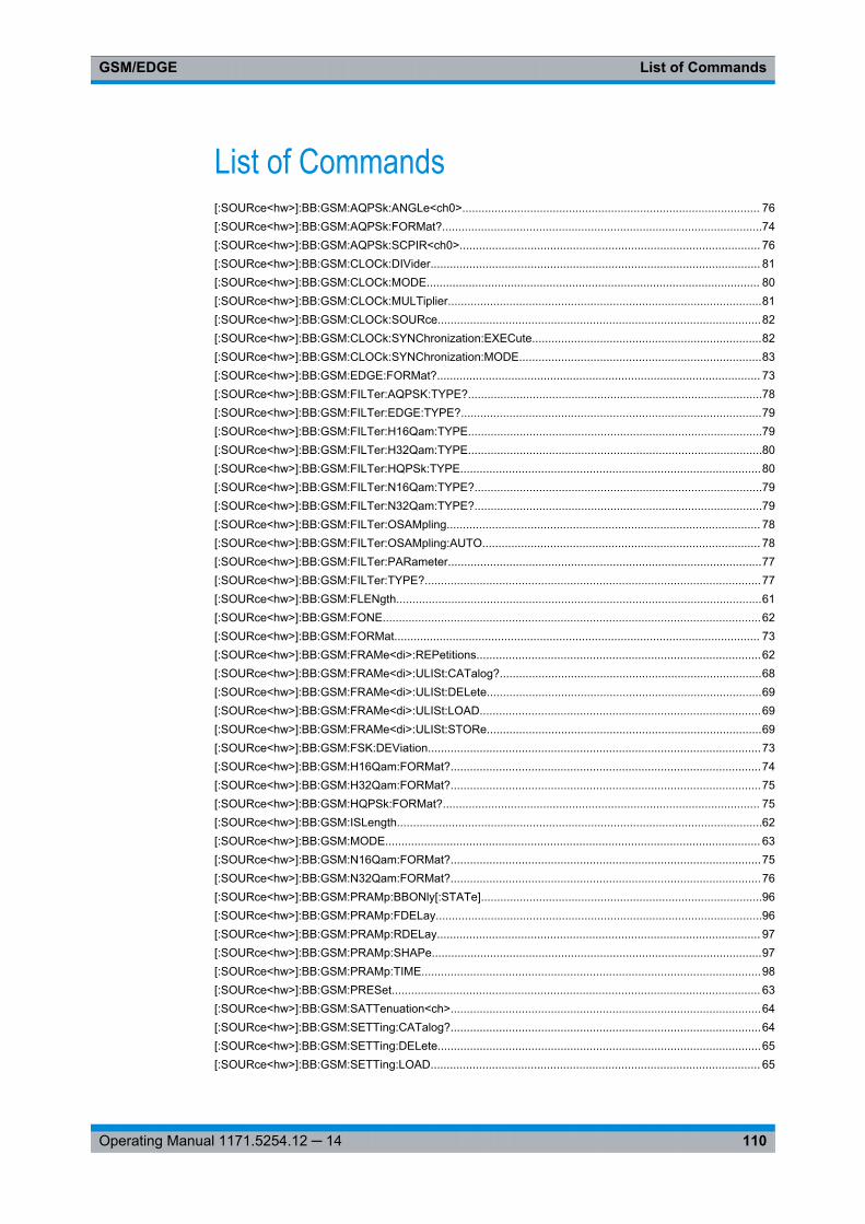
List of CommandsGSM/EDGE
110Operating Manual 1171.5254.12 ─ 14
List of Commands[:SOURce<hw>]:BB:GSM:AQPSk:ANGLe<ch0>............................................................................................ 76[:SOURce<hw>]:BB:GSM:AQPSk:FORMat?...................................................................................................74[:SOURce<hw>]:BB:GSM:AQPSk:SCPIR<ch0>............................................................................................. 76[:SOURce<hw>]:BB:GSM:CLOCk:DIVider...................................................................................................... 81[:SOURce<hw>]:BB:GSM:CLOCk:MODE....................................................................................................... 80[:SOURce<hw>]:BB:GSM:CLOCk:MULTiplier.................................................................................................81[:SOURce<hw>]:BB:GSM:CLOCk:SOURce....................................................................................................82[:SOURce<hw>]:BB:GSM:CLOCk:SYNChronization:EXECute.......................................................................82[:SOURce<hw>]:BB:GSM:CLOCk:SYNChronization:MODE...........................................................................83[:SOURce<hw>]:BB:GSM:EDGE:FORMat?.................................................................................................... 73[:SOURce<hw>]:BB:GSM:FILTer:AQPSK:TYPE?...........................................................................................78[:SOURce<hw>]:BB:GSM:FILTer:EDGE:TYPE?.............................................................................................79[:SOURce<hw>]:BB:GSM:FILTer:H16Qam:TYPE...........................................................................................79[:SOURce<hw>]:BB:GSM:FILTer:H32Qam:TYPE...........................................................................................80[:SOURce<hw>]:BB:GSM:FILTer:HQPSk:TYPE.............................................................................................80[:SOURce<hw>]:BB:GSM:FILTer:N16Qam:TYPE?.........................................................................................79[:SOURce<hw>]:BB:GSM:FILTer:N32Qam:TYPE?.........................................................................................79[:SOURce<hw>]:BB:GSM:FILTer:OSAMpling................................................................................................. 78[:SOURce<hw>]:BB:GSM:FILTer:OSAMpling:AUTO...................................................................................... 78[:SOURce<hw>]:BB:GSM:FILTer:PARameter.................................................................................................77[:SOURce<hw>]:BB:GSM:FILTer:TYPE?........................................................................................................77[:SOURce<hw>]:BB:GSM:FLENgth.................................................................................................................61[:SOURce<hw>]:BB:GSM:FONE.....................................................................................................................62[:SOURce<hw>]:BB:GSM:FORMat................................................................................................................. 73[:SOURce<hw>]:BB:GSM:FRAMe<di>:REPetitions........................................................................................62[:SOURce<hw>]:BB:GSM:FRAMe<di>:ULISt:CATalog?.................................................................................68[:SOURce<hw>]:BB:GSM:FRAMe<di>:ULISt:DELete.....................................................................................69[:SOURce<hw>]:BB:GSM:FRAMe<di>:ULISt:LOAD.......................................................................................69[:SOURce<hw>]:BB:GSM:FRAMe<di>:ULISt:STORe.....................................................................................69[:SOURce<hw>]:BB:GSM:FSK:DEViation.......................................................................................................73[:SOURce<hw>]:BB:GSM:H16Qam:FORMat?................................................................................................74[:SOURce<hw>]:BB:GSM:H32Qam:FORMat?................................................................................................75[:SOURce<hw>]:BB:GSM:HQPSk:FORMat?.................................................................................................. 75[:SOURce<hw>]:BB:GSM:ISLength.................................................................................................................62[:SOURce<hw>]:BB:GSM:MODE.................................................................................................................... 63[:SOURce<hw>]:BB:GSM:N16Qam:FORMat?................................................................................................75[:SOURce<hw>]:BB:GSM:N32Qam:FORMat?................................................................................................76[:SOURce<hw>]:BB:GSM:PRAMp:BBONly[:STATe].......................................................................................96[:SOURce<hw>]:BB:GSM:PRAMp:FDELay.....................................................................................................96[:SOURce<hw>]:BB:GSM:PRAMp:RDELay.................................................................................................... 97[:SOURce<hw>]:BB:GSM:PRAMp:SHAPe......................................................................................................97[:SOURce<hw>]:BB:GSM:PRAMp:TIME.........................................................................................................98[:SOURce<hw>]:BB:GSM:PRESet.................................................................................................................. 63[:SOURce<hw>]:BB:GSM:SATTenuation<ch>................................................................................................64[:SOURce<hw>]:BB:GSM:SETTing:CATalog?................................................................................................64[:SOURce<hw>]:BB:GSM:SETTing:DELete....................................................................................................65[:SOURce<hw>]:BB:GSM:SETTing:LOAD...................................................................................................... 65
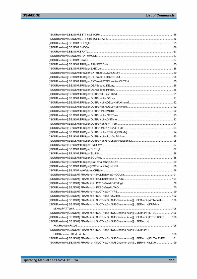
List of CommandsGSM/EDGE
111Operating Manual 1171.5254.12 ─ 14
[:SOURce<hw>]:BB:GSM:SETTing:STORe....................................................................................................65[:SOURce<hw>]:BB:GSM:SETTing:STORe:FAST..........................................................................................66[:SOURce<hw>]:BB:GSM:SLENgth.................................................................................................................61[:SOURce<hw>]:BB:GSM:SMODe.................................................................................................................. 66[:SOURce<hw>]:BB:GSM:SRATe................................................................................................................... 67[:SOURce<hw>]:BB:GSM:SRATe:MODE........................................................................................................67[:SOURce<hw>]:BB:GSM:STATe....................................................................................................................67[:SOURce<hw>]:BB:GSM:TRIGger:ARM:EXECute........................................................................................ 85[:SOURce<hw>]:BB:GSM:TRIGger:EXECute................................................................................................. 85[:SOURce<hw>]:BB:GSM:TRIGger:EXTernal:CLOCk:DELay.........................................................................89[:SOURce<hw>]:BB:GSM:TRIGger:EXTernal:CLOCk:INHibit.........................................................................90[:SOURce<hw>]:BB:GSM:TRIGger:EXTernal:SYNChronize:OUTPut............................................................ 85[:SOURce<hw>]:BB:GSM:TRIGger:OBASeband:DELay................................................................................ 86[:SOURce<hw>]:BB:GSM:TRIGger:OBASeband:INHibit................................................................................ 86[:SOURce<hw>]:BB:GSM:TRIGger:OUTPut:DELay:FIXed.............................................................................91[:SOURce<hw>]:BB:GSM:TRIGger:OUTPut<ch>:DELay............................................................................... 91[:SOURce<hw>]:BB:GSM:TRIGger:OUTPut<ch>:DELay:MAXimum?............................................................92[:SOURce<hw>]:BB:GSM:TRIGger:OUTPut<ch>:DELay:MINimum?.............................................................92[:SOURce<hw>]:BB:GSM:TRIGger:OUTPut<ch>:MODE............................................................................... 92[:SOURce<hw>]:BB:GSM:TRIGger:OUTPut<ch>:OFFTime...........................................................................93[:SOURce<hw>]:BB:GSM:TRIGger:OUTPut<ch>:ONTime.............................................................................93[:SOURce<hw>]:BB:GSM:TRIGger:OUTPut<ch>:PATTern............................................................................94[:SOURce<hw>]:BB:GSM:TRIGger:OUTPut<ch>:PERiod:SLOT....................................................................94[:SOURce<hw>]:BB:GSM:TRIGger:OUTPut<ch>:PERiod[:FRAMe]...............................................................94[:SOURce<hw>]:BB:GSM:TRIGger:OUTPut<ch>:PULSe:DIVider..................................................................95[:SOURce<hw>]:BB:GSM:TRIGger:OUTPut<ch>:PULSe[:FREQuency]?...................................................... 95[:SOURce<hw>]:BB:GSM:TRIGger:RMODe?................................................................................................. 87[:SOURce<hw>]:BB:GSM:TRIGger:SLENgth..................................................................................................87[:SOURce<hw>]:BB:GSM:TRIGger:SLUNit.....................................................................................................88[:SOURce<hw>]:BB:GSM:TRIGger:SOURce..................................................................................................88[:SOURce<hw>]:BB:GSM:TRIGger[:EXTernal<ch>]:DELay........................................................................... 89[:SOURce<hw>]:BB:GSM:TRIGger[:EXTernal<ch>]:INHibit........................................................................... 89[:SOURce<hw>]:BB:GSM:WAVeform:CREate................................................................................................68[:SOURce<hw>]:BB:GSM[:FRAMe<di>]:MULTislot<st0>:COUNt.................................................................101[:SOURce<hw>]:BB:GSM[:FRAMe<di>]:MULTislot<st0>:STATe................................................................. 104[:SOURce<hw>]:BB:GSM[:FRAMe<di>]:PREDefined:CATalog?....................................................................70[:SOURce<hw>]:BB:GSM[:FRAMe<di>]:PREDefined:LOAD.......................................................................... 70[:SOURce<hw>]:BB:GSM[:FRAMe<di>]:SLOT<st0>:TYPE............................................................................99[:SOURce<hw>]:BB:GSM[:FRAMe<di>]:SLOT<st0>:VOJitter...................................................................... 102[:SOURce<hw>]:BB:GSM[:FRAMe<di>]:SLOT<st0>[:SUBChannel<us>][:USER<ch>]:ATTenuation..........100[:SOURce<hw>]:BB:GSM[:FRAMe<di>]:SLOT<st0>[:SUBChannel<us>][:USER<ch>]:DUMMy:
MIXed:PATTern?.....................................................................................................................................108[:SOURce<hw>]:BB:GSM[:FRAMe<di>]:SLOT<st0>[:SUBChannel<us>][:USER<ch>]:ETSC.....................106[:SOURce<hw>]:BB:GSM[:FRAMe<di>]:SLOT<st0>[:SUBChannel<us>][:USER<ch>]:ETSC:USER..........106[:SOURce<hw>]:BB:GSM[:FRAMe<di>]:SLOT<st0>[:SUBChannel<us>][:USER<ch>]:
FCORrection:FIXed.................................................................................................................................108[:SOURce<hw>]:BB:GSM[:FRAMe<di>]:SLOT<st0>[:SUBChannel<us>][:USER<ch>]:
FCORrection:FIXed:PATTern..................................................................................................................108[:SOURce<hw>]:BB:GSM[:FRAMe<di>]:SLOT<st0>[:SUBChannel<us>][:USER<ch>]:FILTer:TYPE..........101[:SOURce<hw>]:BB:GSM[:FRAMe<di>]:SLOT<st0>[:SUBChannel<us>][:USER<ch>]:LEVel.......................99
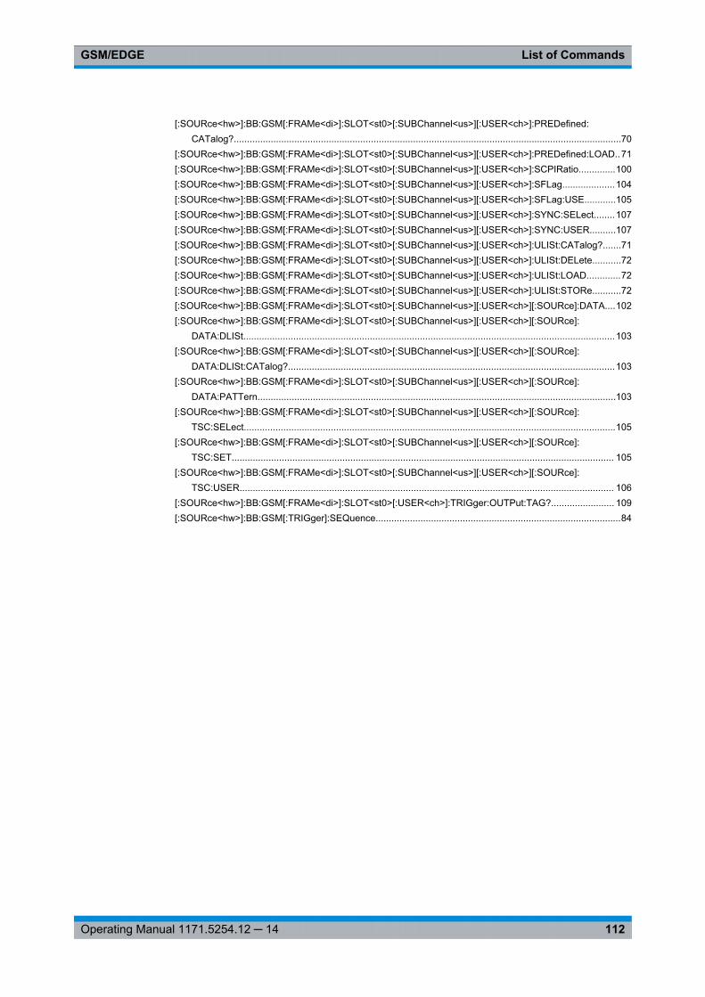
List of CommandsGSM/EDGE
112Operating Manual 1171.5254.12 ─ 14
[:SOURce<hw>]:BB:GSM[:FRAMe<di>]:SLOT<st0>[:SUBChannel<us>][:USER<ch>]:PREDefined:CATalog?...................................................................................................................................................70
[:SOURce<hw>]:BB:GSM[:FRAMe<di>]:SLOT<st0>[:SUBChannel<us>][:USER<ch>]:PREDefined:LOAD..71[:SOURce<hw>]:BB:GSM[:FRAMe<di>]:SLOT<st0>[:SUBChannel<us>][:USER<ch>]:SCPIRatio..............100[:SOURce<hw>]:BB:GSM[:FRAMe<di>]:SLOT<st0>[:SUBChannel<us>][:USER<ch>]:SFLag....................104[:SOURce<hw>]:BB:GSM[:FRAMe<di>]:SLOT<st0>[:SUBChannel<us>][:USER<ch>]:SFLag:USE............105[:SOURce<hw>]:BB:GSM[:FRAMe<di>]:SLOT<st0>[:SUBChannel<us>][:USER<ch>]:SYNC:SELect........107[:SOURce<hw>]:BB:GSM[:FRAMe<di>]:SLOT<st0>[:SUBChannel<us>][:USER<ch>]:SYNC:USER..........107[:SOURce<hw>]:BB:GSM[:FRAMe<di>]:SLOT<st0>[:SUBChannel<us>][:USER<ch>]:ULISt:CATalog?.......71[:SOURce<hw>]:BB:GSM[:FRAMe<di>]:SLOT<st0>[:SUBChannel<us>][:USER<ch>]:ULISt:DELete...........72[:SOURce<hw>]:BB:GSM[:FRAMe<di>]:SLOT<st0>[:SUBChannel<us>][:USER<ch>]:ULISt:LOAD.............72[:SOURce<hw>]:BB:GSM[:FRAMe<di>]:SLOT<st0>[:SUBChannel<us>][:USER<ch>]:ULISt:STORe...........72[:SOURce<hw>]:BB:GSM[:FRAMe<di>]:SLOT<st0>[:SUBChannel<us>][:USER<ch>][:SOURce]:DATA....102[:SOURce<hw>]:BB:GSM[:FRAMe<di>]:SLOT<st0>[:SUBChannel<us>][:USER<ch>][:SOURce]:
DATA:DLISt.............................................................................................................................................103[:SOURce<hw>]:BB:GSM[:FRAMe<di>]:SLOT<st0>[:SUBChannel<us>][:USER<ch>][:SOURce]:
DATA:DLISt:CATalog?............................................................................................................................103[:SOURce<hw>]:BB:GSM[:FRAMe<di>]:SLOT<st0>[:SUBChannel<us>][:USER<ch>][:SOURce]:
DATA:PATTern........................................................................................................................................103[:SOURce<hw>]:BB:GSM[:FRAMe<di>]:SLOT<st0>[:SUBChannel<us>][:USER<ch>][:SOURce]:
TSC:SELect.............................................................................................................................................105[:SOURce<hw>]:BB:GSM[:FRAMe<di>]:SLOT<st0>[:SUBChannel<us>][:USER<ch>][:SOURce]:
TSC:SET................................................................................................................................................. 105[:SOURce<hw>]:BB:GSM[:FRAMe<di>]:SLOT<st0>[:SUBChannel<us>][:USER<ch>][:SOURce]:
TSC:USER.............................................................................................................................................. 106[:SOURce<hw>]:BB:GSM[:FRAMe<di>]:SLOT<st0>[:USER<ch>]:TRIGger:OUTPut:TAG?........................ 109[:SOURce<hw>]:BB:GSM[:TRIGger]:SEQuence.............................................................................................84
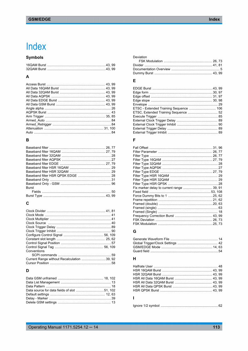
IndexGSM/EDGE
113Operating Manual 1171.5254.12 ─ 14
Index
Symbols
16QAM Burst ...............................................................43, 9932QAM Burst ...............................................................43, 99
A
Access Burst ............................................................... 43, 99All Data 16QAM Burst ................................................. 43, 99All Data 32QAM Burst ................................................. 43, 99All Data AQPSK .......................................................... 43, 99All Data EDGE Burst ................................................... 43, 99All Data GSM Burst ..................................................... 43, 99Angle alpha ....................................................................... 26AQPSK Burst .................................................................... 43Arm Trigger ................................................................. 35, 85Armed_Auto ...................................................................... 84Armed_Retrigger ............................................................... 84Attenuation ................................................................ 31, 100Auto ................................................................................... 84
B
Baseband filter ............................................................ 26, 77Baseband filter 16QAM ............................................... 27, 79Baseband filter 32QAM ..................................................... 28Baseband filter AQPSK ..................................................... 27Baseband filter EDGE ................................................. 27, 79Baseband filter HSR 16QAM ............................................ 29Baseband filter HSR 32QAM ............................................ 29Baseband filter HSR QPSK EDGE ................................... 28Baseband Only ..................................................................31Baseband Only - GSM ...................................................... 96Burst
Fields .......................................................................... 50Burst Type ................................................................... 43, 99
C
Clock Divider ............................................................... 41, 81Clock Mode ....................................................................... 41Clock Multiplier .................................................................. 41Clock Source .................................................................... 40Clock Trigger Delay ...........................................................89Clock Trigger Inhibit .......................................................... 90Configure Control Signal ........................................... 56, 109Constant slot length .................................................... 25, 62Control Signal Position ...................................................... 57Control Signal Tag .................................................... 56, 109Conventions
SCPI commands ......................................................... 59Current Range without Recalculation ..........................39, 92Cursor Position ..................................................................58
D
Data GSM unframed ................................................. 18, 102Data List Management ...................................................... 13Data Pattern ...................................................................... 18Data source for data fields of slot ..............................51, 102Default settings ........................................................... 12, 63Delay - Marker ...................................................................39Delete GSM settings ......................................................... 13
DeviationFSK Modulation .................................................... 26, 73
Divider ......................................................................... 41, 81Documentation Overview .................................................... 5Dummy Burst .............................................................. 43, 99
E
EDGE Burst .................................................................43, 99Edge form ....................................................................30, 97Edge offset .................................................................. 31, 97Edge slope .................................................................. 30, 98Envelope ........................................................................... 29ETSC - Extended Training Sequence ............................. 106ETSC, Extended Training Sequence ................................ 52Execute Trigger ................................................................. 85External Clock Trigger Delay ............................................ 89External Clock Trigger Inhibit ............................................ 90External Trigger Delay ...................................................... 89External Trigger Inhibit ...................................................... 89
F
Fall Offset .................................................................... 31, 96Filter Parameter .......................................................... 26, 77Filter Type ................................................................... 26, 77Filter Type 16QAM ...................................................... 27, 79Filter Type 32QAM ............................................................ 28Filter Type AQPSK ............................................................ 27Filter Type EDGE ........................................................ 27, 79Filter Type HSR 16QAM ................................................... 29Filter Type HSR 32QAM ................................................... 29Filter Type HSR QPSK ......................................................28Fix marker delay to current range ............................... 39, 91Fixed field .................................................................. 53, 108Force Dummy Bits to 1 ................................................25, 62Frame repetition .......................................................... 21, 62Framed (double) ..........................................................20, 63Framed (single) ................................................................. 63Framed (Single) ................................................................ 18Frequency Correction Burst ........................................ 43, 99FSK Deviation ............................................................. 26, 73FSK Modulation ...........................................................25, 73
G
Generate Waveform File ................................................... 14Global Trigger/Clock Settings ........................................... 42GSM/EDGE Mode ....................................................... 14, 63Guard field .........................................................................54
H
Halfrate User ..................................................................... 48HSR 16QAM Burst ...................................................... 43, 99HSR 32QAM Burst ...................................................... 43, 99HSR All Data 16QAM Burst ........................................ 43, 99HSR All Data 32QAM Burst ........................................ 43, 99HSR All Data QPSK Burst ...........................................43, 99HSR QPSK Burst ........................................................ 43, 99
I
Ignore 1/2 symbol ..............................................................62
IndexGSM/EDGE
114Operating Manual 1171.5254.12 ─ 14
Ignore 1/4 symbol ........................................................25, 62Ignore ½ symbol ................................................................25
L
Length of pseudo-random bit string ............................ 18, 51Level Attenuation ...................................................... 31, 100Load GSM settings ............................................................13
M
Manual trigger ................................................................... 85Marker Delay ............................................................... 39, 91Marker Mode ............................................................... 38, 92Marker Period ..............................................................38, 94Marker Positions ............................................................... 57Marker Signal Tag ..................................................... 56, 109Measured external clock ................................................... 41Mixed-Field ................................................................54, 108Mode Framed (double) ................................................20, 63Mode Framed (single) ....................................................... 63Mode Framed (Single) ...................................................... 18Mode Unframed .......................................................... 16, 63Modulation Type ..........................................................25, 73Modulation Type 16QAM ............................................ 27, 75Modulation Type 32QAM ............................................ 28, 76Modulation Type AQPSK .................................................. 26Modulation Type EDGE .............................................. 27, 73Modulation Type HSR 16QAM .................................... 28, 74Modulation Type HSR 32QAM .................................... 29, 75Modulation Type HSR QPSK ...................................... 28, 75MSK Modulation .......................................................... 25, 73Multiplier ............................................................................ 41Multislot Configuration State ..................................... 49, 104
N
NORMAL (Half Rate) Burst ......................................... 43, 99Normal AQPSK ................................................................. 43NORMAL Burst ........................................................... 43, 99Number of Slots ........................................................ 49, 101
O
ON/OFF Ratio Marker ................................................. 38, 93Oversampling .............................................................. 25, 78Oversampling Auto State .................................................. 78
P
Pattern .................................................................18, 51, 102Power Ramp Control ......................................................... 29PRBS .......................................................................... 18, 51Pulse Divider Marker - GSM/EDGE .................................. 95Pulse Frequency Marker ............................................. 38, 95
R
Ramp Function ............................................................ 30, 97Ramp Time ..................................................................30, 98Repetition of Frame ...........................................................62Repetition of Frames ......................................................... 21Retrigger ........................................................................... 84Rise Offset .................................................................. 31, 97Running - Trigger ........................................................ 35, 87
S
Save GSM settings ........................................................... 13Save/Recall ....................................................................... 13Save/Recall Frames .................................................... 20, 21SCPIR ......................................................................... 26, 48Select Ramp to Edit .......................................................... 56Sequence Length ........................................................ 15, 61Set Synchronization Settings ..................................... 40, 82Set to default ............................................................... 12, 63Signal Duration - Trigger ............................................. 35, 87Signal Duration Unit - Trigger ......................................34, 88Simulation Mode ......................................................... 17, 66Slot Attenuation ................................................... 31, 49, 100Slot Level .................................................................... 48, 99Slot Marker Definition ........................................................ 55Standard settings ........................................................ 12, 63State ............................................................................ 12, 67Stealing Flag ............................................................. 51, 104Stopped ............................................................................. 35Subchannel Power Imbalance Ratio ........................... 26, 48Symbol Rate ................................................................24, 67Symbol Rate Mode ......................................................15, 67Sync. Output to External Trigger ....................................... 36Synchronization Burst ................................................. 43, 99Synchronization mode .......................................................40Synchronization Mode .......................................................83
T
Tail data field ..................................................................... 50Timing jitter
VAMOS ....................................................................... 50Training Sequence .................................................... 52, 105Training Sequence Sync ................................................... 53Training Sequence Sync-Access Burst ........................... 107Trigger Delay .....................................................................37Trigger Delay External ...................................................... 89Trigger Delay Other Baseband ......................................... 86Trigger Inhibit .................................................................... 37Trigger Inhibit External ...................................................... 89Trigger Inhibit Other Baseband ......................................... 86Trigger Mode ..................................................................... 84
Armed ......................................................................... 34Auto ............................................................................ 34Retrigger ..................................................................... 34Single .......................................................................... 34
Trigger parameters ............................................................32Trigger Source .................................................................. 35TSC ........................................................................... 52, 105
U
Unframed .................................................................... 16, 63Use TSC ............................................................................52User ETSC ................................................................ 52, 106User Marker / AUX I/O Settings ........................................ 42User Sync-Access Burst ................................................... 53User TSC ................................................................ 105, 106
V
VAMOSFading from burst to burst ...........................................50
VAMOS offset jitter ............................................................50
IndexGSM/EDGE
115Operating Manual 1171.5254.12 ─ 14
W
Waveform File ................................................................... 14