Embed Size (px)
Citation preview

1xEV-DO Rev. A/Rev. BDigital Standard forR&S®Signal GeneratorsOperating Manual
Oper
ating
Man
ual
1171.5631.12 ─ 16(;ÕÆO<)
Test
& Me
asur
emen
t
This document describes the following software options:
● R&S®SMBV-K47/-K871415.8090.xx, 1415.8719.02
● R&S®SMU-K47/-K871408.7410.02, 1408.8675.02
● R&S®AMU-K47/-K871402.6602.02, 1403.0999.02
● R&S®SMATE-K47/-K871404.7900.02, 1404.8887.02
● R&S®SMJ-K47/-K871409.2306.02, 1409.3548.02
This manual version corresponds to firmware version:FW 3.50.082.xx and later of the R&S®SMBV100AFW 3.20.286.xx and later of the R&S®SMU200A, R&S®SMATE200A, R&S®SMJ100A and R&S®AMU200A
© 2016 Rohde & Schwarz GmbH & Co. KGMühldorfstr. 15, 81671 München, GermanyPhone: +49 89 41 29 - 0Fax: +49 89 41 29 12 164Email: [email protected]: www.rohde-schwarz.comSubject to change – Data without tolerance limits is not binding.R&S® is a registered trademark of Rohde & Schwarz GmbH & Co. KG.Trade names are trademarks of the owners.
The following abbreviations are used throughout this manual: R&S®SMBV100A is abbreviated as R&S SMBV, R&S®SMU200A isabbreviated as R&S SMU, R&S®AMU200A is abbreviated as R&S AMU, R&S®SMATE200A is abbreviated as R&S SMATE,R&S®SMJ100A is abbreviated as R&S SMJ,R&S®WinIQSIM2TM is abbreviated as R&S WinIQSIM2; the license types02/03/07/11/13/16/12 are abbreviated as xx.
Contents1xEV-DO Rev. A/Rev. B
3Operating Manual 1171.5631.12 ─ 16
Contents1 Preface.................................................................................................... 5
1.1 Documentation Overview............................................................................................. 5
1.2 Conventions Used in the Documentation...................................................................6
1.2.1 Typographical Conventions.............................................................................................6
1.2.2 Notes on Screenshots.....................................................................................................7
1.2.3 Naming of Software Options........................................................................................... 7
2 About the 1xEV-DO Options................................................................. 82.1 Traffic Scheduling Process........................................................................................10
3 1xEV-DO User Interface.......................................................................113.1 General Settings..........................................................................................................12
3.2 Access Network Settings........................................................................................... 15
3.3 Multi-Carrier Configuration Settings......................................................................... 18
3.4 Traffic Channel Settings.............................................................................................20
3.5 Access Terminal Settings.......................................................................................... 31
3.6 Filter / Clipping / ARB Settings.................................................................................. 44
3.6.1 Filter Settings................................................................................................................ 44
3.6.2 Clipping Settings........................................................................................................... 45
3.6.3 ARB Settings.................................................................................................................46
3.6.4 I/Q Setting..................................................................................................................... 46
3.7 Trigger/Marker/Clock Settings................................................................................... 47
3.7.1 Trigger Settings.............................................................................................................48
3.7.2 Marker Settings............................................................................................................. 51
3.7.3 Marker Delay Settings...................................................................................................52
3.7.4 Clock Settings............................................................................................................... 52
3.7.5 Global Settings..............................................................................................................54
4 Remote-Control Commands............................................................... 554.1 Programming Examples............................................................................................. 56
4.2 General Commands.................................................................................................... 60
4.3 Filter/Clipping/ARB Commands.................................................................................63
4.4 Trigger Commands..................................................................................................... 68

Contents1xEV-DO Rev. A/Rev. B
4Operating Manual 1171.5631.12 ─ 16
4.5 Marker Commands......................................................................................................72
4.6 Clock Commands........................................................................................................74
4.7 Access Network Commands......................................................................................76
4.8 Multi-Carrier Configuration Commands....................................................................81
4.9 Configure Traffic User Commands............................................................................83
4.10 Configure Access Terminal Commands................................................................... 93
List of Commands..............................................................................115
Index....................................................................................................119
Preface1xEV-DO Rev. A/Rev. B
5Operating Manual 1171.5631.12 ─ 16
1 Preface
1.1 Documentation Overview
This section provides an overview of the R&S Signal Generator user documentation.You find it on the product page at:
http://www.rohde-schwarz.com/product/SMBV100A.html > "Downloads"
Quick start guide
Introduces the R&S Signal Generator and describes how to set up and start workingwith the product. Includes basic operations, typical measurement examples, and gen-eral information, e.g. safety instructions, etc. A printed version is delivered with theinstrument.
Online help
Offers quick, context-sensitive access to the complete information for the base unit andthe software options directly on the instrument.
Operating manual
Separate manuals for the base unit and the software options are provided for down-load:● Base unit manual
Contains the description of all instrument modes and functions. It also provides anintroduction to remote control, a complete description of the remote control com-mands with programming examples, and information on maintenance, instrumentinterfaces and error messages. Includes the contents of the quick start guide man-ual.
● Software option manualContains the description of the specific functions of an option. Basic information onoperating the R&S Signal Generator is not included.
The online version of the operating manual provides the complete contents for imme-diate display on the Internet.
Service manual
Describes the performance test for checking the rated specifications, module replace-ment and repair, firmware update, troubleshooting and fault elimination, and containsmechanical drawings and spare part lists.
The service manual is available for registered users on the global Rohde & Schwarzinformation system (GLORIS, https://gloris.rohde-schwarz.com).
Documentation Overview

Preface1xEV-DO Rev. A/Rev. B
6Operating Manual 1171.5631.12 ─ 16
Instrument security procedures manual
Deals with security issues when working with the R&S Signal Generator in secureareas.
Basic safety instructions
Contains safety instructions, operating conditions and further important information.The printed document is delivered with the instrument.
Data sheet and brochure
The data sheet contains the technical specifications of the software options, see "Digi-tal Standards for Signal Generators - Data sheet" on the web site. It also lists theoptions and their order numbers.
The brochure provides an overview of the instrument and deals with the specific char-acteristics.
Release notes and open source acknowledgment (OSA)
The release notes of the base units list new features, improvements and known issuesof the current firmware version, and describe the firmware installation.
The open source acknowledgment document provides verbatim license texts of theused open source software. See the product page of the base unit, e.g. at:
http://www.rohde-schwarz.com/product/SMBV100A.html > "Downloads" > "Firmware"
Application Notes, Application Cards, White Papers, etc.
These documents deal with special applications or background information on particu-lar topics, see http://www.rohde-schwarz.com/appnotes.
1.2 Conventions Used in the Documentation
1.2.1 Typographical Conventions
The following text markers are used throughout this documentation:
Convention Description
"Graphical user interface ele-ments"
All names of graphical user interface elements on the screen, such asdialog boxes, menus, options, buttons, and softkeys are enclosed byquotation marks.
KEYS Key names are written in capital letters.
File names, commands,program code
File names, commands, coding samples and screen output are distin-guished by their font.
Input Input to be entered by the user is displayed in italics.
Conventions Used in the Documentation

Preface1xEV-DO Rev. A/Rev. B
7Operating Manual 1171.5631.12 ─ 16
Convention Description
Links Links that you can click are displayed in blue font.
"References" References to other parts of the documentation are enclosed by quota-tion marks.
1.2.2 Notes on Screenshots
When describing the functions of the product, we use sample screenshots. Thesescreenshots are meant to illustrate as much as possible of the provided functions andpossible interdependencies between parameters. The shown values may not representrealistic test situations.
The screenshots usually show a fully equipped product, that is: with all options instal-led. Thus, some functions shown in the screenshots may not be available in your par-ticular product configuration.
1.2.3 Naming of Software Options
In this operating manual, we explicitly refer to options required for specific functions ofthe digital standard.
The name of software options for signal generators vary in the name of the instrument,but the option name is identical. Therefore we use in this manual the placeholderR&S SMx/AMU.
Example: Naming for an option of the vector signal generator R&S SMBV100A, e.g:● R&S SMx/AMU-K99, stands for R&S SMBV-K99
The particular software options available for the corresponding instruments are listedon the back of the title page.
Conventions Used in the Documentation
About the 1xEV-DO Options1xEV-DO Rev. A/Rev. B
8Operating Manual 1171.5631.12 ─ 16
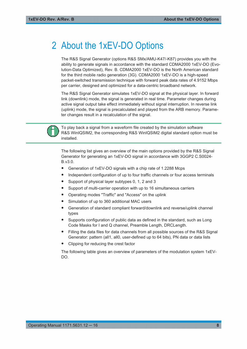
2 About the 1xEV-DO OptionsThe R&S Signal Generator (options R&S SMx/AMU-K47/-K87) provides you with theability to generate signals in accordance with the standard CDMA2000 1xEV-DO (Evo-lution-Data Optimized), Rev. B. CDMA2000 1xEV-DO is the North American standardfor the third mobile radio generation (3G). CDMA2000 1xEV-DO is a high-speedpacket-switched transmission technique with forward peak data rates of 4.9152 Mbpsper carrier, designed and optimized for a data-centric broadband network.
The R&S Signal Generator simulates 1xEV-DO signal at the physical layer. In forwardlink (downlink) mode, the signal is generated in real time. Parameter changes duringactive signal output take effect immediately without signal interruption. In reverse link(uplink) mode, the signal is precalculated and played from the ARB memory. Parame-ter changes result in a recalculation of the signal.
To play back a signal from a waveform file created by the simulation softwareR&S WinIQSIM2, the corresponding R&S WinIQSIM2 digital standard option must beinstalled.
The following list gives an overview of the main options provided by the R&S SignalGenerator for generating an 1xEV-DO signal in accordance with 3GGP2 C.S0024-B.v3.0.● Generation of 1xEV-DO signals with a chip rate of 1.2288 Mcps● Independent configuration of up to four traffic channels or four access terminals● Support of physical layer subtypes 0, 1, 2 and 3● Support of multi-carrier operation with up to 16 simultaneous carriers● Operating modes "Traffic" and "Access" on the uplink● Simulation of up to 360 additional MAC users● Generation of standard compliant forward/downlink and reverse/uplink channel
types● Supports configuration of public data as defined in the standard, such as Long
Code Masks for I and Q channel, Preamble Length, DRCLength.● Filling the data files for data channels from all possible sources of the R&S Signal
Generator: pattern (all1, all0, user-defined up to 64 bits), PN data or data lists● Clipping for reducing the crest factor
The following table gives an overview of parameters of the modulation system 1xEV-DO.

About the 1xEV-DO Options1xEV-DO Rev. A/Rev. B
9Operating Manual 1171.5631.12 ─ 16
Table 2-1: Parameters of the modulation system 1xEV-DO
Parameter Value
Chip rate 1.2288 Mcps
Channel types Forward link:● Pilot Channel● Forward Traffic Channel (Rev. A)● Reverse Activity● DRCLock● Reverse Power Control● ARQ (Rev. A)● Control Channel
Reverse link, access mode:● Pilot Channel● Data Channel
Reverse link, traffic mode:● Pilot Channel● Auxiliary Pilot Channel (Rev. A)● Reverse Rate Indicator● Data Rate Control● Data Source Control (Rev. A)● ACK Channel● Data Channel
Generation mode Forward link:● Realtime mode
Reverse link:● Arbitrary waveform mode● Multicarrier operation
Up to 16 concurrent carriers supportedRequires option R&S SMx/AMU-K87
Data rates Forward link:● 38.4 .. 2457.6 kbps (Rev. 0)● 4.8 .. 3072 kbps (Rev. A)● 4.8 .. 4915 kbps (Rev. B)
Requires option R&S SMx/AMU-K87
Reverse link:● 9.6 .. 153.6 kbps (Rev. 0)● 4.8 .. 1843.2 kbps (Rev. A)
Frame length 26.67 ms (1 frame = 16 slots)
Slot duration 1.67 ms (1 slot = 2048 PN chips)
PN offset 0 .. 511
Channel coding All channel coding modes defined in the standard (channel encoding,block interleaving, repetition, modulation, orthogonal spreading byWalsh function)
Modulation BPSK, QPSK, 8PSK, 16QAM, 64QAM
Requires option R&S SMx/AMU-K87
Multi-code modulation B4, Q2, Q4, Q4Q2, E4E2
Long Code Mask Separate Long Code Masks for I and Q channel. The Long Code Gen-erator is reloaded at every PN rollover with 0x24B91BFD3A8.
Walsh covers Different Walsh functions for the different channels
About the 1xEV-DO Options1xEV-DO Rev. A/Rev. B
10Operating Manual 1171.5631.12 ─ 16
2.1 Traffic Scheduling Process
In the 1xEV-DO system, the Forward Link is governed by a time division multipleaccess technique. Access to Forward Link bandwidth by a user channel is governed bya scheduling process. The schedule process determines who gets access to ForwardLink slots to carry user data.
The traffic scheduling process in this instrument follows a number of rules to schedulewhich user's data is sent for each slot.
The rules are listed in order of priority, with the highest priority rules being listed first. Inthe event that two rules contradict each other, the circumstances invoking the lowerpriority rule must be altered to resolve the contradiction.● A channel with "State = Off" is never transmitted.● The first slot of the control channel packet is always transmitted at its specified off-
set at the start of the control channel cycle.● Once the first slot of a multiple slot packet is sent, the remaining slots are always
transmitted with the proper interlace (three slots skipped after one slot sent).● Packets for a user can be transmitted on 1 to 4 interlaces (there are a total of 4
interlaces in the 1xEV-DO system). Packets on the different interlaces are dupli-cates of the packets sent on the other interlaces for a given user. The interleavefactor user interface parameter is used to control the number of interlaces used foreach user.
● Immediately after the transmission of the last slot of a multiple slot packet, a lock-out period of three slots is created. No additional packets from the same sourcecan be scheduled before the three slot period expires.
● A control channel packet has priority over all other traffic channels. This excludestransmission of user channels in advance of the control channel packet, if the otherchannel would require a slot that the control channel packet would require.
● User1 traffic has priority over User2, User3, and User4 traffic.● User2 traffic has priority over User3 and User4 traffic.● User3 traffic has priority over User4 traffic.● If no traffic is scheduled for a slot, an idle slot is transmitted.
Traffic Scheduling Process
1xEV-DO User Interface1xEV-DO Rev. A/Rev. B
11Operating Manual 1171.5631.12 ─ 16
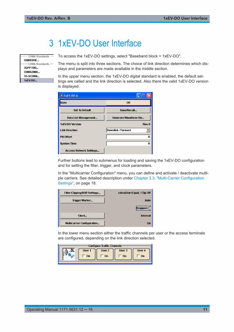
3 1xEV-DO User InterfaceTo access the 1xEV-DO settings, select "Baseband block > 1xEV-DO".
The menu is split into three sections. The choice of link direction determines which dis-plays and parameters are made available in the middle section.
In the upper menu section, the 1xEV-DO digital standard is enabled, the default set-tings are called and the link direction is selected. Also there the valid 1xEV-DO versionis displayed.
Further buttons lead to submenus for loading and saving the 1xEV-DO configurationand for setting the filter, trigger, and clock parameters.
In the "Multicarrier Configuration" menu, you can define and activate / deactivate multi-ple carriers. See detailed description under Chapter 3.3, "Multi-Carrier ConfigurationSettings", on page 18.
In the lower menu section either the traffic channels per user or the access terminalsare configured, depending on the link direction selected.
1xEV-DO User Interface1xEV-DO Rev. A/Rev. B
12Operating Manual 1171.5631.12 ─ 16
3.1 General Settings
With this dialog, the 1xEV-DO digital standard is enabled and reset, and all the settingsvalid for the signal in both link directions are made.
StateActivates the standard and deactivates all the other digital standards and digital modu-lation modes in the same path.
Remote command: [:SOURce<hw>]:BB:EVDO:STATe on page 62
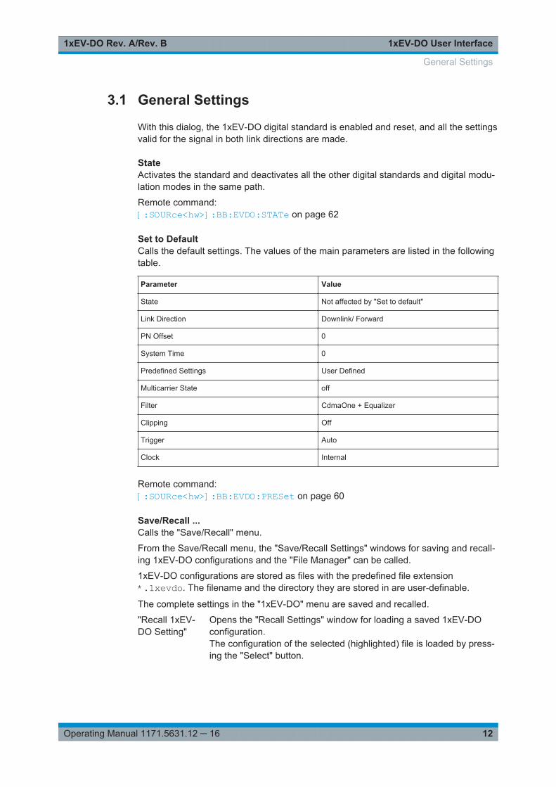
Set to DefaultCalls the default settings. The values of the main parameters are listed in the followingtable.
Parameter Value
State Not affected by "Set to default"
Link Direction Downlink/ Forward
PN Offset 0
System Time 0
Predefined Settings User Defined
Multicarrier State off
Filter CdmaOne + Equalizer
Clipping Off
Trigger Auto
Clock Internal
Remote command: [:SOURce<hw>]:BB:EVDO:PRESet on page 60
Save/Recall ...Calls the "Save/Recall" menu.
From the Save/Recall menu, the "Save/Recall Settings" windows for saving and recall-ing 1xEV-DO configurations and the "File Manager" can be called.
1xEV-DO configurations are stored as files with the predefined file extension*.1xevdo. The filename and the directory they are stored in are user-definable.
The complete settings in the "1xEV-DO" menu are saved and recalled.
"Recall 1xEV-DO Setting"
Opens the "Recall Settings" window for loading a saved 1xEV-DOconfiguration.The configuration of the selected (highlighted) file is loaded by press-ing the "Select" button.
General Settings
1xEV-DO User Interface1xEV-DO Rev. A/Rev. B
13Operating Manual 1171.5631.12 ─ 16
"Save 1xEV-DO Setting"
Opens the "Save Settings" window for saving the current 1xEV-DOsignal configuration.The name of the file is specified in the filename entry field, the direc-tory selected in the save into field. The file is saved by pressing the"Save" button.
"File Manager" Calls the "File Manager".The "File Manager" is used to copy, delete and rename files and tocreate directories.
Remote command: [:SOURce<hw>]:BB:EVDO:SETTing:CATalog? on page 61[:SOURce<hw>]:BB:EVDO:SETTing:LOAD on page 61[:SOURce<hw>]:BB:EVDO:SETTing:STORe on page 61[:SOURce<hw>]:BB:EVDO:SETTing:DELete on page 61
Data List ManagementCalls the "Data List Management" dialog. This menu is used to create and edit a datalist.
All data lists are stored as files with the predefined file extension *.dm_iqd. The file-name and the directory they are stored in are user-definable.
The data lists must be selected as a data source from the submenus under the individ-ual function.
Note: All data lists are generated and edited by means of the SOURce:BB:DM subsys-tem commands. Files containing data lists usually end with *.dm_iqd. The data listsare selected as a data source for a specific function in the individual subsystems of thedigital standard.
Remote command: [:SOURce<hw>]:BB:EVDO:TERMinal<st>:DCHannel:DATA on page 99[:SOURce<hw>]:BB:EVDO:TERMinal<st>:DCHannel:DATA:DSELectionon page 100[:SOURce<hw>]:BB:EVDO:TERMinal<st>:DCHannel:PACKet<ch>:DATAon page 102[:SOURce<hw>]:BB:EVDO:TERMinal<st>:DCHannel:PACKet<ch>:DATA:DSELection on page 103
Generate Waveform FileWith enabled signal generation, triggers the instrument to store the current settings asan ARB signal in a waveform file. Waveform files can be further processed by the ARBand/or as a multi-carrier or a multi-segment signal.
The filename and the directory it is stored in are user-definable; the predefined fileextension for waveform files is *.wv.
Remote command: [:SOURce<hw>]:BB:EVDO:WAVeform:CREate on page 63
1xEV-DO VersionDisplays the current version of the 1xEV-DO standard.
General Settings
1xEV-DO User Interface1xEV-DO Rev. A/Rev. B
14Operating Manual 1171.5631.12 ─ 16
The default settings and parameters provided are oriented towards the specificationsof the version displayed.
Remote command: [:SOURce<hw>]:BB:EVDO:VERSion? on page 63
Link DirectionSelects the link direction.
The settings of the traffic channels per user and the access terminals are provided inthe following menu section in accordance with the selection.
"Downlink/Forward"The link direction selected is base station to access terminal. The sig-nal corresponds to that of a base station.
"Uplink/Reverse"The link direction selected is access terminal to base station. The sig-nal corresponds to that of an access terminal.
Remote command: [:SOURce<hw>]:BB:EVDO:LINK on page 60
PN OffsetSets the PN Offset of the 1xEV-DO signal.
Remote command: [:SOURce<hw>]:BB:EVDO:PNOFfset on page 60
System TimeSets the System Time value of the 1xEV-DO signal and the base station. The SystemTime value is expressed in units of 1.67 ms intervals (80 ms/ 48).
Note: In uplink, the value selected for system time must be multiple of 16.
Remote command: [:SOURce<hw>]:BB:EVDO:STIMe on page 63
Predefined SettingsUplink only
Enables selection of UL predefined settings for Terminal 1 for faster configuration.
The predefined settings are made according to 3GPP2 C.S0032-A to allow easyreceiver testing.
Remote command: [:SOURce<hw>]:BB:EVDO:PREDefined on page 94
Multicarrier ConfigurationAccess the "Multicarrier Configuration" dialog, see Chapter 3.3, "Multi-Carrier Configu-ration Settings", on page 18.
Access Network SettingsIn Downlink direction, provides access to the "Access Network Settings" dialog (seeChapter 3.2, "Access Network Settings", on page 15).
General Settings
1xEV-DO User Interface1xEV-DO Rev. A/Rev. B
15Operating Manual 1171.5631.12 ─ 16
Configure Traffic ChannelsAppears at downlink only
Activates/deactivates the selected terminal and access the corresponding "ConfigureTraffic User 1 .. 4" dialog (see Chapter 3.4, "Traffic Channel Settings", on page 20).
Remote command: [:SOURce<hw>]:BB:EVDO:USER<st>:STATe on page 92
Configure Access TerminalsAppears at uplink only
Activates/deactivates the selected terminal and access the corresponding "ConfigureAccess Terminal 1 .. 4" dialog (see Chapter 3.5, "Access Terminal Settings",on page 31).
Remote command: [:SOURce<hw>]:BB:EVDO:TERMinal<st>:STATe on page 114
Filter / Clipping / ARB SettingsAccess to the dialog for setting baseband filtering, clipping and the sequence length ofthe arbitrary waveform component (see Chapter 3.6, "Filter / Clipping / ARB Settings",on page 44).
Trigger/MarkerCalls the menu for selecting the trigger source, for configuring the marker signals andfor setting the time delay of an external trigger signal (see Chapter 3.7, "Trigger/Marker/Clock Settings", on page 47).
The currently selected trigger source is displayed to the right of the button.
Execute TriggerFor internal trigger source, executes trigger manually.
Remote command: [:SOURce<hw>]:BB:EVDO:TRIGger:EXECute on page 69
ClockCalls the dialog for selecting the clock source and for setting a delay (see Chapter 3.7,"Trigger/Marker/Clock Settings", on page 47).
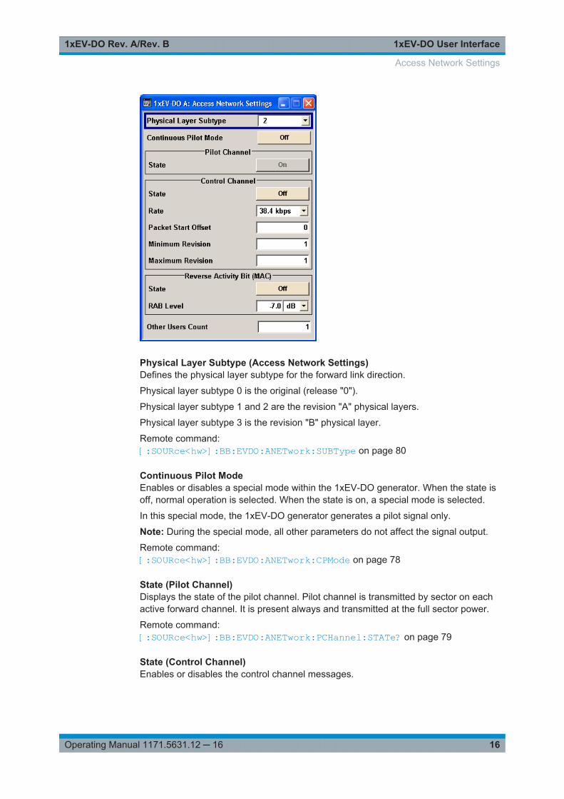
3.2 Access Network Settings
The "Access Network Settings" dialog is available at Downlink only and allows configu-ration of physical layer subtype, the pilot and control channels and reverse activity bit.
"Access Network Settings" consists of three main sections, "Pilot Channel", "ControlChannel" and "Reverse Activity Bit (MAC)".
Access Network Settings
1xEV-DO User Interface1xEV-DO Rev. A/Rev. B
16Operating Manual 1171.5631.12 ─ 16
Physical Layer Subtype (Access Network Settings)Defines the physical layer subtype for the forward link direction.
Physical layer subtype 0 is the original (release "0").
Physical layer subtype 1 and 2 are the revision "A" physical layers.
Physical layer subtype 3 is the revision "B" physical layer.
Remote command: [:SOURce<hw>]:BB:EVDO:ANETwork:SUBType on page 80
Continuous Pilot ModeEnables or disables a special mode within the 1xEV-DO generator. When the state isoff, normal operation is selected. When the state is on, a special mode is selected.
In this special mode, the 1xEV-DO generator generates a pilot signal only.
Note: During the special mode, all other parameters do not affect the signal output.
Remote command: [:SOURce<hw>]:BB:EVDO:ANETwork:CPMode on page 78
State (Pilot Channel)Displays the state of the pilot channel. Pilot channel is transmitted by sector on eachactive forward channel. It is present always and transmitted at the full sector power.
Remote command: [:SOURce<hw>]:BB:EVDO:ANETwork:PCHannel:STATe? on page 79
State (Control Channel)Enables or disables the control channel messages.
Access Network Settings
1xEV-DO User Interface1xEV-DO Rev. A/Rev. B
17Operating Manual 1171.5631.12 ─ 16
The only control channel message that is ever sent is the Sync Message. When this isenabled, the control channel messages have the highest priority for placement withinthe slots. The Sync Message is updated constantly, even when the control channel isnot enabled.
Remote command: [:SOURce<hw>]:BB:EVDO:ANETwork:CCHannel:STATe on page 78
Rate (Control Channel)Sets the rate that the control channel messages are transmitted at.
Remote command: [:SOURce<hw>]:BB:EVDO:ANETwork:CCHannel:RATE on page 77
Packet Start OffsetSets the offset (in slots) from the start of control channel cycle to the start of the syn-chronous message capsule that contains the Sync Message.
SeeChapter 2.1, "Traffic Scheduling Process", on page 10 for an explanation on howthe control and traffic channels are transmitted over time.
Remote command: [:SOURce<hw>]:BB:EVDO:ANETwork:CCHannel:PSOFfset on page 77
Minimum RevisionSets the value of the minimum revision field within the control channel message.
Remote command: [:SOURce<hw>]:BB:EVDO:ANETwork:CCHannel:REVision:MINimumon page 78
Maximum RevisionSets the value of the maximum revision field within the control channel message.
Remote command: [:SOURce<hw>]:BB:EVDO:ANETwork:CCHannel:REVision:MAXimumon page 77
State (Reverse Activity Bit)Activates or deactivates the reverse activity bit (RAB).
Remote command: [:SOURce<hw>]:BB:EVDO:ANETwork:RAB:STATe on page 80
RAB LevelSets the power within the MAC block for the Reverse Activity Channel.
Remote command: [:SOURce<hw>]:BB:EVDO:ANETwork:RAB:LEVel on page 79
RAB LengthFor physical layer subtype 0&1 only
Sets the duration (in slots) of a Reverse Activity bit.
Access Network Settings

1xEV-DO User Interface1xEV-DO Rev. A/Rev. B
18Operating Manual 1171.5631.12 ─ 16
Remote command: [:SOURce<hw>]:BB:EVDO:ANETwork:RAB:LENGth on page 79
RAB OffsetFor physical layer subtype 0&1 only
Sets the starting time offset of the Reverse Activity (RA) bit in slots. The command isspecified in Reverse Activity Length/8 units.
The RA bit starts when the following equation is satisfied:● System Time mod RAB length = RAB Offset,
where System Time is expressed in slots.
Remote command: [:SOURce<hw>]:BB:EVDO:ANETwork:RAB:OFFSet on page 80
RAB MAC IndexFor physical layer subtype 3 only sets the RAB MAC Index.
Remote command: [:SOURce<hw>]:BB:EVDO:ANETwork:RAB:MAC:INDex on page 80
Other Users CountSets the number of additional users (beyond the four defined users) that appear in theMAC Channel.
These additional users never have a packet addressed to them, but are used to fill inthe MAC channel code domain.
These Other Users are used to distribute the excess power (beyond what is requiredby the "User 1..4" and RAB channels).
Remote command: [:SOURce<hw>]:BB:EVDO:ANETwork:OUCount on page 78
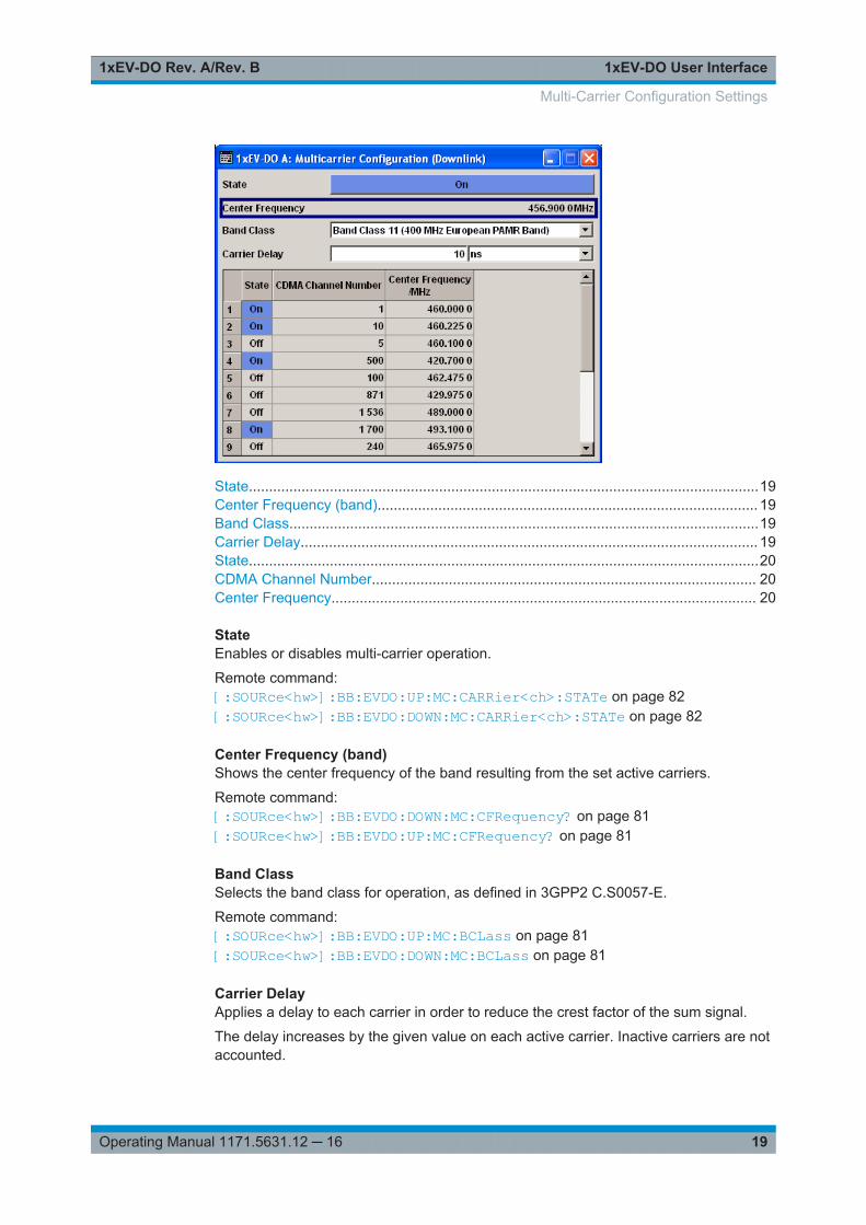
3.3 Multi-Carrier Configuration Settings
Multi-Carrier Configuration requires option R&S SMx/AMU-K87
In multi-carrier mode, up to 16 modulated carriers can be generated with one base-band. Each carrier’s center frequency is input via it’s "CDMA Channel Number" or bydirectly entering the RF "Center Frequency / MHz". The carriers can be activated ordeactivated separately.
Multi-Carrier Configuration Settings
1xEV-DO User Interface1xEV-DO Rev. A/Rev. B
19Operating Manual 1171.5631.12 ─ 16
State..............................................................................................................................19Center Frequency (band).............................................................................................. 19Band Class....................................................................................................................19Carrier Delay................................................................................................................. 19State..............................................................................................................................20CDMA Channel Number............................................................................................... 20Center Frequency......................................................................................................... 20
StateEnables or disables multi-carrier operation.
Remote command: [:SOURce<hw>]:BB:EVDO:UP:MC:CARRier<ch>:STATe on page 82[:SOURce<hw>]:BB:EVDO:DOWN:MC:CARRier<ch>:STATe on page 82
Center Frequency (band)Shows the center frequency of the band resulting from the set active carriers.
Remote command: [:SOURce<hw>]:BB:EVDO:DOWN:MC:CFRequency? on page 81[:SOURce<hw>]:BB:EVDO:UP:MC:CFRequency? on page 81
Band ClassSelects the band class for operation, as defined in 3GPP2 C.S0057-E.
Remote command: [:SOURce<hw>]:BB:EVDO:UP:MC:BCLass on page 81[:SOURce<hw>]:BB:EVDO:DOWN:MC:BCLass on page 81
Carrier DelayApplies a delay to each carrier in order to reduce the crest factor of the sum signal.
The delay increases by the given value on each active carrier. Inactive carriers are notaccounted.
Multi-Carrier Configuration Settings
1xEV-DO User Interface1xEV-DO Rev. A/Rev. B
20Operating Manual 1171.5631.12 ─ 16
Example: "Carrier Delay = 1000 ns"The first active carrier is delayed by 0 ns, the second by 1000 ns, the third by 2000 ns,etc.
Remote command: [:SOURce<hw>]:BB:EVDO:UP:MC:CDELay on page 82[:SOURce<hw>]:BB:EVDO:DOWN:MC:CDELay on page 82
StateSwitches the selected carrier on or off.
Remote command: [:SOURce<hw>]:BB:EVDO:UP:MC:CARRier<ch>:STATe on page 82[:SOURce<hw>]:BB:EVDO:DOWN:MC:CARRier<ch>:STATe on page 82
CDMA Channel NumberSelects the carrier’s channel number.
The selected channel numbers are directly translated into center frequencies, accord-ing to the used band class. In some cases, not all channel numbers in the range that isindicated by the tool tip are allowed. In case a non-existing channel is selected, thesoftware selects the next available channel.
Remote command: [:SOURce<hw>]:BB:EVDO:UP:MC:CARRier<ch>:CHANnel on page 82[:SOURce<hw>]:BB:EVDO:DOWN:MC:CARRier<ch>:CHANnel on page 82
Center FrequencySets the center frequency of the carrier.
In some cases, not all center frequencies in the range that is indicated by the tool tipare defined by the selected band class. In case a non-existing frequency is selected,the software selects the next available frequency.
Remote command: [:SOURce<hw>]:BB:EVDO:UP:MC:CARRier<ch>:FREQuency on page 83[:SOURce<hw>]:BB:EVDO:DOWN:MC:CARRier<ch>:FREQuency on page 83
3.4 Traffic Channel Settings
Access:
1. Select "Baseband > 1xEV-DO > Link Direction > Downlink"
2. Select "Traffic Channels".
Traffic Channel Settings
1xEV-DO User Interface1xEV-DO Rev. A/Rev. B
21Operating Manual 1171.5631.12 ─ 16
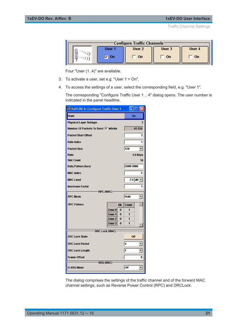
Four "User (1..4)" are available.
3. To activate a user, set e.g. "User 1 > On".
4. To access the settings of a user, select the corresponding field, e.g. "User 1".
The corresponding "Configure Traffic User 1 .. 4" dialog opens. The user number isindicated in the panel headline.
The dialog comprises the settings of the traffic channel and of the forward MACchannel settings, such as Reverse Power Control (RPC) and DRCLock.
Traffic Channel Settings
1xEV-DO User Interface1xEV-DO Rev. A/Rev. B
22Operating Manual 1171.5631.12 ─ 16
State (User)Enables or disables the selected user.
If the user is enabled, the proper "MAC Index" is placed within the MAC channel andpackets can be sent to the user. If disabled, the "MAC Index" is not present within theMAC channel and packets cannot be sent to the user.
Note: Disabling the state of a user during a transfer aborts all transfers to the user.
Remote command: [:SOURce<hw>]:BB:EVDO:USER<st>:STATe on page 92
Physical Layer Subtype (User)Displays the physical layer subtype selected in the menu "Access Network Settings".
Remote command: [:SOURce<hw>]:BB:EVDO:ANETwork:SUBType on page 80
Number of Packets to Send - InfiniteEnables or disables sending an unlimited number of packets to the selected user.
If "Infinite" is enabled, there is no limit to the number of packets sent to the user.
If "Infinite" is disabled, the number of packets to be sent to the selected "User" can bespecified.
Remote command: [:SOURce<hw>]:BB:EVDO:USER<st>:PACKet:INFinite on page 88
Number of Packets to Send - ValueSets the number of packets to send to the selected user.
The number of packets to be sent depends on whether the parameter "Infinite" isenabled or disabled. If "Infinite" is enabled, there is no limit to the number of packetssent to the user.
If "Infinite" is disabled and a value is specified while packets are being sent, the newcount value is used at the end of transmission of the current packet. If a value of zerois specified, the transmission to the user is stopped at the end of the current packet.
Remote command: [:SOURce<hw>]:BB:EVDO:USER<st>:PACKet:INFinite on page 88[:SOURce<hw>]:BB:EVDO:USER<st>:PACKet:COUNt on page 87
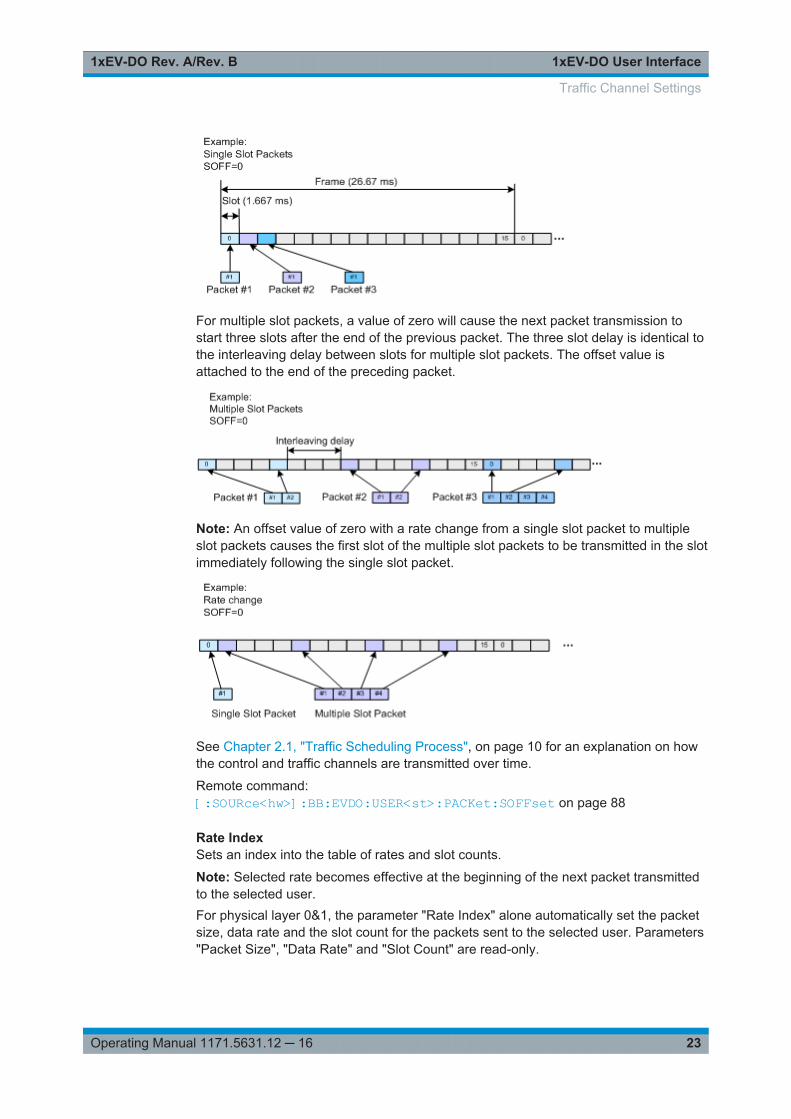
Packet Start OffsetSets the minimum number of slots between the end of one packet and the beginning ofthe next.
For single slot packets, a value of zero will cause the next packet to be sent in theimmediate next slot (subject to scheduling).
Traffic Channel Settings
1xEV-DO User Interface1xEV-DO Rev. A/Rev. B
23Operating Manual 1171.5631.12 ─ 16
For multiple slot packets, a value of zero will cause the next packet transmission tostart three slots after the end of the previous packet. The three slot delay is identical tothe interleaving delay between slots for multiple slot packets. The offset value isattached to the end of the preceding packet.
Note: An offset value of zero with a rate change from a single slot packet to multipleslot packets causes the first slot of the multiple slot packets to be transmitted in the slotimmediately following the single slot packet.
See Chapter 2.1, "Traffic Scheduling Process", on page 10 for an explanation on howthe control and traffic channels are transmitted over time.
Remote command: [:SOURce<hw>]:BB:EVDO:USER<st>:PACKet:SOFFset on page 88
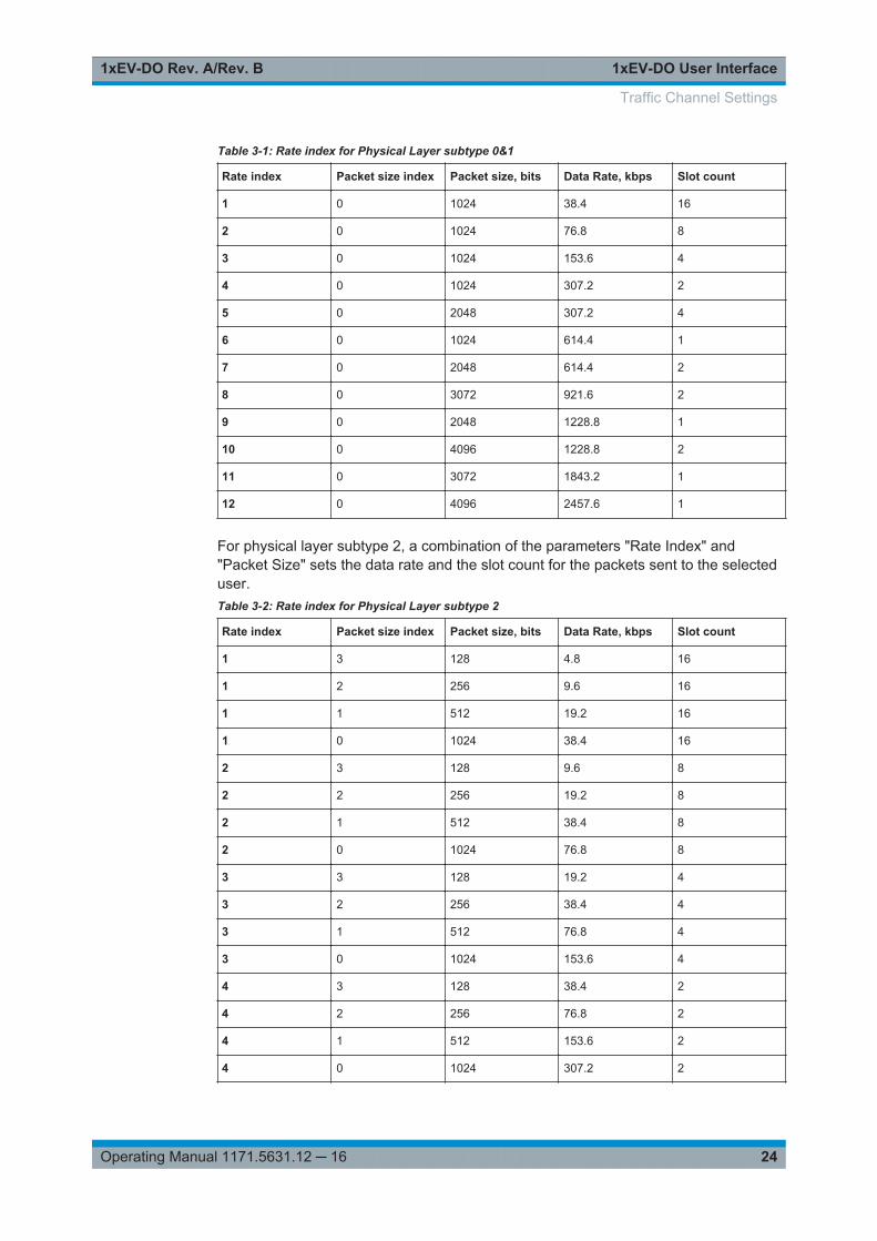
Rate IndexSets an index into the table of rates and slot counts.
Note: Selected rate becomes effective at the beginning of the next packet transmittedto the selected user.For physical layer 0&1, the parameter "Rate Index" alone automatically set the packetsize, data rate and the slot count for the packets sent to the selected user. Parameters"Packet Size", "Data Rate" and "Slot Count" are read-only.
Traffic Channel Settings
1xEV-DO User Interface1xEV-DO Rev. A/Rev. B
24Operating Manual 1171.5631.12 ─ 16
Table 3-1: Rate index for Physical Layer subtype 0&1
Rate index Packet size index Packet size, bits Data Rate, kbps Slot count
1 0 1024 38.4 16
2 0 1024 76.8 8
3 0 1024 153.6 4
4 0 1024 307.2 2
5 0 2048 307.2 4
6 0 1024 614.4 1
7 0 2048 614.4 2
8 0 3072 921.6 2
9 0 2048 1228.8 1
10 0 4096 1228.8 2
11 0 3072 1843.2 1
12 0 4096 2457.6 1
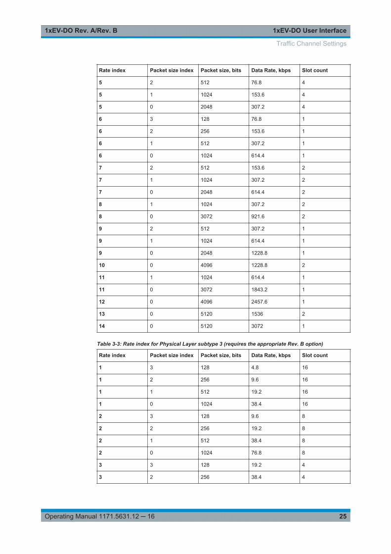
For physical layer subtype 2, a combination of the parameters "Rate Index" and"Packet Size" sets the data rate and the slot count for the packets sent to the selecteduser.Table 3-2: Rate index for Physical Layer subtype 2
Rate index Packet size index Packet size, bits Data Rate, kbps Slot count
1 3 128 4.8 16
1 2 256 9.6 16
1 1 512 19.2 16
1 0 1024 38.4 16
2 3 128 9.6 8
2 2 256 19.2 8
2 1 512 38.4 8
2 0 1024 76.8 8
3 3 128 19.2 4
3 2 256 38.4 4
3 1 512 76.8 4
3 0 1024 153.6 4
4 3 128 38.4 2
4 2 256 76.8 2
4 1 512 153.6 2
4 0 1024 307.2 2
Traffic Channel Settings
1xEV-DO User Interface1xEV-DO Rev. A/Rev. B
25Operating Manual 1171.5631.12 ─ 16
Rate index Packet size index Packet size, bits Data Rate, kbps Slot count
5 2 512 76.8 4
5 1 1024 153.6 4
5 0 2048 307.2 4
6 3 128 76.8 1
6 2 256 153.6 1
6 1 512 307.2 1
6 0 1024 614.4 1
7 2 512 153.6 2
7 1 1024 307.2 2
7 0 2048 614.4 2
8 1 1024 307.2 2
8 0 3072 921.6 2
9 2 512 307.2 1
9 1 1024 614.4 1
9 0 2048 1228.8 1
10 0 4096 1228.8 2
11 1 1024 614.4 1
11 0 3072 1843.2 1
12 0 4096 2457.6 1
13 0 5120 1536 2
14 0 5120 3072 1
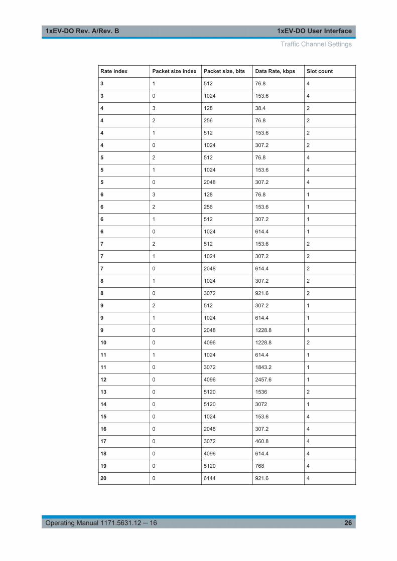
Table 3-3: Rate index for Physical Layer subtype 3 (requires the appropriate Rev. B option)
Rate index Packet size index Packet size, bits Data Rate, kbps Slot count
1 3 128 4.8 16
1 2 256 9.6 16
1 1 512 19.2 16
1 0 1024 38.4 16
2 3 128 9.6 8
2 2 256 19.2 8
2 1 512 38.4 8
2 0 1024 76.8 8
3 3 128 19.2 4
3 2 256 38.4 4
Traffic Channel Settings
1xEV-DO User Interface1xEV-DO Rev. A/Rev. B
26Operating Manual 1171.5631.12 ─ 16
Rate index Packet size index Packet size, bits Data Rate, kbps Slot count
3 1 512 76.8 4
3 0 1024 153.6 4
4 3 128 38.4 2
4 2 256 76.8 2
4 1 512 153.6 2
4 0 1024 307.2 2
5 2 512 76.8 4
5 1 1024 153.6 4
5 0 2048 307.2 4
6 3 128 76.8 1
6 2 256 153.6 1
6 1 512 307.2 1
6 0 1024 614.4 1
7 2 512 153.6 2
7 1 1024 307.2 2
7 0 2048 614.4 2
8 1 1024 307.2 2
8 0 3072 921.6 2
9 2 512 307.2 1
9 1 1024 614.4 1
9 0 2048 1228.8 1
10 0 4096 1228.8 2
11 1 1024 614.4 1
11 0 3072 1843.2 1
12 0 4096 2457.6 1
13 0 5120 1536 2
14 0 5120 3072 1
15 0 1024 153.6 4
16 0 2048 307.2 4
17 0 3072 460.8 4
18 0 4096 614.4 4
19 0 5120 768 4
20 0 6144 921.6 4
Traffic Channel Settings
1xEV-DO User Interface1xEV-DO Rev. A/Rev. B
27Operating Manual 1171.5631.12 ─ 16
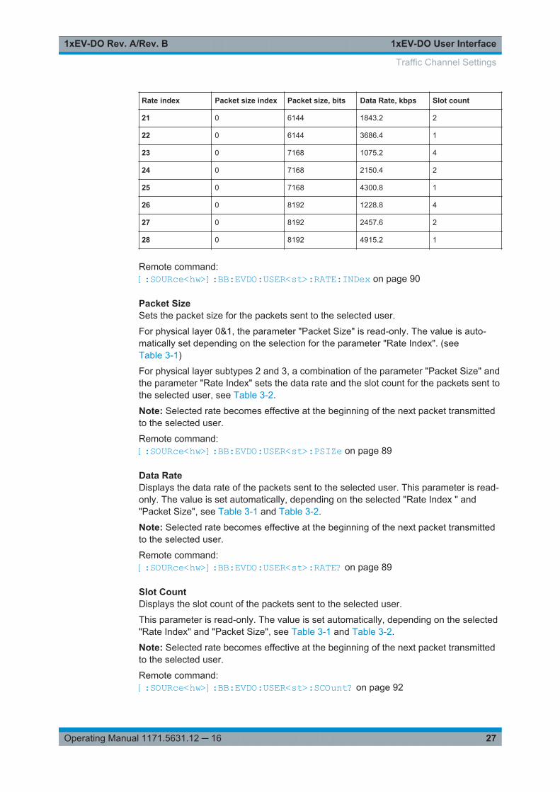
Rate index Packet size index Packet size, bits Data Rate, kbps Slot count
21 0 6144 1843.2 2
22 0 6144 3686.4 1
23 0 7168 1075.2 4
24 0 7168 2150.4 2
25 0 7168 4300.8 1
26 0 8192 1228.8 4
27 0 8192 2457.6 2
28 0 8192 4915.2 1
Remote command: [:SOURce<hw>]:BB:EVDO:USER<st>:RATE:INDex on page 90
Packet SizeSets the packet size for the packets sent to the selected user.
For physical layer 0&1, the parameter "Packet Size" is read-only. The value is auto-matically set depending on the selection for the parameter "Rate Index". (seeTable 3-1)
For physical layer subtypes 2 and 3, a combination of the parameter "Packet Size" andthe parameter "Rate Index" sets the data rate and the slot count for the packets sent tothe selected user, see Table 3-2.
Note: Selected rate becomes effective at the beginning of the next packet transmittedto the selected user.
Remote command: [:SOURce<hw>]:BB:EVDO:USER<st>:PSIZe on page 89
Data RateDisplays the data rate of the packets sent to the selected user. This parameter is read-only. The value is set automatically, depending on the selected "Rate Index " and"Packet Size", see Table 3-1 and Table 3-2.
Note: Selected rate becomes effective at the beginning of the next packet transmittedto the selected user.
Remote command: [:SOURce<hw>]:BB:EVDO:USER<st>:RATE? on page 89
Slot CountDisplays the slot count of the packets sent to the selected user.
This parameter is read-only. The value is set automatically, depending on the selected"Rate Index" and "Packet Size", see Table 3-1 and Table 3-2.
Note: Selected rate becomes effective at the beginning of the next packet transmittedto the selected user.
Remote command: [:SOURce<hw>]:BB:EVDO:USER<st>:SCOunt? on page 92
Traffic Channel Settings
1xEV-DO User Interface1xEV-DO Rev. A/Rev. B
28Operating Manual 1171.5631.12 ─ 16
Data Pattern (hex)Sets the data pattern for the data portion of the packets sent to the user.
The most significant bit (MSB) of this value is the MSB of the packet and the word isrepeated to fill all space within the packet. This parameter is in a hexadecimal format.
Remote command: [:SOURce<hw>]:BB:EVDO:USER<st>:DATA:PATTern on page 84
MAC IndexSets the MAC index used for the selected user.
MAC indexes have to be different for the different users. However, in case that twousers are using the same value for MAC index, the lower priority user is disabled, or beunable to enable.
The values for the MAC indexes for the other users (see parameter Other UsersCount) are assigned from a pool of valid MAC indexes, that exclude the MAC indexesspecified for each of the four configurable users.
Remote command: [:SOURce<hw>]:BB:EVDO:USER<st>:MAC:INDex on page 86
MAC LevelSets the power within the MAC channel that is dedicated to the selected user.
Remote command: [:SOURce<hw>]:BB:EVDO:USER<st>:MAC:LEVel on page 87
Interleave FactorControls the number of interleave slots used for the selected user on the forward link.
Four interleave slots are defined in the 1xEV-DO system. By default, only 1 interleaveslot ("Interleave Factor" = 1) for an access terminal is configured and transmission tothat access terminal every fourth slot is selected. For an interleave factor > 1, packetson multiple interleave slots are sent, increasing the data throughput to the access ter-minal.
Remote command: [:SOURce<hw>]:BB:EVDO:USER<st>:IFACtor on page 86
RPC ModeSets the operation mode for the Reverse Power Control (RPC) Channel within theMAC channel for the selected user.
"Hold" An alternating series of up and down power control bits are transmit-ted. The intent is to hold the access terminal at a constant powerlevel. This mode always starts with an up bit, and ends with the fol-lowing down bit. This mode is 2 bits long.
"All up" A continuous stream of up (0) power control bits are transmitted. Theintent is to force the access terminal to the highest transmit powerlevel.This mode is a single bit long.
Traffic Channel Settings
1xEV-DO User Interface1xEV-DO Rev. A/Rev. B
29Operating Manual 1171.5631.12 ─ 16
"All down" A continuous stream of down (1) power control bits are transmitted.The intent is to force the access terminal to the lowest transmit powerlevel.This mode is a single bit long.
"Range" A sequence of up power control bits is sent followed by an equalnumber of down power control bits. The intent is to force the accessterminal to ramp its power from one extreme to another. The numberof power control bits in each direction is specified by the "RPC RangeCount" parameter. (see RPC Range Count). Each time that the rangemode is specified, the sequence is restarted.The range mode starts with the first up bit and ends with the lastdown bit.The length of the mode is two times the RPC range Count.
"Pattern" A user-defined sequence of RPC bits is sent. The mode starts withthe bit defined in the first (0) zone, and ends with the last bit of thelast (3) zone. The length of the pattern is the sum of the Count valuesfor each RPC zone.
Remote command: [:SOURce<hw>]:BB:EVDO:USER<st>:RPC:MODE on page 91
RPC Range CountSets the number of Reverse Power Control (RPC) bits sent in each direction when the"RPC Mode" is set to "Range". The specified value is used immediately.
Note: This parameter is displayed in RPC mode "Range" only.
Remote command: [:SOURce<hw>]:BB:EVDO:USER<st>:RPC:RANGe on page 91
RPC PatternDefines the Reverse Power Control (RPC) pattern in form of table with four zones(zone 0 .. 3).
For each zone, a bit and a count can be defined.
"Bit" Defines the RPC bits sent within the specific zone of the RPC pattern.
"Count" Defines the number of RPC bits sent within the specific zone of theRPC pattern.
Remote command: [:SOURce<hw>]:BB:EVDO:USER<st>:RPC:ZONE<ch0>:BIT on page 91[:SOURce<hw>]:BB:EVDO:USER<st>:RPC:ZONE<ch0>:COUNt on page 92
DRC Lock StateSets the state of the DRC (Data Rate Control) lock bit for the selected user.
Note: Changes in the DRC lock state are only considered at the interval defined by theparameter DRC lock length.
Remote command: [:SOURce<hw>]:BB:EVDO:USER<st>:DRCLock:STATe on page 85
Traffic Channel Settings
1xEV-DO User Interface1xEV-DO Rev. A/Rev. B
30Operating Manual 1171.5631.12 ─ 16
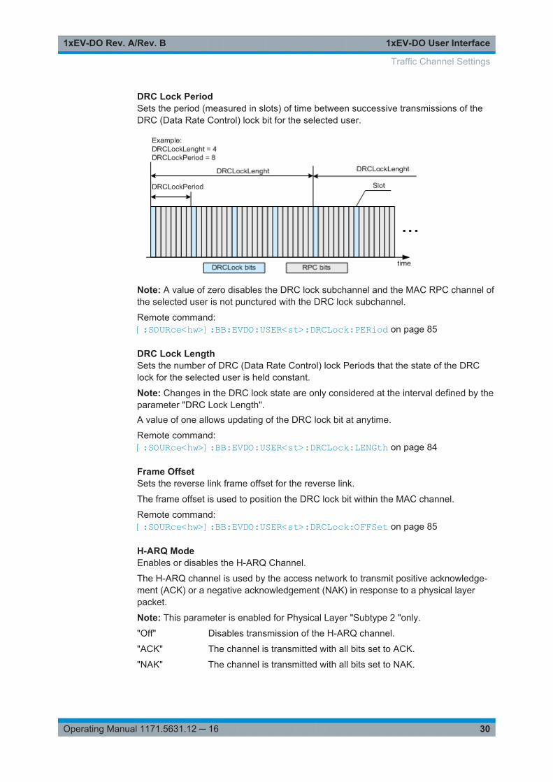
DRC Lock PeriodSets the period (measured in slots) of time between successive transmissions of theDRC (Data Rate Control) lock bit for the selected user.
Note: A value of zero disables the DRC lock subchannel and the MAC RPC channel ofthe selected user is not punctured with the DRC lock subchannel.
Remote command: [:SOURce<hw>]:BB:EVDO:USER<st>:DRCLock:PERiod on page 85
DRC Lock LengthSets the number of DRC (Data Rate Control) lock Periods that the state of the DRClock for the selected user is held constant.
Note: Changes in the DRC lock state are only considered at the interval defined by theparameter "DRC Lock Length".A value of one allows updating of the DRC lock bit at anytime.
Remote command: [:SOURce<hw>]:BB:EVDO:USER<st>:DRCLock:LENGth on page 84
Frame OffsetSets the reverse link frame offset for the reverse link.
The frame offset is used to position the DRC lock bit within the MAC channel.
Remote command: [:SOURce<hw>]:BB:EVDO:USER<st>:DRCLock:OFFSet on page 85
H-ARQ ModeEnables or disables the H-ARQ Channel.
The H-ARQ channel is used by the access network to transmit positive acknowledge-ment (ACK) or a negative acknowledgement (NAK) in response to a physical layerpacket.
Note: This parameter is enabled for Physical Layer "Subtype 2 "only.
"Off" Disables transmission of the H-ARQ channel.
"ACK" The channel is transmitted with all bits set to ACK.
"NAK" The channel is transmitted with all bits set to NAK.
Traffic Channel Settings
1xEV-DO User Interface1xEV-DO Rev. A/Rev. B
31Operating Manual 1171.5631.12 ─ 16
Remote command: [:SOURce<hw>]:BB:EVDO:USER<st>:HARQ:MODE on page 85
3.5 Access Terminal Settings
Access:
1. Select "Baseband > 1xEV-DO > Link Direction > Uplink"
2. Select "Access Terminals".
Four terminals are available.
3. To enable a subset of predefined settings for faster configuration, select "Prede-fined Settings".
4. To activate a terminal, set its state to "On", e.g. "Terminal 1 > On".
5. To access the settings of a terminal, select the corresponding field, e.g. "Terminal1".
The corresponding "Configure Access Terminal 1 .. 4" dialog opens. The accessterminal number is indicated in the panel headline.
Access Terminal Settings
1xEV-DO User Interface1xEV-DO Rev. A/Rev. B
32Operating Manual 1171.5631.12 ─ 16
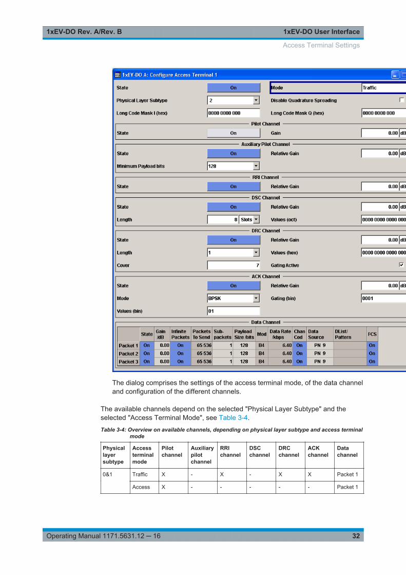
The dialog comprises the settings of the access terminal mode, of the data channeland configuration of the different channels.
The available channels depend on the selected "Physical Layer Subtype" and theselected "Access Terminal Mode", see Table 3-4.
Table 3-4: Overview on available channels, depending on physical layer subtype and access terminalmode
Physicallayersubtype
Accessterminalmode
Pilotchannel
Auxiliarypilotchannel
RRIchannel
DSCchannel
DRCchannel
ACKchannel
Datachannel
0&1 Traffic X - X - X X Packet 1
Access X - - - - - Packet 1
Access Terminal Settings
1xEV-DO User Interface1xEV-DO Rev. A/Rev. B
33Operating Manual 1171.5631.12 ─ 16
Physicallayersubtype
Accessterminalmode
Pilotchannel
Auxiliarypilotchannel
RRIchannel
DSCchannel
DRCchannel
ACKchannel
Datachannel
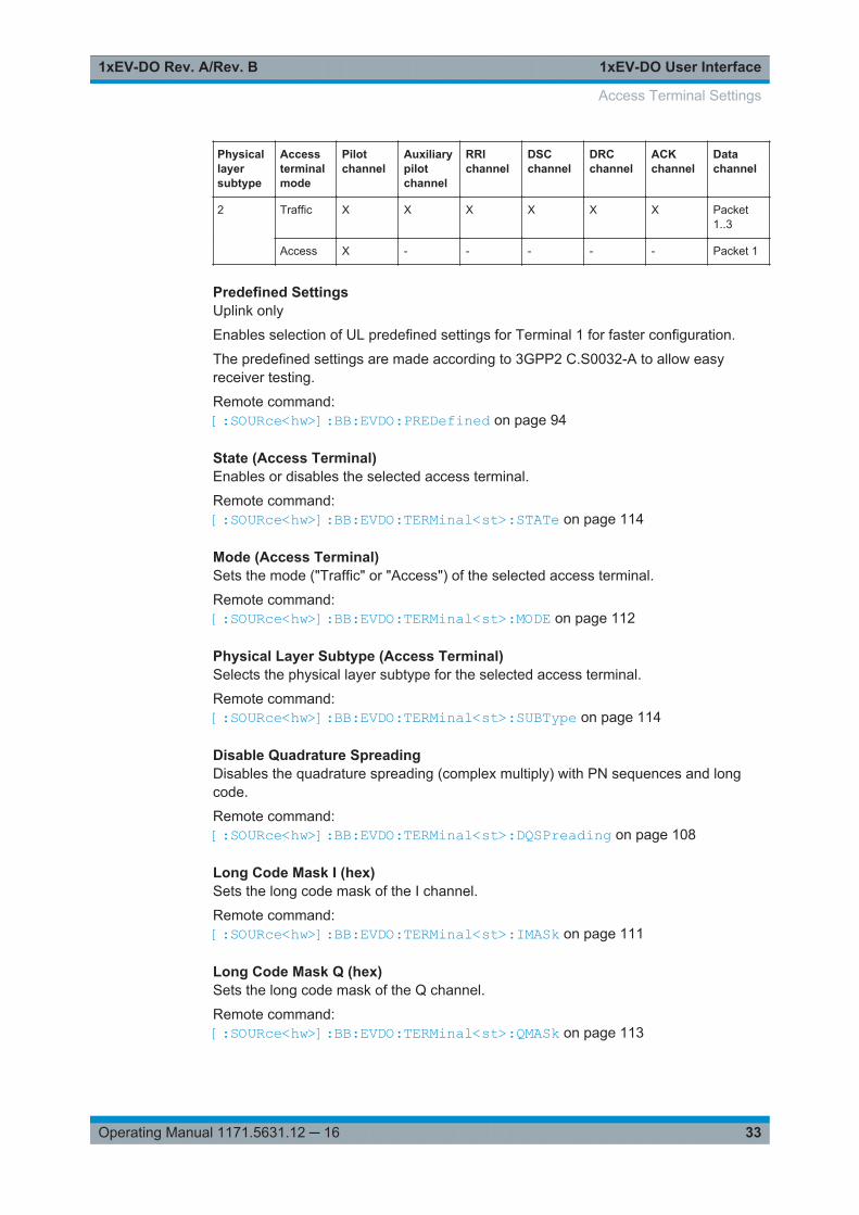
2 Traffic X X X X X X Packet1..3
Access X - - - - - Packet 1
Predefined SettingsUplink only
Enables selection of UL predefined settings for Terminal 1 for faster configuration.
The predefined settings are made according to 3GPP2 C.S0032-A to allow easyreceiver testing.
Remote command: [:SOURce<hw>]:BB:EVDO:PREDefined on page 94
State (Access Terminal)Enables or disables the selected access terminal.
Remote command: [:SOURce<hw>]:BB:EVDO:TERMinal<st>:STATe on page 114
Mode (Access Terminal)Sets the mode ("Traffic" or "Access") of the selected access terminal.
Remote command: [:SOURce<hw>]:BB:EVDO:TERMinal<st>:MODE on page 112
Physical Layer Subtype (Access Terminal)Selects the physical layer subtype for the selected access terminal.
Remote command: [:SOURce<hw>]:BB:EVDO:TERMinal<st>:SUBType on page 114
Disable Quadrature SpreadingDisables the quadrature spreading (complex multiply) with PN sequences and longcode.
Remote command: [:SOURce<hw>]:BB:EVDO:TERMinal<st>:DQSPreading on page 108
Long Code Mask I (hex)Sets the long code mask of the I channel.
Remote command: [:SOURce<hw>]:BB:EVDO:TERMinal<st>:IMASk on page 111
Long Code Mask Q (hex)Sets the long code mask of the Q channel.
Remote command: [:SOURce<hw>]:BB:EVDO:TERMinal<st>:QMASk on page 113
Access Terminal Settings
1xEV-DO User Interface1xEV-DO Rev. A/Rev. B
34Operating Manual 1171.5631.12 ─ 16
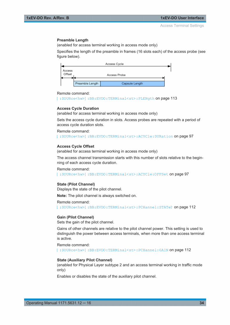
Preamble Length(enabled for access terminal working in access mode only)
Specifies the length of the preamble in frames (16 slots each) of the access probe (seefigure below).
Remote command: [:SOURce<hw>]:BB:EVDO:TERMinal<st>:PLENgth on page 113
Access Cycle Duration(enabled for access terminal working in access mode only)
Sets the access cycle duration in slots. Access probes are repeated with a period ofaccess cycle duration slots.
Remote command: [:SOURce<hw>]:BB:EVDO:TERMinal<st>:ACYCle:DURation on page 97
Access Cycle Offset(enabled for access terminal working in access mode only)
The access channel transmission starts with this number of slots relative to the begin-ning of each access cycle duration.
Remote command: [:SOURce<hw>]:BB:EVDO:TERMinal<st>:ACYCle:OFFSet on page 97
State (Pilot Channel)Displays the state of the pilot channel.
Note: The pilot channel is always switched on.
Remote command: [:SOURce<hw>]:BB:EVDO:TERMinal<st>:PCHannel:STATe? on page 112
Gain (Pilot Channel)Sets the gain of the pilot channel.
Gains of other channels are relative to the pilot channel power. This setting is used todistinguish the power between access terminals, when more than one access terminalis active.
Remote command: [:SOURce<hw>]:BB:EVDO:TERMinal<st>:PCHannel:GAIN on page 112
State (Auxiliary Pilot Channel)(enabled for Physical Layer subtype 2 and an access terminal working in traffic modeonly)
Enables or disables the state of the auxiliary pilot channel.
Access Terminal Settings
1xEV-DO User Interface1xEV-DO Rev. A/Rev. B
35Operating Manual 1171.5631.12 ─ 16
Remote command: [:SOURce<hw>]:BB:EVDO:TERMinal<st>:APCHannel:STATe on page 98
Relative Gain (Auxiliary Pilot Channel)Sets the gain of the auxiliary pilot channel relative to the data channel power.
Note: All other channel gains are specified relative to the pilot channel power, but theauxiliary pilot gain is specified relative to the data channel power. This parameter isonly enabled for Physical Layer subtype 2 and for an access terminal working in trafficmode.
Remote command: [:SOURce<hw>]:BB:EVDO:TERMinal<st>:APCHannel:GAIN on page 98
Minimum Payload (Auxiliary Pilot Channel)(enabled for Physical Layer subtype 2 and an access terminal working in traffic modeonly)
Sets the minimum payload size in bits of the data channel that activates the transmis-sion of the auxiliary pilot channel.
Remote command: [:SOURce<hw>]:BB:EVDO:TERMinal<st>:APCHannel:PAYLoad:MINimumon page 98
State (RRI Channel)(enabled for access terminal working in traffic mode only)
Enables or disables the state of the reverse rate indicator (RRI) channel.
Remote command: [:SOURce<hw>]:BB:EVDO:TERMinal<st>:RRIChannel:STATe on page 113
Relative Gain (RRI Channel)(enabled for access terminal working in traffic mode only)
Sets the gain of the reverse rate indicator (RRI) channel relative to the pilot channelpower.
Remote command: [:SOURce<hw>]:BB:EVDO:TERMinal<st>:RRIChannel:GAIN on page 113
State (DSC Channel)(enabled for Physical Layer subtype 2 and an access terminal working in traffic modeonly)
Enables or disables the state of the data source control (DSC) channel.
Remote command: [:SOURce<hw>]:BB:EVDO:TERMinal<st>:DSCChannel:STATe on page 111
Relative Gain (DSC Channel)(enabled for Physical Layer subtype 2 and an access terminal working in traffic modeonly)
Sets the gain of the data source control (DSC) channel relative to the pilot channelpower.
Access Terminal Settings
1xEV-DO User Interface1xEV-DO Rev. A/Rev. B
36Operating Manual 1171.5631.12 ─ 16
Remote command: [:SOURce<hw>]:BB:EVDO:TERMinal<st>:DSCChannel:GAIN on page 110
Length (DSC Channel)(enabled for Physical Layer subtype 2 and an access terminal working in traffic modeonly)
Specifies the transmission duration of the data source control (DSC) channel in slots.
Remote command: [:SOURce<hw>]:BB:EVDO:TERMinal<st>:DSCChannel:LENGth on page 110
Values (OCT) (DSC Channel)(enabled for Physical Layer subtype 2 and an access terminal working in traffic modeonly)
Specifies the pattern transmitted on the data source control (DSC) Channel.
The sequence starts at frame 0 and slot 0 and is repeated with the length of the pat-tern. Each specified value is transmitted for DSC length slots.
Remote command: [:SOURce<hw>]:BB:EVDO:TERMinal<st>:DSCChannel:VALues on page 111
State (DRC Channel)(enabled for access terminal working in traffic mode only)
Enables or disables the state of the data rate control (DRC) channel.
Remote command: [:SOURce<hw>]:BB:EVDO:TERMinal<st>:DRCChannel:STATe on page 109
Relative Gain (DRC Channel)(enabled for access terminal working in traffic mode only)
Sets the gain of the data rate control (DRC) channel relative to the pilot channel power.
Remote command: [:SOURce<hw>]:BB:EVDO:TERMinal<st>:DRCChannel:GAIN on page 108
Length (DRC Channel)(enabled for access terminal working in traffic mode only)
Specifies the transmission duration of the data rate control (DRC) channel in slots.
Remote command: [:SOURce<hw>]:BB:EVDO:TERMinal<st>:DRCChannel:LENGth on page 109
Values (hex) (DRC Channel)(enabled for access terminal working in traffic mode only)
Specifies the pattern transmitted on the data rate control (DRC) channel.
The sequence starts at frame 0 and slot 0 and is repeated with the length of the pat-tern. Each specified value is used for DRC length slots.
Remote command: [:SOURce<hw>]:BB:EVDO:TERMinal<st>:DRCChannel:VALues on page 110
Access Terminal Settings
1xEV-DO User Interface1xEV-DO Rev. A/Rev. B
37Operating Manual 1171.5631.12 ─ 16
Cover (DRC Channel)(enabled for access terminal working in traffic mode only)
Selects the data rate control (DRC) channel Walsh cover.
Remote command: [:SOURce<hw>]:BB:EVDO:TERMinal<st>:DRCChannel:COVer on page 108
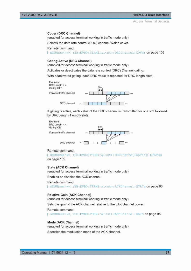
Gating Active (DRC Channel)(enabled for access terminal working in traffic mode only)
Activates or deactivates the data rate control (DRC) Channel gating.
With deactivated gating, each DRC value is repeated for DRC length slots.
If gating is active, each value of the DRC channel is transmitted for one slot followedby DRCLenght-1 empty slots.
Remote command: [:SOURce<hw>]:BB:EVDO:TERMinal<st>:DRCChannel:GATing[:STATe]on page 109
State (ACK Channel)(enabled for access terminal working in traffic mode only)
Enables or disables the ACK channel.
Remote command: [:SOURce<hw>]:BB:EVDO:TERMinal<st>:ACKChannel:STATe on page 96
Relative Gain (ACK Channel)(enabled for access terminal working in traffic mode only)
Sets the gain of the ACK channel relative to the pilot channel power.
Remote command: [:SOURce<hw>]:BB:EVDO:TERMinal<st>:ACKChannel:GAIN on page 95
Mode (ACK Channel)(enabled for access terminal working in traffic mode only)
Specifies the modulation mode of the ACK channel.
Access Terminal Settings
1xEV-DO User Interface1xEV-DO Rev. A/Rev. B
38Operating Manual 1171.5631.12 ─ 16
"BPSK" Sets the modulation to BPSK (Binary Phase Shift Keying).With BPSK modulation, a 0 (ACK) is mapped to +1 and a 1 (NAK) to-1 respectively.
"OOK" Sets the modulation to OOK (On/Off keying). With OOK modulation, a0 (ACK) is mapped to ON and a 1 (NAK) to OFF.
Note: OKK modulation is only enabled for physical layer subtype 2.
Remote command: [:SOURce<hw>]:BB:EVDO:TERMinal<st>:ACKChannel:MODE on page 96
Gating (bin) (ACK Channel)(enabled for access terminal working in traffic mode only)
Sets the active and inactive slots of the ACK channel.
The sequence starts at frame 0 and slot 0 and is repeated with the length of the pat-tern.
A 0 gates the ACK channel off for the corresponding slot, a 1 activates the channel.
Remote command: [:SOURce<hw>]:BB:EVDO:TERMinal<st>:ACKChannel:GATing on page 95
Values (ACK Channel)(enabled for access terminal working in traffic mode only)
Specifies the data pattern transmitted on the ACK Channel.
The sequence starts at frame 0 and slot 0 and is repeated with the length of the pat-tern. A 0 specifies an ACK, a 1 specifies a NAK. This pattern is only read for slots thatare gated on.
Remote command: [:SOURce<hw>]:BB:EVDO:TERMinal<st>:ACKChannel:VALues on page 97
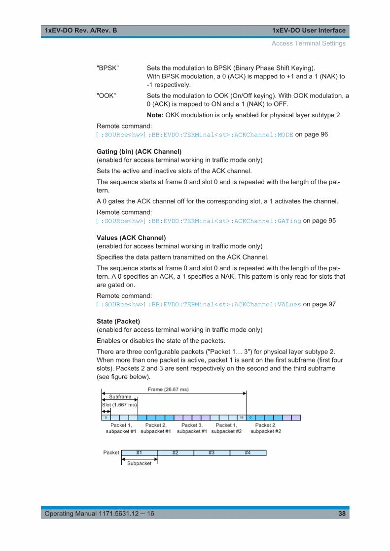
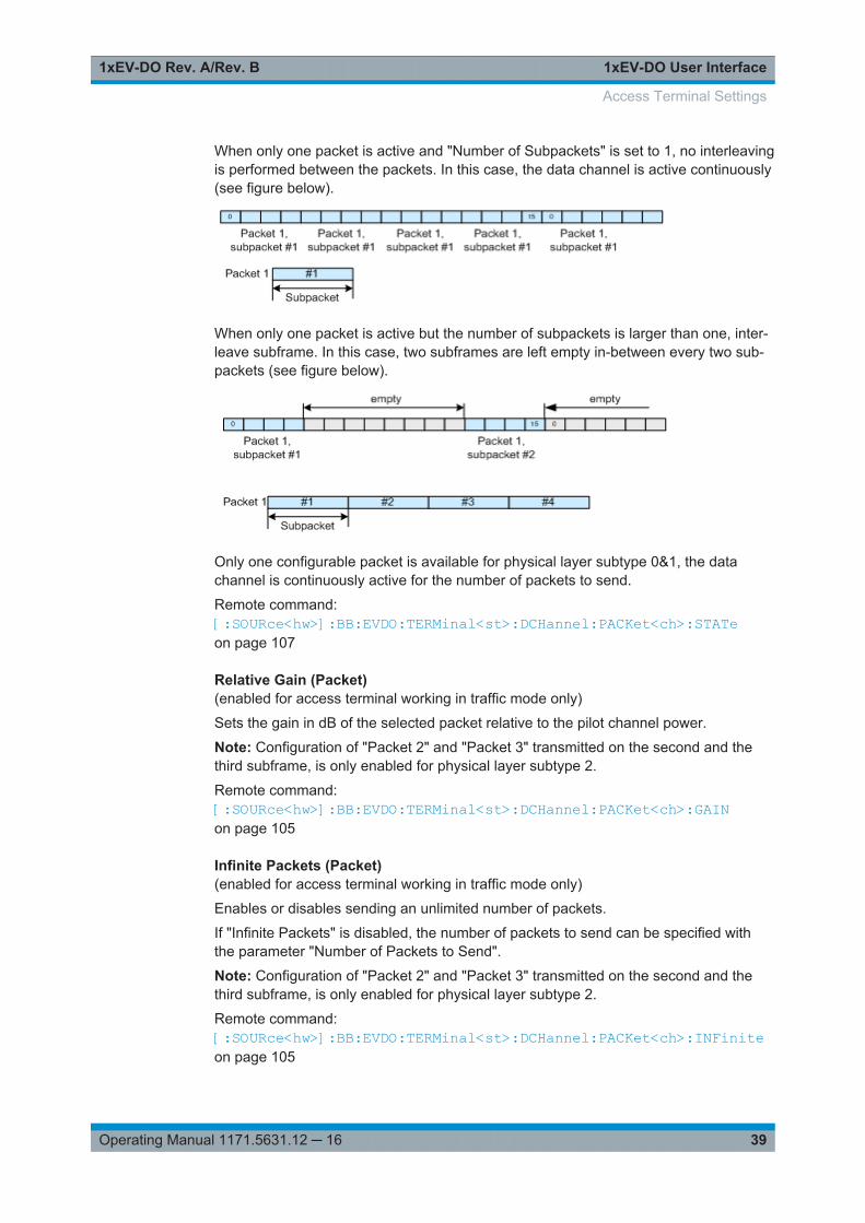
State (Packet)(enabled for access terminal working in traffic mode only)
Enables or disables the state of the packets.
There are three configurable packets ("Packet 1… 3") for physical layer subtype 2.When more than one packet is active, packet 1 is sent on the first subframe (first fourslots). Packets 2 and 3 are sent respectively on the second and the third subframe(see figure below).
Access Terminal Settings
1xEV-DO User Interface1xEV-DO Rev. A/Rev. B
39Operating Manual 1171.5631.12 ─ 16
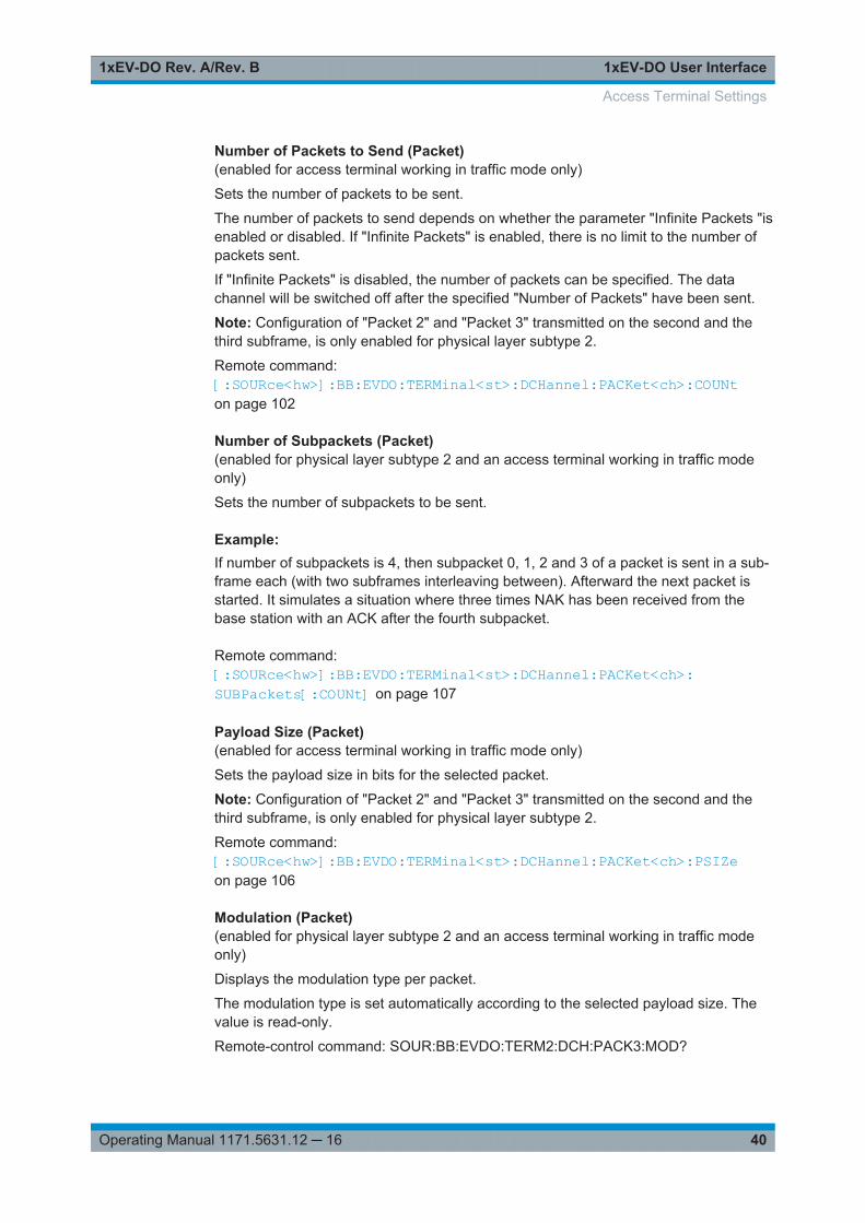
When only one packet is active and "Number of Subpackets" is set to 1, no interleavingis performed between the packets. In this case, the data channel is active continuously(see figure below).
When only one packet is active but the number of subpackets is larger than one, inter-leave subframe. In this case, two subframes are left empty in-between every two sub-packets (see figure below).
Only one configurable packet is available for physical layer subtype 0&1, the datachannel is continuously active for the number of packets to send.
Remote command: [:SOURce<hw>]:BB:EVDO:TERMinal<st>:DCHannel:PACKet<ch>:STATeon page 107
Relative Gain (Packet)(enabled for access terminal working in traffic mode only)
Sets the gain in dB of the selected packet relative to the pilot channel power.
Note: Configuration of "Packet 2" and "Packet 3" transmitted on the second and thethird subframe, is only enabled for physical layer subtype 2.
Remote command: [:SOURce<hw>]:BB:EVDO:TERMinal<st>:DCHannel:PACKet<ch>:GAINon page 105
Infinite Packets (Packet)(enabled for access terminal working in traffic mode only)
Enables or disables sending an unlimited number of packets.
If "Infinite Packets" is disabled, the number of packets to send can be specified withthe parameter "Number of Packets to Send".
Note: Configuration of "Packet 2" and "Packet 3" transmitted on the second and thethird subframe, is only enabled for physical layer subtype 2.
Remote command: [:SOURce<hw>]:BB:EVDO:TERMinal<st>:DCHannel:PACKet<ch>:INFiniteon page 105
Access Terminal Settings
1xEV-DO User Interface1xEV-DO Rev. A/Rev. B
40Operating Manual 1171.5631.12 ─ 16
Number of Packets to Send (Packet)(enabled for access terminal working in traffic mode only)
Sets the number of packets to be sent.
The number of packets to send depends on whether the parameter "Infinite Packets "isenabled or disabled. If "Infinite Packets" is enabled, there is no limit to the number ofpackets sent.
If "Infinite Packets" is disabled, the number of packets can be specified. The datachannel will be switched off after the specified "Number of Packets" have been sent.
Note: Configuration of "Packet 2" and "Packet 3" transmitted on the second and thethird subframe, is only enabled for physical layer subtype 2.
Remote command: [:SOURce<hw>]:BB:EVDO:TERMinal<st>:DCHannel:PACKet<ch>:COUNton page 102
Number of Subpackets (Packet)(enabled for physical layer subtype 2 and an access terminal working in traffic modeonly)
Sets the number of subpackets to be sent.
Example: If number of subpackets is 4, then subpacket 0, 1, 2 and 3 of a packet is sent in a sub-frame each (with two subframes interleaving between). Afterward the next packet isstarted. It simulates a situation where three times NAK has been received from thebase station with an ACK after the fourth subpacket.
Remote command: [:SOURce<hw>]:BB:EVDO:TERMinal<st>:DCHannel:PACKet<ch>:SUBPackets[:COUNt] on page 107
Payload Size (Packet)(enabled for access terminal working in traffic mode only)
Sets the payload size in bits for the selected packet.
Note: Configuration of "Packet 2" and "Packet 3" transmitted on the second and thethird subframe, is only enabled for physical layer subtype 2.
Remote command: [:SOURce<hw>]:BB:EVDO:TERMinal<st>:DCHannel:PACKet<ch>:PSIZeon page 106
Modulation (Packet)(enabled for physical layer subtype 2 and an access terminal working in traffic modeonly)
Displays the modulation type per packet.
The modulation type is set automatically according to the selected payload size. Thevalue is read-only.
Remote-control command: SOUR:BB:EVDO:TERM2:DCH:PACK3:MOD?
Access Terminal Settings
1xEV-DO User Interface1xEV-DO Rev. A/Rev. B
41Operating Manual 1171.5631.12 ─ 16
"B4" The modulation type is set to BPSK modulation with 4-ary Walshcover.
"Q4" The modulation type is set to QPSK modulation with 4-ary Walshcover.
"Q2" The modulation type is set to QPSK modulation with 2-ary Walshcover.
"Q4Q2" Sum of Q4 and Q2 modulated symbols.
"E4E2" Sum of E4 (8-PSK modulated with 4-ary Walsh cover) and E2 (8-PSKmodulated with 2-ary Walsh cover) modulated symbols.
Remote command: [:SOURce<hw>]:BB:EVDO:TERMinal<st>:DCHannel:PACKet<ch>:MODulation? on page 106
Data Rate (Packet)(enabled for access terminal working in traffic mode only)
Displays the resulting data rate for the selected packet.
The data rate is the effective data rate achieved for the specific packet. Sum up thedata rates of all three packets to obtain the total effective data rate for the uplink datachannel.
Remote command: [:SOURce<hw>]:BB:EVDO:TERMinal<st>:DCHannel:PACKet<ch>:DRATe?on page 104
Channel Coding (Packet)(enabled for access terminal working in traffic mode only)
Activates or deactivates channel coding, including scrambling, turbo encoding andchannel interleaving.
Note: Configuration of "Packet 2" and "Packet 3" transmitted on the second and thethird subframe, is only enabled for physical layer subtype 2.
Remote command: [:SOURce<hw>]:BB:EVDO:TERMinal<st>:DCHannel:PACKet<ch>:CCODingon page 101
Data Source (Packet)(enabled for access terminal working in traffic mode only)
Selects the data source.
The number of bits read from the data source for each packet depends on the payloadsize, channel coding state and FCS state. The following table gives an overview on thenumber of bits read.
FCS ON FCS OFF
Channel Coding ON PayloadSize - FCSSize - 6 PayloadSize - 6
Channel Coding OFF (PayloadSize/CodeRate) -FCSSize
(PayloadSize/CodeRate)
Access Terminal Settings

1xEV-DO User Interface1xEV-DO Rev. A/Rev. B
42Operating Manual 1171.5631.12 ─ 16
FCSSize and code rate depend on the physical layer subtype (see that table bellow).
Physical layer subtype 0&1 Physical layer subtype 2
FCSSize 16 24
Code rate 1/4 or 1/2 1/5 or 1/3
Note: Configuration of "Packet 2" and "Packet 3" transmitted on the second and thethird subframe, is only enabled for physical layer subtype 2.The following standard data sources are available:● "All 0, All 1"
An internally generated sequence containing 0 data or 1 data.● "PNxx"
An internally generated pseudo-random noise sequence.● "Pattern"
An internally generated sequence according to a bit pattern.Use the "Pattern" box to define the bit pattern.
● "Data List/Select DList"A binary data from a data list, internally or externally generated.Select "Select DList" to access the standard "Select List" dialog.– Select the "Select Data List > navigate to the list file *.dm_iqd > Select" to
select an existing data list.– Use the "New" and "Edit" functions to create internally new data list or to edit
an existing one.– Use the standard "File Manager" function to transfer external data lists to the
instrument.See also "Main Dialog > Data List Management".
Remote command: [:SOURce<hw>]:BB:EVDO:TERMinal<st>:DCHannel:PACKet<ch>:DATAon page 102[:SOURce<hw>]:BB:EVDO:TERMinal<st>:DCHannel:PACKet<ch>:DATA:DSELection on page 103[:SOURce<hw>]:BB:EVDO:TERMinal<st>:DCHannel:PACKet<ch>:DATA:PATTern on page 103
FCS (Packet)(enabled for access terminal working in traffic mode only)
Enables or disables appending a standard frame check sequence (FCS) to the MAClayer packet.
Note: Configuration of "Packet 2" and "Packet 3" transmitted on the second and thethird subframe, is only enabled for physical layer subtype 2.
Remote command: [:SOURce<hw>]:BB:EVDO:TERMinal<st>:DCHannel:PACKet<ch>:FCS[:STATe] on page 104
State (Data Channel)(enabled for access terminal working in access mode only)
Enables or disables the state of the data channel.
Access Terminal Settings
1xEV-DO User Interface1xEV-DO Rev. A/Rev. B
43Operating Manual 1171.5631.12 ─ 16
Remote command: [:SOURce<hw>]:BB:EVDO:TERMinal<st>:DCHannel:STATe on page 107
Relative Gain (Data Channel)(enabled for access terminal working in access mode only)
Sets the gain in dB of the data channel relative to the pilot channel power.
Remote command: [:SOURce<hw>]:BB:EVDO:TERMinal<st>:DCHannel:GAIN on page 101
Capsule Length (Data Channel)(enabled for access terminal working in access mode only)
Sets the number of frames (16 slots each) to be transmitted after the preamble. Eachframe contains one data packet.
Remote command: [:SOURce<hw>]:BB:EVDO:TERMinal<st>:DCHannel:CLENgth on page 99
Data Rate (Data Channel)(enabled for access terminal working in access mode only)
Selects the data rate for the data channel.
Remote command: [:SOURce<hw>]:BB:EVDO:TERMinal<st>:DCHannel:DRATe on page 100
Data Source (Data Channel)(enabled for access terminal working in access mode only)
Selects the data source.
The following standard data sources are available:● "All 0, All 1"
An internally generated sequence containing 0 data or 1 data.● "PNxx"
An internally generated pseudo-random noise sequence.● "Pattern"
An internally generated sequence according to a bit pattern.Use the "Pattern" box to define the bit pattern.
● "Data List/Select DList"A binary data from a data list, internally or externally generated.Select "Select DList" to access the standard "Select List" dialog.– Select the "Select Data List > navigate to the list file *.dm_iqd > Select" to
select an existing data list.– Use the "New" and "Edit" functions to create internally new data list or to edit
an existing one.– Use the standard "File Manager" function to transfer external data lists to the
instrument.See also "Main Dialog > Data List Management".
Remote command: [:SOURce<hw>]:BB:EVDO:TERMinal<st>:DCHannel:DATA on page 99[:SOURce<hw>]:BB:EVDO:TERMinal<st>:DCHannel:DATA:PATTernon page 100
Access Terminal Settings
1xEV-DO User Interface1xEV-DO Rev. A/Rev. B
44Operating Manual 1171.5631.12 ─ 16
Append FCS (Data Channel)(enabled for access terminal working in access mode only)
Enables or disables appending a standard frame check sequence (FCS) to the MAClayer packet.
Remote command: [:SOURce<hw>]:BB:EVDO:TERMinal<st>:DCHannel:FCS[:STATe]on page 101
3.6 Filter / Clipping / ARB Settings
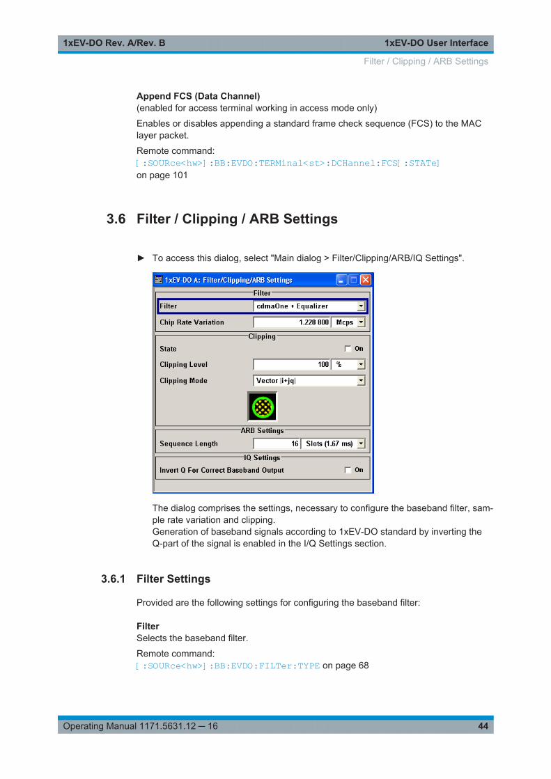
► To access this dialog, select "Main dialog > Filter/Clipping/ARB/IQ Settings".
The dialog comprises the settings, necessary to configure the baseband filter, sam-ple rate variation and clipping.Generation of baseband signals according to 1xEV-DO standard by inverting theQ-part of the signal is enabled in the I/Q Settings section.
3.6.1 Filter Settings
Provided are the following settings for configuring the baseband filter:
FilterSelects the baseband filter.
Remote command: [:SOURce<hw>]:BB:EVDO:FILTer:TYPE on page 68
Filter / Clipping / ARB Settings
1xEV-DO User Interface1xEV-DO Rev. A/Rev. B
45Operating Manual 1171.5631.12 ─ 16
Roll Off Factor or BxTSets the filter parameter.
The filter parameter ("Folloff Factor" or "BxT") depends on the currently selected filtertype. This parameter is preset to the default for each of the predefined filters.
Remote command: [:SOURce<hw>]:BB:EVDO:FILTer:PARameter:APCO25 on page 65[:SOURce<hw>]:BB:EVDO:FILTer:PARameter:COSine on page 66[:SOURce<hw>]:BB:EVDO:FILTer:PARameter:GAUSs on page 66[:SOURce<hw>]:BB:EVDO:FILTer:PARameter:PGAuss on page 67[:SOURce<hw>]:BB:EVDO:FILTer:PARameter:RCOSine on page 67[:SOURce<hw>]:BB:EVDO:FILTer:PARameter:SPHase on page 67
Cut Off Frequency FactorSets the value for the cutoff frequency factor. The cutoff frequency of the filter can beadjusted to reach spectrum mask requirements.
Remote command: [:SOURce<hw>]:BB:EVDO:FILTer:PARameter:LPASs on page 66[:SOURce<hw>]:BB:EVDO:FILTer:PARameter:LPASSEVM on page 66
Chip Rate VariationEnters the chip rate.
The chip rate entry changes the output clock and the modulation bandwidth.
Remote command: [:SOURce<hw>]:BB:EVDO:CRATe:VARiation on page 65
3.6.2 Clipping Settings
Provided are the following settings for configuring the clipping settings:
Clipping State(For reverse link mode only)
Switches baseband clipping on and off.
Baseband clipping is a simple and effective way of reducing the crest factor of the sig-nal. Since clipping is done before to filtering, the procedure does not influence thespectrum. The EVM however increases.
1xEV-DO signals can have high crest factors particularly with many channels and longsequences.
Remote command: [:SOURce<hw>]:BB:EVDO:CLIPping:STATe on page 65
Clipping Level(For reverse link mode only)
Sets the limit for clipping.
This value indicates at what point the signal is clipped. It is specified as a percentage,relative to the highest level. 100% indicates that clipping does not take place.
Filter / Clipping / ARB Settings
1xEV-DO User Interface1xEV-DO Rev. A/Rev. B
46Operating Manual 1171.5631.12 ─ 16
Remote command: [:SOURce<hw>]:BB:EVDO:CLIPping:LEVel on page 64
Clipping Mode(For reverse link mode only)
Selects the clipping method. A graphic illustration of the way in which this two methodswork is given in the dialog.● "Vector | i + jq |"
The limit is related to the amplitude | i + q |. The I and Q components are mappedtogether, the angle is retained.
● "Scalar | i | , | q |"The limit is related to the absolute maximum of all the I and Q values | i | + | q |.The I and Q components are mapped separately, the angle changes.
Remote command: [:SOURce<hw>]:BB:EVDO:CLIPping:MODE on page 64
3.6.3 ARB Settings
Provided are the following settings for configuring the ARB settings:
Sequence Length ARB(For reverse link mode only)
Changes the sequence length of the arbitrary waveform component of the 1xEV-DOsignal. This component is calculated in advance and output in the arbitrary waveformgenerator. It is added to the realtime signal components.
The number of chips is determined from this sequence length. One slot of 1.67msduration equals 2048 chips.
Remote command: [:SOURce<hw>]:BB:EVDO:SLENgth on page 62
3.6.4 I/Q Setting
Provided are the following settings for configuring the IQ settings:
Invert Q for Correct Baseband OutputWith its default 1xEV-DO settings, the R&S Signal Generator generates a standardcompliant RF signal.
If a standard compliant baseband signal is required, enable this parameter to invert theQ-part of the baseband signal.
If both, the RF signal and baseband signal have to be compliant with the 1xEV-DOstandard:● Set "Invert Q for Correct Baseband Output > On"● Set "I/Q Mod > I/Q Settings > I/Q Swap > On"
Remote command: [:SOURce<hw>]:BB:EVDO:IQSWap:STATe on page 68
Filter / Clipping / ARB Settings
1xEV-DO User Interface1xEV-DO Rev. A/Rev. B
47Operating Manual 1171.5631.12 ─ 16
3.7 Trigger/Marker/Clock Settings
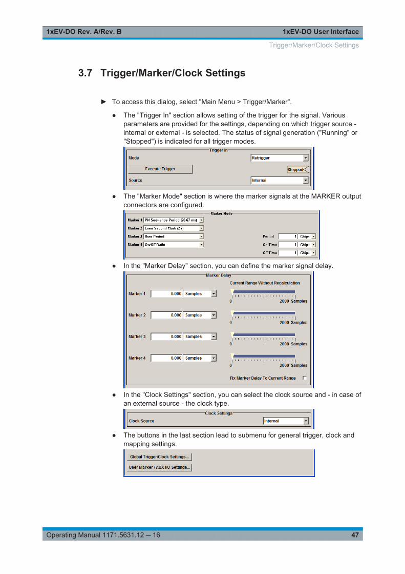
► To access this dialog, select "Main Menu > Trigger/Marker".
● The "Trigger In" section allows setting of the trigger for the signal. Variousparameters are provided for the settings, depending on which trigger source -internal or external - is selected. The status of signal generation ("Running" or"Stopped") is indicated for all trigger modes.
● The "Marker Mode" section is where the marker signals at the MARKER outputconnectors are configured.
● In the "Marker Delay" section, you can define the marker signal delay.
● In the "Clock Settings" section, you can select the clock source and - in case ofan external source - the clock type.
● The buttons in the last section lead to submenu for general trigger, clock andmapping settings.
Trigger/Marker/Clock Settings
1xEV-DO User Interface1xEV-DO Rev. A/Rev. B
48Operating Manual 1171.5631.12 ─ 16
3.7.1 Trigger Settings
In the "Trigger in" dialog, the trigger for the signal is set. Various parameters are provi-ded for the settings, depending on which trigger source - internal or external - isselected. The status of signal generation ("Running" or "Stopped") is indicated for alltrigger modes.
Trigger ModeSelects trigger mode, i.e. determines the effect of a trigger event on the signal genera-tion.● "Auto"
The signal is generated continuously.● "Retrigger"
The signal is generated continuously. A trigger event (internal or external) causes arestart.
● "Armed Auto"The signal is generated only when a trigger event occurs. Then the signal is gener-ated continuously.An "Arm" stops the signal generation. A subsequent trigger event (internal with orexternal) causes a restart.
● "Armed Retrigger"The signal is generated only when a trigger event occurs. Then the signal is gener-ated continuously. Every subsequent trigger event causes a restart.An "Arm" stops signal generation. A subsequent trigger event (internal with orexternal) causes a restart.
● "Single"The signal is generated only when a trigger event occurs. Then the signal is gener-ated once to the length specified at "Signal Duration".Every subsequent trigger event (internal or external) causes a restart.
Remote command: [:SOURce<hw>]:BB:EVDO[:TRIGger]:SEQuence on page 69
Signal Duration UnitAvailable in Single Trigger Mode. Defines the unit for describing the length of the signalsequence to be output.
Remote command: [:SOURce<hw>]:BB:EVDO:TRIGger:SLUNit on page 71
Signal DurationDefines the length of the signal sequence to be output in the "Single" trigger mode.
It is possible to output deliberately just part of the signal, an exact sequence of the sig-nal, or a defined number of repetitions of the signal.
Remote command: [:SOURce<hw>]:BB:EVDO:TRIGger:SLENgth on page 70
Running/StoppedWith enabled modulation, displays the status of signal generation for all trigger modes.● "Running"
Trigger/Marker/Clock Settings
1xEV-DO User Interface1xEV-DO Rev. A/Rev. B
49Operating Manual 1171.5631.12 ─ 16
The signal is generated; a trigger was (internally or externally) initiated in triggeredmode.
● "Stopped"The signal is not generated and the instrument waits for a trigger event.
Remote command: [:SOURce<hw>]:BB:EVDO:TRIGger:RMODe? on page 70
ArmStops the signal generation until subsequent trigger event occurs.
Remote command: [:SOURce<hw>]:BB:EVDO:TRIGger:ARM:EXECute on page 69
Execute TriggerFor internal trigger source, executes trigger manually.
Remote command: [:SOURce<hw>]:BB:EVDO:TRIGger:EXECute on page 69
Trigger SourceSelects trigger source. This setting is effective when a trigger mode other than "Auto"has been selected.● "Internal"
The trigger event is executed by "Execute Trigger".● "Internal (Baseband A/B)"
(two-path instruments)The trigger event is the trigger signal from the second path
● "External (Trigger 1/2)"The trigger event is the active edge of an external trigger signal, supplied at theTRIGGER 1/2 connector.Use the "Global Trigger/Clock Settings" dialog to define the polarity, the triggerthreshold and the input impedance of the trigger signal.
Remote command: [:SOURce<hw>]:BB:EVDO:TRIGger:SOURce on page 71
Sync. Output to External TriggerFor an external trigger signal, enables/disables the output of a signal synchronous tothe external trigger event.● "On"
Corresponds to the default state of this parameter.The signal calculation starts simultaneously with the external trigger event.Because of the processing time of the instrument, the first samples are cut off andno signal is output. After elapsing of the internal processing time, the output signalis synchronous to the trigger event.
Trigger/Marker/Clock Settings
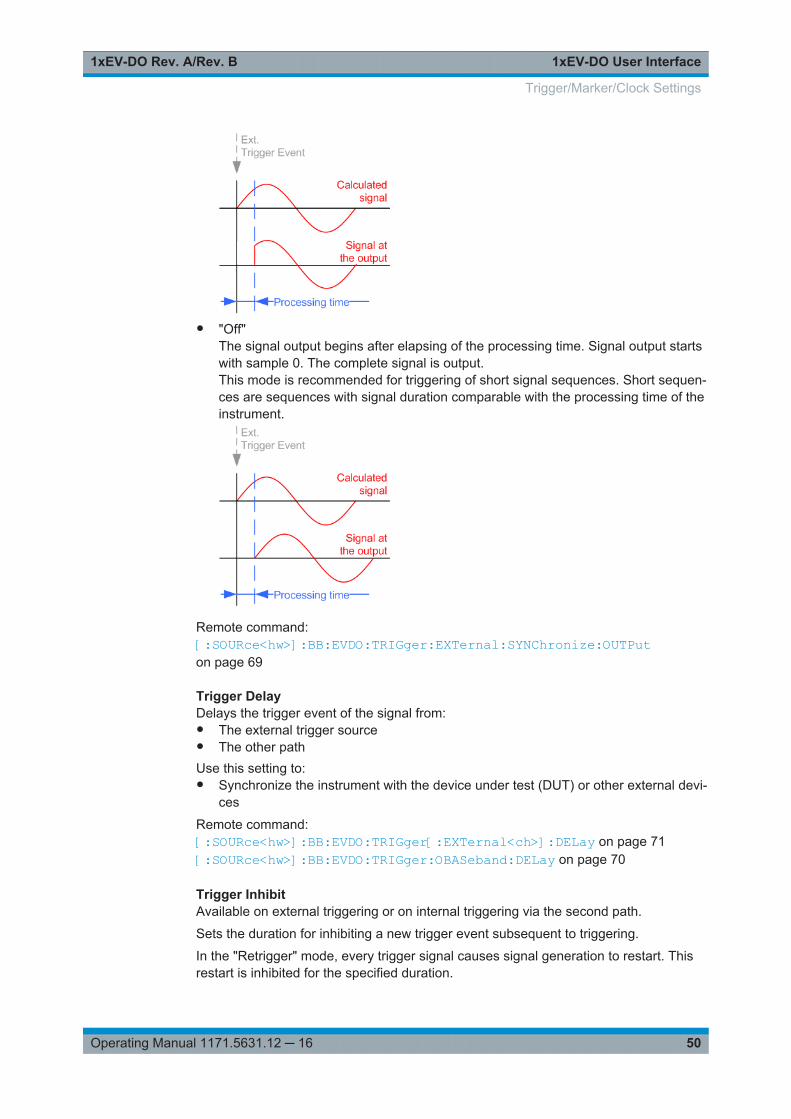
1xEV-DO User Interface1xEV-DO Rev. A/Rev. B
50Operating Manual 1171.5631.12 ─ 16
● "Off"The signal output begins after elapsing of the processing time. Signal output startswith sample 0. The complete signal is output.This mode is recommended for triggering of short signal sequences. Short sequen-ces are sequences with signal duration comparable with the processing time of theinstrument.
Remote command: [:SOURce<hw>]:BB:EVDO:TRIGger:EXTernal:SYNChronize:OUTPuton page 69
Trigger DelayDelays the trigger event of the signal from:● The external trigger source● The other pathUse this setting to:● Synchronize the instrument with the device under test (DUT) or other external devi-
ces
Remote command: [:SOURce<hw>]:BB:EVDO:TRIGger[:EXTernal<ch>]:DELay on page 71[:SOURce<hw>]:BB:EVDO:TRIGger:OBASeband:DELay on page 70
Trigger InhibitAvailable on external triggering or on internal triggering via the second path.
Sets the duration for inhibiting a new trigger event subsequent to triggering.
In the "Retrigger" mode, every trigger signal causes signal generation to restart. Thisrestart is inhibited for the specified duration.
Trigger/Marker/Clock Settings
1xEV-DO User Interface1xEV-DO Rev. A/Rev. B
51Operating Manual 1171.5631.12 ─ 16
For two-path instruments, the trigger inhibit can be set separately for each of the twopaths.
Remote command: [:SOURce<hw>]:BB:EVDO:TRIGger[:EXTernal<ch>]:INHibit on page 72[:SOURce<hw>]:BB:EVDO:TRIGger:OBASeband:INHibit on page 70
3.7.2 Marker Settings
The marker output signal for synchronizing external instruments is configured in themarker settings section "Marker Mode".
The R&S SMBV supports only two markers.
Marker ModeSelects a marker signal for the associated MARKER output.
"Slot (1.67ms)"
A marker signal is generated at the start of each slot (every 1.67 ms).
"PN SequencePeriod (26,67ms)"
A marker signal is generated every 26.67 ms (PN Sequence Period).
"Even SecondMark (2 s)"
A marker signal is generated every 2 seconds.
"ChipSequencePeriod (ARB)"
(For reverse link mode only)A marker signal is generated at the beginning of every ArbitraryWaveform sequence (depending on the set sequence length). Themarker signal is generated regardless of whether an ARB componentis used.
"ON/OFFPeriod"
A regular marker signal that is defined by an on/off ratio is generated.A period lasts one ON and OFF cycle.The "ON Time" and "OFF Time" are each expressed as a number ofsamples and are set in an input field which opens when on/off ratio isselected.
Remote command: [:SOURce<hw>]:BB:EVDO:TRIGger:OUTPut<ch>:ONTime on page 74[:SOURce<hw>]:BB:EVDO:TRIGger:OUTPut<ch>:OFFTime on page 74
"User Period" A marker signal is generated at the beginning of every user-definedperiod. The period is defined in "Period".
Remote command: [:SOURce<hw>]:BB:EVDO:TRIGger:OUTPut<ch>:PERiod on page 74
Remote command: [:SOURce<hw>]:BB:EVDO:TRIGger:OUTPut<ch>:MODE on page 73
Trigger/Marker/Clock Settings
1xEV-DO User Interface1xEV-DO Rev. A/Rev. B
52Operating Manual 1171.5631.12 ─ 16
3.7.3 Marker Delay Settings
The delay of the signals on the marker outputs is set in the "Marker Delay" section.
The R&S SMBV supports two markers.
Marker x DelayEnters the delay between the marker signal at the marker outputs and the start of thesignal.
If the setting "Fix marker delay to dynamic range" is enabled, the setting range isrestricted to the dynamic range. In this range, the delay of the marker signals can beset without restarting the marker and signal.
Remote command: [:SOURce<hw>]:BB:EVDO:TRIGger:OUTPut<ch>:DELay on page 72
Current Range without CalculationDisplays the dynamic range within which the delay of the marker signals can be setwithout restarting the marker and signal.
The delay can be defined by moving the setting mark.
Remote command: [:SOURce<hw>]:BB:EVDO:TRIGger:OUTPut<ch>:DELay:MINimum?on page 73[:SOURce<hw>]:BB:EVDO:TRIGger:OUTPut<ch>:DELay:MAXimum?on page 73
Fix Marker to Current RangeRestricts the marker delay setting range to the dynamic range. In this range, the delaycan be set without restarting the marker and signal.
Remote command: [:SOURce<hw>]:BB:EVDO:TRIGger:OUTPut:DELay:FIXed on page 72
3.7.4 Clock Settings
The clock settings are used to set the clock source.
Sync. Mode(for R&S SMBV only)
Selects the synchronization mode.
This parameter is used to enable generation of precise synchronous signals of severalconnected R&S SMBVs.
Note: If several instruments are connected, the connecting cables from the masterinstrument to the slave one and between each two consecutive slave instruments musthave the same length and type. Avoid unnecessary cable length and branching points.● "None"
The instrument is working in standalone mode.● "Sync. Master"
Trigger/Marker/Clock Settings
1xEV-DO User Interface1xEV-DO Rev. A/Rev. B
53Operating Manual 1171.5631.12 ─ 16
The instrument provides all connected instruments with its synchronization and ref-erence clock signal, also including the trigger signal.
● "Sync. Slave"The instrument receives the synchronization and reference clock signal fromanother instrument working in a master mode.
Remote command: [:SOURce<hw>]:BB:EVDO:CLOCk:SYNChronization:MODE on page 76
Set Synchronization Settings(for R&S SMBV only)
Adjusts the instrument's settings required for the selected synchronization mode.
Remote command: [:SOURce<hw>]:BB:EVDO:CLOCk:SYNChronization:EXECute on page 75
Clock SourceSelects the clock source.● "Internal"
The instrument uses its internal clock reference.● "External"
The instrument expects an external clock reference at the CLOCK connector.The symbol rate must be correctly set to the accuracy specified in the data sheet.To change the polarity of the clock input, use the "Global Trigger/Clock Settings".In the case of two-path instruments, this selection applies to path A.
Remote command: [:SOURce<hw>]:BB:EVDO:CLOCk:SOURce on page 75
Clock ModeEnters the type of externally supplied clock.● "Chip"
A chip clock is supplied via the CLOCK connector.● "Multiple"
A multiple of the chip clock is supplied via the CLOCK connector; the symbol clockis derived internally from it.
Remote command: [:SOURce<hw>]:BB:EVDO:CLOCk:MODE on page 75
Chip Clock MultiplierEnters the multiplication factor for clock type Multiple.
Remote command: [:SOURce<hw>]:BB:EVDO:CLOCk:MULTiplier on page 74
Measured External ClockProvided for permanent monitoring of the enabled and externally supplied clock signal.
Remote command: CLOCk:INPut:FREQuency?
Trigger/Marker/Clock Settings

1xEV-DO User Interface1xEV-DO Rev. A/Rev. B
54Operating Manual 1171.5631.12 ─ 16
3.7.5 Global Settings
The buttons in this section lead to dialogs for general trigger, clock and mapping set-tings.
Global Trigger/Clock SettingsCalls the "Global Trigger/Clock/Input Settings" dialog.
This dialog is used among other things for setting the trigger threshold, the input impe-dance and the polarity of the clock and trigger inputs.
The parameters in this dialog affect all digital modulations and standards, and aredescribed in chapter "Global Trigger/Clock/Input Settings" in the Operating Manual.
User Marker / AUX I/O SettingsCalls the "User Marker AUX I/O Settings" dialog, used to map the connector on therear of the instruments.
See also "User Marker / AUX I/O Settings" in the Operating Manual.
Trigger/Marker/Clock Settings
Remote-Control Commands1xEV-DO Rev. A/Rev. B
55Operating Manual 1171.5631.12 ─ 16
4 Remote-Control CommandsThe following commands are required to generate signals with the 1xEV-DO options ina remote environment. We assume that the R&S Signal Generator has already beenset up for remote operation in a network as described in the R&S Signal Generatordocumentation. A knowledge about the remote control operation and the SCPI com-mand syntax are assumed.
Conventions used in SCPI command descriptionsFor a description of the conventions used in the remote command descriptions, seesection "Remote Control Commands" in the R&S Signal Generator operating manual.
Common Suffixes
The following common suffixes are used in remote commands:
Suffix Value range Description
SOURce<ch> [1]|2 available baseband signals
OUTPut<ch> 1 .. 4 available markers
R&S SMBV supports two markers
EXTernal<ch> 1|2 external trigger connector
CARRier<Ch> 0 .. 21 band class
USER<ST> 1 .. 4 user
TERMinal<ST> 1 .. 4 terminal
Placeholder <root>
For commands that read out or save files in the default directory, the default directoryis set using command MMEM:CDIRectory. The examples in this description use theplace holder <root> in the syntax of the command.● D:\ - for selecting the internal hard disk of a Windows instrument● E:\ - for selecting the memory stick which is inserted at the USB interface of a
Windows instrument● /var/user/ - for selecting the internal flash card of a Linux instrument● /usb/ - for selecting the memory stick which is inserted at the USB interface of a
Linux instrument.
Remote-Control Commands1xEV-DO Rev. A/Rev. B
56Operating Manual 1171.5631.12 ─ 16
Tasks (in manual or remote operation) that are also performed in the base unit in thesame way are not described here.In particular, this includes:● Managing settings and data lists, i.e. storing and loading settings, creating and
accessing data lists, accessing files in a particular directory, etc.● Information on regular trigger, marker and clock signals as well as filter settings, if
appropriate.● General instrument configuration, such as configuring networks and remote opera-
tion● Using the common status registers
For a description of such tasks, see the R&S Signal Generator operating manual.
The following commands specific to the 1xEV-DO are described here:
● Programming Examples..........................................................................................56● General Commands................................................................................................60● Filter/Clipping/ARB Commands.............................................................................. 63● Trigger Commands................................................................................................. 68● Marker Commands..................................................................................................72● Clock Commands....................................................................................................74● Access Network Commands...................................................................................76● Multi-Carrier Configuration Commands...................................................................81● Configure Traffic User Commands..........................................................................83● Configure Access Terminal Commands..................................................................93
4.1 Programming Examples
Example: Performing general tasksThis example shows how to enable the option with predefined settings as basis for fur-ther customization (e.g. defining the transmission direction, etc.). Results and configu-ration are stored with the save/recall function.
// ******************************************************************// Reset instrument first// *******************************************************************RST; *CLS
SOURce1:BB:EVDO:PRESetSOURce1:BB:EVDO:STATe ONSOURce1:BB:EVDO:SETTing:STORe "<root>1xEVDO_def"
// ******************************************************************// Recall settings// ******************************************************************MMEM:CDIR "<root>"
Programming Examples
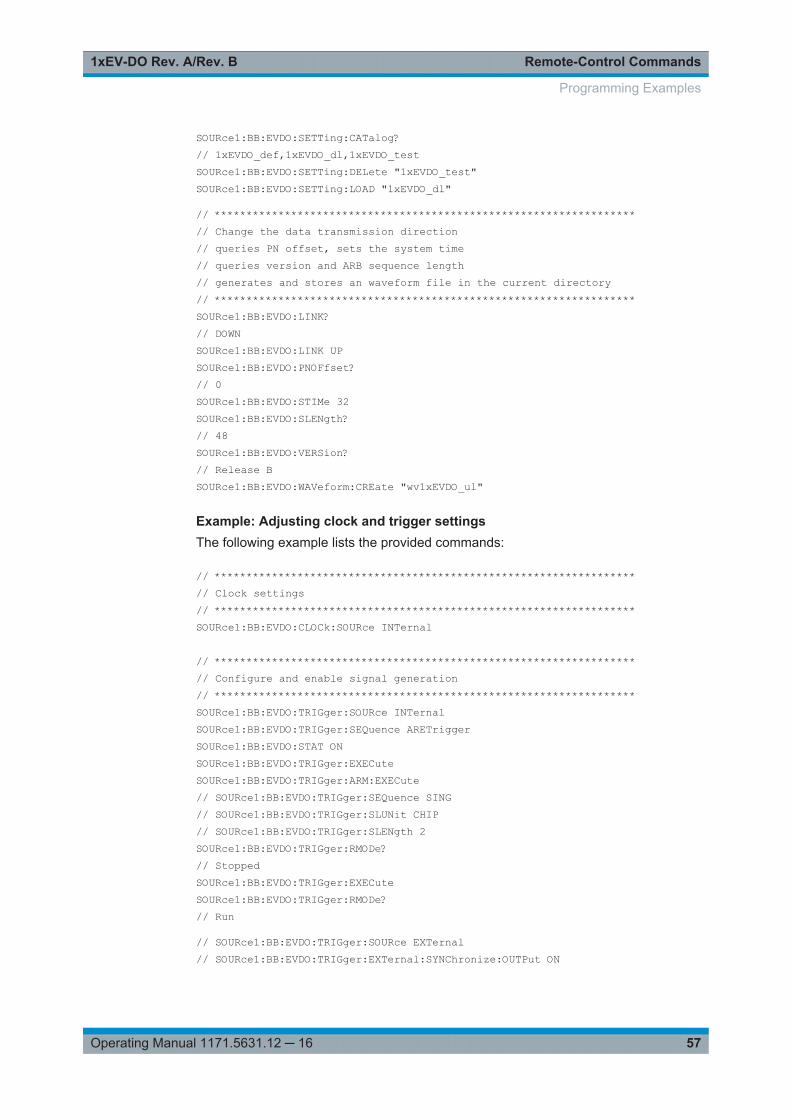
Remote-Control Commands1xEV-DO Rev. A/Rev. B
57Operating Manual 1171.5631.12 ─ 16
SOURce1:BB:EVDO:SETTing:CATalog?// 1xEVDO_def,1xEVDO_dl,1xEVDO_testSOURce1:BB:EVDO:SETTing:DELete "1xEVDO_test"SOURce1:BB:EVDO:SETTing:LOAD "1xEVDO_dl"
// ******************************************************************// Change the data transmission direction// queries PN offset, sets the system time// queries version and ARB sequence length// generates and stores an waveform file in the current directory// ******************************************************************SOURce1:BB:EVDO:LINK?// DOWNSOURce1:BB:EVDO:LINK UPSOURce1:BB:EVDO:PNOFfset?// 0SOURce1:BB:EVDO:STIMe 32SOURce1:BB:EVDO:SLENgth?// 48SOURce1:BB:EVDO:VERSion?// Release BSOURce1:BB:EVDO:WAVeform:CREate "wv1xEVDO_ul"
Example: Adjusting clock and trigger settingsThe following example lists the provided commands:
// ******************************************************************// Clock settings// ******************************************************************SOURce1:BB:EVDO:CLOCk:SOURce INTernal
// ******************************************************************// Configure and enable signal generation// ******************************************************************SOURce1:BB:EVDO:TRIGger:SOURce INTernalSOURce1:BB:EVDO:TRIGger:SEQuence ARETriggerSOURce1:BB:EVDO:STAT ONSOURce1:BB:EVDO:TRIGger:EXECuteSOURce1:BB:EVDO:TRIGger:ARM:EXECute// SOURce1:BB:EVDO:TRIGger:SEQuence SING// SOURce1:BB:EVDO:TRIGger:SLUNit CHIP// SOURce1:BB:EVDO:TRIGger:SLENgth 2SOURce1:BB:EVDO:TRIGger:RMODe?// StoppedSOURce1:BB:EVDO:TRIGger:EXECuteSOURce1:BB:EVDO:TRIGger:RMODe?// Run
// SOURce1:BB:EVDO:TRIGger:SOURce EXTernal// SOURce1:BB:EVDO:TRIGger:EXTernal:SYNChronize:OUTPut ON
Programming Examples
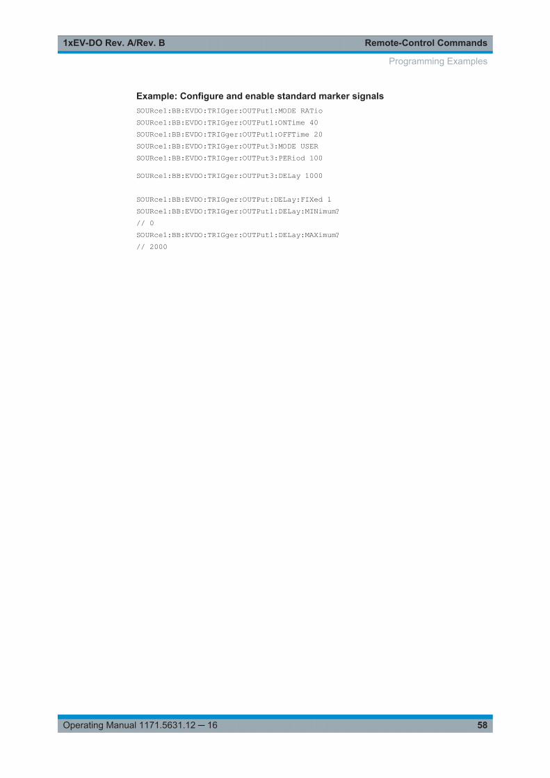
Remote-Control Commands1xEV-DO Rev. A/Rev. B
58Operating Manual 1171.5631.12 ─ 16
Example: Configure and enable standard marker signalsSOURce1:BB:EVDO:TRIGger:OUTPut1:MODE RATioSOURce1:BB:EVDO:TRIGger:OUTPut1:ONTime 40SOURce1:BB:EVDO:TRIGger:OUTPut1:OFFTime 20SOURce1:BB:EVDO:TRIGger:OUTPut3:MODE USERSOURce1:BB:EVDO:TRIGger:OUTPut3:PERiod 100
SOURce1:BB:EVDO:TRIGger:OUTPut3:DELay 1000
SOURce1:BB:EVDO:TRIGger:OUTPut:DELay:FIXed 1SOURce1:BB:EVDO:TRIGger:OUTPut1:DELay:MINimum?// 0SOURce1:BB:EVDO:TRIGger:OUTPut1:DELay:MAXimum?// 2000
Programming Examples

Remote-Control Commands1xEV-DO Rev. A/Rev. B
59Operating Manual 1171.5631.12 ─ 16
Example: Generating a downlink multicarrier signalThis example shows how to enable the multi-carrier configuration and generate a sig-nal composed of four carriers within a selected band class.// ******************************************************************// Reset instrument first// *******************************************************************RST; *CLS
SOURce1:BB:EVDO:LINK?// DOWN
:SOURce1:BB:EVDO:DOWN:MC:BCLass BC11
:SOURce1:BB:EVDO:DOWN:MC:CARRier1:STATe 1:SOURce1:BB:EVDO:DOWN:MC:CARRier2:CHANnel 10:SOURce1:BB:EVDO:DOWN:MC:CARRier2:STATe 1:SOURce1:BB:EVDO:DOWN:MC:CARRier3:CHANnel 5:SOURce1:BB:EVDO:DOWN:MC:CARRier4:CHANnel 500:SOURce1:BB:EVDO:DOWN:MC:CARRier4:STATe 1:SOURce1:BB:EVDO:DOWN:MC:CARRier5:CHANnel 100:SOURce1:BB:EVDO:DOWN:MC:CARRier6:CHANnel 1200:SOURce1:BB:EVDO:DOWN:MC:CARRier6:CHANnel?// 871 (channel 1200 is not allowed; the software selects the next available channel):SOURce1:BB:EVDO:DOWN:MC:CARRier7:CHANnel 1536:SOURce1:BB:EVDO:DOWN:MC:CARRier8:CHANnel 1700:SOURce1:BB:EVDO:DOWN:MC:CARRier8:STATe 1:SOURce1:BB:EVDO:DOWN:MC:CARRier9:CHANnel 240:SOURce1:BB:EVDO:DOWN:MC:STATe 1
:SOURce1:BB:EVDO:STATe 1
:SOURce1:BB:EVDO:DOWN:MC:CFRequency?// 456900000:SOURce1:BB:EVDO:DOWN:MC:CARRier1:FREQuency?// 460000000:SOURce1:BB:EVDO:DOWN:MC:CARRier2:FREQuency?// 460225000:SOURce1:BB:EVDO:DOWN:MC:CARRier4:FREQuency?// 420700000:SOURce1:BB:EVDO:DOWN:MC:CARRier8:FREQuency?//493100000
// apply a carrier delay to reduce the crest factor:SOURce1:BB:EVDO:DOWN:MC:CDELay 0.000001// Carrier#1 is delayed by 0 ns, carrier#2 by 1000 ns, // carrier#4 by 2000 ns, carrie#8 by 3000 ns
Programming Examples
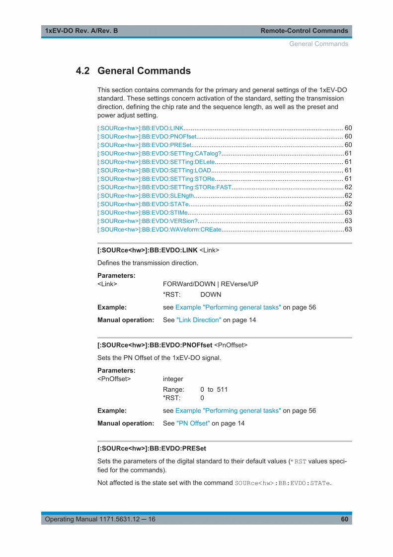
Remote-Control Commands1xEV-DO Rev. A/Rev. B
60Operating Manual 1171.5631.12 ─ 16
4.2 General Commands
This section contains commands for the primary and general settings of the 1xEV-DOstandard. These settings concern activation of the standard, setting the transmissiondirection, defining the chip rate and the sequence length, as well as the preset andpower adjust setting.
[:SOURce<hw>]:BB:EVDO:LINK....................................................................................... 60[:SOURce<hw>]:BB:EVDO:PNOFfset................................................................................ 60[:SOURce<hw>]:BB:EVDO:PRESet................................................................................... 60[:SOURce<hw>]:BB:EVDO:SETTing:CATalog?...................................................................61[:SOURce<hw>]:BB:EVDO:SETTing:DELete...................................................................... 61[:SOURce<hw>]:BB:EVDO:SETTing:LOAD........................................................................ 61[:SOURce<hw>]:BB:EVDO:SETTing:STORe...................................................................... 61[:SOURce<hw>]:BB:EVDO:SETTing:STORe:FAST............................................................. 62[:SOURce<hw>]:BB:EVDO:SLENgth..................................................................................62[:SOURce<hw>]:BB:EVDO:STATe.....................................................................................62[:SOURce<hw>]:BB:EVDO:STIMe..................................................................................... 63[:SOURce<hw>]:BB:EVDO:VERSion?................................................................................63[:SOURce<hw>]:BB:EVDO:WAVeform:CREate...................................................................63
[:SOURce<hw>]:BB:EVDO:LINK <Link>
Defines the transmission direction.
Parameters:<Link> FORWard/DOWN | REVerse/UP
*RST: DOWN
Example: see Example "Performing general tasks" on page 56
Manual operation: See "Link Direction" on page 14
[:SOURce<hw>]:BB:EVDO:PNOFfset <PnOffset>
Sets the PN Offset of the 1xEV-DO signal.
Parameters:<PnOffset> integer
Range: 0 to 511*RST: 0
Example: see Example "Performing general tasks" on page 56
Manual operation: See "PN Offset" on page 14
[:SOURce<hw>]:BB:EVDO:PRESet
Sets the parameters of the digital standard to their default values (*RST values speci-fied for the commands).
Not affected is the state set with the command SOURce<hw>:BB:EVDO:STATe.
General Commands

Remote-Control Commands1xEV-DO Rev. A/Rev. B
61Operating Manual 1171.5631.12 ─ 16
Example: see Example "Performing general tasks" on page 56
Usage: Event
Manual operation: See "Set to Default" on page 12
[:SOURce<hw>]:BB:EVDO:SETTing:CATalog?
Queries the files with 1xEV-DO settings (file extension *.1xevdo) in the default or thespecified directory.
Return values: <Catalog> "<filename1>,<filename2>,..."
Returns a string of filenames separated by commas.
Example: See Example "Performing general tasks" on page 56
Usage: Query only
Manual operation: See "Save/Recall ..." on page 12
[:SOURce<hw>]:BB:EVDO:SETTing:DELete <Filename>
Deletes the selected file from the default or specified directory. Deleted are files withthe file extension *.1xevdo.
Setting parameters: <Filename> string
Example: See Example "Performing general tasks" on page 56
Usage: Setting only
Manual operation: See "Save/Recall ..." on page 12
[:SOURce<hw>]:BB:EVDO:SETTing:LOAD <Filename>
Loads the selected file from the default or the specified directory. Loads are files withextension *.1xevdo.
Setting parameters: <Filename> string
Example: See Example "Performing general tasks" on page 56
Usage: Setting only
Manual operation: See "Save/Recall ..." on page 12
[:SOURce<hw>]:BB:EVDO:SETTing:STORe <Filename>
Stores the current settings into the selected file; the file extension *.1xevdo isassigned automatically.
General Commands
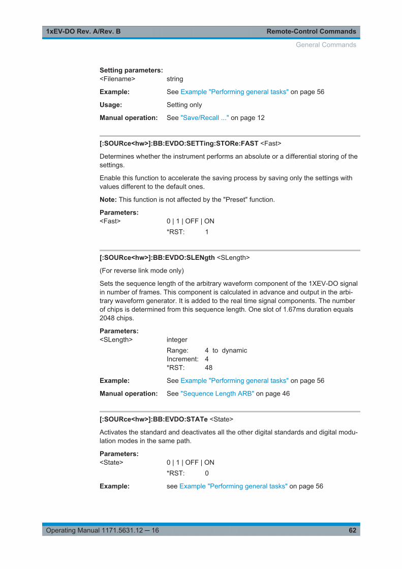
Remote-Control Commands1xEV-DO Rev. A/Rev. B
62Operating Manual 1171.5631.12 ─ 16
Setting parameters: <Filename> string
Example: See Example "Performing general tasks" on page 56
Usage: Setting only
Manual operation: See "Save/Recall ..." on page 12
[:SOURce<hw>]:BB:EVDO:SETTing:STORe:FAST <Fast>
Determines whether the instrument performs an absolute or a differential storing of thesettings.
Enable this function to accelerate the saving process by saving only the settings withvalues different to the default ones.
Note: This function is not affected by the "Preset" function.
Parameters:<Fast> 0 | 1 | OFF | ON
*RST: 1
[:SOURce<hw>]:BB:EVDO:SLENgth <SLength>
(For reverse link mode only)
Sets the sequence length of the arbitrary waveform component of the 1XEV-DO signalin number of frames. This component is calculated in advance and output in the arbi-trary waveform generator. It is added to the real time signal components. The numberof chips is determined from this sequence length. One slot of 1.67ms duration equals2048 chips.
Parameters:<SLength> integer
Range: 4 to dynamicIncrement: 4*RST: 48
Example: See Example "Performing general tasks" on page 56
Manual operation: See "Sequence Length ARB" on page 46
[:SOURce<hw>]:BB:EVDO:STATe <State>
Activates the standard and deactivates all the other digital standards and digital modu-lation modes in the same path.
Parameters:<State> 0 | 1 | OFF | ON
*RST: 0
Example: see Example "Performing general tasks" on page 56
General Commands
Remote-Control Commands1xEV-DO Rev. A/Rev. B
63Operating Manual 1171.5631.12 ─ 16
Manual operation: See "State" on page 12
[:SOURce<hw>]:BB:EVDO:STIMe <STime>
Sets the System Time value of the 1xEV-DO signal and the base station. The SystemTime value is expressed in units of 1.67 ms intervals (80 ms/ 48).
Note: In uplink, the value selected for system time must be multiple of 16.
Parameters:<STime> integer
Range: 0 to 2199023255551*RST: 0
Example: see Example "Performing general tasks" on page 56
Manual operation: See "System Time" on page 14
[:SOURce<hw>]:BB:EVDO:VERSion?
Queries the version of the 1xEV-DO standard underlying the definitions
Return values: <Version> string
Example: see Example "Performing general tasks" on page 56
Usage: Query only
Manual operation: See "1xEV-DO Version" on page 13
[:SOURce<hw>]:BB:EVDO:WAVeform:CREate <Filename>
Creates a waveform using the current settings. The file is stored with the predefinedfile extension *.wv. The filename and the directory it is stored in are user-definable.
Setting parameters: <Filename> string
Example: See Example "Performing general tasks" on page 56
Usage: Setting only
Manual operation: See "Generate Waveform File" on page 13
4.3 Filter/Clipping/ARB Commands
[:SOURce<hw>]:BB:EVDO:CLIPping:LEVel........................................................................64[:SOURce<hw>]:BB:EVDO:CLIPping:MODE.......................................................................64[:SOURce<hw>]:BB:EVDO:CLIPping:STATe...................................................................... 65[:SOURce<hw>]:BB:EVDO:CRATe:VARiation.....................................................................65[:SOURce<hw>]:BB:EVDO:FILTer:PARameter:APCO25......................................................65
Filter/Clipping/ARB Commands
Remote-Control Commands1xEV-DO Rev. A/Rev. B
64Operating Manual 1171.5631.12 ─ 16
[:SOURce<hw>]:BB:EVDO:FILTer:PARameter:COSine....................................................... 66[:SOURce<hw>]:BB:EVDO:FILTer:PARameter:GAUSs........................................................66[:SOURce<hw>]:BB:EVDO:FILTer:PARameter:LPASs.........................................................66[:SOURce<hw>]:BB:EVDO:FILTer:PARameter:LPASSEVM................................................. 66[:SOURce<hw>]:BB:EVDO:FILTer:PARameter:PGAuss.......................................................67[:SOURce<hw>]:BB:EVDO:FILTer:PARameter:RCOSine.....................................................67[:SOURce<hw>]:BB:EVDO:FILTer:PARameter:SPHase.......................................................67[:SOURce<hw>]:BB:EVDO:FILTer:TYPE............................................................................68[:SOURce<hw>]:BB:EVDO:IQSWap:STATe....................................................................... 68
[:SOURce<hw>]:BB:EVDO:CLIPping:LEVel <Level>
(For reverse link mode only)
The command sets the limit for level clipping (Clipping). This value indicates at whatpoint the signal is clipped. It is specified as a percentage, relative to the highest level.100% indicates that clipping does not take place.
Level clipping is activated with the command SOUR:BB:EVDO:CLIP:STAT ONParameters:<Level> integer
Range: 0 PCT to 100 PCTIncrement: 1 PCT*RST: 100 PCT
Example: BB:EVDO:CLIP:LEV 80PCTsets the limit for level clipping to 80% of the maximum level.BB:EVDO:CLIP:STAT ONactivates level clipping.
Manual operation: See "Clipping Level" on page 45
[:SOURce<hw>]:BB:EVDO:CLIPping:MODE <Mode>
(For reverse link mode only)
Sets the method for level clipping.
Parameters:<Mode> VECTor | SCALar
VECTorThe reference level is the amplitude | i+jq |SCALarThe reference level is the absolute maximum of the I and Q val-ues.*RST: VECTor
Example: BB:EVDO:CLIP:MODE SCALBB:EVDO:CLIP:LEV 80PCTSets the limit for level clipping to 80% of this maximum level.BB:EVDO:CLIP:STAT ON
Filter/Clipping/ARB Commands
Remote-Control Commands1xEV-DO Rev. A/Rev. B
65Operating Manual 1171.5631.12 ─ 16
Manual operation: See "Clipping Mode" on page 46
[:SOURce<hw>]:BB:EVDO:CLIPping:STATe <State>
(For reverse link mode only)
The command activates level clipping (Clipping). The value is defined with the com-mandBB:EVDO:CLIPping:LEVel, the mode of calculation with the commandBB:EVDO:CLIPping:MODE.
Parameters:<State> 0 | 1 | OFF | ON
*RST: OFF
Example: BB:EVDO:CLIP:STAT ONactivates level clipping.
Manual operation: See "Clipping State" on page 45
[:SOURce<hw>]:BB:EVDO:CRATe:VARiation <Variation>
Enters the output chip rate.
The output chip rate changes the output clock and the modulation bandwidth, as wellas the synchronization signals that are output. It does not affect the calculated chipsequence.
Parameters:<Variation> float
Range: 1 Mcps to 5 McpsIncrement: 1E-6 Mcps (1cps)*RST: 1.2288 Mcps
Example: BB:EVDO:CRAT:VAR 4086001sets the chip rate to 4.08 Mcps.
Manual operation: See "Chip Rate Variation" on page 45
[:SOURce<hw>]:BB:EVDO:FILTer:PARameter:APCO25 <Apco25>
Sets the rolloff factor for filter type APCO25.
Parameters:<Apco25> float
Range: 0.05 to 0.99Increment: 0.01*RST: 0.2
Example: BB:EVDO:FILT:PAR:APCO25 0.2Sets the rolloff factor to 0.2 for filter type APCO25.
Manual operation: See "Roll Off Factor or BxT" on page 45
Filter/Clipping/ARB Commands

Remote-Control Commands1xEV-DO Rev. A/Rev. B
66Operating Manual 1171.5631.12 ─ 16
[:SOURce<hw>]:BB:EVDO:FILTer:PARameter:COSine <Cosine>
Sets the rolloff factor for the Cosine filter type.
Parameters:<Cosine> float
Range: 0.05 to 1Increment: 0.01*RST: 0.1
Example: BB:EVDO:FILT:PAR:COS 0.35Sets the rolloff factor to 0.35 for filter type Cosine.
Manual operation: See "Roll Off Factor or BxT" on page 45
[:SOURce<hw>]:BB:EVDO:FILTer:PARameter:GAUSs <Gauss>
Sets the rolloff factor for the Gauss filter type.
Parameters:<Gauss> float
Range: 0.15 to 2.5Increment: 0.01*RST: 0.5
Example: BB:EVDO:FILT:PAR:GAUS 0.5Sets BxT to 0.5 for the Gauss filter type.
Manual operation: See "Roll Off Factor or BxT" on page 45
[:SOURce<hw>]:BB:EVDO:FILTer:PARameter:LPASs <LPass>
Sets the cutoff frequency factor for the lowpass filter (ACP Opt.) type.
Parameters:<LPass> float
Range: 0.05 to 2Increment: 0.01*RST: 0.5
Example: BB:EVDO:FILT:PAR:LPAS 0.5The cut of frequency factor is set to 0.5.
Manual operation: See "Cut Off Frequency Factor" on page 45
[:SOURce<hw>]:BB:EVDO:FILTer:PARameter:LPASSEVM <LPassEvm>
Sets the cutoff frequency factor for the lowpass filter (EVM Opt.) type.
Filter/Clipping/ARB Commands
Remote-Control Commands1xEV-DO Rev. A/Rev. B
67Operating Manual 1171.5631.12 ─ 16
Parameters:<LPassEvm> float
Range: 0.05 to 2Increment: 0.01*RST: 0.5
Example: BB:EVDO:FILT:PAR:LPASSEVM 0.5The cut of frequency factor is set to 0.5.
Manual operation: See "Cut Off Frequency Factor" on page 45
[:SOURce<hw>]:BB:EVDO:FILTer:PARameter:PGAuss <PGauss>
Sets the rolloff factor for the Pure Gauss filter type.
Parameters:<PGauss> float
Range: 0.15 to 2.5Increment: 0.01*RST: 0.5
Example: BB:EVDO:FILT:PAR:GAUS 0.5Sets BxT to 0.5 for the Pure Gauss filter type.
Manual operation: See "Roll Off Factor or BxT" on page 45
[:SOURce<hw>]:BB:EVDO:FILTer:PARameter:RCOSine <RCosine>
Sets the rolloff factor for the Root Cosine filter type.
Parameters:<RCosine> float
Range: 0.05 to 1Increment: 0.01*RST: 0.15
Example: BB:EVDO:FILT:PAR:RCOS 0.22Sets the rolloff factor to 0. 22 for filter type Root Cosine.
Manual operation: See "Roll Off Factor or BxT" on page 45
[:SOURce<hw>]:BB:EVDO:FILTer:PARameter:SPHase <SPhase>
Sets BxT for the Split Phase filter type.
Parameters:<SPhase> float
Range: 0.15 to 2.5Increment: 0.01*RST: 2
Filter/Clipping/ARB Commands
Remote-Control Commands1xEV-DO Rev. A/Rev. B
68Operating Manual 1171.5631.12 ─ 16
Example: BB:EVDO:FILT:PAR:SPH 0.5Sets BxT to 0.5 for the Split Phase filter type.
Manual operation: See "Roll Off Factor or BxT" on page 45
[:SOURce<hw>]:BB:EVDO:FILTer:TYPE <Type>
The command selects the filter type.
Parameters:<Type> RCOSine | COSine | GAUSs | LGAuss | CONE | COF705 |
COEQualizer | COFequalizer | C2K3x | APCO25 | SPHase |RECTangle | PGAuss | LPASs | DIRac | ENPShape |EWPShape | LPASSEVM*RST: Downlink: COEQ; Uplink: CONE
Example: BB:EVDO:FILT:TYPE CONESets the filter type CdmaOne. This filter type is defined by thestandard for the uplink.
Manual operation: See "Filter" on page 44
[:SOURce<hw>]:BB:EVDO:IQSWap:STATe <State>
Inverts the Q-part of the baseband signal
Parameters:<State> 0 | 1 | OFF | ON
*RST: 0
Example: SOURce1:BB:EVDO:IQSWap:STATe ONinverts the Q-part of the baseband signalSOURce:IQ:SWAP:STATe ONswaps the I and Q signals
Manual operation: See "Invert Q for Correct Baseband Output" on page 46
4.4 Trigger Commands
[:SOURce<hw>]:BB:EVDO[:TRIGger]:SEQuence................................................................69[:SOURce<hw>]:BB:EVDO:TRIGger:ARM:EXECute............................................................69[:SOURce<hw>]:BB:EVDO:TRIGger:EXECute.................................................................... 69[:SOURce<hw>]:BB:EVDO:TRIGger:EXTernal:SYNChronize:OUTPut...................................69[:SOURce<hw>]:BB:EVDO:TRIGger:OBASeband:DELay.....................................................70[:SOURce<hw>]:BB:EVDO:TRIGger:OBASeband:INHibit.....................................................70[:SOURce<hw>]:BB:EVDO:TRIGger:RMODe?....................................................................70[:SOURce<hw>]:BB:EVDO:TRIGger:SLENgth.................................................................... 70[:SOURce<hw>]:BB:EVDO:TRIGger:SLUNit....................................................................... 71
Trigger Commands
Remote-Control Commands1xEV-DO Rev. A/Rev. B
69Operating Manual 1171.5631.12 ─ 16
[:SOURce<hw>]:BB:EVDO:TRIGger:SOURce.....................................................................71[:SOURce<hw>]:BB:EVDO:TRIGger[:EXTernal<ch>]:DELay................................................ 71[:SOURce<hw>]:BB:EVDO:TRIGger[:EXTernal<ch>]:INHibit................................................ 72
[:SOURce<hw>]:BB:EVDO[:TRIGger]:SEQuence <Sequence>
Selects the trigger mode:● AUTO = auto● RETRigger = retrigger● AAUTo = armed auto● ARETrigger = armed retrigger● SINGle = single
Parameters:<Sequence> AUTO | RETRigger | AAUTo | ARETrigger | SINGle
*RST: AUTO
Example: see Example "Adjusting clock and trigger settings" on page 57
Manual operation: See "Trigger Mode" on page 48
[:SOURce<hw>]:BB:EVDO:TRIGger:ARM:EXECute
Stops signal generation; a subsequent internal or external trigger event restart signalgeneration.
Example: see Example "Adjusting clock and trigger settings" on page 57
Usage: Event
Manual operation: See "Arm" on page 49
[:SOURce<hw>]:BB:EVDO:TRIGger:EXECute
Executes a trigger.
Example: see Example "Adjusting clock and trigger settings" on page 57
Usage: Event
Manual operation: See "Execute Trigger" on page 15
[:SOURce<hw>]:BB:EVDO:TRIGger:EXTernal:SYNChronize:OUTPut <Output>
Enables/disables output of the signal synchronous to the external trigger event.
Parameters:<Output> 0 | 1 | OFF | ON
*RST: 1
Example: See Example "Adjusting clock and trigger settings" on page 57
Trigger Commands
Remote-Control Commands1xEV-DO Rev. A/Rev. B
70Operating Manual 1171.5631.12 ─ 16
Manual operation: See "Sync. Output to External Trigger" on page 49
[:SOURce<hw>]:BB:EVDO:TRIGger:OBASeband:DELay <Delay>
When triggering via the other basebands, delays the trigger event compared to the onein the other baseband.
Parameters:<Delay> float
Range: 0 to 65535Increment: 0.01*RST: 0
Example: see [:SOURce<hw>]:BB:EVDO:TRIGger:OBASeband:INHibit on page 70
Manual operation: See "Trigger Delay" on page 50
[:SOURce<hw>]:BB:EVDO:TRIGger:OBASeband:INHibit <Inhibit>
For triggering via the other path, specifies the duration by which a restart is inhibited.
Parameters:<Inhibit> integer
Range: 0 to 67108863*RST: 0
Example: BB:EVDO:TRIG:SOUR OBASsets triggering by the other pathBB:EVDO:TRIG:INH 200sets a restart inhibit for 200 chips following a trigger event.BB:EVDO:TRIG:OBAS:DEL 50sets a delay of 50 symbols for the trigger.
Manual operation: See "Trigger Inhibit" on page 50
[:SOURce<hw>]:BB:EVDO:TRIGger:RMODe?
Queries the signal generation status.
Return values: <RMode> STOP | RUN
Example: see Example "Adjusting clock and trigger settings" on page 57
Usage: Query only
Manual operation: See "Running/Stopped" on page 48
[:SOURce<hw>]:BB:EVDO:TRIGger:SLENgth <SLength>
Defines the length of the signal sequence that is output in the SINGle trigger mode.
Trigger Commands
Remote-Control Commands1xEV-DO Rev. A/Rev. B
71Operating Manual 1171.5631.12 ─ 16
Parameters:<SLength> integer
Range: 1 to 4294967295*RST: 1
Example: See Example "Adjusting clock and trigger settings" on page 57
Manual operation: See "Signal Duration" on page 48
[:SOURce<hw>]:BB:EVDO:TRIGger:SLUNit <SLunit>
Defines the unit for the entry of the length of the signal sequence.
Parameters:<SLunit> SLOT | CHIP | SEQuence
*RST: SEQuence
Example: See Example "Adjusting clock and trigger settings" on page 57
Manual operation: See "Signal Duration Unit" on page 48
[:SOURce<hw>]:BB:EVDO:TRIGger:SOURce <Source>
Selects the trigger source:● INTernal: manual trigger or *TRG.● EXTernal|BEXTernal: trigger signal on the TRIGGER 1/2 connector.● OBASeband: trigger signal from the other path
Parameters:<Source> INTernal|OBASeband|BEXTernal|EXTernal
*RST: INTernal
Example: See Example "Adjusting clock and trigger settings" on page 57
Manual operation: See "Trigger Source" on page 49
[:SOURce<hw>]:BB:EVDO:TRIGger[:EXTernal<ch>]:DELay <Delay>
Specifies the trigger delay (expressed as a number of chips) for external triggering.
Parameters:<Delay> float
Range: 0 to 65535Increment: 0.01*RST: 0
Example: see [:SOURce<hw>]:BB:EVDO:TRIGger[:EXTernal<ch>]:INHibit on page 72
Manual operation: See "Trigger Delay" on page 50
Trigger Commands
Remote-Control Commands1xEV-DO Rev. A/Rev. B
72Operating Manual 1171.5631.12 ─ 16
[:SOURce<hw>]:BB:EVDO:TRIGger[:EXTernal<ch>]:INHibit <Inhibit>
Specifies the number of chips by which a restart is to be inhibited following a triggerevent. This command applies only in the case of external triggering.
Parameters:<Inhibit> integer
Range: 0 to 67108863*RST: 0
Example: BB:EVDO:TRIG:SOUR EXTselects an external triggerBB:EVDO:TRIG:INH 200sets a restart inhibit for 200 chips following a trigger event.BB:EVDO:TRIG:DEL 50sets a delay of 50 symbols for the trigger.
Manual operation: See "Trigger Inhibit" on page 50
4.5 Marker Commands
[:SOURce<hw>]:BB:EVDO:TRIGger:OUTPut:DELay:FIXed................................................. 72[:SOURce<hw>]:BB:EVDO:TRIGger:OUTPut<ch>:DELay....................................................72[:SOURce<hw>]:BB:EVDO:TRIGger:OUTPut<ch>:DELay:MINimum?................................... 73[:SOURce<hw>]:BB:EVDO:TRIGger:OUTPut<ch>:DELay:MAXimum?.................................. 73[:SOURce<hw>]:BB:EVDO:TRIGger:OUTPut<ch>:MODE....................................................73[:SOURce<hw>]:BB:EVDO:TRIGger:OUTPut<ch>:ONTime................................................. 74[:SOURce<hw>]:BB:EVDO:TRIGger:OUTPut<ch>:OFFTime................................................74[:SOURce<hw>]:BB:EVDO:TRIGger:OUTPut<ch>:PERiod...................................................74
[:SOURce<hw>]:BB:EVDO:TRIGger:OUTPut:DELay:FIXed <Fixed>
Restricts the marker delay setting range to the dynamic range.
Parameters:<Fixed> 0 | 1 | OFF | ON
*RST: 0
Example: See Example "Configure and enable standard marker signals"on page 58
Manual operation: See "Fix Marker to Current Range" on page 52
[:SOURce<hw>]:BB:EVDO:TRIGger:OUTPut<ch>:DELay <Delay>
Defines the delay between the signal on the marker outputs and the start of the sig-nals.
Marker Commands
Remote-Control Commands1xEV-DO Rev. A/Rev. B
73Operating Manual 1171.5631.12 ─ 16
Parameters:<Delay> float
Range: 0 to maxIncrement: 0.001*RST: 0
Example: See Example "Configure and enable standard marker signals"on page 58
Manual operation: See "Marker x Delay" on page 52
[:SOURce<hw>]:BB:EVDO:TRIGger:OUTPut<ch>:DELay:MINimum?[:SOURce<hw>]:BB:EVDO:TRIGger:OUTPut<ch>:DELay:MAXimum?Queries the min/max marker delay.
Return values: <Maximum> float
Range: 0 to max
Example: See Example "Configure and enable standard marker signals"on page 58
Usage: Query only
Manual operation: See "Current Range without Calculation" on page 52
[:SOURce<hw>]:BB:EVDO:TRIGger:OUTPut<ch>:MODE <Mode>
Defines the signal for the selected marker output.
Parameters:<Mode> SLOT | PNSPeriod | ESM | CSPeriod | USER | RATio | TRIGger
SLOTEach slot (every 1.67 ms)PNSPeriodEvery 26.67 ms (PN Sequence Period)ESMEvery 2 s (even second mark).CSPeriodEach arbitrary waveform sequenceRATioRegular marker signalUSEREvery user-defined period.TRIGgerA received internal or external trigger signal is output at themarker connector.*RST: SLOT
Marker Commands
Remote-Control Commands1xEV-DO Rev. A/Rev. B
74Operating Manual 1171.5631.12 ─ 16
Example: SOURce:BB:EVDO:TRIGger:OUTPut2:MODE ESMselects the even second mark clock (every 2 seconds) on theoutput for marker signal 2
Manual operation: See "Marker Mode" on page 51
[:SOURce<hw>]:BB:EVDO:TRIGger:OUTPut<ch>:ONTime <OnTime>[:SOURce<hw>]:BB:EVDO:TRIGger:OUTPut<ch>:OFFTime <OffTime>
Sets the duration during which the marker output is on or off.
Parameters:<OffTime> integer
Range: 1 to 16777215*RST: 1
Example: See Example "Configure and enable standard marker signals"on page 58
Manual operation: See "Marker Mode" on page 51
[:SOURce<hw>]:BB:EVDO:TRIGger:OUTPut<ch>:PERiod <Period>
Sets the repetition rate for the signal at the marker outputs.
Parameters:<Period> integer
Range: 2 to 16777215*RST: 2
Example: See Example "Configure and enable standard marker signals"on page 58
Manual operation: See "Marker Mode" on page 51
4.6 Clock Commands
[:SOURce<hw>]:BB:EVDO:CLOCk:MULTiplier................................................................... 74[:SOURce<hw>]:BB:EVDO:CLOCk:SOURce...................................................................... 75[:SOURce<hw>]:BB:EVDO:CLOCk:MODE......................................................................... 75[:SOURce<hw>]:BB:EVDO:CLOCk:SYNChronization:EXECute............................................ 75[:SOURce<hw>]:BB:EVDO:CLOCk:SYNChronization:MODE................................................76
[:SOURce<hw>]:BB:EVDO:CLOCk:MULTiplier <Multiplier>
Sets the multiplier for clock type Multiplied.
For two-path instruments, the only numerical suffix allowed for SOURce is 1, since theexternal clock source is permanently allocated to path A.
Clock Commands
Remote-Control Commands1xEV-DO Rev. A/Rev. B
75Operating Manual 1171.5631.12 ─ 16
Parameters:<Multiplier> integer
Range: 1 to 64*RST: 4
Example: See Example "Adjusting clock and trigger settings" on page 57
Manual operation: See "Chip Clock Multiplier" on page 53
[:SOURce<hw>]:BB:EVDO:CLOCk:SOURce <Source>
The command selects the clock source.
For two-path instruments, selecting EXTernal is only possible for path A, since theexternal clock source is permanently allocated to path A. Selection AINternal is onlypossible for path B.
Parameters:<Source> INTernal | EXTernal | AINTernal
INTernalThe internal clock reference is used.EXTernalThe external clock reference is supplied to the CLOCK connec-tor. Commands :BB:EVDO:CLOCk:MODE and :MULTiplierare used to enter the type of the external clock.AINTernalThe clock source of path A is used for path B.*RST: INTernal
Example: See Example "Adjusting clock and trigger settings" on page 57
Manual operation: See "Clock Source" on page 53
[:SOURce<hw>]:BB:EVDO:CLOCk:MODE <Mode>
Sets the type of externally supplied clock.
For two-path instruments, the only numerical suffix allowed for SOURce is 1, since theexternal clock source is permanently allocated to path A.
Parameters:<Mode> CHIP | MCHip
*RST: CHIP
Example: See Example "Adjusting clock and trigger settings" on page 57
Manual operation: See "Clock Mode" on page 53
[:SOURce<hw>]:BB:EVDO:CLOCk:SYNChronization:EXECute
Performs automatically adjustment of the instrument's settings required for the syn-chronization mode, set with the command BB:EVDO:CLOC:SYNC:MODE.
Clock Commands
Remote-Control Commands1xEV-DO Rev. A/Rev. B
76Operating Manual 1171.5631.12 ─ 16
Example: BB:EVDO:CLOC:SYNC:MODE MASTthe instrument is configured to work as a master one.BB:EVDO:CLOC:SYNC:EXECall synchronizations settings are adjusted accordingly.
Usage: Event
Manual operation: See "Set Synchronization Settings" on page 53
[:SOURce<hw>]:BB:EVDO:CLOCk:SYNChronization:MODE <Mode>
Selects the synchronization mode.
This parameter is used to enable generation of precise synchronous signal of severalconnected R&S SMBVs.
Note: If several instruments are connected, the connecting cables from the masterinstrument to the slave one and between each two consecutive slave instruments musthave the same length and type. Avoid unnecessary cable length and branching points.
Parameters:<Mode> NONE | MASTer | SLAVe
NONEThe instrument is working in stand-alone mode.MASTerThe instrument provides all connected instrument with its syn-chronization (including the trigger signal) and reference clocksignal.SLAVeThe instrument receives the synchronization and reference clocksignal from another instrument working in a master mode.*RST: NONE
Example: BB:EVDO:CLOC:SYNC:MODE MASTThe instrument is configured to work as a master one.
Manual operation: See "Sync. Mode" on page 52
4.7 Access Network Commands
[:SOURce<hw>]:BB:EVDO:ANETwork:CCHannel:PSOFfset................................................ 77[:SOURce<hw>]:BB:EVDO:ANETwork:CCHannel:RATE......................................................77[:SOURce<hw>]:BB:EVDO:ANETwork:CCHannel:REVision:MAXimum................................. 77[:SOURce<hw>]:BB:EVDO:ANETwork:CCHannel:REVision:MINimum.................................. 78[:SOURce<hw>]:BB:EVDO:ANETwork:CCHannel:STATe.................................................... 78[:SOURce<hw>]:BB:EVDO:ANETwork:CPMode..................................................................78[:SOURce<hw>]:BB:EVDO:ANETwork:OUCount.................................................................78[:SOURce<hw>]:BB:EVDO:ANETwork:PCHannel:STATe?...................................................79[:SOURce<hw>]:BB:EVDO:ANETwork:RAB:LENGth........................................................... 79[:SOURce<hw>]:BB:EVDO:ANETwork:RAB:LEVel.............................................................. 79
Access Network Commands
Remote-Control Commands1xEV-DO Rev. A/Rev. B
77Operating Manual 1171.5631.12 ─ 16
[:SOURce<hw>]:BB:EVDO:ANETwork:RAB:MAC:INDex......................................................80[:SOURce<hw>]:BB:EVDO:ANETwork:RAB:OFFSet........................................................... 80[:SOURce<hw>]:BB:EVDO:ANETwork:RAB:STATe.............................................................80[:SOURce<hw>]:BB:EVDO:ANETwork:SUBType................................................................ 80
[:SOURce<hw>]:BB:EVDO:ANETwork:CCHannel:PSOFfset <PSoffset>
Sets the offset (in slots) from the start of control channel cycle to the start of the syn-chronous message capsule that contains the Sync Message.
Parameters:<PSoffset> integer
Range: 0 to 3*RST: 0
Example: BB:EVDO:ANET:CCH:PSOF 2sets the packet start offset for the control channel to 2.
Manual operation: See "Packet Start Offset" on page 17
[:SOURce<hw>]:BB:EVDO:ANETwork:CCHannel:RATE <Rate>
Sets the rate that the control channel messages are transmitted at.
Parameters:<Rate> DR4K8 | DR9K6 | DR19K2 | DR38K4 | DR76K8 | DR153K6 |
DR307K2 | DR614K4 | DR921K6 | DR1228K8 | DR1536K |DR1843K2 | DR2457K6 | DR3072K | DR460K8 | DR768K |DR1075K2 | DR2150K4 | DR3686K4 | DR4300K8 | DR4915K2*RST: 38.4 kbps
Example: BB:EVDO:ANET:CCH:RATE DR76K8sets the control channel rate to 76.8 kbps.
Manual operation: See "Rate (Control Channel)" on page 17
[:SOURce<hw>]:BB:EVDO:ANETwork:CCHannel:REVision:MAXimum<Maximum>
Sets the value of the maximum revision field within the control channel message.
Parameters:<Maximum> integer
Range: 0 to 255*RST: 1
Example: BB:EVDO:ANET:CCH:REV:MAX 10sets the value of the maximum revision field to 10.
Manual operation: See "Maximum Revision" on page 17
Access Network Commands
Remote-Control Commands1xEV-DO Rev. A/Rev. B
78Operating Manual 1171.5631.12 ─ 16
[:SOURce<hw>]:BB:EVDO:ANETwork:CCHannel:REVision:MINimum <Minimum>
Sets the value of the minimum revision field within the control channel message.
Parameters:<Minimum> integer
Range: 0 to 255*RST: 1
Example: BB:EVDO:ANET:CCH:REV:MIN 1sets the value of the minimum revision field to 1.
Manual operation: See "Minimum Revision" on page 17
[:SOURce<hw>]:BB:EVDO:ANETwork:CCHannel:STATe <State>
Enables or disables the control channel messages.
Parameters:<State> 0 | 1 | OFF | ON
*RST: 0
Example: BB:EVDO:ANET:CCH:STAT ONenables the control channel message.
Manual operation: See "State (Control Channel)" on page 16
[:SOURce<hw>]:BB:EVDO:ANETwork:CPMode <CpMode>
Enables or disables a special mode within the 1xEV-DO generator.
Note: During the special mode, all other parameters do not affect the signal output.
Parameters:<CpMode> 0 | 1 | OFF | ON
*RST: 0
Example: BB:EVDO:ANET:CPM ONenables the special mode.
Manual operation: See "Continuous Pilot Mode" on page 16
[:SOURce<hw>]:BB:EVDO:ANETwork:OUCount <OuCount>
Sets the number of additional users (beyond the four defined users) that appear in theMAC Channel.
Parameters:<OuCount> integer
Range: 0 to 55 for physical layer subtype 0&1) , 0 to 110 forphysical layer subtype 2, 0 to 360 for physical layersubtype 3
*RST: 1
Access Network Commands
Remote-Control Commands1xEV-DO Rev. A/Rev. B
79Operating Manual 1171.5631.12 ─ 16
Example: BB:EVDO:ANET:OUC 5sets the number of additional users to 5.
Manual operation: See "Other Users Count" on page 18
[:SOURce<hw>]:BB:EVDO:ANETwork:PCHannel:STATe?
Displays the state of the pilot channel. Pilot channel is transmitted by sector on eachactive forward channel. It is present always and transmitted at the full sector power.
Return values: <State> 0 | 1 | OFF | ON
*RST: ON
Example: BB:EVDO:ANET:PCH:STAT?displays the state of the pilot channel.
Usage: Query only
Manual operation: See "State (Pilot Channel)" on page 16
[:SOURce<hw>]:BB:EVDO:ANETwork:RAB:LENGth <Length>
Sets the duration (in slots) of a Reverse Activity bit.
Note: This parameter is available for physical layer subtype 0&1 only.
Parameters:<Length> RL8 | RL16 | RL32 | RL64
*RST: 8
Example: BB:EVDO:ANET:RAB:LENG RL16sets the duration of the Reverse Activity Bit (RAB) to 16 slots.
Manual operation: See "RAB Length" on page 17
[:SOURce<hw>]:BB:EVDO:ANETwork:RAB:LEVel <Level>
Sets the power within the MAC block for the Reverse Activity channel.
Parameters:<Level> float
Range: -25 to -7Increment: 0.01*RST: -7
Example: BB:EVDO:ANET:RAB:LEV -7.0sets the power of the MAC block for the Reverse Activity Chan-nel to -7.0 dB.
Manual operation: See "RAB Level" on page 17
Access Network Commands

Remote-Control Commands1xEV-DO Rev. A/Rev. B
80Operating Manual 1171.5631.12 ─ 16
[:SOURce<hw>]:BB:EVDO:ANETwork:RAB:MAC:INDex <Index>
For physical layer, subtype 3 only sets the RAB MAC Index.
Parameters:<Index> integer
Range: 4 to 127*RST: 4
Manual operation: See "RAB MAC Index" on page 18
[:SOURce<hw>]:BB:EVDO:ANETwork:RAB:OFFSet <Offset>
Sets the starting time offset of the Reverse Activity bit in slots. The command is speci-fied in Reverse Activity Length/8 units. The RA bit starts when the following equation issatisfied:
System Time mod RAB length = RAB Offset, where System Time is expressed in slots.
Note: This parameter is available for physical layer subtype 0&1 only.
Parameters:<Offset> integer
Range: 0 to 7*RST: 0
Example: BB:EVDO:ANET:RAB:OFFS 1Sets the starting time offset of the Reverse Activity bit to 1.
Manual operation: See "RAB Offset" on page 18
[:SOURce<hw>]:BB:EVDO:ANETwork:RAB:STATe <State>
Activates or deactivates the reverse activity bit (RAB).
Parameters:<State> 0 | 1 | OFF | ON
*RST: OFF
Example: BB:EVDO:ANET:RAB:STAT ONactivates the Reverse Activity Bit.
Manual operation: See "State (Reverse Activity Bit)" on page 17
[:SOURce<hw>]:BB:EVDO:ANETwork:SUBType <Subtype>
Selects the physical layer subtype.
Note: The physical layer subtype settings can be queried per user.
Parameters:<Subtype> S1 | S2 | S3
*RST: S2
Access Network Commands
Remote-Control Commands1xEV-DO Rev. A/Rev. B
81Operating Manual 1171.5631.12 ─ 16
Example: BB:EVDO:ANET:SUBT S2sets the physical layer subtype to 2.
Options: S3 requires option R&S SMx/AMU-K87
Manual operation: See "Physical Layer Subtype (Access Network Settings)"on page 16
4.8 Multi-Carrier Configuration Commands
Multi-Carrier Configuration requires option R&S SMx/AMU-K87
[:SOURce<hw>]:BB:EVDO:UP:MC:BCLass........................................................................81[:SOURce<hw>]:BB:EVDO:DOWN:MC:BCLass.................................................................. 81[:SOURce<hw>]:BB:EVDO:UP:MC:CFRequency?...............................................................81[:SOURce<hw>]:BB:EVDO:DOWN:MC:CFRequency?.........................................................81[:SOURce<hw>]:BB:EVDO:UP:MC:CDELay....................................................................... 82[:SOURce<hw>]:BB:EVDO:DOWN:MC:CDELay................................................................. 82[:SOURce<hw>]:BB:EVDO:UP:MC:CARRier<ch>:STATe.................................................... 82[:SOURce<hw>]:BB:EVDO:DOWN:MC:CARRier<ch>:STATe...............................................82[:SOURce<hw>]:BB:EVDO:UP:MC:CARRier<ch>:CHANnel.................................................82[:SOURce<hw>]:BB:EVDO:DOWN:MC:CARRier<ch>:CHANnel........................................... 82[:SOURce<hw>]:BB:EVDO:UP:MC:CARRier<ch>:FREQuency.............................................83[:SOURce<hw>]:BB:EVDO:DOWN:MC:CARRier<ch>:FREQuency....................................... 83[:SOURce<hw>]:BB:EVDO:UP:MC:STATe......................................................................... 83[:SOURce<hw>]:BB:EVDO:DOWN:MC:STATe................................................................... 83
[:SOURce<hw>]:BB:EVDO:UP:MC:BCLass <BandClass>[:SOURce<hw>]:BB:EVDO:DOWN:MC:BCLass <BandClass>
Selects the band class for operation, as defined in 3GPP2 C.S0057-E.
BC17 is supported in downlink only.
Parameters:<BandClass> BC0 | BC1 | BC2 | BC3 | BC4 | BC5 | BC6 | BC7 | BC8 | BC9 |
BC10 | BC11 | BC12 | BC13 | BC14 | BC15 | BC16 | BC17 |BC18 | BC19 | BC20 | BC21*RST: BC0
Example: see Example "Generating a downlink multicarrier signal"on page 59
Options: R&S SMx/AMU-K87
Manual operation: See "Band Class" on page 19
[:SOURce<hw>]:BB:EVDO:UP:MC:CFRequency?[:SOURce<hw>]:BB:EVDO:DOWN:MC:CFRequency?Queries the center frequency of the band resulting from the set active carriers.
Multi-Carrier Configuration Commands
Remote-Control Commands1xEV-DO Rev. A/Rev. B
82Operating Manual 1171.5631.12 ─ 16
Return values: <CenterFrequency> integer
Example: see Example "Generating a downlink multicarrier signal"on page 59
Usage: Query only
Options: R&S SMx/AMU-K87
Manual operation: See "Center Frequency (band)" on page 19
[:SOURce<hw>]:BB:EVDO:UP:MC:CDELay <CarrierDelay>[:SOURce<hw>]:BB:EVDO:DOWN:MC:CDELay <CarrierDelay>
Sets a delay to each active carrier.
Parameters:<CarrierDelay> float
Range: 0 to 10E-6Increment: 1E-9*RST: 0
Example: see Example "Generating a downlink multicarrier signal"on page 59
Options: R&S SMx/AMU-K87
Manual operation: See "Carrier Delay" on page 19
[:SOURce<hw>]:BB:EVDO:UP:MC:CARRier<ch>:STATe <State>[:SOURce<hw>]:BB:EVDO:DOWN:MC:CARRier<ch>:STATe <State>
Switches the selected carrier on or off.
Parameters:<State> 0 | 1 | OFF | ON
*RST: 0
Example: see Example "Generating a downlink multicarrier signal"on page 59
Options: R&S SMx/AMU-K87
Manual operation: See "State" on page 19
[:SOURce<hw>]:BB:EVDO:UP:MC:CARRier<ch>:CHANnel <Channel>[:SOURce<hw>]:BB:EVDO:DOWN:MC:CARRier<ch>:CHANnel <Channel>
Sets carrier’s CDMA channel number.
The available Channel values depend on the selected Band Class.
In some cases, not all channel numbers can be used. In case a non-existing channel isinput, the next available channel is used.
Multi-Carrier Configuration Commands
Remote-Control Commands1xEV-DO Rev. A/Rev. B
83Operating Manual 1171.5631.12 ─ 16
Parameters:<Channel> integer
Range: 0 to 3000*RST: 1
Example: See Example "Generating a downlink multicarrier signal"on page 59
Options: R&S SMx/AMU-K87
Manual operation: See "CDMA Channel Number" on page 20
[:SOURce<hw>]:BB:EVDO:UP:MC:CARRier<ch>:FREQuency <Frequency>[:SOURce<hw>]:BB:EVDO:DOWN:MC:CARRier<ch>:FREQuency <Frequency>
Sets the center frequency of the carrier in MHz. In some cases, not all center frequen-cies are defined by the selected band class. In case a non-existing frequency is input,the next available frequency is used.
Parameters:<Frequency> float
Range: 100 to 3000Increment: 1E-4*RST: 870.03
Example: See Example "Generating a downlink multicarrier signal"on page 59
Options: R&S SMx/AMU-K87
Manual operation: See "Center Frequency" on page 20
[:SOURce<hw>]:BB:EVDO:UP:MC:STATe <State>[:SOURce<hw>]:BB:EVDO:DOWN:MC:STATe <State>
Enables or disables multi-carrier operation.
Parameters:<State> 0 | 1 | OFF | ON
*RST: 0
Example: See Example "Generating a downlink multicarrier signal"on page 59
Options: R&S SMx/AMU-K87
4.9 Configure Traffic User Commands
[:SOURce<hw>]:BB:EVDO:USER<st>:DATA:PATTern........................................................84[:SOURce<hw>]:BB:EVDO:USER<st>:DRCLock:LENGth.................................................... 84[:SOURce<hw>]:BB:EVDO:USER<st>:DRCLock:OFFSet.................................................... 85[:SOURce<hw>]:BB:EVDO:USER<st>:DRCLock:PERiod.....................................................85
Configure Traffic User Commands

Remote-Control Commands1xEV-DO Rev. A/Rev. B
84Operating Manual 1171.5631.12 ─ 16
[:SOURce<hw>]:BB:EVDO:USER<st>:DRCLock:STATe......................................................85[:SOURce<hw>]:BB:EVDO:USER<st>:HARQ:MODE.......................................................... 85[:SOURce<hw>]:BB:EVDO:USER<st>:IFACtor................................................................... 86[:SOURce<hw>]:BB:EVDO:USER<st>:MAC:INDex............................................................. 86[:SOURce<hw>]:BB:EVDO:USER<st>:MAC:LEVel..............................................................87[:SOURce<hw>]:BB:EVDO:USER<st>:PACKet:COUNt........................................................87[:SOURce<hw>]:BB:EVDO:USER<st>:PACKet:INFinite.......................................................88[:SOURce<hw>]:BB:EVDO:USER<st>:PACKet:SOFFset..................................................... 88[:SOURce<hw>]:BB:EVDO:USER<st>:PSIZe..................................................................... 89[:SOURce<hw>]:BB:EVDO:USER<st>:RATE?.................................................................... 89[:SOURce<hw>]:BB:EVDO:USER<st>:RATE:INDex............................................................90[:SOURce<hw>]:BB:EVDO:USER<st>:RPC:INJect..............................................................90[:SOURce<hw>]:BB:EVDO:USER<st>:RPC:MODE.............................................................91[:SOURce<hw>]:BB:EVDO:USER<st>:RPC:RANGe............................................................91[:SOURce<hw>]:BB:EVDO:USER<st>:RPC:ZONE<ch0>:BIT...............................................91[:SOURce<hw>]:BB:EVDO:USER<st>:RPC:ZONE<ch0>:COUNt......................................... 92[:SOURce<hw>]:BB:EVDO:USER<st>:SCOunt?................................................................. 92[:SOURce<hw>]:BB:EVDO:USER<st>:STATe.................................................................... 92
[:SOURce<hw>]:BB:EVDO:USER<st>:DATA:PATTern <Pattern>
Sets the data pattern for the data portion of the packets sent to the user. The most sig-nificant bit (MSB) of this value is the MSB of the packet and the word is repeated to fillall space within the packet. This parameter is 32 bits and in a hexadecimal format.
Parameters:<Pattern> 32 bits
Example: BB:EVDO:USER2:DTA:PATT #H55aa55aaSets the data pattern for user 2.
Manual operation: See "Data Pattern (hex)" on page 28
[:SOURce<hw>]:BB:EVDO:USER<st>:DRCLock:LENGth <Length>
Sets the number of DRC (Data Rate Control) Lock periods that the state of the DRCLock for the selected user is held constant.
Note: Changes in the DRC Lock state are only considered at the interval defined bythe parameter DRC Lock Length.
A value of one allows updating of the DRC Lock bit at anytime.
Parameters:<Length> DL1 | DL4 | DL8 | DL16 | DL32 | DL64
*RST: 1
Example: BB:EVDO:USER2:DRCL:LENG DL8Sets eight DRCLock periods for holding the state of user 2 con-stant.
Manual operation: See "DRC Lock Length" on page 30
Configure Traffic User Commands
Remote-Control Commands1xEV-DO Rev. A/Rev. B
85Operating Manual 1171.5631.12 ─ 16
[:SOURce<hw>]:BB:EVDO:USER<st>:DRCLock:OFFSet <Offset>
Sets the reverse link frame offset for the reverse link. The frame offset is used to posi-tion the DRC Lock bit within the MAC channel.
Parameters:<Offset> integer
Range: 0 to 15*RST: 0
Example: BB:EVDO:USER2:DRCL:OFFS 5Sets the reverse link frame offset to 5.
Manual operation: See "Frame Offset" on page 30
[:SOURce<hw>]:BB:EVDO:USER<st>:DRCLock:PERiod <Period>
Sets the period (measured in slots) of time between successive transmissions of theDRC (Data Rate Control) Lock bit for the selected user.
Note: A value of zero disables the DRC Lock subchannel and the MAC RPC channelof the selected user is not punctured with the DRC Lock subchannel.
Parameters:<Period> DP0 | DP4 | DP8 | DP16
*RST: DP4
Example: BB:EVDO:USER2:DRCL:PER DP8Sets the DRC Lock period for user 2 to 8 slots.
Manual operation: See "DRC Lock Period" on page 30
[:SOURce<hw>]:BB:EVDO:USER<st>:DRCLock:STATe <State>
Sets the state of the DRC (Data Rate Control) Lock bit for the selected user.
Note: Changes in the DRC Lock state are only considered at the interval defined bythe parameter DRC Lock Length.
Parameters:<State> 0 | 1 | OFF | ON
*RST: OFF
Example: BB:EVDO:USER2:DRCL:STAT ONactivates the DRC Lock bit for user 2.
Manual operation: See "DRC Lock State" on page 29
[:SOURce<hw>]:BB:EVDO:USER<st>:HARQ:MODE <Mode>
Enables or disables the H-ARQ Channel. The H-ARQ channel is used by the accessnetwork to transmit positive acknowledgement (ACK) or a negative acknowledgement(NAK) in response to a physical layer packet.
Configure Traffic User Commands
Remote-Control Commands1xEV-DO Rev. A/Rev. B
86Operating Manual 1171.5631.12 ─ 16
Note: This parameter is enabled for Physical Layer Subtype 2 only.
Parameters:<Mode> OFF | ACK | NAK
OFFDisables transmission of the H-ARQ channel.ACKEnables transmission of H-ARQ. The channel is transmitted withall bits set to ACK.NAKEnables transmission of H-ARQ. The channel is transmitted withall bits set to NAK*RST: OFF
Example: BB:EVDO:USER2:SUBT S2Sets the physical layer subtype for user 2 to 2.BB:EVDO:USER2:HARQ:MODE ACKEnables ARQ channel. The channel is transmitted with all bitsset to ACK.
Manual operation: See "H-ARQ Mode" on page 30
[:SOURce<hw>]:BB:EVDO:USER<st>:IFACtor <IFactor>
Controls the number of interleave slots used for the selected user on the forward link.
Four interleave slots are defined in the 1xEV-DO system.
By default, only 1 Interleave slot (Interleave Factor = 1) for an access terminal is con-figured and transmission to that access terminal every fourth slot is selected.
For an interleave factor > 1, packets on multiple interleave slots are sent, increasingthe data throughput to the access terminal.
Parameters:<IFactor> integer
Range: 1 to 4*RST: 1
Example: BB:EVDO:USER2:IFAC 2Sets two interleaved slots for user 2 on the forward link.
Manual operation: See "Interleave Factor" on page 28
[:SOURce<hw>]:BB:EVDO:USER<st>:MAC:INDex <Index>
Sets the MAC Index used for the selected user.
MAC Index has to be different for the different users. However, in case that two usersare using the same value for MAC Index, the lower priority user is disabled, or beunable to enable.
Configure Traffic User Commands
Remote-Control Commands1xEV-DO Rev. A/Rev. B
87Operating Manual 1171.5631.12 ─ 16
The values for the MAC Indexes for the other users (see [:SOURce<hw>]:BB:EVDO:ANETwork:OUCount) are assigned from a pool of valid MAC Indexes.
Parameters:<Index> integer
Range: 5 to 63 for physical layer subtype 0&1, 6 to 127 forphysical layer subtype 2, 4 to 383 for physical layersubtype 3
*RST: Physical layer subtype 0&1: 5 for user 1; 6 for user2; 7 for user 3; 8 for user 4; / physical layer subtype2: 6 for user 1; 7 for user 2; 8 for user 3; 9 for user4
Example: BB:EVDO:USER2:MAC:IND 6Sets the MAC index for user 2 to 16.
Manual operation: See "MAC Index" on page 28
[:SOURce<hw>]:BB:EVDO:USER<st>:MAC:LEVel <Level>
Sets the power within the MAC channel that is dedicated to the selected user.
Parameters:<Level> float
Range: -25 to -7Increment: 0.01*RST: -7
Example: BB:EVDO:USER2:MAC:LEV -7.0sets the power within the MAC channel to -7.0 dB.
Manual operation: See "MAC Level" on page 28
[:SOURce<hw>]:BB:EVDO:USER<st>:PACKet:COUNt <Count>
Sets the number of packets to send to the selected user.
The number of packets to be send depends on whether the parameter "Infinite" isenabled or disabled.
If "Infinite" is enabled, there is no limit to the number of packets sent to the user.
If "Infinite" is disabled and a value is specified while packets are being sent, the newcount value is used at the end of transmission of the current packet. If a value of zerois specified, the transmission to the user is stopped at the end of the current packet.
Parameters:<Count> integer
Range: 0 to 65536*RST: 65536
Configure Traffic User Commands
Remote-Control Commands1xEV-DO Rev. A/Rev. B
88Operating Manual 1171.5631.12 ─ 16
Example: BB:EVDO:USER2:PACK:INF OFFDisables sending of unlimited number of packets.BB:EVDO:USER2:PACK:COUNT 10Sets the number of packets to be sent to 10.
Manual operation: See "Number of Packets to Send - Value" on page 22
[:SOURce<hw>]:BB:EVDO:USER<st>:PACKet:INFinite <Infinite>
Enables or disables sending an unlimited number of packets to the selected user.
Parameters:<Infinite> 0 | 1 | OFF | ON
ONEnables sending of an unlimited number of packets to the user.OFFDisables sending of an unlimited number of packets to the user.The number of packets to be sent can be specified.*RST: 1
Example: BB:EVDO:USER2:PACK:INF OFFDisables sending of unlimited number of packets for user 2.BB:EVDO:USER2:PACK:COUNT 10Sets the number of packets to be sent to user 2 to10.
Manual operation: See "Number of Packets to Send - Infinite" on page 22
[:SOURce<hw>]:BB:EVDO:USER<st>:PACKet:SOFFset <SOffset>
Sets the minimum number of slots between the end of one packet and the beginning ofthe next.
For single slot packets, a value of zero will cause the next packet to be sent in theimmediate next slot (subject to scheduling).
For multiple slot packets, a value of zero will cause the next packet transmission tostart three slots after the end of the previous packet. The three slot delay is identical tothe interleaving delay between slots for multiple slot packets. The offset value isattached to the end of the preceding packet.
Parameters:<SOffset> integer
Range: 0 to 255*RST: 0
Example: BB:EVDO:USER2:PACK:SOFF 10Sets the packet start offset for user 2 to10.
Manual operation: See "Packet Start Offset" on page 22
Configure Traffic User Commands
Remote-Control Commands1xEV-DO Rev. A/Rev. B
89Operating Manual 1171.5631.12 ─ 16
[:SOURce<hw>]:BB:EVDO:USER<st>:PSIZe <PSize>
Sets the packet size for the packets sent to the selected user.
Note: Selected rate becomes effective at the beginning of the next packet transmittedto the selected user.
Parameters:<PSize> PS128 | PS256 | PS512 | PS768 | PS1024 | PS1536 | PS2048 |
PS3072 | PS4096 | PS5120 | PS6144 | PS8192 | PS12288 |PS7168*RST: PS128
Example: BB:EVDO:ANET:SUBT S2sets the physical layer subtype to 2.BB:EVDO:USER2:RATE:IND 4sets the rate index of user 2 to 4.BB:EVDO:USER2:PSIZ PS256sets the packet size for user 2 to 256.SOUR:BB:EVDO:USER2:RATE?queries the data rare for user 2.Response: 76.8 kbps
Manual operation: See "Packet Size" on page 27
[:SOURce<hw>]:BB:EVDO:USER<st>:RATE?
Queries the data rate of the packets sent to the selected user.
Note: Selected rate becomes effective at the beginning of the next packet transmittedto the selected user.
Return values: <Rate> DR4K8 | DR9K6 | DR19K2 | DR38K4 | DR76K8 | DR153K6 |
DR307K2 | DR614K4 | DR921K6 | DR1228K8 | DR1536K |DR1843K2 | DR2457K6 | DR3072K | DR460K8 | DR768K |DR1075K2 | DR2150K4 | DR3686K4 | DR4300K8 | DR4915K2*RST: DR4K8
Example: BB:EVDO:ANET:SUBT S2sets the physical layer subtype.BB:EVDO:USER2:RATE:IND 4sets the rate index of user 2.BB:EVDO:USER2:PSIZ PS256sets the packet size for user 2.SOUR:BB:EVDO:USER2:RATE?queries the data rate for user 2.Response: 76.8 kbps
Usage: Query only
Manual operation: See "Data Rate" on page 27
Configure Traffic User Commands
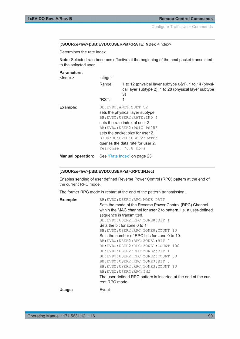
Remote-Control Commands1xEV-DO Rev. A/Rev. B
90Operating Manual 1171.5631.12 ─ 16
[:SOURce<hw>]:BB:EVDO:USER<st>:RATE:INDex <Index>
Determines the rate index.
Note: Selected rate becomes effective at the beginning of the next packet transmittedto the selected user.
Parameters:<Index> integer
Range: 1 to 12 (physical layer subtype 0&1), 1 to 14 (physi-cal layer subtype 2), 1 to 28 (physical layer subtype3)
*RST: 1
Example: BB:EVDO:ANET:SUBT S2sets the physical layer subtype.BB:EVDO:USER2:RATE:IND 4sets the rate index of user 2.BB:EVDO:USER2:PSIZ PS256sets the packet size for user 2.SOUR:BB:EVDO:USER2:RATE?queries the data rate for user 2.Response: 76.8 kbps
Manual operation: See "Rate Index" on page 23
[:SOURce<hw>]:BB:EVDO:USER<st>:RPC:INJect
Enables sending of user defined Reverse Power Control (RPC) pattern at the end ofthe current RPC mode.
The former RPC mode is restart at the end of the pattern transmission.
Example: BB:EVDO:USER2:RPC:MODE PATTSets the mode of the Reverse Power Control (RPC) Channelwithin the MAC channel for user 2 to pattern, i.e. a user-definedsequence is transmitted.BB:EVDO:USER2:RPC:ZONE0:BIT 1Sets the bit for zone 0 to 1BB:EVDO:USER2:RPC:ZONE0:COUNT 10Sets the number of RPC bits for zone 0 to 10.BB:EVDO:USER2:RPC:ZONE1:BIT 0BB:EVDO:USER2:RPC:ZONE1:COUNT 100BB:EVDO:USER2:RPC:ZONE2:BIT 1BB:EVDO:USER2:RPC:ZONE2:COUNT 50BB:EVDO:USER2:RPC:ZONE3:BIT 0BB:EVDO:USER2:RPC:ZONE3:COUNT 10BB:EVDO:USER2:RPC:INJThe user defined RPC pattern is inserted at the end of the cur-rent RPC mode.
Usage: Event
Configure Traffic User Commands
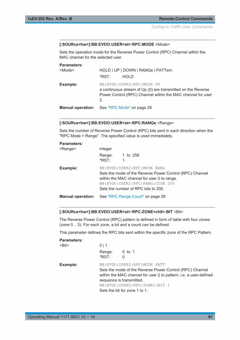
Remote-Control Commands1xEV-DO Rev. A/Rev. B
91Operating Manual 1171.5631.12 ─ 16
[:SOURce<hw>]:BB:EVDO:USER<st>:RPC:MODE <Mode>
Sets the operation mode for the Reverse Power Control (RPC) Channel within theMAC channel for the selected user.
Parameters:<Mode> HOLD | UP | DOWN | RANGe | PATTern
*RST: HOLD
Example: BB:EVDO:USER2:RPC:MODE UPa continuous stream of Up (0) are transmitted on the ReversePower Control (RPC) Channel within the MAC channel for user2.
Manual operation: See "RPC Mode" on page 28
[:SOURce<hw>]:BB:EVDO:USER<st>:RPC:RANGe <Range>
Sets the number of Reverse Power Control (RPC) bits sent in each direction when the"RPC Mode = Range". The specified value is used immediately.
Parameters:<Range> integer
Range: 1 to 256*RST: 1
Example: BB:EVDO:USER2:RPC:MODE RANGSets the mode of the Reverse Power Control (RPC) Channelwithin the MAC channel for user 2 to range.BB:EVDO:USER2:RPC:RANG:COUN 200Sets the number of RPC bits to 200.
Manual operation: See "RPC Range Count" on page 29
[:SOURce<hw>]:BB:EVDO:USER<st>:RPC:ZONE<ch0>:BIT <Bit>
The Reverse Power Control (RPC) pattern is defined in form of table with four zones(zone 0 .. 3). For each zone, a bit and a count can be defined.
This parameter defines the RPC bits sent within the specific zone of the RPC Pattern.
Parameters:<Bit> 0 | 1
Range: 0 to 1*RST: 0
Example: BB:EVDO:USER2:RPC:MODE PATTSets the mode of the Reverse Power Control (RPC) Channelwithin the MAC channel for user 2 to pattern, i.e. a user-definedsequence is transmitted.BB:EVDO:USER2:RPC:ZONE1:BIT 1Sets the bit for zone 1 to 1.
Configure Traffic User Commands

Remote-Control Commands1xEV-DO Rev. A/Rev. B
92Operating Manual 1171.5631.12 ─ 16
Manual operation: See "RPC Pattern" on page 29
[:SOURce<hw>]:BB:EVDO:USER<st>:RPC:ZONE<ch0>:COUNt <Count>
The Reverse Power Control (RPC) pattern is defined in form of table with four zones(zone 0 .. 3). For each zone, a bit and a count can be defined.
This parameter defines the number of RPC bits sent within the specific zone of theRPC Pattern.
Parameters:<Count> integer
Range: 1 to 128*RST: 0
Example: BB:EVDO:USER2:RPC:MODE PATTSets the mode of the Reverse Power Control (RPC) Channelwithin the MAC channel for user 2 to pattern, i.e. a user-definedsequence is transmitted.BB:EVDO:USER2:RPC:ZONE1:COUNT 10Sets the number of RPC bits for zone 1 to 10.
Manual operation: See "RPC Pattern" on page 29
[:SOURce<hw>]:BB:EVDO:USER<st>:SCOunt?
Queries the slot count of the packets sent to the selected user.
Return values: <SCount> integer
Example: BB:EVDO:ANET:SUBT S2Sets the physical layer subtype to 2.BB:EVDO:USER2:RATE:IND 4Sets the rate index of user 2 to 4.BB:EVDO:USER2:PSIZ PS256Sets the packet size for user 2 to 256.SOUR:BB:EVDO:USER2:SCO?Queries the number of slots for user 2.Response: 2
Usage: Query only
Manual operation: See "Slot Count" on page 27
[:SOURce<hw>]:BB:EVDO:USER<st>:STATe <State>
Enables or disables the selected user. If the user is enabled, the proper MAC Index isplaced within the MAC channel and packets can be sent to the user. If disabled, theMAC Index is not present within the MAC channel and packets cannot be sent to theuser.
Note: Disabling the state of a user during a transfer aborts all transfers to the user.
Configure Traffic User Commands
Remote-Control Commands1xEV-DO Rev. A/Rev. B
93Operating Manual 1171.5631.12 ─ 16
Parameters:<State> 0 | 1 | OFF | ON
*RST: ON (user 1); OFF (user 2 .. 4)
Example: BB:EVDO:USER2:STAT ONActivates user 2.
Manual operation: See "Configure Traffic Channels" on page 15
4.10 Configure Access Terminal Commands
[:SOURce<hw>]:BB:EVDO:PREDefined.............................................................................94[:SOURce<hw>]:BB:EVDO:TERMinal<st>:ACKChannel:GAIN..............................................95[:SOURce<hw>]:BB:EVDO:TERMinal<st>:ACKChannel:GATing...........................................95[:SOURce<hw>]:BB:EVDO:TERMinal<st>:ACKChannel:MODE............................................96[:SOURce<hw>]:BB:EVDO:TERMinal<st>:ACKChannel:STATe............................................96[:SOURce<hw>]:BB:EVDO:TERMinal<st>:ACKChannel:VALues.......................................... 97[:SOURce<hw>]:BB:EVDO:TERMinal<st>:ACYCle:DURation...............................................97[:SOURce<hw>]:BB:EVDO:TERMinal<st>:ACYCle:OFFSet................................................. 97[:SOURce<hw>]:BB:EVDO:TERMinal<st>:APCHannel:GAIN............................................... 98[:SOURce<hw>]:BB:EVDO:TERMinal<st>:APCHannel:PAYLoad:MINimum...........................98[:SOURce<hw>]:BB:EVDO:TERMinal<st>:APCHannel:STATe............................................. 98[:SOURce<hw>]:BB:EVDO:TERMinal<st>:DCHannel:CLENgth............................................ 99[:SOURce<hw>]:BB:EVDO:TERMinal<st>:DCHannel:DATA.................................................99[:SOURce<hw>]:BB:EVDO:TERMinal<st>:DCHannel:DATA:DSELection.............................100[:SOURce<hw>]:BB:EVDO:TERMinal<st>:DCHannel:DATA:PATTern.................................100[:SOURce<hw>]:BB:EVDO:TERMinal<st>:DCHannel:DRATe.............................................100[:SOURce<hw>]:BB:EVDO:TERMinal<st>:DCHannel:FCS[:STATe].................................... 101[:SOURce<hw>]:BB:EVDO:TERMinal<st>:DCHannel:GAIN............................................... 101[:SOURce<hw>]:BB:EVDO:TERMinal<st>:DCHannel:PACKet<ch>:CCODing......................101[:SOURce<hw>]:BB:EVDO:TERMinal<st>:DCHannel:PACKet<ch>:COUNt......................... 102[:SOURce<hw>]:BB:EVDO:TERMinal<st>:DCHannel:PACKet<ch>:DATA........................... 102[:SOURce<hw>]:BB:EVDO:TERMinal<st>:DCHannel:PACKet<ch>:DATA:DSELection......... 103[:SOURce<hw>]:BB:EVDO:TERMinal<st>:DCHannel:PACKet<ch>:DATA:PATTern............. 103[:SOURce<hw>]:BB:EVDO:TERMinal<st>:DCHannel:PACKet<ch>:DRATe?....................... 104[:SOURce<hw>]:BB:EVDO:TERMinal<st>:DCHannel:PACKet<ch>:FCS[:STATe]................ 104[:SOURce<hw>]:BB:EVDO:TERMinal<st>:DCHannel:PACKet<ch>:GAIN............................105[:SOURce<hw>]:BB:EVDO:TERMinal<st>:DCHannel:PACKet<ch>:INFinite.........................105[:SOURce<hw>]:BB:EVDO:TERMinal<st>:DCHannel:PACKet<ch>:MODulation?.................106[:SOURce<hw>]:BB:EVDO:TERMinal<st>:DCHannel:PACKet<ch>:PSIZe...........................106[:SOURce<hw>]:BB:EVDO:TERMinal<st>:DCHannel:PACKet<ch>:STATe..........................107[:SOURce<hw>]:BB:EVDO:TERMinal<st>:DCHannel:PACKet<ch>:SUBPackets[:COUNt].... 107[:SOURce<hw>]:BB:EVDO:TERMinal<st>:DCHannel:STATe............................................. 107[:SOURce<hw>]:BB:EVDO:TERMinal<st>:DQSPreading................................................... 108[:SOURce<hw>]:BB:EVDO:TERMinal<st>:DRCChannel:COVer......................................... 108[:SOURce<hw>]:BB:EVDO:TERMinal<st>:DRCChannel:GAIN........................................... 108[:SOURce<hw>]:BB:EVDO:TERMinal<st>:DRCChannel:GATing[:STATe]........................... 109[:SOURce<hw>]:BB:EVDO:TERMinal<st>:DRCChannel:LENGth........................................109[:SOURce<hw>]:BB:EVDO:TERMinal<st>:DRCChannel:STATe......................................... 109
Configure Access Terminal Commands
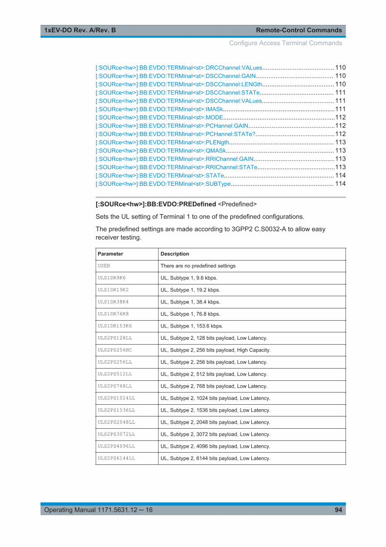
Remote-Control Commands1xEV-DO Rev. A/Rev. B
94Operating Manual 1171.5631.12 ─ 16
[:SOURce<hw>]:BB:EVDO:TERMinal<st>:DRCChannel:VALues........................................110[:SOURce<hw>]:BB:EVDO:TERMinal<st>:DSCChannel:GAIN........................................... 110[:SOURce<hw>]:BB:EVDO:TERMinal<st>:DSCChannel:LENGth........................................110[:SOURce<hw>]:BB:EVDO:TERMinal<st>:DSCChannel:STATe......................................... 111[:SOURce<hw>]:BB:EVDO:TERMinal<st>:DSCChannel:VALues........................................ 111[:SOURce<hw>]:BB:EVDO:TERMinal<st>:IMASk..............................................................111[:SOURce<hw>]:BB:EVDO:TERMinal<st>:MODE..............................................................112[:SOURce<hw>]:BB:EVDO:TERMinal<st>:PCHannel:GAIN................................................112[:SOURce<hw>]:BB:EVDO:TERMinal<st>:PCHannel:STATe?............................................112[:SOURce<hw>]:BB:EVDO:TERMinal<st>:PLENgth.......................................................... 113[:SOURce<hw>]:BB:EVDO:TERMinal<st>:QMASk............................................................ 113[:SOURce<hw>]:BB:EVDO:TERMinal<st>:RRIChannel:GAIN.............................................113[:SOURce<hw>]:BB:EVDO:TERMinal<st>:RRIChannel:STATe...........................................113[:SOURce<hw>]:BB:EVDO:TERMinal<st>:STATe............................................................. 114[:SOURce<hw>]:BB:EVDO:TERMinal<st>:SUBType......................................................... 114
[:SOURce<hw>]:BB:EVDO:PREDefined <Predefined>
Sets the UL setting of Terminal 1 to one of the predefined configurations.
The predefined settings are made according to 3GPP2 C.S0032-A to allow easyreceiver testing.
Parameter Description
USER There are no predefined settings
ULS1DR9K6 UL, Subtype 1, 9.6 kbps.
ULS1DR19K2 UL, Subtype 1, 19.2 kbps.
ULS1DR38K4 UL, Subtype 1, 38.4 kbps.
ULS1DR76K8 UL, Subtype 1, 76.8 kbps.
ULS1DR153K6 UL, Subtype 1, 153.6 kbps.
ULS2PS128LL UL, Subtype 2, 128 bits payload, Low Latency.
ULS2PS256HC UL, Subtype 2, 256 bits payload, High Capacity.
ULS2PS256LL UL, Subtype 2, 256 bits payload, Low Latency.
ULS2PS512LL UL, Subtype 2, 512 bits payload, Low Latency.
ULS2PS768LL UL, Subtype 2, 768 bits payload, Low Latency.
ULS2PS1024LL UL, Subtype 2, 1024 bits payload, Low Latency.
ULS2PS1536LL UL, Subtype 2, 1536 bits payload, Low Latency.
ULS2PS2048LL UL, Subtype 2, 2048 bits payload, Low Latency.
ULS2PS3072LL UL, Subtype 2, 3072 bits payload, Low Latency.
ULS2PS4096LL UL, Subtype 2, 4096 bits payload, Low Latency.
ULS2PS6144LL UL, Subtype 2, 6144 bits payload, Low Latency.
Configure Access Terminal Commands
Remote-Control Commands1xEV-DO Rev. A/Rev. B
95Operating Manual 1171.5631.12 ─ 16
Parameter Description
ULS2PS8192LL UL, Subtype 2, 8192 bits payload, Low Latency.
ULS2PS12288LL UL, Subtype 2, 12288 bits payload, Low Latency.
Parameters:<Predefined> USER | ULS1DR9K6 | ULS1DR19K2 | ULS1DR38K4 |
ULS1DR76K8 | ULS1DR153K6 | ULS2PS128LL |ULS2PS256HC | ULS2PS256LL | ULS2PS512LL |ULS2PS768LL | ULS2PS1024LL | ULS2PS1536LL |ULS2PS2048LL | ULS2PS3072LL | ULS2PS4096LL |ULS2PS6144LL | ULS2PS8192LL | ULS2PS12288LL*RST: USER
Example: BB:EVDO:PRED ULS2PS256HCSets the UL settings of Terminal 1 to UL of Subtype 2 with 256bits payload and High Capacity.BB:EVDO:TERM1:SUBT?Response: S2.BB:EVDO:TERM1:DCH:PACK1:PSIZ?Response: 256
Manual operation: See "Predefined Settings" on page 14
[:SOURce<hw>]:BB:EVDO:TERMinal<st>:ACKChannel:GAIN <Gain>
(enabled for access terminal working in traffic mode)
Sets the gain of the ACK channel relative to the pilot channel power.
Parameters:<Gain> float
Range: -80 to 30Increment: 0.01*RST: 0
Example: BB:EVDO:TERM2:ACKC:GAIN -10Sets the relative gain of ACK channel to -10 dB
Manual operation: See "Relative Gain (ACK Channel)" on page 37
[:SOURce<hw>]:BB:EVDO:TERMinal<st>:ACKChannel:GATing <Gating>
(enabled for access terminal working in traffic mode)
Sets the active and inactive slots of the ACK channel. This parameter is in binary for-mat and has a maximal length of 16 bits.
The sequence starts at frame 0 and slot 0 and is repeated with the length of the pat-tern. A 0 gates the ACK channel off for the corresponding slot, a 1 activates the chan-nel.
Configure Access Terminal Commands
Remote-Control Commands1xEV-DO Rev. A/Rev. B
96Operating Manual 1171.5631.12 ─ 16
Parameters:<Gating> integer
*RST: 0001
Example: BB:EVDO:TERM2:ACKC:GAT #B11001100,8Sets slots 3, 4, 7 and 8 of ACK channel as inactive.
Manual operation: See "Gating (bin) (ACK Channel)" on page 38
[:SOURce<hw>]:BB:EVDO:TERMinal<st>:ACKChannel:MODE <Mode>
(enabled for access terminal working in traffic mode)
Specifies the modulation mode of the ACK channel.
With BPSK modulation, a 0 (ACK) is mapped to +1 and a 1 (NAK) to -1.With OOKmodulation, a 0 (ACK) is mapped to ON and a 1 (NAK) to OFF.
Parameters:<Mode> BPSK | OOK
BPSKSets the modulation to BPSK (Binary Phase Shift Keying).OOKSets the modulation to OOK (On-Off Keying).Note: This value is only enabled for physical layer subtype 2.*RST: BPSK
Example: BB:EVDO:TERM2:MODE TRAFsets the mode of terminal 2 to traffic.BB:EVDO:TERM2:SUBT S2sets the physical layer subtype of terminal 2 to 2.BB:EVDO:TERM2:ACKC:MODE OOKselects OOK modulation for ACK channel of terminal 2.
Manual operation: See "Mode (ACK Channel)" on page 37
[:SOURce<hw>]:BB:EVDO:TERMinal<st>:ACKChannel:STATe <State>
(enabled for access terminal working in traffic mode)
Enables or disables the ACK channel.
Parameters:<State> 0 | 1 | OFF | ON
*RST: 1
Example: BB:EVDO:TERM2:ACKC:STAT OFFDeactivates the ACK channel for terminal 2.
Manual operation: See "State (ACK Channel)" on page 37
Configure Access Terminal Commands
Remote-Control Commands1xEV-DO Rev. A/Rev. B
97Operating Manual 1171.5631.12 ─ 16
[:SOURce<hw>]:BB:EVDO:TERMinal<st>:ACKChannel:VALues <Values>
(enabled for access terminal working in traffic mode)
Specifies the data pattern transmitted on the ACK Channel.
The sequence starts at frame 0 and slot 0 and is repeated with the length of the pat-tern.A 0 specifies an ACK, a 1 specifies a NAK. The pattern is only read for slots thatare gated on. This parameter is in binary format and has a maximal length of 16 bits.
Parameters:<Values> integer
*RST: #H1
Example: BB:EVDO:TERM2:ACKC:VAL #B011,3Sets the data pattern transmitted on the ACK channel for termi-nal 2.
Manual operation: See "Values (ACK Channel)" on page 38
[:SOURce<hw>]:BB:EVDO:TERMinal<st>:ACYCle:DURation <Duration>
(enabled for access terminal working in access mode)
Sets the access cycle duration in slots. Access probes are repeated with a period ofaccess cycle duration slots.
Parameters:<Duration> integer
Range: 1 to 255*RST: 16
Example: BB:EVDO:TERM2:MODE ACCenables terminal 2 to work in access mode.BB:EVDO:TERM2:ACYC:DUR 20sets the duration of the access cycle for terminal 2 to 20 slots.
Manual operation: See "Access Cycle Duration" on page 34
[:SOURce<hw>]:BB:EVDO:TERMinal<st>:ACYCle:OFFSet <Offset>
(enabled for access terminal working in access mode)
The Access Channel transmission starts with this number of slots relative to the begin-ning of each access cycle duration.
Parameters:<Offset> integer
Range: 0 to 12Increment: 4*RST: 0
Configure Access Terminal Commands
Remote-Control Commands1xEV-DO Rev. A/Rev. B
98Operating Manual 1171.5631.12 ─ 16
Example: BB:EVDO:TERM2:MODE ACCEnables terminal 2 to work in access mode.BB:EVDO:TERM2:ACYC:OFFS 10Sets the offset of the Access Channel to 10.
Manual operation: See "Access Cycle Offset" on page 34
[:SOURce<hw>]:BB:EVDO:TERMinal<st>:APCHannel:GAIN <Gain>
(enabled for Physical Layer subtype 2 and for an access terminal working in trafficmode)
Sets the gain of the auxiliary pilot channel relative to the data channel power.
Note: All other channel gains are specified relative to the pilot power, but the auxiliarypilot gain is specified relative to the data channel power.
Parameters:<Gain> float
Range: -80 to 30Increment: 0.01*RST: 0
Example: BB:EVDO:TERM2:APCH:GAIN -10sets the relative gain of auxiliary pilot channel to -10 dB
Manual operation: See "Relative Gain (Auxiliary Pilot Channel)" on page 35
[:SOURce<hw>]:BB:EVDO:TERMinal<st>:APCHannel:PAYLoad:MINimum<Minimum>
(enabled for Physical Layer subtype 2 and for an access terminal working in trafficmode)
Sets the minimum payload size in bits of the data channel that activates the transmis-sion of the auxiliary pilot channel.
Parameters:<Minimum> PS128 | PS256 | PS512 | PS768 | PS1024 | PS1536 | PS2048 |
PS3072 | PS4096 | PS6144 | PS8192 | PS12288*RST: PS128
Example: BB:EVDO:TERM2:APCH:PAYL:MIN PS256Sets the minimum payload of the auxiliary pilot channel to 256bits.
Manual operation: See "Minimum Payload (Auxiliary Pilot Channel)" on page 35
[:SOURce<hw>]:BB:EVDO:TERMinal<st>:APCHannel:STATe <State>
(enabled for Physical Layer subtype 2 and for an access terminal working in trafficmode)
Configure Access Terminal Commands
Remote-Control Commands1xEV-DO Rev. A/Rev. B
99Operating Manual 1171.5631.12 ─ 16
Enables or disables the auxiliary pilot channel.
Parameters:<State> 0 | 1 | OFF | ON
*RST: 1
Example: BB:EVDO:TERM2:APCH:STAT OFFDeactivates the auxiliary pilot channel for terminal 2.
Manual operation: See "State (Auxiliary Pilot Channel)" on page 34
[:SOURce<hw>]:BB:EVDO:TERMinal<st>:DCHannel:CLENgth <CLength>
(enabled for access terminal working in access mode)
Sets the number of frames (16 slots each) to be transmitted after the preamble. Eachframe contains one data packet.
Parameters:<CLength> integer
Range: 1 to 15*RST: 1
Example: BB:EVDO:TERM2:MODE ACCEnables terminal 2 to work in access mode.BB:EVDO:TERM2:DCH:CLEN 10For terminal two, ten frames will be transmitted after the pream-ble.
Manual operation: See "Capsule Length (Data Channel)" on page 43
[:SOURce<hw>]:BB:EVDO:TERMinal<st>:DCHannel:DATA <Data>
Selects the data source, e.g. a sequence of 0 or 1, a pseudo-random sequence withdifferent length, a pattern or a data list (DLISt).
Parameters:<Data> ZERO | ONE | PATTern | PN9 | PN11 | PN15 | PN16 | PN20 |
PN21 | PN23 | DLISt*RST: PN9
Example: SOURce:BB:EVDO:TERMinal2:DCHannel:DATA PATTernSets the data source of terminal 2 to pattern.SOURce:BB:EVDO:TERMinal2:DCHannel:DATA:PATTern#H3F,8Sets the pattern for the data source of terminal 2.
Configure Access Terminal Commands
Remote-Control Commands1xEV-DO Rev. A/Rev. B
100Operating Manual 1171.5631.12 ─ 16
Example: SOURce:BB:EVDO:TERMinal2:DCHannel:DATA DLIStSets the data source of terminal 2 to data list.MMEM:CDIR "datalists"Selects the directory for the data lists.SOURce:BB:EVDO:TERMinal2:DCHannel:DATA:DSELection "datalist.dm_iqd"Selects datalist.dm_iqd file as data source. This file mustbe in the directory <root>datalists and have a file extension*.dm_iqd.
Manual operation: See "Data List Management" on page 13
[:SOURce<hw>]:BB:EVDO:TERMinal<st>:DCHannel:DATA:DSELection<Filename>
Selects the data list for the data source.
Parameters:<Filename> string
Example: see [:SOURce<hw>]:BB:EVDO:TERMinal<st>:DCHannel:DATA on page 99
Manual operation: See "Data List Management" on page 13
[:SOURce<hw>]:BB:EVDO:TERMinal<st>:DCHannel:DATA:PATTern <Pattern>
Selects the bit pattern for the data source.
Parameters:<Pattern> 64 bits
Example: see [:SOURce<hw>]:BB:EVDO:TERMinal<st>:DCHannel:DATA on page 99
Manual operation: See "Data Source (Data Channel)" on page 43
[:SOURce<hw>]:BB:EVDO:TERMinal<st>:DCHannel:DRATe <DRate>
(enabled for an access terminal working in access mode)
Selects the data rate for the Data Channel.
Parameters:<DRate> DR4K8 | DR9K6 | DR19K2 | DR38K4 | DR76K8 | DR153K6 |
DR307K2 | DR614K4 | DR921K6 | DR1228K8 | DR1536K |DR1843K2 | DR2457K6 | DR3072K | DR460K8 | DR768K |DR1075K2 | DR2150K4 | DR3686K4 | DR4300K8 | DR4915K2*RST: DR9K6
Configure Access Terminal Commands
Remote-Control Commands1xEV-DO Rev. A/Rev. B
101Operating Manual 1171.5631.12 ─ 16
Example: BB:EVDO:TERM2:MODE ACCEnables terminal 2 to work in access mode.BB:EVDO:TERM2:DCH:DRAT DR19K2Sets the data rate of the data channel for terminal 2 kbps to 19.2kbps.
Manual operation: See "Data Rate (Data Channel)" on page 43
[:SOURce<hw>]:BB:EVDO:TERMinal<st>:DCHannel:FCS[:STATe] <State>
(enabled for an access terminal working in access mode)
Enables or disables appending a standard frame check sequence (FCS) to the MAClayer packet.
Parameters:<State> 0 | 1 | OFF | ON
*RST: 1
Example: BB:EVDO:TERM2:MODE ACCEnables terminal 2 to work in access mode.BB:EVDO:TERM2:DCH:FCS:STAT OFFDisables appending of FCS to the MAC layer for terminal 2.
Manual operation: See "Append FCS (Data Channel)" on page 44
[:SOURce<hw>]:BB:EVDO:TERMinal<st>:DCHannel:GAIN <Gain>
(enabled for an access terminal working in access mode)
Sets the gain in dB of the data channel relative to the pilot channel power.
Parameters:<Gain> float
Range: -80 to 30Increment: 0.01*RST: 0
Example: BB:EVDO:TERM2:MODE ACCEnables terminal 2 to work in access mode.BB:EVDO:TERM2:DCH:GAIN -10Sets the relative gain of data channel to -10 dB
Manual operation: See "Relative Gain (Data Channel)" on page 43
[:SOURce<hw>]:BB:EVDO:TERMinal<st>:DCHannel:PACKet<ch>:CCODing<CCoding>
(enabled for an access terminal working in traffic mode)
Activates or deactivates channel coding, including scrambling, turbo encoding andchannel interleaving.
Configure Access Terminal Commands
Remote-Control Commands1xEV-DO Rev. A/Rev. B
102Operating Manual 1171.5631.12 ─ 16
Parameters:<CCoding> 0 | 1 | OFF | ON
*RST: 1
Example: BB:EVDO:TERM2:MODE TRAFEnables terminal 2 to work in traffic mode.BB:EVDO:TERM2:SUBT S2Sets physical layer subtype 2 for terminal 2.BB:EVDO:TERM2:DCH:PACK3:CCOD OFFDisables channel coding for packet 3.
Manual operation: See "Channel Coding (Packet)" on page 41
[:SOURce<hw>]:BB:EVDO:TERMinal<st>:DCHannel:PACKet<ch>:COUNt<Count>
(enabled for an access terminal working in traffic mode)
Sets the number of packets to be sent.
The number of packets to be send depends on whether the parameter "Infinite Pack-ets" is enabled or disabled. If "Infinite Packets "is enabled, there is no limit to the num-ber of packets sent.
If "Infinite Packets" is disabled, the number of packets can be specified. In this case,the data channel will be switched off after the specified number of packets have beensent.
Note: Configuration of Packet 2 and Packet 3 transmitted on the second and the thirdsubframe, is only enabled for physical layer subtype 2.
Parameters:<Count> integer
Range: 0 to 65536*RST: 65536
Example: BB:EVDO:TERM2:MODE TRAFEnables terminal 2 to work in traffic mode.BB:EVDO:TERM2:SUBT S2Sets physical layer subtype 2 for terminal 2.BB:EVDO:TERM2:DCH:PACK3:INF OFFDisables sending of unlimited umber of packets.BB:EVDO:TERM2:DCH:PACK3:COUN 2000Sets number of packets to be sent to 2000.
Manual operation: See "Number of Packets to Send (Packet)" on page 40
[:SOURce<hw>]:BB:EVDO:TERMinal<st>:DCHannel:PACKet<ch>:DATA <Data>
Selects the data source of an access terminal working in traffic mode
Configure Access Terminal Commands
Remote-Control Commands1xEV-DO Rev. A/Rev. B
103Operating Manual 1171.5631.12 ─ 16
Parameters:<Data> ZERO | ONE | PATTern | PN9 | PN11 | PN15 | PN16 | PN20 |
PN21 | PN23 | DLISt*RST: PN9
Example: SOURce:BB:EVDO:TERMinal2:MODE TRAFficEnables terminal 2 to work in traffic mode.SOURce:BB:EVDO:TERMinal2:SUBType S2Sets physical layer subtype 2 for terminal 2.SOURce:BB:EVDO:TERMinal2:DCHannel:PACKet3:DATAPATTernSets the data source of terminal 2 to pattern.SOURce:BB:EVDO:TERMinal2:DCHannel:PACKet3:PATTern #H3F,8Sets the pattern for the data source of terminal 2.
Example: SOURce:BB:EVDO:TERMinal2:DCHannel:PACKet1:DATADLIStSets the data source of terminal 2, packet 1 to data list.MMEM:CDIR "<root>datalists"Selects the directory for the data lists.SOURce:BB:EVDO:TERMinal2:DCHannel:PACKet1:DATA:DSELection "datalist.dm_iqd"Selects datalist.dm_iqd file as data source. This file mustbe in the directory <root>datalists and have a file extension*.dm_iqd.
Manual operation: See "Data List Management" on page 13
[:SOURce<hw>]:BB:EVDO:TERMinal<st>:DCHannel:PACKet<ch>:DATA:DSELection <Filename>
(enabled for an access terminal working in traffic mode)
Selects the data list for the data source.
Parameters:<Filename> string
Example: See [:SOURce<hw>]:BB:EVDO:TERMinal<st>:DCHannel:PACKet<ch>:DATA on page 102
Manual operation: See "Data List Management" on page 13
[:SOURce<hw>]:BB:EVDO:TERMinal<st>:DCHannel:PACKet<ch>:DATA:PATTern <Pattern>
(enabled for an access terminal working in traffic mode)
Selects the bit pattern for the data source.
Note: Configuration of Packet 2 and Packet 3 transmitted on the second and the thirdsubframe, is only enabled for physical layer subtype 2.
Configure Access Terminal Commands
Remote-Control Commands1xEV-DO Rev. A/Rev. B
104Operating Manual 1171.5631.12 ─ 16
Parameters:<Pattern> 64 bits
Example: see [:SOURce<hw>]:BB:EVDO:TERMinal<st>:DCHannel:PACKet<ch>:DATA on page 102
Manual operation: See "Data Source (Packet)" on page 41
[:SOURce<hw>]:BB:EVDO:TERMinal<st>:DCHannel:PACKet<ch>:DRATe?
(enabled for an access terminal working in traffic mode)
Displays the data rate in kbps of the selected packet.
Note: Configuration of Packet 2 and Packet 3 transmitted on the second and the thirdsubframe, is only enabled for physical layer subtype 2.
Return values: <DRate> float
Range: 0 to ...
Example: BB:EVDO:TERM2:MODE TRAFenables terminal 2 to work in traffic mode.BB:EVDO:TERM2:DCH:PACK2:DRAT?queries the data rate of the packet number 2 for terminal 2.Response: '6.4'the data rate of packet 2 is 6.4 kbps.
Usage: Query only
Manual operation: See "Data Rate (Packet)" on page 41
[:SOURce<hw>]:BB:EVDO:TERMinal<st>:DCHannel:PACKet<ch>:FCS[:STATe]<State>
(enabled for an access terminal working in traffic mode)
Enables or disables appending a standard Frame Check Sequence (FCS) and tail tothe MAC layer packet.
Note: Configuration of Packet 2 and Packet 3 transmitted on the second and the thirdsubframe, is only enabled for physical layer subtype 2.
Parameters:<State> 0 | 1 | OFF | ON
*RST: ON
Example: BB:EVDO:TERM2:MODE ACCenables terminal 2 to work in access mode.BB:EVDO:TERM2:DCH:PACK:FCS:STAT OFFdisables appending of FCS to the MAC layer for terminal 2,packet 1.
Manual operation: See "FCS (Packet)" on page 42
Configure Access Terminal Commands

Remote-Control Commands1xEV-DO Rev. A/Rev. B
105Operating Manual 1171.5631.12 ─ 16
[:SOURce<hw>]:BB:EVDO:TERMinal<st>:DCHannel:PACKet<ch>:GAIN <Gain>
(enabled for an access terminal working in traffic mode)
Sets the gain in dB of the Data Channel relative to the pilot channel power.
Note: Configuration of Packet 2 and Packet 3 transmitted on the second and the thirdsubframe, is only enabled for physical layer subtype 2.
Parameters:<Gain> float
Range: -80 to 30Increment: 0.01*RST: 0
Example: BB:EVDO:TERM2:MODE TRAFEnables terminal 2 to work in traffic mode.BB:EVDO:TERM2:SUBT S2Sets the physical layer subtype of terminal 2 to 2.BB:EVDO:TERM2:DCH:PACK3:GAIN -10Sets the relative gain of packet 3 dB to -10 dB
Manual operation: See "Relative Gain (Packet)" on page 39
[:SOURce<hw>]:BB:EVDO:TERMinal<st>:DCHannel:PACKet<ch>:INFinite<Infinite>
(enabled for an access terminal working in traffic mode)
Enables or disables sending an unlimited number of packets.
The parameter "Number of Packets to be Send" depends on whether the parameter"Infinite Packets" is enabled or disabled. If "Infinite Packets" is enabled, there is no limitto the number of packets sent.
If "Infinite Packets" is disabled, the number of packets can be specified.
Note: Configuration of Packet 2 and Packet 3 transmitted on the second and the thirdsubframe, is only enabled for physical layer subtype 2.
Parameters:<Infinite> 0 | 1 | OFF | ON
*RST: ON
Example: BB:EVDO:TERM2:MODE TRAFEnables terminal 2 to work in traffic mode.BB:EVDO:TERM2:SUBT S2Sets physical layer subtype 2 for terminal 2.BB:EVDO:TERM2:DCH:PACK3:INF OFFDisables sending of unlimited umber of packets.BB:EVDO:TERM2:DCH:PACK3:COUN 2000Sets number of packets to be sent to 2000.
Manual operation: See "Infinite Packets (Packet)" on page 39
Configure Access Terminal Commands
Remote-Control Commands1xEV-DO Rev. A/Rev. B
106Operating Manual 1171.5631.12 ─ 16
[:SOURce<hw>]:BB:EVDO:TERMinal<st>:DCHannel:PACKet<ch>:MODulation?
(enabled for physical layer subtype 2 and for an access terminal working in trafficmode)
Displays the modulation type per packet.
Return values: <Modulation> B4 | Q4 | Q2 | Q4Q2 | E4E2
B4The modulation type is set to BPSK modulation with 4-ary Walshcover.Q4The modulation type is set to QPSK modulation with 4-aryWalsh cover.Q2The modulation type is set to QPSK modulation with 2-aryWalsh cover.Q4Q2Sum of Q4 and Q2 modulated symbols.E4E2Sum of E4 (8-PSK modulated with 4-ary Walsh cover) and E2(8-PSK modulated with 2-ary Walsh cover) modulated symbols.*RST: B4
Example: BB:EVDO:TERM2:DCH:PACK3:MOD?queries the modulation for packet 3 of terminal 2.
Usage: Query only
Manual operation: See "Modulation (Packet)" on page 40
[:SOURce<hw>]:BB:EVDO:TERMinal<st>:DCHannel:PACKet<ch>:PSIZe <PSize>
(enabled for an access terminal working in traffic mode)
Sets the Payload Size in bits for the selected packet.
Note: Configuration of Packet 2 and Packet 3 transmitted on the second and the thirdsubframe, is only enabled for physical layer subtype 2.
Parameters:<PSize> PS128 | PS256 | PS512 | PS768 | PS1024 | PS1536 | PS2048 |
PS3072 | PS4096 | PS6144 | PS8192 | PS12288
Example: BB:EVDO:TERM2:MODE TRAFenables terminal 2 to work in traffic mode.BB:EVDO:TERM2:SUBT S2sets the physical layer subtype of terminal 2 to 2.BB:EVDO:TERM2:DCH:PACK3:PSIZ PS512sets the payload size fro packet 3 to 512.
Manual operation: See "Payload Size (Packet)" on page 40
Configure Access Terminal Commands

Remote-Control Commands1xEV-DO Rev. A/Rev. B
107Operating Manual 1171.5631.12 ─ 16
[:SOURce<hw>]:BB:EVDO:TERMinal<st>:DCHannel:PACKet<ch>:STATe <State>
For an access terminal working in traffic mode, enables or disables the state of thepackets.
Parameters:<State> 0 | 1 | OFF | ON
*RST: 1
Example: BB:EVDO:TERM2:MODE TRAFEnables terminal 2 to work in traffic mode.BB:EVDO:TERM2:SUBT S2Sets the physical layer subtype of terminal 2 to 2.BB:EVDO:TERM2:DCH:PACK2:STAT OFFDeactivates packet 2 of terminal 2.
Manual operation: See "State (Packet)" on page 38
[:SOURce<hw>]:BB:EVDO:TERMinal<st>:DCHannel:PACKet<ch>:SUBPackets[:COUNt] <Count>
(enabled for physical layer subtype 2 and for an access terminal working in trafficmode)
Sets the number of subpackets to be sent.
Parameters:<Count> integer
Range: 1 to 4*RST: 1
Example: BB:EVDO:TERM2:MODE TRAFEnables terminal 2 to work in traffic mode.BB:EVDO:TERM2:SUBT S2Sets physical layer subtype 2 for terminal 2.BB:EVDO:TERM2:DCH:PACK3:SUBP:COUN 4Sets the number of subpackets to 4, i.e. subpacket 0, 1, 2 and 3of a packet is sent in a subframe each (with two subframes inter-leaving between). Afterward the next packet is started.This is to simulate a situation where three times NAK has beenreceived from the base station with an ACK after the fourth sub-packet
Manual operation: See "Number of Subpackets (Packet)" on page 40
[:SOURce<hw>]:BB:EVDO:TERMinal<st>:DCHannel:STATe <State>
(enabled for an access terminal working in access mode)
Enables or disables the state of the Data Channel.
Configure Access Terminal Commands

Remote-Control Commands1xEV-DO Rev. A/Rev. B
108Operating Manual 1171.5631.12 ─ 16
Parameters:<State> 0 | 1 | OFF | ON
*RST: ON
Example: BB:EVDO:TERM2:MODE ACCenables terminal 2 to work in access mode.BB:EVDO:TERM2:DCH:STAT OFFdisables data channel for terminal 2.
Manual operation: See "State (Data Channel)" on page 42
[:SOURce<hw>]:BB:EVDO:TERMinal<st>:DQSPreading <DqSpreading>
Disables the quadrature spreading (complex multiply) with PN sequences and longcode.
Parameters:<DqSpreading> 0 | 1 | OFF | ON
*RST: OFF
Example: BB:EVDO:TERM2:DQSP ONenables using quadrature spreading with PN sequence and longcode.
Manual operation: See "Disable Quadrature Spreading" on page 33
[:SOURce<hw>]:BB:EVDO:TERMinal<st>:DRCChannel:COVer <Cover>
(enabled for an access terminal working in traffic mode)
Selects the Data Rate Control (DRC) Channel Walsh cover.
Parameters:<Cover> integer
Range: 0 to 7*RST: 7
Example: BB:EVDO:TERM2:DRCC:COV 1Sets the DRC cover to 1.
Manual operation: See "Cover (DRC Channel)" on page 37
[:SOURce<hw>]:BB:EVDO:TERMinal<st>:DRCChannel:GAIN <Gain>
(enabled for an access terminal working in traffic mode)
Sets the gain of the Data Rate Control (DRC) channel relative to the pilot channelpower.
Configure Access Terminal Commands

Remote-Control Commands1xEV-DO Rev. A/Rev. B
109Operating Manual 1171.5631.12 ─ 16
Parameters:<Gain> float
Range: -80 dB to 10 dBIncrement: -*RST: 0 dB
Example: BB:EVDO:TERM2:DRCC:GAIN 10sets the relative gain for DRC to 10 dB.
Manual operation: See "Relative Gain (DRC Channel)" on page 36
[:SOURce<hw>]:BB:EVDO:TERMinal<st>:DRCChannel:GATing[:STATe] <State>
(enabled for an access terminal working in traffic mode)
Activates or deactivates the Data Rate Control (DRC) Channel gating.
If gating is active, each value of the DRC channel is transmitted for one slot followedby DRCLenght-1 empty slots.
With deactivated gating, each DRC value is repeated for DRC length slots.
Parameters:<State> 0 | 1 | OFF | ON
*RST: ON
Example: BB:EVDO:TERM2:DRCC:GAT:STAT OFFdeactivates DRC gating.
Manual operation: See "Gating Active (DRC Channel)" on page 37
[:SOURce<hw>]:BB:EVDO:TERMinal<st>:DRCChannel:LENGth <Length>
(enabled for an access terminal working in traffic mode)
Specifies the transmission duration of the Data Rate Control (DRC) channel in slots.
Parameters:<Length> DL1 | DL2 | DL4 | DL8
*RST: DL1
Example: BB:EVDO:TERM2:DRCC:LENG DL2Sets the transmission duration of DRC to two slots.
Manual operation: See "Length (DRC Channel)" on page 36
[:SOURce<hw>]:BB:EVDO:TERMinal<st>:DRCChannel:STATe <State>
(enabled for an access terminal working in traffic mode)
Enables or disables the state of the Data Rate Control (DRC) channel.
Configure Access Terminal Commands
Remote-Control Commands1xEV-DO Rev. A/Rev. B
110Operating Manual 1171.5631.12 ─ 16
Parameters:<State> 0 | 1 | OFF | ON
*RST: ON
Example: BB:EVDO:TERM2:DRCC:STAT OFFdeactivates DRC channel.
Manual operation: See "State (DRC Channel)" on page 36
[:SOURce<hw>]:BB:EVDO:TERMinal<st>:DRCChannel:VALues <Values>
(enabled for an access terminal working in traffic mode)
Specifies the pattern transmitted on the Data Rate Control (DRC) Channel. Thesequence starts at frame 0 and slot 0 and is repeated with the length of the pattern.Each specified value is used for DRC length slots.
Parameters:<Values> integer
*RST: #H0
Example: BB:EVDO:TERM2:DRCC:VAL #H7,4sets transmitted pattern on DRC to #H7,4.
Manual operation: See "Values (hex) (DRC Channel)" on page 36
[:SOURce<hw>]:BB:EVDO:TERMinal<st>:DSCChannel:GAIN <Gain>
(enabled for Physical Layer subtype 2 and for an access terminal working in trafficmode)
Sets the gain of the Data Source Control (DSC) channel relative to the pilot channelpower.
Parameters:<Gain> float
Range: -80 dB to 10 dBIncrement: -*RST: 0 dB
Example: BB:EVDO:TERM2:DSCC:GAIN 10sets the relative gain for DSC to 10 dB.
Manual operation: See "Relative Gain (DSC Channel)" on page 35
[:SOURce<hw>]:BB:EVDO:TERMinal<st>:DSCChannel:LENGth <Length>
(enabled for Physical Layer subtype 2 and for an access terminal working in trafficmode)
Specifies the transmission duration of the Data Source Control (DSC) channel in slots.
Configure Access Terminal Commands
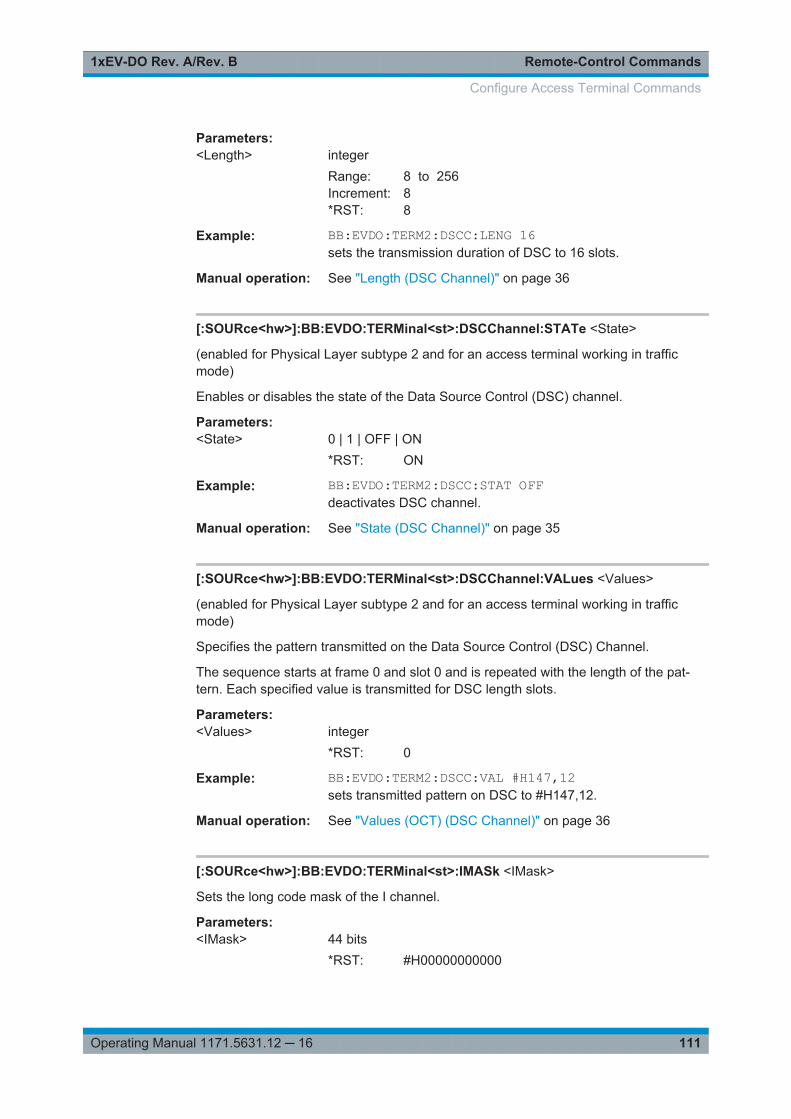
Remote-Control Commands1xEV-DO Rev. A/Rev. B
111Operating Manual 1171.5631.12 ─ 16
Parameters:<Length> integer
Range: 8 to 256Increment: 8*RST: 8
Example: BB:EVDO:TERM2:DSCC:LENG 16sets the transmission duration of DSC to 16 slots.
Manual operation: See "Length (DSC Channel)" on page 36
[:SOURce<hw>]:BB:EVDO:TERMinal<st>:DSCChannel:STATe <State>
(enabled for Physical Layer subtype 2 and for an access terminal working in trafficmode)
Enables or disables the state of the Data Source Control (DSC) channel.
Parameters:<State> 0 | 1 | OFF | ON
*RST: ON
Example: BB:EVDO:TERM2:DSCC:STAT OFFdeactivates DSC channel.
Manual operation: See "State (DSC Channel)" on page 35
[:SOURce<hw>]:BB:EVDO:TERMinal<st>:DSCChannel:VALues <Values>
(enabled for Physical Layer subtype 2 and for an access terminal working in trafficmode)
Specifies the pattern transmitted on the Data Source Control (DSC) Channel.
The sequence starts at frame 0 and slot 0 and is repeated with the length of the pat-tern. Each specified value is transmitted for DSC length slots.
Parameters:<Values> integer
*RST: 0
Example: BB:EVDO:TERM2:DSCC:VAL #H147,12sets transmitted pattern on DSC to #H147,12.
Manual operation: See "Values (OCT) (DSC Channel)" on page 36
[:SOURce<hw>]:BB:EVDO:TERMinal<st>:IMASk <IMask>
Sets the long code mask of the I channel.
Parameters:<IMask> 44 bits
*RST: #H00000000000
Configure Access Terminal Commands

Remote-Control Commands1xEV-DO Rev. A/Rev. B
112Operating Manual 1171.5631.12 ─ 16
Example: BB:EVDO:TERM2:IMAS #H2FFFFFFFFFFF,42sets the long code mask for I channel to #H2FFFFFFFFFFF,42.
Manual operation: See "Long Code Mask I (hex)" on page 33
[:SOURce<hw>]:BB:EVDO:TERMinal<st>:MODE <Mode>
Sets the mode (Traffic or Access) of the selected access terminal.
Parameters:<Mode> ACCess | TRAFfic
*RST: TRAFfic
Example: BB:EVDO:TERM2:MODE ACCsets the mode of terminal 2 to access.
Manual operation: See "Mode (Access Terminal)" on page 33
[:SOURce<hw>]:BB:EVDO:TERMinal<st>:PCHannel:GAIN <Gain>
Sets the gain of the pilot channel.
Gains of other channels are relative to the Pilot Channel power.
This setting is used to distinguish the power between access terminals, when morethan one access terminal is active.
Parameters:<Gain> float
Range: -80 to 10 dBIncrement: 0.01*RST: 0 dB
Example: BB:EVDO:TERM2:PCH:GAIN 10sets the gain of pilot channel to 10 dB.
Manual operation: See "Gain (Pilot Channel)" on page 34
[:SOURce<hw>]:BB:EVDO:TERMinal<st>:PCHannel:STATe?
Displays the state of the pilot channel.
Note: The pilot channel is always switched on.
Return values: <State> 0 | 1 | OFF | ON
*RST: ON
Example: BB:EVDO:TERM2:PCH:STAT?queries the state of the pilot channel.
Usage: Query only
Manual operation: See "State (Pilot Channel)" on page 34
Configure Access Terminal Commands
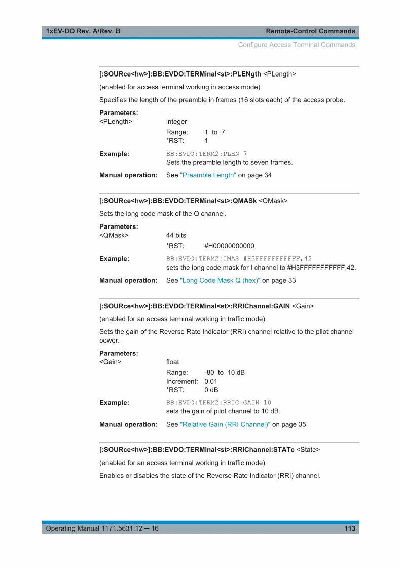
Remote-Control Commands1xEV-DO Rev. A/Rev. B
113Operating Manual 1171.5631.12 ─ 16
[:SOURce<hw>]:BB:EVDO:TERMinal<st>:PLENgth <PLength>
(enabled for access terminal working in access mode)
Specifies the length of the preamble in frames (16 slots each) of the access probe.
Parameters:<PLength> integer
Range: 1 to 7*RST: 1
Example: BB:EVDO:TERM2:PLEN 7Sets the preamble length to seven frames.
Manual operation: See "Preamble Length" on page 34
[:SOURce<hw>]:BB:EVDO:TERMinal<st>:QMASk <QMask>
Sets the long code mask of the Q channel.
Parameters:<QMask> 44 bits
*RST: #H00000000000
Example: BB:EVDO:TERM2:IMAS #H3FFFFFFFFFFF,42sets the long code mask for I channel to #H3FFFFFFFFFFF,42.
Manual operation: See "Long Code Mask Q (hex)" on page 33
[:SOURce<hw>]:BB:EVDO:TERMinal<st>:RRIChannel:GAIN <Gain>
(enabled for an access terminal working in traffic mode)
Sets the gain of the Reverse Rate Indicator (RRI) channel relative to the pilot channelpower.
Parameters:<Gain> float
Range: -80 to 10 dBIncrement: 0.01*RST: 0 dB
Example: BB:EVDO:TERM2:RRIC:GAIN 10sets the gain of pilot channel to 10 dB.
Manual operation: See "Relative Gain (RRI Channel)" on page 35
[:SOURce<hw>]:BB:EVDO:TERMinal<st>:RRIChannel:STATe <State>
(enabled for an access terminal working in traffic mode)
Enables or disables the state of the Reverse Rate Indicator (RRI) channel.
Configure Access Terminal Commands
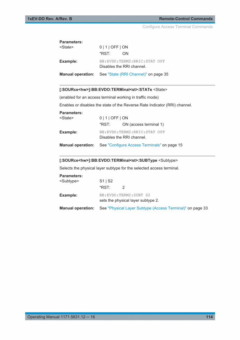
Remote-Control Commands1xEV-DO Rev. A/Rev. B
114Operating Manual 1171.5631.12 ─ 16
Parameters:<State> 0 | 1 | OFF | ON
*RST: ON
Example: BB:EVDO:TERM2:RRIC:STAT OFFDisables the RRI channel.
Manual operation: See "State (RRI Channel)" on page 35
[:SOURce<hw>]:BB:EVDO:TERMinal<st>:STATe <State>
(enabled for an access terminal working in traffic mode)
Enables or disables the state of the Reverse Rate Indicator (RRI) channel.
Parameters:<State> 0 | 1 | OFF | ON
*RST: ON (access terminal 1)
Example: BB:EVDO:TERM2:RRIC:STAT OFFDisables the RRI channel.
Manual operation: See "Configure Access Terminals" on page 15
[:SOURce<hw>]:BB:EVDO:TERMinal<st>:SUBType <Subtype>
Selects the physical layer subtype for the selected access terminal.
Parameters:<Subtype> S1 | S2
*RST: 2
Example: BB:EVDO:TERM2:SUBT S2sets the physical layer subtype 2.
Manual operation: See "Physical Layer Subtype (Access Terminal)" on page 33
Configure Access Terminal Commands
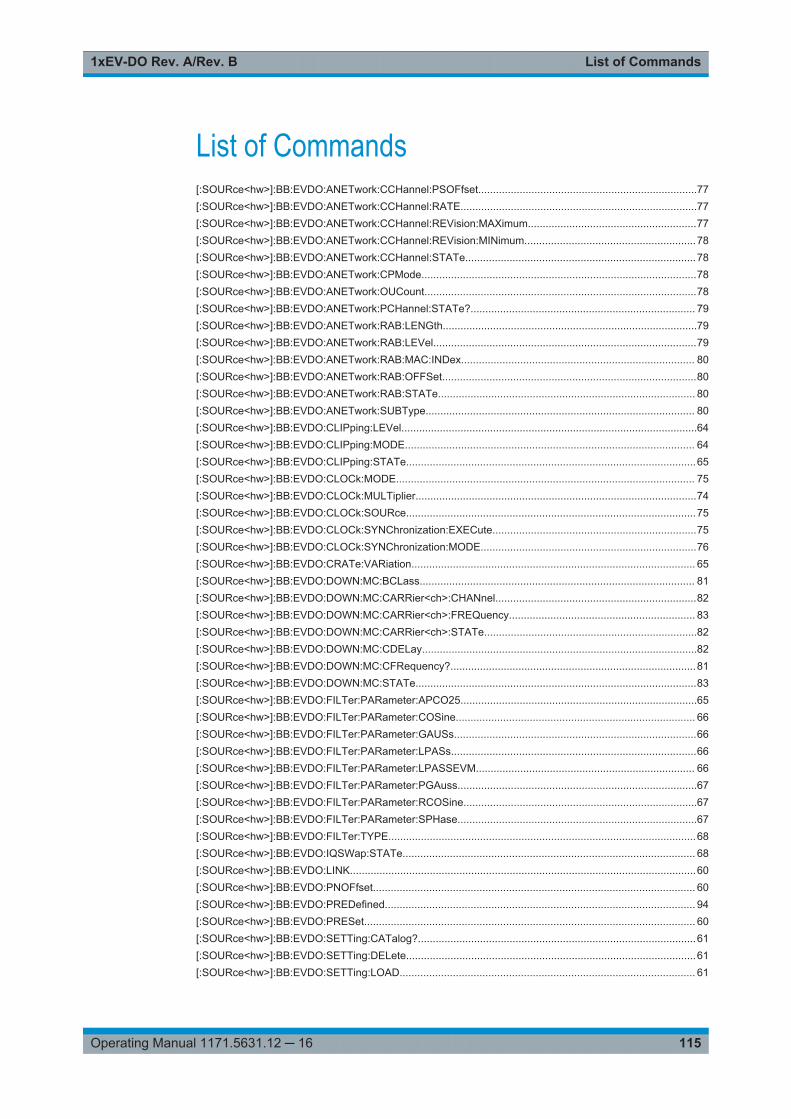
List of Commands1xEV-DO Rev. A/Rev. B
115Operating Manual 1171.5631.12 ─ 16
List of Commands[:SOURce<hw>]:BB:EVDO:ANETwork:CCHannel:PSOFfset..........................................................................77[:SOURce<hw>]:BB:EVDO:ANETwork:CCHannel:RATE................................................................................77[:SOURce<hw>]:BB:EVDO:ANETwork:CCHannel:REVision:MAXimum.........................................................77[:SOURce<hw>]:BB:EVDO:ANETwork:CCHannel:REVision:MINimum..........................................................78[:SOURce<hw>]:BB:EVDO:ANETwork:CCHannel:STATe..............................................................................78[:SOURce<hw>]:BB:EVDO:ANETwork:CPMode.............................................................................................78[:SOURce<hw>]:BB:EVDO:ANETwork:OUCount............................................................................................78[:SOURce<hw>]:BB:EVDO:ANETwork:PCHannel:STATe?............................................................................ 79[:SOURce<hw>]:BB:EVDO:ANETwork:RAB:LENGth......................................................................................79[:SOURce<hw>]:BB:EVDO:ANETwork:RAB:LEVel.........................................................................................79[:SOURce<hw>]:BB:EVDO:ANETwork:RAB:MAC:INDex............................................................................... 80[:SOURce<hw>]:BB:EVDO:ANETwork:RAB:OFFSet......................................................................................80[:SOURce<hw>]:BB:EVDO:ANETwork:RAB:STATe....................................................................................... 80[:SOURce<hw>]:BB:EVDO:ANETwork:SUBType........................................................................................... 80[:SOURce<hw>]:BB:EVDO:CLIPping:LEVel....................................................................................................64[:SOURce<hw>]:BB:EVDO:CLIPping:MODE.................................................................................................. 64[:SOURce<hw>]:BB:EVDO:CLIPping:STATe..................................................................................................65[:SOURce<hw>]:BB:EVDO:CLOCk:MODE..................................................................................................... 75[:SOURce<hw>]:BB:EVDO:CLOCk:MULTiplier...............................................................................................74[:SOURce<hw>]:BB:EVDO:CLOCk:SOURce..................................................................................................75[:SOURce<hw>]:BB:EVDO:CLOCk:SYNChronization:EXECute.....................................................................75[:SOURce<hw>]:BB:EVDO:CLOCk:SYNChronization:MODE.........................................................................76[:SOURce<hw>]:BB:EVDO:CRATe:VARiation................................................................................................ 65[:SOURce<hw>]:BB:EVDO:DOWN:MC:BCLass............................................................................................. 81[:SOURce<hw>]:BB:EVDO:DOWN:MC:CARRier<ch>:CHANnel....................................................................82[:SOURce<hw>]:BB:EVDO:DOWN:MC:CARRier<ch>:FREQuency............................................................... 83[:SOURce<hw>]:BB:EVDO:DOWN:MC:CARRier<ch>:STATe........................................................................82[:SOURce<hw>]:BB:EVDO:DOWN:MC:CDELay.............................................................................................82[:SOURce<hw>]:BB:EVDO:DOWN:MC:CFRequency?...................................................................................81[:SOURce<hw>]:BB:EVDO:DOWN:MC:STATe...............................................................................................83[:SOURce<hw>]:BB:EVDO:FILTer:PARameter:APCO25................................................................................65[:SOURce<hw>]:BB:EVDO:FILTer:PARameter:COSine................................................................................. 66[:SOURce<hw>]:BB:EVDO:FILTer:PARameter:GAUSs..................................................................................66[:SOURce<hw>]:BB:EVDO:FILTer:PARameter:LPASs...................................................................................66[:SOURce<hw>]:BB:EVDO:FILTer:PARameter:LPASSEVM.......................................................................... 66[:SOURce<hw>]:BB:EVDO:FILTer:PARameter:PGAuss.................................................................................67[:SOURce<hw>]:BB:EVDO:FILTer:PARameter:RCOSine...............................................................................67[:SOURce<hw>]:BB:EVDO:FILTer:PARameter:SPHase.................................................................................67[:SOURce<hw>]:BB:EVDO:FILTer:TYPE........................................................................................................68[:SOURce<hw>]:BB:EVDO:IQSWap:STATe................................................................................................... 68[:SOURce<hw>]:BB:EVDO:LINK.....................................................................................................................60[:SOURce<hw>]:BB:EVDO:PNOFfset............................................................................................................. 60[:SOURce<hw>]:BB:EVDO:PREDefined......................................................................................................... 94[:SOURce<hw>]:BB:EVDO:PRESet................................................................................................................ 60[:SOURce<hw>]:BB:EVDO:SETTing:CATalog?..............................................................................................61[:SOURce<hw>]:BB:EVDO:SETTing:DELete..................................................................................................61[:SOURce<hw>]:BB:EVDO:SETTing:LOAD.................................................................................................... 61
List of Commands1xEV-DO Rev. A/Rev. B
116Operating Manual 1171.5631.12 ─ 16
[:SOURce<hw>]:BB:EVDO:SETTing:STORe..................................................................................................61[:SOURce<hw>]:BB:EVDO:SETTing:STORe:FAST........................................................................................62[:SOURce<hw>]:BB:EVDO:SLENgth...............................................................................................................62[:SOURce<hw>]:BB:EVDO:STATe..................................................................................................................62[:SOURce<hw>]:BB:EVDO:STIMe.................................................................................................................. 63[:SOURce<hw>]:BB:EVDO:TERMinal<st>:ACKChannel:GAIN.......................................................................95[:SOURce<hw>]:BB:EVDO:TERMinal<st>:ACKChannel:GATing................................................................... 95[:SOURce<hw>]:BB:EVDO:TERMinal<st>:ACKChannel:MODE.....................................................................96[:SOURce<hw>]:BB:EVDO:TERMinal<st>:ACKChannel:STATe.................................................................... 96[:SOURce<hw>]:BB:EVDO:TERMinal<st>:ACKChannel:VALues...................................................................97[:SOURce<hw>]:BB:EVDO:TERMinal<st>:ACYCle:DURation........................................................................97[:SOURce<hw>]:BB:EVDO:TERMinal<st>:ACYCle:OFFSet...........................................................................97[:SOURce<hw>]:BB:EVDO:TERMinal<st>:APCHannel:GAIN.........................................................................98[:SOURce<hw>]:BB:EVDO:TERMinal<st>:APCHannel:PAYLoad:MINimum..................................................98[:SOURce<hw>]:BB:EVDO:TERMinal<st>:APCHannel:STATe...................................................................... 98[:SOURce<hw>]:BB:EVDO:TERMinal<st>:DCHannel:CLENgth.....................................................................99[:SOURce<hw>]:BB:EVDO:TERMinal<st>:DCHannel:DATA..........................................................................99[:SOURce<hw>]:BB:EVDO:TERMinal<st>:DCHannel:DATA:DSELection....................................................100[:SOURce<hw>]:BB:EVDO:TERMinal<st>:DCHannel:DATA:PATTern.........................................................100[:SOURce<hw>]:BB:EVDO:TERMinal<st>:DCHannel:DRATe......................................................................100[:SOURce<hw>]:BB:EVDO:TERMinal<st>:DCHannel:FCS[:STATe]............................................................ 101[:SOURce<hw>]:BB:EVDO:TERMinal<st>:DCHannel:GAIN.........................................................................101[:SOURce<hw>]:BB:EVDO:TERMinal<st>:DCHannel:PACKet<ch>:CCODing............................................ 101[:SOURce<hw>]:BB:EVDO:TERMinal<st>:DCHannel:PACKet<ch>:COUNt................................................ 102[:SOURce<hw>]:BB:EVDO:TERMinal<st>:DCHannel:PACKet<ch>:DATA.................................................. 102[:SOURce<hw>]:BB:EVDO:TERMinal<st>:DCHannel:PACKet<ch>:DATA:DSELection.............................. 103[:SOURce<hw>]:BB:EVDO:TERMinal<st>:DCHannel:PACKet<ch>:DATA:PATTern...................................103[:SOURce<hw>]:BB:EVDO:TERMinal<st>:DCHannel:PACKet<ch>:DRATe?..............................................104[:SOURce<hw>]:BB:EVDO:TERMinal<st>:DCHannel:PACKet<ch>:FCS[:STATe]...................................... 104[:SOURce<hw>]:BB:EVDO:TERMinal<st>:DCHannel:PACKet<ch>:GAIN...................................................105[:SOURce<hw>]:BB:EVDO:TERMinal<st>:DCHannel:PACKet<ch>:INFinite............................................... 105[:SOURce<hw>]:BB:EVDO:TERMinal<st>:DCHannel:PACKet<ch>:MODulation?.......................................106[:SOURce<hw>]:BB:EVDO:TERMinal<st>:DCHannel:PACKet<ch>:PSIZe..................................................106[:SOURce<hw>]:BB:EVDO:TERMinal<st>:DCHannel:PACKet<ch>:STATe.................................................107[:SOURce<hw>]:BB:EVDO:TERMinal<st>:DCHannel:PACKet<ch>:SUBPackets[:COUNt].........................107[:SOURce<hw>]:BB:EVDO:TERMinal<st>:DCHannel:STATe...................................................................... 107[:SOURce<hw>]:BB:EVDO:TERMinal<st>:DQSPreading.............................................................................108[:SOURce<hw>]:BB:EVDO:TERMinal<st>:DRCChannel:COVer..................................................................108[:SOURce<hw>]:BB:EVDO:TERMinal<st>:DRCChannel:GAIN.................................................................... 108[:SOURce<hw>]:BB:EVDO:TERMinal<st>:DRCChannel:GATing[:STATe]...................................................109[:SOURce<hw>]:BB:EVDO:TERMinal<st>:DRCChannel:LENGth................................................................ 109[:SOURce<hw>]:BB:EVDO:TERMinal<st>:DRCChannel:STATe..................................................................109[:SOURce<hw>]:BB:EVDO:TERMinal<st>:DRCChannel:VALues................................................................ 110[:SOURce<hw>]:BB:EVDO:TERMinal<st>:DSCChannel:GAIN.................................................................... 110[:SOURce<hw>]:BB:EVDO:TERMinal<st>:DSCChannel:LENGth................................................................ 110[:SOURce<hw>]:BB:EVDO:TERMinal<st>:DSCChannel:STATe..................................................................111[:SOURce<hw>]:BB:EVDO:TERMinal<st>:DSCChannel:VALues.................................................................111[:SOURce<hw>]:BB:EVDO:TERMinal<st>:IMASk.........................................................................................111[:SOURce<hw>]:BB:EVDO:TERMinal<st>:MODE........................................................................................ 112[:SOURce<hw>]:BB:EVDO:TERMinal<st>:PCHannel:GAIN.........................................................................112
List of Commands1xEV-DO Rev. A/Rev. B
117Operating Manual 1171.5631.12 ─ 16
[:SOURce<hw>]:BB:EVDO:TERMinal<st>:PCHannel:STATe?.....................................................................112[:SOURce<hw>]:BB:EVDO:TERMinal<st>:PLENgth.....................................................................................113[:SOURce<hw>]:BB:EVDO:TERMinal<st>:QMASk.......................................................................................113[:SOURce<hw>]:BB:EVDO:TERMinal<st>:RRIChannel:GAIN......................................................................113[:SOURce<hw>]:BB:EVDO:TERMinal<st>:RRIChannel:STATe................................................................... 113[:SOURce<hw>]:BB:EVDO:TERMinal<st>:STATe........................................................................................114[:SOURce<hw>]:BB:EVDO:TERMinal<st>:SUBType....................................................................................114[:SOURce<hw>]:BB:EVDO:TRIGger:ARM:EXECute...................................................................................... 69[:SOURce<hw>]:BB:EVDO:TRIGger:EXECute............................................................................................... 69[:SOURce<hw>]:BB:EVDO:TRIGger:EXTernal:SYNChronize:OUTPut.......................................................... 69[:SOURce<hw>]:BB:EVDO:TRIGger:OBASeband:DELay.............................................................................. 70[:SOURce<hw>]:BB:EVDO:TRIGger:OBASeband:INHibit.............................................................................. 70[:SOURce<hw>]:BB:EVDO:TRIGger:OUTPut:DELay:FIXed...........................................................................72[:SOURce<hw>]:BB:EVDO:TRIGger:OUTPut<ch>:DELay............................................................................. 72[:SOURce<hw>]:BB:EVDO:TRIGger:OUTPut<ch>:DELay:MAXimum?..........................................................73[:SOURce<hw>]:BB:EVDO:TRIGger:OUTPut<ch>:DELay:MINimum?...........................................................73[:SOURce<hw>]:BB:EVDO:TRIGger:OUTPut<ch>:MODE............................................................................. 73[:SOURce<hw>]:BB:EVDO:TRIGger:OUTPut<ch>:OFFTime.........................................................................74[:SOURce<hw>]:BB:EVDO:TRIGger:OUTPut<ch>:ONTime...........................................................................74[:SOURce<hw>]:BB:EVDO:TRIGger:OUTPut<ch>:PERiod............................................................................74[:SOURce<hw>]:BB:EVDO:TRIGger:RMODe?............................................................................................... 70[:SOURce<hw>]:BB:EVDO:TRIGger:SLENgth................................................................................................70[:SOURce<hw>]:BB:EVDO:TRIGger:SLUNit...................................................................................................71[:SOURce<hw>]:BB:EVDO:TRIGger:SOURce................................................................................................71[:SOURce<hw>]:BB:EVDO:TRIGger[:EXTernal<ch>]:DELay......................................................................... 71[:SOURce<hw>]:BB:EVDO:TRIGger[:EXTernal<ch>]:INHibit......................................................................... 72[:SOURce<hw>]:BB:EVDO:UP:MC:BCLass....................................................................................................81[:SOURce<hw>]:BB:EVDO:UP:MC:CARRier<ch>:CHANnel.......................................................................... 82[:SOURce<hw>]:BB:EVDO:UP:MC:CARRier<ch>:FREQuency......................................................................83[:SOURce<hw>]:BB:EVDO:UP:MC:CARRier<ch>:STATe..............................................................................82[:SOURce<hw>]:BB:EVDO:UP:MC:CDELay...................................................................................................82[:SOURce<hw>]:BB:EVDO:UP:MC:CFRequency?......................................................................................... 81[:SOURce<hw>]:BB:EVDO:UP:MC:STATe..................................................................................................... 83[:SOURce<hw>]:BB:EVDO:USER<st>:DATA:PATTern..................................................................................84[:SOURce<hw>]:BB:EVDO:USER<st>:DRCLock:LENGth..............................................................................84[:SOURce<hw>]:BB:EVDO:USER<st>:DRCLock:OFFSet..............................................................................85[:SOURce<hw>]:BB:EVDO:USER<st>:DRCLock:PERiod.............................................................................. 85[:SOURce<hw>]:BB:EVDO:USER<st>:DRCLock:STATe............................................................................... 85[:SOURce<hw>]:BB:EVDO:USER<st>:HARQ:MODE.....................................................................................85[:SOURce<hw>]:BB:EVDO:USER<st>:IFACtor...............................................................................................86[:SOURce<hw>]:BB:EVDO:USER<st>:MAC:INDex........................................................................................86[:SOURce<hw>]:BB:EVDO:USER<st>:MAC:LEVel........................................................................................ 87[:SOURce<hw>]:BB:EVDO:USER<st>:PACKet:COUNt..................................................................................87[:SOURce<hw>]:BB:EVDO:USER<st>:PACKet:INFinite.................................................................................88[:SOURce<hw>]:BB:EVDO:USER<st>:PACKet:SOFFset...............................................................................88[:SOURce<hw>]:BB:EVDO:USER<st>:PSIZe.................................................................................................89[:SOURce<hw>]:BB:EVDO:USER<st>:RATE:INDex...................................................................................... 90[:SOURce<hw>]:BB:EVDO:USER<st>:RATE?............................................................................................... 89[:SOURce<hw>]:BB:EVDO:USER<st>:RPC:INJect........................................................................................ 90[:SOURce<hw>]:BB:EVDO:USER<st>:RPC:MODE........................................................................................91
List of Commands1xEV-DO Rev. A/Rev. B
118Operating Manual 1171.5631.12 ─ 16
[:SOURce<hw>]:BB:EVDO:USER<st>:RPC:RANGe......................................................................................91[:SOURce<hw>]:BB:EVDO:USER<st>:RPC:ZONE<ch0>:BIT........................................................................91[:SOURce<hw>]:BB:EVDO:USER<st>:RPC:ZONE<ch0>:COUNt..................................................................92[:SOURce<hw>]:BB:EVDO:USER<st>:SCOunt?............................................................................................ 92[:SOURce<hw>]:BB:EVDO:USER<st>:STATe................................................................................................92[:SOURce<hw>]:BB:EVDO:VERSion?............................................................................................................ 63[:SOURce<hw>]:BB:EVDO:WAVeform:CREate..............................................................................................63[:SOURce<hw>]:BB:EVDO[:TRIGger]:SEQuence...........................................................................................69
Index1xEV-DO Rev. A/Rev. B
119Operating Manual 1171.5631.12 ─ 16
Index
A
Access cycleDuration ...................................................................... 34Offset .......................................................................... 34
Access network settingsPhysical layer subtype ................................................ 22
Access Network SettingsPhysical Layer Subtype .............................................. 16
Access Networks Settings .................................................15Access terminal
Physical layer subtype ................................................ 33State ........................................................................... 33
Access TerminalMode ........................................................................... 33
Access Terminal:Mode ....................................................112Access Terminal:Physical Layer Subtype ....................... 114ACK channel
Gating active ............................................................... 38Length ......................................................................... 37Relative gain ............................................................... 37State ........................................................................... 37Values ......................................................................... 38
Application cards ................................................................. 6Application notes ................................................................. 6Arm Trigger ....................................................................... 49Armed_Auto ...................................................................... 48Armed_Retrigger ............................................................... 48Auto ................................................................................... 48Auxiliary pilot channel
Minimum payload ........................................................35Relative gain ............................................................... 35State ........................................................................... 34
B
B x T .................................................................................. 45Band class .........................................................................19Baseband Clipping ............................................................ 45Baseband filter .................................................................. 44Brochure ..............................................................................6
C
Capsule lengthData channel ...............................................................43
Carrier delay ......................................................................19CDMA Channel Number (MC) .......................................... 20Center frequency
Band ........................................................................... 19Carrier (MC) ................................................................ 20Overall ........................................................................ 19
Channel codingPacket ......................................................................... 41
Channel configuration ....................................................... 19Chip clock ..........................................................................53Chip Clock Multiplier ......................................................... 53Chip Rate Variation ........................................................... 45Clipping Level ..............................................................45, 64Clipping Mode ................................................................... 46Clipping State .................................................................... 45Clock Mode ....................................................................... 53Clock Source ..................................................................... 53
Configure access terminals ............................................... 31Configure traffic channels ................................................. 20Continuous Pilot Mode ................................................ 16, 78Control Channel
Maximum Revision ..................................................... 17Minimum Revision ...................................................... 17Packet Start Offset ......................................................17Rate ............................................................................ 17State ........................................................................... 16
Control Channel:Rate ........................................................77Conventions
SCPI commands ......................................................... 55Cover (DRC Channel) ....................................................... 37Crest factor ........................................................................45Crest factor - Clipping ....................................................... 64Current Dynamic Range ....................................................52Cut Off Frequency Factor ..................................................45
D
Data channelCapsule length ............................................................ 43Data rate ..................................................................... 43Data source ................................................................ 43FCS .............................................................................44Packet state ................................................................ 38Relative gain ............................................................... 43State ........................................................................... 42
Data Channel:State ......................................................... 107Data pattern .......................................................... 28, 41, 43Data rate ........................................................................... 27
Data channel ...............................................................43Packet ......................................................................... 41
Data Rate .......................................................................... 89Data Rate (Packet) ..........................................................104Data sheet ........................................................................... 6Data source
Data channel ...............................................................43Packet ......................................................................... 41
Default settings ................................................................. 12Delay - Trigger .................................................................. 71Disable quadrature spreading ........................................... 33Disable Quadrature Spreading ........................................108Documentation overview ..................................................... 5Downlink ......................................................................14, 60DRC Channel
Cover .......................................................................... 37Gating active ............................................................... 37Length ......................................................................... 36Relative Gain .............................................................. 36State ........................................................................... 36Values ......................................................................... 36
DRC Channel:Relative Gain ........................................... 108DRC Channel:State .........................................................109DRC lock length ................................................................ 30DRC lock state ............................................................ 29, 30DRC Lock State ................................................................ 85DSC Channel
Length ......................................................................... 36Relative Gain .............................................................. 35State ........................................................................... 35Values ......................................................................... 36
DSC Channel:Length ...................................................... 110
Index1xEV-DO Rev. A/Rev. B
120Operating Manual 1171.5631.12 ─ 16
DSC Channel:Relative Gain ............................................110DSC Channel:State ......................................................... 111DSC Channel:Values ...................................................... 111
E
External Inhibit .................................................................. 50External Trigger Delay ...................................................... 71External Trigger Inhibit ...................................................... 72
F
FCSData channel ...............................................................44Packet ......................................................................... 42
FCS (Packet) ...................................................................104Filter Parameter ................................................................ 45Filter Type ......................................................................... 44Filtering, Clipping, ARB Settings ....................................... 44Fix marker to dynamic range .............................................52Frame offset ...................................................................... 30
G
GainPilot channel ............................................................... 34
Gain (Pilot Channel) ........................................................ 112Gating active
ACK channel ............................................................... 38DRC channel .............................................................. 37
GenerateWaveform file .............................................................. 13
Global Trigger/Clock Settings ........................................... 54
H
H-ARQ mode .....................................................................30
I
I/Q swap ............................................................................ 46Infinite
Number of packets to send ......................................... 22Infinite packets
Packet ......................................................................... 39Interleave factor ................................................................ 28Invert Q for Correct Baseband Output .............................. 46
L
LengthACK channel ............................................................... 37
Length (DRC Channel) ......................................................36Length (DSC Channel) .............................................. 36, 110Link Direction .............................................................. 14, 60Long code mask I channel ................................................ 33Long code mask Q channel .............................................. 33
M
MAC index .........................................................................28MAC level .......................................................................... 28Marker Delay ..................................................................... 52Marker Mode ............................................................... 51, 73Marker Period ....................................................................51Maximum Revision (Control Channel) .............................. 17Measured external clock ................................................... 53
Minimum payloadAuxiliary pilot channel ................................................. 35
Minimum Revision (Control Channel) ............................... 17Mode (access terminal) ..................................................... 33Mode (Access Terminal) ................................................. 112Modulation
Packet ......................................................................... 40Modulation (Packet) ........................................................ 106Multi-carrier configuration ..................................................18Multiplier ............................................................................ 53
N
Number of packets to sendInfinite ......................................................................... 22Packet ......................................................................... 40Value ...........................................................................22
Number of subpacketsPacket ......................................................................... 40
Nyquist filter ...................................................................... 44
O
ON/OFF Ratio Marker ....................................................... 51Online help .......................................................................... 5Online manual ..................................................................... 5Open source acknowledgment ............................................6Operating manual ................................................................5OSA .....................................................................................6Other User Count .............................................................. 18
P
PacketChannel coding ........................................................... 41Data rate ..................................................................... 41Data source ................................................................ 41FCS .............................................................................42Infinite packets ............................................................ 39Modulation .................................................................. 40Number of packets to send ......................................... 40Number of subpackets ................................................ 40Payload size ............................................................... 40Relative gain ............................................................... 39
Packet size ........................................................................ 27Packet start offset ............................................................. 22Packet Start Offset (Control Channel) ...............................17Packet state
Data channel ...............................................................38Packet: Data Rate ........................................................... 104Packet:FCS ..................................................................... 104Packet:Modulation ...........................................................106Packet:Payload Size ....................................................... 106Pattern .........................................................................41, 43Payload size
Packet ......................................................................... 40Payload Size (Packet) ..................................................... 106Physical layer subtype
Access terminal .......................................................... 33Physical layer subtype (Access network settings) ............ 22Physical Layer Subtype (Access Network Settings) ......... 16Physical Layer Subtype (Access Terminal) .....................114Pilot channel
State ........................................................................... 34Pilot Channel
Gain ............................................................................ 34State ........................................................................... 16
Index1xEV-DO Rev. A/Rev. B
121Operating Manual 1171.5631.12 ─ 16
Pilot Channel:Gain .......................................................... 112Pilot Channel:State ................................................... 79, 112PN Offset .....................................................................14, 60Preamble length ................................................................ 34Predefined Settings ..................................................... 14, 33
Q
Quick start guide ................................................................. 5
R
RAB Length (Reverse Activity Bit) .............................. 17, 79RAB Level (Reverse Activity Bit) ....................................... 17RAB MAC Index ................................................................ 18RAB Offset (Reverse Activity Bit) ...................................... 18Rate (Control Channel) ............................................... 17, 77Rate index ......................................................................... 23Relative gain
ACK channel ............................................................... 37Auxiliary pilot channel ................................................. 35Data channel ...............................................................43Packet ......................................................................... 39
Relative Gain (DRC Channel) ................................... 36, 108Relative Gain (DSC Channel) ................................... 35, 110Relative Gain (RRI Channel) .....................................35, 113Release notes ..................................................................... 6Retrigger ........................................................................... 48Reverse Activity Bit
RAB Length ................................................................ 17RAB Level ................................................................... 17RAB Offset .................................................................. 18State ........................................................................... 17
Reverse Activity Bit:RAB Length ....................................... 79Reverse Activity Bit:State .................................................. 80Roll Off .............................................................................. 45RPC mode .........................................................................28RPC Mode .........................................................................91RPC pattern ...................................................................... 29RPC range count ...............................................................29RRI Channel
Relative Gain .............................................................. 35State ........................................................................... 35
RRI Channel:Relative Gain ............................................. 113Running ............................................................................. 48
S
Safety instructions ............................................................... 6Save 1xEV-DO Settings .................................................... 12Save-Recall ....................................................................... 12Sequence Length (ARB) ................................................... 46Service manual ................................................................... 5Set Synchronization .......................................................... 53Set Synchronization Settings ............................................ 75Set to default ..................................................................... 12Signal duration
Trigger ........................................................................ 48Unit ............................................................................. 48
Slot Count ......................................................................... 27Standard settings .............................................................. 12State
ACK channel ............................................................... 37Auxiliary pilot channel ................................................. 34Data channel ...............................................................42Pilot channel ............................................................... 34user ............................................................................. 22
State - Clipping ..................................................................65State (access terminal) ..................................................... 33State (Control Channel) .............................................. 16, 78State (Data Channel) ...................................................... 107State (DRC Channel) ................................................ 36, 109State (DSC Channel) ................................................ 35, 111State (Pilot Channel) ........................................... 16, 79, 112State (Reverse Activity Bit) ......................................... 17, 80State (RRI Channel) .......................................................... 35Stopped ............................................................................. 48Sync. Output to External Trigger ....................................... 49Synchronization Mode .......................................................52System Time ..................................................................... 14
T
Transmission direction ................................................ 14, 60Trigger
Execute ................................................................. 15, 49Manual .................................................................. 15, 49
Trigger Delay .....................................................................50Trigger Delay External ...................................................... 71Trigger Inhibit External ...................................................... 72Trigger Mode ..................................................................... 48Trigger Source .................................................................. 49
U
Uplink .......................................................................... 14, 60User
State ........................................................................... 22User Marker / AUX I/O Settings ........................................ 54User Period ....................................................................... 51
V
ValueNumber of packets to send ......................................... 22
ValuesACK channel ............................................................... 38
Values (DRC Channel) ......................................................36Values (DSC Channel) .............................................. 36, 111Version ........................................................................ 13, 63
W
Waveform fileCreate ......................................................................... 13
White papers ....................................................................... 6