Embed Size (px)
Citation preview
operating instructions
bedieningshandleiding
manuel de l’utilisateur
bedienungsanweisung
istruzioni per l’uso
instuções de utilização
manuel de instrucciones
Çalıstırma talimatları
TRW – Safety
Part number I317289 (EN) - Issue 8
Operating instructionsPart number I317289 (EN)
Issue 8

2
TRW – Safety
i
Contents IntroductionOverview .................................................................. 1Display screen .......................................................... 6Keypad ...................................................................... 6Connection................................................................ 7Safety precautions .................................................... 8Communication problems......................................... 8
Scan function - EOBDWhat is EOBD?......................................................... 9Identifying compliant vehicles ................................ 10Diagnostic Trouble Codes....................................... 11Interpreting EOBD fault codes................................ 12Using scan function ................................................ 13Menu options.......................................................... 15
FastCheckIntroduction............................................................. 18Safety instructions .................................................. 19FastCheck ABS....................................................... 21FastCheck Airbag.................................................... 25FastCheck Climate.................................................. 30FastCheck EMS ...................................................... 33Manufacturer Applications - EMS........................... 34FastCheck EPB ....................................................... 83FastCheck SAS ..................................................... 100FastCheck Service ................................................ 105FastCheck TPMS .................................................. 122Diagnostic connector locations............................. 130
User menuOverview .............................................................. 147Security................................................................. 149CAN Converter (Firmware update) ....................... 150Multiplexer Cable (Firmware update).................... 151
ii
Contents General informationCleaning ................................................................ 153Software updates.................................................. 153Specification.......................................................... 154Declaration of Conformity ..................................... 154
Appendix A: GlossaryGlossary of terms.................................................. 155
Appendix B: CablesCable identification................................................ 159
Appendix C: Manufacturer compatibilityScan function ........................................................ 167FastCheck functions ............................................. 168
Appendix D: Manual service resetService Reminder Indicator (SRI) .......................... 169Alfa Romeo ........................................................... 169Audi....................................................................... 170BMW..................................................................... 171Citroen .................................................................. 172Fiat ........................................................................ 179Ford....................................................................... 180GM Vauxhall/Opel ................................................. 181Lancia.................................................................... 182Land Rover............................................................ 183Mercedes.............................................................. 184Peugeot................................................................. 185Renault.................................................................. 191Smart .................................................................... 197Volkswagen........................................................... 198Volvo ..................................................................... 199
Introduction
1
IntroductionOverview
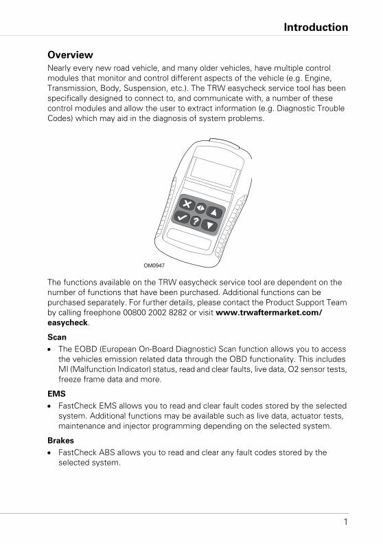
Nearly every new road vehicle, and many older vehicles, have multiple control modules that monitor and control different aspects of the vehicle (e.g. Engine, Transmission, Body, Suspension, etc.). The TRW easycheck service tool has been specifically designed to connect to, and communicate with, a number of these control modules and allow the user to extract information (e.g. Diagnostic Trouble Codes) which may aid in the diagnosis of system problems.
The functions available on the TRW easycheck service tool are dependent on the number of functions that have been purchased. Additional functions can be purchased separately. For further details, please contact the Product Support Team by calling freephone 00800 2002 8282 or visit www.trwaftermarket.com/
easycheck.
Scan
• The EOBD (European On-Board Diagnostic) Scan function allows you to access the vehicles emission related data through the OBD functionality. This includes MI (Malfunction Indicator) status, read and clear faults, live data, O2 sensor tests, freeze frame data and more.
EMS
• FastCheck EMS allows you to read and clear fault codes stored by the selected system. Additional functions may be available such as live data, actuator tests, maintenance and injector programming depending on the selected system.
Brakes
• FastCheck ABS allows you to read and clear any fault codes stored by the selected system.
OM0947
Introduction
2
• FastCheck EPB (Electronic Parking Brake) allows you to read and clear any fault codes stored by the selected system, and in addition can be used during brake operation checks or brake pad replacement.
SRS
• FastCheck Airbag allows you to read and clear any fault codes stored by the selected system.
Climate
• FastCheck Climate allows you to read and clear any fault codes stored by the selected system.
SAS
• FastCheck SAS (Steering Angle Sensor) allows you to read and clear any fault codes stored by the selected system, and in addition can be used to calibrate the steering angle sensor.
Service
• FastCheck Service allows you to reset, dependant upon vehicle, the oil service interval indicator, service and inspection warning lights.
TPMS
• The ‘TPMS’ (Tyre Pressure Monitoring System) function can be used to re-program TPMS tyre valves to the control module.
If you are using the service tool for the first time, it is recommended that you read these instructions and safety guidelines fully, prior to commencing any testing on a vehicle.
Getting started
Connect the Multiplexer cable (YTD965) or the EOBD cable (YTD950) to the service tool and the vehicle's diagnostic connector. Once connected, the current software version number is displayed.
Registration and unlocking of units
A new or updated service tool requires a security key to unlock the specific functions. To register the service tool, log on to
www.trwaftermarket.com/easycheck
and select the link to the administration centre.
Auto-activation is possible using the website if an update cable is available. Alternatively, after obtaining your security key from the web site, use the following procedure to unlock your service tool:
1. Select 'User Menu' from the main menu.
2. Select 'Security' from the user menu.
Introduction
3
3. Select 'Enter Security Key' from the security menu.
4. Using the and keys, scroll through the alpha/numerical character list.
5. Confirm each character by pressing the key.
If you make a mistake use the key and enter the correct character. To re-enter the code from the beginning, press the key.
6. When prompted to verify the security key, press to confirm.
7. Power down the service tool by disconnecting the power source.
8. Reconnect the power supply to restart the service tool. The screen should now show a list of the functions included.
Further support can be obtained by calling freephone 00800 2002 8282.
Introduction
4
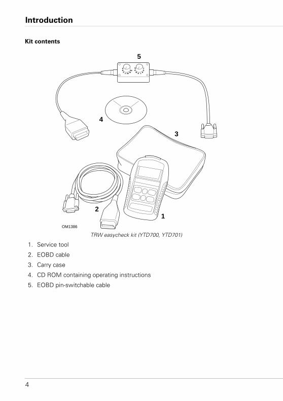
Kit contents
TRW easycheck kit (YTD700, YTD701)
1. Service tool
2. EOBD cable
3. Carry case
4. CD ROM containing operating instructions
5. EOBD pin-switchable cable
OM1386
12
3
4
5
1 12
432
1011
A L
DC
B
IJ
K
Introduction
5
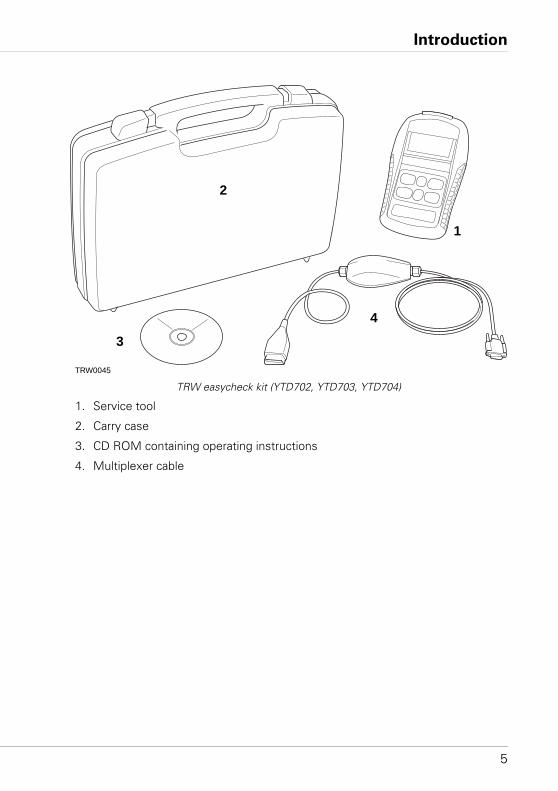
TRW easycheck kit (YTD702, YTD703, YTD704)
1. Service tool
2. Carry case
3. CD ROM containing operating instructions
4. Multiplexer cable
TRW0045
1
2
4
3
Introduction
6
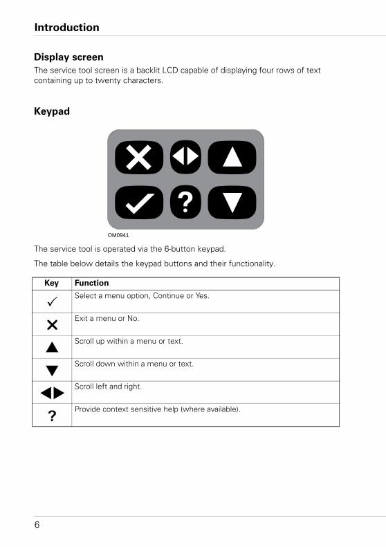
Display screen
The service tool screen is a backlit LCD capable of displaying four rows of text containing up to twenty characters.
Keypad
The service tool is operated via the 6-button keypad.
The table below details the keypad buttons and their functionality.
Key Function
Select a menu option, Continue or Yes.
Exit a menu or No.
Scroll up within a menu or text.
Scroll down within a menu or text.
Scroll left and right.
Provide context sensitive help (where available).
OM0941
Introduction
7
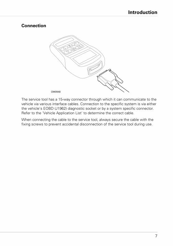
Connection
The service tool has a 15-way connector through which it can communicate to the vehicle via various interface cables. Connection to the specific system is via either the vehicle's EOBD (J1962) diagnostic socket or by a system specific connector. Refer to the 'Vehicle Application List' to determine the correct cable.
When connecting the cable to the service tool, always secure the cable with the fixing screws to prevent accidental disconnection of the service tool during use.
OM0948
Introduction
8
Safety precautions
The following guidelines are intended to ensure the safety of the operator whilst preventing damage to the electrical and electronic components fitted to the vehicle.
Equipment - prior to commencing any test procedure on the vehicle, ensure that the service tool, its harnesses and connectors are in good condition.
Polarity - always observe the correct polarity when connecting the service tool to the vehicle battery
Before carrying out testing on a vehicle, the following procedure should always be observed:• Check the handbrake/parking brake is ON.• Check that neutral or park is selected.• Keep test equipment and harnesses away from HT leads.• Be aware of moving engine parts.• Do not run engine in a confined space without adequate ventilation.
Communication problems
If communications cannot be established with the vehicle, follow the procedure below:
1. Check the correct system was selected from the menu.
2. Check the correct cable was used against the application list.
3. Disconnect both ends of the cable and ensure that no pins are bent or snapped.
4. Reset the control module on the vehicle by turning the ignition OFF and ON, reconnect the service tool and try again.
If communications still cannot be established, contact the Product Support Team desk for further assistance.
Scan function - EOBD
9
Scan function - EOBDWhat is EOBD?
The American Environmental Protection Agency and the European government have set targets for reducing the levels of pollution produced by passenger and commercial vehicles. In order to ensure that these targets can be met, manufacturers are required to build new vehicles which meet increasingly stiff emissions standards. The manufacturers must further maintain these emission standards for the useful life of the vehicle. In order to meet and maintain these standards the vehicles are fitted with On-Board Diagnostic systems which monitor the integrity and effectiveness of all emission related components.
As vehicles are becoming more and more complex, many of the systems fitted to them are being controlled by electronic control modules. Most vehicles now have multiple control modules (e.g. Engine, Transmission, Body, Suspension, etc.) located at different locations on the vehicle. The On-Board Diagnostic systems are integrated into the vehicle control modules.
With so many different vehicle and component manufacturers, a common interface was required to communicate with these control modules. In 1988, the SAE (Society of Automotive Engineers) created a standard that defined a standard diagnostic socket (J1962) and a set of diagnostic test signals.
With the diagnostic socket and diagnostic signals agreed, another standard was produced that defined a universal inspection and diagnosis method to ensure that a vehicle is performing to Original Equipment Manufacturer (OEM) specifications. This standard is known as EOBD (European On-Board Diagnostics).
The fundamental requirement for an EOBD system is that in the event of an emissions related component fault, a DTC (Diagnostic Trouble Code) will be stored in the memory of the control module responsible for that component, and a Malfunction Indicator Lamp (MIL) will illuminate on the vehicle's instrument pack to alert the driver. The DTC can then be retrieved using diagnostic equipment to determine the type and status of the fault.
Scan function - EOBD
10
Identifying compliant vehicles
All petrol engine vehicles manufactured since 2000 should be EOBD compliant. Some manufacturers began incorporating On-Board Diagnostic systems as early as 1994, however not all are 100% compliant. All diesel engine vehicles are expected to have support from 2004. This means that diagnostic information, related to vehicle emissions, may be extracted from the vehicle via the J1962 diagnostic socket using the service tool.
The service tool can communicate with any EOBD compliant vehicle using one of the five diagnostic communication protocols defined in the standard.
These are• ISO 9141.• Keyword 2000 (originally a European protocol).• J1850 PWM (pulse width modulated) protocol used by Ford.• J1850 VPW (variable pulse width modulated) used by General Motors in USA
designed vehicles.• CAN (controller area network) currently being legislated for and likely to be a
principle diagnostic communication system in the future. A European protocol.
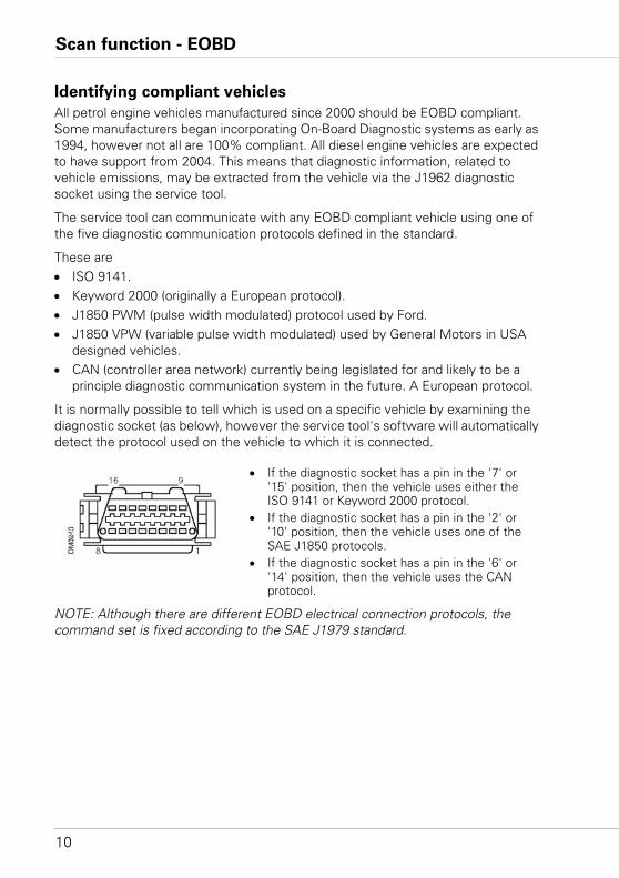
It is normally possible to tell which is used on a specific vehicle by examining the diagnostic socket (as below), however the service tool's software will automatically detect the protocol used on the vehicle to which it is connected.
NOTE: Although there are different EOBD electrical connection protocols, the command set is fixed according to the SAE J1979 standard.
• If the diagnostic socket has a pin in the '7' or '15' position, then the vehicle uses either the ISO 9141 or Keyword 2000 protocol.
• If the diagnostic socket has a pin in the '2' or '10' position, then the vehicle uses one of the SAE J1850 protocols.
• If the diagnostic socket has a pin in the '6' or '14' position, then the vehicle uses the CAN protocol.
Scan function - EOBD
11
Diagnostic Trouble Codes
Diagnostic Trouble Codes (DTCs) are divided into mandatory and voluntary codes. Mandatory codes are allocated by the ISO (International Standards Organisation) / SAE (Society of Automotive Engineers). Voluntary codes are allocated by various vehicle manufacturers and are manufacturer specific and in some instances, vehicle specific.
ISO/SAE controlled diagnostic trouble codes are those codes where industry uniformity has been achieved. These codes were felt to be common enough across most manufacturer's applications that a common number and fault message could be assigned. All unspecified numbers in each grouping have been reserved for future growth. Although service procedures may differ widely amongst manufacturers, the fault being indicated is common enough to be assigned a particular fault code. Codes in this area are not to be used by manufacturers until they have been approved by ISO/SAE.
Areas within each of the fault code blocks have been allocated for manufacturer controlled DTCs. These are fault codes that will not generally be used by the majority of the manufacturers due to basic system differences, implementation differences, or diagnostic strategy differences.
Scan function - EOBD
12
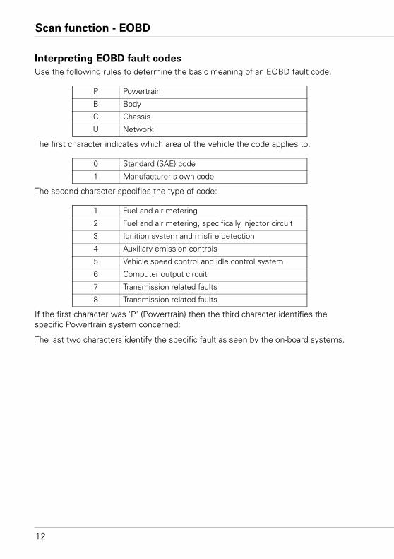
Interpreting EOBD fault codes
Use the following rules to determine the basic meaning of an EOBD fault code.
The first character indicates which area of the vehicle the code applies to.
The second character specifies the type of code:
If the first character was 'P' (Powertrain) then the third character identifies the specific Powertrain system concerned:
The last two characters identify the specific fault as seen by the on-board systems.
P Powertrain
B Body
C Chassis
U Network
0 Standard (SAE) code
1 Manufacturer's own code
1 Fuel and air metering
2 Fuel and air metering, specifically injector circuit
3 Ignition system and misfire detection
4 Auxiliary emission controls
5 Vehicle speed control and idle control system
6 Computer output circuit
7 Transmission related faults
8 Transmission related faults
Scan function - EOBD
13
Using scan function
Connection and basic operation
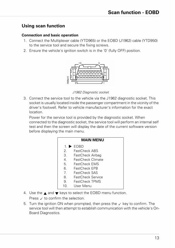
1. Connect the Multiplexer cable (YTD965) or the EOBD (J1962) cable (YTD950) to the service tool and secure the fixing screws.
2. Ensure the vehicle's ignition switch is in the '0' (fully OFF) position.
J1962 Diagnostic socket
3. Connect the service tool to the vehicle via the J1962 diagnostic socket. This socket is usually located inside the passenger compartment in the vicinity of the driver's footwell. Refer to vehicle manufacturer's information for the exact location. Power for the service tool is provided by the diagnostic socket. When connected to the diagnostic socket, the service tool will perform an internal self test and then the screen will display the date of the current software version before displaying the main menu.
4. Use the and keys to select the EOBD menu function.Press to confirm the selection.
5. Turn the ignition ON when prompted, then press the key to confirm. The service tool will then attempt to establish communication with the vehicle's On-Board Diagnostics.
MAIN MENU
1. EOBD2. FastCheck ABS3. FastCheck Airbag4. FastCheck Climate5. FastCheck EMS6. FastCheck EPB7. FastCheck SAS8. FastCheck Service9. FastCheck TPMS
10. User Menu
Scan function - EOBD
14
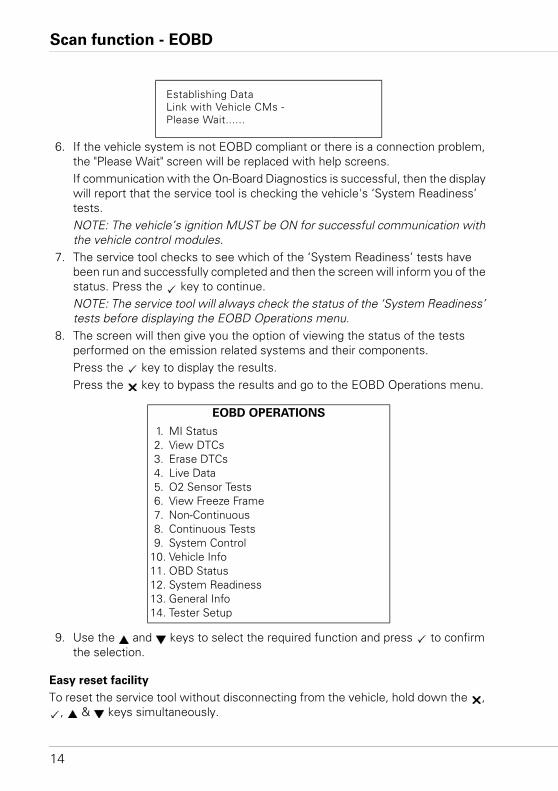
6. If the vehicle system is not EOBD compliant or there is a connection problem, the "Please Wait" screen will be replaced with help screens.If communication with the On-Board Diagnostics is successful, then the display will report that the service tool is checking the vehicle's ‘System Readiness’ tests.NOTE: The vehicle’s ignition MUST be ON for successful communication with the vehicle control modules.
7. The service tool checks to see which of the ‘System Readiness’ tests have been run and successfully completed and then the screen will inform you of the status. Press the key to continue.NOTE: The service tool will always check the status of the ‘System Readiness’ tests before displaying the EOBD Operations menu.
8. The screen will then give you the option of viewing the status of the tests performed on the emission related systems and their components.Press the key to display the results.Press the key to bypass the results and go to the EOBD Operations menu.
9. Use the and keys to select the required function and press to confirm the selection.
Easy reset facility
To reset the service tool without disconnecting from the vehicle, hold down the , , & keys simultaneously.
Establishing DataLink with Vehicle CMs - Please Wait......
EOBD OPERATIONS
1. MI Status2. View DTCs3. Erase DTCs4. Live Data5. O2 Sensor Tests6. View Freeze Frame7. Non-Continuous8. Continuous Tests9. System Control
10. Vehicle Info11. OBD Status12. System Readiness13. General Info14. Tester Setup
Scan function - EOBD
15
Menu options
Not all vehicle control modules will support all of the options available from the menu. If an option is not supported the service tool will display either “Not Supported” or “Not Available”. This is a limitation of the software on the vehicle control modules and NOT a fault with the service tool.
MI Status/MIL Status
'MI Status' or 'MIL Status' displays the status of the malfunction indicator lamp for each emissions related control module. If the status of the MIL is set to ON, one or more DTCs will be stored in the vehicle's control modules and the instrument panel MIL will be illuminated.
View DTCs
This option allows any 'Stored' or 'Continuous' emission related DTCs (Diagnostic Trouble Codes) to be viewed. If any DTC is present, it will be displayed along with the identity of the Control Module (CM) that registered the fault.
If more than one DTC is displayed, the required DTC can be selected by using the and keys. Press to select the DTC and display the description of the code.
Dependant upon the DTC and the vehicle manufacturer, it may be necessary to select the manufacturer and possibly also the model of the vehicle to enable the correct description to be displayed. This setting will be retained while the service tool is being used for EOBD operations but can be redefined or cleared under the 'Manufacturer' menu option.
Erase DTCs
This option will clear all 'Stored' and 'Continuous' emission related DTCs, clear 'Freeze Frame' DTCs and associated data, clear 'O2 Sensor Test' data, clear 'Non-Continuous' test results and reset the status of the 'System Readiness' tests on the control modules on the vehicle. The service tool will then perform a 'Read DTCs' operation to verify that the DTCs have been erased.
Live Data
This option allows the user to view the current status of the emission system components on the vehicle and can provide a quick way of telling if a component is working correctly.
The list of components monitored under 'Live Data' can vary between manufacturers and even between model.
Scan function - EOBD
16
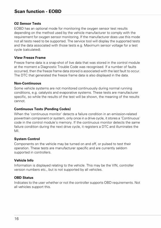
O2 Sensor Tests
EOBD has an optional mode for monitoring the oxygen sensor test results depending on the method used by the vehicle manufacturer to comply with the requirement for oxygen sensor monitoring. If the manufacturer does use this mode not all tests need to be supported. The service tool will display the supported tests and the data associated with those tests e.g. Maximum sensor voltage for a test cycle (calculated).
View Freeze Frame
Freeze frame data is a snap-shot of live data that was stored in the control module at the moment a Diagnostic Trouble Code was recognised. If a number of faults occurred, then the freeze frame data stored is associated with the last fault to occur. The DTC that generated the freeze frame data is also displayed in the data.
Non-Continuous
Some vehicle systems are not monitored continuously during normal running conditions, e.g. catalysts and evaporative systems. These tests are manufacturer specific, so while the results of the test will be shown, the meaning of the results cannot.
Continuous Tests (Pending Codes)
When the 'continuous monitor' detects a failure condition in an emission-related powertrain component or system, only once in a drive cycle, it stores a 'Continuous' code in the control module's memory. If the continuous monitor detects the same failure condition during the next drive cycle, it registers a DTC and illuminates the MI.
System Control
Components on the vehicle may be turned on and off, or pulsed to test their operation. These tests are manufacturer specific and are currently seldom supported in controllers.
Vehicle Info
Information is displayed relating to the vehicle. This may be the VIN, controller version numbers etc., but is not supported by all vehicles.
OBD Status
Indicates to the user whether or not the controller supports OBD requirements. Not all vehicles support this.
Scan function - EOBD
17
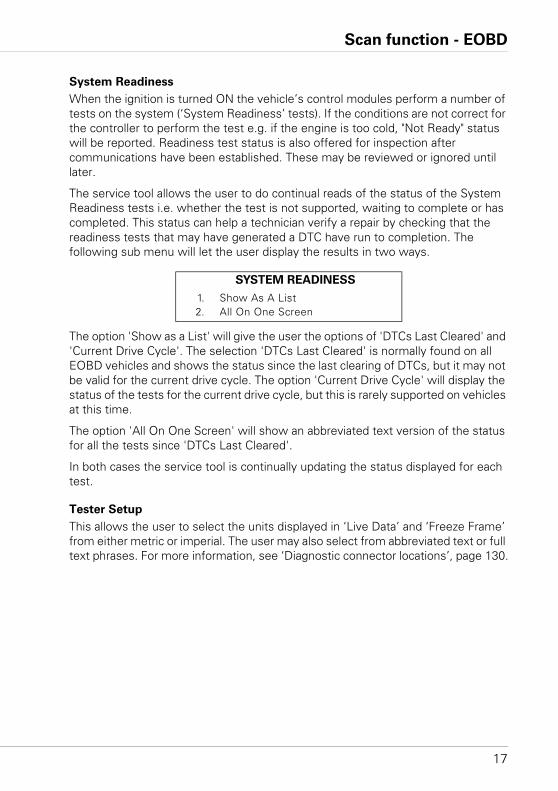
System Readiness
When the ignition is turned ON the vehicle’s control modules perform a number of tests on the system (‘System Readiness’ tests). If the conditions are not correct for the controller to perform the test e.g. if the engine is too cold, "Not Ready" status will be reported. Readiness test status is also offered for inspection after communications have been established. These may be reviewed or ignored until later.
The service tool allows the user to do continual reads of the status of the System Readiness tests i.e. whether the test is not supported, waiting to complete or has completed. This status can help a technician verify a repair by checking that the readiness tests that may have generated a DTC have run to completion. The following sub menu will let the user display the results in two ways.
The option 'Show as a List' will give the user the options of 'DTCs Last Cleared' and 'Current Drive Cycle'. The selection 'DTCs Last Cleared' is normally found on all EOBD vehicles and shows the status since the last clearing of DTCs, but it may not be valid for the current drive cycle. The option 'Current Drive Cycle' will display the status of the tests for the current drive cycle, but this is rarely supported on vehicles at this time.
The option 'All On One Screen' will show an abbreviated text version of the status for all the tests since 'DTCs Last Cleared'.
In both cases the service tool is continually updating the status displayed for each test.
Tester Setup
This allows the user to select the units displayed in ‘Live Data’ and ‘Freeze Frame’ from either metric or imperial. The user may also select from abbreviated text or full text phrases. For more information, see ‘Diagnostic connector locations’, page 130.
SYSTEM READINESS
1. Show As A List2. All On One Screen
FastCheck
18
FastCheckIntroduction
The 'FastCheck' functions allow the service tool to communicate with other system control modules on the vehicle.
Connection to the specific system is via either the vehicle's EOBD (J1962) diagnostic socket or by a system specific connector. Refer to the 'Vehicle Application List' to determine the correct cable.
Brake
• ‘FastCheck ABS’ allows you to read and clear any fault codes stored by the selected system.
• ‘FastCheck EPB’ (Electronic Parking Brake) allows you to read and clear any fault codes stored by the selected system, and in addition can be used during brake operation checks or brake pad replacement.
SRS
• ‘FastCheck Airbag’ allows you to read and clear any fault codes stored by the selected system.
Climate
• ‘FastCheck Climate’ allows you to read and clear any fault codes stored by the selected system.
EMS
• ‘FastCheck EMS’ allows you to read and clear fault codes stored by the selected system. Additional functions may be available such as live data, actuator tests, maintenance and injector reprogramming depending on the selected system.
SAS
• ‘FastCheck SAS’ (Steering Angle Sensor) allows you to read and clear any fault codes stored by the selected system, and in addition can be used to calibrate the steering angle sensor.
Service
• ‘FastCheck Service’ allows you to reset, dependant upon vehicle, the oil service interval indicator, service and inspection warning lights.
TPMS
• The ‘TPMS’ (Tyre Pressure Monitoring System) function can be used to re-program TPMS tyre valves to the control module.
FastCheck
19
Safety instructions
WARNING: General safety
• All operations must be carried out in a well ventilated area away from open
flame and heat sources.
• Ensure the vehicle is stationary and the handbrake (parking brake) is
applied before carrying out any maintenance/diagnostic work.
WARNING: Air conditioning safety
• Servicing must only be carried out if you are familiar with both the vehicle
system and the test equipment.
• Air conditioning refrigerant is a hazardous liquid and when handled
incorrectly can cause serious injury. Suitable protective clothing, consisting
of face protection, heat proof gloves, rubber boots and rubber apron or
waterproof overalls, must be worn when carrying out operations on the air
conditioning system.
• Danger of asphyxiation, refrigerant gas is heavier than air and will collect
in vehicle inspection pits or confined spaces, always recover all refrigerant
from a damaged system before commencing work.
WARNING: Airbag safety
• All work on vehicle restraint systems should be carried out by trained
personnel. NEVER install accessories in the vicinity of driver, passenger or
side airbags.
• Observe component manufacturers instructions for safety, handling and
installation of components.
• Airbags are classed as explosive devices and as such are subject to national
laws which must be followed. This includes storage and transportation.
• ALWAYS store removed airbags in a secure area away from other
hazardous materials.
• DO NOT connect or disconnect any wiring with the ignition ON. ALWAYS
turn the ignition switch to the 'OFF' position and allow at least 1 minute for
the system to discharge.
• NEVER expose system components to temperatures above 176°F (80°C).
• ONLY use approved diagnostic testers to diagnose faults, NEVER use
multi-meters or test lamps etc.
• ALWAYS disconnect all airbags and seat belt pre-tensioners before using a
multi-meter to check the wiring.
FastCheck
20
WARNING: Electronic Parking Brake (EPB) safety
• Ensure that you are fully familiar with the braking system and its operation
before commencing any work.
• The EPB control system may be required to be deactivated before carrying
out any maintenance/diagnostic work on the brake system. This can be
done from the service tool menu.
• Only carry out maintenance work when the vehicle is stationary and on
level ground.
• Ensure that the EPB control system is reactivated after the maintenance
work has been completed.
NOTE: TRW accept no responsibility for any accident or injury arising from the maintenance of the Electronic Parking Brake system.
FastCheck
21
FastCheck ABS
Connection
Using the Vehicle Application List on the CD-ROM, identify the required interface cable for the vehicle system to be tested. Connect the cable to the service tool and secure the fixing screws.
NOTE: If the vehicle being tested is a BMW with a 20 pin connector and an EOBD (J1962) connector, you must only use the 20 pin connector.
NOTE: The Multiplexer cable (YTD965) or the CAN converter (YTD960) harness must be used for any diagnostics on the following vehicles:
BMW 1 series (E81/E87)
BMW 3 series (E90/E91/E92/E93)
BMW 5 series (E60/E61)
BMW 6 series (E63/E64)
BMW 7 series (E65)
GM Opel/Vauxhall - Corsa D
GM Opel/Vauxhall - Signum
GM Opel/Vauxhall - Vectra C
GM Opel/Vauxhall - Zafira B
Important information
Mercedes vehicles with Sensotronic Brake Control
• Ensure that you are fully familiar with the braking system and its operation before commencing any work.
• The Sensotronic Brake Control system must be deactivated before carrying out any maintenance/diagnostic work on the brake system. This can be done from the service tool menu.
• Only commence work after the system has been deactivated. Upon deactivation, a warning message should appear in the instrument panel accompanied by an audible warning signal until the system is reactivated. If the warning signals do not occur, assume that the system is not fully deactivated and DO NOT commence work.
• Ensure that the Sensotronic Brake Control system is reactivated after the maintenance work has been completed.
NOTE: The manufacturer of the service tool accept no responsibility for any accident or injury arising from the maintenance of the Sensotronic Brake Control system.
FastCheck
22
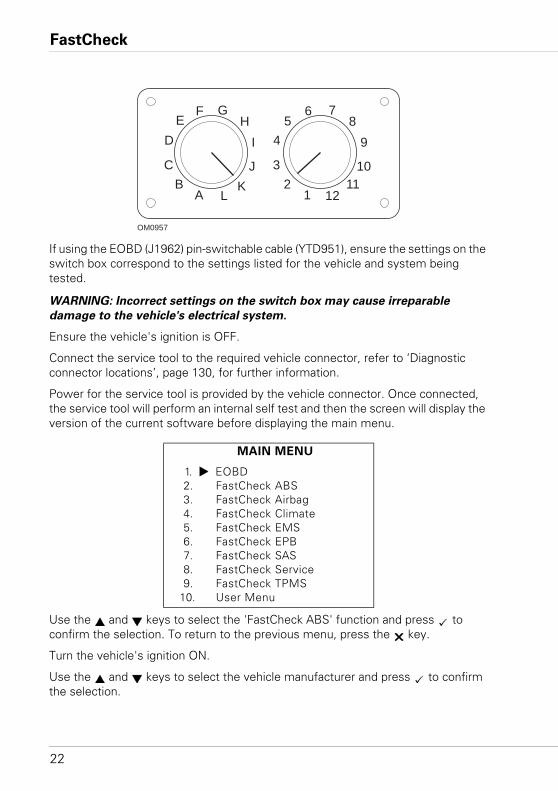
If using the EOBD (J1962) pin-switchable cable (YTD951), ensure the settings on the switch box correspond to the settings listed for the vehicle and system being tested.
WARNING: Incorrect settings on the switch box may cause irreparable
damage to the vehicle's electrical system.
Ensure the vehicle's ignition is OFF.
Connect the service tool to the required vehicle connector, refer to ‘Diagnostic connector locations’, page 130, for further information.
Power for the service tool is provided by the vehicle connector. Once connected, the service tool will perform an internal self test and then the screen will display the version of the current software before displaying the main menu.
Use the and keys to select the 'FastCheck ABS' function and press to confirm the selection. To return to the previous menu, press the key.
Turn the vehicle's ignition ON.
Use the and keys to select the vehicle manufacturer and press to confirm the selection.
MAIN MENU
1. EOBD2. FastCheck ABS3. FastCheck Airbag4. FastCheck Climate5. FastCheck EMS6. FastCheck EPB7. FastCheck SAS8. FastCheck Service9. FastCheck TPMS
10. User Menu
AB
C
DE
F GH
I
JK
L 12
3
45
6 78
9
1011
12
OM0957
FastCheck
23
Dependant upon the vehicle and function being run, you may be asked to choose the particular system fitted to the vehicle. Select the correct system using the and keys and press to confirm.
Select the required menu option using the and keys and press to confirm.
The service tool will attempt to establish communication with the vehicle system. If communication is unsuccessful, refer to ‘Communication problems’, page 8.
Read DTCs
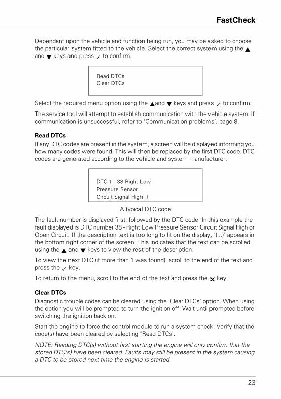
If any DTC codes are present in the system, a screen will be displayed informing you how many codes were found. This will then be replaced by the first DTC code. DTC codes are generated according to the vehicle and system manufacturer.
A typical DTC code
The fault number is displayed first, followed by the DTC code. In this example the fault displayed is DTC number 38 - Right Low Pressure Sensor Circuit Signal High or Open Circuit. If the description text is too long to fit on the display, '(...)' appears in the bottom right corner of the screen. This indicates that the text can be scrolled using the and keys to view the rest of the description.
To view the next DTC (if more than 1 was found), scroll to the end of the text and press the key.
To return to the menu, scroll to the end of the text and press the key.
Clear DTCs
Diagnostic trouble codes can be cleared using the 'Clear DTCs' option. When using the option you will be prompted to turn the ignition off. Wait until prompted before switching the ignition back on.
Start the engine to force the control module to run a system check. Verify that the code(s) have been cleared by selecting 'Read DTCs'.
NOTE: Reading DTC(s) without first starting the engine will only confirm that the stored DTC(s) have been cleared. Faults may still be present in the system causing a DTC to be stored next time the engine is started.
Read DTCsClear DTCs
DTC 1 - 38 Right LowPressure SensorCircuit Signal High{ }

FastCheck
24
BMW/MINI vehicles
NOTE: To switch the ignition ON for vehicles fitted with a start/stop button, insert the remote key-fob fully into the ignition slot then press the start/stop button once (without any foot pedals depressed).
FastCheck
25
FastCheck Airbag
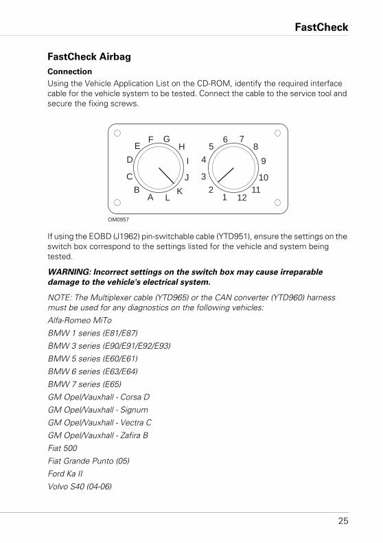
Connection
Using the Vehicle Application List on the CD-ROM, identify the required interface cable for the vehicle system to be tested. Connect the cable to the service tool and secure the fixing screws.
If using the EOBD (J1962) pin-switchable cable (YTD951), ensure the settings on the switch box correspond to the settings listed for the vehicle and system being tested.
WARNING: Incorrect settings on the switch box may cause irreparable
damage to the vehicle's electrical system.
NOTE: The Multiplexer cable (YTD965) or the CAN converter (YTD960) harness must be used for any diagnostics on the following vehicles:
Alfa-Romeo MiTo
BMW 1 series (E81/E87)
BMW 3 series (E90/E91/E92/E93)
BMW 5 series (E60/E61)
BMW 6 series (E63/E64)
BMW 7 series (E65)
GM Opel/Vauxhall - Corsa D
GM Opel/Vauxhall - Signum
GM Opel/Vauxhall - Vectra C
GM Opel/Vauxhall - Zafira B
Fiat 500
Fiat Grande Punto (05)
Ford Ka II
Volvo S40 (04-06)
AB
C
DE
F GH
I
JK
L 12
3
45
6 78
9
1011
12
OM0957
FastCheck
26
Volvo V50 (03-08)
Volvo S60 (01-05)
Volvo V70 (00-07)
Volvo XC70 (00-06)
Volvo S80 (99-06)
Volvo XC90 (02-06)
Ensure the vehicle's ignition is OFF.
Connect the service tool to the required vehicle connector, refer to ‘Diagnostic connector locations’, page 130, for further information.
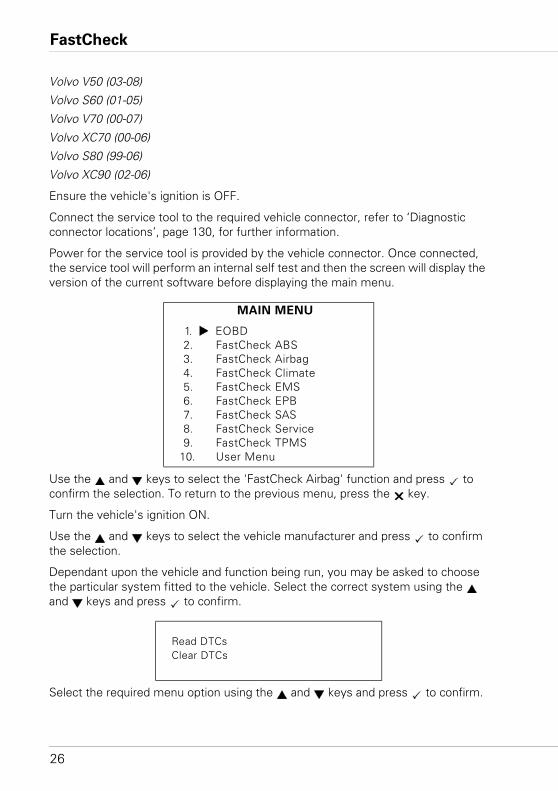
Power for the service tool is provided by the vehicle connector. Once connected, the service tool will perform an internal self test and then the screen will display the version of the current software before displaying the main menu.
Use the and keys to select the 'FastCheck Airbag' function and press to confirm the selection. To return to the previous menu, press the key.
Turn the vehicle's ignition ON.
Use the and keys to select the vehicle manufacturer and press to confirm the selection.
Dependant upon the vehicle and function being run, you may be asked to choose the particular system fitted to the vehicle. Select the correct system using the and keys and press to confirm.
Select the required menu option using the and keys and press to confirm.
MAIN MENU
1. EOBD2. FastCheck ABS3. FastCheck Airbag4. FastCheck Climate5. FastCheck EMS6. FastCheck EPB7. FastCheck SAS8. FastCheck Service9. FastCheck TPMS
10. User Menu
Read DTCsClear DTCs
FastCheck
27
The service tool will attempt to establish communication with the vehicle system. If communication is unsuccessful, refer to ‘Communication problems’, page 8.
Read DTCs
If any DTC codes are present in the system, a screen will be displayed informing you how many codes were found. This will then be replaced by the first DTC code. DTC codes are generated according to the vehicle and system manufacturer.
The fault number is displayed first, followed by the DTC code. If the description text is too long to fit on the display, '(...)' appears in the bottom right corner of the screen. This indicates that the text can be scrolled using the and keys to view the rest of the description.
To view the next DTC (if more than 1 was found), scroll to the end of the text and press the key.
To return to the menu, scroll to the end of the text and press the key.
Clear DTCs
Diagnostic trouble codes can be cleared using the 'Clear DTCs' option. When using the option you will be prompted to turn the ignition OFF. Wait until prompted before switching the ignition back ON.
Verify that the code(s) have been cleared by selecting 'Read DTCs'.
BMW vehicles
NOTE: To switch the ignition ON for vehicles fitted with a start/stop button, insert the remote key-fob fully into the ignition slot then press the start/stop button once (without any foot pedals depressed).
Some BMW vehicles are equipped with multiple airbag systems, one for each airbag fitted to the vehicle.
Applicable Vehicles:• BMW 3 series (E90/E91/E92/E93)• BMW 5 series (E60/E61)• BMW 6 series (E63/E64)• BMW 7 series (E65)• BMW Z4 (E85)
If on selecting the Read DTCs or Clear DTCs and a multiple airbag system is detected, then a menu containing a list of airbag systems fitted to the vehicle will be displayed.
FastCheck
28
Use the and keys to select the required system from the menu shown. Press the key to select the system required the Read DTCs or Clear DTCs will be performed. Press the key while the system menu is displayed to return back to the Read DTCs and Clear DTCs menu.
All airbag ECU’s
If the All airbag ECU’s was selected then the Read DTCs or Clear DTCs function will be performed on ALL detected airbag systems on the vehicle.
MINI vehicles
NOTE: To switch the ignition ON for vehicles fitted with a start/stop button, insert the remote key-fob fully into the ignition slot then press the start/stop button once (without any foot pedals depressed).
Ford Galaxy (2006 -), Mondeo (2007-), S-Max (2006-), Transit (2006-)
Crash Reset
This option is necessary on vehicles where airbags have been deployed following a crash. The routine clears the crash flag in the Body Control Module to enable normal operation after repair of the vehicle and installation of a new airbag.
Land Rover Freelander 2 (2007-)
Restraints Build Mode Entry/Exit
This function can be used to place the Airbag/Restraint system in to build mode, to enable safe maintenance and repairs to be performed without risk of airbag or pretensioner detonation. When work has been completed on the system, the Airbag/Restraints system can be taken out of build mode to enable normal operation.
Crash Reset
This option is necessary on vehicles where airbags have been deployed following a crash. The routine clears the crash flag in the Body Control Module to enable normal operation after repair of the vehicle and installation of a new airbag.
Renault vehicles
Select the airbag system then select either 12-pin or 16-pin according to which connector is fitted to the vehicle under test.Then follow the on screen instructions.
The following functions are available for the airbag system:
1. Read DTCs: Displays all diagnostic trouble codes associated with the airbag system
2. Clear DTCs: Clears all faults codes from the airbag system.
3. Renault Arm/Disarm for Driver/Passenger Airbag:

FastCheck
29
The Disarm CM (LOCK) menu option allows the driver airbag to be disabled preventing accidental deployment while working on the car.
The Arm CM (UNLOCK) menu option causes the driver airbag to become active.
The Disarm Passenger (LOCK) menu option allows the passenger airbag to be disabled preventing accidental deployment while working on the car.
The Arm Passenger (UNLOCK) menu option causes the passenger airbag to become active.
NOTE: Not all vehicles will have a passenger airbag and some vehicles with a passenger airbag cannot be armed/disarmed using a diagnostic tool (they require a key to be inserted into the arm/disarm lock located next to the passenger airbag).
Vehicle notification methods for a locked airbag
Method 1 - Fault Code present:
If the user reads airbag diagnostic codes after an airbag has been locked some models will produce an 'Airbag locked' fault code. After unlocking, this fault code will not appear, this can be confirmed by reading the diagnostic codes again.
Method 2 - Airbag MIL stays ON:
After an airbag has been locked the Airbag Malfunction Indicator on the dash panel display will remain on, when the airbag is unlocked the MIL will switch off.
Method 3 - Airbag MIL flashes for several seconds when turning the ignition
on:
After an airbag has been locked the Airbag Malfunction Indicator on the dash panel display will flash for several seconds when the ignition is turned on, when the airbag is unlocked the MIL will switch off.
FastCheck
30
FastCheck Climate
Connection
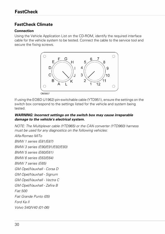
Using the Vehicle Application List on the CD-ROM, identify the required interface cable for the vehicle system to be tested. Connect the cable to the service tool and secure the fixing screws.
If using the EOBD (J1962) pin-switchable cable (YTD951), ensure the settings on the switch box correspond to the settings listed for the vehicle and system being tested.
WARNING: Incorrect settings on the switch box may cause irreparable
damage to the vehicle's electrical system.
NOTE: The Multiplexer cable (YTD965) or the CAN converter (YTD960) harness must be used for any diagnostics on the following vehicles:
Alfa-Romeo MiTo
BMW 1 series (E81/E87)
BMW 3 series (E90/E91/E92/E93)
BMW 5 series (E60/E61)
BMW 6 series (E63/E64)
BMW 7 series (E65)
GM Opel/Vauxhall - Corsa D
GM Opel/Vauxhall - Signum
GM Opel/Vauxhall - Vectra C
GM Opel/Vauxhall - Zafira B
Fiat 500
Fiat Grande Punto (05)
Ford Ka II
Volvo S40/V40 (01-06)
FastCheck
31
Volvo V50 (03-08)
Volvo S60 (01-05)
Volvo V70 (99-07)
Volvo XC70 (00-06)
Volvo S80 (99-06)
Volvo XC90 (02-06)
Volvo S70 (99-00)
Volvo C70 Convertible/Coupe (99-05)
Ensure the vehicle's ignition is OFF.
Connect the service tool to the required vehicle connector, refer to ‘Diagnostic connector locations’, page 130, for further information.
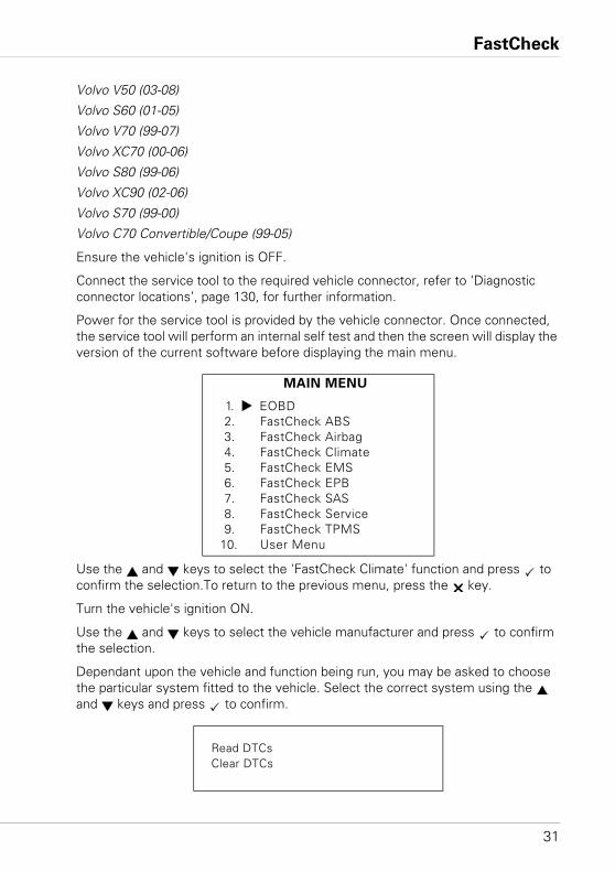
Power for the service tool is provided by the vehicle connector. Once connected, the service tool will perform an internal self test and then the screen will display the version of the current software before displaying the main menu.
Use the and keys to select the 'FastCheck Climate' function and press to confirm the selection.To return to the previous menu, press the key.
Turn the vehicle's ignition ON.
Use the and keys to select the vehicle manufacturer and press to confirm the selection.
Dependant upon the vehicle and function being run, you may be asked to choose the particular system fitted to the vehicle. Select the correct system using the and keys and press to confirm.
MAIN MENU
1. EOBD2. FastCheck ABS3. FastCheck Airbag4. FastCheck Climate5. FastCheck EMS6. FastCheck EPB7. FastCheck SAS8. FastCheck Service9. FastCheck TPMS
10. User Menu
Read DTCsClear DTCs
FastCheck
32
Select the required menu option using the and keys and press to confirm.
The service tool will attempt to establish communication with the vehicle system. If communication is unsuccessful, refer to ‘Communication problems’, page 8.
Read DTCs
If any DTC codes are present in the system, a screen will be displayed informing you how many codes were found. This will then be replaced by the first DTC code. DTC codes are generated according to the vehicle and system manufacturer.
The fault number is displayed first, followed by the DTC code. If the description text is too long to fit on the display, '(...)’ appears in the bottom right corner of the screen. This indicates that the text can be scrolled using the and keys to view the rest of the description.
To view the next DTC (if more than 1 was found), scroll to the end of the text and press the key.
To return to the menu, scroll to the end of the text and press the key.
Clear DTCs
Diagnostic trouble codes can be cleared using the 'Clear DTCs' option. When using the option you will be prompted to turn the ignition OFF. Wait until prompted before switching the ignition back ON.
Start the engine to force the control module to run a system check. Verify that the code(s) have been cleared by selecting 'Read DTCs'.
NOTE: Reading DTC(s) without first starting the engine will only confirm that the stored DTC(s) have been cleared. Faults may still be present in the system causing a DTC to be stored next time the engine is started.
BMW/MINI vehicles
NOTE: To switch the ignition ON for vehicles fitted with a start/stop button, insert the remote key-fob fully into the ignition slot then press the start/stop button once (without any foot pedals depressed).
FastCheck
33
FastCheck EMS
Connection
Using the Vehicle Application List on the CD-ROM, identify the required interface cable for the vehicle system to be tested. Connect the cable to the service tool and secure the fixing screws.
Ensure the vehicle's ignition is OFF.
Connect the service tool to the required vehicle connector, refer to ‘Diagnostic connector locations’, page 130, for further information.
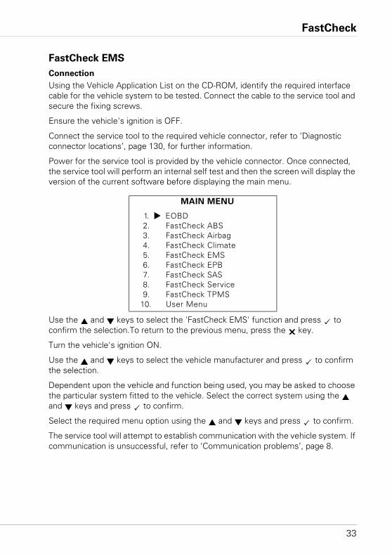
Power for the service tool is provided by the vehicle connector. Once connected, the service tool will perform an internal self test and then the screen will display the version of the current software before displaying the main menu.
Use the and keys to select the 'FastCheck EMS' function and press to confirm the selection.To return to the previous menu, press the key.
Turn the vehicle's ignition ON.
Use the and keys to select the vehicle manufacturer and press to confirm the selection.
Dependent upon the vehicle and function being used, you may be asked to choose the particular system fitted to the vehicle. Select the correct system using the and keys and press to confirm.
Select the required menu option using the and keys and press to confirm.
The service tool will attempt to establish communication with the vehicle system. If communication is unsuccessful, refer to ‘Communication problems’, page 8.
MAIN MENU
1. EOBD2. FastCheck ABS3. FastCheck Airbag4. FastCheck Climate5. FastCheck EMS6. FastCheck EPB7. FastCheck SAS8. FastCheck Service9. FastCheck TPMS
10. User Menu
FastCheck
34
Manufacturer Applications - EMS
General
As with all applications, the and keys are used to select the desired option, and the key used to confirm the selection.
Most manufacturer applications follow the same or similar procedures. Certain manufacturer applications require extra information. The following topics cover the extra information required to support these applications.
Audi, Seat, Skoda and Volkswagen Live Data (VAG Mode 8)
Live data can be viewed for all systems by selecting the appropriate Data Group for the vehicle under test (see data groups codes listed above). To view live data, select system from the 'Systems Menu' and follow on-screen instructions.
Whilst viewing any live data display group, another display group may be accessed by pressing the or keys. The description for each displayed live data item can be viewed by pressing the key.
FastCheck
35
Tips on the use of Basic Settings and Adaptation function
On replacement of a vehicle sensor, basic settings can be used to enable the ECU to re-learn quickly the operating conditions of the new sensor as opposed to learning the operating conditions over time. This is done by selection of display group 0 or the display group in which the sensor measured value would appear.
On replacement of a vehicle ECM with an existing (used) ECM, the adaptation function can be used to erase all previously learned values retuning the ECU to the factory default settings; this gives the ECM the chance of re-learning the operating conditions of the attached sensors. This is done by selection of adaptation channel 0 and then following the on screen instructions.
Actuators (VAG mode 3)
This function allows component activation (Injectors, Solenoid valves, Relays etc.) in the sequence determined by the ECM. The Technician can use this function to test the electrical circuit of available actuators or to investigate where faults lie when an actuator fails to actuate.
For the Actuators function to perform appropriately, the ignition must be switched on with the engine not running. If actuation is required for the ENG Electronics 1,2 or 3, the engine temperature must be at a minimum of 80°C (176°F) to ensure that all of the injectors are activated. For each actuator, the activation process will run for approximately 1 minute unless the test process is advanced to the next actuator by pressing the key to accept.
Preliminary requirements
1. Ignition On, Engine not running.
2. Engine temperature at a minimum of 80°C (176°F). (If applicable)
3. The ECM is functioning correctly.
4. The required channel is available.
FastCheck
36
Performing Actuator test
1. Connect the scan tool to the vehicle's diagnostic socket.
2. Select the particular system (i.e. ENG Electronics1) from the SYSTEM MENU and wait for diagnostic communication.
3. From the FUNCTIONS MENU select ' Actuators' and follow the screen prompt.
4. After the first actuator has been actuated, the actuator identification will be displayed on the scan tool display.
5. To activate the next actuator in the pre-determined sequence, press the key.
6. When the last actuator in the sequence is activated the scan tool will then display "END".
7. If the activation process is to be repeated, the engine must be started such that the ECM detects an engine speed greater than 300 rpm.
NOTE: The actuator function can be performed on any ECM that has actuators associated with it. During the activation process the electric fuel pump will run continuously. For each ECM the sequence and duration of each activation is pre-determined by the ECM.
Basic Settings (VAG mode 4)
This function allows the technician to view and change base/learned values relating to ignition timing, idle speed, mixture, etc. The Basic settings function can also be used to ensure that the ECM can adapt or re-learn the engine operating conditions within a short period of time.
Based on the engine code, some ECMs do not have provisions for adjustment of basic settings using a diagnostic tool. For these ECMs, the operating parameters are pre-stored in the ECM and adapt as the engine operational conditions change.
If the learned values are erased the ECM will revert to the default values for each of the operating parameters, which may not match the engine current operating status. This may result in temporary poor engine performance. If the engine is operated over a long period, the ECM will re-learn and adapt to the engine. However, with the use of a diagnostic tool the ECM can be made to adapt to the engine within minutes.
FastCheck
37
Preliminary requirements
1. Vehicle stationary. Hand brake/parking brake on.
2. Engine running at idle.
3. Accelerator pedal at rest.
4. Fault memory must be erased.
5. All electrical consumers switched off. (Coolant fan must not run during basic settings).
6. Air conditioning system must be switched off.
7. Engine temperature at a minimum of 80°C (176°F).
After initiating basic settings
After initiating basic settings the scan tool will:
1. Switch off A/C compressor.
2. Switch off the EVAP canister purge regulator system.
3. Stabilise idle speed.
4. Stabilise ignition speed.
Performing basic settings
1. Connect the scan tool to the vehicle's diagnostic socket.
2. Select 'ENG Electronics'1 from the SYSTEM MENU and wait for diagnostic communication.
3. From the FUNCTIONS MENU select 'Read DTCs' and erase any existing fault codes.
4. Return to the FUNCTIONS MENU and select 'Basic settings' and enter display group 0. Press the key to display the stored data values.
5. Using the accelerator pedal, increase engine speed to slightly above idle speed for 5 seconds and then allow engine to idle for 2 to 3 minutes.
6. Check the scan tool display to ensure that the values are within the vehicle specifications based on the engine code.
If the displayed data is within the specification and the coolant fan has not run during the test, basic settings are complete. If the displayed data is out of range, rectify the fault and re-start the process.
FastCheck
38
Re-Coding (VAG Mode 7)
Provided that a module can be re-coded, this mode allows for the coding of a replacement control module or changing previously stored incorrect coding. Coding is stored either as 7-bit (0000000 - 1048575) or 5-bit (00000 - 32767). New code numbers can be entered via the scan tool.
Once the scan tool has established a data link with a module it will evaluate the module coding. Dependent on the protocol used, KeyWord 1281, KeyWord 2000 or CAN, the module will indicate whether it can be re-coded. KeyWord 1281 protocol identification will display P-M-C and the Work Shop Code (WSC) 00000 if re-coding is not supported. KeyWord 2000 or CAN protocols will display 'Function not supported' if re-coding not possible.
Where re-coding is supported, on-screen instructions are displayed to guide the user through re-coding. The scan tool recognizes 20 or 15 bit coding and will modify input requirements accordingly.
WARNING: Before re-coding a module, record original code number in case
new code number is not accepted.
As an example, an instrument panel control module has a code 01402 that has the following meaning:• 01 - Brake pad wear sensor - warning active• 4 - UK 24 hr. clock and odometer in miles for cluster (2000+)• 3 - No service interval (only for 2002+ models)• 1 - Distance impulse number (k value)
Re-coding an ECM
Preliminary Requirements
1. Ignition on, engine not running
2. ECM supports re-coding
3. Scan tool
FastCheck
39
Re-coding Procedure
1. Connect the scan tool to the vehicle’s data link connector.
2. From the 'Systems Menu', select relevant control module and wait for data link to be established.
3. From the 'Functions Menu', select 'Re-coding' - follow on-screen instructions.
NOTE: KeyWord 1281 protocol requires 5 digits, including leading zeroes as appropriate, KeyWord 2000 and CAN protocol requires 7 digits, including leading zeroes.
4. Ensure that the correct number sequence is entered and if accepted by the module the display will indicate the new code, if code is incorrect the original code is retained and an error message is displayed.
NOTE: There is no restriction on the number of attempts allowed to re-code a module.
The original code is stored in the module data and is displayed by the scan tool on establishing a data link.
WARNING: The original code can only be restored by re-entering the code
following the procedure above.
Adaptation (VAG Mode 10)
This function not only allows the resetting of service intervals, but also certain values and settings in the control modules that supports it, i.e. gauge values, mixture trims, etc. Adaptation is carried out by selecting a channel number. There are three steps to changing adaptation values:
1. Read adaptation
2. Test adaptation
3. Save adaptation
Read Adaptation
Read adaptation will read and display adaptation data from a selected ECM adaptation channel. When a channel number is selected by the technician and the
key has been pressed the ECM will respond with the value that is currently stored in that channel.
Test Adaptation
Test adaptation allows the newly entered adaptation value to be tested on the engine in order to achieve the correct setting for the required running condition. When the new adaptation value is entered and the key is pressed the ECM temporarily stores the value. If a measured value block is assigned to the channel it will be displayed.
FastCheck
40
Save Adaptation
Save adaptation allows the new adaptation value to be stored in the selected channel. If the technician decides to permanently store the new adaptation value to the ECM, after pressing the key, the new value is stored in the channel and is then used by the engine.
Preliminary requirements
1. Ignition On, Engine not running.
2. The ECM is functioning correctly.
3. The required channel is available.
Performing Adaptation test
1. Connect the scan tool to the vehicle's diagnostic socket.
2. Select the required ECM from the SYSTEM MENU (the selection should be based on the type of adaptation that needs to be performed) follow the screen prompts and wait for diagnostic communication.
3. From the FUNCTIONS MENU select 'Adaptation', then select the 'Manual Reset' option (if applicable). Enter the channel number and follow the on-screen instructions.
4. If a measured value block is assigned to the channel, by pressing the arrow, the scan tool will display the measured value.
5. If the technician needs to change the current value, by pressing the key the technician would be able to enter the data in a five digit format. For example, if the number 15 needs entering the technician must enter 00015 using the , and key where appropriate.
6. Having tested the new value the Technician can save the new value by pressing the key.
7. The scan tool will then display the new value that is stored in the selected channel.
8. If the technician needs to clear all learned values and revert back to the baseline values, channel number '0' needs to be entered when prompted.
NOTE: Adaptation function should be used by Technicians who are aware of the results of changing baselines/learn values to the engine operations.
FastCheck
41
Login to ECM (VAG Mode11)
Some ECMs may require a valid login code to be entered before allowing some actions such as re-coding, adaptation values, coding cruise control, A/C etc.
Each vehicle control module has a unique login code that is stored in the 'Vehicle Factory Repair Manual' or can be obtained from a VAG dealer. The login code is a 5 digit number between 0 and 65535 and is entered via the scan tool. If the login is accepted 'Code Accepted' is displayed, if, however, the login code is incorrect the response depends upon the protocol:• KeyWord 1281 - Communication between the scan tool and the module will be
broken and the message 'Datalink error, Login lost - Please check the code entered then retry' (the control module will need to be reset by switching the ignition off and then on again).
• KeyWord 2000 & CAN - an error message is displayed and communications are maintained
Login to an ECM
Preliminary Requirements
1. Ignition on - engine not running
2. ECM supports login
3. Scan tool
Login Procedure
1. Connect the scan tool to the vehicle’s data link connector.
2. From 'Systems Menu' select relevant ECM.
3. From 'Functions Menu' select 'Login ECM'.
4. Follow on-screen instructions and enter login code, including any leading zeroes.
5. On acceptance of the code 'Code accepted' will be displayed, if not an appropriate error message will be displayed.
NOTE: There is no restriction on the number of attempts made to enter the login code, however, some ECMs may break the datalink requiring the ignition to be switched off for approximately 2 minutes before re-establishing communications.
FastCheck
42
BMW
NOTE: To switch the ignition ON procedure for vehicles fitted with a start/stop, insert the remote key-fob fully into the ignition slot then press the start/stop button once (without any foot pedals depressed).
The vehicle's diagnostic connector (20-pin round connector) is always found in the engine compartment. If the vehicle is fitted with a J1962 diagnostic connector, this can usually be located in the driver's footwell behind a cover.
NOTE: If the BMW vehicle under test has both the round (20 pin) diagnostic connector and the J1962 (16 pin) connector, the round connector should always be used to access information via the BMW application and the J1962 connector should be used to access data via the EOBD application (ensure the cap is fitted to the 20-pin connector). If the cap is not fitted, the J1962 connector will not function correctly.
NOTE: The Multiplexer cable (YTD965) or the CAN Converter (YTD960) harness must be used for any diagnostics on the following vehicles:
BMW 1 series (E81/E87)
BMW 3 series (E90/E91/E92/E93)
BMW 5 series (E60/E61)
BMW 6 series (E63/E64)
BMW 7 series (E65)
Citroen and Peugeot
Particle Filter (FAP)
PSA were the first Vehicle manufacturer to introduce the Particle Emissions Filter (PEF or FAP). The purpose of the filter is to considerably reduce emissions from diesel injected engines.
As well as the standard functions such as Read/Clear DTCs and Live Data there are a number of configuration functions available for the Particle Filter and the Additive ECU.
FastCheck
43
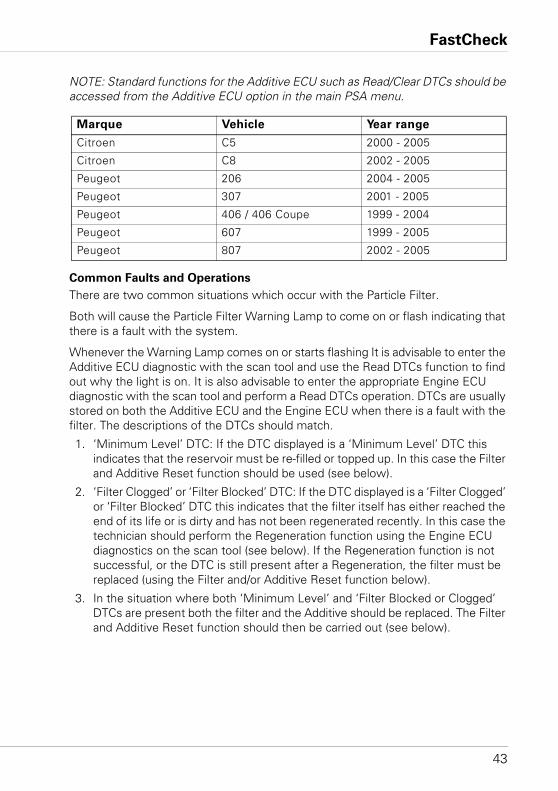
NOTE: Standard functions for the Additive ECU such as Read/Clear DTCs should be accessed from the Additive ECU option in the main PSA menu.
Common Faults and Operations
There are two common situations which occur with the Particle Filter.
Both will cause the Particle Filter Warning Lamp to come on or flash indicating that there is a fault with the system.
Whenever the Warning Lamp comes on or starts flashing It is advisable to enter the Additive ECU diagnostic with the scan tool and use the Read DTCs function to find out why the light is on. It is also advisable to enter the appropriate Engine ECU diagnostic with the scan tool and perform a Read DTCs operation. DTCs are usually stored on both the Additive ECU and the Engine ECU when there is a fault with the filter. The descriptions of the DTCs should match.
1. ‘Minimum Level’ DTC: If the DTC displayed is a ‘Minimum Level’ DTC this indicates that the reservoir must be re-filled or topped up. In this case the Filter and Additive Reset function should be used (see below).
2. ‘Filter Clogged’ or ‘Filter Blocked’ DTC: If the DTC displayed is a ‘Filter Clogged’ or ‘Filter Blocked’ DTC this indicates that the filter itself has either reached the end of its life or is dirty and has not been regenerated recently. In this case the technician should perform the Regeneration function using the Engine ECU diagnostics on the scan tool (see below). If the Regeneration function is not successful, or the DTC is still present after a Regeneration, the filter must be replaced (using the Filter and/or Additive Reset function below).
3. In the situation where both ‘Minimum Level’ and ‘Filter Blocked or Clogged’ DTCs are present both the filter and the Additive should be replaced. The Filter and Additive Reset function should then be carried out (see below).
Marque Vehicle Year range
Citroen C5 2000 - 2005
Citroen C8 2002 - 2005
Peugeot 206 2004 - 2005
Peugeot 307 2001 - 2005
Peugeot 406 / 406 Coupe 1999 - 2004
Peugeot 607 1999 - 2005
Peugeot 807 2002 - 2005
FastCheck
44
Regeneration
Regeneration is managed by the EMS system. Entry to this function must therefore be done by selecting EMS and the appropriate system.
The function of Regeneration is to burn particles which have been caught in the filter in order to clean it. This is achieved by raising the temperature inside the filter to around 450°C. An additive is used to reduce the natural combustion temperature of the particles to around 450°C.
Under normal driving conditions regeneration takes place automatically, every 400 to 500 km (250 to 300 miles). However, some driving conditions, such as urban driving, are unfavourable to automatic regeneration. In these cases it is necessary to force a Regeneration using this function.
The following is recommended practice for forced Regeneration:
1. The exhaust and its direct environment MUST be clean.
2. Exhaust gas extraction devices must NOT be connected to the exhaust pipe.
3. No-one should go near the exhaust pipe during Regeneration.
4. The engine must be running and the engine coolant temperature must be above 70°C for a successful regeneration to take place.
5. The fuel tank must be at least ¼ full.
NOTE: The operation proceeds as follows:• Start the engine• Sending of the command via scan tool• Wait 2 minutes• The ECU increases engine speed to 4000 rpm with post-injection• The ECU returns the engine speed to idle for 30 seconds• The ECU increases engine speed to 3000 rpm to create a balance.
The vehicle must be in good condition (oil level/quality, belt tension/quality)
or damage may occur when the Regeneration function is executed.
The scan tool will guide the technician through the process.
The technician should perform a Clear DTCs function followed by a Read DTCs function after a Regeneration to check the validity of the process. In some cases the filter may have been damaged prior to Regeneration. A ‘Filter Blocked’ or ‘Filter Clogged’ DTC being present after a Regeneration indicates that the filter has reached the end of its life and must be replaced (use the Additive Reset function below for this operation).
FastCheck
45
NOTE: When the technician is asked to start the engine the scan tool may reset depending on the state of the vehicle's battery. If this occurs the engine should be kept running and the technician should re-start the scan tool and re-select the 'Regeneration' option.
Filter and Additive (Reservoir) Reset
Entry to the Reset function is done via the Additive ECU option.
There are two variants of the Additive ECU:
1. ADDITIF_FAP
2. ADDGO2
The scan tool should automatically identify which variant is fitted to the vehicle by reading the ECU part number. If the part number is unknown to the scan tool the technician will be asked to select the correct ECU.
As a rough guide the early FAP systems use ADDITIF_FAP (1999 – 2002) and the later FAP systems use ADDGO2 (2002 onwards).
ADDITIF_FAP (1999 – 2002)
There is one option in the Reset menu which performs both a reset of the Filter and reset of the Additive (reservoir).
FILTER RESET:
This function is used whenever the amount of additive in the reservoir falls below the pre-determined minimum level. It can also be used when the Particle Filter itself is changed (this usually coincides with the re-fill of the reservoir). If the filter does need to be changed it should be done prior to carrying out this function and, if applicable, prior to carrying out an additive change. There are two types of additives used in these systems, DPX42 is the original additive used. A full tank of DPX42 will last for 50,000 miles. EOLYS176 is a newer additive. A full tank of EOLYS176 will last for approximately 75,000 miles. When the additive has reached the minimum level the Particle Filter Warning Lamp will start to flash on the dashboard of the vehicle informing the driver that the additive must be topped up. A fault code (DTC) is also stored on both the Engine ECU and the Additive ECU.
If the Particle Filter needs to be changed the Particle Filter Warning Lamp will also start to flash on the dashboard of the vehicle
A fault code (DTC) is also stored on both the Engine ECU and the Additive ECU, usually describing the problem as ‘Filter clogged’ or ‘Filter blocked’. Sometimes performing a ‘Regeneration’ (see above) may unclog or unblock the filter. If it does not then the filter must be changed.
This function is designed to be used AFTER the technician has changed the filter and/or topped up the additive reservoir. Additives can be purchased from the
FastCheck
46
manufacturer’s parts department. This function resets the 'Quantity of Additive' in the 'Reservoir and Filter' value stored in the Additive CM to zero. The technician must then follow the instructions precisely to enable the CM to re-learn the value.
IMPORTANT: The scan tool instructs the technician to perform the following:
1. Switch ignition OFF.
2. Remove the diesel filler cap.
3. Wait for 10 seconds.
4. Replace the diesel filler cap.
5. Switch the engine on and run for 1 minute.
6. Switch the engine off and wait for 4 minutes.
7. Activate nothing on the vehicle during this time, especially not the key fob!
8. Switch the ignition ON.
9. Use the scan tool to Clear DTCs in the Additive ECU.
10. Use the scan tool to Clear DTCs in the Engine ECU.
The sequence of events MUST be started within 10 seconds of the scan tool displaying the "To complete reset do the following..." message. If it is not performed in the correct order or started within 10 seconds the vehicle will not re-learn the new Additive value correctly and the Particle Filter warning lamp will continue to flash or stay on. If this occurs the function must be re-selected on the scan tool and the procedure re-started.
ADDGO2 (2002 onwards)
There are two options in the Reset menu:
RESERVOIR RESET:
This function is used whenever the amount of additive in the reservoir falls below the pre-determined minimum level. There are two types of additive used in these systems, DPX42 is the original additive used. A full tank of DPX42 will last for 50,000 miles. EOLYS176 is a newer additive. A full tank of EOLYS176 will last for approximately 75,000 miles. When the additive has reached the minimum level the Particle Filter Warning Lamp will start to flash on the dashboard of the vehicle informing the driver that the additive must be topped up. A fault code (DTC) is also stored on both the Engine ECU and the Additive ECU.
This function is designed to be used AFTER the technician has topped up the additive reservoir. Additives can be purchased from the manufacturer’s parts department. This function resets the 'Quantity of Additive' in the reservoir value stored in the Additive CM to zero. The technician must then follow the instructions precisely to enable the CM to re-learn the value.
FastCheck
47
IMPORTANT: The scan tool instructs the technician to perform the following:
1. Switch ignition OFF.
2. Remove the diesel filler cap.
3. Wait for 10 seconds.
4. Replace the diesel filler cap.
5. Switch the engine on and run for 1 minute.
6. Switch the engine off and wait for 4 minutes.
7. Activate nothing on the vehicle during this time, especially not the key fob!
8. Switch the ignition ON.
9. Use the scan tool to Clear DTCs in the Additive ECU.
10. Use the scan tool to Clear DTCs in the Engine ECU.
The sequence of events MUST be started at within 10 seconds of the scan tool displaying the "To complete reset do the following..." message. If it is not performed in the correct order or started within 10 seconds the vehicle will not re-learn the new Additive value correctly and the Particle Filter warning lamp will continue to flash or stay on. If this occurs the function must be re-selected on the scan tool and the procedure re-started.
FILTER RESET:
This function is used when the Particle Filter itself has been changed. If the filter does need to be changed it should be done prior to carrying out this function and, if applicable, prior to carrying out an additive change. If the Particle Filter does need to be changed the Particle Filter Warning Lamp will start to flash on the dashboard of the vehicle. A fault code (DTC) is also stored on both the Engine ECU and the Additive ECU, usually describing the problem as ‘Filter clogged’ or ‘Filter blocked’. Sometimes performing a ‘Regeneration’ (see above) may unclog or unblock the filter. If it does not then the filter must be changed. This function is designed to be used AFTER the technician has changed the filter.
This function resets the 'Quantity of Additive in the Filter' value stored in the Additive CM to zero. The technician must then follow the instructions precisely to enable the CM to re-learn the value.
FastCheck
48
IMPORTANT: The scan tool instructs the technician to perform the following:
1. Switch ignition OFF.
2. Remove the diesel filler cap.
3. Wait for 10 seconds.
4. Replace the diesel filler cap.
5. Switch the engine on and run for 1 minute.
6. Switch the engine off and wait for 4 minutes.
7. Activate nothing on the vehicle during this time, especially not the key fob!
8. Switch the ignition ON.
9. Use the scan tool to Clear DTCs in the Additive ECU.
10. Use the scan tool to Clear DTCs in the Engine ECU.
The sequence of events MUST be started at within 10 seconds of the scan tool displaying the "To complete reset do the following..." message. If it is not performed in the correct order or started within 10 seconds the vehicle will not re-learn the new Additive value correctly and the Particle Filter warning lamp will continue to flash or stay on. If this occurs the function must be re-selected on the scan tool and the procedure re-started.
WARNING: The additive is harmful and should not come into contact with the
technician’s skin.
NOTE: The additive is now sold as a kit which includes a device to insert the additive into the reservoir. Some kits contain the additive in a plastic bag which can be placed directly into the reservoir.
Additive Type
There are two different types of Additive used:• DPX42• EOLYS176 (DPX10)
Both have different properties, DPX42 is the original additive used by PSA. A full tank of DPX42 lasts 50,000 miles. EOLYS176 (DPX10) is an improved additive which will last for 75,000 miles.
IMPORTANT: A vehicle which uses DPX42 can not be upgraded to EOLYS176 (DPX10) and vice versa. This function is used when a new Additive ECU is installed in a vehicle. The new ECU is programmed with the additive type that the vehicle uses.
There are two ways to visually determine the type of Additive used. This depends on the model.
FastCheck
49
For Peugeot 406, Peugeot 607, Peugeot 807, Citroen C5 and Citroen C8:
Check the colour of the Additive reservoir cap. • For EOLYS176 (DPX10) the colour will be Black with a green ring.• For DPX42 the colour will be Black with a white ring.
For Peugeot 307 and Peugeot 206:
Check the colour of the click-on connectors on the Additive reservoir and Particle filter.• For EOLYS176 (DPX10) the colour will be Black with a green ring.• For DPX42 the colour will be Black with a white ring.
IMPORTANT: • Use these two additives exclusively. The use of any other additive will cause the
system to malfunction.• Always use new, clean additive. There is a risk of the additive injector seizing if
dirty or old additive is used. • Never mix the two additives.• It is impossible to differentiate visually between the two additives, as their
appearance is identical.
WARNING: The additive is harmful and should not come into contact with the
technician’s skin.
Control Unit Replacement
This function refers to the Additive ECU, and must be accessed via the Additive ECU option.
When a new Additive ECU is installed in a vehicle it must be programmed with the current quantity of additive in the reservoir.
Before using this function ensure that:
1. You know the ‘quantity of additive’ present in the reservoir. You can do this by reading the value from the old Additive ECU while it is still installed (using Live Data ‘Quantity Of Additive’ reading). If you have already removed the old ECU you can obtain the value by selecting the correct EMS system fitted to the vehicle and reading the value from Live Data.
2. The new Additive ECU has been installed.
The technician will be asked to input the ‘Quantity Of Additive’ value which will then be written to the new ECU.
FastCheck
50
Inter-changeability
As stated previously it is not possible to upgrade a vehicle which uses additive type DPX42 to EOLYS176 (DPX10).
It is possible however to install an additive ECU with Additive Type mapping DPX42 or EOLYS176 (DPX10) in order to replace an ECU with mapping DPX42 is possible on condition that the following operations are carried out:
1. Follow the process for ‘Control Unit Replacement’ above.
2. Use the ‘Additive Type’ menu option to set the additive type to DPX42.
When installing an additive ECU with Additive Type mapping EOLYS176 (DPX10) in order to replace an ECU with mapping EOLYS176 (DPX10) the following operations must be carried out:
1. Follow the process for ‘Control Unit Replacement’ above.
2. Use the ‘Additive Type’ menu option to set the additive type to EOLYS176.Use the ‘Additive Type’ menu option to set the additive type to EOLYS176.
Reset Adaptions
The purpose of the Reset Adaptions function is to reset the base values stored in the CM's memory to a zero state. These base values vary according to the age of the engine and the purpose of them is to maintain a perfectly adjusted engine system. After a reset the CM will re-learn the values, either automatically or by the technician performing a number of steps.
The function should be used when important components have been replaced. If the base values are not reset the engine will experience stalling and hesitation problems.
The process for Reset Adaptions varies from CM to CM. The technician may have to go through several steps to successfully complete the reset and re-learn procedure. On systems which require a diagnostic command the scan tool will attempt to guide the technician through these steps, but due to battery voltage dips during engine cranking the scan tool may reset before a procedure has been completed.
See manufacturers procedures for each individual CM.
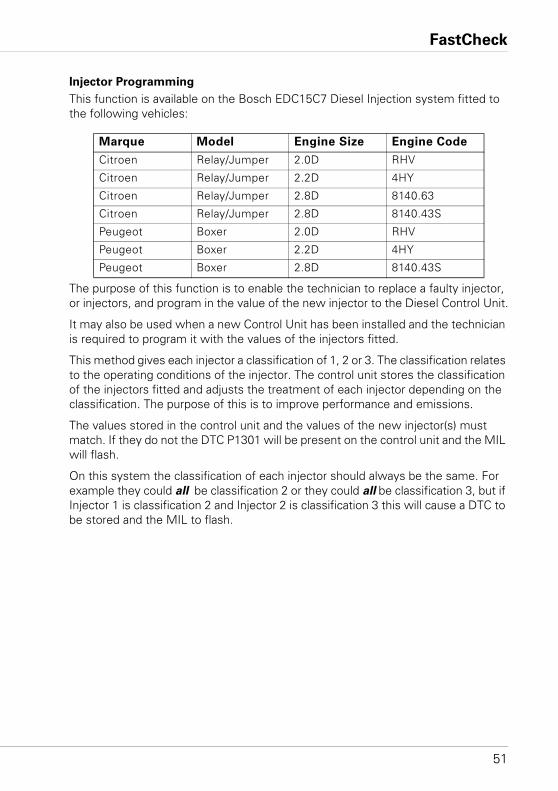
FastCheck
51
Injector Programming
This function is available on the Bosch EDC15C7 Diesel Injection system fitted to the following vehicles:
The purpose of this function is to enable the technician to replace a faulty injector, or injectors, and program in the value of the new injector to the Diesel Control Unit.
It may also be used when a new Control Unit has been installed and the technician is required to program it with the values of the injectors fitted.
This method gives each injector a classification of 1, 2 or 3. The classification relates to the operating conditions of the injector. The control unit stores the classification of the injectors fitted and adjusts the treatment of each injector depending on the classification. The purpose of this is to improve performance and emissions.
The values stored in the control unit and the values of the new injector(s) must match. If they do not the DTC P1301 will be present on the control unit and the MIL will flash.
On this system the classification of each injector should always be the same. For example they could all be classification 2 or they could all be classification 3, but if Injector 1 is classification 2 and Injector 2 is classification 3 this will cause a DTC to be stored and the MIL to flash.
Marque Model Engine Size Engine Code
Citroen Relay/Jumper 2.0D RHV
Citroen Relay/Jumper 2.2D 4HY
Citroen Relay/Jumper 2.8D 8140.63
Citroen Relay/Jumper 2.8D 8140.43S
Peugeot Boxer 2.0D RHV
Peugeot Boxer 2.2D 4HY
Peugeot Boxer 2.8D 8140.43S
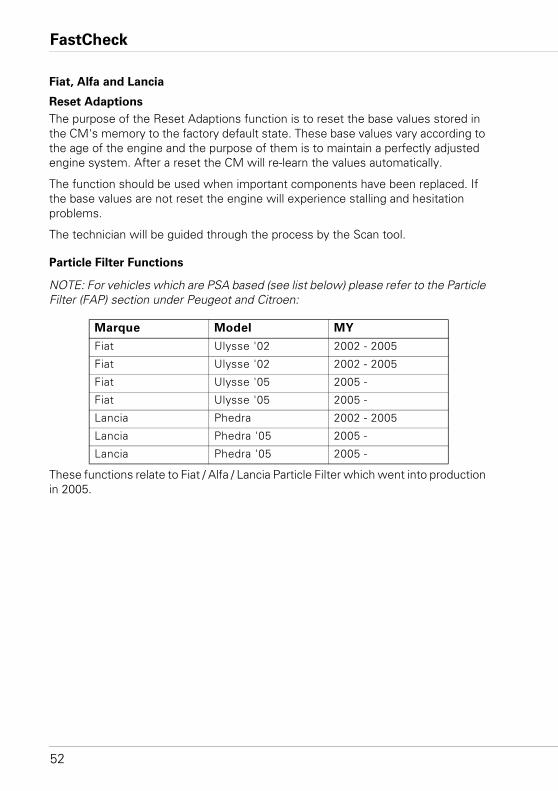
FastCheck
52
Fiat, Alfa and Lancia
Reset Adaptions
The purpose of the Reset Adaptions function is to reset the base values stored in the CM's memory to the factory default state. These base values vary according to the age of the engine and the purpose of them is to maintain a perfectly adjusted engine system. After a reset the CM will re-learn the values automatically.
The function should be used when important components have been replaced. If the base values are not reset the engine will experience stalling and hesitation problems.
The technician will be guided through the process by the Scan tool.
Particle Filter Functions
NOTE: For vehicles which are PSA based (see list below) please refer to the Particle Filter (FAP) section under Peugeot and Citroen:
These functions relate to Fiat / Alfa / Lancia Particle Filter which went into production in 2005.
Marque Model MY
Fiat Ulysse '02 2002 - 2005
Fiat Ulysse '02 2002 - 2005
Fiat Ulysse '05 2005 -
Fiat Ulysse '05 2005 -
Lancia Phedra 2002 - 2005
Lancia Phedra '05 2005 -
Lancia Phedra '05 2005 -
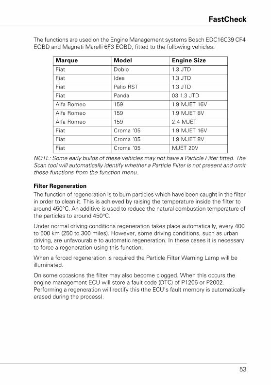
FastCheck
53
The functions are used on the Engine Management systems Bosch EDC16C39 CF4 EOBD and Magneti Marelli 6F3 EOBD, fitted to the following vehicles:
NOTE: Some early builds of these vehicles may not have a Particle Filter fitted. The Scan tool will automatically identify whether a Particle Filter is not present and omit these functions from the function menu.
Filter Regeneration
The function of regeneration is to burn particles which have been caught in the filter in order to clean it. This is achieved by raising the temperature inside the filter to around 450°C. An additive is used to reduce the natural combustion temperature of the particles to around 450°C.
Under normal driving conditions regeneration takes place automatically, every 400 to 500 km (250 to 300 miles). However, some driving conditions, such as urban driving, are unfavourable to automatic regeneration. In these cases it is necessary to force a regeneration using this function.
When a forced regeneration is required the Particle Filter Warning Lamp will be illuminated.
On some occasions the filter may also become clogged. When this occurs the engine management ECU will store a fault code (DTC) of P1206 or P2002. Performing a regeneration will rectify this (the ECU’s fault memory is automatically erased during the process).
Marque Model Engine Size
Fiat Doblo 1.3 JTD
Fiat Idea 1.3 JTD
Fiat Palio RST 1.3 JTD
Fiat Panda 03 1.3 JTD
Alfa Romeo 159 1.9 MJET 16V
Alfa Romeo 159 1.9 MJET 8V
Alfa Romeo 159 2.4 MJET
Fiat Croma ‘05 1.9 MJET 16V
Fiat Croma ‘05 1.9 MJET 8V
Fiat Croma ‘05 MJET 20V
FastCheck
54
The following is recommended practice for forced regeneration:
1. The exhaust and its direct environment MUST be clean.
2. Exhaust gas extraction devices must NOT be connected to the exhaust pipe.
3. No-one should go near the exhaust pipe during regeneration.
4. The engine must be running and the engine coolant temperature must be above 70°C for a successful regeneration to take place.
5. The fuel tank must be at least ¼ full.
The Scan tool will guide the technician through the process.
NOTE: When the technician is asked to start the engine the Scan tool may reset depending on the state of vehicle’s battery. If this occurs the engine should be kept running and the technician should re-start the Scan tool and re-select the ‘Regeneration’ option.
Filter Replacement
This procedure must be performed AFTER the particle filter has been replaced. Parameters stored in the ECU relating to the condition and lifetime of the particle filter, are reset by this function.
After initialising the parameters in the ECU the regeneration process detailed above is performed. For this reason all of the recommended practice points in the above section are also applicable to this function.
The Scan tool will guide the technician through the process.
NOTE: When the technician is asked to start the engine the Scan tool may reset depending on the state of vehicle’s battery. If this occurs the engine should be kept running and the technician should re-start the Scan tool and re-select the ‘Regeneration’ option.
Oil Change
This procedure must be performed AFTER an engine oil change has taken place. Parameters stored in the ECU relating to the condition and lifetime of the Oil, are reset by this function.
The Scan tool will guide the technician through the process.
Pre-catalyser Replacement
This procedure must be performed AFTER the pre-catalyser has been replaced. Parameters stored in the ECU relating to the condition and ageing of the pre-catalyser, are reset by this function.
The Scan tool will guide the technician through the process.
FastCheck
55
Differential Pressure Sensor Replacement
This procedure must be performed AFTER the differential pressure sensor has been replaced. Parameters stored in the ECU relating to the pressure difference are reset by this function.
The Scan tool will guide the technician through the process.
Injector Programming
The purpose of this function is to enable the technician to replace a faulty injector, or injectors, and program in the value of the new injector to the Diesel Control Unit.
It may also be used when a new Control Unit has been installed and the technician is required to program it with the values of the injectors fitted.
The function is available on all Diesel Engine Management Systems from 2002 onwards.
There are two different methods for Injector Programming on FAL:
The early method gives each injector a classification of 1, 2 or 3. The classification relates to the operating conditions of the injector. The control unit stores the classification of the injectors fitted and adjusts the treatment of each injector depending on the classification. The purpose of this is to improve performance and emissions. The Scan tool has the ability to read out the current classification of the injectors and program in the new classification.
The newer method uses 9 digit alpha-numeric injector codes. These codes are stamped on the casing of each individual injector and held electronically in the control unit. The code is a result of calibration results and the results of tests ran on the injector at the time of production. This is an enhancement of the above method designed to combine the injector's structural characteristics with the control module's software and improve performance and emissions to a greater extent. This method is used on the remaining diesel systems. The Scan tool has the ability to read out the current injector codes and program in new injector codes.
In both cases the values stored in the control unit and the values of the new injector(s) must match. If they do not the DTC P1301 will be present on the control unit and the MIL will flash.
NOTE: On Bosch EDC15 CF3 (2.0 / 2.3 / 2.8) systems, fitted to the Fiat Ducato, the classification of all injectors should always be the same. For example they could all be classification 2 or they could all be classification 3, but if Injector 1 is classification 2 and Injector 2 is classification 3 this will cause a DTC to be stored and the MIL to flash.
The function is still invaluable because when a new injector is fitted (or a control unit replaced) the control unit must be programmed, via this function, with the injector class 2 value.
FastCheck
56
Ford
Self Test
The purpose of the self test is for the control module to run an internal test that will check the module inputs and outputs for fault conditions. The module will activate outputs and monitor inputs to determine faults such as open/short circuits etc. The self test should have been completed within a maximum of 30 seconds. After the completion of the self test then all of the control modules outputs are returned to their initial state.
Engine Management Guide
If there is doubt as to which engine management system is fitted to the vehicle under test but the vehicle has a J1962 connector (16-pin), examine the connector. If pins 2 and 10 are fitted, the vehicle is EEC V but if pins 3 and 11 are fitted, the vehicle is EEC IV - DCL.
NOTE: The Ford Galaxy 1.9 TDi with a VW engine is only accessible via the VAG application.
The older 2-pin and 3-pin connectors will require the red power lead and the black power lead to be connected to the car battery terminals to achieve power connection.
The scan tool will attempt to establish serial communications with the vehicle. Once established, follow the on-screen instructions for each test.
NOTE: If the ECU detects a fault then the live data may be set to a default value. Check the fault codes and rectify any problems before using the live data values.
Selection of Diagnostic System
Ford traditionally used EECIV (Electronic Engine Control, version 4) on all their vehicles from the early 1980s until the mid 1990s. The Ford diagnostic unit at this time was called a STAR tester, (Self Test Automatic Read-out). It only showed either a 2 or 3 digit code, which the technician looked up in a table to get the description. No live data or component tests were available.
Around 1994, Ford introduced a more advanced system called EECV (Electronic Engine Control, version 5). This system was only fitted to some vehicles. Ford then merged the two systems, which was known by various names. Amongst these are EECIV1/2, EECIV enhanced and DCL (Data Communications Link). For these systems Ford use the WDS (World Diagnostic System) diagnostic tool, these systems show live data and have limited component tests.
FastCheck
57
By 1998 all Ford vehicles had changed to the EECV system, except:• Those vehicles made in collaboration with the Japanese i.e. Maverick, Probe etc.
which use Japanese engine management systems. • The diesel Ford Galaxy which has a VW engine and uses the Bosch EDC system.• Transit 94 models which use the Lucas EPIC system.
Harnesses
Until 1981, Ford used a 3-pin oval shaped diagnostic socket located near the battery or wheel arch on most vehicles. From 1982 to 1993 a similar, but triangular 3-pin connector was used, which is always located in the engine compartment. In1994, Ford, in line with most other manufacturers, started using a J1962 16-pin harness located inside the passenger compartment. However Ford did not stop fitting the 3-pin socket under the bonnet until 1997 and also included a 2-pin connector. From 1998 Ford exclusively used another 16-pin socket with different pin terminations. For these applications, use harnesses YTD950 or Multiplexer cable (YTD965).
This leads to the difficulty in determining which harness and system Ford use on a particular vehicle, especially on model years 1994 to 1997.
NOTE: The Multiplexer cable (YTD965) or the CAN Converter (YTD960) harness must be used for any diagnostics on the following vehicles:
Fiesta VI (MY02 – MY07).
Fiesta VII (MY07 – present).
Focus II (MY04 – present).
Focus C-Max (MY03 – present).
Fusion (MY02 – present).
Galaxy III (MY06 – present).
Ka II (MY08 – present).
Kuga (MY08 – present).
Mondeo IV (MY07 – present).
S-Max (MY06 – present).
Transit (MY06 – present).
Transit Connect (MY02 – present).
The Multiplexer cable (YTD965) or the CAN Converter (YTD960) harness may also be used with all other 16-pin Ford vehicles.
FastCheck
58
Systems
From the late 1970s to the early 1980s Ford used a basic 2 digit system of EECIV, sometimes called EECIV LED or EECIV basic. This system used the 3-pin oval connector.
From the early 1980s Ford improved the systems and used the 3-pin triangular connector. This is always coloured black with a red protective cover.
When Ford introduced newer systems from 1994, many vehicles had 3-pin and 16-pin connectors fitted, however, only one of them would be connected to the ECM, depending on the Engine Management system used.
1994 - 1997 MY vehicles
Unfortunately there is no easy way of determining which system is fitted to these vehicles, as it depends on the system Ford used: EECIV, DCL or EECV.
Firstly check under the bonnet and see if a 3-pin connector is fitted. If so connect the scan tool using the relevant harness and select one of the EECIV systems from the menu, (not EECIV basic). Generally the older CVH engines use 2 digit codes. The Zetec engines generally use 3 digit codes. DCL and EECV systems never use the 3 pin connector.
DCL system uses either the 2-pin connector or the 16-pin connector.
NOTE: The DCL system is a variant of EECIV system.
The next step is to check for a 2-pin connector often fitted near the bonnet hinge. If present, connect the 2-pin harness and select DCL from the menu.
NOTE: EECIV and EECV never use the 2-pin connector.
If neither of these connectors are present or connection cannot be made to the vehicle using them, check in the passenger compartment for a J1962 16-pin connector. This is usually located at the bottom of the 'A' frame pillar, in the passenger footwell or under the steering wheel. If present, this connector will only use either the DCL or EECV systems.
NOTE: EECIV and EECV never use this harness.
If this will not connect to the vehicle, use the Multiplexer cable (YTD965) or the EOBD (J1962) cable (YTD950) and select EECV from the menu.
NOTE: Only EECV uses this harness.
FastCheck
59
Troubleshooter:
• On some systems a message will appear on screen "Please wait maximum 2 minutes". If the vehicle has not responded in this time the incorrect system or harness has been selected.
• Ford often use grease in their diagnostic sockets to avoid corrosion. This may need to be cleared from the socket to get a good electrical connection.
• When using the 3-pin triangular socket, the harness must be heard to 'click' into the socket, otherwise connection to the vehicle cannot be guaranteed. This is often a problem if the protective cover is missing and debris is trapped inside, preventing the harness from connecting correctly.
EEC V Menu
Select the type of engine fitted to the vehicle then follow the on-screen instructions:
For a diesel vehicle, the type of engine can usually be found on the plastic engine cover. To use a petrol variant the Petrol option should be selected.
If the Petrol option has been selected the following options will be provided:
1. Read DTCs
2. Clear DTCs
3. Live Data
4. Freeze Data
5. Continuous Tests
6. Output Test
7. KOEO Test
8. KOER Test
9. Read VIN
For help on freeze data and continuous tests, refer to the EOBD section of this document.
Output Test - Circuit Tests
The ignition must be on and the engine off. "Test in Progress" will be displayed. The test will automatically exit after 20 seconds for safety.
KO EO Test - Key On/Engine Off Self Test
This test is programmed into the ECU. It is to be carried out with the ignition on but engine off. Switch off all ancillary items e.g. Heaters, Aircon etc. "Performing test Please wait" will be displayed whilst the test is being performed. After the test has been completed the test results will be requested and the fault codes displayed.
FastCheck
60
KO ER Test - Key On/Engine Running Self Test
This test is similar to the KO EO test but with the engine running. Ensure the engine is at the correct operating temperature and follow the instructions on the display otherwise incorrect DTCs will be reported.
NOTE: For both KO EO and KO ER, the test results reported do not necessarily indicate a faulty component or system. Some fault codes reported may be for components or systems not fitted to the vehicle. A fault may also be reported if the test was performed with the system in an incorrect state (i.e. Power steering not operated during the test when requested or the Aircon turned on). All peripheral items should be turned off at the start of the test, e.g. heaters fans and Aircon.
Read VIN - Read the Vehicle Identification Number stored in the ECU
This will attempt to read the VIN from the ECU if it is supported/available.
Injector Programming (TDCi Engines)
This function is required by service centres when an Injector needs to be replaced, or there is a driveability problem.
For 1.8 TDCi and 2.0 TDCi engines the each injector has a 16-digit calibration code stamped on the body.
For 1.6 TDCi engines the each injector has an 8-digit calibration code stamped on the body.
These codes relate to the electrical and structural characteristics of each injector, which are defined during production. The PCM must know the calibration codes for each injector in order to treat and operate the injectors in the correct manner. This helps to reduce emissions and improve performance. The code must be programmed in by communicating and downloading the code into the PCMs memory.
There are three common situations which demand this function.
1. After Injector replacement.
2. Fuel injection system ‘calibration’.
3. To cure driveability problems. Lack of power, black smoke and the presence of DTCs P2336, P2337, P2338 can often be fixed by re-entering the existing 4 injector codes.
FastCheck
61
Injector Programming is used on the following vehicles:
NOTE:• On earlier model years (approx pre-2003) it is not possible to read the actual
injector codes. On these vehicles you will see ’00 00 00 00 00 00 00 00’ or ‘FF FF FF FF FF FF FF FF’ or a mixture.
• After entering an injector code the fuel system will initially run without any pilot injection sequence. The car must be driven for a few miles to correct this.
The codes of the ORIGINAL injectors fitted to vehicle can be found on a label, which is fitted to the side of the engine or on the engine rocker top (if it has not yet been removed).
Model Engine MY
Fiesta 1.6 TDCi 2004 -
Focus 1.8 TDCi 2001 - 2005
Focus (new shape) 1.6 TDCi 2005 -
Focus C-Max 1.6 TDCi 2005 -
Mondeo 2.0 TDCi 2000 - 2006
Mondeo 2.2 TDCi 2005 - 2006
Transit 2.0 TDCi 2000 - 2005
Transit 2.4 TDCi 2000 - 2005
Transit Connect 1.8 TDCi 2002 - 2006
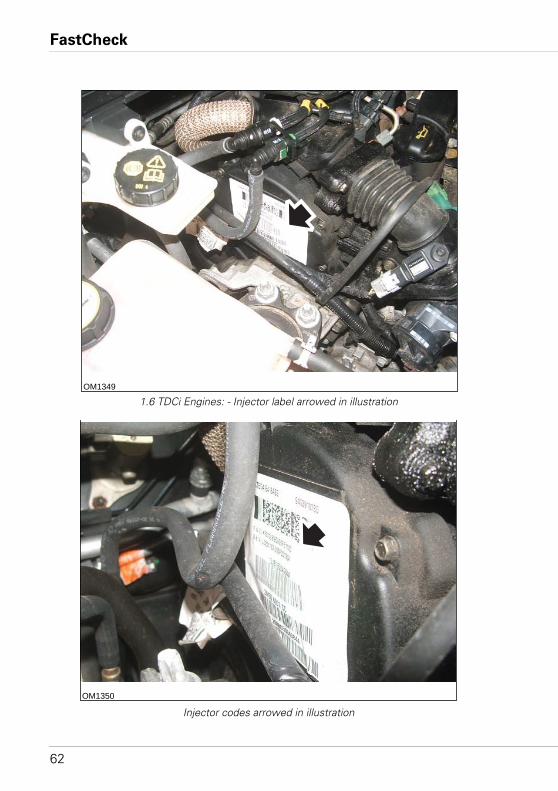
FastCheck
62
1.6 TDCi Engines: - Injector label arrowed in illustration
Injector codes arrowed in illustration
OM1349
OM1350
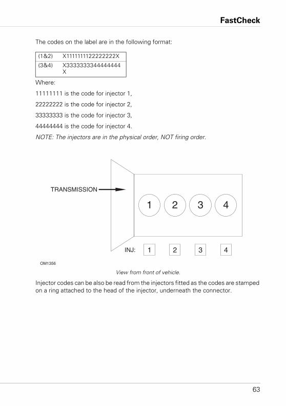
FastCheck
63
The codes on the label are in the following format:
Where:
11111111 is the code for injector 1,
22222222 is the code for injector 2,
33333333 is the code for injector 3,
44444444 is the code for injector 4.
NOTE: The injectors are in the physical order, NOT firing order.
View from front of vehicle.
Injector codes can be also be read from the injectors fitted as the codes are stamped on a ring attached to the head of the injector, underneath the connector.
(1&2) X1111111122222222X
(3&4) X3333333344444444X
OM1356
TRANSMISSION
INJ:
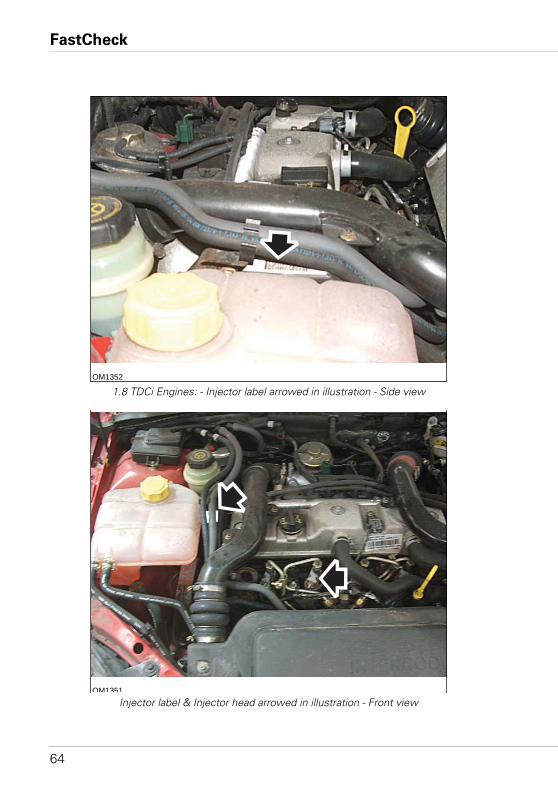
FastCheck
64
1.8 TDCi Engines: - Injector label arrowed in illustration - Side view
Injector label & Injector head arrowed in illustration - Front view
OM1352
OM1351
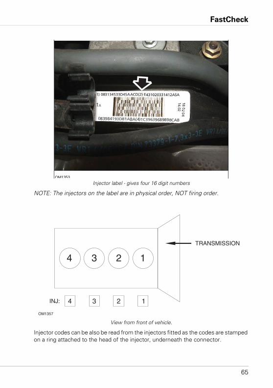
FastCheck
65
Injector label - gives four 16 digit numbers
NOTE: The injectors on the label are in physical order, NOT firing order.
View from front of vehicle.
Injector codes can be also be read from the injectors fitted as the codes are stamped on a ring attached to the head of the injector, underneath the connector.
OM1353
OM1357
TRANSMISSION
INJ:
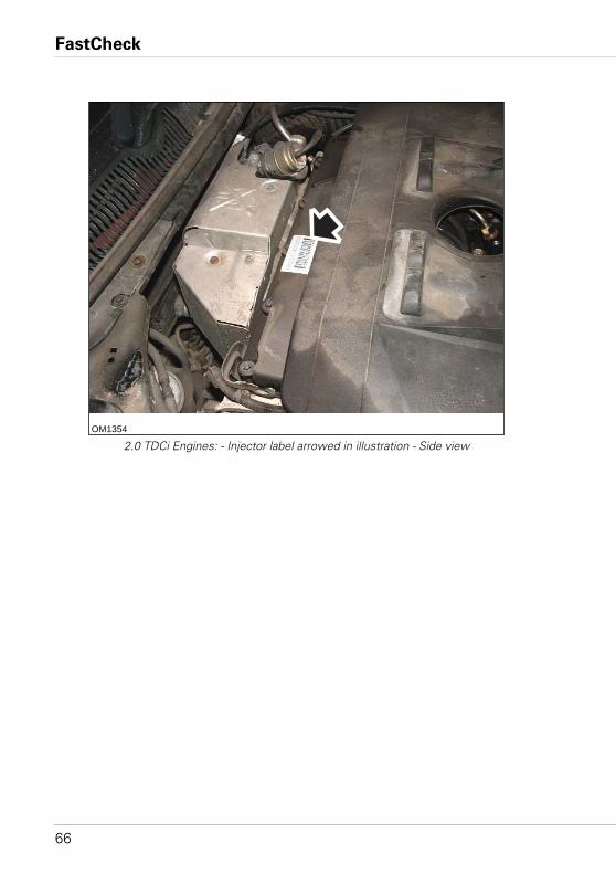
FastCheck
66
2.0 TDCi Engines: - Injector label arrowed in illustration - Side viewOM1354
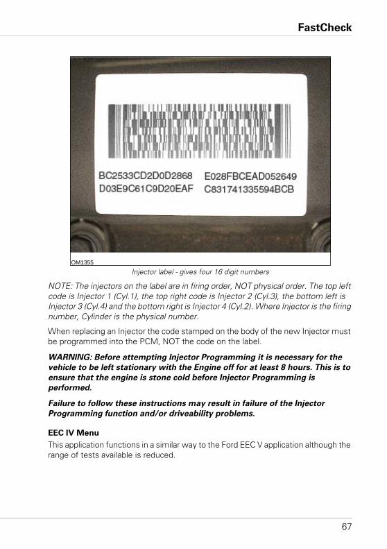
FastCheck
67
Injector label - gives four 16 digit numbers
NOTE: The injectors on the label are in firing order, NOT physical order. The top left code is Injector 1 (Cyl.1), the top right code is Injector 2 (Cyl.3), the bottom left is Injector 3 (Cyl.4) and the bottom right is Injector 4 (Cyl.2). Where Injector is the firing number, Cylinder is the physical number.
When replacing an Injector the code stamped on the body of the new Injector must be programmed into the PCM, NOT the code on the label.
WARNING: Before attempting Injector Programming it is necessary for the
vehicle to be left stationary with the Engine off for at least 8 hours. This is to
ensure that the engine is stone cold before Injector Programming is
performed.
Failure to follow these instructions may result in failure of the Injector
Programming function and/or driveability problems.
EEC IV Menu
This application functions in a similar way to the Ford EEC V application although the range of tests available is reduced.
OM1355
FastCheck
68
Live Data
Live data is read from the ECU and displayed. Pressing the button will print a snapshot of live data on the printer. Some of the parameters displayed may not be suitable to some systems. e.g. the park/neutral switch.
Cont. Codes - Continuous Codes
This displays the DTCs (fault codes) stored during a normal drive cycle.
Clear Codes
Clears the DTCs displayed in the Continuous Code test above. Some faults may only be stored in the memory under driving conditions and will not be stored after the 'Clear Continuous Codes' function. Performing the KO EO and KO ER tests will clear the memory hence 'Continuous Codes' should be read before either KO EO or KO ER is run.
KO EO Test - Key On/Engine Off Self Test
This self-test operates as in the case of EEC V.
KO ER Test - Key On/Engine Running Self Test
This test is similar to the KO EO test but with the engine running. Ensure the engine is at the correct operating temperature and follow the instructions on the display otherwise incorrect DTCs will be reported.
After the engine has been started allow the check lights to clear and normal idle to be established.
'Performing Test' will be displayed as the controller runs the test. Engine speed will rise to mark the start of the test. The operator should then promptly:
1. Turn the steering wheel full lock from left to right.• Code 521 is displayed if the action is not preformed.
2. Press and release brake pedal to operate the brake switch.• Code 536 is displayed if the action is not preformed.
3. Toggle O/D switch if fitted.• Code 653 is displayed if the action is not preformed.
4. When the engine returns to idle wait 10 - 15 seconds then blip the throttle to exceed 4000 rpm.• Code 538 is displayed if the action is not preformed.• Code 411 or 412 is displayed if the action is preformed at the wrong part
of the test.
If there is a fault present at the start then Code 998 is displayed along with the normal fault code and the self-test will not be performed.
FastCheck
69
Blink Codes Instructions
Select either 2-digit or 3-digit slow code reader from the menu according to the type listed in the application list for the vehicle under test.
While the application is reading, the tester emits sounds.
The click sound indicates that the application is running and functioning and the beep sounds when a code is being received from the system under test.
There is no live data facility available with slow code systems.
Turning the ignition off and on resets the system for the next test so the user is required to follow the scan tool instructions in order to determine when these operations should be performed.
NOTES:• Fault codes reported by this application do not necessarily indicate a faulty
component or system, Some fault codes may be for components or systems not fitted to the vehicle.
• A fault may also be reported if the test has not been performed correctly.• A fault for a component may indicate a fault wiring circuit. The wiring to the
component must be completely checked before components are changed.• All peripheral items must be switched off at the start of the test e.g. heater fans
and air conditioning.
3-Digit Systems
All the tests are routines performed by the vehicle with either the engine running or with the ignition only on. Therefore to get clear codes, actuator tests or wiggle tests, the application initiates the KO EO or KO ER tests.
Fault codes are output during the KO EO and KO ER test.
There are two types of fault output by the vehicle. The first are current faults that are present at the time of test and KAM (Keep Alive Memory) which are faults recorded in the memory and may be present or have occurred and are now absent.
A feature of these systems is that fault codes are transmitted twice, so although the repeated codes will appear on the screen, the final code listing will only display the faults once.
During the test, the scan tool application will instruct the user to perform actions. For instance, Turn the steering wheel or Press the throttle. These actions not only allow the system to test the switches but also indicate to the vehicle to progress through the test. If these actions are not followed, the test result output indicates that the test was not performed correctly. The user should make a judgement as to whether this is correct or that a switch is faulty.
FastCheck
70
KO EO Test - Key On/Engine Off Self Test
KO EO test runs the complete set of functions:
1. Read present fault codes. This function will take a while but an indication of progress should occur within one minute. If there is no response, assume communication problems and check the connection and that the ignition is turned on as and when instructed.
2. Read KAM fault codes. This operates in the same way as reading present fault codes as described above.
3. Actuator (circuit) tests. While Actuator test is displayed, pressing the throttle will cause actuators and relays to be turned on and off in line with the throttle switch. Listening and feeling the relays enables the user to determine the function of these circuits.
4. Wiggle test. This routine functions in the same way as the wiggle test listed below.
KO ER Test - Key On/Engine Running Self Test
KO ER test requires that the engine is at normal operating temperature (above 80°C). A good indication of this is when the cooling fan switches on for the first time.
The testing is performed in the same manner as the KO EO test with the exception that there is no Actuator test available. There may be more user operations to perform so it is recommended that the scan tool screen be watched carefully.
Wiggle Test
Wiggle test is used to look for open-circuit wiring faults between sensors and the engine controller. The controller responds quite slowly to this test so slow movements of the wiring should be undertaken to generate a wiggle test fault.
Practice the wiggle test by removing and replacing a connector like the throttle potentiometer and watching the scan tool display for the change of state.
Some sensors can only be detected in the KO EO condition while others only in the KO ER mode.
The application will initiate the fault reading process then when codes start, will activate the wiggle test. Wait while this occurs.
Clear Fault Codes
Do not perform this operation until after the KO EO and KO ER tests have been performed, as this function will delete any stored codes.
The application will initiate the fault reading process then when codes start, will activate the clear code routine. Wait whilst this occurs.
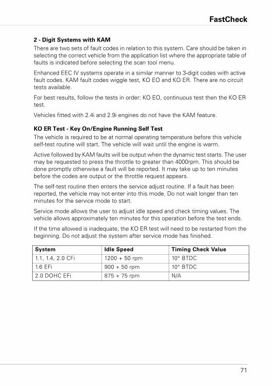
FastCheck
71
2 - Digit Systems with KAM
There are two sets of fault codes in relation to this system. Care should be taken in selecting the correct vehicle from the application list where the appropriate table of faults is indicated before selecting the scan tool menu.
Enhanced EEC IV systems operate in a similar manner to 3-digit codes with active fault codes. KAM fault codes wiggle test, KO EO and KO ER. There are no circuit tests available.
For best results, follow the tests in order: KO EO, continuous test then the KO ER test.
Vehicles fitted with 2.4i and 2.9i engines do not have the KAM feature.
KO ER Test - Key On/Engine Running Self Test
The vehicle is required to be at normal operating temperature before this vehicle self-test routine will start. The vehicle will wait until the engine is warm.
Active followed by KAM faults will be output when the dynamic test starts. The user may be requested to press the throttle to greater than 4000rpm. This should be done promptly otherwise a fault will be reported. It may take up to ten minutes before the codes are output or the throttle request appears.
The self-test routine then enters the service adjust routine. If a fault has been reported, the vehicle may not enter into this mode. Do not wait longer than ten minutes for the service mode to start.
Service mode allows the user to adjust idle speed and check timing values. The vehicle allows approximately ten minutes for this operation before the test ends.
If the time allowed is inadequate, the KO ER test will need to be restarted from the beginning. Do not adjust the system after service mode has finished.
System Idle Speed Timing Check Value
1.1, 1.4, 2.0 CFi 1200 + 50 rpm 10° BTDC
1.6 EFi 900 + 50 rpm 10° BTDC
2.0 DOHC EFi 875 + 75 rpm N/A
FastCheck
72
Clear Fault Codes
Active fault codes are cleared when the problem is repaired. KAM faults are automatically cleared as a consequence of reading the fault code. Therefore it is important that the faults are recorded during the test.
Disconnecting the vehicle battery will also erase any codes stored. This may result in surging engine speed, lumpy idle, hesitancy and poor driveability. When the battery is reconnected:• Allow engine to idle for three minutes.• Wait until the engine reaches normal operating temperature.• Raise the engine speed to 1200 rpm and hold for two minutes.• Drive the vehicle for five miles under a variety of road and traffic conditions.
2- Digit Systems Without KAM (2.8i & 2.0i) and IAW Systems
Active fault codes only are available on this system. Any faults are cleared when the ignition is switched off. Before reading fault codes, allow the vehicle some time to determine whether any faults are present for both ignition on, engine off and with engine running.
The user will be asked to crank the engine if the engine will not start. This is for the system to test the vehicle components.
EPIC
This system operates as in the case of EEC V.
GM Opel/Vauxhall
Application Menu
Select ‘GM Opel/Vauxhall’ from the Main Menu.
From the sub-menu select the required system e.g. EMS (Engine Management System) or CAN System Search.
CAN System Search
The first option in the menu is ’CAN System Search’. This option can only be used with the Multiplexer cable (YTD965) or the CAN Converter Cable (YTD960). The function is applicable to the following vehicles:
GM Opel/Vauxhall - Astra H
GM Opel/Vauxhall - Corsa D
GM Opel/Vauxhall - Signum
GM Opel/Vauxhall - Vectra C
GM Opel/Vauxhall - Zafira B
FastCheck
73
The scan tool will communicate with the vehicle’s Instrument Pack to determine the vehicle model. If the vehicle model is unknown the operator will be asked to select the vehicle model.
This function allows the Read DTCs and Clear DTCs on all Control Modules fitted to the above vehicles.
Read DTCs
The scan tool will automatically communicate with all Control Modules. A list of Control Modules found and the number of DTCs stored on each will be displayed.
The operator can then select a Control Module and view and print the DTCs stored.
Clear DTCs
The scan tool gives the option to Clear DTCs from ALL Control Modules fitted to the vehicle (Clear All DTCs), or to Clear DTCs from each individual Control Module separately (Clear DTCs by ECU).
When ‘Clear all DTCs’ is selected the scan tool will communicate with ALL Control Modules fitted to the vehicle and send a Clear DTCs command. The scan tool will then read all DTCs from all Control Modules and display a list of the results.
When ‘Clear DTCs by ECU’ is selected the scan tool will automatically communicate with all Control Modules and produce a list of Control Modules found and the number of DTCs stored.
The operator can then select a Control Module and Clear the DTCs from that Control Module. The operator can then update the list of DTCs by prompting the scan tool to re-read all DTCs or go back to the original list and select another Control Module to clear.
System Selection
Alternatively the operator can manually select individual systems from the main menu (e.g. Body Control Module or Power Steering).
Read DTCs and Clear DTCs can then be performed on the selected Control Module.
FastCheck
74
Engine Management Systems (Only)
The Multiplexer cable (YTD965) or the CAN Converter (YTD960) harness must be used for any diagnostics on the following vehicles:
GM Opel/Vauxhall - Astra H
GM Opel/Vauxhall - Corsa D
GM Opel/Vauxhall - Signum
GM Opel/Vauxhall - Vectra C
GM Opel/Vauxhall - Zafira B
For all other 16-pin vehicles any of the listed cables can be used (Multiplexer (YTD965) CAN Converter (YTD960), EOBD (YTD950) or Pin-Switchable (YTD951)).
If the vehicle under test was manufactured after 1998 the ‘Auto Search 1998>’ option should be used. This option prompts the scan tool to automatically identify the Engine Control Module.
If the vehicle under test was manufactured before 1999, or the operator knows the Engine Code of the vehicle or the name of the Engine Control Module, the ‘Engine Size/Code’ or the ‘Control Unit’ option should be used. These options should also be used in the rare cases where the Auto Search option cannot identify the Engine Control Module on post -1998 vehicles.
Hyundai
Connecting Procedure
• Connect red power lead to '+' (red) socket on the Hyundai harness (see cable kit YTD969).
• Connect black power lead to '-' (black) socket on the Hyundai harness (see cable kit YTD969).
• Clip red clamp of the power lead to the '+' (positive) terminal of the vehicle battery.
• Clip black clamp of the power lead to the '-' (negative) terminal of the vehicle battery.
• Connect the 25 way D-type connector to the scan tool.• Connect the 12 pin data link connector to the vehicle.
EMS
To diagnose EMS faults set the harness switch position to '1' (MPI).
FastCheck
75
Operations
The scan tool can read, view and clear fault codes from the various control modules.
WARNING: Disconnecting the battery may cause memory to be erased from
electronic unit (e.g. radio and clock).
Read Faults
The application will read any faults that may be stored on the vehicle control modules. During the read faults function, if the scan tool unit does not display any codes within 2 minutes, it can be assumed that there are no fault codes stored.
If there are fault codes stored on the control module, the scan tool will display to the user the number of faults found before continuing to the faults menu.
View Faults
This option will display the fault code and text describing the fault.
Clear Faults
This function will display to the user the methods of clearing fault codes. It is not possible for the scan tool to clear faults.
Land Rover
Control Module ID
Selecting this option displays the module version information.
Maintenance
Selecting 'Maintenance' allows the resetting of the adaptations to factory settings for the components listed in the menu. It is recommended that the adaptations be reset to factory settings as opposed to the `learned' settings once the components have been replaced.
Learn Security
This option allows the control module to learn a new security value input by the user.
Synchronise ECU
This option allows the user to setup a new/replacement ECU with the vehicles existing ECUs.
FastCheck
76
Mazda
Application Menu
The scan tool Mazda application can be used to retrieve diagnostic fault codes from Mazda' vehicles that use the 'flash' or 'blink' codes system.
EMS
To diagnose EMS faults, the flying lead harness (see cable kit YTD990) must be used.
WARNING: Follow instructions carefully. Incorrect connection of harness to
the vehicle may result in damage to the vehicle and/or the scan tool.
Connecting Procedure
• Connect red power lead to '+' (red) socket on the flying lead harness (see cable kit YTD990).
• Connect black power lead to '-' (black) socket on the flying lead harness (see cable kit YTD990).
• Clip red clamp of the power lead to the '+' (positive) terminal of the vehicle battery.
• Clip black clamp of the power lead to the '-' (negative) terminal of the vehicle battery.
• Connect the 25 way D-type connector to the scan tool.
Refer to the Mazda connector diagram in ‘Diagnostic connector locations’, page 130, for further information.
NOTE: This is relevant to EMS only• Connect black fly lead to diagnostic connector pin 'GND' (Ground line).• Connect blue fly lead to diagnostic connector pin 'TEN' (Code Read line).• Connect yellow wire to diagnostic connector pin 'FEN' (Code Activation line).
NOTE: Always connect ground line first
Mercedes
If the vehicle under test has both the round diagnostic connector and the J1962 (16 pin) connector, the round connector should always be used to access information via the Mercedes application and the J1962 connector should be used to access data via the EOBD application.
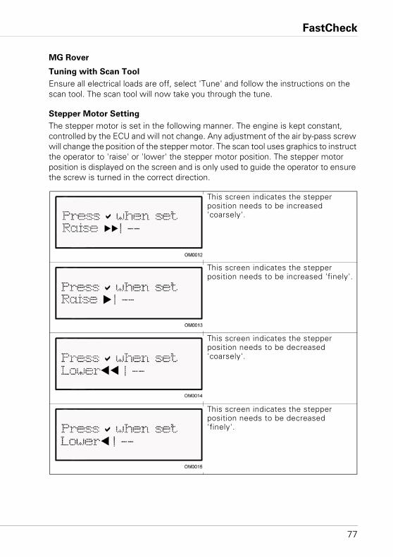
FastCheck
77
MG Rover
Tuning with Scan Tool
Ensure all electrical loads are off, select 'Tune' and follow the instructions on the scan tool. The scan tool will now take you through the tune.
Stepper Motor Setting
The stepper motor is set in the following manner. The engine is kept constant, controlled by the ECU and will not change. Any adjustment of the air by-pass screw will change the position of the stepper motor. The scan tool uses graphics to instruct the operator to 'raise' or 'lower' the stepper motor position. The stepper motor position is displayed on the screen and is only used to guide the operator to ensure the screw is turned in the correct direction.
This screen indicates the stepper position needs to be increased 'coarsely'.
This screen indicates the stepper position needs to be increased 'finely'.
This screen indicates the stepper position needs to be decreased 'coarsely'.
This screen indicates the stepper position needs to be decreased 'finely'.
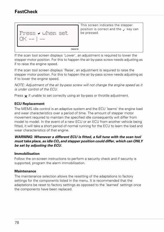
FastCheck
78
If the scan tool screen displays 'Lower', an adjustment is required to lower the stepper motor position. For this to happen the air by-pass screw needs adjusting as if to raise the engine speed.
If the scan tool screen displays 'Raise', an adjustment is required to raise the stepper motor position. For this to happen the air by-pass screw needs adjusting as if to lower the engine speed.
NOTE: Adjustment of the air by-pass screw will not change the engine speed as it is under control of the ECU.
Press if unable to set correctly using air by-pass or throttle adjustment.
ECU Replacement
The MEMS idle control is an adaptive system and the ECU `learns' the engine load and wear characteristics over a period of time. The amount of stepper motor movement required to maintain the specified idle consequently will differ from model to model. In the event of a new ECU or an ECU from another vehicle being fitted, it will take a short period of normal running for the ECU to learn the load and wear characteristics of that engine.
WARNING: Whenever a different ECU is fitted, a full tune with the scan tool
must take place, as idle CO2 and stepper position could differ, which can ONLY
be set by adjusting the ECU.
Immobilisation
Follow the on-screen instructions to perform a security check and if security is supported, program the alarm immobilisation.
Maintenance
The maintenance selection allows the resetting of the adaptations to factory settings for the components listed in the menu. It is recommended that the adaptations be reset to factory settings as opposed to the 'learned' settings once the components have been replaced.
This screen indicates the stepper position is correct and the key can be pressed.
FastCheck
79
Mitsubishi
Vehicles 1989 - 1994 MY
To display the available blink codes, the Mitsubishi harness (see cable kit YTD969) must be used with the scan tool.
Connecting Procedure
• Connect red power lead to '+' (red) socket on the Mitsubishi harness (see cable kit YTD969).
• Connect black power lead to '-' (black) socket on the Mitsubishi harness (see cable kit YTD969).
• Clip red clamp of the power lead to the '+' (positive) terminal of the vehicle battery.
• Clip black clamp of the power lead to the '-' (negative) terminal of the vehicle battery.
• Connect the 25 way D-type connector to the scan tool.• Connect the 12 pin data link connector to the vehicle.
EMS
To diagnose EMS faults set the harness switch position to '1' (MPI).
Operations
The scan tool can read, view and clear fault codes from the various control modules.
WARNING: Disconnecting the battery may cause memory to be erased from
electronic unit (e.g. radio and clock).
Read Faults
The application will read any faults that may be stored on the vehicle control modules. During the read faults function, if the scan tool does not display any codes within 2 minutes, it can be assumed that there are no fault codes stored.
If there are fault codes stored on the control module, the scan tool will display to the user the number of faults found before continuing to the faults menu.
View Faults
This option will display the fault code and text describing the fault.
Clear Faults
This function will display to the user the methods of clearing fault codes. It is not possible for the scan tool to clear faults.
FastCheck
80
1995 MY Onwards
With vehicles fitted with the J1962 OBD type diagnostic connectors, the scan tool cannot retrieve blink code faults using the standard scan tool leads.
Proton
Connecting Procedure
• Connect red power lead to '+' (red) socket on the Proton harness (see cable kit YTD969).
• Connect black power lead to '-' (black) socket on the Proton harness (see cable kit YTD969).
• Clip red clamp of the power lead to the '+' (positive) terminal of the vehicle battery.
• Clip black clamp of the power lead to the '-' (negative) terminal of the vehicle battery.
• Connect the 25 way D-type connector to the scan tool.• Connect the 12 pin data link connector to the vehicle.
EMS
To diagnose EMS faults set the harness switch position to '1' (MPi).
Renault
EMS
General
NOTE: For Renault vehicles which use the ‘Renault Card Keyless Ignition System’ and the ‘START’ button (Megane II, Scenic II etc.):
To switch the ignition on WITHOUT starting the engine:
1. Unlock the car with the remote (card).
2. Insert the card into the card reader.
3. Without pressing the brake or clutch pedal push and hold the ‘START’ button for at least 5 seconds. The dash should illuminate and the button should be released.
All diagnostics can now be carried out.
FastCheck
81
Injector Programming
The purpose of this function is to enable the technician to replace a faulty injector, or injectors, and program in the value of the new injector to the Diesel Control Unit.
It may also be used when a new Control Unit has been installed and the technician is required to program it with the values of the injectors fitted.
The function is available on most of the following Engine Management Systems:• Bosch EDC15C3, fitted to 1.9 DCi and 2.2 DCi engines. • Bosch EDC16, fitted to 1.9DCi and 2.0DCi engines.• Delphi Lucas LVCR, fitted to 1.5 DCi engines.• Delphi Lucas DDCR, fitted to 1.5 DCi engines.
Injectors are classified in the factory according to their respective flow: at idle speed, when fully charged or in the pre-injection phase.
For the Bosch systems a 6-digit alphanumeric code is engraved on the Injector indicating the classification. For the Delphi Lucas systems a 16-digit alphanumeric code is engraved on the Injector indicating the classification.
The code for each injector is stored in the memory of the ECU, enabling the ECU to control each injector taking into account the variations in their manufacture.
The Scan tool has the ability to read out the current injector codes and program in new ones.
FastCheck
82
Toyota
Pre-OBD Systems
To display all of the blink codes on pre-OBD vehicles, the flying lead harness (see cable kit YTD990) must be used with the scan tool.
WARNING: Follow instructions carefully. Incorrect connection of harness to
the vehicle may result in damage to the vehicle and/or the scan tool.
Connecting Procedure
• Connect red power lead to '+' (red) socket on the flying lead harness (see cable kit YTD990).
• Connect black power lead to '-' (black) socket on the flying lead harness (see cable kit YTD990).
• Clip red clamp of the power lead to the '+' (positive) terminal of the vehicle battery.
• Clip black clamp of the power lead to the '-' (negative) terminal of the vehicle battery.
• Connect the 25 way D-type connector to the scan tool.• Connect the fly leads to the pins of the diagnostic connector as detailed in the
following sections:
NOTE: Always connect ground line first
Refer to the Toyota connector diagram in ‘Diagnostic connector locations’, page 130, for further information.
EMS
To diagnose EMS faults:• Connect black fly lead to diagnostic connector pin 'E1' (Ground line).• Connect blue fly lead to diagnostic connector pin 'TE' or `TE1' (Code Activation
line).• Connect yellow wire to diagnostic connector pin 'W' (Code Read line).
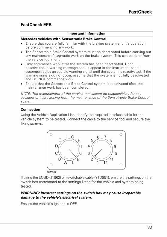
FastCheck
83
FastCheck EPB
Connection
Using the Vehicle Application List, identify the required interface cable for the vehicle system to be tested. Connect the cable to the service tool and secure the fixing screws.
If using the EOBD (J1962) pin-switchable cable (YTD951), ensure the settings on the switch box correspond to the settings listed for the vehicle and system being tested.
WARNING: Incorrect settings on the switch box may cause irreparable
damage to the vehicle's electrical system.
Ensure the vehicle's ignition is OFF.
Important information
Mercedes vehicles with Sensotronic Brake Control
• Ensure that you are fully familiar with the braking system and it's operation before commencing any work.
• The Sensotronic Brake Control system must be deactivated before carrying out any maintenance/diagnostic work on the brake system. This can be done from the service tool menu.
• Only commence work after the system has been deactivated. Upon deactivation, a warning message should appear in the instrument panel accompanied by an audible warning signal until the system is reactivated. If the warning signals do not occur, assume that the system is not fully deactivated and DO NOT commence work.
• Ensure that the Sensotronic Brake Control system is reactivated after the maintenance work has been completed.
NOTE: The manufacturer of the service tool accept no responsibility for any accident or injury arising from the maintenance of the Sensotronic Brake Control system.
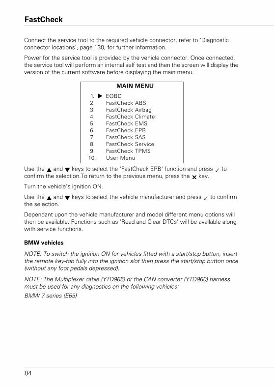
FastCheck
84
Connect the service tool to the required vehicle connector, refer to ‘Diagnostic connector locations’, page 130, for further information.
Power for the service tool is provided by the vehicle connector. Once connected, the service tool will perform an internal self test and then the screen will display the version of the current software before displaying the main menu.
Use the and keys to select the 'FastCheck EPB' function and press to confirm the selection.To return to the previous menu, press the key.
Turn the vehicle's ignition ON.
Use the and keys to select the vehicle manufacturer and press to confirm the selection.
Dependant upon the vehicle manufacturer and model different menu options will then be available. Functions such as ‘Read and Clear DTCs’ will be available along with service functions.
BMW vehicles
NOTE: To switch the ignition ON for vehicles fitted with a start/stop button, insert the remote key-fob fully into the ignition slot then press the start/stop button once (without any foot pedals depressed).
NOTE: The Multiplexer cable (YTD965) or the CAN converter (YTD960) harness must be used for any diagnostics on the following vehicles:
BMW 7 series (E65)
MAIN MENU
1. EOBD2. FastCheck ABS3. FastCheck Airbag4. FastCheck Climate5. FastCheck EMS6. FastCheck EPB7. FastCheck SAS8. FastCheck Service9. FastCheck TPMS
10. User Menu
FastCheck
85
BMW 7 Series (E65)
Parking Brake Bedding-in
If the brake shoes of the ‘Duo Servo Brake’ are replaced then the bedding process must be performed to ensure correct operation of the system. The procedure may be performed on a roller test rig or on a road test drive.
Automatic hold
The Automatic hold function applies the brakes when the vehicle is stationary and applies the brakes and parking brake when the engine is switched off. This function can be disabled / enabled.
Assembly mode
Unintentional operation of the parking brake button before the Bowden cables have engaged in the wheel carrier can lead to assembly problems. Assembly mode suppresses the activation of the parking brake.
Positioning travel check
If excessive travel has been detected then a warning is displayed and fault stored. This procedure is used to determine the cause of the problem detected by the system.
BMW X5 (E70) / X6 (E71)
Workshop mode
While in workshop mode the parking brake is placed into the opened position and the system is disabled.
Parking Brake Bedding-in
If the brake shoes of the ‘Duo Servo Brake’ are replaced then the bedding process must be performed to ensure correct operation of the system. The procedure may be performed on a roller test rig or on a road test drive.
Ford – Electronic Parking Brake (EPB) system
Two Electronic Parking Brake systems are currently supported on the service tool:
Ford Focus C-Max 2003 - present:
There are two test functions available under the calibration section of the EPB menu these are described below.
FastCheck
86
Electronic Parking Brake (EPB) calibration function test
Checks the EPB is working correctly. This test should be performed after work has been completed on the EPB or vehicle’s braking system.
The test removes any air gap from the brake pads and checks the EPB pressure.
Pre-Test conditions:
• The vehicle must be stationary• The vehicle must be on level ground• The brake fluid level is correct
The operator will be asked to perform a number of actions before applying the EPB. The service tool reads and displays the EPB pressure. With the EPB applied the EPB pressure should be approximately 1100 Newton’s.
The operator will then be asked to unlock/release the EPB. The service tool reads and displays the EPB pressure. With the EPB released the EPB pressure should be 0 Newton’s.
If either of the above tests fail (pressure reading not correct) the EPB assembly should be removed and re-assembled.
Electronic Parking Brake (EPB) emergency release calibration
Checks the EPB emergency release is working correctly. This test should be performed after work has been completed on the EPB or vehicles braking system.
Pre-test conditions:
• The vehicle must be stationary• The vehicle must be on level ground• The brake fluid level is correct
The operator will be asked to perform a number of actions before applying the EPB. The service tool reads and displays the EPB pressure. With the EPB applied the EPB pressure should be approximately 1100 Newton’s.
The operator will then be prompted to pull manually on the emergency release. The service tool reads and displays the EPB pressure. With the emergency release activated the EPB pressure should be 0 Newton’s and the vehicle should be able to move freely.
If either of the above tests fail then the EPB assembly should be inspected and repaired as described by the manufacturer’s instructions.
FastCheck
87
Ford Galaxy (2006-), Mondeo (2007-), S-Max (2006-):
There are three options in the PBM/EPB function menu which can be used to access various functions:
Service Brakes
There are three functions available under the ‘Service Brakes’ menu option:
Enter Maintenance Mode
This function is used to put the system into a state that enables work to be carried out by the technician.
The Control Module puts the calipers into a state where normal operation is inhibited and the callipers can not be closed by any means.This function must be used if replacement of the brakes, discs or brake pads is to be carried out.
Pre-Test conditions:
• The vehicle must be stationary• The vehicle must be on level ground• The vehicle must be secured with wheel locks
This function takes 30 seconds to complete.
NOTE: After this function has been performed the EPB calipers can not be closed and are inhibited until exit maintenance mode is run. Cycling the ignition, disconnecting the battery or diagnostics tester does not exit maintenance mode.
Ensure the on screen instructions on the service tool are followed precisely and in the correct order.
Exit Maintenance Mode
This function is used to put the system back into an operational state after work has been carried out by the technician. Calipers are closed to the applied position, and normal operation is available again.
Pre-Test conditions:
• The vehicle must be stationary• The vehicle must be on level ground• The vehicle must be secured with wheel locks
This function takes 35 seconds to complete.
This function also automatically performs an 'Assembly Check', which carries out internal tests on the Parking Brake system and reports the status (see below). Ensure the on screen instructions on the service tool are followed precisely and in the correct order.
FastCheck
88
Assembly Check
This function is used to check the operation of the parking brake system after any work has been completed on the system.
Pre-Test conditions:
• The vehicle must be stationary• The vehicle must be on level ground• The vehicle must be secured with wheel locks
This function takes 25 seconds to complete.
NOTE: This test is automatically run as part of the 'Exit Maintenance Mode' function. It is not necessary to perform this function if the 'Exit Maintenance Mode' function reported no problems
NOTE: This function can not be performed while the parking brake system is in maintenance mode. It should only be performed when the system is in normal operating mode.
Ensure the on screen instructions on the service tool are followed precisely and in the correct order.
Actuators
The following is available under the ‘Actuators’ menu option:
Static Apply
This function is used to test the operation of the actuators which operate the calipers. This function closes the actuators to the nominal parking brake apply position.
Pre-Test conditions:
• The vehicle must be stationary• The vehicle must be on level ground• The vehicle must be secured with wheel locks
It should be used if it is suspected that there is a fault with the Control Module, wiring, or the actuators (if the parking brake will not engage/disengage when manually operated).
NOTE: This function can not be performed while the parking brake system is in maintenance mode. It should only be performed when the system is in normal operating mode.
FastCheck
89
Configuration
There are two functions available under the ‘Configuration’ menu option:
Inclination Sensor Calibration
This function is used to reset the stored zero value of the inclination sensor. It should be used when a new Parking Brake module has been fitted or a new Inclination sensor has been fitted.
Pre-Test conditions:
• The operator must NOT be inside the vehicle• The vehicle must be stationary• The vehicle must be on level ground• Ensure the vehicle is not subject to any vibration (closing boot, bonnet, etc)• The vehicle must be secured with wheel locks
NOTE: This function cannot be performed while the parking brake system is in maintenance mode. It should be performed when the system is in normal operating mode.
Clear Stored Clutch Engagement Point
This function is used to reset the stored value of the clutch engagement point. It should be used when a new Parking Brake module has been fitted or a new clutch has been fitted. This function is only applicable to vehicles with manual transmission.
Pre-Test conditions:• The vehicle must be stationary• The vehicle must be on level ground
When this function has been performed successfully the Parking Brake module will re-learn a new clutch engagement point when the vehicle is next driven.
NOTE: This function cannot be performed while the parking brake system is in maintenance mode. It should be performed when the system is in normal operating mode.
Ensure the on screen instructions on the service tool are followed precisely and in the correct order.
Notes on Use of Functions
The four functions are designed to be used in several different situations. Here are a few situations which may occur and the correct use of the functions to rectify the situation:
FastCheck
90
Rear Brake Pad, Brake Disc or Caliper Replacement:
1. If the vehicle requires any of the above components to be replaced the 'Enter Maintenance Mode' function should be performed.
2. The system will be disabled to allow maintenance work to be carried out easily and safely.
3. After the work has been carried out the 'Exit Maintenance Mode' function should be performed.
Inclination Sensor Replacement:
1. After the new sensor has been installed perform the ‘Inclination Sensor Calibration’ function.
Clutch Replacement (manual transmission):
1. After a new clutch has been installed perform the ‘Clear Clutch Engagement Point’ function.
2. The vehicle will then learn the new clutch engagement point as the vehicle is driven.
Parking Brake Module Replacement:
1. After the Parking Brake Module has been replaced perform the ‘Inclination Sensor Calibration’ function.
2. If the vehicle has manual transmission perform the ‘Clear Clutch Engagement Point’ function.
3. The vehicle will then learn the new clutch engagement point as the vehicle is driven.
Any other EPB system component has been replaced:
1. DTCs should be read and cleared.
2. The 'Assembly Check' function should be performed to check the operation of the parking brake system.
3. If the 'Assembly Check' function fails, DTCs should be read again and the problem investigated.
The Parking Brake will not engage when manually operated via the button:
1. Ensure that the system is NOT in 'Maintenance Mode'. If it is, then perform the 'Exit Maintenance Mode' function.
2. Read DTCs, there may be a DTC stored which will indicate the area of the fault.
3. Clear DTCs, there may be an intermittent fault on the system which needs to be cleared.
4. Perform the 'Static Apply' function. This will send a command directly to the Control Module which will then close the actuators to the nominal 'engaged' position.
FastCheck
91
5. Check the switch/button.
6. Check the actuators themselves or the wiring from the ‘Control Module’ to the actuators.
Land Rover - Electronic Parking Brake (EPB) System
Discovery III (L319) (2005 - 2009), Range Rover Sport (L320) (2005 - 2009),
Range Rover (L322) (2006 - 2009):
There are four functions available under the PBM/EPB ‘Service Brakes’ menu:
Unjam Electronic Parking Brake
This procedure should be used if one of the Parking Brake cables becomes detached or breaks whilst the vehicle is being driven.
Pre-Test conditions:• The vehicle must be stationary• The engine must be running and at idle speed
After performing the procedure it is necessary for the technician to carry out checks on the condition of the rear brake shoes and drums. If both are OK the technician should then refer to the Land Rover technical information.
NOTE: Part of this procedure is to place the Parking brake into ‘Mounting Position’; in order for the checks of the rear brake shoes and drums to be carried out. When the vehicle is in the 'Mounting Position' a red flashing light will appear on the instrument cluster. This indicates that the parking brake actuator is in the 'Mounting Position'. It does not indicate a vehicle fault.
Mounting Position
The park brake must be driven to the Mounting Position if any of the following procedures are to be performed:• Parking Brake Shoes - Removal/Installation.• Parking Brake Shoe and Lining Adjustment.
This procedure must be carried out if, new parking brake shoes are fitted, new rear brake discs are fitted or if the vehicle has been mud wading (not water) for more than 50 miles. Or if one of the brake cables has broken or become detached during the vehicle being driven (in this case the Park brake is driven to the Mounting Position as part of the ‘Park Brake Unjam’ procedure above).
• Changing of Parking Brake Cables (RH and LH).
If the parking brake system has completed less than 50,000 cycles it is permissible to replace the parking brake cables. If over 50,000 cycles have been completed, then the cables can only replaced as part of the parking brake actuator and cable assembly. If a cable breaks or becomes detached whilst the vehicle is being driven, the 'parking brake unjam procedure' may be required.
FastCheck
92
• Parking Brake Actuator - Removal/InstallationThe purpose is to allow the brake cables to be connected or disconnected to the brakes.
Pre-Test conditions:
• The vehicle must be stationary.• The ignition must be on (position II).• An approved battery charger must be connected to ensure consistent power
supply.
NOTE: To remove the parking brake from Mounting Position; switch the parking brake switch on and off twice.
NOTE: When the vehicle is in the 'Mounting Position' a red flashing light will appear on the instrument cluster. This indicates that the parking brake actuator is in the 'Mounting Position'. It does not indicate a vehicle fault.
Ensure the on screen instructions on the service tool are followed precisely and in the correct order.
Latching Position
This procedure may be necessary if the Parking Brake emergency release has been activated, in order to re-latch the Parking brake.
Pre-Test conditions:
• The vehicle must be stationary.• The ignition must be on (position II).• An approved battery charger must be connected to ensure consistent power
supply.
Ensure the on screen instructions on the service tool are followed precisely and in the correct order.
FastCheck
93
Longitudinal Accelerometer Calibration
This procedure may be necessary if the Longitudinal Accelerometer has been replaced.
Pre-Test conditions:
• The ignition must be on (position II).• An approved battery charger must be connected to ensure consistent power
supply.• Ensure the vehicle is placed on a level surface and that it remains stationary
throughout the whole procedure.• Ensure the vehicle is stationary (0 km/h) on a level surface & no apply or release
command has been received.• Make sure the parking brake module is correctly secured to the vehicle and that
the parking brake is applied.
Ensure the on screen instructions on the service tool are followed precisely and in the correct order.
MANUAL FUNCTIONS
The following can be performed manually without the scan tool:
Disable Parking Brake for Rear Brake Disc Change
This procedure is necessary before carrying out work on the rear brake discs. When performed correctly the brake callipers are wound back by the control module:
Manual Routine:
• Turn the ignition key to position II.• Apply, and hold, the footbrake, • Apply, and hold, the parking brake switch to the RELEASE position.• Turn the ignition key to position 0 and remove the key.• Release the footbrake.• Release the parking brake switch.• Remove fuse number 8 from the BJB (to isolate the parking brake electrical
circuit).
This will ensure safe working conditions and eradicate the threat of the parking brake accidentally coming on while the technician is working on it.
To Re-enable Normal Operation:
• Re-install fuse number 8 into the BJB (to re-enable the parking brake electrical circuit).
FastCheck
94
Parking Brake Shoes Bedding-in Procedure
This procedure must be carried out if, new parking brake shoes are fitted, new rear brake discs are fitted or if the vehicle has been mud wading (not water) for more than 50 miles:
Manual Routine:
• Start and run the engine.• Apply the footbrake 3 times within 10 seconds and hold applied after the 3rd
application. • Apply the electronic parking brake switch 4 times, followed by 3 release
applications within 10 seconds.Once the Service Bedding-in procedure mode has been entered, the electronic parking brake linings can be bedded-in by conducting 10 repeated stops from 30 - 35 km/h (19 - 22 mph), followed by a 500 metre (547 yard) interval between each stop to allow the brakes to cool, using the electronic parking brake control switch.
• The electronic parking brake force will be increased up to the dynamic maximum so long as the switch is held in the applied position.
• If the switch is released to either the NEUTRAL or OFF positions, the electronic parking brake will be released,
• The electronic parking brake MUST be allowed to cool between applications, either by driving at 19 mph (30 km/h) for 500 metres (547 yards) or remaining stationary for 1 minute between each application.
NOTE: The electronic parking brake 'Service Bedding-in Procedure mode' will be active for the remainder of the ignition cycle, or until the vehicle speed exceeds 31 mph (50 km/h). If the procedure needs to be re-entered, the entry actions must be repeated.
Renault - handbrake
There are test functions available under the circuit tests section of the ‘Handbrake Menu’ these are described below.
Release brakes
Pre-test conditions:
• The vehicle must be stationary• The vehicle must be on level ground• The engine must not be running
At the end of the test the handbrake will be released. The ‘Apply Brakes’ function should then be performed.
FastCheck
95
Apply brakes
Pre-test conditions:
• The vehicle must be stationary• The vehicle must be on level ground• The engine must not be running
The test requests the handbrake be applied during this test.
VAG – Electro-mechanic Parking Brake (EPB) system
VW/Audi EPB system integrates two electro-mechanical actuators (right and left parking brake motors) into the rear disc brake callipers. The EPB system replaces the traditional handbrake system.
When the vehicle is stationary or when the EPB/Auto hold button is pressed the EPB control module activates the parking bake motors on the rear wheels holding the vehicle in place.
Pre-test conditions:
• The vehicle must be stationary• The vehicle must be on level ground• The brake fluid level is correct• The Parking brake is OFF
NOTE: During the process of releasing and resetting the brake pistons the ECM may store DTCs in the EPB or ABS control modules. After completing the calibration procedure the EPB and ABS DTC memory must be cleared.
EPB for Audi A4/A5/A6 & VW Passat/Tiguan
Select the required option from the ‘Maintenance’ menu either 'Replace Pads' or ‘Service Brakes’ then follow described sequence.
Brake pad replacement/service sequence
The EPB system must be released and deactivated. Ensure the ignition is ON before following the sequence described below.
NOTE: If the sequence is not performed in the correct order the braking system may not operate correctly.
Release brakes
Select the 'Release Brakes' option from the menu. The brake pistons will now be moved to their released position. Wait until the service tool displays the release brakes now complete message before continuing.
FastCheck
96
Replace/service the brake pads
The brake pads can now be replaced or serviced following the manufacturer’s instructions.
Close brakes
Select the 'Close Brakes' option from the menu. The brake pistons will now be moved to their reset position. Wait until the service tool displays the close brakes now complete message before continuing.
Calibrate brakes
Select the 'Calibrate Brakes' option from the menu. The brake pistons will now be moved in and out to calibrate their position. Wait until the service tool displays the ‘Calibrate Brakes Now Complete’ message before continuing.
EPB for Audi A8
Select the required option from the ‘Maintenance’ menu either 'Replace Pads' or 'Service Brakes' then follow the required sequence.
Brake pad replacement sequence (only)
The EPB system must be released and deactivated. Ensure the ignition is ON before following the sequence described below.
NOTE: If the sequence is not performed in the correct order the braking system may not operate correctly.
Replace pads
Select the 'Replace Pads' option from the 'Replace Pads' menu. The brake pistons will now be moved to their released position. Wait until the service tool displays the ‘Release Brakes Now Open for Pad Change’ message before continuing.
Replace the brake pads
Make a note of the new pad thickness as it is required for the next stage. The brake pads can now be replaced following the manufacturer’s instructions.
Pad thickness
The brake pad thickness must now be entered by selecting ‘Pad Thickness’ from the ‘Replace Pads’ menu. The current value is displayed on screen. Press the key until the value you wish to change is highlighted. Use the and keys to enter the new value. Values must be between 3-14mm. Repeat this sequence if necessary. When each digit is correct press the key to move to the ‘Store New Value’ screen. Pressing the key again will store the new value to the control module.
FastCheck
97
Close brakes
Select the 'Close Brakes' option from the ‘Replace Pads’ menu. The brake pistons will now be moved to their reset position. Wait until the service tool displays the ‘Close Brakes Now Complete’ message before continuing.
Calibrate brakes
Select the 'Calibrate Brakes' option from the ‘Replace Pads’ menu. The brake pistons will now be moved in and out to calibrate their position. Wait until the service tool displays the ‘Calibrate Brakes Now Complete’ message before continuing.
Brakes service sequence (only)
The EPB system must be released and deactivated. Ensure the ignition is ON before following the sequence described below.
NOTE: If the sequence is not performed in the correct order the braking system may not operate correctly.
Release brakes
Select the 'Release Brakes' option from the ‘Service Brakes’ menu. The brake pistons will now be moved to their released position. Wait until the service tool displays the ‘Release Brakes Now Complete’ message before continuing.
Service the brakes
The brakes can now be serviced following the manufacturer’s instructions.
Close brakes
Select the 'Close Brakes' option from the ‘Service Brakes’ menu. The brake pistons will now be moved to their reset position. Wait until the service tool displays the ‘Close Brakes Now Complete’ message before continuing.
Calibrate brakes
Select the 'Calibrate Brakes' option from the ‘Service Brakes’ menu. The brake pistons will now be moved in and out to calibrate their position. Wait until the service tool displays the ‘Calibrate Brakes Now Complete’ message before continuing.
FastCheck
98
Volvo - Electronic Parking Brake (EPB) System
Volvo S80 (2007 -), V70 (2008 -), XC60 (2009-), XC70 (2008 -)
There are three options in the PBM/EPB function menu which can be used to access various functions:
There are three functions available under the ‘Service Brakes’ menu option:
Enter Service Mode
This function is used to put the system into a state that enables work to be carried out by the technician. The Control Module puts the callipers into a state where normal operation is inhibited and the callipers cannot be closed by any means. This function must be used if replacement of the brakes, discs or brake pads is carried out.
Pre-Test conditions:
• The vehicle must be stationary• The vehicle must be on level ground• The vehicle must be secured with wheel locks.
This function takes 30 seconds to complete.
NOTE: After this function has been performed the EPB callipers cannot be closed and are inhibited until exit service mode is run. Cycling the ignition, disconnecting the battery or diagnostics tester does not exit maintenance mode.
Ensure the on screen instructions on the service tool are followed precisely and in the correct order.
Exit Service Mode
This function is used to put the system back into an operational state after work has been carried out by the technician. Callipers are closed to the applied position, and normal operation is available again.
Pre-Test conditions:
• The vehicle must be stationary• The vehicle must be on level ground• The vehicle must be secured with wheel locks.
This function takes 10 seconds to complete.
Ensure the on screen instructions on the service tool are followed precisely and in the correct order.
FastCheck
99
Installation Check
This function is used to check the operation of the parking brake system after any work has been completed on the system.
Pre-Test conditions:
• The vehicle must be stationary• The vehicle must be on level ground• The vehicle must be secured with wheel locks.
Three internal tests are performed, each will report the status. If any of these tests fail to perform the Read DTCs function to detect the possible fault with the system.
This function takes 25 seconds to complete.
NOTE: This function cannot be performed while the parking brake system is in service mode. It should only be performed when the system is in normal operating mode.
Ensure the on screen instructions on the service tool are followed precisely and in the correct order.
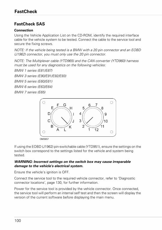
FastCheck
100
FastCheck SAS
Connection
Using the Vehicle Application List on the CD-ROM, identify the required interface cable for the vehicle system to be tested. Connect the cable to the service tool and secure the fixing screws.
NOTE: If the vehicle being tested is a BMW with a 20 pin connector and an EOBD (J1962) connector, you must only use the 20 pin connector.
NOTE: The Multiplexer cable (YTD965) and the CAN converter (YTD960) harness must be used for any diagnostics on the following vehicles:
BMW 1 series (E81/E87)
BMW 3 series (E90/E91/E92/E93)
BMW 5 series (E60/E61)
BMW 6 series (E63/E64)
BMW 7 series (E65)
If using the EOBD (J1962) pin-switchable cable (YTD951), ensure the settings on the switch box correspond to the settings listed for the vehicle and system being tested.
WARNING: Incorrect settings on the switch box may cause irreparable
damage to the vehicle's electrical system.
Ensure the vehicle's ignition is OFF.
Connect the service tool to the required vehicle connector, refer to ‘Diagnostic connector locations’, page 130, for further information.
Power for the service tool is provided by the vehicle connector. Once connected, the service tool will perform an internal self test and then the screen will display the version of the current software before displaying the main menu.
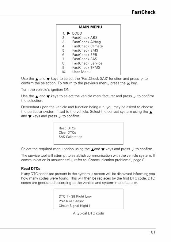
FastCheck
101
Use the and keys to select the 'FastCheck SAS' function and press to confirm the selection. To return to the previous menu, press the key.
Turn the vehicle's ignition ON.
Use the and keys to select the vehicle manufacturer and press to confirm the selection.
Dependant upon the vehicle and function being run, you may be asked to choose the particular system fitted to the vehicle. Select the correct system using the and keys and press to confirm.
Select the required menu option using the and keys and press to confirm.
The service tool will attempt to establish communication with the vehicle system. If communication is unsuccessful, refer to ‘Communication problems’, page 8.
Read DTCs
If any DTC codes are present in the system, a screen will be displayed informing you how many codes were found. This will then be replaced by the first DTC code. DTC codes are generated according to the vehicle and system manufacturer.
A typical DTC code
MAIN MENU
1. EOBD2. FastCheck ABS3. FastCheck Airbag4. FastCheck Climate5. FastCheck EMS6. FastCheck EPB7. FastCheck SAS8. FastCheck Service9. FastCheck TPMS
10. User Menu
Read DTCsClear DTCsSAS Calibration
DTC 1 - 38 Right LowPressure SensorCircuit Signal High{ }
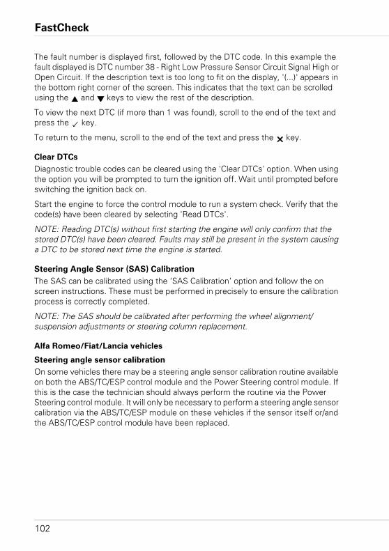
FastCheck
102
The fault number is displayed first, followed by the DTC code. In this example the fault displayed is DTC number 38 - Right Low Pressure Sensor Circuit Signal High or Open Circuit. If the description text is too long to fit on the display, '(...)' appears in the bottom right corner of the screen. This indicates that the text can be scrolled using the and keys to view the rest of the description.
To view the next DTC (if more than 1 was found), scroll to the end of the text and press the key.
To return to the menu, scroll to the end of the text and press the key.
Clear DTCs
Diagnostic trouble codes can be cleared using the 'Clear DTCs' option. When using the option you will be prompted to turn the ignition off. Wait until prompted before switching the ignition back on.
Start the engine to force the control module to run a system check. Verify that the code(s) have been cleared by selecting 'Read DTCs'.
NOTE: Reading DTC(s) without first starting the engine will only confirm that the stored DTC(s) have been cleared. Faults may still be present in the system causing a DTC to be stored next time the engine is started.
Steering Angle Sensor (SAS) Calibration
The SAS can be calibrated using the ‘SAS Calibration’ option and follow the on screen instructions. These must be performed in precisely to ensure the calibration process is correctly completed.
NOTE: The SAS should be calibrated after performing the wheel alignment/suspension adjustments or steering column replacement.
Alfa Romeo/Fiat/Lancia vehicles
Steering angle sensor calibration
On some vehicles there may be a steering angle sensor calibration routine available on both the ABS/TC/ESP control module and the Power Steering control module. If this is the case the technician should always perform the routine via the Power Steering control module. It will only be necessary to perform a steering angle sensor calibration via the ABS/TC/ESP module on these vehicles if the sensor itself or/and the ABS/TC/ESP control module have been replaced.
FastCheck
103
Longitudinal acceleration sensor calibration
This routine is necessary in the following situations:
1. The Longitudinal Acceleration Sensor has been replaced.
2. The ABS/TC/ESP control module has been replaced.
3. The ESP system is not behaving as it should. Resetting of this sensor can sometimes cure strange ESP behaviour.
BMW/MINI vehicles
NOTE: To switch the ignition ON for vehicles fitted with a start/stop button, insert the remote key-fob fully into the ignition slot then press the start/stop button once (without any foot pedals depressed).
Ford vehicles
Steering angle sensor calibration
Ka II (2008 -):
On these vehicles there may be a steering angle sensor calibration routine available on both the ABS/TC/ESP control module and the Power Steering control module. If this is the case the technician should always perform the routine via the Power Steering control module. It will only be necessary to perform a steering angle sensor calibration via the ABS/TC/ESP module on these vehicles if the sensor itself or/and the ABS/TC/ESP control module have been replaced.
Fiesta (2008 -), Fusion/B-Max (2008 -):
On these vehicles steering angle sensor calibration is performed via the Power Steering control module only.
Ford Galaxy (2006 -), Mondeo (2007 -), S-Max (2006 -), Transit (2006 -):
On these vehicles steering angle sensor calibration is performed via the ABS/TC/ESP control module only.
Longitudinal acceleration sensor calibration:
This routine is necessary in the following situations:
1. The Longitudinal Acceleration Sensor has been replaced.
2. The ABS/TC/ESP control module has been replaced.
3. The ESP system is not behaving as it should. Resetting of this sensor can sometimes cure strange ESP behaviour.
FastCheck
104
Land Rover vehicles
Longitudinal acceleration sensor calibration:
This routine is necessary in the following situations:
1. The Longitudinal Acceleration Sensor has been replaced.
2. The ABS/TC/ESP control module has been replaced.
3. The ESP system is not behaving as it should. Resetting of this sensor can sometimes cure strange ESP behaviour.
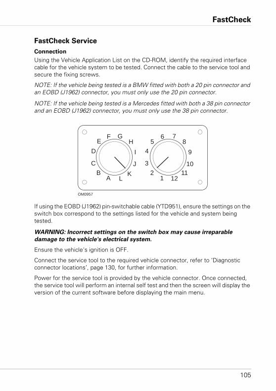
FastCheck
105
FastCheck Service
Connection
Using the Vehicle Application List on the CD-ROM, identify the required interface cable for the vehicle system to be tested. Connect the cable to the service tool and secure the fixing screws.
NOTE: If the vehicle being tested is a BMW fitted with both a 20 pin connector and an EOBD (J1962) connector, you must only use the 20 pin connector.
NOTE: If the vehicle being tested is a Mercedes fitted with both a 38 pin connector and an EOBD (J1962) connector, you must only use the 38 pin connector.
If using the EOBD (J1962) pin-switchable cable (YTD951), ensure the settings on the switch box correspond to the settings listed for the vehicle and system being tested.
WARNING: Incorrect settings on the switch box may cause irreparable
damage to the vehicle's electrical system.
Ensure the vehicle's ignition is OFF.
Connect the service tool to the required vehicle connector, refer to ‘Diagnostic connector locations’, page 130, for further information.
Power for the service tool is provided by the vehicle connector. Once connected, the service tool will perform an internal self test and then the screen will display the version of the current software before displaying the main menu.
AB
C
DE
F GH
I
JK
L 12
3
45
6 78
9
1011
12
OM0957
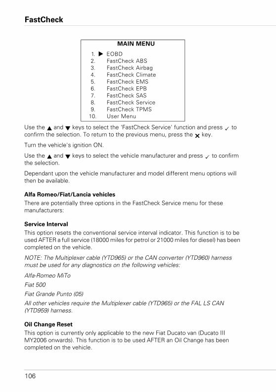
FastCheck
106
Use the and keys to select the 'FastCheck Service' function and press to confirm the selection. To return to the previous menu, press the key.
Turn the vehicle's ignition ON.
Use the and keys to select the vehicle manufacturer and press to confirm the selection.
Dependant upon the vehicle manufacturer and model different menu options will then be available.
Alfa Romeo/Fiat/Lancia vehicles
There are potentially three options in the FastCheck Service menu for these manufacturers:
Service Interval
This option resets the conventional service interval indicator. This function is to be used AFTER a full service (18000 miles for petrol or 21000 miles for diesel) has been completed on the vehicle.
NOTE: The Multiplexer cable (YTD965) or the CAN converter (YTD960) harness must be used for any diagnostics on the following vehicles:
Alfa-Romeo MiTo
Fiat 500
Fiat Grande Punto (05)
All other vehicles require the Multiplexer cable (YTD965) or the FAL LS CAN (YTD959) harness.
Oil Change Reset
This option is currently only applicable to the new Fiat Ducato van (Ducato III MY2006 onwards). This function is to be used AFTER an Oil Change has been completed on the vehicle.
MAIN MENU
1. EOBD2. FastCheck ABS3. FastCheck Airbag4. FastCheck Climate5. FastCheck EMS6. FastCheck EPB7. FastCheck SAS8. FastCheck Service9. FastCheck TPMS
10. User Menu
FastCheck
107
Oil Degradation Counter Reset
This option is necessary on vehicles which have Diesel Particulate Filters (DPF) fitted. This is NOT necessary on vehicles with petrol or LPG engines or diesel engines if DPF is not fitted. When selected the scan tool will interrogate the vehicle to determine the applicability of the function.
This function allows the resetting of the Oil Degradation Counter and viewing of the Oil Degradation parameters (number of resets, Oil Degradation Counter %, km until next reset required, odometer at last reset). The counter should only be reset AFTER the Oil has been changed. When reset the Counter will be reset to 100%, the number of resets will increase by 1.
Alfa Romeo vehicles- Mannesman Dashboard (147 and GT - UK only)
For Alfa Romeo vehicles with the Mannesman Dashboard (147 and GT) there is a problem with the Dashboard which causes the 'Number of miles to Service' value to be set to zero when a Service Reset is performed using the service tool.
When the Service Reset is performed the Dashboard stores the current mileage (or kilometre) value, read from the Odometer, in order to calculate when the next service is required.
However, when the Odometer is shown in miles the calculation for the distance to the next service fails. This results in distance to the next service being displayed as zero and the Service Reset fails to be completed.
To reset the Service Interval the following procedure must be performed:
1. Switch the Ignition ON.
2. Press the [MODE] button on the dashboard to enter the dashboard functions menu.
3. Use the [+] and [-] buttons on the dashboard to navigate to the UNITS option and press [MODE] to select.
4. Use the [MODE], [+] and [-] buttons to set the units to Kilometres. All other settings should be left unchanged.
5. Use the [+] and [-] buttons on the dashboard to navigate to the END MENU option and press [MODE] to exit the functions menu.
6. Plug the service tool into the Diagnostic Socket (using the 16-pin FAL LS CAN harness) and perform a Service Reset by selecting FastCheck Service, Alfa Romeo, Mannesman then Service Reset.
7. Disconnect the service tool, leaving the ignition ON.
8. Press the [MODE] button on the dashboard to enter the dashboard functions menu.
9. Use the [+] and [-] buttons on the dashboard to navigate to the UNITS option and press [MODE] to select.
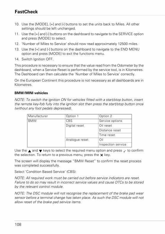
FastCheck
108
10. Use the [MODE], [+] and [-] buttons to set the units back to Miles. All other settings should be left unchanged.
11. Use the [+] and [-] buttons on the dashboard to navigate to the SERVICE option and press [MODE] to select.
12. 'Number of Miles to Service' should now read approximately 12500 miles.
13. Use the [+] and [-] buttons on the dashboard to navigate to the END MENU option and press [MODE] to exit the functions menu.
14. Switch Ignition OFF.
This procedure is necessary to ensure that the value read from the Odometer by the dashboard, when a Service Reset is performed by the service tool, is in Kilometres. The Dashboard can then calculate the 'Number of Miles to Service' correctly.
On the European Continent this procedure is not necessary as all dashboards are in Kilometres.
BMW/MINI vehicles
NOTE: To switch the ignition ON for vehicles fitted with a start/stop button, insert the remote key-fob fully into the ignition slot then press the start/stop button once (without any foot pedals depressed).
Use the and keys to select the required menu option and press to confirm the selection. To return to a previous menu, press the key.
The screen will display the message “BMW Reset” to confirm the reset process was completed successfully.
Select ‘Condition Based Service’ (CBS):
NOTE: All required work must be carried out before service indicators are reset. Failure to do so may result in incorrect service values and cause DTCs to be stored by the relevant control module.
NOTE: The DSC module will not recognise the replacement of the brake pad wear sensor before a terminal change has taken place. As such the DSC module will not allow reset of the brake pad service items.
Manufacturer Option 1 Option 2BMW CBS Service options
Digital reset Oil resetDistance resetTime reset
Analogue reset OilInspection service
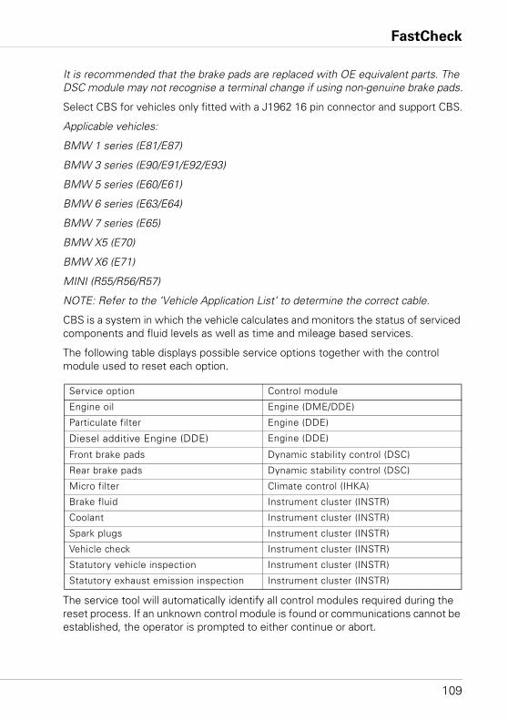
FastCheck
109
It is recommended that the brake pads are replaced with OE equivalent parts. The DSC module may not recognise a terminal change if using non-genuine brake pads.
Select CBS for vehicles only fitted with a J1962 16 pin connector and support CBS.
Applicable vehicles:
BMW 1 series (E81/E87)
BMW 3 series (E90/E91/E92/E93)
BMW 5 series (E60/E61)
BMW 6 series (E63/E64)
BMW 7 series (E65)
BMW X5 (E70)
BMW X6 (E71)
MINI (R55/R56/R57)
NOTE: Refer to the ‘Vehicle Application List’ to determine the correct cable.
CBS is a system in which the vehicle calculates and monitors the status of serviced components and fluid levels as well as time and mileage based services.
The following table displays possible service options together with the control module used to reset each option.
The service tool will automatically identify all control modules required during the reset process. If an unknown control module is found or communications cannot be established, the operator is prompted to either continue or abort.
Service option Control module
Engine oil Engine (DME/DDE)
Particulate filter Engine (DDE)
Diesel additive Engine (DDE) Engine (DDE)
Front brake pads Dynamic stability control (DSC)
Rear brake pads Dynamic stability control (DSC)
Micro filter Climate control (IHKA)
Brake fluid Instrument cluster (INSTR)
Coolant Instrument cluster (INSTR)
Spark plugs Instrument cluster (INSTR)
Vehicle check Instrument cluster (INSTR)
Statutory vehicle inspection Instrument cluster (INSTR)
Statutory exhaust emission inspection Instrument cluster (INSTR)
FastCheck
110
NOTE: If the process is continued service options applicable to the unknown control module will not be available (see service option table).
The current date and time information will be displayed by the service tool. Press the key if the information is correct and continue or press key to correct the information.
NOTE: If date and time used during the reset process is incorrect, this will result in incorrect service intervals.
To change the date and time:
Use the and keys to change the value of the selected information indicated by '/ \'.
Use the key to change the selected date/time field.
Use the key to complete the information entry.
The screen will display a final confirmation of the new data entered. Press the key to program the new information to the vehicle.
Pressing the key at any point during the date and time change to will return to the initial date and time confirmation screen. No information will have been changed.
The service options available on the vehicle are displayed as a list. Each option is displayed with the service data:
The percentage reset value.
The estimated distance to, or the next service date.
The service counter.
NOTE: The vehicle inspection and exhaust emission inspection only display the date of the next service.
The service option list is displayed in priority order, with the most urgent first.
To reset an option scroll to the required option using the and keys. The current option will be indicated by the . Press the key to confirm the selection.
Two possible options may be displayed on the lower half of the display:-
Reset option
Correct option
Use the and keys to select the required menu option
Use the key to confirm the selection.
Use the key to cancel the selection and return to the service option list.
FastCheck
111
Reset option:
The ‘Reset’ option is used to set the selected service option’s reset value to 100%. The estimated distance or date of next service and the service counter are updated.
The vehicle inspection and exhaust emission inspection service options are statutory inspections that store the date of the next inspection.
Upon selecting either of these options the service tool will display the screen to change the next service date.
Use the and keys to change the value of the selected information indicated by '>' or '<'.
Use the key to change the selected field.
Use the key to complete and store the information.
Use the key to cancel the reset and return to the service option list.
Correct Option:
The ‘Correct’ option is used to correct a service option which has been reset in error.
NOTE: Reset correction is only available for service options with service counter not zero, and is not available for vehicle and exhaust emission inspections. The original service option values are lost during reset.
Use the and keys to change the reset value.
Use the key to complete the information entry.
A final confirmation of the new data entered is displayed. Press the key to store the new information. To cancel the correction and return to the service option list press the key.
NOTE: The maximum reset value will be the current value of the selected service option. The service counter will be decremented by 1.
Digital Reset:
Select ‘Digital Reset’ for vehicles only fitted with a J1962 16 pin connector that do not support Condition Based Service (CBS).
The service tool will display a message to confirm the reset process was successful.
Applicable vehicles:
BMW 3 Series (E46)
BMW 5 Series (E39)
BMW 7 Series (E38)
BMW X3 (E83)
FastCheck
112
BMW X5 (E53)
BMW Z4 (E85)
NOTE: A manual procedure for service reset is possible for some Digital Reset applicable vehicles. Refer to Manual Service Reset section for instructions.
Analogue reset:
Select ‘Analogue Reset’ for vehicles fitted with a 20 pin round diagnostic connector within the engine bay.
The service tool will display the message ‘Reset Complete’ to confirm the reset process was completed.
NOTE: The service tool indicates the completion of the process only. Visual confirmation via the Service Interval Indicator (SIA) located on the vehicle’s dash panel is required.
Annual distance:
The average annual distance travelled is required for the calculation of various Condition Based Service (CBS) functions.
The annual distance is based on the distance travelled after approximately six to eight weeks from being reset. It is advised to reset the annual distance after any changes in the driving pattern of the vehicle.
NOTE: Incorrect annual distance will affect the CBS intervals.
The value will be set to a default (approximately 30,000 km / 18,640 miles) until the new value has been calculated.
Applicable vehicles:
BMW 1 series (E81/E87)
BMW 3 series (E90/E91/E92/E93)
BMW 5 series (E60/E61)
BMW 6 series (E63/E64)
BMW 7 series (E65)
BMW X5 (E70)
BMW X6 (E71)
NOTE: The Multiplexer cable (YTD965) or the CAN converter (YTD960) harness must be used.
FastCheck
113
Battery change:
After fitting a new battery, the battery change function should be run. The battery change function registers the replacement of a battery with the power management system. Failure to do so may cause the power management system to operate incorrectly.
The battery change function determines the required battery capacity and type from the Car Access System (CAS) module. The replacement battery must be same capacity and type as displayed.
NOTE: Certain vehicles require the use of an Absorbent Glass Mat (AGM) battery.
Applicable vehicles:
BMW 1 series (E81/E87)
BMW 3 series (E90/E91/E92/E93)
BMW 5 series (E60/E61)
BMW 6 series (E63/E64)
BMW 7 series (E65)
BMW X5 (E70)
BMW X6 (E71)
NOTE: The Multiplexer cable (YTD965) or the CAN converter (YTD960) harness must be used.
Ford vehicles
Oil Degradation Counter Reset
This option is necessary on vehicles which have Diesel Particulate Filters (DPF) fitted. This is not necessary on vehicles with petrol or LPG engines or diesel engines if DPF is not fitted. The counter should only be reset AFTER the oil has been changed.
GM vehicles
Service interval reset
CAN vehicles - (Astra-H, Corsa-D, Signum, Vectra-C and Zafira-B)
For these vehicles the Multiplexer cable (YTD965) or the CAN converter cable (YTD960) must be used for Service Interval reset.
This function should be used after a vehicle has been serviced.
The vehicle is programmed with the number of miles and days until the next service and the Service indicator light is turned off.
FastCheck
114
The Service indicator will come on again when either the number of programmed miles is reached or the number of programmed days is reached, whichever occurs first.
The reset is started by selecting the 'Service' option.
To return to a previous menu, press the key.
The operator must then select the 'CAN Converter cable'.
The service tool will communicate with the Instrument pack to determine the vehicle model. If the vehicle model is unknown the operator must manually select the vehicle.
NOTE: Vehicle must NOT be moving during this procedure and all doors must be closed. The service tool will check the vehicle speed to ensure that the vehicle is not moving before starting the procedure.
Security key
To perform the reset the operator must enter a 4-digit security key into the service tool. This code will be programmed into the vehicle to allow a Reset to be performed.
The 4-digit security key is found in the owner’s handbook on a card with the other important codes and numbers for the vehicle (such as the VIN number and Radio code etc.).
Corsa D
The number of miles until the next service can be selected by the user, 9000 miles or 18000 miles can be selected. The number of days until the next service is always set at 364 days (1 year).
Astra-H / Zafira-B
The number of miles until the next service and number of days until the next service are calculated by the service tool depending on the operators selections of the following:
1. Country - The miles and days until next service are set to values pre-determined by GM, depending on the Country the vehicle is being used in.
The operator must first select the ‘CAN Converter cable’ if requested.
For core European Countries (UK, Ireland, France, Belgium, Germany, Spain, Italy, Portugal, Holland, Austria etc.) select 'Other European Countries'.
2. ECO service, ECO service flex - For most core European countries the Operator can set the vehicle to either 'ECO Service' (the standard GM service plan which used standard GM values for miles and days until next service) or 'ECO Service Flex' (the values for miles and days until next service are
FastCheck
115
dynamically set by the vehicle’s onboard computers, which monitor how the vehicle is being driven and set the Service Intervals accordingly).
For ECO Service Flex Petrol vehicles the service tool will program the vehicle with the maximum number of miles allowed by the Flex system (22000 miles) and the maximum number of days allowed (728, or 2 years).
For ECO Service Flex Diesel vehicles the service tool will program the vehicle with the maximum number of miles allowed by the Flex system (31000 miles) and the maximum number of days allowed (728, or 2 years).
These are default values which ensure that the Service Indicator will come on in either 22000 or 31000 miles or 2 years, whichever occurs first, if the ECO Service Flex system fails for any reason.
Vectra-C / Signum
Only a straight reset is available on these vehicles. The programmed Service Interval values of miles and days until the next service cannot be altered.
NOTE: The engine oil used on these vehicles is 'Long-life Oil'. When the engine oil is changed the technician must use the 'Long-life Oil' reset option on the service tool (see below) to reset the Engine Control Module. The technician must then select 'Service' again to restart the Service Interval Reset.
CAUTION: It is important to depress, and release, the brake pedal when prompted by the service tool during the Reset procedure. If this is not done correctly the Reset will not be successful.
Pre-CAN vehicles
The Multiplexer cable (YTD965) or the EOBD (J1962) pin-switchable cable (YTD951) must be used for pre-CAN vehicles, with switch position J2.
This function should be used after a vehicle has been serviced.
The vehicle is programmed with the number of miles and days (whichever one occurs first) until the next service. Completing this step turns the Service Indicator light OFF.
The reset is started by selecting the 'Service' option.
To return to a previous menu, press the key.
The operator must then select the 'Switchable' cable.
Please ensure that the vehicle is stationary and check that all the vehicle's doors are closed.
Press on the service tool to reset the Service Interval.
If successful the service tool will display 'Service Reset Passed'.
FastCheck
116
Long-Life oil reset
CAN Vehicles - (Vectra-C and Signum)
For these vehicles the Multiplexer cable (YTD965) or the EOBD (J1962) cable (YTD950) or the CAN converter cable (YTD960) can be used for Long-Life Oil Reset.
NOTE: The engine must NOT be running when performing this procedure.
This function must be used when an engine oil change has been performed on the vehicle.
The Long-Life Oil Reset is started by selecting the 'Long-Life Oil' option.
The Technician must then select the cable to be used.
The service tool will check the Engine Control Module to ensure that the function is supported for the current engine. This function is not supported and not necessary on Astra-H, Corsa-D or Zafira-B.
The service tool will check the engine speed to ensure that the engine is not running then read the current value of 'Remaining Oil Life' from the Engine Control Module and display. If the value is less than 15% the Oil must be changed and a reset performed.
The service tool will then perform the Reset. The 'Remaining Oil Life' parameter will be read from the Engine Control Module and displayed again. It will read 100% if the reset has been successful.
Land Rover vehicles
There are two options available for Land Rover.
Service Interval Reset
This option resets the conventional service interval indicator. This function is to be used AFTER a full service has been completed on the vehicle.
Oil Degradation Counter Reset
This option is necessary on vehicles which have Diesel Particulate Filters (DPF) fitted. This is not necessary on vehicles with petrol or LPG engines or diesel engines if DPF is not fitted. The counter should only be reset AFTER the oil has been changed.
FastCheck
117
Mercedes vehicles
There are two different types of servicing for Mercedes: Assyst Plus and Flexible Service System. The service type will automatically be determined from the vehicle.
Assyst Plus:
NOTE: Any DTCs (Diagnostic trouble codes) present on the Assyst Plus control module may lead to incorrect servicing information and services to be preformed incorrectly. Different variants of Assyst Plus have different service functions available.
Assyst Plus service functions
• Reset indicator• Additional work• Service status• Service history• Undo reset• Undo additional• Read DTCs• Clear DTCs
Reset Indicator
This function is used to reset the overall maintenance of the vehicle. The current service status information will be displayed.
To abort the reset, press the key. Confirmation of the service being aborted will be displayed, press any key at this point to return to the ‘Assyst Plus’ menu. To proceed with the reset press .
The oil quality must be selected before the reset can be completed. To abort the reset, press the key. Confirmation the reset has aborted will be displayed, press any key to return to the ‘Assyst Plus’ menu. To select the oil quality used for the service from the menu use the and keys and press to confirm the selection.
The result of the reset will be displayed, press any key to return to the ‘Assyst Plus’ menu.
Additional Work
This function is used to record additional work carried out during the latest service in the vehicle’s service memory.
The function will display a menu of all available additional work options applicable for the vehicle.
Press the and keys to scroll through the available list.
FastCheck
118
Press the key to select/deselect an item. Multiple items can be selected and any items selected are highlighted by .
Press the key to abort and return to the ‘Assyst Plus’ menu. Press to add these selected options to the last service memory. The result of the reset will be displayed, press any key to return to the ‘Assyst Plus’ menu.
Service Status
This function displays the current service status information.
Use the and keys to scroll through the status information. Press the key to exit and return to the ‘Assyst Plus’ menu.
NOTE: It can take some time for the control unit to update the service status information after a change in state (e.g. Resetting the service indicator).
Service History
This function allows the operator to review the entries held within the service memory. The function will display the number of service entries currently stored within the service memory.
Press the key to return to the ‘Assyst Plus’ menu. Select the desired entry using the and keys and press to confirm the selection.
Press the key to return to the ‘Assyst Plus’ menu. Press and keys to scroll through the service information stored in memory.
Undo Reset
This function cancels the latest service stored in the service history (i.e. the last performed service).
NOTE: A warning will be displayed before the cancel process is performed. This option is only intended for resetting a service that has accidentally been reset.
Press to return to the ‘Assyst Plus’ menu. Press to cancel the last service. Confirmation of the cancellation will be displayed. Press any key at this point to return to the ‘Assyst Plus’ menu.
NOTE: Services which have been cancelled remain in the service history. The entry will be marked as irrelevant and the data held within will be reset. The Undo Reset is only possible if there is an existing service held within the service memory.
Undo Additional
This function cancels any additional work records stored in the latest service history.
NOTE: A warning will be displayed before the undo process is performed. This option is only intended for resetting an additional service option that has accidentally been reset.
FastCheck
119
A menu of all the additional work available from the vehicle’s latest service is displayed.
Press and keys to scroll through the available list.
Press the key to select/deselect an item. Multiple items can be selected and any items selected are highlighted by .
Press to return to the ‘Assyst Plus’ menu. Press to remove the selected options from the service memory. The result of the undo will be displayed, press any key to return to the ‘Assyst Plus’ menu.
NOTE: Undo is only possible if there is an existing service held within the service memory and the selected service options are applicable to the latest service.
Flexible Service System:
Select ‘Service Reset’ and press to confirm the selection. To return to a previous menu, press the key.
When prompted to, check that all the vehicle's doors are closed, then press any button on the service tool to have the oil or service light reset.
WARNING: Be sure to close all the vehicle's doors before sending the reset
command. Not doing so can result in permanent damage to the vehicle's
instrument panel.
You will receive the message "Mercedes Reset" to confirm the reset process was completed successfully.
MG Rover vehicles
Scroll through the list of available vehicle models and press to confirm the selection. To return to a previous menu, press the key.
When prompted to, check that all the vehicle's doors are closed, then press any button on the service tool to have the oil or service light reset.
You will receive the message "MG Rover Reset" to confirm the reset process was completed successfully.
Saab vehicles
Select 'Interval and Oil' and press to confirm the selection. To return to a previous menu, press the key.
You will receive the message "Saab Reset" to confirm the reset process was completed successfully.
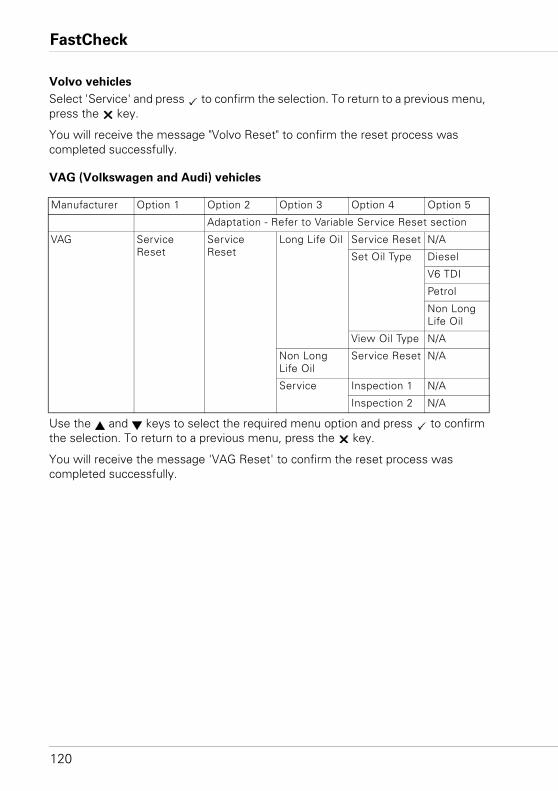
FastCheck
120
Volvo vehicles
Select 'Service' and press to confirm the selection. To return to a previous menu, press the key.
You will receive the message "Volvo Reset" to confirm the reset process was completed successfully.
VAG (Volkswagen and Audi) vehicles
Use the and keys to select the required menu option and press to confirm the selection. To return to a previous menu, press the key.
You will receive the message 'VAG Reset' to confirm the reset process was completed successfully.
Manufacturer Option 1 Option 2 Option 3 Option 4 Option 5
Adaptation - Refer to Variable Service Reset section
VAG Service Reset
Service Reset
Long Life Oil Service Reset N/A
Set Oil Type Diesel
V6 TDI
Petrol
Non Long Life Oil
View Oil Type N/A
Non Long Life Oil
Service Reset N/A
Service Inspection 1 N/A
Inspection 2 N/A
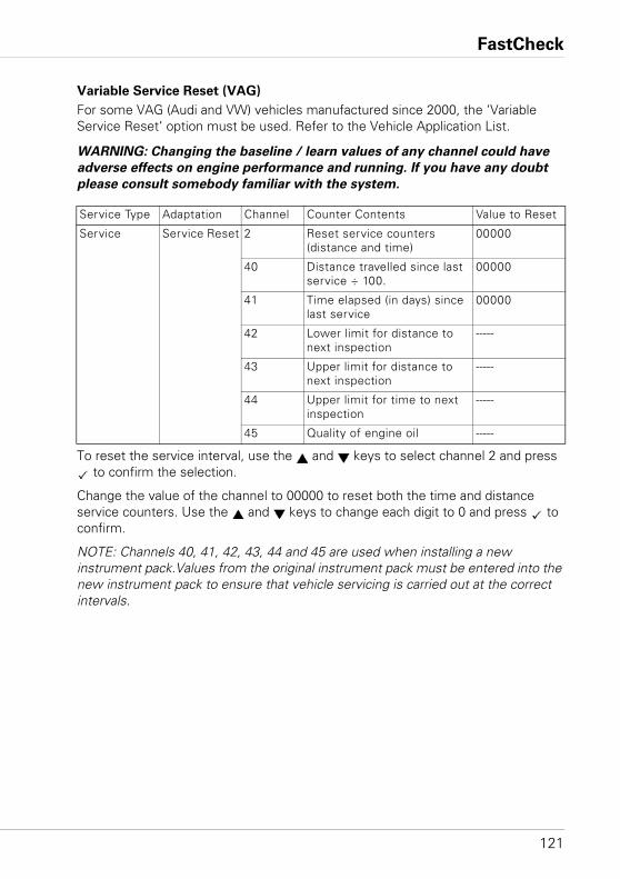
FastCheck
121
Variable Service Reset (VAG)
For some VAG (Audi and VW) vehicles manufactured since 2000, the ‘Variable Service Reset’ option must be used. Refer to the Vehicle Application List.
WARNING: Changing the baseline / learn values of any channel could have
adverse effects on engine performance and running. If you have any doubt
please consult somebody familiar with the system.
To reset the service interval, use the and keys to select channel 2 and press to confirm the selection.
Change the value of the channel to 00000 to reset both the time and distance service counters. Use the and keys to change each digit to 0 and press to confirm.
NOTE: Channels 40, 41, 42, 43, 44 and 45 are used when installing a new instrument pack.Values from the original instrument pack must be entered into the new instrument pack to ensure that vehicle servicing is carried out at the correct intervals.
Service Type Adaptation Channel Counter Contents Value to Reset
Service Service Reset 2 Reset service counters (distance and time)
00000
40 Distance travelled since last service ÷ 100.
00000
41 Time elapsed (in days) since last service
00000
42 Lower limit for distance to next inspection
-----
43 Upper limit for distance to next inspection
-----
44 Upper limit for time to next inspection
-----
45 Quality of engine oil -----
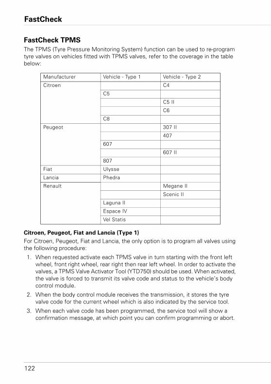
FastCheck
122
FastCheck TPMS
The TPMS (Tyre Pressure Monitoring System) function can be used to re-program tyre valves on vehicles fitted with TPMS valves, refer to the coverage in the table below:
Citroen, Peugeot, Fiat and Lancia (Type 1)
For Citroen, Peugeot, Fiat and Lancia, the only option is to program all valves using the following procedure:
1. When requested activate each TPMS valve in turn starting with the front left wheel, front right wheel, rear right then rear left wheel. In order to activate the valves, a TPMS Valve Activator Tool (YTD750) should be used. When activated, the valve is forced to transmit its valve code and status to the vehicle’s body control module.
2. When the body control module receives the transmission, it stores the tyre valve code for the current wheel which is also indicated by the service tool.
3. When each valve code has been programmed, the service tool will show a confirmation message, at which point you can confirm programming or abort.
Manufacturer Vehicle - Type 1 Vehicle - Type 2
Citroen C4
C5
C5 II
C6
C8
Peugeot 307 II
407
607
607 II
807
Fiat Ulysse
Lancia Phedra
Renault Megane II
Scenic II
Laguna II
Espace IV
Vel Statis
FastCheck
123
Citroen, Peugeot, Fiat and Lancia (Type 2)
With these vehicles all tyres need to be inflated to 3.7 bar for programming to be successful. In order for the valves to transmit their codes a TPMS Valve Activator Tool (YTD750) should be used.
Follow the on screen instructions which indicate the order the wheels are to be programmed in. The spare wheel is included along with the other wheels, but if this option is not supported by the vehicle, a message will appear after a few seconds to indicate this.
NOTE: Remember to reset the correct tyre pressures when finished.
Renault
General
NOTE: For Renault vehicles which use the ‘Renault Card Keyless Ignition System’ and the ‘START’ button (Megane II, Scenic II etc.):
To switch the ignition on WITHOUT starting the engine:
1. Unlock the car with the remote (card).
2. Insert the card into the card reader.
3. Without pressing the brake or clutch pedal push and hold the ‘START’ button for at least 5 seconds. The dash should illuminate and the button should be released.
All diagnostics can now be carried out.
TPMS is the Tyre Pressure Monitoring System.
Each valve sensor has a unique code and is matched to a particular wheel. This is programmed into the UCH control module. This enables a faulty wheel to be identified (given that the receiver can identify which wheel is transmitting). The sensor emits an RF (Radio Frequency) signal containing the valve code, status and tyre pressure. If wheels are to be swapped around then reprogramming will need to be carried out to identify the new position of the wheel.
Each valve sensor has a coloured ring attached to the valve nut, each colour corresponds to a particular wheel position:
Front Left: Green
Front Right: Yellow
Rear Left: Red
Rear Right: Black
It is recommended that if tyres are moved around that the coloured rings are replaced in the correct wheel position.
FastCheck
124
Each valve sensor will emit a signal every hour if stationary, and every 15 minutes if a leak is present. If moving it will emit a signal every minute if no leak is present, and every 10 seconds if a leak is present.
NOTE: In the live data the tyre pressures will display a default value of 3.5 bar until the valves have been forced to transmit.
Renault (Type 1)
This feature allows the user to read and clear faults, view live data, test the TPMS display lights and reprogram the unit via the Command Menu.
The Command Menu features are:
1. Program tyre valves - This allows the user to program 1 valve or 4 valves by
a. Manually entering the valve code from the keypad. The code is written on a label if the sensor is new, or if the sensor is used then remove the tyre and read the code on the sensor
b. Automatically forcing the valve to emit the code by using a TPMS Valve Activator Tool (YTD750), or deflating the tyre pressure by at least 1 bar, or rotating the wheel by more than 20 km/h. When deflating the tyre the valve will not transmit until 15 minutes has elapsed.
NOTE: If fault code 0007 is present, automatic coding will not be possible. When using the TPMS Valve Activator Tool (YTD750) it should be placed resting on the tyre under the appropriate valve. When the sensor has been excited and the transmitted code has been received the service tool will indicate a successful read. The option is then given to program the new code.
2. Select the winter tyre option - This is used during the winter in some countries where the weather conditions require winter tyres.
3. Select the summer tyre option - This is used as default or during the summer when winter tyres are changed.
4. Set control module with TPMS option - Programs the control module with the TPMS option.
5. Set control module without TPMS option - Disables the TPMS option.
6. Set tyre pressure limits - Enables the setting of maximum and minimum tyre pressure limits.
7. Change trigger limit.
8. Drive the actuator - Tests the TPMS display lights.
FastCheck
125
Renault (Type 2)
With these vehicles all tyres need to be inflated to 3.7 bar for programming to be successful. In order for the valves to transmit their codes a TPMS Valve Activator Tool (YTD750) should be used.
An option is given as to select the current tyre set (Summer/Winter). Follow the on screen instructions which indicate the order the wheels are to be programmed in. After operating the TPMS Valve Activator Tool (YTD750) alongside the requested wheel, if successful a message will be displayed on the screen indicating that the valve code has been detected and displaying the valve code. After all 4 wheel codes have been successfully detected then an option is given to program the codes.
NOTE: Remember to reset the correct tyre pressures when finished.
TPMS Trouble shooting
If a valve appears to not respond when stimulated with a TPMS Valve Activator Tool (YTD750), check the following:• The tyre valve is a TPMS valve.• The TPMS activator tool is not pointing directly at the valve stem. The valve stem
is metal and will prevent a good RF signal. On low profile tyres, the area for the RF to penetrate the tyre sidewall is small, carefully aim the TPMS Valve Activator Tool (YTD750) half-way between the tyre rim and the tread.
• Check the batteries are not low in the TPMS Valve Activator Tool (YTD750) and the TPMS valve.
• If there is no response from the valve after the checks have been made then it could be that the TPMS valve itself is faulty.
Manual TPMS Process
BMW
Run-flat Reset (RPA – Tyre Deflation Detection)
The run-flat system monitors the pressure in the four mounted tyres while the vehicle is being driven.
The system will provide an alert whenever the inflation pressure in a tyre drops significantly in relation to the pressure of another tyre.
The following BMW vehicles have the RPA system fitted:
BMW 3 Series (E90/E91/E92/E93)
BMW 5 Series (E60/E61)
BMW 7 Series (E65/E66/E67/E68)
BMW X3 (E83)
BMW X5 (E53)
FastCheck
126
It is necessary to initiate the RPA reset process IMMEDIATELY after every tyre pressure correction, after a tyre or wheel change or after a trailer has been attached or detached. The reset MUST be started before driving the vehicle for the first time after one of the above events.
When a reset is required (due to a pressure change in one of the tyres) the vehicle will inform the driver by turning on the RPA Warning Lamp, which will glow red, and sounding an acoustic signal.
When the RPA Warning Lamp is on but the colour is yellow this indicates that the RPA system has failed or is malfunctioning. In this case the system must be diagnosed using the scan function of the service tool.
The RPA reset process can be started in two different ways depending on the model.
For vehicles with an iDrive (BMW 5 Series (E60/E61), BMW 7 Series (E65/E66/
E67/E68)):
• On iDrive open the menu.• Select ‘Vehicle Settings’.• Select ‘FTM’.• Start the Engine but do NOT start driving.• Select ‘Set Tyre Pressure’.• Select ‘Yes’.• Start to drive the vehicle, the message ‘initialising’ should be displayed on the
iDrive screen.• The Reset process will terminate shortly after the vehicle beings to move. The
message ‘Status: Active’ should be displayed on the iDrive screen when the Reset process has terminated correctly.
• If the vehicle is stopped while the reset is occurring the reset will be interrupted and will be resumed when the vehicle is driven again.
For BMW 3 Series (E90/E91/E92/E93):
• Start the engine but do NOT start driving.• Use the menu control button on the indicator stalk to move up or down until the
‘RESET’ menu item appears. • Press the select button on the end of the indicator stalk to confirm your choice
of the Run Flat Indicator reset option.• Hold the button down for approximately 5 seconds until the ‘RESET?’ symbol is
shown.
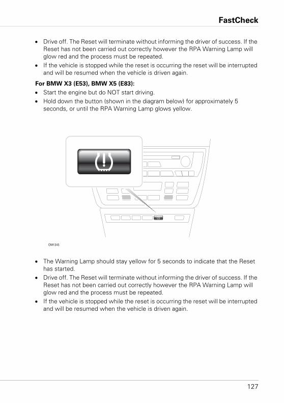
FastCheck
127
• Drive off. The Reset will terminate without informing the driver of success. If the Reset has not been carried out correctly however the RPA Warning Lamp will glow red and the process must be repeated.
• If the vehicle is stopped while the reset is occurring the reset will be interrupted and will be resumed when the vehicle is driven again.
For BMW X3 (E53), BMW X5 (E83):
• Start the engine but do NOT start driving.• Hold down the button (shown in the diagram below) for approximately 5
seconds, or until the RPA Warning Lamp glows yellow.
• The Warning Lamp should stay yellow for 5 seconds to indicate that the Reset has started.
• Drive off. The Reset will terminate without informing the driver of success. If the Reset has not been carried out correctly however the RPA Warning Lamp will glow red and the process must be repeated.
• If the vehicle is stopped while the reset is occurring the reset will be interrupted and will be resumed when the vehicle is driven again.
OM1345
FastCheck
128
Mini
Run-flat Reset (RPA – Tyre Deflation Detection)
The run-flat system monitors the pressure in the four mounted tyres while the vehicle is being driven.
The system will provide an alert whenever the inflation pressure in a tyre drops significantly in relation to the pressure of another tyre.
It is necessary to initiate the RPA reset process IMMEDIATELY after every tyre pressure correction, after a tyre or wheel change or after a trailer has been attached or detached. The reset MUST be started before driving the vehicle for the first time after one of the above events.
When a reset is required (due to a pressure change in one of the tyres) the vehicle will inform the driver by turning on the RPA Warning Lamp, which will glow red, and sounding an acoustic signal.
When the RPA Warning Lamp is on but the colour is yellow this indicates that the RPA system has failed or is malfunctioning. In this case the system must be diagnosed using a the scan function of the service tool.
The RPA reset process is as follows:• Start the engine but do NOT start driving.• Press the RPA Reset button (shown in the diagram below) and hold down for at
least 5 seconds, or until the RPA Warning Lamp on the indicator panel glows yellow.
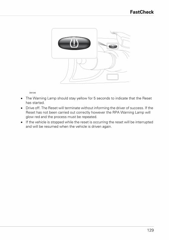
FastCheck
129
• The Warning Lamp should stay yellow for 5 seconds to indicate that the Reset has started.
• Drive off. The Reset will terminate without informing the driver of success. If the Reset has not been carried out correctly however the RPA Warning Lamp will glow red and the process must be repeated.
• If the vehicle is stopped while the reset is occurring the reset will be interrupted and will be resumed when the vehicle is driven again.
OM1346
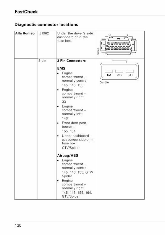
FastCheck
130
Diagnostic connector locations
Alfa Romeo J1962 Under the driver’s side dashboard or in the fuse box.
3-pin 3 Pin Connectors
EMS
• Engine compartment – normally centre:145, 146, 155
• Engine compartment – normally right:33
• Engine compartment – normally left:146
• Front door post – bottom:155, 164
• Under dashboard – passenger side or in fuse box:GTV/Spider
Airbag/ABS
• Engine compartment – normally centre:145, 146, 155, GTV/Spider
• Engine compartment – normally right:145, 146, 155, 164, GTV/Spider
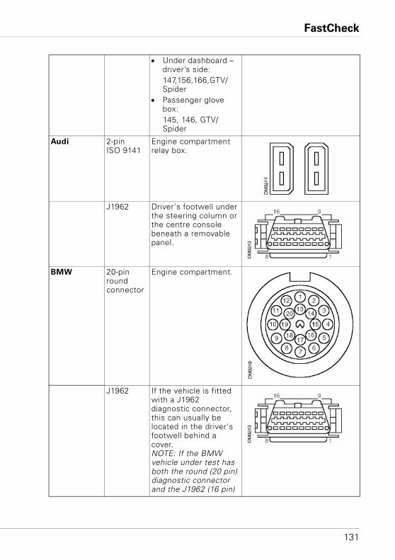
FastCheck
131
• Under dashboard – driver’s side:147,156,166,GTV/Spider
• Passenger glove box:145, 146, GTV/Spider
Audi 2-pin ISO 9141
Engine compartment relay box.
J1962 Driver's footwell under the steering column or the centre console beneath a removable panel.
BMW 20-pin round connector
Engine compartment.
J1962 If the vehicle is fitted with a J1962 diagnostic connector, this can usually be located in the driver's footwell behind a cover.NOTE: If the BMW vehicle under test has both the round (20 pin) diagnostic connector and the J1962 (16 pin)
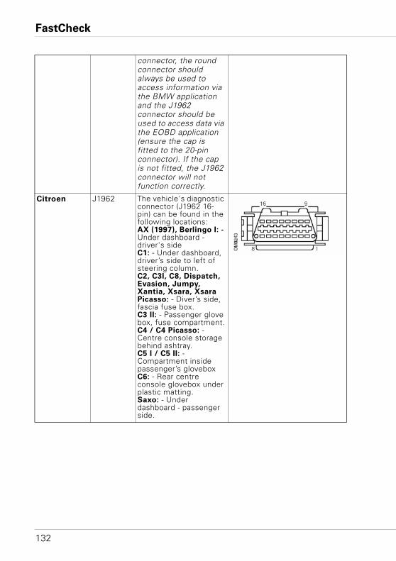
FastCheck
132
connector, the round connector should always be used to access information via the BMW application and the J1962 connector should be used to access data via the EOBD application (ensure the cap is fitted to the 20-pin connector). If the cap is not fitted, the J1962 connector will not function correctly.
Citroen J1962 The vehicle's diagnostic connector (J1962 16-pin) can be found in the following locations:AX (1997), Berlingo I: - Under dashboard - driver's sideC1: - Under dashboard, driver’s side to left of steering column.C2, C3I, C8, Dispatch, Evasion, Jumpy, Xantia, Xsara, Xsara Picasso: - Diver’s side, fascia fuse box.C3 II: - Passenger glove box, fuse compartment.C4 / C4 Picasso: - Centre console storage behind ashtray.C5 I / C5 II: - Compartment inside passenger’s gloveboxC6: - Rear centre console glovebox under plastic matting.Saxo: - Under dashboard - passenger side.
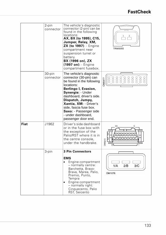
FastCheck
133
2-pin connector
The vehicle's diagnostic connector (2-pin) can be found in the following locations:AX, BX (to 1995), C15, Jumper, Relay, XM, ZX (to 1997): - Engine compartment near suspension turret or battery.BX (1996 on), ZX (1997 on): - Engine compartment fusebox.
30-pin connector
The vehicle's diagnostic connector (30-pin) can be found in the following locations:Berlingo I, Evasion, Synergie: - Under dashboard, driver's side.Dispatch, Jumpy, Xantia, XM: - Driver’s side, fascia fuse box.Saxo: - Passenger side - under dashboard, passenger door end.
Fiat J1962 Driver’s side dashboard or in the fuse box with the exception of the Palio/RST where it is in the centre console, under the handbrake.
3-pin 3 Pin Connectors
EMS• Engine compartment
– normally centre:Barchetta, Bravo-Brava, Marea, Palio, Premio, Punto, Tempra
• Engine compartment – normally right:Cinquecento, Palio RST, Seicento
1 2
TRW0055
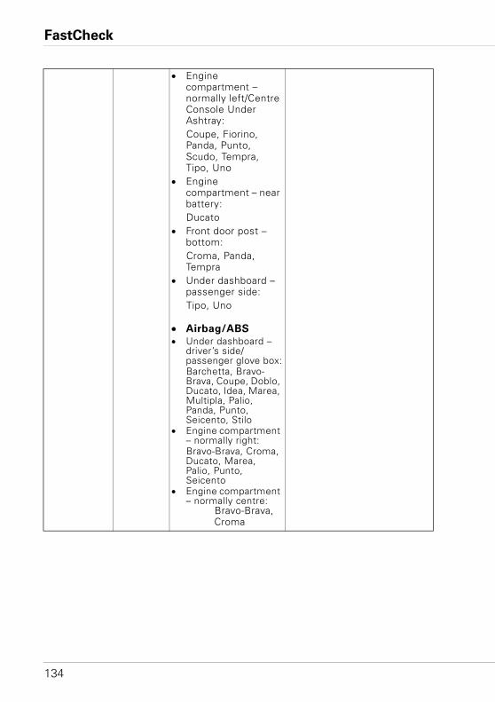
FastCheck
134
• Engine compartment – normally left/Centre Console Under Ashtray:Coupe, Fiorino, Panda, Punto, Scudo, Tempra, Tipo, Uno
• Engine compartment – near battery:Ducato
• Front door post – bottom:Croma, Panda, Tempra
• Under dashboard – passenger side:Tipo, Uno
• Airbag/ABS
• Under dashboard – driver’s side/passenger glove box:Barchetta, Bravo-Brava, Coupe, Doblo, Ducato, Idea, Marea, Multipla, Palio, Panda, Punto, Seicento, Stilo
• Engine compartment – normally right:Bravo-Brava, Croma, Ducato, Marea, Palio, Punto, Seicento
• Engine compartment – normally centre:
Bravo-Brava, Croma
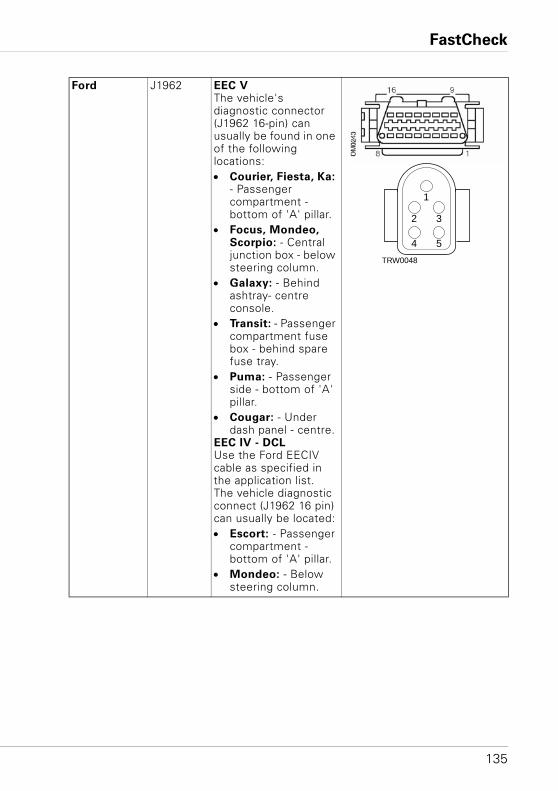
FastCheck
135
Ford J1962 EEC VThe vehicle's diagnostic connector (J1962 16-pin) can usually be found in one of the following locations:• Courier, Fiesta, Ka:
- Passenger compartment - bottom of 'A' pillar.
• Focus, Mondeo, Scorpio: - Central junction box - below steering column.
• Galaxy: - Behind ashtray- centre console.
• Transit: - Passenger compartment fuse box - behind spare fuse tray.
• Puma: - Passenger side - bottom of 'A' pillar.
• Cougar: - Under dash panel - centre.
EEC IV - DCLUse the Ford EECIV cable as specified in the application list.The vehicle diagnostic connect (J1962 16 pin) can usually be located:• Escort: - Passenger
compartment - bottom of 'A' pillar.
• Mondeo: - Below steering column.
1
2 3
4 5
TRW0048
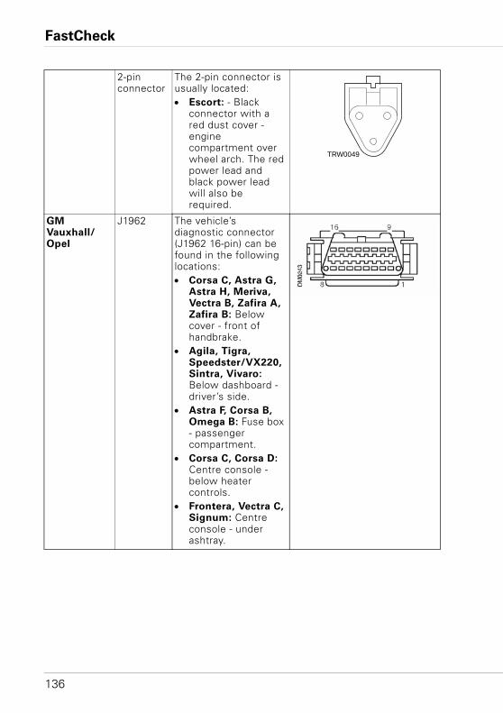
FastCheck
136
2-pin connector
The 2-pin connector is usually located:• Escort: - Black
connector with a red dust cover - engine compartment over wheel arch. The red power lead and black power lead will also be required.
GM Vauxhall/Opel
J1962 The vehicle’s diagnostic connector (J1962 16-pin) can be found in the following locations:• Corsa C, Astra G,
Astra H, Meriva, Vectra B, Zafira A, Zafira B: Below cover - front of handbrake.
• Agila, Tigra, Speedster/VX220, Sintra, Vivaro:Below dashboard - driver’s side.
• Astra F, Corsa B, Omega B: Fuse box - passenger compartment.
• Corsa C, Corsa D: Centre console - below heater controls.
• Frontera, Vectra C, Signum: Centre console - under ashtray.
TRW0049
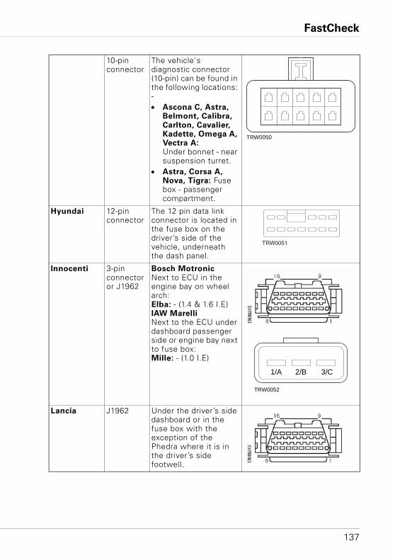
FastCheck
137
10-pin connector
The vehicle's diagnostic connector (10-pin) can be found in the following locations: -• Ascona C, Astra,
Belmont, Calibra, Carlton, Cavalier, Kadette, Omega A, Vectra A:Under bonnet - near suspension turret.
• Astra, Corsa A, Nova, Tigra: Fuse box - passenger compartment.
Hyundai 12-pin connector
The 12 pin data link connector is located in the fuse box on the driver’s side of the vehicle, underneath the dash panel.
Innocenti 3-pin connector or J1962
Bosch MotronicNext to ECU in the engine bay on wheel arch: Elba: - (1.4 & 1.6 I.E)IAW MarelliNext to the ECU under dashboard passenger side or engine bay next to fuse box:Mille: - (1.0 I.E)
Lancia J1962 Under the driver’s side dashboard or in the fuse box with the exception of the Phedra where it is in the driver’s side footwell.
TRW0050
TRW0051
1/A 2/B 3/C
TRW0052
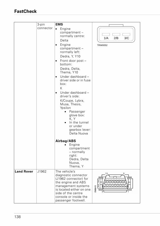
FastCheck
138
3-pin connector
EMS
• Engine compartment – normally centre:Delta
• Engine compartment – normally left:Dedra, Y, Y10
• Front door post – bottom:Dedra, Delta, Thema, Y10
• Under dashboard – driver side or in fuse box:K
• Under dashboard – driver’s side:K/Coupe, Lybra, Musa, Thesis, Ypsilon
• Passenger glove box:K, Y
• In the tunnel or under gearbox lever:Delta Nuova
Airbag/ABS• Engine
compartment – normally right:Dedra, Delta Nuova, Thema, Y
Land Rover J1962 The vehicle’s diagnostic connector (J1962 connector) for the engine and ABS management systems is located either on one side of the centre console or inside the passenger footwell.
1/A 2/B 3/C
TRW0052
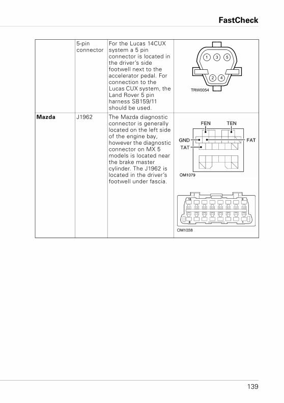
FastCheck
139
5-pin connector
For the Lucas 14CUX system a 5 pin connector is located in the driver’s side footwell next to the accelerator pedal. For connection to the Lucas CUX system, the Land Rover 5 pin harness SB159/11 should be used.
Mazda J1962 The Mazda diagnostic connector is generally located on the left side of the engine bay, however the diagnostic connector on MX 5 models is located near the brake master cylinder. The J1962 is located in the driver’s footwell under fascia.
1
2 4
3 5
TRW0054
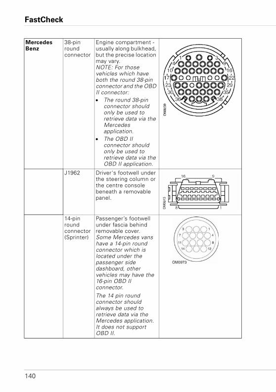
FastCheck
140
Mercedes Benz
38-pin round connector
Engine compartment - usually along bulkhead, but the precise location may vary. NOTE: For those vehicles which have both the round 38-pin connector and the OBD II connector:• The round 38-pin
connector should only be used to retrieve data via the Mercedes application.
• The OBD II connector should only be used to retrieve data via the OBD II application.
J1962 Driver's footwell under the steering column or the centre console beneath a removable panel.
14-pin round connector (Sprinter)
Passenger’s footwell under fascia behind removable cover.Some Mercedes vans have a 14-pin round connector which is located under the passenger side dashboard, other vehicles may have the 16-pin OBD II connector.The 14 pin round connector should always be used to retrieve data via the Mercedes application. It does not support OBD II.
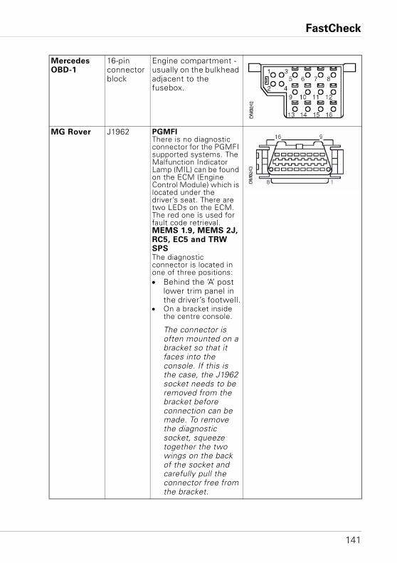
FastCheck
141
Mercedes OBD-1
16-pin connector block
Engine compartment - usually on the bulkhead adjacent to the fusebox.
MG Rover J1962 PGMFIThere is no diagnostic connector for the PGMFI supported systems. The Malfunction Indicator Lamp (MIL) can be found on the ECM (Engine Control Module) which is located under the driver’s seat. There are two LEDs on the ECM. The red one is used for fault code retrieval.MEMS 1.9, MEMS 2J, RC5, EC5 and TRW SPSThe diagnostic connector is located in one of three positions:• Behind the ‘A’ post
lower trim panel in the driver’s footwell.
• On a bracket inside the centre console.
The connector is often mounted on a bracket so that it faces into the console. If this is the case, the J1962 socket needs to be removed from the bracket before connection can be made. To remove the diagnostic socket, squeeze together the two wings on the back of the socket and carefully pull the connector free from the bracket.
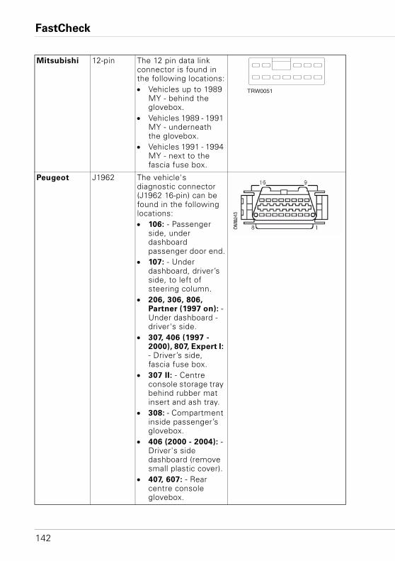
FastCheck
142
Mitsubishi 12-pin The 12 pin data link connector is found in the following locations:• Vehicles up to 1989
MY - behind the glovebox.
• Vehicles 1989 - 1991 MY - underneath the glovebox.
• Vehicles 1991 - 1994 MY - next to the fascia fuse box.
Peugeot J1962 The vehicle's diagnostic connector (J1962 16-pin) can be found in the following locations:• 106: - Passenger
side, under dashboard passenger door end.
• 107: - Under dashboard, driver’s side, to left of steering column.
• 206, 306, 806, Partner (1997 on): - Under dashboard - driver's side.
• 307, 406 (1997 - 2000), 807, Expert I: - Driver’s side, fascia fuse box.
• 307 II: - Centre console storage tray behind rubber mat insert and ash tray.
• 308: - Compartment inside passenger’s glovebox.
• 406 (2000 - 2004): - Driver's side dashboard (remove small plastic cover).
• 407, 607: - Rear centre console glovebox.
TRW0051
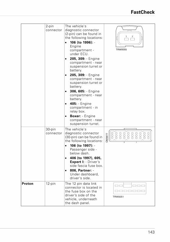
FastCheck
143
2-pin connector
The vehicle's diagnostic connector (2-pin) can be found in the following locations:• 106 (to 1996): -
Engine compartment - under ECU.
• 205, 309: - Engine compartment - near suspension turret or battery.
• 205, 309: - Engine compartment - near suspension turret or battery.
• 306, 605: - Engine compartment - near battery.
• 405: - Engine compartment - in relay box.
• Boxer: - Engine compartment - near suspension turret.
30-pin connector
The vehicle's diagnostic connector (30-pin) can be found in the following locations:• 106 (to 1997): -
Passenger side - below dash.
• 406 (to 1997), 605, Expert I: - Driver’s side fascia fuse box.
• 806, Partner: - Under dashboard, driver's side.
Proton 12-pin The 12 pin data link connector is located in the fuse box on the driver’s side of the vehicle, underneath the dash panel.
1 2
TRW0055
TRW0051
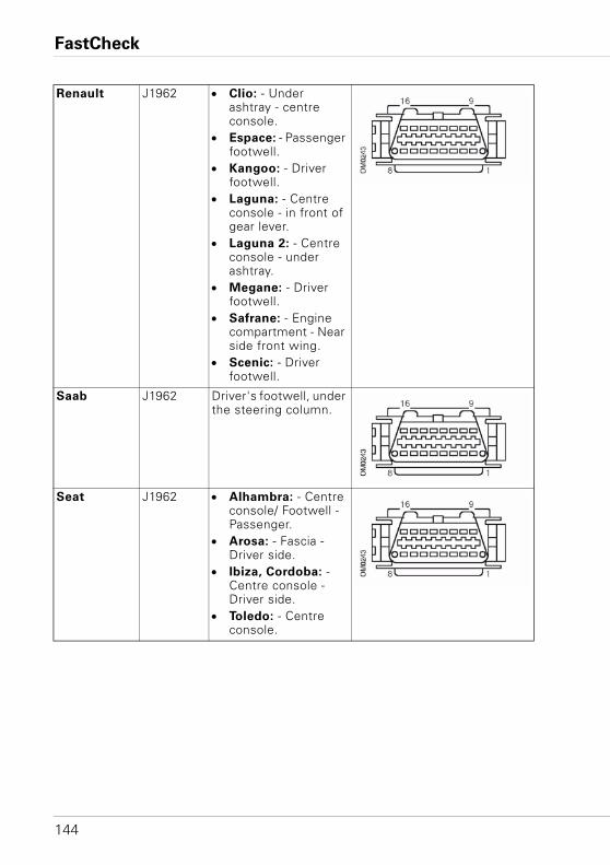
FastCheck
144
Renault J1962 • Clio: - Under ashtray - centre console.
• Espace: - Passenger footwell.
• Kangoo: - Driver footwell.
• Laguna: - Centre console - in front of gear lever.
• Laguna 2: - Centre console - under ashtray.
• Megane: - Driver footwell.
• Safrane: - Engine compartment - Near side front wing.
• Scenic: - Driver footwell.
Saab J1962 Driver's footwell, under the steering column.
Seat J1962 • Alhambra: - Centre console/ Footwell - Passenger.
• Arosa: - Fascia - Driver side.
• Ibiza, Cordoba: - Centre console - Driver side.
• Toledo: - Centre console.
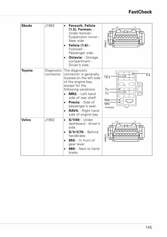
FastCheck
145
Skoda J1962 • Favourit, Felicia (1.3), Forman: - Under bonnet - Suspension turret - Near side.
• Felicia (1.6): - Footwell - Passenger side.
• Octavia: - Storage compartment - Driver’s side.
Toyota Diagnostic connector
The diagnostic connector is generally located on the left side of the engine bay, except for the following variations:• MR2: - Left hand
side of rear shelf.• Previa: - Side of
passenger’s seat.• RAV4: - Right hand
side of engine bay.
Volvo J1962 • S/V40: - Under dashboard - driver’s side.
• S/V/C70: - Behind handbrake.
• 850: - In front of gear lever.
• 960: - Next to hand brake.
TE1E1
TsTc
WbWa
TRW0056
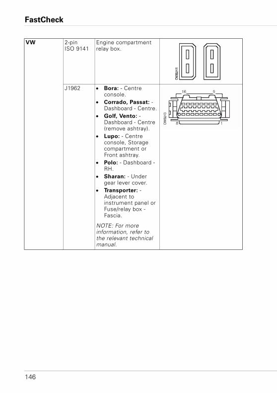
FastCheck
146
VW 2-pin ISO 9141
Engine compartment relay box.
J1962 • Bora: - Centre console.
• Corrado, Passat: - Dashboard - Centre.
• Golf, Vento: - Dashboard - Centre (remove ashtray).
• Lupo: - Centre console, Storage compartment or Front ashtray.
• Polo: - Dashboard - RH.
• Sharan: - Under gear lever cover.
• Transporter: - Adjacent to instrument panel or Fuse/relay box - Fascia.
NOTE: For more information, refer to the relevant technical manual.
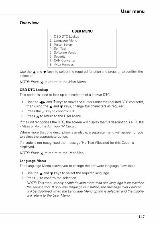
User menu
147
User menuOverview
Use the and keys to select the required function and press to confirm the selection.
NOTE: Press to return to the Main Menu.
OBD DTC Lookup
This option is used to look up a description of a known DTC.
1. Use the and keys to move the cursor under the required DTC character, then using the and keys, change the characters as required.
2. Press the key to confirm DTC.3. Press to return to the User Menu.
If the unit recognises the DTC, the screen will display the full description. i.e. P0100 - Mass or Volume Air Flow 'A' Circuit.
Where more that one description is available, a separate menu will appear for you to select the appropriate option.
If a code is not recognised the message 'No Text Allocated for this Code' is displayed.
NOTE: Press to return to the User Menu.
Language Menu
The Language Menu allows you to change the software language if available.
1. Use the and keys to select the required language.2. Press to confirm the selection.
NOTE: This menu is only enabled when more than one language is installed on the service tool. If only one language is installed, the message 'Not Enabled' will be displayed when the Language Menu option is selected and the display will return to the User Menu.
USER MENU
1. OBD DTC Lookup2. Language Menu3. Tester Setup4. Self Test5. Software Version6. Security7. CAN Converter8. iMux Harness
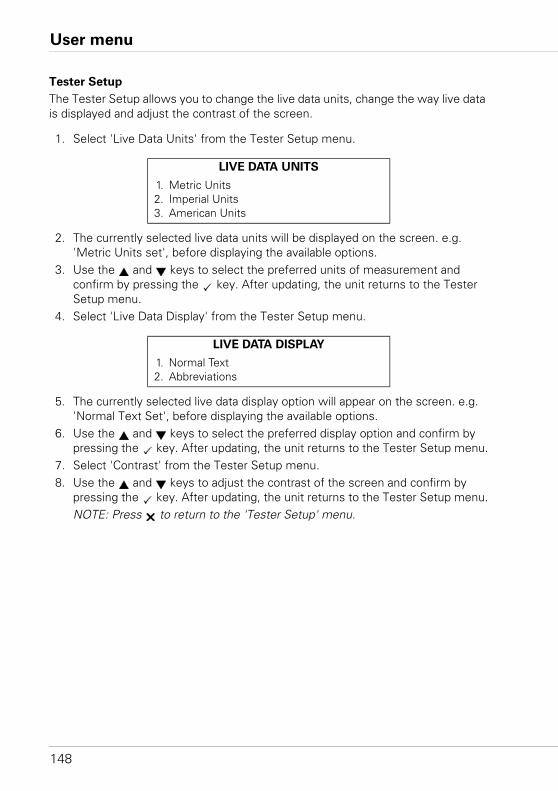
User menu
148
Tester Setup
The Tester Setup allows you to change the live data units, change the way live data is displayed and adjust the contrast of the screen.
1. Select 'Live Data Units' from the Tester Setup menu.
2. The currently selected live data units will be displayed on the screen. e.g. 'Metric Units set', before displaying the available options.
3. Use the and keys to select the preferred units of measurement and confirm by pressing the key. After updating, the unit returns to the Tester Setup menu.
4. Select 'Live Data Display' from the Tester Setup menu.
5. The currently selected live data display option will appear on the screen. e.g. 'Normal Text Set', before displaying the available options.
6. Use the and keys to select the preferred display option and confirm by pressing the key. After updating, the unit returns to the Tester Setup menu.
7. Select 'Contrast' from the Tester Setup menu.8. Use the and keys to adjust the contrast of the screen and confirm by
pressing the key. After updating, the unit returns to the Tester Setup menu.NOTE: Press to return to the 'Tester Setup' menu.
LIVE DATA UNITS
1. Metric Units2. Imperial Units3. American Units
LIVE DATA DISPLAY
1. Normal Text2. Abbreviations
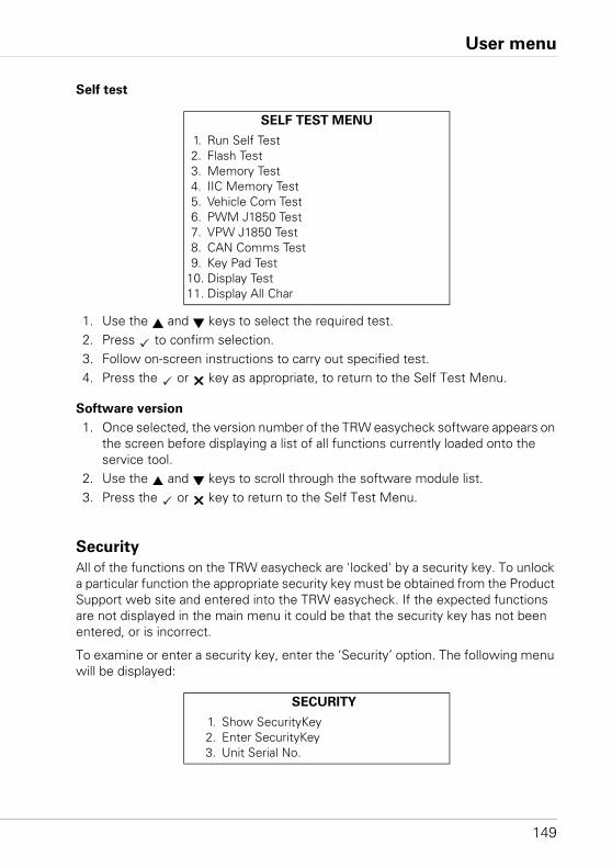
User menu
149
Self test
1. Use the and keys to select the required test.2. Press to confirm selection.3. Follow on-screen instructions to carry out specified test.4. Press the or key as appropriate, to return to the Self Test Menu.
Software version
1. Once selected, the version number of the TRW easycheck software appears on the screen before displaying a list of all functions currently loaded onto the service tool.
2. Use the and keys to scroll through the software module list.3. Press the or key to return to the Self Test Menu.
Security
All of the functions on the TRW easycheck are 'locked' by a security key. To unlock a particular function the appropriate security key must be obtained from the Product Support web site and entered into the TRW easycheck. If the expected functions are not displayed in the main menu it could be that the security key has not been entered, or is incorrect.
To examine or enter a security key, enter the ‘Security’ option. The following menu will be displayed:
SELF TEST MENU
1. Run Self Test2. Flash Test3. Memory Test4. IIC Memory Test5. Vehicle Com Test6. PWM J1850 Test7. VPW J1850 Test8. CAN Comms Test9. Key Pad Test
10. Display Test11. Display All Char
SECURITY
1. Show SecurityKey2. Enter SecurityKey3. Unit Serial No.
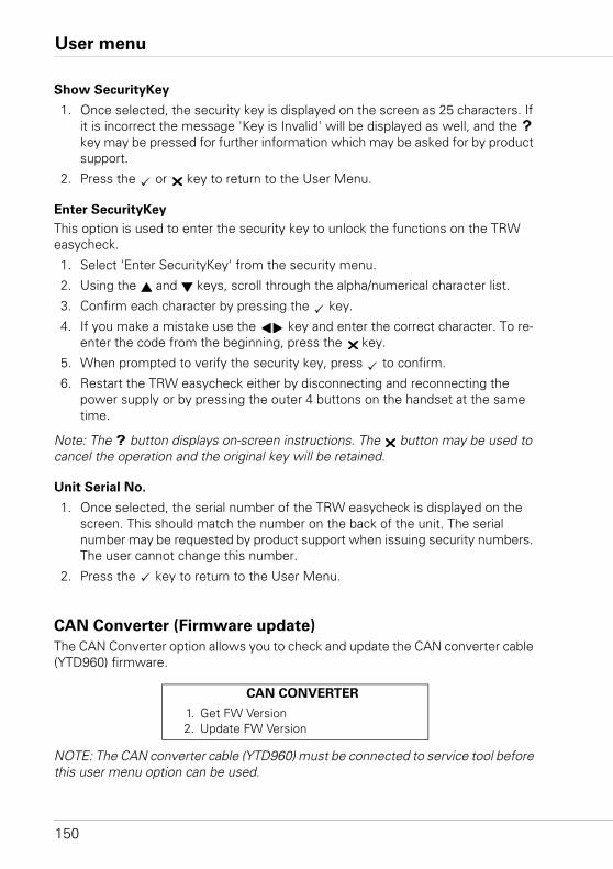
User menu
150
Show SecurityKey
1. Once selected, the security key is displayed on the screen as 25 characters. If it is incorrect the message 'Key is Invalid' will be displayed as well, and the key may be pressed for further information which may be asked for by product support.
2. Press the or key to return to the User Menu.
Enter SecurityKey
This option is used to enter the security key to unlock the functions on the TRW easycheck.
1. Select 'Enter SecurityKey' from the security menu.
2. Using the and keys, scroll through the alpha/numerical character list.
3. Confirm each character by pressing the key.
4. If you make a mistake use the key and enter the correct character. To re-enter the code from the beginning, press the key.
5. When prompted to verify the security key, press to confirm.
6. Restart the TRW easycheck either by disconnecting and reconnecting the power supply or by pressing the outer 4 buttons on the handset at the same time.
Note: The button displays on-screen instructions. The button may be used to cancel the operation and the original key will be retained.
Unit Serial No.
1. Once selected, the serial number of the TRW easycheck is displayed on the screen. This should match the number on the back of the unit. The serial number may be requested by product support when issuing security numbers. The user cannot change this number.
2. Press the key to return to the User Menu.
CAN Converter (Firmware update)
The CAN Converter option allows you to check and update the CAN converter cable (YTD960) firmware.
NOTE: The CAN converter cable (YTD960) must be connected to service tool before this user menu option can be used.
CAN CONVERTER
1. Get FW Version2. Update FW Version
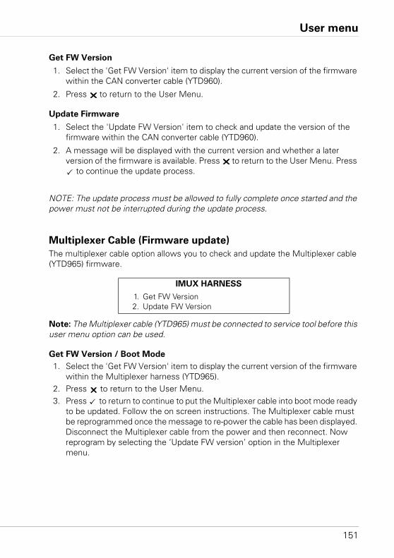
User menu
151
Get FW Version
1. Select the 'Get FW Version' item to display the current version of the firmware within the CAN converter cable (YTD960).
2. Press to return to the User Menu.
Update Firmware
1. Select the 'Update FW Version' item to check and update the version of the firmware within the CAN converter cable (YTD960).
2. A message will be displayed with the current version and whether a later version of the firmware is available. Press to return to the User Menu. Press
to continue the update process.
NOTE: The update process must be allowed to fully complete once started and the power must not be interrupted during the update process.
Multiplexer Cable (Firmware update)
The multiplexer cable option allows you to check and update the Multiplexer cable (YTD965) firmware.
Note: The Multiplexer cable (YTD965) must be connected to service tool before this user menu option can be used.
Get FW Version / Boot Mode
1. Select the 'Get FW Version' item to display the current version of the firmware within the Multiplexer harness (YTD965).
2. Press to return to the User Menu.3. Press to return to continue to put the Multiplexer cable into boot mode ready
to be updated. Follow the on screen instructions. The Multiplexer cable must be reprogrammed once the message to re-power the cable has been displayed. Disconnect the Multiplexer cable from the power and then reconnect. Now reprogram by selecting the ‘Update FW version’ option in the Multiplexer menu.
IMUX HARNESS
1. Get FW Version2. Update FW Version
User menu
152
Update Firmware
This process should only be performed after the Multiplexer cable has been placed into boot mode.
1. Select the 'Update FW Version' item the Multiplexer cable will now be updated.2. A message will be displayed to show the firmware has been updated. Press
to continue the update process.NOTE: The update process must be allowed to fully complete once started and the power must not be interrupted during the update process.
General information
153
General informationCleaning
To maintain the condition and serviceability of the service tool, it is advisable to fol-low the cleaning procedures below:
WARNING: Do not use solvents such as petroleum based cleaning agents, ac-
etone, petrol, trichlorethylene etc. These types of harsh solvent may seriously
damage the plastic casing. Do not even spray or pour this type of cleaner onto
a cleaning cloth.
WARNING: The service tool is not waterproof. Always dry the unit thoroughly
after cleaning or if it has been subject to accidental spillage.
The manufacturer recommends that you periodically inspect and clean the following parts of the service tool:• The case• The display screen• The keypad• Adaptor cables and connectors
To clean the service tool, or any of its cables or connectors, apply a mild detergent solution to a soft clean cloth that has been suitably dampened.
WARNING: Before cleaning, disconnect the service tool from the vehicle.
Display screen
During normal everyday use, the screen may become dusty or covered in grime. To clean the screen, always use a soft, clean, antistatic cloth. If any stubborn stains or marks remain, use a non-abrasive glass cleaner applied to a soft, clean cloth. Gently wipe the cloth across the display until the marks have been removed.
Software updates
For the latest information on software updates go to:
www.trwaftermarket.com/easycheck
General information
154
Specification
TRW easycheck complies with ISO/DIS 15031 Part 4 as an EOBD service tool.
Voltage requirements - 8.0 volts to 16.0 volts DC
Current requirement - 750mA max.
Display - 20 characters by 4 lines LCD with LED back light
Operating Temperature range - 0°C to 50°C
Declaration of Conformity
The TRW easycheck is CE marked and complies with the following directives:
EN55022:1998 - ITE Emissions (Class A)
EN50082-1:1998 - Generic EMC Immunity
EN60950:1992 - Safety Requirements
FCC47 Part 15 - Radio Frequency Devices (Class A)
A copy of the Declaration of Conformity certificate is available on request from the manufacturer or your supplier.
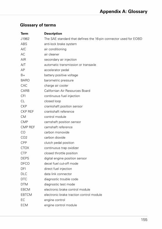
Appendix A: Glossary
155
Glossary
Glossary of terms
Term Description
J1962 The SAE standard that defines the 16-pin connector used for EOBD
ABS anti-lock brake system
A/C air conditioning
AC air cleaner
AIR secondary air injection
A/T automatic transmission or transaxle
AP accelerator pedal
B+ battery positive voltage
BARO barometric pressure
CAC charge air cooler
CARB Californian Air Resources Board
CFI continuous fuel injection
CL closed loop
CKP crankshaft position sensor
CKP REF crankshaft reference
CM control module
CMP camshaft position sensor
CMP REF camshaft reference
CO carbon monoxide
CO2 carbon dioxide
CPP clutch pedal position
CTOX continuous trap oxidizer
CTP closed throttle position
DEPS digital engine position sensor
DFCO decel fuel cut-off mode
DFI direct fuel injection
DLC data link connector
DTC diagnostic trouble code
DTM diagnostic test mode
EBCM electronic brake control module
EBTCM electronic brake traction control module
EC engine control
ECM engine control module
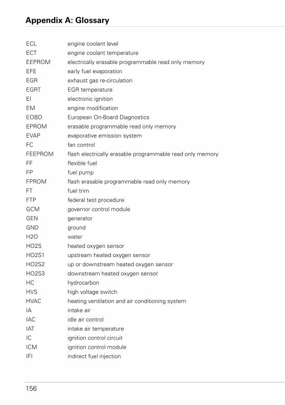
Appendix A: Glossary
156
ECL engine coolant level
ECT engine coolant temperature
EEPROM electrically erasable programmable read only memory
EFE early fuel evaporation
EGR exhaust gas re-circulation
EGRT EGR temperature
EI electronic ignition
EM engine modification
EOBD European On-Board Diagnostics
EPROM erasable programmable read only memory
EVAP evaporative emission system
FC fan control
FEEPROM flash electrically erasable programmable read only memory
FF flexible fuel
FP fuel pump
FPROM flash erasable programmable read only memory
FT fuel trim
FTP federal test procedure
GCM governor control module
GEN generator
GND ground
H2O water
HO2S heated oxygen sensor
HO2S1 upstream heated oxygen sensor
HO2S2 up or downstream heated oxygen sensor
HO2S3 downstream heated oxygen sensor
HC hydrocarbon
HVS high voltage switch
HVAC heating ventilation and air conditioning system
IA intake air
IAC idle air control
IAT intake air temperature
IC ignition control circuit
ICM ignition control module
IFI indirect fuel injection
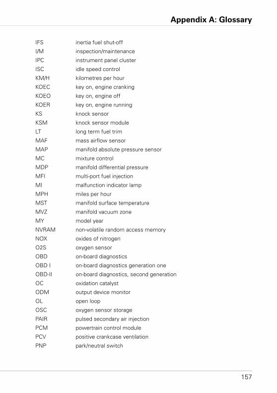
Appendix A: Glossary
157
IFS inertia fuel shut-off
I/M inspection/maintenance
IPC instrument panel cluster
ISC idle speed control
KM/H kilometres per hour
KOEC key on, engine cranking
KOEO key on, engine off
KOER key on, engine running
KS knock sensor
KSM knock sensor module
LT long term fuel trim
MAF mass airflow sensor
MAP manifold absolute pressure sensor
MC mixture control
MDP manifold differential pressure
MFI multi-port fuel injection
MI malfunction indicator lamp
MPH miles per hour
MST manifold surface temperature
MVZ manifold vacuum zone
MY model year
NVRAM non-volatile random access memory
NOX oxides of nitrogen
O2S oxygen sensor
OBD on-board diagnostics
OBD I on-board diagnostics generation one
OBD-II on-board diagnostics, second generation
OC oxidation catalyst
ODM output device monitor
OL open loop
OSC oxygen sensor storage
PAIR pulsed secondary air injection
PCM powertrain control module
PCV positive crankcase ventilation
PNP park/neutral switch
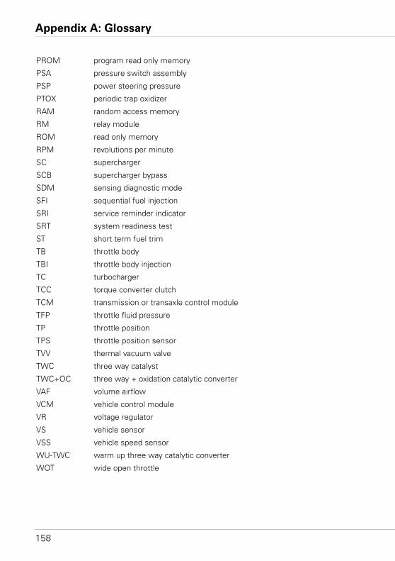
Appendix A: Glossary
158
PROM program read only memory
PSA pressure switch assembly
PSP power steering pressure
PTOX periodic trap oxidizer
RAM random access memory
RM relay module
ROM read only memory
RPM revolutions per minute
SC supercharger
SCB supercharger bypass
SDM sensing diagnostic mode
SFI sequential fuel injection
SRI service reminder indicator
SRT system readiness test
ST short term fuel trim
TB throttle body
TBI throttle body injection
TC turbocharger
TCC torque converter clutch
TCM transmission or transaxle control module
TFP throttle fluid pressure
TP throttle position
TPS throttle position sensor
TVV thermal vacuum valve
TWC three way catalyst
TWC+OC three way + oxidation catalytic converter
VAF volume airflow
VCM vehicle control module
VR voltage regulator
VS vehicle sensor
VSS vehicle speed sensor
WU-TWC warm up three way catalytic converter
WOT wide open throttle
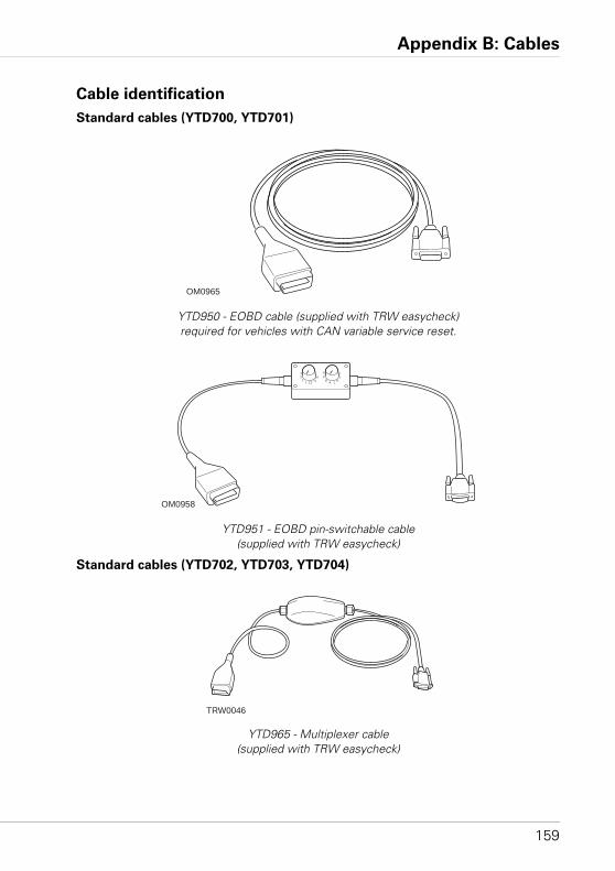
Appendix B: Cables
159
Cables
Cable identification
Standard cables (YTD700, YTD701)
YTD950 - EOBD cable (supplied with TRW easycheck) required for vehicles with CAN variable service reset.
YTD951 - EOBD pin-switchable cable (supplied with TRW easycheck)
Standard cables (YTD702, YTD703, YTD704)
YTD965 - Multiplexer cable(supplied with TRW easycheck)
OM0965
OM0958
1 12
432
1011
A L
DC
B
IJ
K
TRW0046
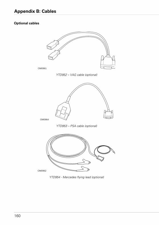
Appendix B: Cables
160
Optional cables
YTD952 – VAG cable (optional)
YTD953 – PSA cable (optional)
YTD954 - Mercedes flying lead (optional)
OM0961
OM0964
OM0962
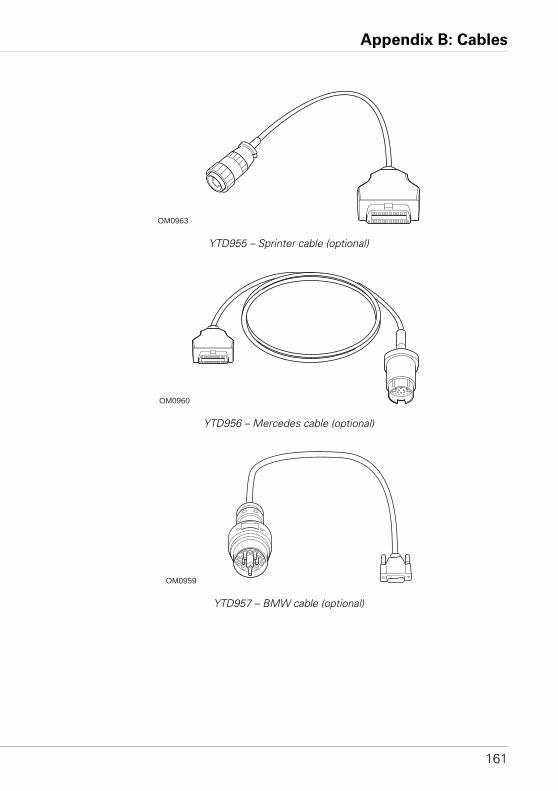
Appendix B: Cables
161
YTD955 – Sprinter cable (optional)
YTD956 – Mercedes cable (optional)
YTD957 – BMW cable (optional)
OM0963
OM0960
OM0959
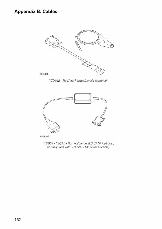
Appendix B: Cables
162
YTD958 - Fiat/Alfa Romeo/Lancia (optional)
YTD959 - Fiat/Alfa Romeo/Lancia (LS CAN) (optional, not required with YTD965 - Multiplexer cable)
OM1388
OM1106
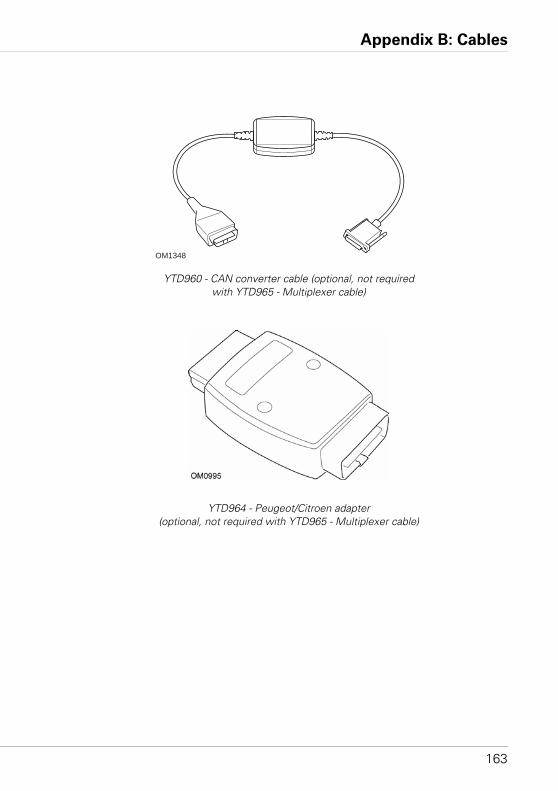
Appendix B: Cables
163
YTD960 - CAN converter cable (optional, not required with YTD965 - Multiplexer cable)
YTD964 - Peugeot/Citroen adapter (optional, not required with YTD965 - Multiplexer cable)
OM1348
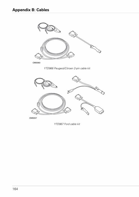
Appendix B: Cables
164
YTD966 Peugeot/Citroen 2-pin cable kit
YTD967 Ford cable kit
OM0060
OM0057
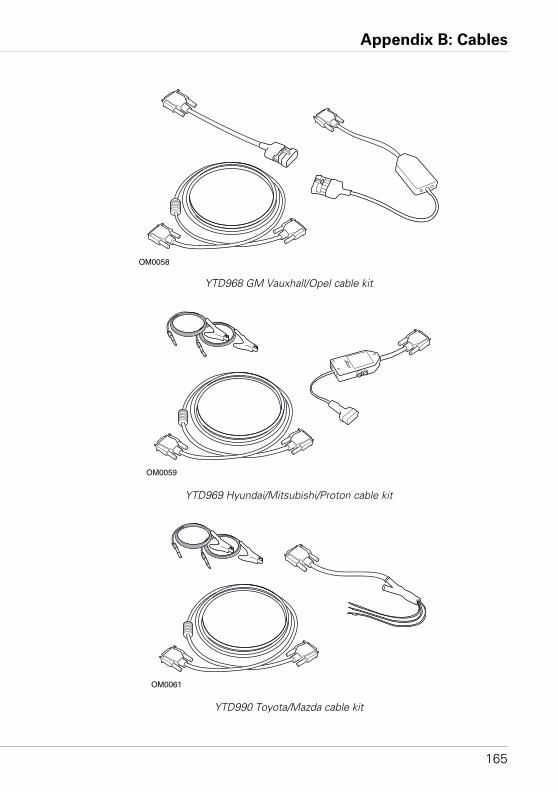
Appendix B: Cables
165
YTD968 GM Vauxhall/Opel cable kit
YTD969 Hyundai/Mitsubishi/Proton cable kit
YTD990 Toyota/Mazda cable kit
OM0058
OM0059
OM0061
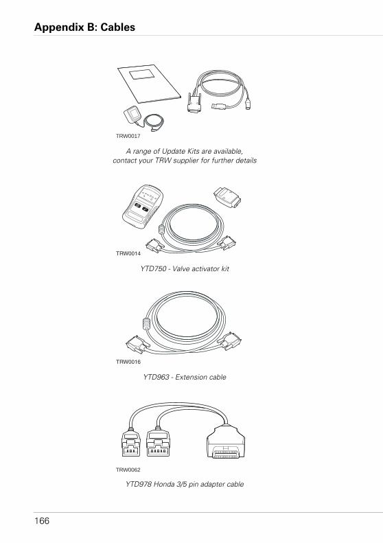
Appendix B: Cables
166
A range of Update Kits are available, contact your TRW supplier for further details
YTD750 - Valve activator kit
YTD963 - Extension cable
YTD978 Honda 3/5 pin adapter cable
TRW0017
TRW0014
OmiDetect
TRW0016
TRW0062
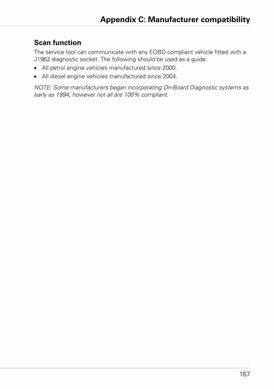
Appendix C: Manufacturer compatibility
167
Manufacturer compatibility
Scan function
The service tool can communicate with any EOBD compliant vehicle fitted with a J1962 diagnostic socket. The following should be used as a guide.• All petrol engine vehicles manufactured since 2000.• All diesel engine vehicles manufactured since 2004.
NOTE: Some manufacturers began incorporating On-Board Diagnostic systems as early as 1994, however not all are 100% compliant.
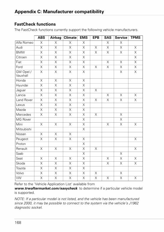
Appendix C: Manufacturer compatibility
168
FastCheck functions
The FastCheck functions currently support the following vehicle manufacturers.
Refer to the 'Vehicle Application List' available from www.trwaftermarket.com/easycheck to determine if a particular vehicle model is supported.
NOTE: If a particular model is not listed, and the vehicle has been manufactured since 2000, it may be possible to connect to the system via the vehicle’s J1962 diagnostic socket.
ABS Airbag Climate EMS EPB SAS Service TPMS
Alfa Romeo X X X X X XAudi X X X X X X X XBMW X X X X X X X XCitroen X X X X XFiat X X X X X X XFord X X X X X X X XGM Opel / Vauxhall
X X X X X X
Honda X X X XHyundai X X X XJaguar X X X X XLancia X X X X X X XLand Rover X X X X X X X XLexus X X X XMazda X X X XMercedes X X X X X XMG Rover X XMini X X X X X X XMitsubishi XNissan X X XPeugeot X X X X XProton XRenault X X X X X XSaab X XSeat X X X X X X XSkoda X X X X X X XToyota X X X XVolvo X X X X X XVW X X X X X X X X
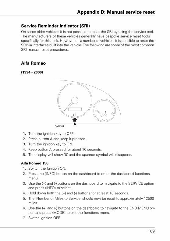
Appendix D: Manual service reset
169
Manual service reset
Service Reminder Indicator (SRI)
On some older vehicles it is not possible to reset the SRI by using the service tool. The manufacturers of these vehicles generally have bespoke service reset tools specifically for this task. However on a number of vehicles, it is possible to reset the SRI via interfaces built into the vehicle. The following are some of the most common SRI manual reset procedures.
Alfa Romeo
(1994 - 2000)
1. Turn the ignition key to OFF.2. Press button A and keep it pressed.3. Turn the ignition key to ON. 4. Keep button A pressed for about 10 seconds. 5. The display will show '0' and the spanner symbol will disappear.
Alfa Romeo 156
1. Switch the Ignition ON.2. Press the (INFO) button on the dashboard to enter the dashboard functions
menu.3. Use the (+) and (-) buttons on the dashboard to navigate to the SERVICE option
and press (INFO) to select.4. Hold down both the (+) and (-) buttons for at least 10 seconds.5. The 'Number of Miles to Service' should now be reset to approximately 12500
miles.6. Use the (+) and (-) buttons on the dashboard to navigate to the END MENU op-
tion and press (MODE) to exit the functions menu.7. Switch ignition OFF.
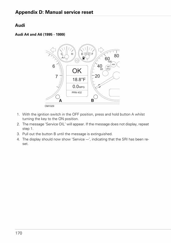
Appendix D: Manual service reset
170
Audi
Audi A4 and A6 (1995 - 1999)
1. With the ignition switch in the OFF position, press and hold button A whilst turning the key to the ON position.
2. The message ‘Service OIL’ will appear. If the message does not display, repeat step 1.
3. Pull out the button B until the message is extinguished. 4. The display should now show ‘Service ---’, indicating that the SRI has been re-
set.
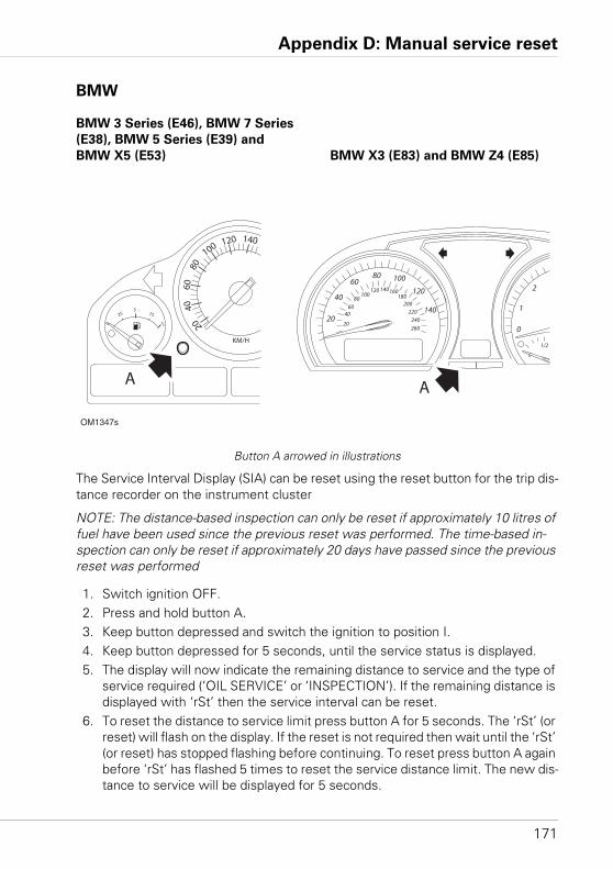
Appendix D: Manual service reset
171
BMW
BMW 3 Series (E46), BMW 7 Series
(E38), BMW 5 Series (E39) and
BMW X5 (E53) BMW X3 (E83) and BMW Z4 (E85)
Button A arrowed in illustrations
The Service Interval Display (SIA) can be reset using the reset button for the trip dis-tance recorder on the instrument cluster
NOTE: The distance-based inspection can only be reset if approximately 10 litres of fuel have been used since the previous reset was performed. The time-based in-spection can only be reset if approximately 20 days have passed since the previous reset was performed
1. Switch ignition OFF.2. Press and hold button A.3. Keep button depressed and switch the ignition to position I.4. Keep button depressed for 5 seconds, until the service status is displayed.5. The display will now indicate the remaining distance to service and the type of
service required (‘OIL SERVICE’ or ‘INSPECTION’). If the remaining distance is displayed with ‘rSt’ then the service interval can be reset.
6. To reset the distance to service limit press button A for 5 seconds. The ‘rSt’ (or reset) will flash on the display. If the reset is not required then wait until the ‘rSt’ (or reset) has stopped flashing before continuing. To reset press button A again before ‘rSt’ has flashed 5 times to reset the service distance limit. The new dis-tance to service will be displayed for 5 seconds.
OM1347s
A A
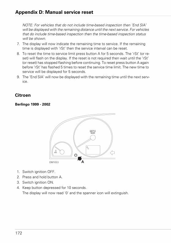
Appendix D: Manual service reset
172
NOTE: For vehicles that do not include time-based inspection then ‘End SIA’ will be displayed with the remaining distance until the next service. For vehicles that do include time-based inspection then the time-based inspection status will be shown.
7. The display will now indicate the remaining time to service. If the remaining time is displayed with ‘rSt’ then the service interval can be reset.
8. To reset the time to service limit press button A for 5 seconds. The ‘rSt’ (or re-set) will flash on the display. If the reset is not required then wait until the ‘rSt’ (or reset) has stopped flashing before continuing. To reset press button A again before ‘rSt’ has flashed 5 times to reset the service time limit. The new time to service will be displayed for 5 seconds.
9. The ‘End SIA’ will now be displayed with the remaining time until the next serv-ice.
Citroen
Berlingo 1999 - 2002
1. Switch ignition OFF.2. Press and hold button A.3. Switch ignition ON.4. Keep button depressed for 10 seconds.
The display will now read '0' and the spanner icon will extinguish.
OM1053 A
km/hMPH
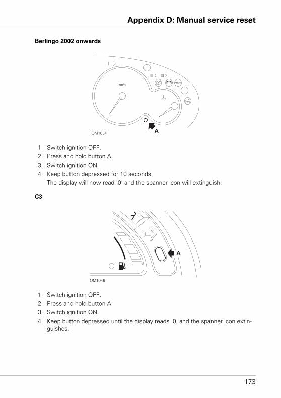
Appendix D: Manual service reset
173
Berlingo 2002 onwards
1. Switch ignition OFF.2. Press and hold button A.3. Switch ignition ON.4. Keep button depressed for 10 seconds.
The display will now read '0' and the spanner icon will extinguish.
C3
1. Switch ignition OFF.2. Press and hold button A.3. Switch ignition ON.4. Keep button depressed until the display reads '0' and the spanner icon extin-
guishes.
OM1054 A
km/h
OM1046
A
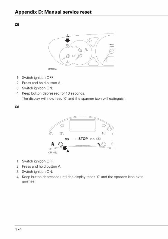
Appendix D: Manual service reset
174
C5
1. Switch ignition OFF.2. Press and hold button A.3. Switch ignition ON.4. Keep button depressed for 10 seconds.
The display will now read '0' and the spanner icon will extinguish.
C8
1. Switch ignition OFF.2. Press and hold button A.3. Switch ignition ON.4. Keep button depressed until the display reads '0' and the spanner icon extin-
guishes.
OM1050
A
OM1052 A
STOP
+/-
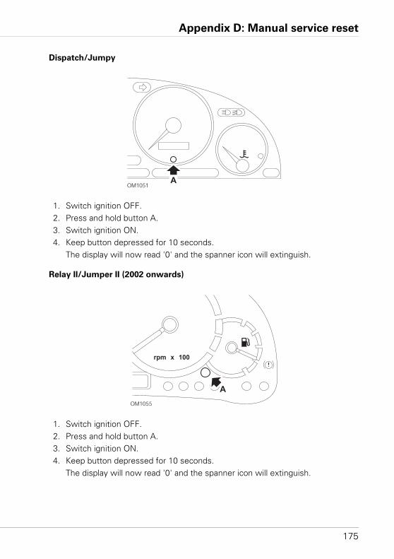
Appendix D: Manual service reset
175
Dispatch/Jumpy
1. Switch ignition OFF.2. Press and hold button A.3. Switch ignition ON.4. Keep button depressed for 10 seconds.
The display will now read '0' and the spanner icon will extinguish.
Relay II/Jumper II (2002 onwards)
1. Switch ignition OFF.2. Press and hold button A.3. Switch ignition ON.4. Keep button depressed for 10 seconds.
The display will now read '0' and the spanner icon will extinguish.
OM1051A
OM1055
A
rpm x 100
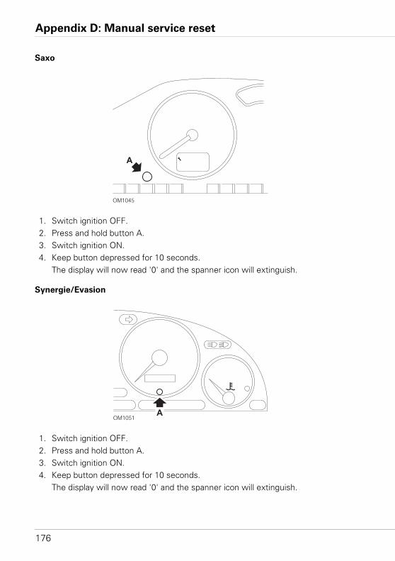
Appendix D: Manual service reset
176
Saxo
1. Switch ignition OFF.2. Press and hold button A.3. Switch ignition ON.4. Keep button depressed for 10 seconds.
The display will now read '0' and the spanner icon will extinguish.
Synergie/Evasion
1. Switch ignition OFF.2. Press and hold button A.3. Switch ignition ON.4. Keep button depressed for 10 seconds.
The display will now read '0' and the spanner icon will extinguish.
OM1045
A
OM1051A
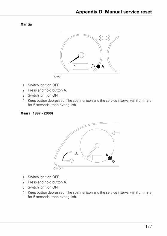
Appendix D: Manual service reset
177
Xantia
1. Switch ignition OFF.2. Press and hold button A.3. Switch ignition ON.4. Keep button depressed. The spanner icon and the service interval will illuminate
for 5 seconds, then extinguish.
Xsara (1997 - 2000)
1. Switch ignition OFF.2. Press and hold button A.3. Switch ignition ON.4. Keep button depressed. The spanner icon and the service interval will illuminate
for 5 seconds, then extinguish.
47673
A
OM1047
A
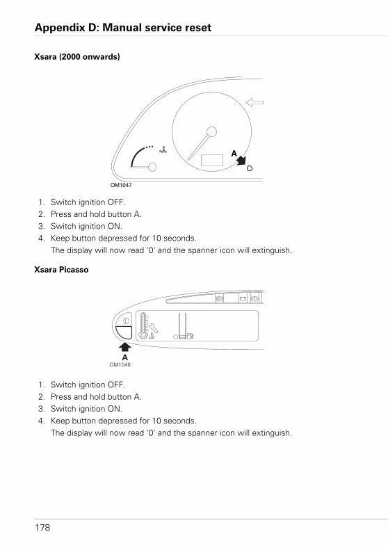
Appendix D: Manual service reset
178
Xsara (2000 onwards)
1. Switch ignition OFF.2. Press and hold button A.3. Switch ignition ON.4. Keep button depressed for 10 seconds.
The display will now read '0' and the spanner icon will extinguish.
Xsara Picasso
1. Switch ignition OFF.2. Press and hold button A.3. Switch ignition ON.4. Keep button depressed for 10 seconds.
The display will now read '0' and the spanner icon will extinguish.
OM1047
A
OM1048A
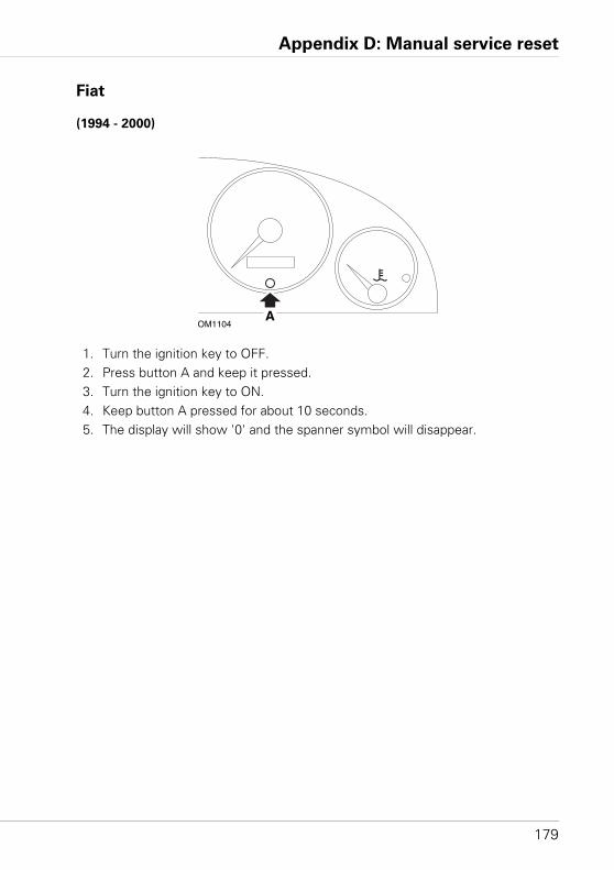
Appendix D: Manual service reset
179
Fiat
(1994 - 2000)
1. Turn the ignition key to OFF.2. Press button A and keep it pressed.3. Turn the ignition key to ON. 4. Keep button A pressed for about 10 seconds. 5. The display will show '0' and the spanner symbol will disappear.
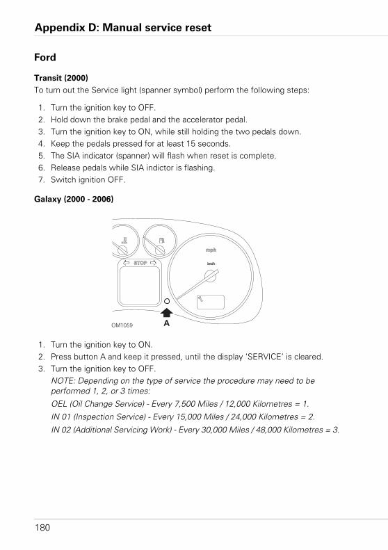
Appendix D: Manual service reset
180
Ford
Transit (2000)
To turn out the Service light (spanner symbol) perform the following steps:
1. Turn the ignition key to OFF.2. Hold down the brake pedal and the accelerator pedal.3. Turn the ignition key to ON, while still holding the two pedals down. 4. Keep the pedals pressed for at least 15 seconds. 5. The SIA indicator (spanner) will flash when reset is complete. 6. Release pedals while SIA indictor is flashing. 7. Switch ignition OFF.
Galaxy (2000 - 2006)
1. Turn the ignition key to ON.2. Press button A and keep it pressed, until the display ‘SERVICE’ is cleared.3. Turn the ignition key to OFF.
NOTE: Depending on the type of service the procedure may need to be performed 1, 2, or 3 times:
OEL (Oil Change Service) - Every 7,500 Miles / 12,000 Kilometres = 1.
IN 01 (Inspection Service) - Every 15,000 Miles / 24,000 Kilometres = 2.
IN 02 (Additional Servicing Work) - Every 30,000 Miles / 48,000 Kilometres = 3.
OM1059
STOP
mph
km/h
A
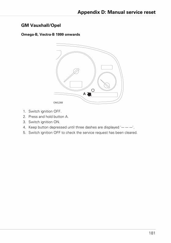
Appendix D: Manual service reset
181
GM Vauxhall/Opel
Omega-B, Vectra-B 1999 onwards
1. Switch ignition OFF.2. Press and hold button A.3. Switch ignition ON.4. Keep button depressed until three dashes are displayed '--- --- ---'.5. Switch ignition OFF to check the service request has been cleared.
OM1268
A
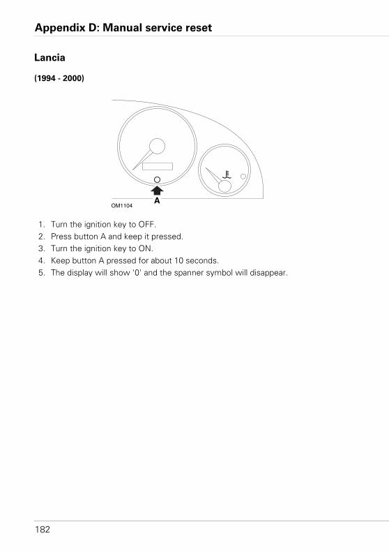
Appendix D: Manual service reset
182
Lancia
(1994 - 2000)
1. Turn the ignition key to OFF.2. Press button A and keep it pressed.3. Turn the ignition key to ON. 4. Keep button A pressed for about 10 seconds. 5. The display will show '0' and the spanner symbol will disappear.
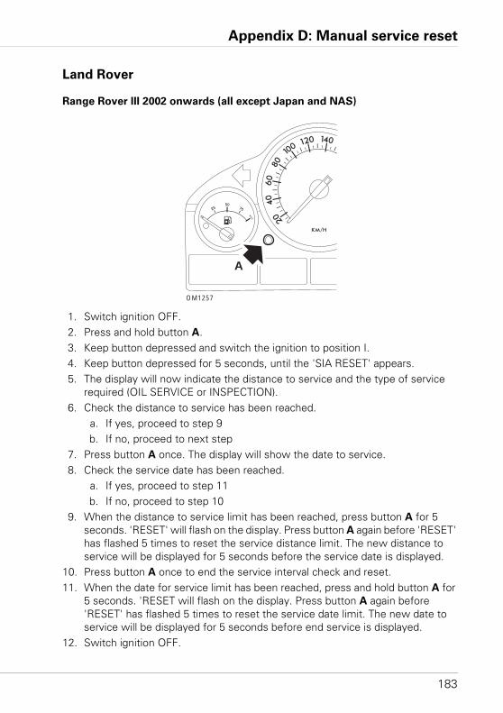
Appendix D: Manual service reset
183
Land Rover
Range Rover III 2002 onwards (all except Japan and NAS)
1. Switch ignition OFF. 2. Press and hold button A.3. Keep button depressed and switch the ignition to position I.4. Keep button depressed for 5 seconds, until the 'SIA RESET' appears.5. The display will now indicate the distance to service and the type of service
required (OIL SERVICE or INSPECTION).6. Check the distance to service has been reached.
a. If yes, proceed to step 9b. If no, proceed to next step
7. Press button A once. The display will show the date to service.8. Check the service date has been reached.
a. If yes, proceed to step 11b. If no, proceed to step 10
9. When the distance to service limit has been reached, press button A for 5 seconds. 'RESET' will flash on the display. Press button A again before 'RESET' has flashed 5 times to reset the service distance limit. The new distance to service will be displayed for 5 seconds before the service date is displayed.
10. Press button A once to end the service interval check and reset.11. When the date for service limit has been reached, press and hold button A for
5 seconds. 'RESET will flash on the display. Press button A again before 'RESET' has flashed 5 times to reset the service date limit. The new date to service will be displayed for 5 seconds before end service is displayed.
12. Switch ignition OFF.
OM1257
A
Appendix D: Manual service reset
184
Mercedes
Mercedes (1998 - 2007)
With the Flexible Service System and multi-function steering wheel controls
1. Switch ignition ON. 2. Use buttons and to scroll through the multi-function display until
the trip odometer and main odometer readings are displayed, or in the case of a separate main odometer display, scroll until the exterior temperature is displayed.
3. Use buttons and to scroll through the multifunction display until the service indicator or is displayed.
4. Press and hold button on the instrument cluster for approximately 3 seconds, until the following question is displayed within the multifunction display:‘DO YOU WANT TO RESET SERVICE INTERVAL? CONFIRM BY PRESSING R’or‘SERVICE INTERVAL? RESET WITH R BUTTON FOR 3 SEC’
5. Press and hold button on the instrument cluster again, until a signal sounds.6. The new service interval will appear in the multifunction display.
NOTE: The refers to the trip distance reset button.
Mercedes (1998 - 2002)
With the Flexible Service System and without multi-function steering wheel
controls
1. Turn the ignition switch to the ON position and then immediately press the button next to the digital display twice within one second. The current status for days or distance will be displayed.
2. Turn the ignition switch to the OFF position within 10 seconds.3. Press and hold the button while turning the ignition switch to the ON position.
The status for days or distance will be displayed again. 4. After approximately 10 seconds you will hear a confirmation chime and the
display will show ‘10,000 miles’ (‘15,000 km’). Release the button.
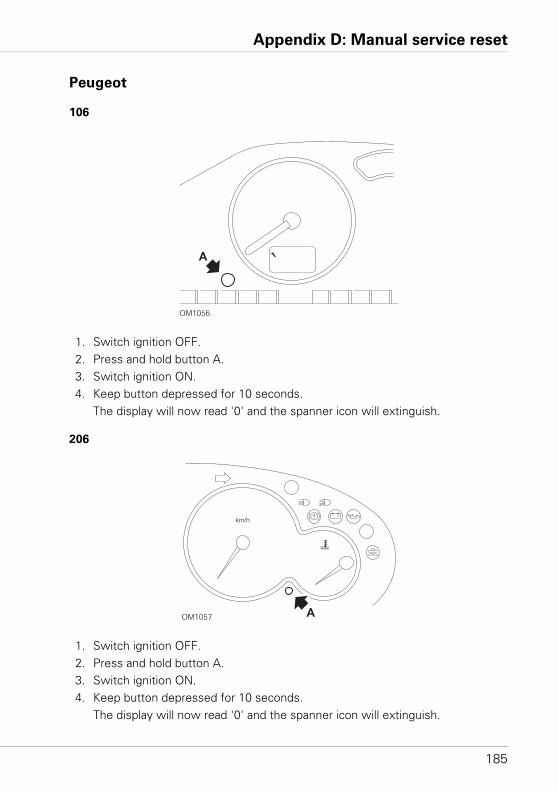
Appendix D: Manual service reset
185
Peugeot
106
1. Switch ignition OFF.2. Press and hold button A.3. Switch ignition ON.4. Keep button depressed for 10 seconds.
The display will now read '0' and the spanner icon will extinguish.
206
1. Switch ignition OFF.2. Press and hold button A.3. Switch ignition ON.4. Keep button depressed for 10 seconds.
The display will now read '0' and the spanner icon will extinguish.
OM1056
A
OM1057 A
km/h
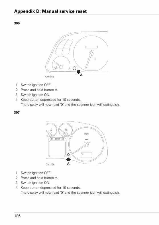
Appendix D: Manual service reset
186
306
1. Switch ignition OFF.2. Press and hold button A.3. Switch ignition ON.4. Keep button depressed for 10 seconds.
The display will now read '0' and the spanner icon will extinguish.
307
1. Switch ignition OFF.2. Press and hold button A.3. Switch ignition ON.4. Keep button depressed for 10 seconds.
The display will now read '0' and the spanner icon will extinguish.
OM1058A
OM1059
STOP
mph
km/h
A
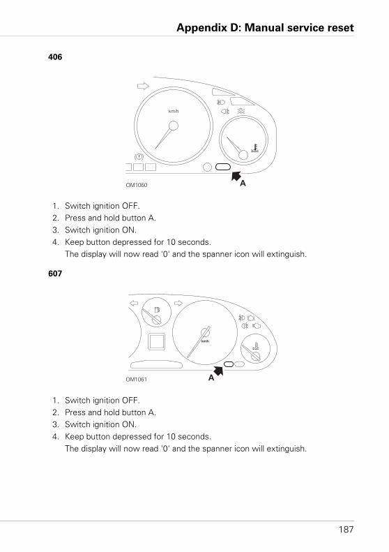
Appendix D: Manual service reset
187
406
1. Switch ignition OFF.2. Press and hold button A.3. Switch ignition ON.4. Keep button depressed for 10 seconds.
The display will now read '0' and the spanner icon will extinguish.
607
1. Switch ignition OFF.2. Press and hold button A.3. Switch ignition ON.4. Keep button depressed for 10 seconds.
The display will now read '0' and the spanner icon will extinguish.
OM1060
km/h
A
OM1061
km/h
A
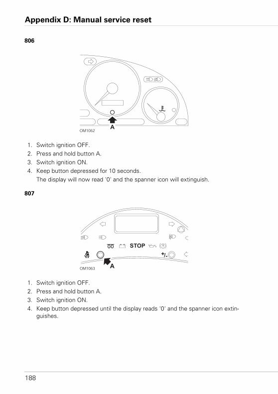
Appendix D: Manual service reset
188
806
1. Switch ignition OFF.2. Press and hold button A.3. Switch ignition ON.4. Keep button depressed for 10 seconds.
The display will now read '0' and the spanner icon will extinguish.
807
1. Switch ignition OFF.2. Press and hold button A.3. Switch ignition ON.4. Keep button depressed until the display reads '0' and the spanner icon extin-
guishes.
OM1062A
OM1063 A
STOP
+/-
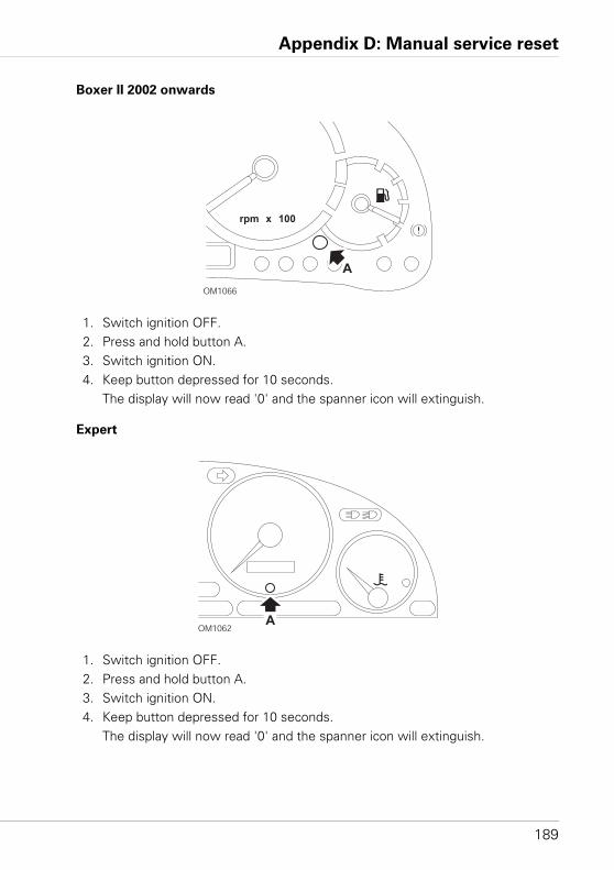
Appendix D: Manual service reset
189
Boxer II 2002 onwards
1. Switch ignition OFF.2. Press and hold button A.3. Switch ignition ON.4. Keep button depressed for 10 seconds.
The display will now read '0' and the spanner icon will extinguish.
Expert
1. Switch ignition OFF.2. Press and hold button A.3. Switch ignition ON.4. Keep button depressed for 10 seconds.
The display will now read '0' and the spanner icon will extinguish.
OM1066
A
rpm x 100
OM1062A
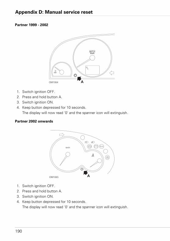
Appendix D: Manual service reset
190
Partner 1999 - 2002
1. Switch ignition OFF.2. Press and hold button A.3. Switch ignition ON.4. Keep button depressed for 10 seconds.
The display will now read '0' and the spanner icon will extinguish.
Partner 2002 onwards
1. Switch ignition OFF.2. Press and hold button A.3. Switch ignition ON.4. Keep button depressed for 10 seconds.
The display will now read '0' and the spanner icon will extinguish.
OM1064 A
km/hMPH
OM1065 A
km/h
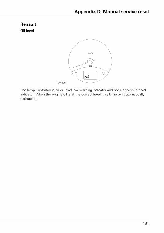
Appendix D: Manual service reset
191
Renault
Oil level
The lamp illustrated is an oil level low warning indicator and not a service interval indicator. When the engine oil is at the correct level, this lamp will automatically extinguish.
OM1067
km/h
km
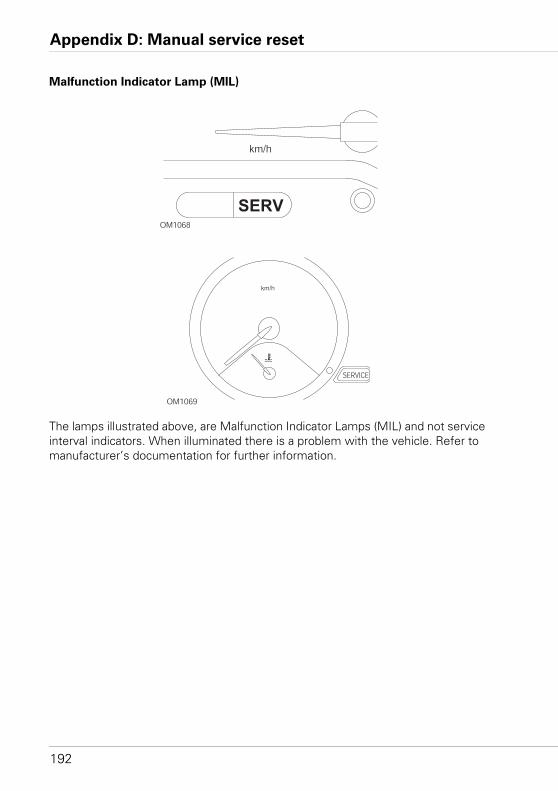
Appendix D: Manual service reset
192
Malfunction Indicator Lamp (MIL)
The lamps illustrated above, are Malfunction Indicator Lamps (MIL) and not service interval indicators. When illuminated there is a problem with the vehicle. Refer to manufacturer’s documentation for further information.
OM1068
km/h
SERV
OM1069
SERVICE
km/h
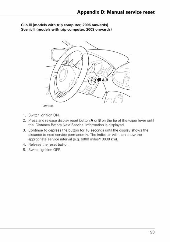
Appendix D: Manual service reset
193
Clio III (models with trip computer; 2006 onwards)
Scenic II (models with trip computer; 2003 onwards)
1. Switch ignition ON.2. Press and release display reset button A or B on the tip of the wiper lever until
the 'Distance Before Next Service’ information is displayed. 3. Continue to depress the button for 10 seconds until the display shows the
distance to next service permanently. The indicator will then show the appropriate service interval (e.g. 6000 miles/10000 km).
4. Release the reset button.5. Switch ignition OFF.
OM1384
A,B
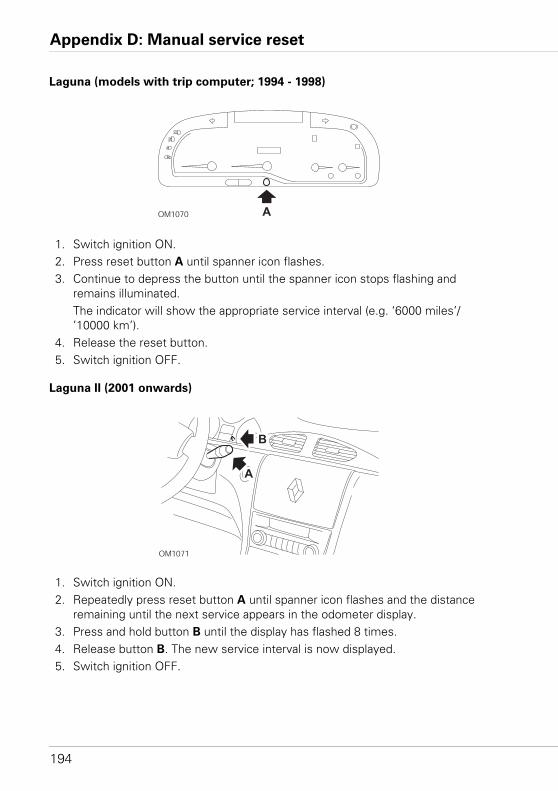
Appendix D: Manual service reset
194
Laguna (models with trip computer; 1994 - 1998)
1. Switch ignition ON.2. Press reset button A until spanner icon flashes.3. Continue to depress the button until the spanner icon stops flashing and
remains illuminated.The indicator will show the appropriate service interval (e.g. ‘6000 miles’/’10000 km’).
4. Release the reset button.5. Switch ignition OFF.
Laguna II (2001 onwards)
1. Switch ignition ON.2. Repeatedly press reset button A until spanner icon flashes and the distance
remaining until the next service appears in the odometer display.3. Press and hold button B until the display has flashed 8 times.4. Release button B. The new service interval is now displayed.5. Switch ignition OFF.
OM1070 A
OM1071
A
B
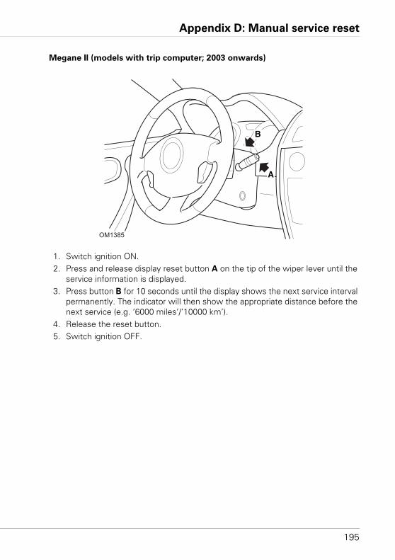
Appendix D: Manual service reset
195
Megane II (models with trip computer; 2003 onwards)
1. Switch ignition ON.2. Press and release display reset button A on the tip of the wiper lever until the
service information is displayed.3. Press button B for 10 seconds until the display shows the next service interval
permanently. The indicator will then show the appropriate distance before the next service (e.g. ‘6000 miles’/’10000 km’).
4. Release the reset button.5. Switch ignition OFF.
OM1385
A
B
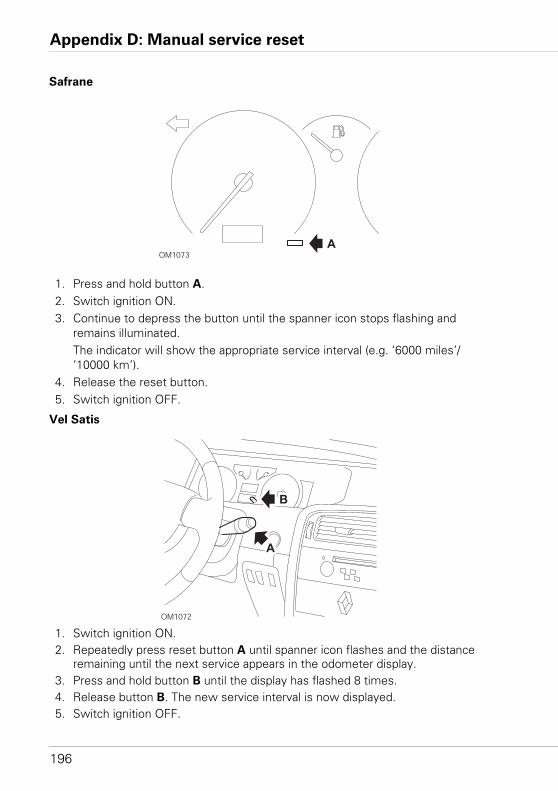
Appendix D: Manual service reset
196
Safrane
1. Press and hold button A.2. Switch ignition ON.3. Continue to depress the button until the spanner icon stops flashing and
remains illuminated.The indicator will show the appropriate service interval (e.g. ‘6000 miles’/’10000 km’).
4. Release the reset button.5. Switch ignition OFF.
Vel Satis
1. Switch ignition ON.2. Repeatedly press reset button A until spanner icon flashes and the distance
remaining until the next service appears in the odometer display.3. Press and hold button B until the display has flashed 8 times.4. Release button B. The new service interval is now displayed.5. Switch ignition OFF.
OM1073A
OM1072
A
B
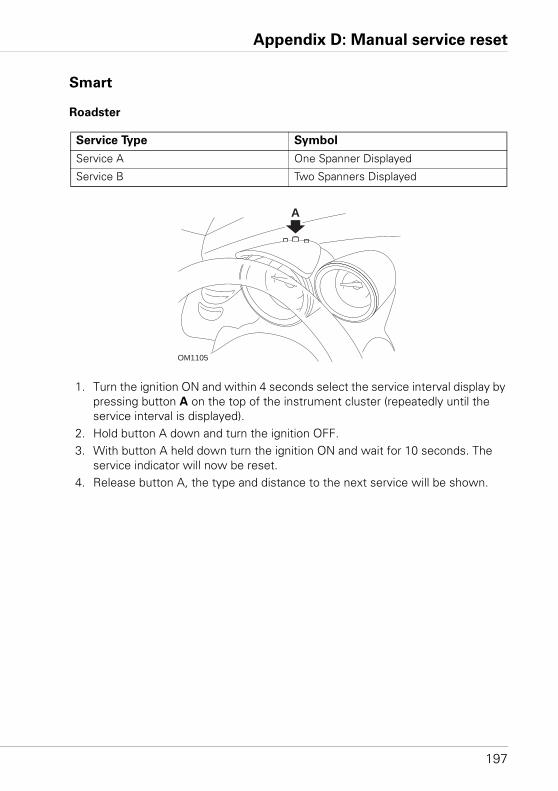
Appendix D: Manual service reset
197
Smart
Roadster
1. Turn the ignition ON and within 4 seconds select the service interval display by pressing button A on the top of the instrument cluster (repeatedly until the service interval is displayed).
2. Hold button A down and turn the ignition OFF.3. With button A held down turn the ignition ON and wait for 10 seconds. The
service indicator will now be reset. 4. Release button A, the type and distance to the next service will be shown.
Service Type Symbol
Service A One Spanner Displayed
Service B Two Spanners Displayed
A
OM1105
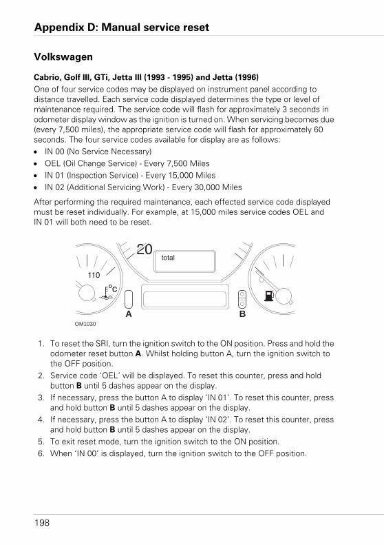
Appendix D: Manual service reset
198
Volkswagen
Cabrio, Golf III, GTi, Jetta III (1993 - 1995) and Jetta (1996)
One of four service codes may be displayed on instrument panel according to distance travelled. Each service code displayed determines the type or level of maintenance required. The service code will flash for approximately 3 seconds in odometer display window as the ignition is turned on. When servicing becomes due (every 7,500 miles), the appropriate service code will flash for approximately 60 seconds. The four service codes available for display are as follows:• IN 00 (No Service Necessary)• OEL (Oil Change Service) - Every 7,500 Miles• IN 01 (Inspection Service) - Every 15,000 Miles• IN 02 (Additional Servicing Work) - Every 30,000 Miles
After performing the required maintenance, each effected service code displayed must be reset individually. For example, at 15,000 miles service codes OEL and IN 01 will both need to be reset.
1. To reset the SRI, turn the ignition switch to the ON position. Press and hold the odometer reset button A. Whilst holding button A, turn the ignition switch to the OFF position.
2. Service code ‘OEL’ will be displayed. To reset this counter, press and hold button B until 5 dashes appear on the display.
3. If necessary, press the button A to display ‘IN 01’. To reset this counter, press and hold button B until 5 dashes appear on the display.
4. If necessary, press the button A to display ‘IN 02’. To reset this counter, press and hold button B until 5 dashes appear on the display.
5. To exit reset mode, turn the ignition switch to the ON position.6. When ‘IN 00’ is displayed, turn the ignition switch to the OFF position.
OM1030
A B
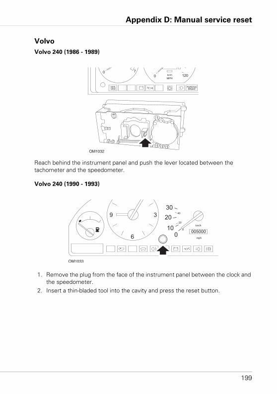
Appendix D: Manual service reset
199
Volvo
Volvo 240 (1986 - 1989)
Reach behind the instrument panel and push the lever located between the tachometer and the speedometer.
Volvo 240 (1990 - 1993)
1. Remove the plug from the face of the instrument panel between the clock and the speedometer.
2. Insert a thin-bladed tool into the cavity and press the reset button.
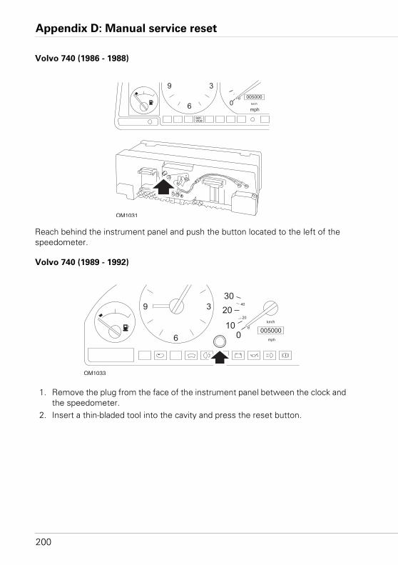
Appendix D: Manual service reset
200
Volvo 740 (1986 - 1988)
Reach behind the instrument panel and push the button located to the left of the speedometer.
Volvo 740 (1989 - 1992)
1. Remove the plug from the face of the instrument panel between the clock and the speedometer.
2. Insert a thin-bladed tool into the cavity and press the reset button.
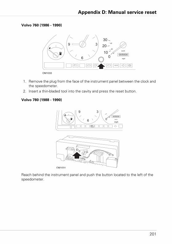
Appendix D: Manual service reset
201
Volvo 760 (1986 - 1990)
1. Remove the plug from the face of the instrument panel between the clock and the speedometer.
2. Insert a thin-bladed tool into the cavity and press the reset button.
Volvo 780 (1988 - 1990)
Reach behind the instrument panel and push the button located to the left of the speedometer.
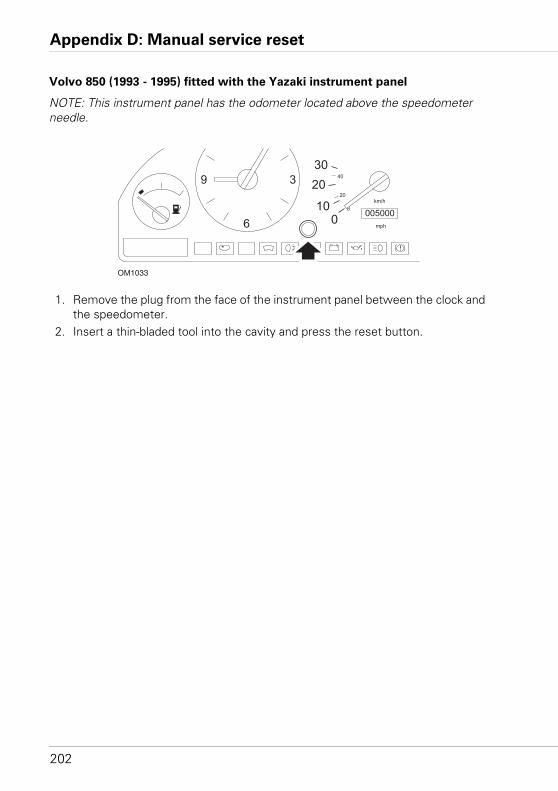
Appendix D: Manual service reset
202
Volvo 850 (1993 - 1995) fitted with the Yazaki instrument panel
NOTE: This instrument panel has the odometer located above the speedometer needle.
1. Remove the plug from the face of the instrument panel between the clock and the speedometer.
2. Insert a thin-bladed tool into the cavity and press the reset button.
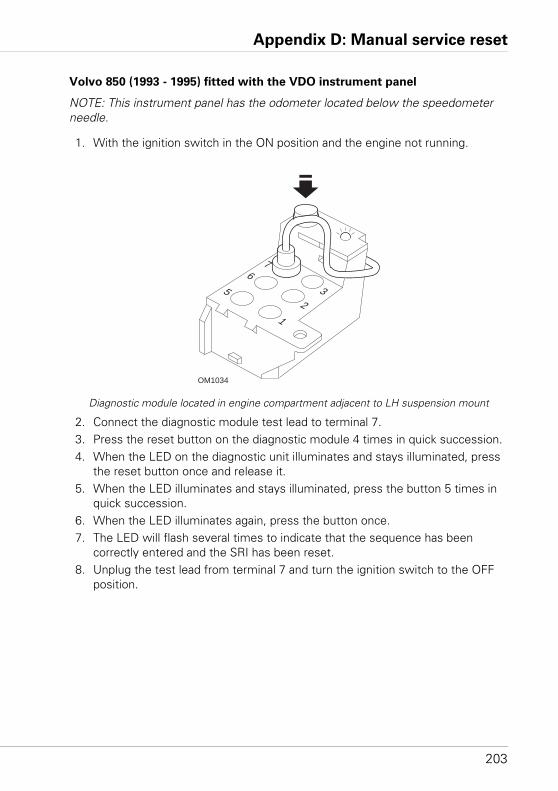
Appendix D: Manual service reset
203
Volvo 850 (1993 - 1995) fitted with the VDO instrument panel
NOTE: This instrument panel has the odometer located below the speedometer needle.
1. With the ignition switch in the ON position and the engine not running.
Diagnostic module located in engine compartment adjacent to LH suspension mount
2. Connect the diagnostic module test lead to terminal 7. 3. Press the reset button on the diagnostic module 4 times in quick succession.4. When the LED on the diagnostic unit illuminates and stays illuminated, press
the reset button once and release it. 5. When the LED illuminates and stays illuminated, press the button 5 times in
quick succession. 6. When the LED illuminates again, press the button once. 7. The LED will flash several times to indicate that the sequence has been
correctly entered and the SRI has been reset.8. Unplug the test lead from terminal 7 and turn the ignition switch to the OFF
position.
OM1034
12
356
7
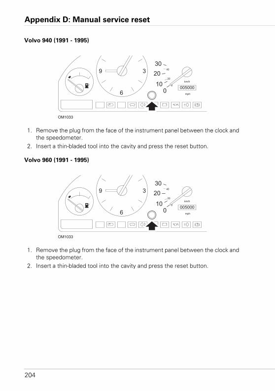
Appendix D: Manual service reset
204
Volvo 940 (1991 - 1995)
1. Remove the plug from the face of the instrument panel between the clock and the speedometer.
2. Insert a thin-bladed tool into the cavity and press the reset button.
Volvo 960 (1991 - 1995)
1. Remove the plug from the face of the instrument panel between the clock and the speedometer.
2. Insert a thin-bladed tool into the cavity and press the reset button.

www.trwaftermarket.com/easycheck