Embed Size (px)
Citation preview
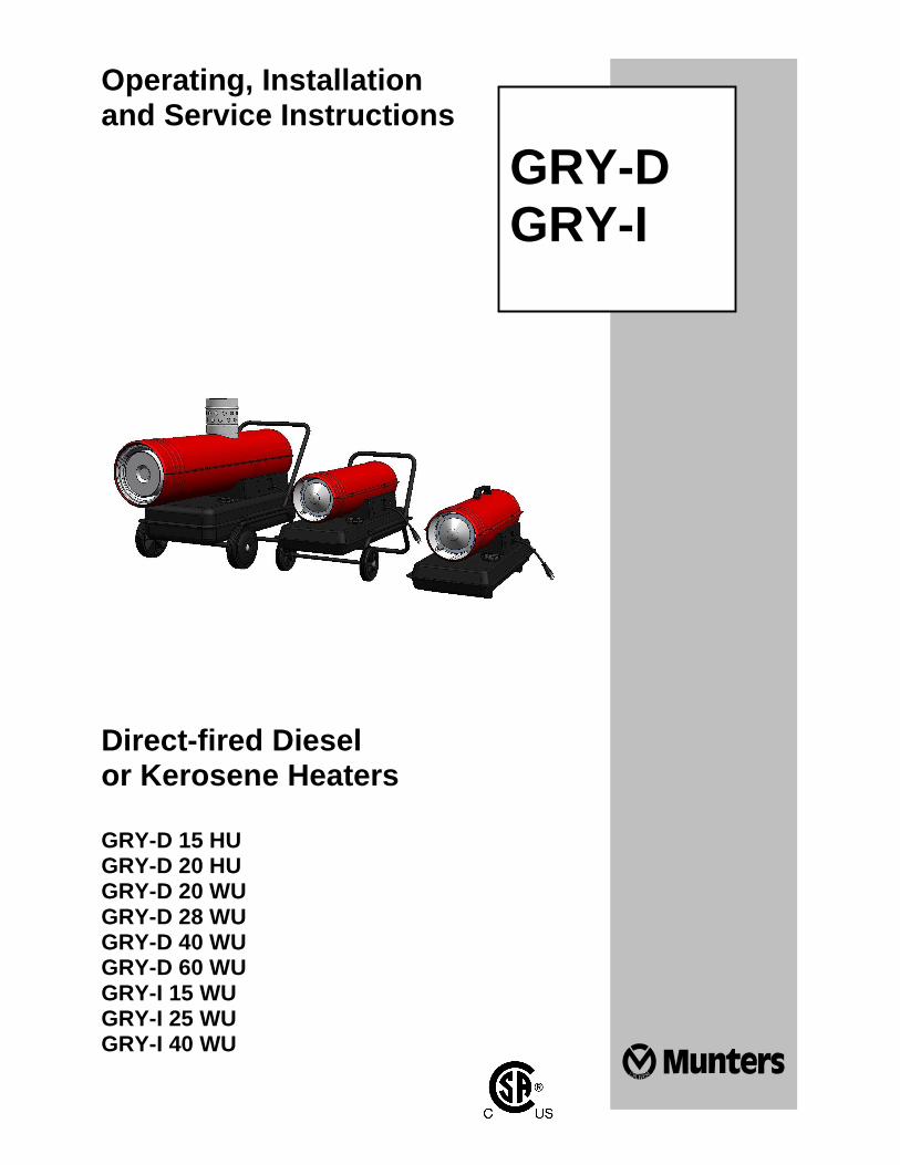
Operating, Installation and Service Instructions
Direct-fired Diesel or Kerosene Heaters GRY-D 15 HU GRY-D 20 HU GRY-D 20 WU GRY-D 28 WU GRY-D 40 WU GRY-D 60 WU GRY-I 15 WU GRY-I 25 WU GRY-I 40 WU
GRY-D GRY-I
__________________________________________________________________________________________________________ 2
Index 1. General safety rules 2. Description of the appliance 3. Technical data 4. Installation instructions 5. Instructions for use 6. Maintenance 7. Troubleshooting
__________________________________________________________________________________________________________ 3
1. GENERAL SAFETY RULES
• READ INSTRUCTIONS CAREFULLY. READ AND FOLLOW ALL INSTRUCTIONS. PLACE INSTRUCTIONS IN A SAFE PLACE FOR FUTURE REFERENCE. DO NOT ALLOW ANYONE WHO HAS NOT READ THESE INSTRUCTIONS TO ASSEMBLE, LIGHT, ADJUST OR OPERATE THE HEATER. • IF THE INFORMATION IN THIS MANUAL IS NOT FOLLOWED EXACTLY, A FIRE OR EXPLOSION MAY RESULT CAUSING PROPERTY DAMAGE, PERSONAL INJURY OR LOSS OF LIFE. • SERVICE MUST BE PERFORMED BY A QUALIFIED SERVICE AGENCY. • UNVENTED PORTABLE HEATERS USE AIR (OXYGEN) FROM THE AREA IN WHICH IT IS USED. ADEQUATE COMBUSTION AND VENTILATION AIR MUST BE PROVIDED. REFER TO INSTRUCTIONS.
WARNING DO NOT STORE OR USE GASOLINE OR OTHER FLAMMABLE VAPORS AND LIQUIDS IN THE VICINITY OF THIS OR ANY OTHER APPLIANCE.
WARNING FIRE, BURN, INHALATION, AND EXPLOSION HAZARD. KEEP SOLID COMBUSTIBLES, SUCH AS BUILDING MATERIALS, PAPER OR CARDBOARD, A SAFE DISTANCE AWAY FROM THE HEATER AS RECOMMENDED BY THE INSTRUCTIONS. NEVER USE THE HEATER IN SPACES WHICH DO OR MAY CONTAIN VOLATILE OR AIRBORNE COMBUSTIBLES, OR PRODUCTS SUCH AS GASOLINE, SOLVENTS, PAINT THINNER, DUST PARTICLES OR UNKNOWN CHEMICALS.
WARNING COMBUSTION BY-PRODUCTS PRODUCED WHEN USING THIS PRODUCT CONTAIN CARBON MONOXIDE, A CHEMICAL KNOWN TO THE STATE OF CALIFORNIA TO CAUSE CANCER AND BIRTH DEFECTS (OR OTHER REPRODUCTIVE HARM).
GENERAL HAZARD WARNING FAILURE TO COMPLY WITH THE PRECAUTIONS AND INSTRUCTIONS PROVIDED WITH THIS HEATER, CAN RESULT IN DEATH, SERIOUS BODILY INJURY AND PROPERTY LOSS OR DAMAGE FROM HAZARDS OF FIRE, EXPLOSION, BURN, ASPHYXIATION, CARBON MONOXIDE POISONING, AND/OR ELECTRICAL SHOCK. ONLY PERSONS WHO CAN UNDERSTAND AND FOLLOW THE INSTRUCTIONS SHOULD USE OR SERVICE THIS HEATER. IF YOU NEED ASSISTANCE OR HEATER INFORMATION SUCH AS AN INSTRUCTIONS MANUAL, LABELS, ETC. CONTACT THE MANUFACTURER.
WARNING NOT FOR HOME OR RECREATIONAL VEHICLE USE
WARNING YOUR SAFETY IS IMPORTANT TO YOU AND TO OTHERS, SO PLEASE READ THESE INSTRUCTIONS BEFORE YOU OPERATE THIS HEATER
• THE ELECTRICAL SYSTEM TO WHICH THE APPLIANCE IS CONNECTED MUST COMPLY WITH CURRENT LEGISLATION. INSTALLATION REQUIRES A SUITABLE CIRCUIT BREAKER IN THE MAIN DISTRIBUTION BOARD. • UNPLUG THE APPLIANCE BEFORE PERFORMING ANY MAINTENANCE OPERATIONS. • ALWAYS CHECK THE POWER CABLE BEFORE USING THE APPLIANCE. IT MUST NOT BE BENT, TAUT, STREACHED, CRUSHED OR ANY WAY DAMAGED. • THE POWER CABLE CONNECTION MUST BE MADE BY QUALIFIED PERSONNEL ONLY. USE AN ORIGINAL POWER CABLE ONLY WITH A 3-PIN APPROVED PLUG. • DANGER (BURNS)! DO NOT TOUCH THE EXHAUST GAS OUTLET. 2. APPLIANCE DESCRIPTION • Mobile space heater with:
� closed combustion chamber and gas exhaust duct (indirect-fired models) � open combustion chamber (direct-fired models)
__________________________________________________________________________________________________________ 4
� automatic cooling function (indirect-fired models and GRY-D 60)
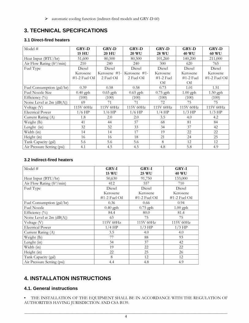
3. TECHNICAL SPECIFICATIONS 3.1 Direct-fired heaters Model # GRY-D
15 HU GRY-D 20 HU
GRY-D 20 WU
GRY-D 28 WU
GRY-D 40 WU
GRY-D 60 WU
Heat Input (BTU/hr) 51,600 80,500 80,500 101,260 140,200 211,000 Air Flow Rating (ft³/min) 210 240 240 300 620 765 Fuel Type Diesel
Kerosene #1-2 Fuel Oil
Diesel Kerosene #1-2 Fuel Oil
Diesel Kerosene #1-2 Fuel Oil
Diesel Kerosene #1-2 Fuel
Oil
Diesel Kerosene #1-2 Fuel
Oil
Diesel Kerosene
#1-2 Fuel Oil
Fuel Consumption (gal/hr) 0.39 0.58 0.58 0.73 1.01 1.51 Fuel Nozzle Size 0.40 gph 0.65 gph 0.65 gph 0.75 gph 1.00 gph 1.50 gph Efficiency (%) (100) (100) (100) (100) (100) (100) Noise Level at 2m (dB(A)) 69 71 71 72 75 75 Voltage (V) 115V 60Hz 115V 60Hz 115V 60Hz 115V 60Hz 115V 60Hz 115V 60Hz Electrical Power 1/6 HP 1/6 HP 1/6 HP 1/4 HP 1/3 HP 1/3 HP Current Rating (A) 1.8 2.0 2.0 3.5 4.0 4.2 Weight (lb) 41 44 57 68 81 84 Lenght (in) 32 32 33 34 37 42 Width (in) 14 14 17 19 22 22 Height (in) 16 16 18 21 24 25 Tank Capacity (gal) 5.6 5.6 5.6 8 12 12 Air Pressure Setting (psi) 4.1 4.5 4.5 4.8 5.8 4.9
3.2 Indirect-fired heaters Model # GRY-I
15 WU GRY-I 25 WU
GRY-I 40 WU
Heat Input (BTU/hr) 50,630 91,750 133,000 Air Flow Rating (ft³/min) 412 557 710 Fuel Type Diesel
Kerosene #1-2 Fuel Oil
Diesel Kerosene
#1-2 Fuel Oil
Diesel Kerosene
#1-2 Fuel Oil Fuel Consumption (gal/hr) 0.36 0.66 0.94 Fuel Nozzle 0.40 gph 0.75 gph 1.00 gph Efficiency (%) 84.4 80.0 81.4 Noise Level at 2m (dB(A)) 63 75 75 Voltage (V) 115V 60Hz 115V 60Hz 115V 60Hz Electrical Power 1/4 HP 1/3 HP 1/3 HP Current Rating (A) 3.5 4.0 4.0 Weight (lb) 77 88 93 Lenght (in) 34 37 42 Width (in) 19 22 22 Height (in) 22 25 26 Tank Capacity (gal) 8 12 12 Air Pressure Setting (psi) 4.4 4.8 4.9
4. INSTALLATION INSTRUCTIONS 4.1. General instructions
• THE INSTALLATION OF THE EQUIPMENT SHALL BE IN ACCORDANCE WITH THE REGULATION OF AUTHORITIES HAVING JURISDICTION AND CSA B139.
__________________________________________________________________________________________________________ 5
• The heater must be operated only by properly trained personnel. The manufacturer’s instructions must be followed.
• The heater must be installed and operated so that people are not exposed to dangers deriving from exhaust gases, from the hot air flow and in such a way that no fire risks exist.
• It is forbidden to install the heater in the surroundings of flammable materials, combustible products, or in explosive atmosphere.
• When an indirect-fired heater connected to a flue pipe is used in a closed room, provide a minimum opening area of 1 ft³ per US gallon capacity at the unit level.
• When a direct-fired heater - or an indirect-fired heater not connected to a flue pipe - is used in a closed room, provide a minimum opening area of 3 ft2 per US gallon capacity at the unit level and a continuous, natural air circulation through windows and doors. For the use of the heater the general and special fire safety regulations in force in all fields of applications must be followed. In any case the following minimum safety clearances from materials or objects in the surroundings of the heater must be assured: Side: 2 ft (610 mm) Air inlet side: 2 ft (610 mm) Top: 5 ft (1525 mm) Hot air outlet side: 10 ft (3050 mm) Floor: 0 ft (0 mm) Flue pipe: 3 ft (915 mm)
• Floors and ceilings must be made of fireproof materials in the place where the heater is operated.
• The air inlet and outlet must never be blocked for any reason.
• Install the heater on a flat, level floor in a steady position.
• It is forbidden to connect direct-fired heaters to air ducts.
4.2 Maintenance and checks • Depending on the operational conditions, usually every year, the heater should be checked by qualified personnel. Prior to start-up, the user must check for any evident non-compliance with rules of use, safety and protection.
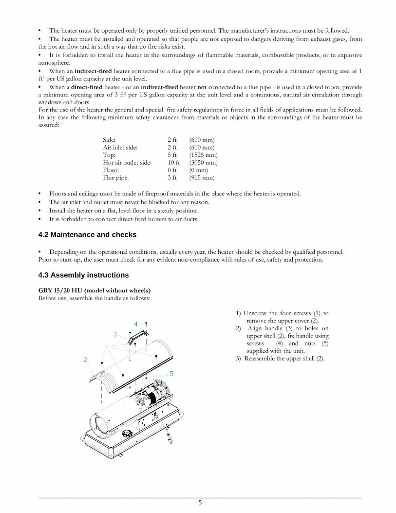
4.3 Assembly instructions GRY 15/20 HU (model without wheels) Before use, assemble the handle as follows:
1
4
5
3
2
1) Unscrew the four screws (1) to remove the upper cover (2).
2) Align handle (3) to holes on upper shell (2), fix handle using screws (4) and nuts (5) supplied with the unit.
3) Reassemble the upper shell (2).
__________________________________________________________________________________________________________ 6
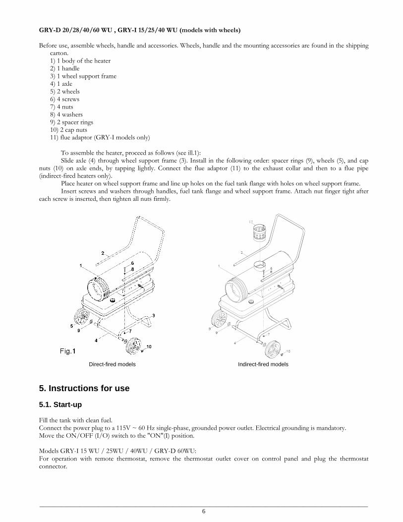
GRY-D 20/28/40/60 WU , GRY-I 15/25/40 WU (models with wheels) Before use, assemble wheels, handle and accessories. Wheels, handle and the mounting accessories are found in the shipping
carton. 1) 1 body of the heater 2) 1 handle 3) 1 wheel support frame 4) 1 axle 5) 2 wheels 6) 4 screws 7) 4 nuts 8) 4 washers 9) 2 spacer rings 10) 2 cap nuts 11) flue adaptor (GRY-I models only) To assemble the heater, proceed as follows (see ill.1): Slide axle (4) through wheel support frame (3). Install in the following order: spacer rings (9), wheels (5), and cap nuts (10) on axle ends, by tapping lightly. Connect the flue adaptor (11) to the exhaust collar and then to a flue pipe (indirect-fired heaters only). Place heater on wheel support frame and line up holes on the fuel tank flange with holes on wheel support frame. Insert screws and washers through handles, fuel tank flange and wheel support frame. Attach nut finger tight after each screw is inserted, then tighten all nuts firmly.
Direct-fired models Indirect-fired models
5. Instructions for use 5.1. Start-up Fill the tank with clean fuel. Connect the power plug to a 115V ~ 60 Hz single-phase, grounded power outlet. Electrical grounding is mandatory. Move the ON/OFF (I/O) switch to the "ON"(I) position. Models GRY-I 15 WU / 25WU / 40WU / GRY-D 60WU: For operation with remote thermostat, remove the thermostat outlet cover on control panel and plug the thermostat connector.
__________________________________________________________________________________________________________ 7
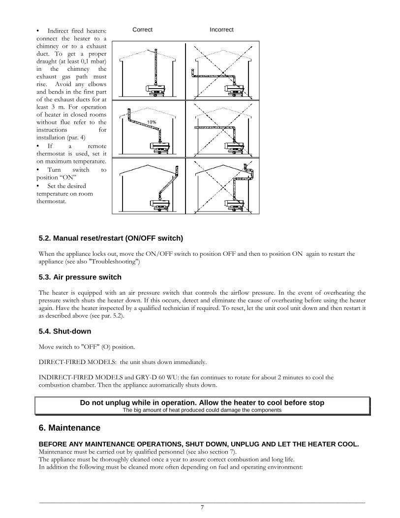
• Indirect fired heaters: connect the heater to a chimney or to a exhaust duct. To get a proper draught (at least 0,1 mbar) in the chimney the exhaust gas path must rise. Avoid any elbows and bends in the first part of the exhaust ducts for at least 3 m. For operation of heater in closed rooms without flue refer to the instructions for installation (par. 4)
• If a remote thermostat is used, set it on maximum temperature.
• Turn switch to position “ON”
• Set the desired temperature on room thermostat.
Correct Incorrect
5.2. Manual reset/restart (ON/OFF switch) When the appliance locks out, move the ON/OFF switch to position OFF and then to position ON again to restart the appliance (see also "Troubleshooting")
5.3. Air pressure switch The heater is equipped with an air pressure switch that controls the airflow pressure. In the event of overheating the pressure switch shuts the heater down. If this occurs, detect and eliminate the cause of overheating before using the heater again. Have the heater inspected by a qualified technician if required. To reset, let the unit cool unit down and then restart it as described above (see par. 5.2).
5.4. Shut-down Move switch to "OFF" (O) position. DIRECT-FIRED MODELS: the unit shuts down immediately. INDIRECT-FIRED MODELS and GRY-D 60 WU: the fan continues to rotate for about 2 minutes to cool the combustion chamber. Then the appliance automatically shuts down.
Do not unplug while in operation. Allow the heater to cool before stop The big amount of heat produced could damage the components
6. Maintenance BEFORE ANY MAINTENANCE OPERATIONS, SHUT DOWN, UNPLUG AND LET THE HEATER COOL. Maintenance must be carried out by qualified personnel (see also section 7). The appliance must be thoroughly cleaned once a year to assure correct combustion and long life. In addition the following must be cleaned more often depending on fuel and operating environment:
__________________________________________________________________________________________________________ 8
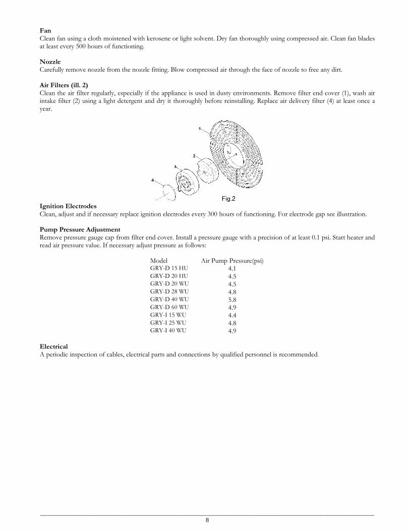
Fan Clean fan using a cloth moistened with kerosene or light solvent. Dry fan thoroughly using compressed air. Clean fan blades at least every 500 hours of functioning. Nozzle Carefully remove nozzle from the nozzle fitting. Blow compressed air through the face of nozzle to free any dirt. Air Filters (ill. 2) Clean the air filter regularly, especially if the appliance is used in dusty environments. Remove filter end cover (1), wash air intake filter (2) using a light detergent and dry it thoroughly before reinstalling. Replace air delivery filter (4) at least once a year.
Ignition Electrodes Clean, adjust and if necessary replace ignition electrodes every 300 hours of functioning. For electrode gap see illustration. Pump Pressure Adjustment Remove pressure gauge cap from filter end cover. Install a pressure gauge with a precision of at least 0.1 psi. Start heater and read air pressure value. If necessary adjust pressure as follows:
Model Air Pump Pressure(psi) GRY-D 15 HU 4.1 GRY-D 20 HU 4.5 GRY-D 20 WU 4.5 GRY-D 28 WU 4.8 GRY-D 40 WU 5.8 GRY-D 60 WU 4.9 GRY-I 15 WU 4.4 GRY-I 25 WU 4.8 GRY-I 40 WU 4.9
Electrical A periodic inspection of cables, electrical parts and connections by qualified personnel is recommended.
__________________________________________________________________________________________________________ 9
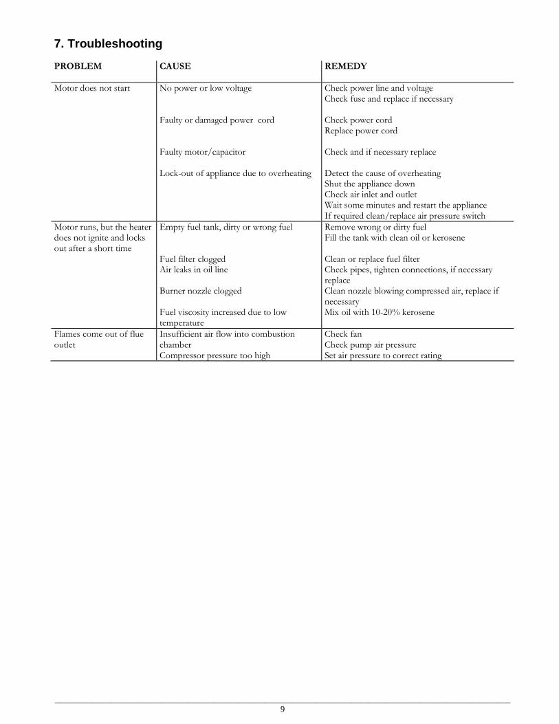
7. Troubleshooting PROBLEM
CAUSE REMEDY
Motor does not start
No power or low voltage Faulty or damaged power cord Faulty motor/capacitor Lock-out of appliance due to overheating
Check power line and voltage Check fuse and replace if necessary Check power cord Replace power cord Check and if necessary replace Detect the cause of overheating Shut the appliance down Check air inlet and outlet Wait some minutes and restart the appliance If required clean/replace air pressure switch
Motor runs, but the heater does not ignite and locks out after a short time
Empty fuel tank, dirty or wrong fuel Remove wrong or dirty fuel Fill the tank with clean oil or kerosene
Fuel filter clogged Clean or replace fuel filter Air leaks in oil line Check pipes, tighten connections, if necessary
replace Burner nozzle clogged Clean nozzle blowing compressed air, replace if
necessary Fuel viscosity increased due to low
temperature Mix oil with 10-20% kerosene
Flames come out of flue outlet
Insufficient air flow into combustion chamber Compressor pressure too high
Check fan Check pump air pressure Set air pressure to correct rating
__________________________________________________________________________________________________________ 10
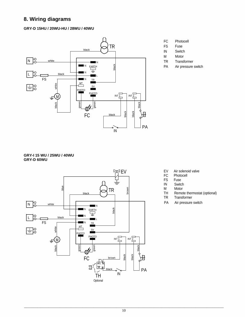
8. Wiring diagrams GRY-D 15HU / 20WU-HU / 28WU / 40WU
L
N
TR
blac
k
black
FS
white
whi
tebl
ack
M
blac
k
EARTH
TR
SV
PHOTOPHOTO
MT
INT 1
black
blac
k
IN
INT 2
P
PA
FC blac
k
NN
LN
N
black
gree
n
gree
n
FC PhotocellFS FuseIN SwitchM MotorTR TransformerPA Air pressure switch
GRY-I 15 WU / 25WU / 40WU GRY-D 60WU
blue
brow
n
L
N
TR
blac
k
black
FS
white
whi
tebl
ack
M
blac
k
EARTH
TR
SV
PHOTOPHOTO
MT
INT 1
black
blac
k
IN
INT 2
P
PA
FC blac
k
NN
LN
N
black
EV
Optional
2
3 1
TH
gree
n
gre
en
brown
TR Transformer
FS
TH
INM
EVFC
Air solenoid valve
Remote thermostat (optional)
FuseSwitchMotor
Photocell
PA Air pressure switch

__________________________________________________________________________________________________________ 11
__________________________________________________________________________________________________________ 12