Embed Size (px)
Citation preview

HT380 Direct Fired Heater
MoffittCorp.com | (800) 474-3267 1351 13th Ave S. Suite 130 Jacksonville Beach, FL 32250

HT380 Direct Fired Natural Warming
MoffittCorp.com
Page 1 of 41
(800) 474-3267
HT380 Direct Fire Heater Table of Contents HT380 Direct Fired Heaters Product Details ................................................................................................. 2
HT380 Single Blower Models- Sizes 109 & 130 Horizontal Arrangement..................................................... 3
HT380 Single Blower Models - Sizes 109 & 130 Horizontal Arrangement Dimensional Data ...................... 4
HT380 Twin Blower Models- Sizes 215-230 Horizontal Arrangement .......................................................... 5
HT380 Twin Blower Models - Sizes 215-230 Horizontal Arrangement Dimensional Data ........................... 6
HT380 Twin Blower Models- Sizes 233 & 240 Horizontal Arrangement ...................................................... 7
HT380 Twin Blower Models - Sizes 233 & 240 Horizontal Arrangement Dimensional Data ........................ 8
HT380 Roof Curbs for 100% Make-Up Air Units ........................................................................................... 9
HT380 Roof Curbs - Cooling Information .................................................................................................... 10
Roof Curbs for Base Units with Return Air, after Burner ............................................................................ 11
Roof Curbs for Base Units with Return Air, after Burner cont. ................................................................... 12
Roof Curbs for Base Units with Return Air, before Burner ......................................................................... 13
Roof Curbs for Base Units with Return Air, before Burner cont. ................................................................ 14
HT380 Series Vertical Models- Sizes 109-130 ............................................................................................. 15
HT380 Series Vertical Models- Sizes 109-130 Dimensional Data ............................................................... 16
HT380 Series Vertical Models- Sizes 215-230 ............................................................................................. 17
HT380 Series Vertical Models- Sizes 215-230 Dimensional Data ............................................................... 18
HT380 Series Vertical Models - Sizes 233 & 240 ......................................................................................... 19
HT380 Approximate Unit Weights (lbs) ...................................................................................................... 20
HT380 Series Dampers ................................................................................................................................ 21
HT380 Series Discharge Louvers ................................................................................................................. 21
HT380 Series Filter and V-Bank Filter Information ..................................................................................... 22
HT380 Series Mixing Box Information ........................................................................................................ 23
HT380 Series Intake Hoods and Filter Information ..................................................................................... 24
HT380 Direct Fire Heaters- Single Blower Models Information.................................................................. 25
HT380 Direct Fire Heaters - Single Blower Models Selection Chart ........................................................... 26
HT380 Direct Fire Heaters - Twin Blower Models Selection Chart ............................................................. 27
HT380 Twin Blower Models- Burner Performance Table ........................................................................... 28
HT380 Twin Blower Models - Burner Performance Table cont. ................................................................. 29
HT380 Twin Blower Models - Burner Performance Table .......................................................................... 30
HT380 Twin Blower Models - Burner Performance Table cont. ................................................................. 31
HT380 Series Gas Piping Layout .................................................................................................................. 32
HT380 Series Gas Piping Layout cont. ......................................................................................................... 33
MDT Control System ................................................................................................................................... 34
MRT Control System ................................................................................................................................... 35
MRT Pro Control System ............................................................................................................................. 36
MRT Expert Control System ........................................................................................................................ 37
Typical Wiring Diagram - Model HT380- Page 1 ......................................................................................... 38
Typical Wiring Diagram - Model HT380- Page 2 ......................................................................................... 39
Typical Wiring Diagram - Model HT380- Page 3 ......................................................................................... 40
Typical Wiring Diagram - Model HT380- Page 4 ......................................................................................... 41

HT380 Direct Fired Natural Warming
MoffittCorp.com
Page 2 of 41
(800) 474-3267
HT380 Direct Fired Heaters Product Details
STANDARD FEATURES
CFM Range: 1,600 to 100,000
Burner range- 131,000 BTUH to 14 million
BTUH
Galvanized Steel Construction
DWDI centrifugal forward curved fans
TEFC or ODP motors
ETL burner
Hinged access door
Flame observation port
Pre-piped and tested burner assembly
Controls enclosure
OPTIONAL ACCESSORIES
Motorized inlet damper or discharge
damper
V-Bank filter box with filters
Inlet hood and bird screen with or without
filters
Insulation
Roof Curb (fan to discharge within unit
perimeter)
Extended grease lines
Vibration feet and hangars
Mild weather shutdown
Clogged filter switch
Disconnect switch
Painted Galvanized casing
Mixing box with filters and auto or manual
dampers
High pressure Regulator
UV flame detection
Circuit analyzer
Remote control panel
PRODUCT DESCRIPTION
The Moffitt Series HT380 Direct Fired Heaters are used to introduce high volumes of heated make-up air
into a building. Units are designed for outdoor or indoor mounting and can be provided in either
horizontal or vertical mounting arrangements. Units can be provided as 100% Make-up air units;
capture, reheat and return of building air (air desertification units); or a combination or both. All units
are ETL labeled.

HT380 Direct Fired Natural Warming
MoffittCorp.com
Page 3 of 41
(800) 474-3267
HT380 Single Blower Models- Sizes 109 & 130 Horizontal Arrangement
Unit Components
1. Centrifugal supply fan
2. Fan motor
3. Line Burner
4. Control Cabinet
5. Hinged control cabinet
access door
6. Observations Port
7. Access Door
8. Access Door (piping
compartment)
9. Lifting Lug
10. Unit Base
11. Manifold compartment
12. Airflow station (required
for ETL listed Return Air
Unit)
All specifications are subject to change without notice unless approved in submittal by Moffitt Corporation, Inc.

HT380 Direct Fired Natural Warming
MoffittCorp.com
Page 4 of 41
(800) 474-3267
HT380 Single Blower Models - Sizes 109 & 130 Horizontal Arrangement
Dimensional Data
All specifications are subject to change without notice unless approved in submittal by Moffitt Corporation, Inc.

HT380 Direct Fired Natural Warming
MoffittCorp.com
Page 5 of 41
(800) 474-3267
HT380 Twin Blower Models- Sizes 215-230 Horizontal Arrangement
Unit Components
1. Centrifugal supply fan
2. Fan motor
3. Line Burner
4. Control Cabinet
5. Hinged control cabinet
access door
6. Observations Port
7. Access Door
8. Access Door (piping
compartment)
9. Lifting Lug
10. Unit Base
11. Manifold compartment
12. Airflow station (required
for ETL listed Return Air
Unit)
All specifications are subject to change without notice unless approved in submittal by Moffitt Corporation, Inc.

HT380 Direct Fired Natural Warming
MoffittCorp.com
Page 6 of 41
(800) 474-3267
HT380 Twin Blower Models - Sizes 215-230 Horizontal Arrangement
Dimensional Data
All specifications are subject to change without notice unless approved in submittal by Moffitt Corporation, Inc.

HT380 Direct Fired Natural Warming
MoffittCorp.com
Page 7 of 41
(800) 474-3267
HT380 Twin Blower Models- Sizes 233 & 240 Horizontal Arrangement
Unit Components
1. Centrifugal supply fan
2. Fan motor
3. Line Burner
4. Control Cabinet
5. Hinged control cabinet
access door
6. Observations Port
7. Access Door
8. Access Door (piping
compartment)
9. Lifting Lug
10. Unit Base
11. Manifold compartment
12. Airflow station (required
for ETL listed Return Air
Unit
All specifications are subject to change without notice unless approved in submittal by Moffitt Corporation, Inc.

HT380 Direct Fired Natural Warming
MoffittCorp.com
Page 8 of 41
(800) 474-3267
HT380 Twin Blower Models - Sizes 233 & 240 Horizontal Arrangement
Dimensional Data
All specifications are subject to change without notice unless approved in submittal by Moffitt Corporation, Inc.

HT380 Direct Fired Natural Warming
MoffittCorp.com
Page 9 of 41
(800) 474-3267
HT380 Roof Curbs for 100% Make-Up Air Units
NOTES:
1. All dimensions in inches subject to
manufacturing tolerances.
2. Curb to be shipped loose and field
assembled.
3. Curb must be installed square and
level.
4. Curb requires intermediate structural
support and is not to be corner post
mounted.
5. Gaskets to be shipped with unit.
6. Bolting accessories shipped with
curb.
7. Curb drawings shown are for units
which have controls on the
“standard” side.
8. Available on horizontal units only.
All specifications are subject to change without notice unless approved in submittal by Moffitt Corporation, Inc.

HT380 Direct Fired Natural Warming
MoffittCorp.com
Page 10 of 41
(800) 474-3267
HT380 Roof Curbs - Cooling Information
Model Without Cooling
A B C D E L W 109 12 3⁄8 10 3⁄8 22 13⁄16 11 15⁄16 N/A 71 1⁄2 46 1⁄2 112 10 13⁄16 13 9⁄16 20 13⁄16 15 15⁄16 N/A 71 1⁄2 46 1⁄2 115 9 5⁄8 16 19 3⁄16 18 15⁄16 N/A 71 1⁄2 46 1⁄2 118 9 5⁄8 19 19 5⁄16 22 1⁄16 N/A 71 1⁄2 46 1⁄2 120 10 7⁄16 24 7⁄8 37 13⁄16 25 1⁄16 N/A 90 1⁄2 72 1⁄2 122 10 7⁄16 27 3⁄8 35 5⁄16 27 9⁄16 N/A 90 1⁄2 72 1⁄2 125 14 13⁄16 31 3⁄8 41 3⁄8 31 1⁄2 N/A 90 1⁄2 85 1⁄2 130 14 13⁄16 36 7⁄8 35 7⁄8 37 N/A 90 1⁄2 85 1⁄2 215 9 5⁄8 16 23 1⁄4 60 1⁄8 18 15⁄16 71 1⁄2 88 1⁄2 218 9 5⁄8 19 23 1⁄4 60 1⁄8 22 1⁄16 71 1⁄2 88 1⁄2 220 10 7⁄16 24 7⁄8 35 1⁄8 79 3⁄4 25 1⁄16 90 1⁄2 124 1⁄2 222 10 7⁄16 27 3⁄8 35 1⁄8 79 3⁄4 27 9⁄16 90 1⁄2 124 1⁄2 225 14 13⁄16 31 3⁄8 35 1⁄4 100 5⁄8 31 1⁄2 90 1⁄2 148 1⁄2 230 14 13⁄16 36 7⁄8 35 1⁄4 100 5⁄8 37 90 1⁄2 148 1⁄2 233 16 11⁄16 43 1⁄16 39 1⁄2 115 3⁄4 39 7⁄8 111 1⁄2 169 1⁄2 240 30 1⁄4 41 39 5⁄8 147 5⁄8 53 7⁄8 125 1⁄2 204 1⁄2
Model With Cooling A B C D L W X Y
109 3 1⁄4 18 3 1⁄4 40 153 1⁄2 46 1⁄2 76 1⁄2 0 112 3 1⁄4 18 3 1⁄4 40 153 1⁄2 46 1⁄2 76 1⁄2 0 115 3 1⁄4 18 3 1⁄4 52 181 1⁄2 58 1⁄2 104 1⁄2 12 118 3 1⁄4 18 3 1⁄4 52 181 1⁄2 58 1⁄2 104 1⁄2 12 120 3 1⁄4 26 3 1⁄4 86 214 1⁄2 92 1⁄2 118 1⁄2 20 122 3 1⁄4 26 3 1⁄4 86 214 1⁄2 92 1⁄2 118 1⁄2 20 125 3 1⁄4 34 1⁄2 3 1⁄4 104 246 1⁄2 110 1⁄2 150 1⁄2 25 130 3 1⁄4 34 1⁄2 3 1⁄4 104 246 1⁄2 110 1⁄2 150 1⁄2 25 215 3 1⁄4 18 3 1⁄4 94 181 1⁄2 100 1⁄2 104 1⁄2 12 218 3 1⁄4 18 3 1⁄4 94 181 1⁄2 100 1⁄2 104 1⁄2 12 220 3 1⁄4 26 3 1⁄4 142 214 1⁄2 148 1⁄2 118 1⁄2 24 222 3 1⁄4 26 3 1⁄4 142 214 1⁄2 148 1⁄2 118 1⁄2 24 225 3 1⁄4 34 1⁄2 3 1⁄4 167 246 1⁄2 173 1⁄2 150 1⁄2 25 230 3 1⁄4 34 1⁄2 3 1⁄4 167 246 1⁄2 173 1⁄2 150 1⁄2 25 233 N/A N/A N/A N/A N/A N/A N/A N/A 240 N/A N/A N/A N/A N/A N/A N/A N/A

HT380 Direct Fired Natural Warming
MoffittCorp.com
Page 11 of 41
(800) 474-3267
Roof Curbs for Base Units with Return Air, after Burner
NOTES:
1. All dimensions in inches subject to
manufacturing tolerances.
2. Curb to be shipped loose and field assembled.
3. Curb must be installed square and level.
4. Curb requires intermediate structural support
and is not to be corner post mounted.
5. Gaskets to be shipped with unit.
6. Bolting accessories shipped with curb.
7. Curb drawings shown are for units which have
controls on the “standard” side.
8. Available on horizontal units only.
All specifications are subject to change without notice unless approved in submittal by Moffitt Corporation, Inc.
Model All Models
F G H J 109 16 1⁄4 14 1⁄4 2 3⁄4 27 3⁄4 112 16 1⁄4 14 1⁄4 2 3⁄4 27 3⁄4 115 16 1⁄4 14 1⁄4 2 3⁄4 27 3⁄4 118 16 1⁄4 14 1⁄4 2 3⁄4 27 3⁄4 120 16 1⁄4 14 1⁄4 2 3⁄4 48 122 16 1⁄4 14 1⁄4 2 3⁄4 48 125 9 9⁄16 20 1⁄4 2 3⁄4 49 130 9 9⁄16 20 1⁄4 2 3⁄4 49 215 16 1⁄4 14 1⁄4 2 3⁄4 65 3⁄4 218 16 1⁄4 14 1⁄4 2 3⁄4 65 3⁄4 220 16 1⁄4 14 1⁄4 2 3⁄4 87 3⁄8 222 16 1⁄4 14 1⁄4 2 3⁄4 87 3⁄8 225 9 9⁄16 20 1⁄4 2 3⁄4 111 3⁄8 230 9 9⁄16 20 1⁄4 2 3⁄4 111 3⁄8 233 17 1⁄4 20 1⁄4 2 3⁄4 130 240 17 1⁄4 20 1⁄4 2 3⁄4 166

HT380 Direct Fired Natural Warming
MoffittCorp.com
Page 12 of 41
(800) 474-3267
Roof Curbs for Base Units with Return Air, after Burner cont.
Model Without Cooling
A B C D E L W 109 12 3⁄8 10 3⁄8 22 13⁄16 11 15⁄16 N/A 71 1⁄2 46 1⁄2 112 10 13⁄16 13 9⁄16 20 13⁄16 15 15⁄16 N/A 71 1⁄2 46 1⁄2 115 9 5⁄8 16 19 3⁄16 18 15⁄16 N/A 71 1⁄2 46 1⁄2 118 9 5⁄8 19 19 5⁄16 22 1⁄16 N/A 71 1⁄2 46 1⁄2 120 10 7⁄16 24 7⁄8 37 13⁄16 25 1⁄16 N/A 90 1⁄2 72 1⁄2 122 10 7⁄16 27 3⁄8 35 5⁄16 27 9⁄16 N/A 90 1⁄2 72 1⁄2 125 14 13⁄16 31 3⁄8 41 3⁄8 31 1⁄2 N/A 90 1⁄2 85 1⁄2 130 14 13⁄16 36 7⁄8 35 7⁄8 37 N/A 90 1⁄2 85 1⁄2 215 9 5⁄8 16 23 1⁄4 60 1⁄8 18 15⁄16 71 1⁄2 88 1⁄2 218 9 5⁄8 19 23 1⁄4 60 1⁄8 22 1⁄16 71 1⁄2 88 1⁄2 220 10 7⁄16 24 7⁄8 35 1⁄8 79 3⁄4 25 1⁄16 90 1⁄2 124 1⁄2 222 10 7⁄16 27 3⁄8 35 1⁄8 79 3⁄4 27 9⁄16 90 1⁄2 124 1⁄2 225 14 13⁄16 31 3⁄8 35 1⁄4 100 5⁄8 31 1⁄2 90 1⁄2 148 1⁄2 230 14 13⁄16 36 7⁄8 35 1⁄4 100 5⁄8 37 90 1⁄2 148 1⁄2 233 16 11⁄16 43 1⁄16 39 1⁄2 115 3⁄4 39 7⁄8 111 1⁄2 169 1⁄2 240 30 1⁄4 41 39 5⁄8 147 5⁄8 53 7⁄8 125 1⁄2 204 1⁄2
Model With Cooling
A B C D L W X Y 109 3 1⁄4 18 3 1⁄4 40 153 1⁄2 46 1⁄2 76 1⁄2 0 112 3 1⁄4 18 3 1⁄4 40 153 1⁄2 46 1⁄2 76 1⁄2 0 115 3 1⁄4 18 3 1⁄4 52 181 1⁄2 58 1⁄2 104 1⁄2 12 118 3 1⁄4 18 3 1⁄4 52 181 1⁄2 58 1⁄2 104 1⁄2 12 120 3 1⁄4 26 3 1⁄4 86 214 1⁄2 92 1⁄2 118 1⁄2 20 122 3 1⁄4 26 3 1⁄4 86 214 1⁄2 92 1⁄2 118 1⁄2 20 125 3 1⁄4 34 1⁄2 3 1⁄4 104 246 1⁄2 110 1⁄2 150 1⁄2 25 130 3 1⁄4 34 1⁄2 3 1⁄4 104 246 1⁄2 110 1⁄2 150 1⁄2 25 215 3 1⁄4 18 3 1⁄4 94 181 1⁄2 100 1⁄2 104 1⁄2 12 218 3 1⁄4 18 3 1⁄4 94 181 1⁄2 100 1⁄2 104 1⁄2 12 220 3 1⁄4 26 3 1⁄4 142 214 1⁄2 148 1⁄2 118 1⁄2 24 222 3 1⁄4 26 3 1⁄4 142 214 1⁄2 148 1⁄2 118 1⁄2 24 225 3 1⁄4 34 1⁄2 3 1⁄4 167 246 1⁄2 173 1⁄2 150 1⁄2 25 230 3 1⁄4 34 1⁄2 3 1⁄4 167 246 1⁄2 173 1⁄2 150 1⁄2 25 233 N/A N/A N/A N/A N/A N/A N/A N/A 240 N/A N/A N/A N/A N/A N/A N/A N/A

HT380 Direct Fired Natural Warming
MoffittCorp.com
Page 13 of 41
(800) 474-3267
Roof Curbs for Base Units with Return Air, before Burner
NOTES:
1. All dimensions in inches subject to
manufacturing tolerances.
2. Curb to be shipped loose and field
assembled.
3. Curb must be installed square and level.
4. Curb requires intermediate structural
support and is not to be corner post
mounted.
5. Gaskets to be shipped with unit.
6. Bolting accessories shipped with curb.
7. Curb drawings shown are for units which
have controls on the “standard” side.
8. Available on horizontal units only.
All specifications are subject to change without notice unless approved in submittal by Moffitt Corporation, Inc.
Model All Models
F G H J 109 3 1/4 20 1/4 2 1/4 42 112 3 1/4 20 1/4 2 1/4 42 115 3 1/4 20 1/4 2 1/4 42 118 3 1/4 20 1/4 2 1/4 42 120 3 1/4 20 1/4 2 1/4 68 122 3 1/4 20 1/4 2 1/4 68 125 3 1/4 26 1/2 2 1/4 81 130 3 1/4 26 1/2 2 1/4 81 215 3 1/4 20 1/4 2 1/4 84 218 3 1/4 20 1/4 2 1/4 84 220 3 1/4 20 1/4 2 1/4 120 222 3 1/4 20 1/4 2 1/4 120 225 3 1/4 26 1/2 2 1/4 144 230 3 1/4 26 1/2 2 1/4 144 233 3 1/4 31 1/4 3 1/4 163 240 3 1/4 31 1/4 3 1/4 198

HT380 Direct Fired Natural Warming
MoffittCorp.com
Page 14 of 41
(800) 474-3267
Roof Curbs for Base Units with Return Air, before Burner cont.
Model Without Cooling
A B C D E L W 109 12 3⁄8 10 3⁄8 22 13⁄16 11 15⁄16 N/A 125 1/2 46 1⁄2 112 10 13⁄16 13 9⁄16 20 13⁄16 15 15⁄16 N/A 125 1/2 46 1⁄2 115 9 5⁄8 16 19 3⁄16 18 15⁄16 N/A 125 1/2 46 1⁄2 118 9 5⁄8 19 19 5⁄16 22 1⁄16 N/A 125 1/2 46 1⁄2 120 10 7⁄16 24 7⁄8 37 13⁄16 25 1⁄16 N/A 150 1/2 72 1⁄2 122 10 7⁄16 27 3⁄8 35 5⁄16 27 9⁄16 N/A 150 1/2 72 1⁄2 125 14 13⁄16 31 3⁄8 41 3⁄8 31 1⁄2 N/A 155 1/2 85 1⁄2 130 14 13⁄16 36 7⁄8 35 7⁄8 37 N/A 155 1/2 85 1⁄2 215 9 5⁄8 16 23 1⁄4 60 1⁄8 18 15⁄16 125 1/2 88 1⁄2 218 9 5⁄8 19 23 1⁄4 60 1⁄8 22 1⁄16 125 1/2 88 1⁄2 220 10 7⁄16 24 7⁄8 35 1⁄8 79 3⁄4 25 1⁄16 150 1/2 124 1⁄2 222 10 7⁄16 27 3⁄8 35 1⁄8 79 3⁄4 27 9⁄16 150 1/2 124 1⁄2 225 14 13⁄16 31 3⁄8 35 1⁄4 100 5⁄8 31 1⁄2 155 1/2 148 1⁄2 230 14 13⁄16 36 7⁄8 35 1⁄4 100 5⁄8 37 155 1/2 148 1⁄2 233 16 11⁄16 43 1⁄16 39 1⁄2 115 3⁄4 39 7⁄8 181 1/2 169 1⁄2 240 30 1⁄4 41 39 5⁄8 147 5⁄8 53 7⁄8 195 1/2 204 1⁄2
Model With Cooling
A B C D L W X Y 109 3 1⁄4 18 3 1⁄4 40 207 1/2 46 1⁄2 76 1⁄2 0 112 3 1⁄4 18 3 1⁄4 40 207 1/2 46 1⁄2 76 1⁄2 0 115 3 1⁄4 18 3 1⁄4 52 235 1/2 58 1⁄2 104 1⁄2 12 118 3 1⁄4 18 3 1⁄4 52 235 1/2 58 1⁄2 104 1⁄2 12 120 3 1⁄4 26 3 1⁄4 86 274 1/2 92 1⁄2 118 1⁄2 20 122 3 1⁄4 26 3 1⁄4 86 274 1/2 92 1⁄2 118 1⁄2 20 125 3 1⁄4 34 1⁄2 3 1⁄4 104 311 1/2 110 1⁄2 150 1⁄2 25 130 3 1⁄4 34 1⁄2 3 1⁄4 104 311 1/2 110 1⁄2 150 1⁄2 25 215 3 1⁄4 18 3 1⁄4 94 235 1/2 100 1⁄2 104 1⁄2 12 218 3 1⁄4 18 3 1⁄4 94 235 1/2 100 1⁄2 104 1⁄2 12 220 3 1⁄4 26 3 1⁄4 142 274 1/2 148 1⁄2 118 1⁄2 24 222 3 1⁄4 26 3 1⁄4 142 274 1/2 148 1⁄2 118 1⁄2 24 225 3 1⁄4 34 1⁄2 3 1⁄4 167 311 1/2 173 1⁄2 150 1⁄2 25 230 3 1⁄4 34 1⁄2 3 1⁄4 167 311 1/2 173 1⁄2 150 1⁄2 25 233 N/A N/A N/A N/A N/A N/A N/A N/A 240 N/A N/A N/A N/A N/A N/A N/A N/A

HT380 Direct Fired Natural Warming
MoffittCorp.com
Page 15 of 41
(800) 474-3267
HT380 Series Vertical Models- Sizes 109-130
Unit Components
1. Centrifugal supply fan
2. Fan motor
3. Line Burner
4. Control Cabinet
5. Hinged control cabinet
access door
6. Observations port
7. Access door
8. Access Door (piping
compartment)
9. Lifting lug
10. Unit Support Stand
11. Manifold compartment
12. Optional mixing box not
shown
All specifications are subject to change without notice unless approved in submittal by Moffitt Corporation, Inc.

HT380 Direct Fired Natural Warming
MoffittCorp.com
Page 16 of 41
(800) 474-3267
HT380 Series Vertical Models- Sizes 109-130 Dimensional Data
All specifications are subject to change without notice unless approved in submittal by Moffitt Corporation, Inc.

HT380 Direct Fired Natural Warming
MoffittCorp.com
Page 17 of 41
(800) 474-3267
HT380 Series Vertical Models- Sizes 215-230
Unit Components
1. Centrifugal supply fan
2. Fan motor
3. Line Burner
4. Control Cabinet
5. Hinged control cabinet
access door
6. Observations p
7. Access door
8. Access Door (piping
compartment)
9. Lifting lug
10. Unit Support Stand
11. Manifold compartment
12. Optional mixing box not
shown
All specifications are subject to change without notice unless approved in submittal by Moffitt Corporation, Inc.

HT380 Direct Fired Natural Warming
MoffittCorp.com
Page 18 of 41
(800) 474-3267
HT380 Series Vertical Models- Sizes 215-230 Dimensional Data
All specifications are subject to change without notice unless approved in submittal by Moffitt Corporation, Inc.

HT380 Direct Fired Natural Warming
MoffittCorp.com
Page 19 of 41
(800) 474-3267
HT380 Series Vertical Models - Sizes 233 & 240
Unit Components
1. Centrifugal supply fan
2. Fan motor
3. Line Burner
4. Control Cabinet
5. Hinged control cabinet
access door
6. Observations p
7. Access door
8. Access Door (piping
compartment)
9. Lifting lug
10. Unit Support Stand
11. Manifold compartment
12. Optional mixing box not
shown
All specifications are subject to change without notice unless approved in submittal by Moffitt Corporation, Inc.
HT380 Direct Fired Natural Warming
MoffittCorp.com
Page 20 of 41
(800) 474-3267
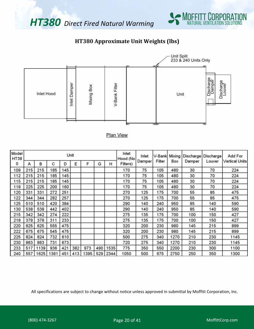
HT380 Approximate Unit Weights (lbs)
All specifications are subject to change without notice unless approved in submittal by Moffitt Corporation, Inc.

HT380 Direct Fired Natural Warming
MoffittCorp.com
Page 21 of 41
(800) 474-3267
HT380 Series Dampers
HT380 Series Discharge Louvers
On 240 discharge damper ONLY, there are (2) dampers side by side. Dimensions shown are for each damper.
Overall width of 240 discharge is 152 1/2. All dimensions shown in inches.
HT380 Direct Fired Natural Warming
MoffittCorp.com
Page 22 of 41
(800) 474-3267
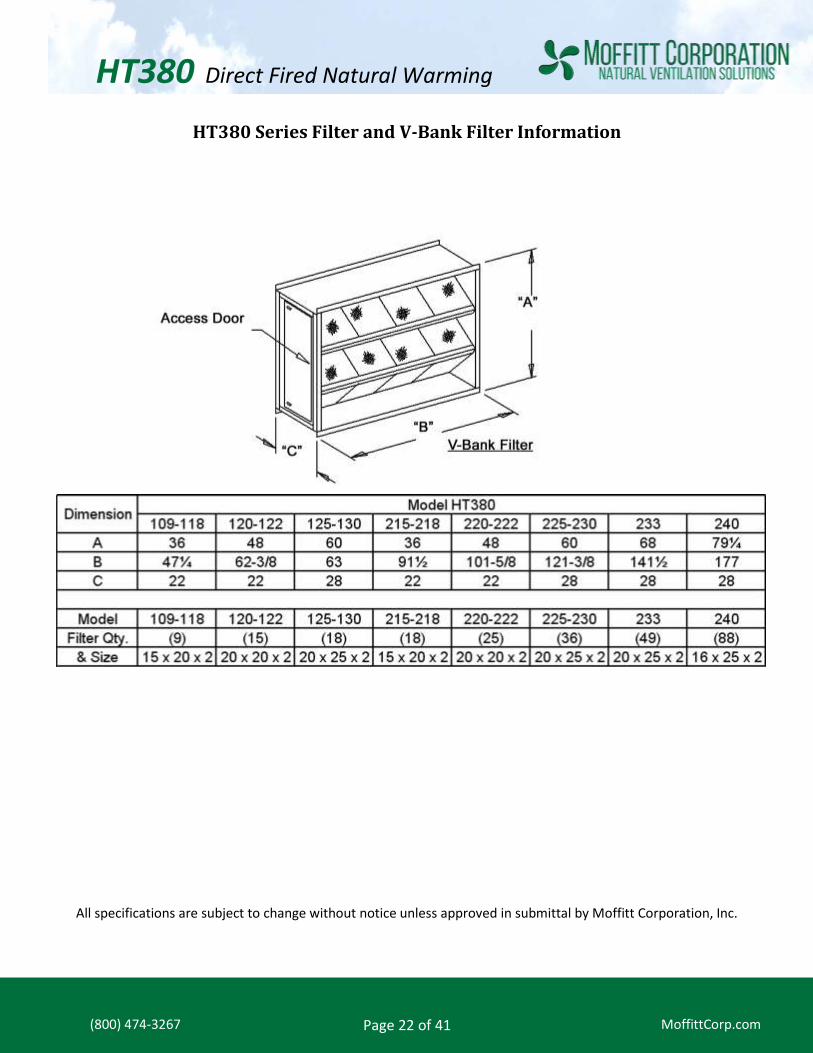
HT380 Series Filter and V-Bank Filter Information
All specifications are subject to change without notice unless approved in submittal by Moffitt Corporation, Inc.

HT380 Direct Fired Natural Warming
MoffittCorp.com
Page 23 of 41
(800) 474-3267
HT380 Series Mixing Box Information
NOTE: Filter dimensions and sizes are the same as V-Bank filter box. All dimensions shown in inches
All specifications are subject to change without notice unless approved in submittal by Moffitt Corporation, Inc.
Mixing Box R/A Air Probe Box

HT380 Direct Fired Natural Warming
MoffittCorp.com
Page 24 of 41
(800) 474-3267
HT380 Series Intake Hoods and Filter Information
Dimension (Inches)
Model HT380
109-112 115-118 120-122 125-130 215-218 220-222 225-230 233 240
A 36 36 48 60 36 48 60 68 79
B 47 1/4 47 1/4 62 3/8 63 91 1/2 101 5/8 121 3/8 140 1/2 174 1/2
C 32 32 38 1/2 53 32 44 1/2 56 1/2 56 1/2 51 1/2
MODEL 109-112 115-118 120-122 125-130 215-218 220-222 225-230 233 240
FILTER QTY. 4 8 12 30 16 18 66 69 64
& SIZE 16x20 16x20 20x20 15x20 16x20 20x25 15x20 16x20 20x25

HT380 Direct Fired Natural Warming
MoffittCorp.com
Page 25 of 41
(800) 474-3267
HT380 Direct Fire Heaters- Single Blower Models Information
NOTE:
Horsepower selections are based on system external static pressure. One or more of the following must
be added when applicable.
A. Fresh Air Inlet Hood & Birdscreen .13” W.C.
B. Fresh Air Inlet Hood with Filters .25” W.C.
C. Motor Operated Inlet Damper .13” W.C.
D. Motor Operated Discharge Damper .50” W.C.
E. V-Bank Filter Section .25” W.C.
F. Discharge Louver .13” W.C.
SELECTION GUIDE
1. Determine the required amount of replacement air (CFM) by computing the total amount of air
being exhausted.
2. Determine the total external static pressure by adding the pressure drops through all accessories
and ducts.
3. Select unit size and motor horsepower from table.
See chart on next page

HT380 Direct Fired Natural Warming
MoffittCorp.com
Page 26 of 41
(800) 474-3267
HT380 Direct Fire Heaters - Single Blower Models Selection Chart

HT380 Direct Fired Natural Warming
MoffittCorp.com
Page 27 of 41
(800) 474-3267
HT380 Direct Fire Heaters - Twin Blower Models Selection Chart

HT380 Direct Fired Natural Warming
MoffittCorp.com
Page 28 of 41
(800) 474-3267
HT380 Twin Blower Models- Burner Performance Table

HT380 Direct Fired Natural Warming
MoffittCorp.com
Page 29 of 41
(800) 474-3267
HT380 Twin Blower Models - Burner Performance Table cont.

HT380 Direct Fired Natural Warming
MoffittCorp.com
Page 30 of 41
(800) 474-3267
HT380 Twin Blower Models - Burner Performance Table

HT380 Direct Fired Natural Warming
MoffittCorp.com
Page 31 of 41
(800) 474-3267
HT380 Twin Blower Models - Burner Performance Table cont.

HT380 Direct Fired Natural Warming
MoffittCorp.com
Page 32 of 41
(800) 474-3267
HT380 Series Gas Piping Layout
COMPONENT IDENTIFICATION:
NOTES:
1. Vent limiting devices provided wherever possible, when venting is required * the venting to outside
is by others on indoor units and furnished by factory on outdoor units.
2. Units with 900 MBH and less use a pressure regulator (not shown) for high fire setting.
3. 4,400 MBH and above will require a minimum inlet pressure of 1 PSIG. For inlet pressures under 1
PSIG - Consult factory.
4. For inlet pressure under 10” W.C. - Consult factory.
5. Units that are listed to the Z83.1 standard, carry both ETL and CETL approvals.
6. Standard manifold meets EM requirements for inputs under 2,500 MBH for ETL listed units.
7. Standard manifold meets IRI requirements for ETL listed units.
8. High gas pressure regulator required if inet pressure exceeds 1/2 PSIG for inputs up to and including
900 MBH or inlet pressures over 5 PSIG for inputs greater than 900 MBH.
See next page for drawings
VG-03 Auxiliary gas valve
VG-04 N/O vent valve
VG-07 Modulating valve
PS-04 Low gas pressure switch
PS-07 High gas pressure switch
PS-10 High velocity pressure switch
PS-11 Low velocity pressure switch
GP-01 High gas pressure regulator
GP-02 Main gas shut-off valve
GP-09 Pilot gas pressure regulator
GP-11 Main test firing shut-off valve
GP-13 Pilot gas shut-off valve
GP-27 Orifice needle valve
VG-01 Pilot gas valve
VG-02 Main gas valve

HT380 Direct Fired Natural Warming
MoffittCorp.com
Page 33 of 41
(800) 474-3267
HT380 Series Gas Piping Layout cont.

HT380 Direct Fired Natural Warming
MoffittCorp.com
Page 34 of 41
(800) 474-3267
MDT Control System
APPLICATION:
Modulating Discharge Temperature Control
COMPONENT I.D.
1. Unit DDC Controller
2. Signal Conditioner
3. Modulating Gas Valve
4. Inlet Air Sensor
5. Discharge Air Sensor
6. Remote Control Station
INCLUDES:
Discharge air sensor (5) mounted in unit
discharge with remote mounted 4 x 4 box cover
(6) including manual potentiometer to enable
unit and adjust temperature set point, Fan On
Light, Burner On Light, and Cool On Light.
Additional potentiometer is provided if optional
return damper section for manual or mixed air
control is ordered.
Discharge Temperature
SET here

HT380 Direct Fired Natural Warming
MoffittCorp.com
Page 35 of 41
(800) 474-3267
MRT Control System
APPLICATION:
Modulating Room Temperature Control
COMPONENT I.D.
7. Unit DDC Controller
8. Signal Conditioner
9. Modulating Gas Valve
10. Inlet Air Sensor
11. Discharge Air Sensor
12. Remote Control Station
INCLUDES:
Discharge air sensor (5) mounted in unit
discharge with remote mounted 4 x 4 box cover
(7) including manual potentiometer to enable
unit and adjust temperature set point, Fan On
Light, Burner On Light, and Cool On Light. Also
includes RS-std room sensor (6) (does not allow
remote room set point adjustment). Additional
potentiometer is provided if optional return
damper section for manual or mixed air control
is ordered.
Space Temperature
SET Here
Space Temperature
SENSED Here

HT380 Direct Fired Natural Warming
MoffittCorp.com
Page 36 of 41
(800) 474-3267
MRT Pro Control System
APPLICATION: Modulating Room Temperature Control with RS-Pro room sensor allowing after hours unit enable, room set point adjustment and digital temperature readout. COMPONENT I.D.
1. Unit DDC Controller
2. Signal Conditioner
3. Modulating Gas Valve
4. Inlet Air Sensor
5. Discharge Air Sensor
6. Room Thermostat
INCLUDES: Discharge air sensor (5) mounted in unit discharge with remote mounted RS-Pro room sensor (6) with push buttons for room set point adjustment and digital temperature readout. On units with optional return air damper section a remote mounted 4 x 4 box cover is provided with potentiometer for manual or mixed air control.
Space Temperature SET and
SENSED here

HT380 Direct Fired Natural Warming
MoffittCorp.com
Page 37 of 41
(800) 474-3267
MRT Expert Control System
APPLICATION:
Modulating Room Temperature Control with
BACView controller allowing after hours unit
enable, room set point adjustment, operating
feedback, monitoring of alarm status and digital
temperature readout with RS-std room sensor.
INCLUDES:
Discharge air sensor (5) mounted in unit
discharge with remote mounted BACView
controller (7) to set space temp, operating
schedules, and optional damper control set
points. Service information, operating feedback
and alarm status can also be monitored. Also
includes a RS-std room sensor (6).
COMPONENT I.D.
1. Unit DDC Controller
2. Signal Conditioner
3. Modulating Gas Valve
4. Inlet Air Sensor
5. Discharge Air Sensor
6. Room Thermostat
7. BACView Interface
Space Temperature SET here
Space
Temperature
SENSED here

HT380 Direct Fired Natural Warming
MoffittCorp.com
Page 38 of 41
(800) 474-3267
Typical Wiring Diagram - Model HT380- Page 1
COMPONENT IDENTIFICATION
CB-09 CONTROL CIRCUIT TRANSFORMER BREAKER
FL-02 HIGH TEMPERATURE LIMIT SWITCH
FL-05 SUPPLY AIR FIRESTAT (OPTIONAL)
FL-06 RETURN AIR FIRESTAT (OPTIONAL)
GA-03 COMBINATION CO & NO2 DETECTOR (OPTIONAL)
KP-01 KEYPAD / DISPLAY MODULE (OPTIONAL)
LT-05 BURNER ON LIGHT (REMOTE)
LT-15 FAN ON LIGHT (REMOTE)
LT-31 COOLING ON LIGHT (REMOTE)
LT-59 CLOGGED FILTER LIGHT (REMOTE)
MP-05 DAMPER CONTROL POTENTIOMETER (OPTIONAL)
MP-15 UNIT ENABLE POTENTIOMETER
MT-01 MAIN SUPPLY FAN MOTOR
MT-12 DISCHARGE DAMPER MOTOR (OPTIONAL)
MT-13 INLET DAMPER MOTOR (OPTIONAL)
MT-14 MIXING BOX DAMPER MOTOR (OPTIONAL)
OL-01 MAIN FAN MOTOR OVERLOAD
PS-04 LOW GAS PRESSURE SWITCH (OPTIONAL)
PS-07 HIGH GAS PRESSURE SWITCH (OPTIONAL)
PS-10 HIGH VELOCITY SWITCH
PS-11 LOW VELOCITY SWITCH
PS-12 CLOGGED FILTER SWITCH (OPTIONAL)
PT-13 BUILDING PRESSURE TRANSDUCER (OPTIONAL)
PT-15 FLOW STATION PRESSURE TRANSDUCER (OPTIONAL)
RE-02 FLAME SAFEGUARD RELAY
RE-09 FLAME FAILURE RELAY
RE-12 CLOGGED FILTER RELAY (OPTIONAL)
RE-14 HOLDING RELAY (OPTIONAL)
RE-26 ELECTRONIC RELAY
RE-27 BURNER STATUS RELAY
RE-28 BURNER ENABLE RELAY
RE-34 COOLING ENABLE RELAY
RE-35 COOLING INTERLOCK RELAY
RE-56 SAFETY CIRCUIT STATUS RELAY
RE-57 UNIT ENABLE RELAY
RE-65 FAN STATUS RELAY
RE-75 FLAME SUPERVISION SWITCHING RELAY
RE-78 INTERLOCKING RELAY (OPTIONAL)
RE-80 LOW ALERT RELAY (OPTIONAL)
RE-81 HIGH ALERT RELAY (OPTIONAL)
RE-90 ALARM STATUS RELAY
RS-01 RESISTOR 1K OHM
RS-02 RESISTOR 2K OHM
RS-03 RESISTOR 4.02K OHM

HT380 Direct Fired Natural Warming
MoffittCorp.com
Page 39 of 41
(800) 474-3267
Typical Wiring Diagram - Model HT380- Page 2

HT380 Direct Fired Natural Warming
MoffittCorp.com
Page 40 of 41
(800) 474-3267
Typical Wiring Diagram - Model HT380- Page 3

HT380 Direct Fired Natural Warming
MoffittCorp.com
Page 41 of 41
(800) 474-3267
Typical Wiring Diagram - Model HT380- Page 4