Embed Size (px)
Citation preview
VIESMANNOperating and serviceinstructionsfor contractors
Vitomax 200-HWType M238Oil/gas fired high pressure hot water boilerCombustion output 4.0 to 18.2 MW
VITOMAX 200-HW
5592 548 GB 06/2007 Please keep safe.
Please follow these safety instructions closely to prevent accidents andmaterial losses.
Safety instructions explained
DangerThis symbol warns against therisk of injury.
! Please noteThis symbol warns against therisk of material losses andenvironmental pollution.
NoteDetails identified by the word "Note"contain additional information.
Target group
These instructions are exclusivelydesigned for qualified personnel.&Work on gas equipment must onlybe carried out by a qualified gas fit-ter.
&Work on electrical equipment mustonly be carried out by a qualifiedelectrician.
& The system must be commissionedby the system installer or a qualifiedperson authorised by the installer.
Regulations
Observe the following when workingon this system& all legal instructions regarding theprevention of accidents,
& all legal instructions regardingenvironmental protection,
& the Code of Practice of relevanttrade associations,
& all current safety regulations asdefined by DIN, EN, DVGW, TRGI,TRF, VDE and all locally applicablestandards.
If you smell gas
DangerEscaping gas can lead toexplosions which may result inserious injury.& Never smoke. Prevent nakedflames and sparks. Neverswitch lights or electricalappliances ON or OFF.
& Close the gas shut-off valve.& Open windows and doors.& Remove all people from thedanger zone.
& Notify your gas or electricitysupplier from outside thebuilding.
& Shut off the electricity supplyto the building from a safeplace (outside the building).
If you smell flue gas
DangerFlue gas can lead to life-threa-tening poisoning.& Shut down the heating sys-tem.
& Ventilate the boiler room.& Close all doors leading to theliving space.
Safety instructions
2
Safety instructions
5592548GB
Working on the system
&When using gas as fuel, also closethe main gas shut-off valve andsafeguard against unauthorisedreopening.
& Isolate the system from the powersupply and check that it is no longer'live', e.g. by removing a separatefuse or by means of a main isolator.
& Safeguard the system againstunauthorised reconnection.
! Please noteElectronic modules can bedamaged by electro-static dis-charges.Touch earthed objects, such asheating or water pipes, to dis-charge static loads.
Repair work
! Please noteRepairing components whichfulfil a safety function can com-promise the safe operation ofyour heating system.Replace faulty componentsonly with original Viessmannspare parts.
Ancillary components, spare andwearing parts
! Please noteSpare and wearing parts whichhave not been tested togetherwith the heating system cancompromise its function. Instal-ling non-authorised compo-nents and non-approvedmodifications/conversion cancompromise safety and mayinvalidate our warranty.For replacements, use only ori-ginal spare parts fromViessmann or those which areapproved by Viessmann.
Safety instructions (cont.)
3
Safety instructions5592548GB
Operating informationOperating tips ............................................................................................. 5Operational checks ..................................................................................... 5Shutdown ................................................................................................... 6Maintenance information............................................................................. 8
Commissioning, inspection, maintenanceSteps - commissioning, inspection and maintenance ................................... 9Further details regarding the individual steps .............................................. 11
Additional informationStandard values for water quality ............................................................... 20
Commissioning/service reports ............................................................... 22
Keyword index .......................................................................................... 27
Index
4
Index
5592548GB
According to the Pressure EquipmentDirective 97/23/EC, a steam boilercategory IV may only be taken intouse when the relevant authority hasgranted permission for the installationof the system, and an authorisedexpert has tested the system.The system must be commissioned bythe system installer or a qualified per-son authorised by the installer as wellthe relevant expert.Record all actual values in a commis-sioning/service report. These valuesmust be confirmed by the expert andthe system user.According to the Pressure EquipmentDirective 97/23/EC, hot water boilerscategory IV may only be operated,supervised and maintained by atrained boilerman.
The relevant authority may grant,upon application, permission to oper-ate the boiler without permanentsupervision, subject to it beingequipped in accordance with EN12953 part 6.In systems comprising several boi-lers, of which one is constantly usedas standby boiler, only change theoperation over in longer intervals, e.g.during the annual inspection of thetotal system.We would recommend that you oper-ate the boiler constantly at therequired operating pressure and tem-perature.The continued boiler operation is stilladvantageous, even if no heat isdrawn off for a longer period of time.
Operational checks
DangerBoiler components that are notthermally insulated can be sub-ject to high temperatures thatcan result in burns.Take care with hot surfaces.
Subject to the safety equipment fittedand the details in the permit certifi-cate, either monitor the correct boileroperation constantly, every 24 hoursor every 72 hours.
Determine the extent of checksrequired in accordance with TRD 601,sh. 1, section 7 [or local regulations].Test the chemical composition of theboiler water and feedwater constantlyin accordance with EN 12953 part 10and VdTÜV datasheet 1466 [or localregulations].Carry out the following checks dailyor every 72 hours, subject to boilerversion and the manufacturer's speci-fication (see also TRD 601, sh. 1):& Blow down the boiler (only for boi-lers without automatic facility;briefly open the valve two or threetimes at operating pressure).
& Check the water level limiter.& Check the feed and boiler water.
Operating tips
5
Operating information5592548GB
Carry out the following checksmonthly:& Check the function of the safetyvalve.
& Check the function of all control andsafety equipment.
& Check all connections and closuresfor leaks.
& Check the installation room ventila-tion.
Have someone carry out the followingchecks every six months (in accor-dance with TRD 602 and 604):& Check the safety equipment.& Check the burner.& Check the thermal insulation on thehot gas side, i.e. on lids and doors.
Record the results of the daily,monthly and biannual checks in a log.
Shutdown
To prevent corrosion setting in during idle periods, when the boiler is not pres-surised, conserve the boiler surfaces on the flue gas and water sides, subject tothe length of the period during which the boiler is taken out of use. There is a dif-ferentiation between wet conservation (during which exposure to oxygen is tobe avoided) and dry conservation (during which moisture levels are to be mini-mised).
Brief interruption of operation (1 to 2 days)
Water side
Recommendation: Maintain the boilerpressure and temperature. Where thatis not possible and the boiler shouldbe depressurised for several days, wewould recommend the following:
To prevent oxygen corrosion, add anoxygen binder with twice to threetimes the standard dose to the feed-water from approx. one hour beforethe boiler is shut down.
Flue gas side
Keep the heating surfaces dry.Remove severe contamination as itbinds moisture.
Operational checks (cont.)
6
Operating information
5592548GB
Longer interruptions of operation
Water side
Wet conservation, as long as there is no risk of frost
1. Fill the boiler up to the highest pos-sible level with treated feedwater.To prevent oxygen corrosion, addan oxygen binder to the boiler water(e.g. sodium sulphite) in accor-dance with the manufacturer'sinstructions. For this, ensure goodadmixing with the boiler water(thermal or mechanical agitation).
2. If, in multi-boiler systems, onlysome boilers must be conserved,these can be filled with desalinatedboiler water from the boilers thatremain in use, which will also main-tain the temperature.
3. Maintaining pressure in a fully filledboiler using nitrogen (preferablynitrogen 5.0) of 0.1 to 0.2 bar canprevent corrosion.
Dry conservation in case there is a risk of frost or in case of longer idleperiods
Drain the boiler at a temperaturebetween 120 and 140 °C, then openthe fittings on the water side.Dry the boiler thoroughly and fill withdesiccant (e.g. silica gel) in accor-dance with the manufacturer's details.
Ensure that the desiccant does notcome into contact with the boilermaterial. Then close the boiler again.Check in regular intervals whether thedesiccant is still able to absorb moist-ure.
Flue gas side
Thoroughly clean and dry the sur-faces on the flue gas side.Maintain the alkaline balance of thewash water (pH 8-9, in case of ammo-nia pH 10).
After the surfaces have been driedcompletely, conserve them with a thinfilm of graphite or boiled oil.
Shutdown (cont.)
7
Operating information5592548GB
Keep the surfaces dry during the idleperiods (by inserting desiccant (e.g.silica gel) or by air changes from aconnected dryer).
Further details
For further details, see the operatinginstructions for conservation on thewater and hot gas side or the VdTÜVdatasheets (no. 1465, Oct. 1978) andthe VGB (no. R116H, 1981) [or localregulations].
Maintenance information
The maintenance of a high pressurehot water boiler is specified by theTRD [or local] regulations.
DangerBoiler components that are notthermally insulated can be sub-ject to high temperatures thatcan cause burns.Take care with hot surfaces.
Shutdown (cont.)
8
Operating information
5592548GB
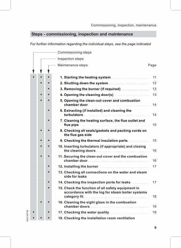
For further information regarding the individual steps, see the page indicated
Commissioning steps
Inspection steps
Maintenance steps Page
! ! !
����
�������
����������
• • • 01. Starting the heating system . . . . . . . . . . . . . . . . . . . . . . . . . . . . . . . . . . . . . . . . . . . . . . 11
• • 02. Shutting down the system . . . . . . . . . . . . . . . . . . . . . . . . . . . . . . . . . . . . . . . . . . . . . . . . . 12
• 03. Removing the burner (if required) . . . . . . . . . . . . . . . . . . . . . . . . . . . . . . . . . . 13
• • 04. Opening the cleaning door(s) . . . . . . . . . . . . . . . . . . . . . . . . . . . . . . . . . . . . . . . . . . . 13
• • 05. Opening the clean-out cover and combustionchamber door . . . . . . . . . . . . . . . . . . . . . . . . . . . . . . . . . . . . . . . . . . . . . . . . . . . . . . . . . . . . . . . . . . . . . . . . . 14
• 06. Extracting (if installed) and cleaning theturbulators . . . . . . . . . . . . . . . . . . . . . . . . . . . . . . . . . . . . . . . . . . . . . . . . . . . . . . . . . . . . . . . . . . . . . . . . . . . . . . . 14
• 07. Cleaning the heating surface, the flue outlet andflue pipe . . . . . . . . . . . . . . . . . . . . . . . . . . . . . . . . . . . . . . . . . . . . . . . . . . . . . . . . . . . . . . . . . . . . . . . . . . . . . . . . . . . . 15
• • 08. Checking all seals/gaskets and packing cords onthe flue gas side
• • 09. Checking the thermal insulation parts . . . . . . . . . . . . . . . . . . . . . . . . . . 15
• • 10. Inserting turbulators (if appropriate) and closingthe cleaning doors . . . . . . . . . . . . . . . . . . . . . . . . . . . . . . . . . . . . . . . . . . . . . . . . . . . . . . . . . . . . . . . . 16
• • 11. Securing the clean-out cover and the combustionchamber door . . . . . . . . . . . . . . . . . . . . . . . . . . . . . . . . . . . . . . . . . . . . . . . . . . . . . . . . . . . . . . . . . . . . . . . . . 16
• 12. Installing the burner . . . . . . . . . . . . . . . . . . . . . . . . . . . . . . . . . . . . . . . . . . . . . . . . . . . . . . . . . . . . . 17
• 13. Checking all connections on the water and steamside for leaks
• 14. Checking the inspection ports for leaks . . . . . . . . . . . . . . . . . . . . . . 17
• 15. Check the function of all safety equipment inaccordance with the log for steam boiler systemscategory IV. . . . . . . . . . . . . . . . . . . . . . . . . . . . . . . . . . . . . . . . . . . . . . . . . . . . . . . . . . . . . . . . . . . . . . . . . . . . . . . 18
• • 16. Cleaning the sight glass in the combustionchamber doors . . . . . . . . . . . . . . . . . . . . . . . . . . . . . . . . . . . . . . . . . . . . . . . . . . . . . . . . . . . . . . . . . . . . . . . 19
• • 17. Checking the water quality . . . . . . . . . . . . . . . . . . . . . . . . . . . . . . . . . . . . . . . . . . . . . . . . 19
• • • 18. Checking the installation room ventilation
Steps - commissioning, inspection and maintenance
9
Commissioning, inspection, maintenance5592548GB
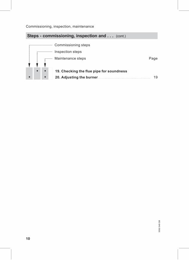
Commissioning steps
Inspection steps
Maintenance steps Page
! ! !
����
�������
����������
• • 19. Checking the flue pipe for soundness
• • 20. Adjusting the burner . . . . . . . . . . . . . . . . . . . . . . . . . . . . . . . . . . . . . . . . . . . . . . . . . . . . . . . . . . . . 19
Steps - commissioning, inspection and . . . (cont.)
10
Commissioning, inspection, maintenance
5592548GB
Starting the heating system
Details provided by the burnermanufacturer and regardingaccessories
1. Check that the turbulators (ifinstalled) are fully pushed into thehot gas flues (open the cleaningdoor(s)).
2. Check that the installation roomventilation is open.
3. Check the function of the watertreatment system.
4. Fill the boiler with water and venti-late it.
NoteThe water in hot water boilersmust comply with EN 12953 part10; see also "Standard values forwater quality" on page 20.
5. Check all fitted components, suchas pipework, valves, regulators,pumps etc. for function and leaks.
6. Check the system pressure.
7. Check the fuel oil level or the gassupply pressure.
8. Open the flue gas damper (ifinstalled).
9. Check that the cleaning aperture(s) on the flue outlet is/are closed.
10. Open the gas or oil supply lineshut-off valves.
11. Switch ON the main isolator, theswitch for the boiler drives andthe burner control switch in thisorder (observe the burner manu-facturer’s operating instructions).
12. Start the boiler at a low output(max. 30%) and gradually heat upto a temperature of approx. 30 Kbelow operating temperature.
13. After the required flow tempera-ture has been reached, graduallyopen the boiler return valve andpossibly the feedwater valve aswell as the boiler flow valve.
14. Only then enable the full burnerload.
15. When heating the system fromcold (also when restarting aftermaintenance and cleaning work),prevent all heat transfer to consu-mers, to clear the dew point rangeas quickly as possible.
16. After the operating temperaturehas been reached, sequentiallyswitch on the heat consumers andchange over to automatic mode.
Further details regarding the individual steps
11
Commissioning, inspection, maintenance5592548GB
17. Check the fittings for leaks prior toand during the heat-up phase andretighten, where required.Retighten all fittings at max. per-missible operating pressure. Tor-que values under cold and hotconditions:
Closure Dimen-sions
Torque
Hand hole 100 x 150,M16
100 Nm
Head hole 220 x 320,M20
200 Nm
Manhole 320 x 420,M24
350 Nm
18. Check the boiler door(s) andclean-out cover after approx. 50hours for leaks and retighten allscrews.
Shutting down the system
DangerOpening the boiler connectionsand openings whilst the boileris under pressure can lead to ahigh risk of severe injury.Only open the connections onthe water and steam side andinspection apertures after theboiler has been completely de-pressurised.
1. Close the shut-off valves in the oillines (at the oil tank and filter) orthe gas shut-off valve.
2. Switch OFF the burner.
3. Isolate the system from the powersupply.
4. Close all valves.
Further details regarding the individual steps (cont.)
12
Commissioning, inspection, maintenance
5592548GB
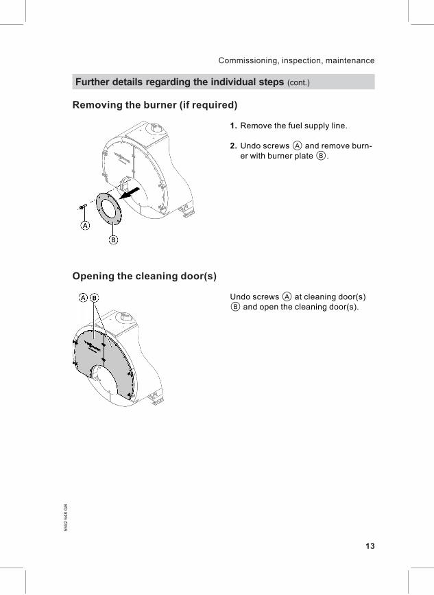
Removing the burner (if required)
1. Remove the fuel supply line.
2. Undo screwsA and remove burn-er with burner plateB.
Opening the cleaning door(s)
Undo screwsA at cleaning door(s)B and open the cleaning door(s).
Further details regarding the individual steps (cont.)
13
Commissioning, inspection, maintenance5592548GB
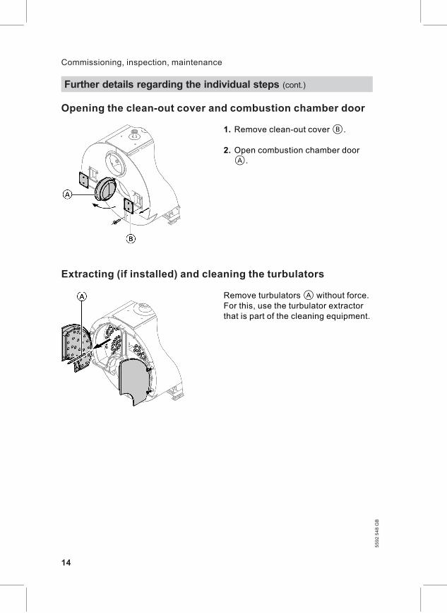
Opening the clean-out cover and combustion chamber door
1. Remove clean-out coverB.
2. Open combustion chamber doorA.
Extracting (if installed) and cleaning the turbulators
Remove turbulatorsA without force.For this, use the turbulator extractorthat is part of the cleaning equipment.
Further details regarding the individual steps (cont.)
14
Commissioning, inspection, maintenance
5592548GB
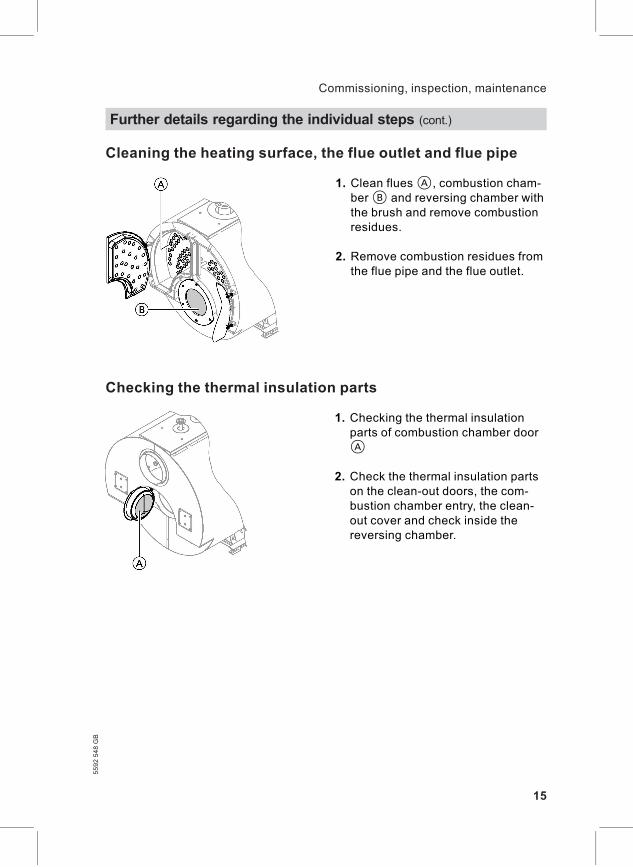
Cleaning the heating surface, the flue outlet and flue pipe
1. Clean fluesA, combustion cham-berB and reversing chamber withthe brush and remove combustionresidues.
2. Remove combustion residues fromthe flue pipe and the flue outlet.
Checking the thermal insulation parts
1. Checking the thermal insulationparts of combustion chamber doorA
2. Check the thermal insulation partson the clean-out doors, the com-bustion chamber entry, the clean-out cover and check inside thereversing chamber.
Further details regarding the individual steps (cont.)
15
Commissioning, inspection, maintenance5592548GB
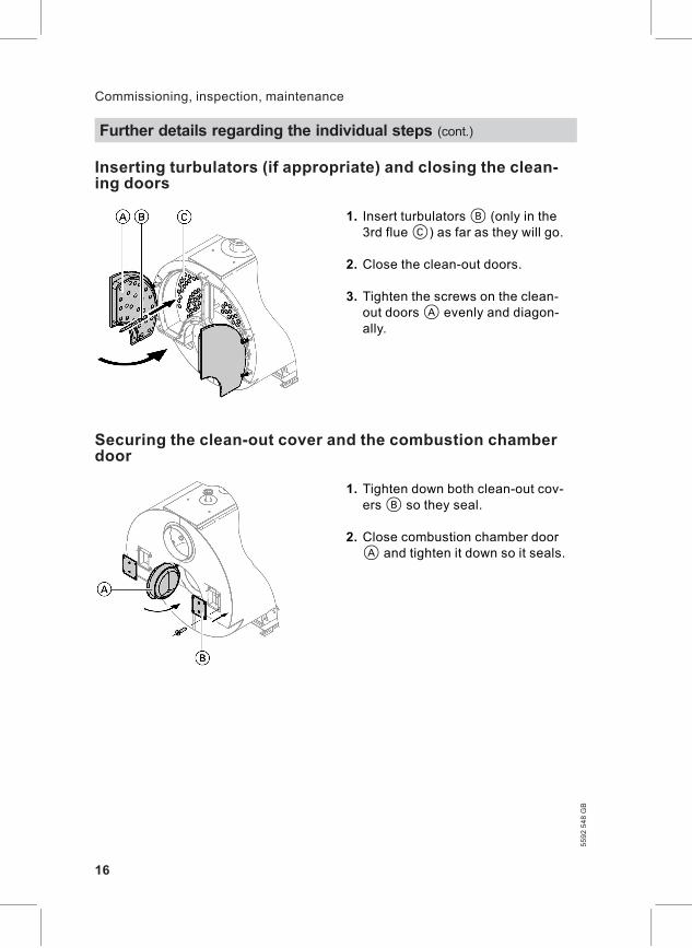
Inserting turbulators (if appropriate) and closing the clean-ing doors
1. Insert turbulatorsB (only in the3rd flueC) as far as they will go.
2. Close the clean-out doors.
3. Tighten the screws on the clean-out doorsA evenly and diagon-ally.
Securing the clean-out cover and the combustion chamberdoor
1. Tighten down both clean-out cov-ersB so they seal.
2. Close combustion chamber doorA and tighten it down so it seals.
Further details regarding the individual steps (cont.)
16
Commissioning, inspection, maintenance
5592548GB
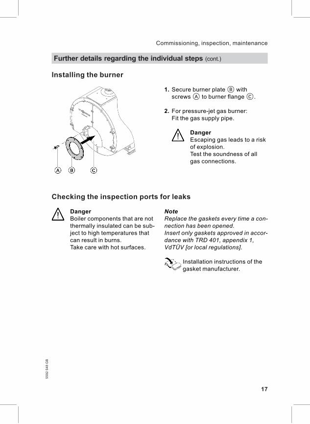
Installing the burner
1. Secure burner plateB withscrewsA to burner flangeC.
2. For pressure-jet gas burner:Fit the gas supply pipe.
DangerEscaping gas leads to a riskof explosion.Test the soundness of allgas connections.
Checking the inspection ports for leaks
DangerBoiler components that are notthermally insulated can be sub-ject to high temperatures thatcan result in burns.Take care with hot surfaces.
NoteReplace the gaskets every time a con-nection has been opened.Insert only gaskets approved in accor-dance with TRD 401, appendix 1,VdTÜV [or local regulations].
Installation instructions of thegasket manufacturer.
Further details regarding the individual steps (cont.)
17
Commissioning, inspection, maintenance5592548GB
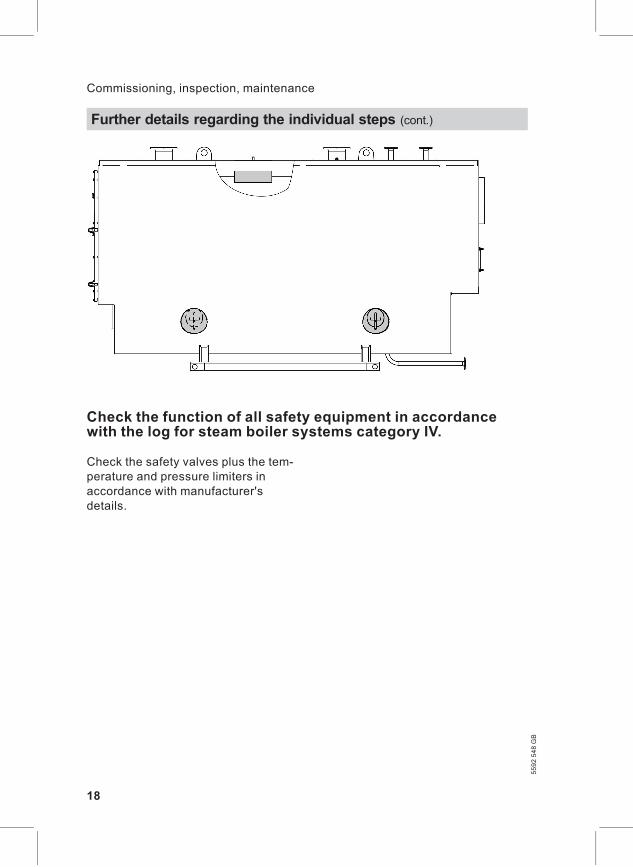
Check the function of all safety equipment in accordancewith the log for steam boiler systems category IV.
Check the safety valves plus the tem-perature and pressure limiters inaccordance with manufacturer'sdetails.
Further details regarding the individual steps (cont.)
18
Commissioning, inspection, maintenance
5592548GB
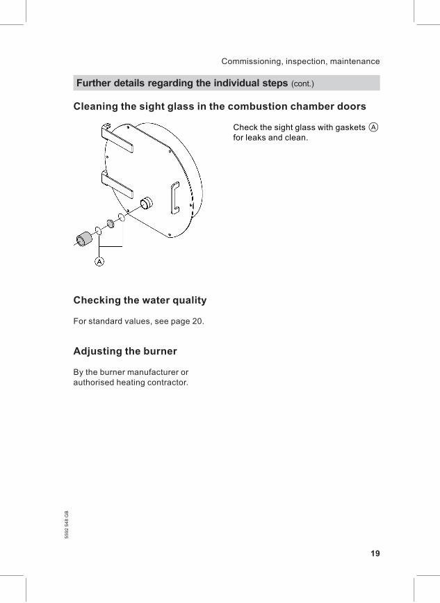
Cleaning the sight glass in the combustion chamber doors
Check the sight glass with gasketsAfor leaks and clean.
Checking the water quality
For standard values, see page 20.
Adjusting the burner
By the burner manufacturer orauthorised heating contractor.
Further details regarding the individual steps (cont.)
19
Commissioning, inspection, maintenance5592548GB
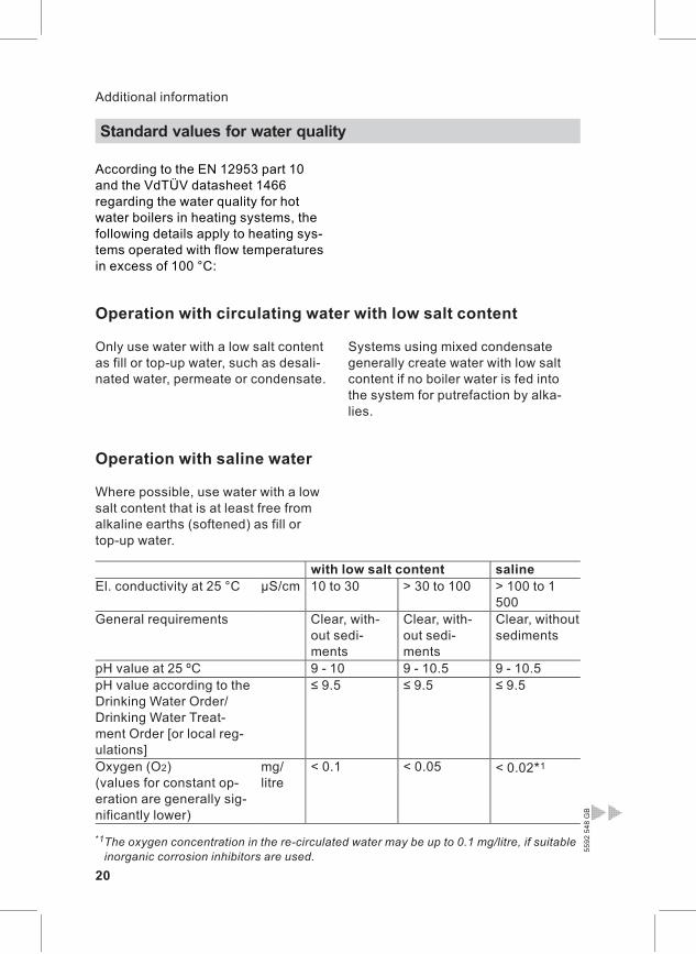
According to the EN 12953 part 10and the VdTÜV datasheet 1466regarding the water quality for hotwater boilers in heating systems, thefollowing details apply to heating sys-tems operated with flow temperaturesin excess of 100 °C:
Operation with circulating water with low salt content
Only use water with a low salt contentas fill or top-up water, such as desali-nated water, permeate or condensate.
Systems using mixed condensategenerally create water with low saltcontent if no boiler water is fed intothe system for putrefaction by alka-lies.
Operation with saline water
Where possible, use water with a lowsalt content that is at least free fromalkaline earths (softened) as fill ortop-up water.
with low salt content salineEl. conductivity at 25 °C μS/cm 10 to 30 > 30 to 100 > 100 to 1
500General requirements Clear, with-
out sedi-ments
Clear, with-out sedi-ments
Clear, withoutsediments
pH value at 25 ºC 9 - 10 9 - 10.5 9 - 10.5pH value according to theDrinking Water Order/Drinking Water Treat-ment Order [or local reg-ulations]
≤ 9.5 ≤ 9.5 ≤ 9.5
Oxygen (O2)(values for constant op-eration are generally sig-nificantly lower)
mg/litre
< 0.1 < 0.05 < 0.02*1
Standard values for water quality
20
Additional information
5592548GB
*1The oxygen concentration in the re-circulated water may be up to 0.1 mg/litre, if suitableinorganic corrosion inhibitors are used.
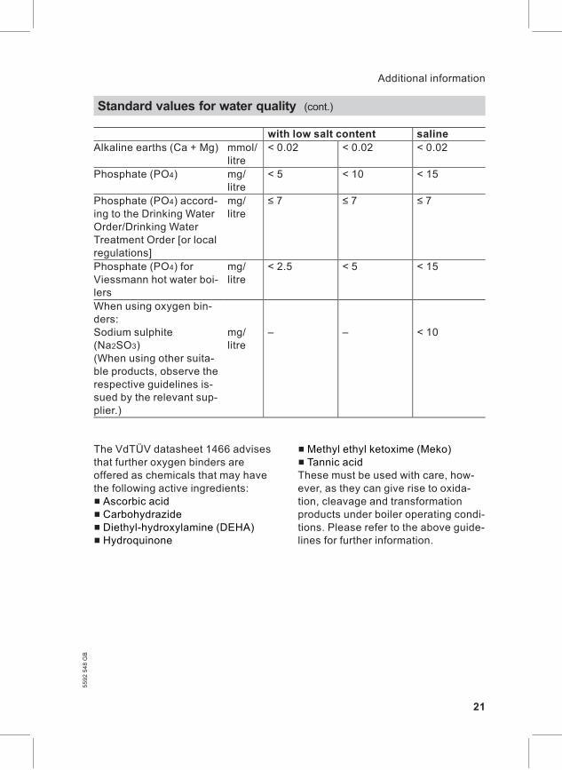
with low salt content salineAlkaline earths (Ca + Mg) mmol/
litre< 0.02 < 0.02 < 0.02
Phosphate (PO4) mg/litre
< 5 < 10 < 15
Phosphate (PO4) accord-ing to the Drinking WaterOrder/Drinking WaterTreatment Order [or localregulations]
mg/litre
≤ 7 ≤ 7 ≤ 7
Phosphate (PO4) forViessmann hot water boi-lers
mg/litre
< 2.5 < 5 < 15
When using oxygen bin-ders:Sodium sulphite(Na2SO3)(When using other suita-ble products, observe therespective guidelines is-sued by the relevant sup-plier.)
mg/litre
– – < 10
The VdTÜV datasheet 1466 advisesthat further oxygen binders areoffered as chemicals that may havethe following active ingredients:& Ascorbic acid& Carbohydrazide& Diethyl-hydroxylamine (DEHA)& Hydroquinone
& Methyl ethyl ketoxime (Meko)& Tannic acidThese must be used with care, how-ever, as they can give rise to oxida-tion, cleavage and transformationproducts under boiler operating condi-tions. Please refer to the above guide-lines for further information.
Standard values for water quality (cont.)
21
Additional information5592548GB
Commissioning Service Service
date:
by:
Service Service Service
date:
by:
Service Service Service
date:
by:
Service Service Service
date:
by:
Service Service Service
date:
by:
Commissioning/service reports
22
Commissioning/service reports
5592548GB
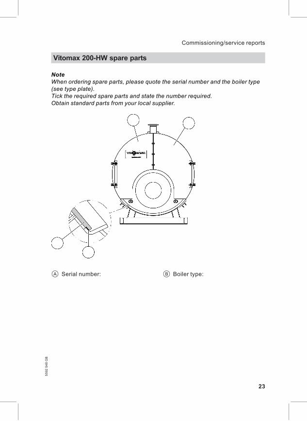
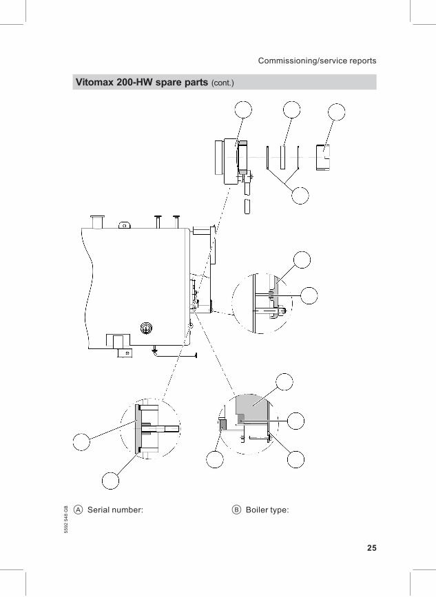
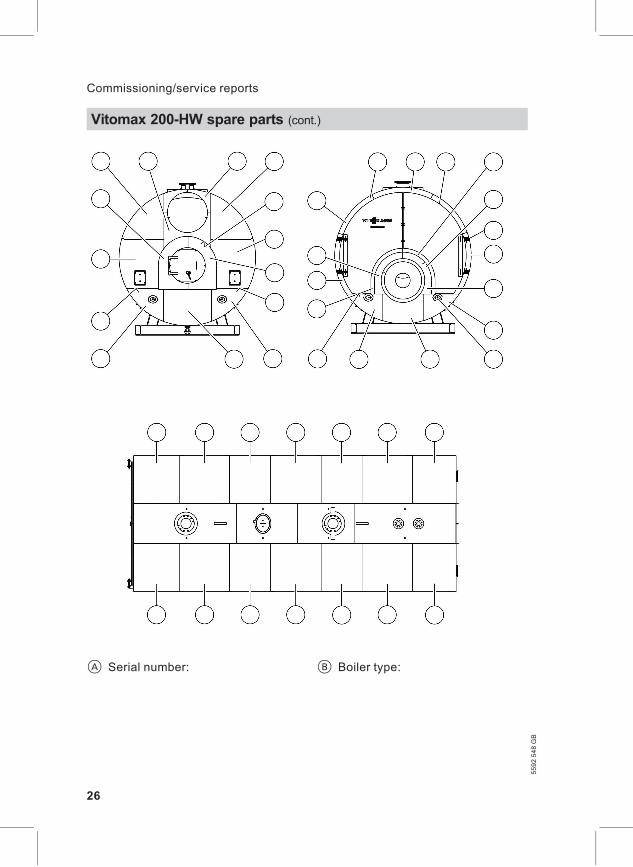
NoteWhen ordering spare parts, please quote the serial number and the boiler type(see type plate).Tick the required spare parts and state the number required.Obtain standard parts from your local supplier.
A Serial number: B Boiler type:
Vitomax 200-HW spare parts
23
Commissioning/service reports5592548GB
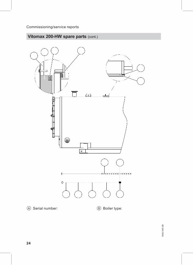
A Serial number: B Boiler type:
Vitomax 200-HW spare parts (cont.)
24
Commissioning/service reports
5592548GB
A Serial number: B Boiler type:
Vitomax 200-HW spare parts (cont.)
25
Commissioning/service reports5592548GB
A Serial number: B Boiler type:
Vitomax 200-HW spare parts (cont.)
26
Commissioning/service reports
5592548GB
BBurner installation . . . . . . . . . . . . . . . . . . . . . . . . 17Burner, removal . . . . . . . . . . . . . . . . . . . . . . . . . . . 13
CCleaning door, opening . . . . . . . . . . . . . . . . 13Clean-out cover, opening. . . . . . . . . . . . . . 14Clean-out cover, securing . . . . . . . . . . . . . 16Combustion chamber door, opening . .
. . . . . . . . . . . . . . . . . . . . . . . . . . . . . . . . . . . . . . . . . . . . . . .14
FFill and top-up water. . . . . . . . . . . . . . . . . . . . . 20Flue outlet and flue pipe, cleaning . 15Flue supply line . . . . . . . . . . . . . . . . . . . . . . . . . . . 13
MMaintenance information . . . . . . . . . . . . . . . . 8
OOperational checks . . . . . . . . . . . . . . . . . . . . . . . . 5
SSafety valve, checking . . . . . . . . . . . . . . . . . . . 6Saline water . . . . . . . . . . . . . . . . . . . . . . . . . . . . . . . . 20Shutdown. . . . . . . . . . . . . . . . . . . . . . . . . . . . . . . . . 6, 12Sight glass, cleaning . . . . . . . . . . . . . . . . . . . . 19Starting the heating system . . . . . . . . . . . 11
TThermal insulation parts, checking 15Turbulators, extracting . . . . . . . . . . . . . . . . . 14Turbulators, inserting . . . . . . . . . . . . . . . . . . . 16
WWater quality . . . . . . . . . . . . . . . . . . . . . . . . . . . . . . . 20Water with a low salt content . . . . . . . . . 20
Keyword index
27
Keyword index5592548GB
28
Printedonenvironmentally
friendly,
chlorine-freebleach
edpaper
5592548GB
Subject
totech
nicalm
odifications.
Viessmann Werke GmbH&Co KGD-35107 AllendorfTelephone: +49 6452 70-0Fax: +49 6452 70-2780www.viessmann.com
Viessmann LimitedHortonwood 30, TelfordShropshire, TF1 7YP, GBTelephone: +44 1952 675000Fax: +44 1952 675040E-mail: [email protected]