Embed Size (px)
Citation preview

Installation and serviceinstructionsfor contractors
VIESMANN
Vitodens 050-WType BPJD, 6.5 to 35.0 kWWall mounted gas condensing boilerFor natural gas and LPG Gas Council Number: 47 819 38, 47 819 39
VITODENS 050-W
5675991 GB 2/2019 Please keep safe.

2
Please follow these safety instructions closely to prevent accidents andmaterial losses.
Safety instructions explained
DangerThis symbol warns against therisk of injury.
! Please noteThis symbol warns against therisk of material losses and envi-ronmental pollution.
NoteDetails identified by the word "Note"contain additional information.
Target group
These instructions are exclusivelyintended for qualified contractors.
■ Work on gas installations may onlybe carried out by a registered gas fit-ter.
■ Work on electrical equipment mayonly be carried out by a qualifiedelectrician.
■ The system must be commissionedby the system installer or a qualifiedperson authorised by the installer.
Regulations to be observed
■ National installation regulations■ Statutory regulations for the preven-
tion of accidents■ Statutory regulations for environmen-
tal protection
■ Codes of practice of the relevanttrade associations
■ Relevant country-specific safety reg-ulations
Safety instructions
Safety instructions
5675
991
3
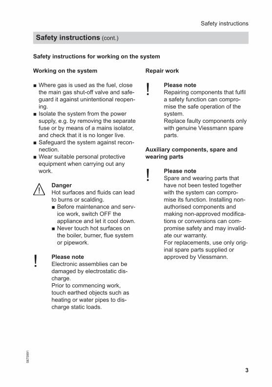
Safety instructions for working on the system
Working on the system
■ Where gas is used as the fuel, closethe main gas shut-off valve and safe-guard it against unintentional reopen-ing.
■ Isolate the system from the powersupply, e.g. by removing the separatefuse or by means of a mains isolator,and check that it is no longer live.
■ Safeguard the system against recon-nection.
■ Wear suitable personal protectiveequipment when carrying out anywork.
DangerHot surfaces and fluids can leadto burns or scalding.■ Before maintenance and serv-
ice work, switch OFF theappliance and let it cool down.
■ Never touch hot surfaces onthe boiler, burner, flue systemor pipework.
! Please noteElectronic assemblies can bedamaged by electrostatic dis-charge.Prior to commencing work,touch earthed objects such asheating or water pipes to dis-charge static loads.
Repair work
! Please noteRepairing components that fulfila safety function can compro-mise the safe operation of thesystem.Replace faulty components onlywith genuine Viessmann spareparts.
Auxiliary components, spare andwearing parts
! Please noteSpare and wearing parts thathave not been tested togetherwith the system can compro-mise its function. Installing non-authorised components andmaking non-approved modifica-tions or conversions can com-promise safety and may invalid-ate our warranty.For replacements, use only orig-inal spare parts supplied orapproved by Viessmann.
Safety instructions
Safety instructions (cont.)
5675
991

4
Safety instructions for operating the system
If you smell gas
DangerEscaping gas can lead to explo-sions which may result in seri-ous injury.■ Do not smoke. Prevent naked
flames and sparks. Neverswitch lights or electrical appli-ances on or off.
■ Close the gas shut-off valve.■ Open windows and doors.■ Evacuate any people from the
danger zone.■ Notify your gas or electricity
supply utility from outside thebuilding.
■ Have the power supply to thebuilding shut off from a safeplace (outside the building).
If you smell flue gas
DangerFlue gas can lead to life threat-ening poisoning.■ Shut down the heating sys-
tem.■ Ventilate the installation site.■ Close doors to living spaces
to prevent flue gases fromspreading.
What to do if water escapes from theappliance
DangerIf water escapes from the appli-ance there is a risk of electrocu-tion.Switch OFF the heating systemat the external isolator (e.g. fusebox, domestic distributionboard).
DangerIf water escapes from the appli-ance there is a risk of scalding.Never touch hot heating water.
Condensate
DangerContact with condensate can beharmful to health.Never let condensate touch yourskin or eyes and do not swallowit.
Flue systems and combustion air
Ensure that flue systems are clear andcannot be sealed, for instance due toaccumulation of condensate or otherexternal causes.Ensure an adequate supply of combus-tion air.Inform system users that subsequentmodifications to the building character-istics are not permissible (e.g. cable/pipework routing, cladding or parti-tions).
Safety instructions
Safety instructions (cont.)
5675
991

5
DangerLeaking or blocked flue sys-tems, or an inadequate supplyof combustion air can cause lifethreatening poisoning from car-bon monoxide in the flue gas.Ensure the flue system is ingood working order. Vents forsupplying combustion air mustbe non-sealable.
Extractors
Operating appliances that exhaust airto the outside (extractor hoods, extrac-tors, air conditioning units, etc.) cancreate negative pressure. If the boiler isoperated at the same time, this canlead to a reverse flow of flue gas.
DangerThe simultaneous operation ofthe boiler and appliances thatexhausts air to the outside canresult in life threatening poison-ing due to a reverse flow of fluegas.Fit an interlock circuit or takesuitable steps to ensure an ade-quate supply of combustion air.
Safety instructions
Safety instructions (cont.)
5675
991

6
Installation instructionsInformationDisposal of packaging.......................................................................................... 8Symbols................................................................................................................ 9Intended use......................................................................................................... 10Product information.............................................................................................. 10
Preparing for installation................................................................................... 13
Installation sequenceMounting the boiler and making connections....................................................... 17Opening the programming unit............................................................................. 22Electrical connections........................................................................................... 23
Service instructionsCommissioning, inspection, maintenanceSteps - commissioning, inspection and maintenance.......................................... 26Further details regarding the individual steps....................................................... 27
TroubleshootingFunction sequence and possible faults................................................................ 51Fault display......................................................................................................... 52Repairs................................................................................................................. 57
Changing the gas typeConverting from LPG to natural gas..................................................................... 68
Control unitFunctions and operating conditions in weather-compensated mode................... 70
DesignsConnection and wiring diagrams.......................................................................... 72
Parts listsOverview of assemblies....................................................................................... 77Casing assembly.................................................................................................. 80Heat cell assembly............................................................................................... 82Burner assembly.................................................................................................. 84Hydraulic assembly.............................................................................................. 86Grundfos hydraulic assembly............................................................................... 88Control unit assembly........................................................................................... 90Miscellaneous assembly...................................................................................... 92
Index
Index
5675
991

7
Specification....................................................................................................... 93
DisposalFinal decommissioning and disposal.................................................................... 94
CertificatesDeclaration of conformity...................................................................................... 95
Keyword index.................................................................................................... 96
Index
Index (cont.)
5675
991

8
Please dispose of packaging waste inline with statutory regulations.
Information
Disposal of packaging
5675
991
9
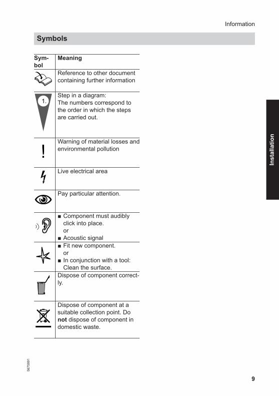
Sym-bol
Meaning
Reference to other documentcontaining further information
1.Step in a diagram:The numbers correspond tothe order in which the stepsare carried out.
Warning of material losses andenvironmental pollution Live electrical area Pay particular attention. ■ Component must audibly
click into place.or
■ Acoustic signal■ Fit new component.
or■ In conjunction with a tool:
Clean the surface.Dispose of component correct-ly. Dispose of component at asuitable collection point. Donot dispose of component indomestic waste.
Information
Symbols56
7599
1
Inst
alla
tion

10
The appliance is intended solely forinstallation and operation in sealedunvented heating systems that complywith EN 12828, with due attention paidto the associated installation, serviceand operating instructions. It is onlydesigned for heating up heating waterthat is of potable water quality.
Intended use presupposes that a fixedinstallation in conjunction with permissi-ble, system-specific components hasbeen carried out.
Commercial or industrial usage for apurpose other than heating the buildingor DHW shall be deemed inappropriate.
Any usage beyond this must beapproved by the manufacturer in eachindividual case.
Incorrect usage or operation of theappliance (e.g. the appliance beingopened by the system user) is prohibi-ted and will result in an exclusion of lia-bility. Incorrect usage also occurs if thecomponents in the heating system aremodified from their intended use (e.g. ifthe flue gas and ventilation air pathsare sealed).
Product information
Vitodens 050-W, type BPJD
Preset for operation with natural gas.Conversion to LPG P requires a gasconversion kit.
Gas Council No.■ 29 kW combi: 47 819 38■ 35 kW combi: 47 819 39
Conversion for other countries
The Vitodens 050-W may generallyonly be delivered to countries listed onthe type plate. For deliveries to othercountries, approved contractors mustarrange individual approval on theirown initiative and in accordance withthe law of the country in question.
Product description
The Vitodens 050-W is available as agas condensing combi boiler with inte-gral plate heat exchanger for DHWheating. For the connection of heatingcircuits and the DHW line, seepage 16 onwards.The Vitodens 050-W is set up for oper-ation with a constant boiler water tem-perature.The appliance is equipped with asealed unvented hydraulic system with2 connections for the heating flow andreturn and 2 connections for DHWheating.
Information
Intended use
5675
991
11
The following components are integra-ted into the hydraulic system:■ Circulation pump■ 3-way diverter valve■ Safety valve■ Diaphragm expansion vessel■ Plate heat exchanger for DHW heat-
ing
Connecting accessories
A time switch (accessories) can be con-nected to the control unit with a lowvoltage supply.
Siting
Suitable siting locations include:■ Recreational rooms and other living
spaces■ Ancillary rooms without their own
ventilation
■ Cupboards (open at the top)■ Recesses without compulsory clear-
ance towards combustible materials■ Attic rooms (pitched attics and long
panes) where the balanced flue pipecan be routed directly through theroof
Since the flue pipe connection for roomsealed operation is surrounded by com-bustion air (coaxial pipe), no clearancestowards combustible materials need bemaintained. For further details, see thetechnical guide on flue systems for theVitodens.The installation room must be safe fromthe risk of frost.
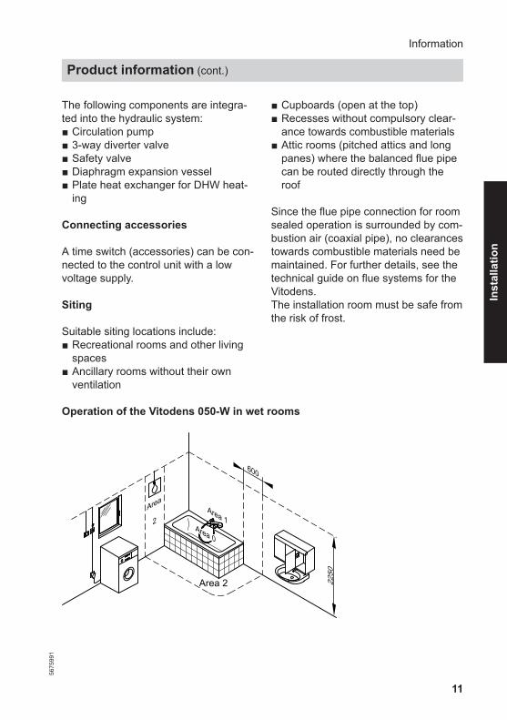
Operation of the Vitodens 050-W in wet rooms
Area 0
Area 1Area
2
Area 2
600
2250
Information
Product information (cont.)
5675
991
Inst
alla
tion

12
The Vitodens is approved for installa-tion in wet rooms (e.g. bathroom orshower rooms) (protection IP X4 D,splashproof).When installing the Vitodens in wetrooms, observe the safety zones andminimum wall clearances according toVDE 0100 [or local regulations] (seealso "Electrical safety zone"). TheVitodens may be installed in safetyzone 1 if hosed water (e.g. from mas-sage showers) is prevented.
Electrical equipment in rooms contain-ing a bathtub or a shower must beinstalled in such a way that users can-not be exposed to dangerous body cur-rents.VDE 0100 specifies that cables supply-ing permanently installed consumers inzones 1 and 2 should only be run verti-cally and routed into the equipmentfrom the back.
Information
Product information (cont.)
5675
991
13
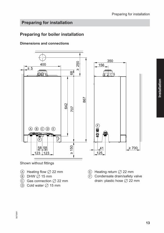
Preparing for boiler installation
Dimensions and connections
41
5
250
400
58 58123123
BA C E
F
D
156350
125
867
6870
715
064
2
F
700
Shown without fittings
A Heating flow 7 22 mmB DHW 7 15 mmC Gas connection 7 22 mmD Cold water 7 15 mm
E Heating return 7 22 mmF Condensate drain/safety valve
drain: plastic hose 7 22 mm
Preparing for installation
Preparing for installation56
7599
1
Inst
alla
tion
14
Minimum clearances
Maintain a clearance of 700 mm in frontof the Vitodens for maintenance purpo-ses. Maintenance clearances to the l.h.or r.h. side of the Vitodens are notrequired.
Preparing for installation
Preparing for installation (cont.)
5675
991

15
Fitting the wall mounting bracket
250
A
Ø10 145
A Vitodens installation template
Preparing for installation
Preparing for installation (cont.)
5675
991
Inst
alla
tion
16
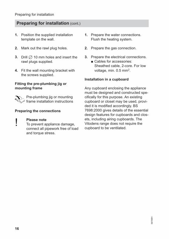
1. Position the supplied installationtemplate on the wall.
2. Mark out the rawl plug holes.
3. Drill 7 10 mm holes and insert therawl plugs supplied.
4. Fit the wall mounting bracket withthe screws supplied.
Fitting the pre-plumbing jig ormounting frame
Pre-plumbing jig or mountingframe installation instructions
Preparing the connections
! Please noteTo prevent appliance damage,connect all pipework free of loadand torque stress.
1. Prepare the water connections.Flush the heating system.
2. Prepare the gas connection.
3. Prepare the electrical connections.■ Cables for accessories:
Sheathed cable, 2-core. For lowvoltage, min. 0.5 mm2.
Installation in a cupboard
Any cupboard enclosing the appliancemust be designed and constructed spe-cifically for this purpose. An existingcupboard or closet may be used, provi-ded it is modified accordingly. BS7698:2000 gives details of the essentialdesign features for cupboards and clos-ets, including airing cupboards. TheVitodens range does not require thecupboard to be ventilated.
Preparing for installation
Preparing for installation (cont.)
5675
991
17
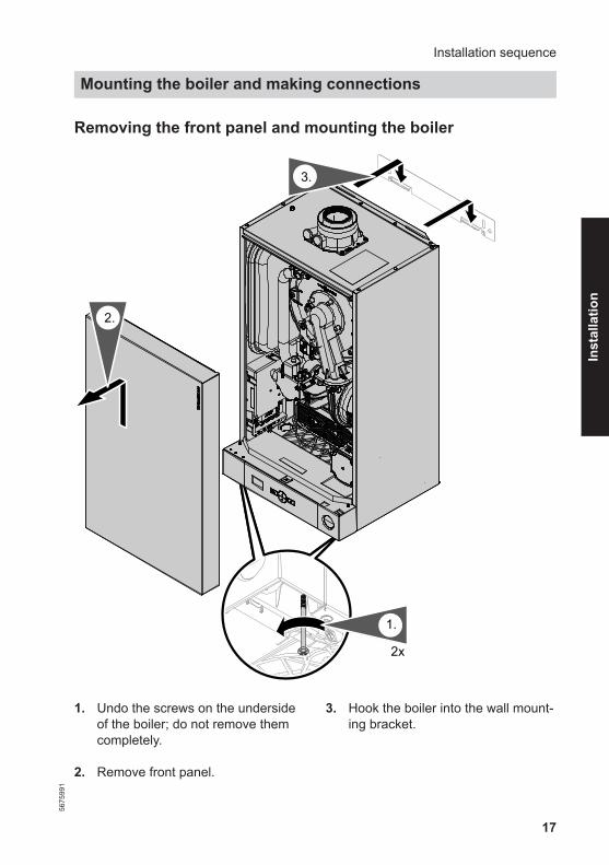
Removing the front panel and mounting the boiler
2x
1.
2.
3.
1. Undo the screws on the undersideof the boiler; do not remove themcompletely.
2. Remove front panel.
3. Hook the boiler into the wall mount-ing bracket.
Installation sequence
Mounting the boiler and making connections56
7599
1
Inst
alla
tion
18
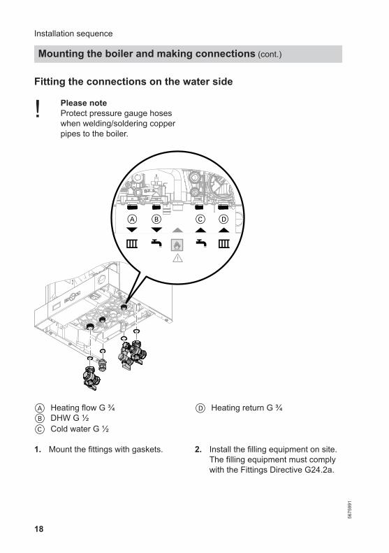
Fitting the connections on the water side
! Please noteProtect pressure gauge hoses when welding/soldering copperpipes to the boiler.
A
¨
z z
B C D
A Heating flow G ¾B DHW G ½C Cold water G ½
D Heating return G ¾
1. Mount the fittings with gaskets. 2. Install the filling equipment on site. The filling equipment must complywith the Fittings Directive G24.2a.
Installation sequence
Mounting the boiler and making connections (cont.)
5675
991
19
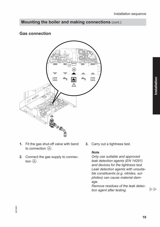
Gas connection
A
¨
z z1. Fit the gas shut-off valve with bend
to connection A.
2. Connect the gas supply to connec-tion A.
3. Carry out a tightness test.
NoteOnly use suitable and approvedleak detection agents (EN 14291)and devices for the tightness test.Leak detection agents with unsuita-ble constituents (e.g. nitrides, sul-phides) can cause material dam-age.Remove residues of the leak detec-tion agent after testing.
Installation sequence
Mounting the boiler and making connections (cont.)
5675
991
Inst
alla
tion

20
! Please noteExcessive test pressure willdamage the boiler and thegas train. Max. test pressure 150 mbar(15 kPa). Where higherpressure is required fortightness tests, disconnectthe boiler and the gas trainfrom the main supply pipe(undo the fitting).
4. Purge the gas line.
Connecting the safety valve and condensate drain
A
■ The condensate pipe is connected tothe discharge pipe of the safetyvalve. The condensate hose suppliedmeets the temperature requirementsthat are part of the CE certification.
■ We recommend connecting the con-densate pipe to the internal domesticwaste water system, either directly orvia a tundish.
■ If the condensate pipe is routed out-side the building, use a pipe with min.7 30 mm and protect the pipe fromfrost. Avoid long external pipe runs.Install a tundish.
! Please noteA frozen condensate pipe canresult in faults and damage tothe boiler.Always protect condensatepipes against frost.
■ Observe local building regulations.Connect condensate pipe A to thepublic sewage system with a constantfall and a pipe vent.Observe local waste water regulations.
NoteFill the trap with water before commis-sioning.
Installation sequence
Mounting the boiler and making connections (cont.)
5675
991

21
Filling the trap with water
Pour at least 0.3 l of water into the fluegas connection.
! Please noteDuring commissioning, flue gasmay escape from the conden-sate drain.Always fill the trap with waterbefore commissioning.
Balanced flue connection
Connect the balanced flue pipe.During installation and positioning ofthe flue system, observe Part J of theBuilding Regulations and BS 5440.
Flue system installation instruc-tions
Connecting several Vitodens 050-Wto a shared flue system
Adjust the burner settings of each con-nected boiler to match the flue system.See page 34.
Do not carry out commissioning untilthe following conditions are met:■ Free passage through the flue gas
pipes.■ Flue system with positive pressure is
gas-tight.■ Inspection port covers checked for
secure and tight seating.
■ Apertures for ensuring sufficient com-bustion air supply are open and can-not be closed off.
■ Applicable regulations on installingand commissioning flue systemshave been followed.
Installation sequence
Mounting the boiler and making connections (cont.)
5675
991
Inst
alla
tion

22
DangerLeaking or blocked flue systemsor an insufficient supply of com-bustion air cause life threateningpoisoning due to carbon monox-ide in the flue gas.
Ensure the flue system functionscorrectly. Apertures for combus-tion air supply must not be ableto be closed off.Prevent condensate drainagevia a wind protector.
Opening the programming unit
Only required if a wireless receiver ortime switch (accessories) is to be con-nected.
1.
3.
2. 2x
! Please noteElectronic assemblies can bedamaged by electrostatic dis-charge.
Prior to commencing any work,touch earthed objects such asheating or water pipes to dis-charge static loads.
Installation sequence
Mounting the boiler and making connections (cont.)
5675
991
23
B
C
4 3 2 1A
OT+OT-
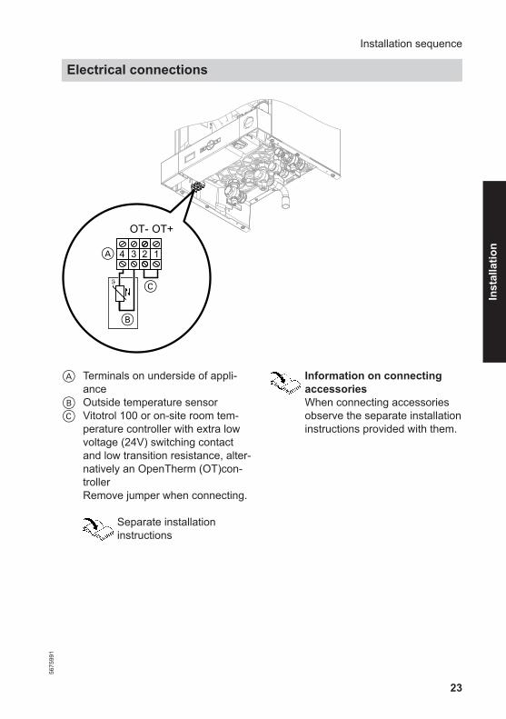
A Terminals on underside of appli-ance
B Outside temperature sensorC Vitotrol 100 or on-site room tem-
perature controller with extra lowvoltage (24V) switching contactand low transition resistance, alter-natively an OpenTherm (OT)con-trollerRemove jumper when connecting.
Separate installationinstructions
Information on connectingaccessoriesWhen connecting accessoriesobserve the separate installationinstructions provided with them.
Installation sequence
Electrical connections56
7599
1
Inst
alla
tion
24
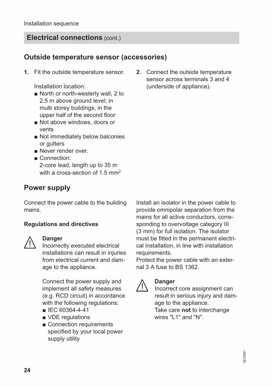
Outside temperature sensor (accessories)
1. Fit the outside temperature sensor.
Installation location:■ North or north-westerly wall, 2 to
2.5 m above ground level; inmulti storey buildings, in theupper half of the second floor
■ Not above windows, doors orvents
■ Not immediately below balconiesor gutters
■ Never render over.■ Connection:
2-core lead, length up to 35 mwith a cross-section of 1.5 mm2
2. Connect the outside temperaturesensor across terminals 3 and 4(underside of appliance).
Power supply
Connect the power cable to the buildingmains.
Regulations and directives
DangerIncorrectly executed electricalinstallations can result in injuriesfrom electrical current and dam-age to the appliance.
Connect the power supply andimplement all safety measures(e.g. RCD circuit) in accordancewith the following regulations:■ IEC 60364-4-41■ VDE regulations■ Connection requirements
specified by your local powersupply utility
Install an isolator in the power cable toprovide omnipolar separation from themains for all active conductors, corre-sponding to overvoltage category III(3 mm) for full isolation. The isolatormust be fitted in the permanent electri-cal installation, in line with installationrequirements.Protect the power cable with an exter-nal 3 A fuse to BS 1362.
DangerIncorrect core assignment canresult in serious injury and dam-age to the appliance.Take care not to interchangewires "L1" and "N".
Installation sequence
Electrical connections (cont.)
5675
991
25
DangerThe absence of componentearthing can lead to seriousinjury from electric current if anelectrical fault occurs.
The appliance and pipeworkmust be connected to the equi-potential bonding of the building.
Routing connecting cables/leads
! Please noteConnecting cables/leads will bedamaged if they touch hot com-ponents.
When routing and securingcables/leads on site, ensure thatthe maximum permissible tem-perature for these is not excee-ded.
Installation sequence
Electrical connections (cont.)
5675
991
Inst
alla
tion

26
For further information regarding the individual steps, see the page indicated
Commissioning steps
Inspection steps
Maintenance steps Page
• • • 1. Filling the heating system.............................................. 27
• • • 2. Draining the heating system.......................................... 29
• • • 3. Converting to operation with LPG................................ 30
• • • 4. Checking the static pressure and supply pressure.... 30
• 5. Reducing the maximum heating output....................... 32
• 6. Matching the burner output to the flue system........... 33
• 7. Burner adjustment when connecting multiple fluesto a shared flue system.................................................. 34
• 8. Checking the CO2 content............................................. 38
• • 9. Removing the burner ..................................................... 42
• • 10. Checking the burner gasket and burner gauzeassembly......................................................................... 42
• • 11. Checking and adjusting the electrode.......................... 44
• • 12. Cleaning the heat exchanger......................................... 45
• • 13. Checking the condensate drain and cleaning thetrap................................................................................... 46
• • 14. Installing the burner ...................................................... 47
• • 15. Checking the diaphragm expansion vessel andsystem pressure............................................................. 48
• • • 16. Checking all connections on the heating water andDHW sides for leaks
• • • 17. Checking the firm seating of electrical connections • • • 18. Checking all gas equipment for tightness at
operating pressure ........................................................ 48
• • 19. Fitting the front panel..................................................... 49
• 20. Instructing the system user........................................... 50
Commissioning, inspection, maintenance
Steps - commissioning, inspection and maintenance
5675
991

27
Filling the heating system
! Please noteUnsuitable fill water increasesthe level of deposits and corro-sion and may lead to boilerdamage.■ Flush the heating system thor-
oughly before filling.■ Only fill with water of potable
quality.
■ Fill water with a hardnessabove 300 ppm must be soft-ened.
■ Special antifreeze suitable forheating systems can beadded to the fill water.
1. Close the gas shut-off valve.
2. Turn on the power supply atON/OFF switch A.
3. Activate the filling function.1. Press MODE and simultane-
ously and hold for approx. 3 s."SERV" is displayed and "1"flashes.
2. OK to confirm."0" flashes on the display.
3. Use / to set "I"4. OK to confirm.
The filling function is active.
NoteThe function is terminated by reset-ting the value to "0" or by turningoff the ON/OFF switch.The function will terminate automat-ically after 30 min.
Commissioning, inspection, maintenance
Further details regarding the individual steps56
7599
1
Serv
ice

28
B C
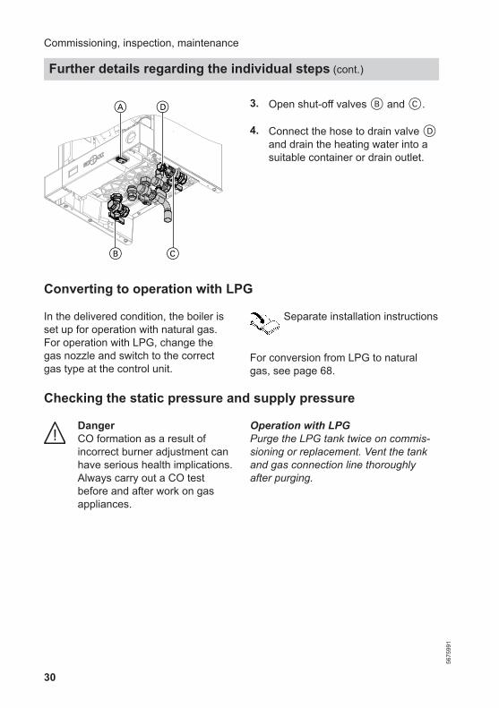
A 4. Open shut-off valves B and C.
Commissioning, inspection, maintenance
Further details regarding the individual steps (cont.)
5675
991

29
5. Fill and vent the heating systemusing the on-site valve. Systempressure 0.8 to 1.2 bar(0.08 to 0.1 MPa). The system can be filled using aseparate filling point fitted at a con-venient position in the heating cir-cuit. The connection must beremoved when filling is complete.Where local water authority regula-tions do not allow temporary con-nections, a sealed system fillerpump with break tank must beused. The heating system will notbe filled automatically from thedomestic hot water side. Alternativemethods for filling sealed systemsare provided in BS 5449.
Draining the heating system
! Please noteRisk of scalding
Only drain the boiler or heatingsystem when the boiler watertemperature has dropped below40 °C.
1. Close the gas shut-off valve.
2. Turn off the power supply atON/OFF switch A.
Commissioning, inspection, maintenance
Further details regarding the individual steps (cont.)
5675
991
Serv
ice
30
B C
A D 3. Open shut-off valves B and C.
4. Connect the hose to drain valve Dand drain the heating water into asuitable container or drain outlet.
Converting to operation with LPG
In the delivered condition, the boiler isset up for operation with natural gas.For operation with LPG, change thegas nozzle and switch to the correctgas type at the control unit.
Separate installation instructions
For conversion from LPG to naturalgas, see page 68.
Checking the static pressure and supply pressure
DangerCO formation as a result ofincorrect burner adjustment canhave serious health implications.Always carry out a CO testbefore and after work on gasappliances.
Operation with LPGPurge the LPG tank twice on commis-sioning or replacement. Vent the tankand gas connection line thoroughlyafter purging.
Commissioning, inspection, maintenance
Further details regarding the individual steps (cont.)
5675
991
31
A
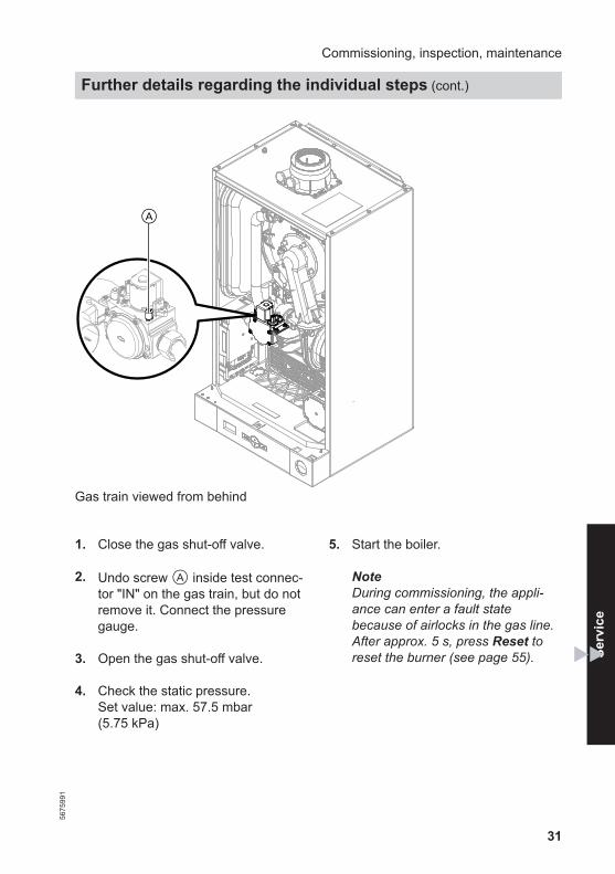
Gas train viewed from behind
1. Close the gas shut-off valve.
2. Undo screw A inside test connec-tor "IN" on the gas train, but do notremove it. Connect the pressuregauge.
3. Open the gas shut-off valve.
4. Check the static pressure.Set value: max. 57.5 mbar(5.75 kPa)
5. Start the boiler.
NoteDuring commissioning, the appli-ance can enter a fault statebecause of airlocks in the gas line.After approx. 5 s, press Reset toreset the burner (see page 55).
Commissioning, inspection, maintenance
Further details regarding the individual steps (cont.)
5675
991
Serv
ice
32
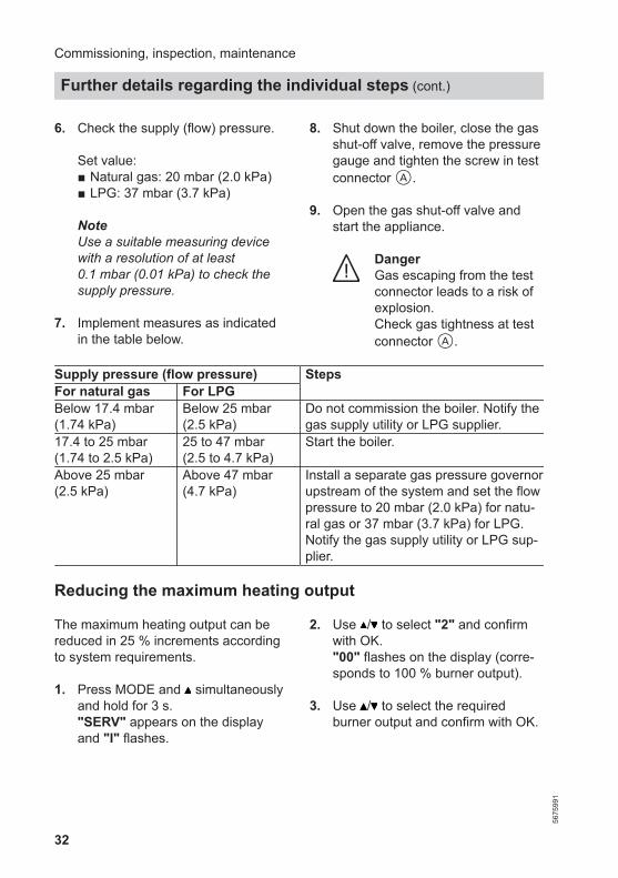
6. Check the supply (flow) pressure.
Set value:■ Natural gas: 20 mbar (2.0 kPa)■ LPG: 37 mbar (3.7 kPa)
NoteUse a suitable measuring devicewith a resolution of at least0.1 mbar (0.01 kPa) to check thesupply pressure.
7. Implement measures as indicatedin the table below.
8. Shut down the boiler, close the gasshut-off valve, remove the pressuregauge and tighten the screw in testconnector A.
9. Open the gas shut-off valve andstart the appliance.
DangerGas escaping from the testconnector leads to a risk ofexplosion.Check gas tightness at testconnector A.
Supply pressure (flow pressure) StepsFor natural gas For LPGBelow 17.4 mbar(1.74 kPa)
Below 25 mbar(2.5 kPa)
Do not commission the boiler. Notify thegas supply utility or LPG supplier.
17.4 to 25 mbar(1.74 to 2.5 kPa)
25 to 47 mbar(2.5 to 4.7 kPa)
Start the boiler.
Above 25 mbar(2.5 kPa)
Above 47 mbar(4.7 kPa)
Install a separate gas pressure governorupstream of the system and set the flowpressure to 20 mbar (2.0 kPa) for natu-ral gas or 37 mbar (3.7 kPa) for LPG.Notify the gas supply utility or LPG sup-plier.
Reducing the maximum heating output
The maximum heating output can bereduced in 25 % increments accordingto system requirements.
1. Press MODE and simultaneouslyand hold for 3 s."SERV" appears on the displayand "I" flashes.
2. Use / to select "2" and confirmwith OK."00" flashes on the display (corre-sponds to 100 % burner output).
3. Use / to select the requiredburner output and confirm with OK.
Commissioning, inspection, maintenance
Further details regarding the individual steps (cont.)
5675
991
33
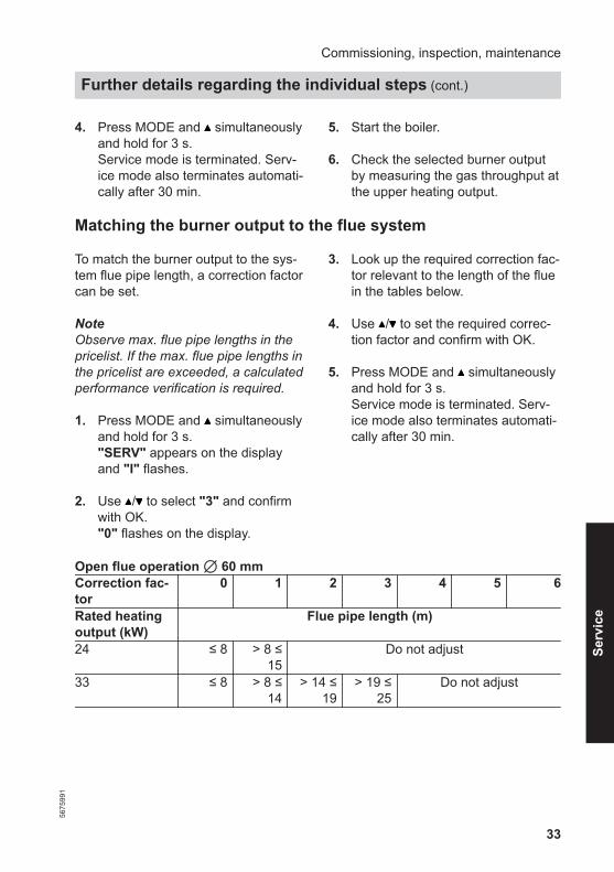
4. Press MODE and simultaneouslyand hold for 3 s.Service mode is terminated. Serv-ice mode also terminates automati-cally after 30 min.
5. Start the boiler.
6. Check the selected burner outputby measuring the gas throughput atthe upper heating output.
Matching the burner output to the flue system
To match the burner output to the sys-tem flue pipe length, a correction factorcan be set.
NoteObserve max. flue pipe lengths in thepricelist. If the max. flue pipe lengths inthe pricelist are exceeded, a calculatedperformance verification is required.
1. Press MODE and simultaneouslyand hold for 3 s."SERV" appears on the displayand "I" flashes.
2. Use / to select "3" and confirmwith OK."0" flashes on the display.
3. Look up the required correction fac-tor relevant to the length of the fluein the tables below.
4. Use / to set the required correc-tion factor and confirm with OK.
5. Press MODE and simultaneouslyand hold for 3 s.Service mode is terminated. Serv-ice mode also terminates automati-cally after 30 min.
Open flue operation 7 60 mmCorrection fac-tor
0 1 2 3 4 5 6
Rated heatingoutput (kW)
Flue pipe length (m)
24 ≤ 8 > 8 ≤15
Do not adjust
33 ≤ 8 > 8 ≤14
> 14 ≤19
> 19 ≤25
Do not adjust
Commissioning, inspection, maintenance
Further details regarding the individual steps (cont.)
5675
991
Serv
ice
34
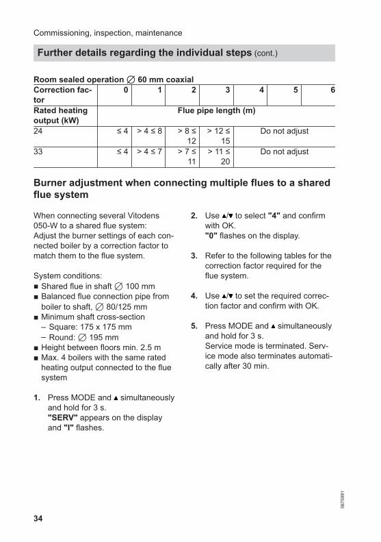
Room sealed operation 7 60 mm coaxialCorrection fac-tor
0 1 2 3 4 5 6
Rated heatingoutput (kW)
Flue pipe length (m)
24 ≤ 4 > 4 ≤ 8 > 8 ≤12
> 12 ≤15
Do not adjust
33 ≤ 4 > 4 ≤ 7 > 7 ≤11
> 11 ≤20
Do not adjust
Burner adjustment when connecting multiple flues to a sharedflue system
When connecting several Vitodens050-W to a shared flue system: Adjust the burner settings of each con-nected boiler by a correction factor tomatch them to the flue system.
System conditions:■ Shared flue in shaft 7 100 mm■ Balanced flue connection pipe from
boiler to shaft, 7 80/125 mm■ Minimum shaft cross-section
– Square: 175 x 175 mm– Round: 7 195 mm
■ Height between floors min. 2.5 m■ Max. 4 boilers with the same rated
heating output connected to the fluesystem
1. Press MODE and simultaneouslyand hold for 3 s."SERV" appears on the displayand "I" flashes.
2. Use / to select "4" and confirmwith OK."0" flashes on the display.
3. Refer to the following tables for thecorrection factor required for theflue system.
4. Use / to set the required correc-tion factor and confirm with OK.
5. Press MODE and simultaneouslyand hold for 3 s.Service mode is terminated. Serv-ice mode also terminates automati-cally after 30 min.
Commissioning, inspection, maintenance
Further details regarding the individual steps (cont.)
5675
991
35
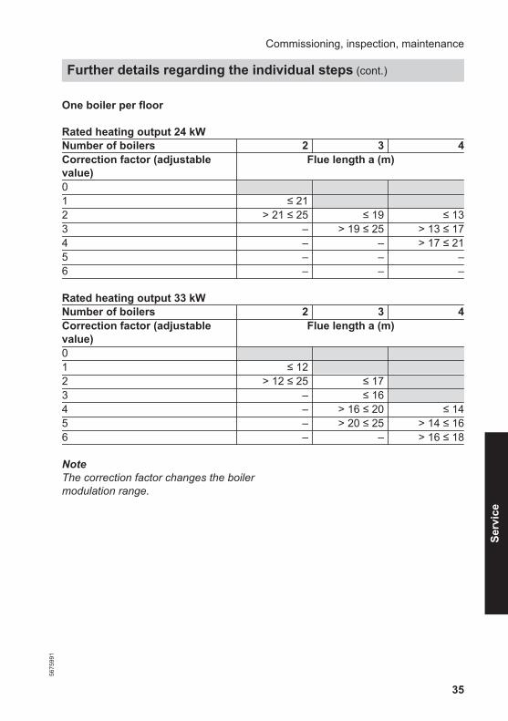
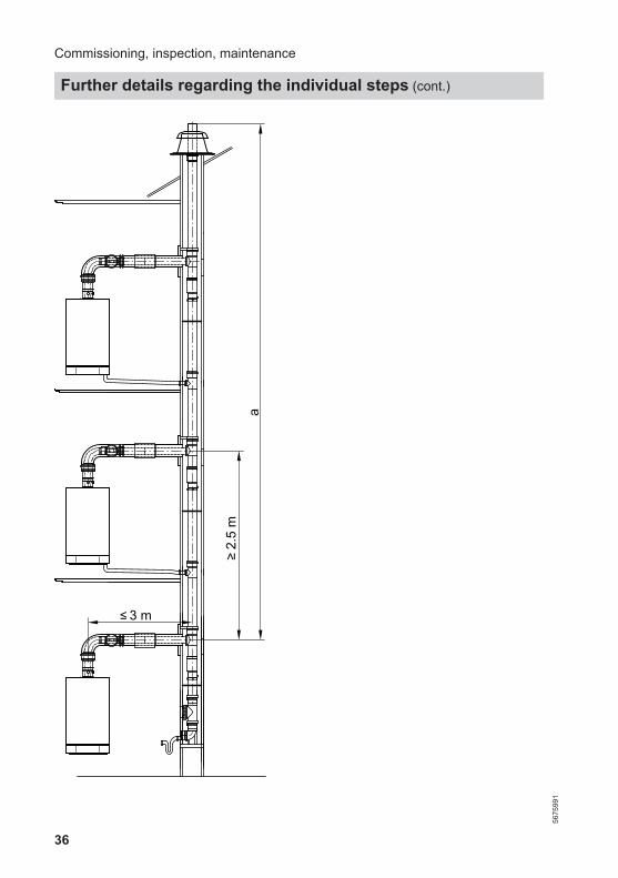
One boiler per floor
Rated heating output 24 kWNumber of boilers 2 3 4Correction factor (adjustablevalue)
Flue length a (m)
01 ≤ 212 > 21 ≤ 25 ≤ 19 ≤ 133 – > 19 ≤ 25 > 13 ≤ 174 – – > 17 ≤ 215 – – –6 – – –
Rated heating output 33 kWNumber of boilers 2 3 4Correction factor (adjustablevalue)
Flue length a (m)
01 ≤ 122 > 12 ≤ 25 ≤ 173 – ≤ 164 – > 16 ≤ 20 ≤ 145 – > 20 ≤ 25 > 14 ≤ 166 – – > 16 ≤ 18
NoteThe correction factor changes the boilermodulation range.
Commissioning, inspection, maintenance
Further details regarding the individual steps (cont.)
5675
991
Serv
ice
36
3 m
a
2.5
m
Commissioning, inspection, maintenance
Further details regarding the individual steps (cont.)
5675
991
37
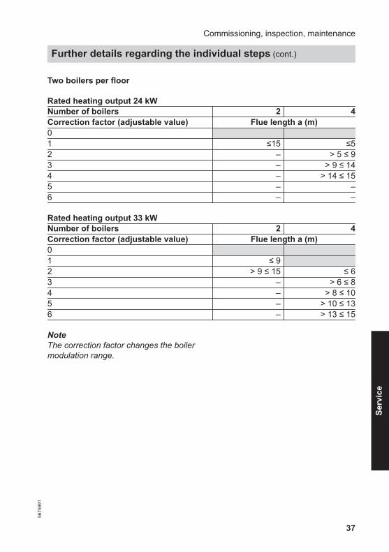
Two boilers per floor
Rated heating output 24 kWNumber of boilers 2 4Correction factor (adjustable value) Flue length a (m)01 ≤15 ≤52 – > 5 ≤ 93 – > 9 ≤ 144 – > 14 ≤ 155 – –6 – –
Rated heating output 33 kWNumber of boilers 2 4Correction factor (adjustable value) Flue length a (m)01 ≤ 92 > 9 ≤ 15 ≤ 63 – > 6 ≤ 84 – > 8 ≤ 105 – > 10 ≤ 136 – > 13 ≤ 15
NoteThe correction factor changes the boilermodulation range.
Commissioning, inspection, maintenance
Further details regarding the individual steps (cont.)
5675
991
Serv
ice
38
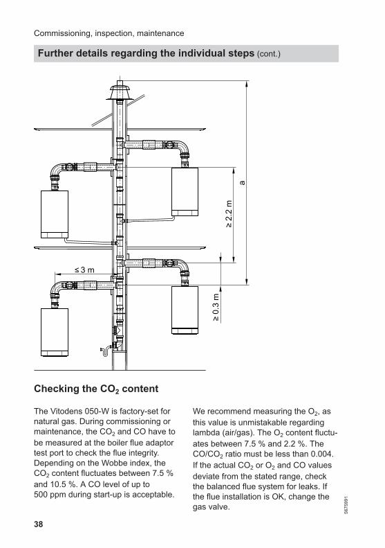
3 m
0.3
m2.
2 m
a
Checking the CO2 content
The Vitodens 050-W is factory-set fornatural gas. During commissioning ormaintenance, the CO2 and CO have tobe measured at the boiler flue adaptortest port to check the flue integrity.Depending on the Wobbe index, theCO2 content fluctuates between 7.5 %and 10.5 %. A CO level of up to500 ppm during start-up is acceptable.
We recommend measuring the O2, asthis value is unmistakable regardinglambda (air/gas). The O2 content fluctu-ates between 7.5 % and 2.2 %. TheCO/CO2 ratio must be less than 0.004.If the actual CO2 or O2 and CO valuesdeviate from the stated range, checkthe balanced flue system for leaks. Ifthe flue installation is OK, change thegas valve.
Commissioning, inspection, maintenance
Further details regarding the individual steps (cont.)
5675
991
39
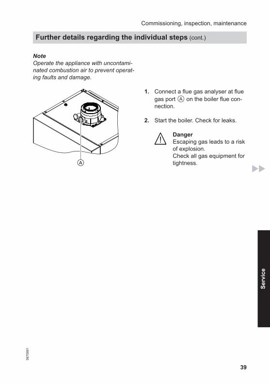
NoteOperate the appliance with uncontami-nated combustion air to prevent operat-ing faults and damage.
A
1. Connect a flue gas analyser at fluegas port A on the boiler flue con-nection.
2. Start the boiler. Check for leaks.
DangerEscaping gas leads to a riskof explosion.Check all gas equipment fortightness.
Commissioning, inspection, maintenance
Further details regarding the individual steps (cont.)
5675
991
Serv
ice

40
3. To check the CO2 content theburner output can be adjusted man-ually.1. Press MODE.2. / repeatedly until "SERV" is
displayed.3. OK to confirm.
"OFF" appears on the display.4. Use / to adjust the burner out-
put:
Shown on display
Burner out-put
_ 20 20 %_ _ 40 40 %_ _ _ 60 60 %_ _ _ _ 80 80 %_ _ _ _ _ 00 100 %
5. Confirm your setting with OK.
NoteThis function terminates automati-cally after 30 min; alternatively use/ to set the burner output to
"OFF" after the test.
4. Set the upper heating output andcheck the CO2 content.The CO2 content must be within thefollowing range for the respectivegas type. See table.
Gas type CO2 contentin %
E or H (G20) 7.5 – 10.5P (G31) 10.0 – 12.0
Commissioning, inspection, maintenance
Further details regarding the individual steps (cont.)
5675
991
41
5. Set the lower heating output andcheck the CO2 content.The CO2 content must be between0.3 and 0.9 % below the value ofthe upper heating output.
6. ■ If the CO2 content is within theindicated range, continue withpoint 8.
■ If the CO2 content is not withinthe indicated range, check thebalanced flue system for tight-ness; remedy any leaks.Replace gas train if required.
7. Re-check the CO2 content for theupper and lower heating output.
8. Shut down the boiler. Remove fluegas analyser. Seal flue gas aper-ture A.
Commissioning, inspection, maintenance
Further details regarding the individual steps (cont.)
5675
991
Serv
ice
42
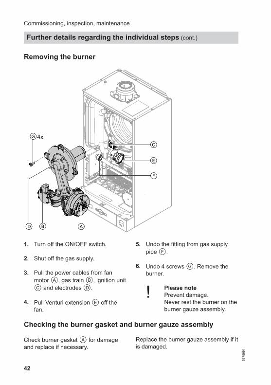
Removing the burner
4xG
C
E
F
ABD
1. Turn off the ON/OFF switch.
2. Shut off the gas supply.
3. Pull the power cables from fanmotor A, gas train B, ignition unitC and electrodes D.
4. Pull Venturi extension E off thefan.
5. Undo the fitting from gas supplypipe F.
6. Undo 4 screws G. Remove theburner.
! Please notePrevent damage. Never rest the burner on theburner gauze assembly.
Checking the burner gasket and burner gauze assembly
Check burner gasket A for damageand replace if necessary.
Replace the burner gauze assembly if itis damaged.
Commissioning, inspection, maintenance
Further details regarding the individual steps (cont.)
5675
991

43
A
C
D
E
B
1. Remove electrode B.
2. Undo 2 Torx screws. Remove ther-mal insulation ring C.
3. Undo 2 Torx screws. Removeburner gauze assembly D withgasket E.
4. Insert and secure new burnergauze assembly D with new gas-ket E.
! Please noteTighten screws enough to ensure the componentsdo not suffer damage andwill function correctly.
Commissioning, inspection, maintenance
Further details regarding the individual steps (cont.)
5675
991
Serv
ice
44
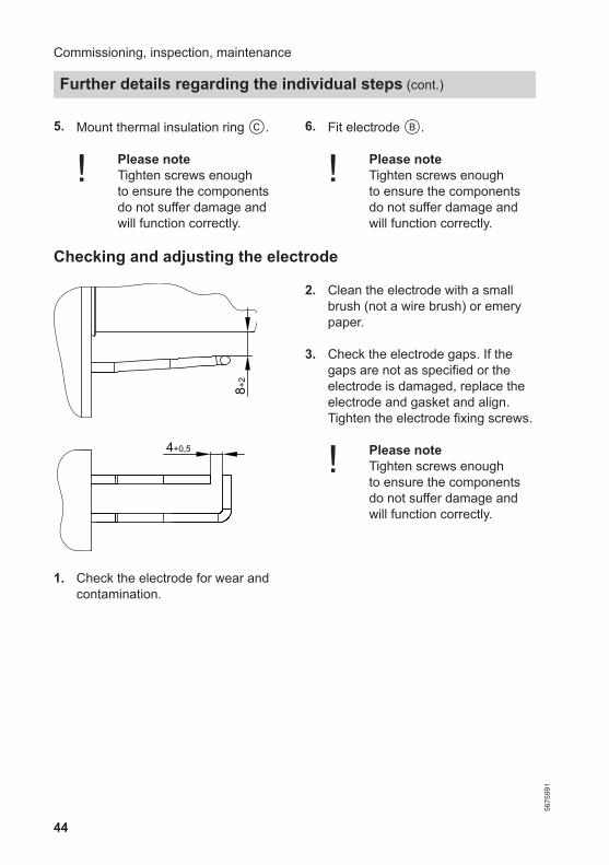
5. Mount thermal insulation ring C.
! Please noteTighten screws enough to ensure the componentsdo not suffer damage andwill function correctly.
6. Fit electrode B.
! Please noteTighten screws enough to ensure the componentsdo not suffer damage andwill function correctly.
Checking and adjusting the electrode8+
2
4+0,5
1. Check the electrode for wear andcontamination.
2. Clean the electrode with a smallbrush (not a wire brush) or emerypaper.
3. Check the electrode gaps. If thegaps are not as specified or theelectrode is damaged, replace theelectrode and gasket and align.Tighten the electrode fixing screws.
! Please noteTighten screws enough to ensure the componentsdo not suffer damage andwill function correctly.
Commissioning, inspection, maintenance
Further details regarding the individual steps (cont.)
5675
991
45
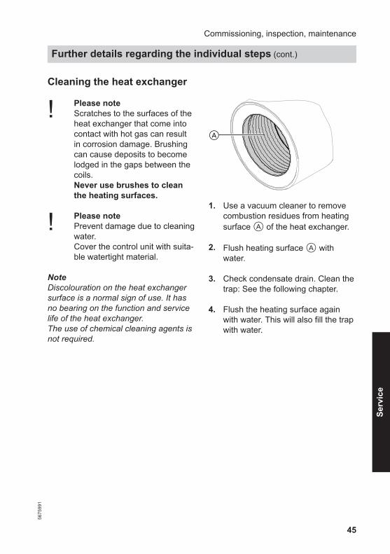
Cleaning the heat exchanger
! Please noteScratches to the surfaces of theheat exchanger that come intocontact with hot gas can resultin corrosion damage. Brushingcan cause deposits to becomelodged in the gaps between thecoils.Never use brushes to cleanthe heating surfaces.
! Please notePrevent damage due to cleaningwater.Cover the control unit with suita-ble watertight material.
NoteDiscolouration on the heat exchangersurface is a normal sign of use. It hasno bearing on the function and servicelife of the heat exchanger.The use of chemical cleaning agents isnot required.
A
1. Use a vacuum cleaner to removecombustion residues from heatingsurface A of the heat exchanger.
2. Flush heating surface A withwater.
3. Check condensate drain. Clean thetrap: See the following chapter.
4. Flush the heating surface againwith water. This will also fill the trapwith water.
Commissioning, inspection, maintenance
Further details regarding the individual steps (cont.)
5675
991
Serv
ice

46
Checking the condensate drain and cleaning the trap
AC
B
1. Unclip burner control unit A andremove. Protect against escapingcondensate.
2. Pull trap B upwards out of thedrain connection.
3. Remove supply hose C from trapB.
4. Clean trap B.
5. Refit supply hose C.
6. Refit trap B to the drain connec-tion.
7. Install burner control unit A.Check plugs for correct seating.
8. Fill trap B with water. For this,pour approx. 0.3 l of water into thecombustion chamber.
9. Check that condensate can drainfreely and that the connections aretight.
Commissioning, inspection, maintenance
Further details regarding the individual steps (cont.)
5675
991
47
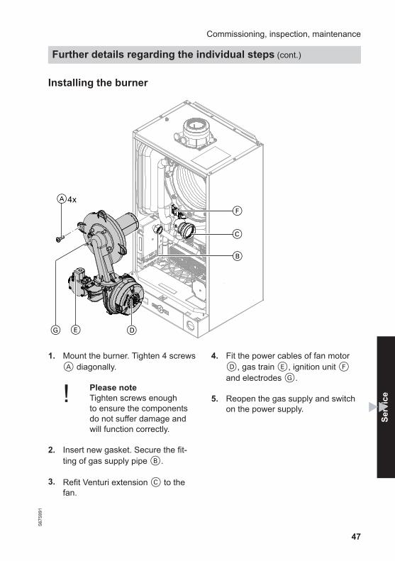
Installing the burner
4xA
F
C
B
DEG
1. Mount the burner. Tighten 4 screwsA diagonally.
! Please noteTighten screws enough to ensure the componentsdo not suffer damage andwill function correctly.
2. Insert new gasket. Secure the fit-ting of gas supply pipe B.
3. Refit Venturi extension C to thefan.
4. Fit the power cables of fan motorD, gas train E, ignition unit Fand electrodes G.
5. Reopen the gas supply and switchon the power supply.
Commissioning, inspection, maintenance
Further details regarding the individual steps (cont.)
5675
991
Serv
ice

48
6. Check the gas connections fortightness.
DangerEscaping gas leads to a riskof explosion.Check the fitting for gastightness.
! Please noteThe use of leak detectionspray can result in faultyoperation. Leak detection spray mustnot come into contact withelectrical contacts or blockthe diaphragm opening onthe gas valve.
Checking the diaphragm expansion vessel and system pres-sure
NoteThe expansion vessel can lose some ofits charge pressure over time. Whenthe boiler heats up, the pressure gaugewill indicate a higher pressure of 2 or3 bar (0.2 or 0.3 MPa). The safety valvemay also respond and discharge theexcess pressure.Therefore check the expansion vesselpre-charge pressure annually.
Check whether the installed expansionvessel is adequate for the system watervolume (GB only).Carry out this test on a cold system.
1. Drain the system until the pressuregauge shows "0".
2. If the pre-charge pressure of theexpansion vessel is lower than thestatic system pressure, top up withnitrogen until the pre-charge pres-sure is 0.1 to 0.2 bar (10 to 20 kPa)higher than the static system pres-sure.
3. Top up with water until the chargepressure of the cooled system is atleast 1.0 bar (0.1 MPa), and is 0.1to 0.2 bar (10 to 20 kPa) higherthan the pre-charge pressure of theexpansion vessel. Permiss. operating pressure: 3 bar(0.3 MPa)
Checking all gas equipment for tightness at operating pressure
DangerEscaping gas leads to a risk ofexplosion.Check all gas equipment fortightness.
! Please noteThe use of leak detection spraycan result in faulty operation. Leak detection spray must notcome into contact with electricalcontacts or block the diaphragmopening on the gas valve.
Commissioning, inspection, maintenance
Further details regarding the individual steps (cont.)
5675
991

49
Fitting the front panel
1.
2x
2.
1. Hook the front panel into place. 2. Tighten screws on the underside ofthe boiler.
Commissioning, inspection, maintenance
Further details regarding the individual steps (cont.)
5675
991
Serv
ice

50
Instructing the system user
The system installer should hand theoperating instructions to the systemuser and instruct the user in operatingthe system.
Commissioning, inspection, maintenance
Further details regarding the individual steps (cont.)
5675
991

51
Shown on display Action Control unit is-
sues a heat de-mand
No Increase set valueand ensure heat isdrawn off
Yes
Fan starts No After approx.1 min, fault F9
Check the fan, fanconnecting ca-bles, fan powersupply and fancontrol.
Yes
Ignition No Fault F4 Check the ignitionmodule connec-tion
Yes
Gas train opens No Fault F4 Check the gastrain (230 V con-trol voltage) andgas supply pres-sure
Yes
Ionisation currentbuilds (above2 µA)Symbol A
No Fault F4 Check the ionisa-tion current andelectrode adjust-ment, check thecondensate drainand check the gasline for airlocks.
Troubleshooting
Function sequence and possible faults56
7599
1
Serv
ice
52
Yes
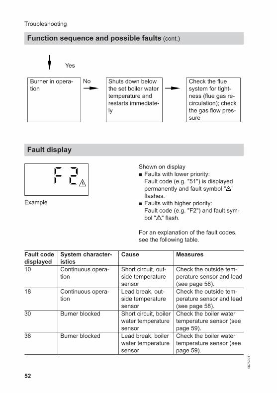
Burner in opera-tion
No Shuts down belowthe set boiler watertemperature andrestarts immediate-ly
Check the fluesystem for tight-ness (flue gas re-circulation); checkthe gas flow pres-sure
Fault display
Example
Shown on display■ Faults with lower priority:
Fault code (e.g. "51") is displayedpermanently and fault symbol " "flashes.
■ Faults with higher priority:Fault code (e.g. "F2") and fault sym-bol " " flash.
For an explanation of the fault codes,see the following table.
Fault codedisplayed
System character-istics
Cause Measures
10 Continuous opera-tion
Short circuit, out-side temperaturesensor
Check the outside tem-perature sensor and lead(see page 58).
18 Continuous opera-tion
Lead break, out-side temperaturesensor
Check the outside tem-perature sensor and lead(see page 58).
30 Burner blocked Short circuit, boilerwater temperaturesensor
Check the boiler watertemperature sensor (seepage 59).
38 Burner blocked Lead break, boilerwater temperaturesensor
Check the boiler watertemperature sensor (seepage 59).
Troubleshooting
Function sequence and possible faults (cont.)
5675
991
53
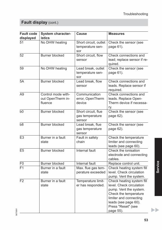
Fault codedisplayed
System character-istics
Cause Measures
51 No DHW heating Short circuit, outlettemperature sen-sor
Check the sensor (seepage 61).
52 Burner blocked Short circuit, flowsensor
Check connections andlead; replace sensor if re-quired.
59 No DHW heating Lead break, outlettemperature sen-sor
Check the sensor (seepage 61).
5A Burner blocked Lead break, flowsensor
Check connections andleads. Replace sensor ifrequired.
A9 Control mode with-out OpenTherm in-fluence
Communicationerror, OpenThermdevice
Check connections andleads. Replace Open-Therm device if necessa-ry.
b0 Burner blocked Short circuit, fluegas temperaturesensor
Check the sensor (seepage 62).
b8 Burner blocked Lead break, fluegas temperaturesensor
Check the sensor (seepage 62).
E3 Burner in a faultstate
Fault in safetychain
Check the temperaturelimiter and connectingleads (see page 60).
E5 Burner blocked Internal fault Check the ionisationelectrode and connectingcables.
F0 Burner blocked Internal fault Replace control unit.F1 Burner in a fault
stateMax. flue gas tem-perature exceeded
Check heating system filllevel. Check circulationpump. Vent the system.
F2 Burner in a faultstate
Temperature limit-er has responded.
Check heating system filllevel. Check circulationpump. Vent the system.Check the temperaturelimiter and connectingleads (see page 60).Press "Reset" (seepage 55).
Troubleshooting
Fault display (cont.)
5675
991
Serv
ice
54
Fault codedisplayed
System character-istics
Cause Measures
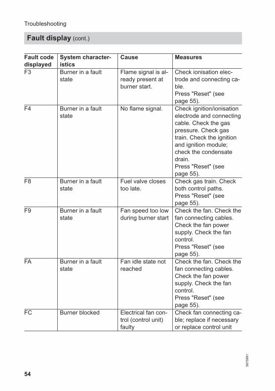
F3 Burner in a faultstate
Flame signal is al-ready present atburner start.
Check ionisation elec-trode and connecting ca-ble. Press "Reset" (seepage 55).
F4 Burner in a faultstate
No flame signal. Check ignition/ionisationelectrode and connectingcable. Check the gaspressure. Check gastrain. Check the ignitionand ignition module;check the condensatedrain.Press "Reset" (seepage 55).
F8 Burner in a faultstate
Fuel valve closestoo late.
Check gas train. Checkboth control paths.Press "Reset" (seepage 55).
F9 Burner in a faultstate
Fan speed too lowduring burner start
Check the fan. Check thefan connecting cables.Check the fan powersupply. Check the fancontrol.Press "Reset" (seepage 55).
FA Burner in a faultstate
Fan idle state notreached
Check the fan. Check thefan connecting cables.Check the fan powersupply. Check the fancontrol.Press "Reset" (seepage 55).
FC Burner blocked Electrical fan con-trol (control unit)faulty
Check fan connecting ca-ble; replace if necessaryor replace control unit
Troubleshooting
Fault display (cont.)
5675
991

55
Fault codedisplayed
System character-istics
Cause Measures
Fd Burner blocked Burner control unitfault
Check ignition electrodesand connecting cables.Check whether a stronginterference (EMC) fieldexists near the appliance.
Press "Reset" (seepage 55).Replace control unit iffault persists.
FF Burner blocked Burner control unitfault
Check ignition electrodesand connecting cables.Check whether a stronginterference (EMC) fieldexists near the appliance.
Press "Reset" (seepage 55).Replace control unit iffault persists.
––– Burner blocked Communicationerror betweenburner control unitand programmingunit
Check the connectinglead.Press "Reset" (seepage 55).Replace burner controlunit or programming unitif the fault persists.
Reset (reset burner control unit)
Press À and ¿ simultaneously.––– is displayed.If the fault has been removed, "¨"extinguishes and the default display isshown or further faults are displayed.
Checking the programming unit soft-ware version
Press À and simultaneously.
Troubleshooting
Fault display (cont.)
5675
991
Serv
ice

56
! Please noteResidual water will escape whenthe boiler or one of the followingcomponents is fitted orremoved:■ Water-filled pipework■ Heat exchanger■ Circulation pumps
■ Plate heat exchanger■ Components fitted in the heat-
ing water or DHW circuit.Water ingress can result in dam-age to other components.
Protect the following compo-nents against ingress of water:■ Control unit (in particular in
the service position)■ Electrical components■ Plug-in connections■ Cables and leads
Troubleshooting
(cont.)
5675
991

57
Removing the front panel
2x
1.
2.
1. Undo the screws on the undersideof the boiler. Do not remove.
2. Remove front panel.
Troubleshooting
Repairs56
7599
1
Serv
ice

58
Outside temperature sensor
B
C
4 3 2 1A
OT+OT-
1. Disconnect the leads of outsidetemperature sensor B.
100
10
-20 -10 0 10 20 30Temperature in °C
68
20
406080
200
Res
ista
nce
in k
Ω
Sensor type: NTC 10 kΩ
2. Check the sensor resistance. Com-pare with the curve.
3. In the event of severe deviationreplace the sensor.
Troubleshooting
Repairs (cont.)
5675
991
59
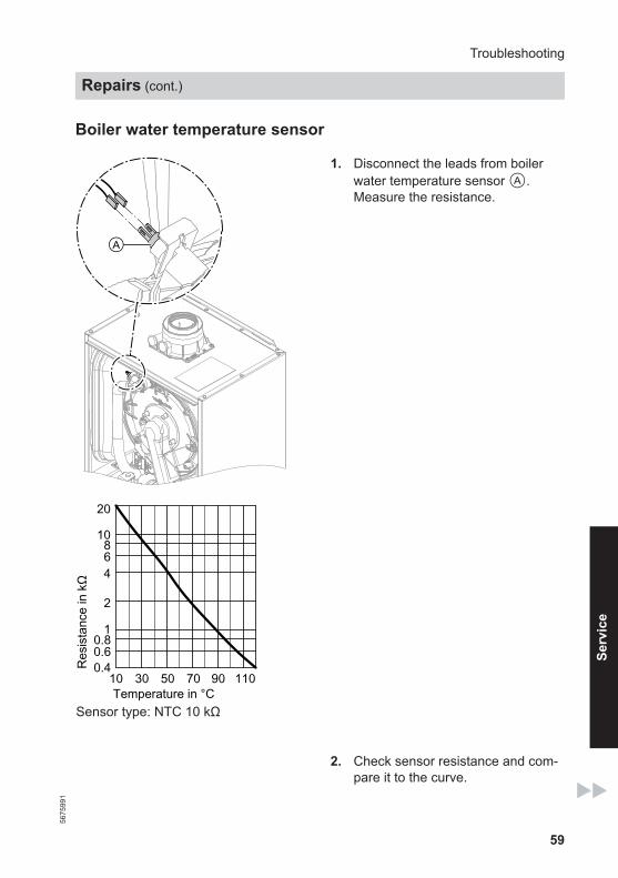
Boiler water temperature sensor
A
1. Disconnect the leads from boilerwater temperature sensor A.Measure the resistance.
10
1
10 30 50 70 90 110Temperature in °C
0.40.60.8
2
468
20
Res
ista
nce
in k
Ω
Sensor type: NTC 10 kΩ
2. Check sensor resistance and com-pare it to the curve.
Troubleshooting
Repairs (cont.)
5675
991
Serv
ice

60
3. In the case of severe deviation,drain the boiler on the heatingwater side and replace the sensor.
DangerThe boiler water tempera-ture sensor is directlyimmersed in the heatingwater (risk of scalding).Drain the boiler beforereplacing the sensor.
Checking the temperature limiter
A
If the burner control unit cannot bereset after a fault shutdown, althoughthe boiler water temperature is belowapprox. 95 °C, check the temperaturelimiter.
1. Disconnect the leads from tempera-ture limiter A.
2. Check the continuity of the temper-ature limiter with a multimeter.
3. Remove faulty temperature limiter.
4. Install a new temperature limiter.
5. Reset by pressing "Reset" on thecontrol unit (see page 55).
Troubleshooting
Repairs (cont.)
5675
991

61
Checking the outlet temperature sensor
A
1. Disconnect leads from outlet tem-perature sensor A.
2. Check sensor resistance and com-pare it to the curve.
10
1
10 30 50 70 90 110Temperature in °C
0.40.60.8
2
468
20
Res
ista
nce
in k
Ω
Sensor type: NTC 10 kΩ
3. In the event of severe deviationreplace the sensor.
NoteWater may escape when replacingthe outlet temperature sensor. Shutoff the cold water supply. Drain theDHW line and the plate heatexchanger (on the DHW side).
Troubleshooting
Repairs (cont.)
5675
991
Serv
ice

62
Checking the flue gas temperature sensor
A
1. Disconnect leads at flue gas tem-perature sensor A.
2. Check sensor resistance and com-pare it to the curve.
10
1
10 30 50 70 90 110Temperature in °C
0.40.60.8
2
468
20
Res
ista
nce
in k
Ω
Sensor type: NTC 10 kΩ
3. In the event of severe deviationreplace the sensor.
Troubleshooting
Repairs (cont.)
5675
991
63
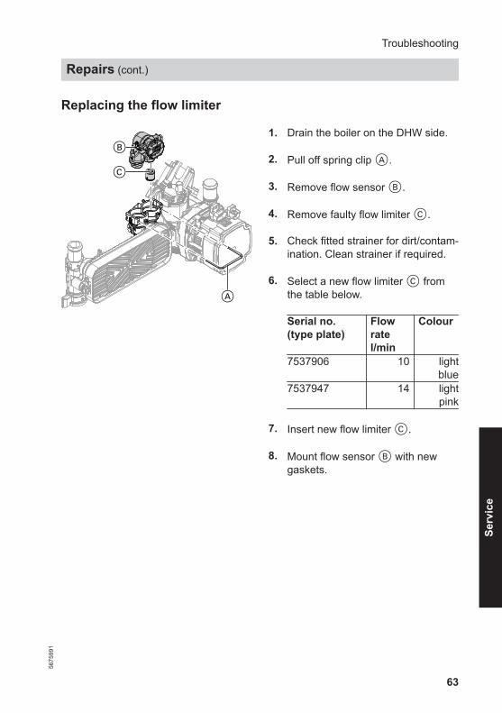
Replacing the flow limiter
B
C
A
1. Drain the boiler on the DHW side.
2. Pull off spring clip A.
3. Remove flow sensor B.
4. Remove faulty flow limiter C.
5. Check fitted strainer for dirt/contam-ination. Clean strainer if required.
6. Select a new flow limiter C fromthe table below.
Serial no.(type plate)
Flowratel/min
Colour
7537906 10 lightblue
7537947 14 lightpink
7. Insert new flow limiter C.
8. Mount flow sensor B with newgaskets.
Troubleshooting
Repairs (cont.)
5675
991
Serv
ice
64
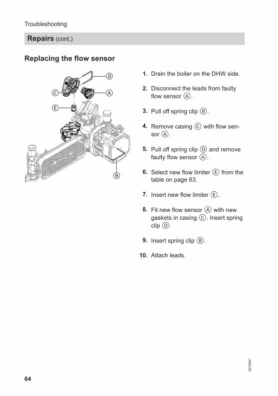
Replacing the flow sensor
C
E
B
A
D 01. Drain the boiler on the DHW side.
02. Disconnect the leads from faultyflow sensor A.
03. Pull off spring clip B.
04. Remove casing C with flow sen-sor A.
05. Pull off spring clip D and removefaulty flow sensor A.
06. Select new flow limiter E from thetable on page 63.
07. Insert new flow limiter E.
08. Fit new flow sensor A with newgaskets in casing C. Insert springclip D.
09. Insert spring clip B.
10. Attach leads.
Troubleshooting
Repairs (cont.)
5675
991
65
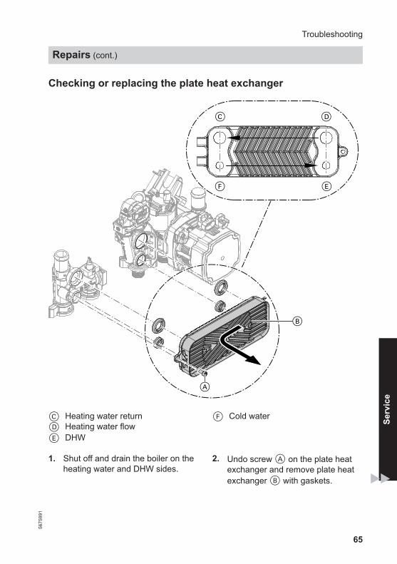
Checking or replacing the plate heat exchanger
C D
EF
A
B
C Heating water returnD Heating water flow E DHW
F Cold water
1. Shut off and drain the boiler on theheating water and DHW sides.
2. Undo screw A on the plate heatexchanger and remove plate heatexchanger B with gaskets.
Troubleshooting
Repairs (cont.)
5675
991
Serv
ice

66
NoteDuring and after removal, smallamounts of water may trickle fromthe plate heat exchanger.
3. Check the connections on the DHWside for scaling; clean or replacethe plate heat exchanger ifrequired.
4. Check the connections on the heat-ing water side for contamination;clean or replace the plate heatexchanger if required.
5. Install in reverse order using newgaskets.
NoteDuring installation, ensure the fixingholes are aligned and the gasketsare seated correctly. Fit the plateheat exchanger the right wayround.
Checking the fuse
F4
1. Switch off the power supply. 2. Open the control unit enclosure.
Troubleshooting
Repairs (cont.)
5675
991
67
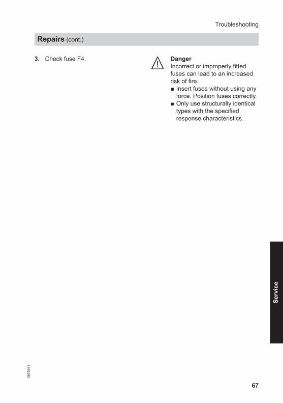
3. Check fuse F4. DangerIncorrect or improperly fittedfuses can lead to an increasedrisk of fire.■ Insert fuses without using any
force. Position fuses correctly.■ Only use structurally identical
types with the specifiedresponse characteristics.
Troubleshooting
Repairs (cont.)
5675
991
Serv
ice
68
Removing the gas restrictor
C
B
D
AF
E
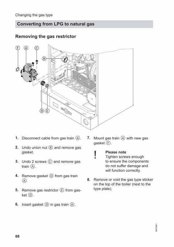
1. Disconnect cable from gas train A.
2. Undo union nut B and remove gasgasket.
3. Undo 2 screws C and remove gastrain A.
4. Remove gasket D from gas trainA.
5. Remove gas restrictor E from gas-ket D.
6. Insert gasket D in gas train A.
7. Mount gas train A with new gasgasket F.
! Please noteTighten screws enough to ensure the componentsdo not suffer damage andwill function correctly.
8. Remove or void the gas type stickeron the top of the boiler (next to thetype plate).
Changing the gas type
Converting from LPG to natural gas
5675
991
69
9. Start the boiler and check for leaks.
DangerEscaping gas leads to a riskof explosion.Check all gas equipment fortightness.
! Please noteThe use of leak detectionspray can result in faultyoperation.Leak detection spray mustnot come into contact withelectrical contacts or blockthe diaphragm opening onthe gas valve.
Converting the gas type at the control unit
1. Turn on the ON/OFF switch.
2. Press MODE and simultaneouslyand hold for 3 s."SERV" appears on the displayand "I" flashes.
3. Use / to select "5" and confirmwith OK."1" flashes on the display.
4. Use / to select "0" and confirmwith OK.The burner has been switched tooperation with natural gas.
5. Press MODE and simultaneouslyand hold for 3 s.Service mode is terminated. Serv-ice mode also terminates automati-cally after 30 min.
6. Turn the ON/OFF switch off and onagain.The selected gas type is now ena-bled.
Checking the CO2 content
See page 38.
Changing the gas type
Converting from LPG to natural gas (cont.)
5675
991
Serv
ice
70
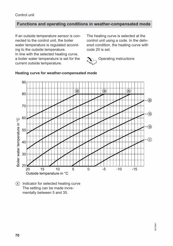
If an outside temperature sensor is con-nected to the control unit, the boilerwater temperature is regulated accord-ing to the outside temperature.In line with the selected heating curve,a boiler water temperature is set for thecurrent outside temperature.
The heating curve is selected at thecontrol unit using a code. In the deliv-ered condition, the heating curve withcode 20 is set.
Operating instructions
Heating curve for weather-compensated mode
20
30
40
50
60
70
80
90
Boile
r wat
er te
mpe
ratu
re in
°C
20 15 10 5 0 -5 -10 -15
5
wP
qT
qP
eT wTeP
Outside temperature in °C
X Indicator for selected heating curveThe setting can be made incre-mentally between 5 and 35.
Control unit
Functions and operating conditions in weather-compensated mode
5675
991
71
Frost protection function
The frost protection function requiresan outside temperature sensor to beconnected. Frost protection function isactive at outside temperatures of< 5 °C. The burner starts and the boilerwater temperature is held at 20 °C.
Control unit
Functions and operating conditions in… (cont.)
5675
991
Serv
ice

72
Overview
A
A Power supplyA1 Main PCB in control unit enclo-
sure on side panelA3 Programming unit
S1 ON/OFF switchX ... Electrical interface
Designs
Connection and wiring diagrams
5675
991

73
Programming unit
A
B
C
D
E
F
A Power supplyB Gas pressure switch (accesso-
ries)C Outside temperature sensor
(accessories)
D Room temperature controller(accessories)
E Time switch or wireless receiver(accessories)
Designs
Connection and wiring diagrams (cont.)
5675
991
Serv
ice
74
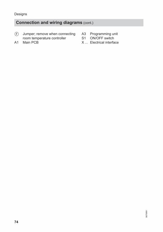
F Jumper; remove when connectingroom temperature controller
A1 Main PCB
A3 Programming unitS1 ON/OFF switchX ... Electrical interface
Designs
Connection and wiring diagrams (cont.)
5675
991

75
Control unit
A
B
C
D
A Programming unit connection
Designs
Connection and wiring diagrams (cont.)
5675
991
Serv
ice
76
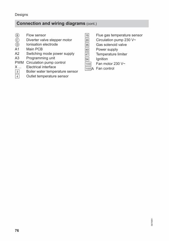
B Flow sensorC Diverter valve stepper motorD Ionisation electrodeA1 Main PCBA2 Switching mode power supplyA3 Programming unitPWM Circulation pump controlX ... Electrical interface§ Boiler water temperature sensor$ Outlet temperature sensor
aG Flue gas temperature sensorsÖ Circulation pump 230 V~dG Gas solenoid valvefÖ Power supplyfJ Temperature limitergF Ignitiona-Ö Fan motor 230 V~a-ÖA Fan control
Designs
Connection and wiring diagrams (cont.)
5675
991
77
The following details are requiredwhen ordering parts:■ Serial no. (see type plate A)■ Assembly (from this parts list)■ Position number of the individual part
within the assembly (from this partslist)
Parts lists
Overview of assemblies56
7599
1
Serv
ice

78
A
B C
D E
F
A Type plateB Casing assemblyC Heat cell assembly
D Hydraulic assemblyE Control unit assemblyF Miscellaneous assembly
Parts lists
Overview of assemblies (cont.)
5675
991

79
Parts lists
Overview of assemblies (cont.)
5675
991
Serv
ice

80
00020003
0003
0001
0002
0004
Pos. Part0001 Front panel0002 Profiled seal0003 Viessmann logo0004 Wall mounting bracket
Parts lists
Casing assembly
5675
991

81
Parts lists
Casing assembly (cont.)
5675
991
Serv
ice

82
0008
0007
0018
0004001300140015
0006
00010003
0011
0017
0016
0009
0013
0012
0010
0011
0015
0004
00030014
0014
0014
0002
00010005
Parts lists
Heat cell assembly
5675
991
83
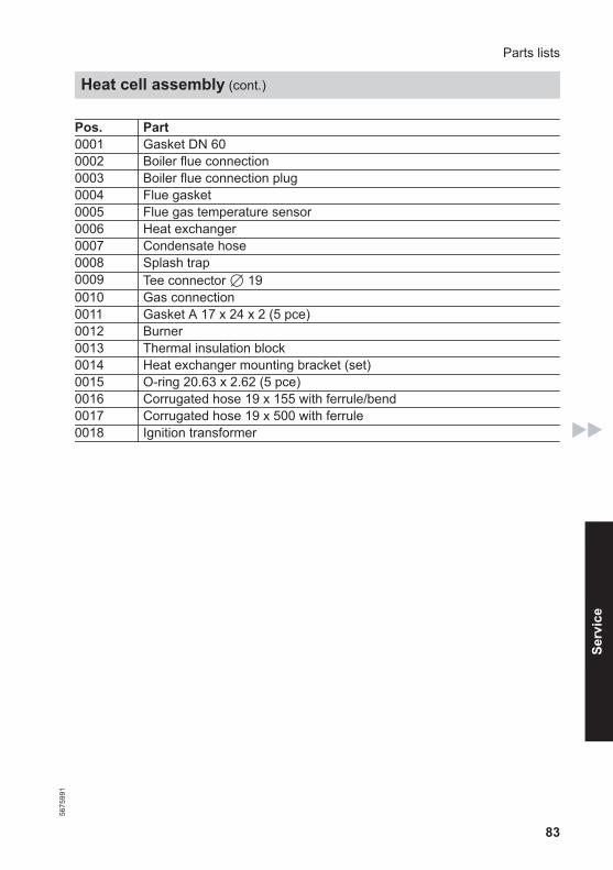
Pos. Part0001 Gasket DN 600002 Boiler flue connection0003 Boiler flue connection plug0004 Flue gasket0005 Flue gas temperature sensor0006 Heat exchanger0007 Condensate hose0008 Splash trap0009 Tee connector 7 190010 Gas connection0011 Gasket A 17 x 24 x 2 (5 pce)0012 Burner0013 Thermal insulation block0014 Heat exchanger mounting bracket (set)0015 O-ring 20.63 x 2.62 (5 pce)0016 Corrugated hose 19 x 155 with ferrule/bend0017 Corrugated hose 19 x 500 with ferrule0018 Ignition transformer
Parts lists
Heat cell assembly (cont.)
5675
991
Serv
ice
84
0004
0003 0002 00010004
0006
0001000400060008
00080012
0012
0012
0010
0013 0011
0011
0009
0008
0007 0006 0005
0012
Parts lists
Burner assembly
5675
991
85
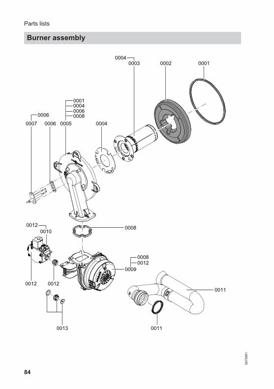
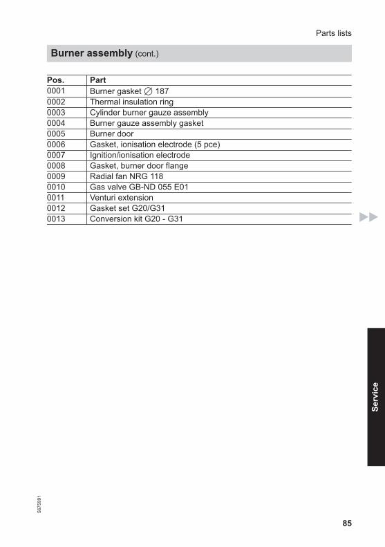
Pos. Part0001 Burner gasket 7 1870002 Thermal insulation ring0003 Cylinder burner gauze assembly0004 Burner gauze assembly gasket0005 Burner door0006 Gasket, ionisation electrode (5 pce)0007 Ignition/ionisation electrode0008 Gasket, burner door flange0009 Radial fan NRG 1180010 Gas valve GB-ND 055 E010011 Venturi extension0012 Gasket set G20/G310013 Conversion kit G20 - G31
Parts lists
Burner assembly (cont.)
5675
991
Serv
ice

86
0002
0001
0003
0004
0011
0018
0017
0014
0008
0018
0006
0007
0005
0010
0009
0015
0012
00100009
0007
00070018
00070018
0008
0003
0009
0016000700090010
0013
000300090012
00070010
0019
Parts lists
Hydraulic assembly
5675
991
87
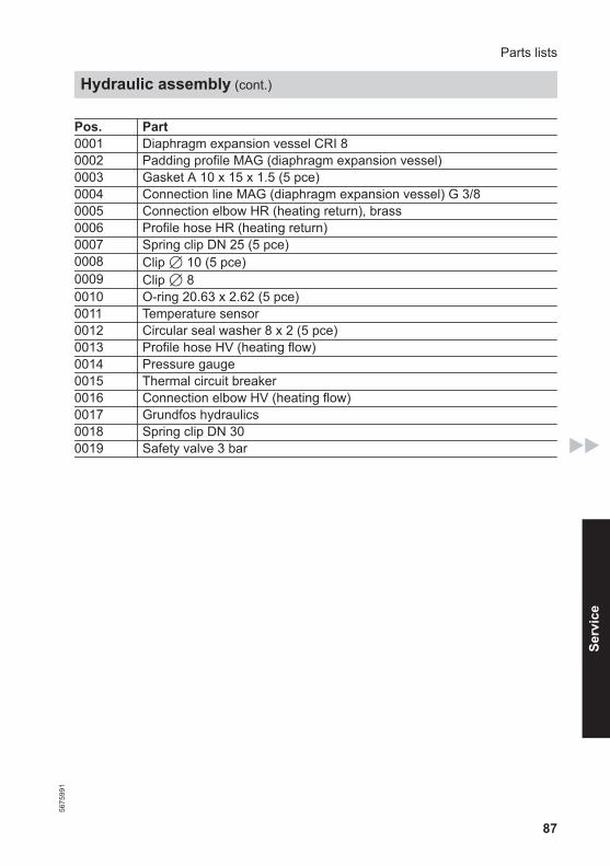
Pos. Part0001 Diaphragm expansion vessel CRI 80002 Padding profile MAG (diaphragm expansion vessel)0003 Gasket A 10 x 15 x 1.5 (5 pce)0004 Connection line MAG (diaphragm expansion vessel) G 3/80005 Connection elbow HR (heating return), brass0006 Profile hose HR (heating return)0007 Spring clip DN 25 (5 pce)0008 Clip 7 10 (5 pce)0009 Clip 7 80010 O-ring 20.63 x 2.62 (5 pce)0011 Temperature sensor0012 Circular seal washer 8 x 2 (5 pce)0013 Profile hose HV (heating flow)0014 Pressure gauge0015 Thermal circuit breaker0016 Connection elbow HV (heating flow)0017 Grundfos hydraulics0018 Spring clip DN 300019 Safety valve 3 bar
Parts lists
Hydraulic assembly (cont.)
5675
991
Serv
ice

88
0030
0003
0019
0002 0006
0001
0010
00100005
0008
0028
0018
0011
00040005
0015
00150020 0012
0022
00220022
0022
00040010
0023
0025
0009
0028
00100010
000400050009001100120015001800200028
0011
0028
0006
0019
0010
00100010
00020003000400050006
Parts lists
Grundfos hydraulic assembly
5675
991

89
Pos. Part0001 Flow casing EU10002 Temperature sensor0003 Expansion vessel0004 O-ring 19.8 x 3.6 (5 pce)0005 O-ring 16 x 3 (5 pce)0006 Clip 7 8, narrow (5 pce)0008 Plate heat exchanger0009 Circulation pump motor0010 Return casing0011 Flow limiter0012 Stepper motor0015 Air vent valve0018 Flow sensor0019 Clip 7 80020 Clip 7 160022 Connection elbow0023 Air box floor0025 Dummy adaptor, time switch0028 Gasket set, plate heat exchanger0030 Tee connector 7 19
Parts lists
Grundfos hydraulic assembly (cont.)
5675
991
Serv
ice

90
0001
0010
0002
0009000800070006
000500040003
Parts lists
Control unit assembly
5675
991
91
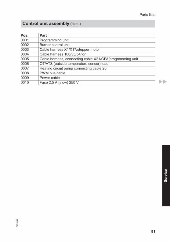
Pos. Part0001 Programming unit0002 Burner control unit0003 Cable harness X1/X17/stepper motor0004 Cable harness 100/35/54/ion0005 Cable harness, connecting cable X21/GFA/programming unit0006 OT/ATS (outside temperature sensor) lead0007 Heating circuit pump connecting cable 200008 PWM bus cable0009 Power cable0010 Fuse 2.5 A (slow) 250 V
Parts lists
Control unit assembly (cont.)
5675
991
Serv
ice

92
0004
0005
0003
0002
0001
Pos. Part0001 Touch-up spray paint, white, 150 ml can0002 Touch-up paint stick, white0003 Special grease0004 Operating instructions0005 Installation and service instructions
Parts lists
Miscellaneous assembly
5675
991
93
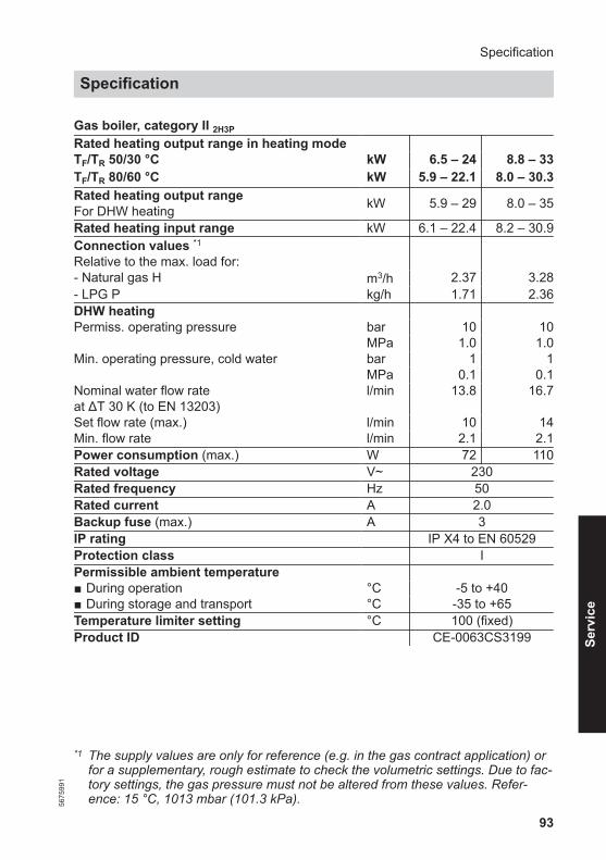
Gas boiler, category II 2H3P
Rated heating output range in heating mode TF/TR 50/30 °C kW 6.5 – 24 8.8 – 33TF/TR 80/60 °C kW 5.9 – 22.1 8.0 – 30.3Rated heating output rangeFor DHW heating kW 5.9 – 29 8.0 – 35
Rated heating input range kW 6.1 – 22.4 8.2 – 30.9Connection values *1Relative to the max. load for:
- Natural gas H m3/h 2.37 3.28- LPG P kg/h 1.71 2.36DHW heating Permiss. operating pressure bar 10 10 MPa 1.0 1.0Min. operating pressure, cold water bar 1 1 MPa 0.1 0.1Nominal water flow rateat ΔT 30 K (to EN 13203)
l/min 13.8 16.7
Set flow rate (max.) l/min 10 14Min. flow rate l/min 2.1 2.1Power consumption (max.) W 72 110Rated voltage V~ 230Rated frequency Hz 50Rated current A 2.0Backup fuse (max.) A 3IP rating IP X4 to EN 60529Protection class IPermissible ambient temperature ■ During operation °C -5 to +40■ During storage and transport °C -35 to +65Temperature limiter setting °C 100 (fixed)Product ID CE-0063CS3199
*1 The supply values are only for reference (e.g. in the gas contract application) orfor a supplementary, rough estimate to check the volumetric settings. Due to fac-tory settings, the gas pressure must not be altered from these values. Refer-ence: 15 °C, 1013 mbar (101.3 kPa).
Specification
Specification56
7599
1
Serv
ice

94
Viessmann products can be recycled.Components and substances from thesystem are not part of ordinary house-hold waste.For decommissioning the system, iso-late the system from the power supplyand allow components to cool downwhere appropriate.
All components must be disposed ofcorrectly.
Disposal
Final decommissioning and disposal
5675
991

95
Vitodens 050-W, type BPJD
We, Viessmann Werke GmbH & Co. KG, D-35107 Allendorf, declare as soleresponsible body that the named product complies with the provisions of the follow-ing directives and regulations:
92/42/EEC Efficiency Directive2016/426/EU Gas Appliances Regulation2014/30/EU EMC Directive2014/35/EU Low Voltage Directive2009/125/EC Ecodesign Framework Directive2010/30/EU Energy Consumption Labelling Framework Directive811/2013 EU Regulation "Energy Efficiency Label" (only applicable up to 70
kW)813/2013 EU Regulation "Energy Efficiency Requirements"
Applied standards:EN 15502-1: 2012 + A1: 2015EN 15502-2-1: 2012 + A1: 2016EN 55014-1: 2006 + A1: 2009 + A2: 2011EN 55014-2: 2015EN 60335-1: 2012 + AC: 2014EN 60335-2-102: 2006 + A1: 2010EN 61000-3-2: 2014EN 61000-3-3: 2013
In accordance with the listed directives, this product is designated with .
Allendorf, 1 March 2018 Viessmann Werke GmbH & Co. KG
Authorised signatory Reiner JansenHead of Strategic Quality Management
Manufacturer's declaration
This product meets the requirements of the Efficiency Directive (92/42/EEC) forcondensing boilers.
Certificates
Declaration of conformity56
7599
1
Serv
ice
96
BBoiler water temperature sensor .......59Burner gasket.....................................42Burner gauze assembly..................... 42Burner installation.............................. 47Burner removal.................................. 42
CCombustion chamber cleaning.......... 45Commissioning.................................. 27Condensate........................................20Condensate drain.........................20, 46Connection diagram...........................72– Control unit..................................... 75– Programming unit........................... 73Connections.......................................18Connections on the water side...........18
EElectrical connections........................ 23
FFault code.......................................... 52Fault display.......................................52Filling function....................................27Flow limiter.........................................63Flow sensor........................................64Flue gas temperature sensor............. 62Flue pipe............................................ 21Frost limit........................................... 71Frost protection.................................. 71Function sequence.............................51Fuse...................................................66
GGas connection..................................19Gas supply pressure.......................... 32Gas train ........................................... 31Gas type conversion.......................... 68– LPG................................................ 30– Natural gas..................................... 68
HHeat exchanger cleaning................... 45Heating curve.....................................70
IIgnition............................................... 44Ignition electrode................................44Ionisation electrode............................44
MMax. heating output........................... 32
OOutlet temperature sensor................. 61Output adjustment– Shared connection..........................34Output matching to flue system......... 33Output reduction................................ 32Outside temperature sensor........ 24, 58
PPlate heat exchanger.........................65Power supply..................................... 24Programming unit, opening................22
RReset..................................................55
SSafety chain ...................................... 60Safety valve....................................... 20Shared flue system connection..........34Software version................................ 55Static pressure................................... 31Supply pressure.................................30System filling................................27, 29System pressure................................ 29
TTemperature limiter............................ 60Trap..............................................21, 46Troubleshooting................................. 57
Keyword index
Keyword index
5675
991

97
VVentilation air pipe..............................21
WWall mounting.................................... 15Weather-compensated mode.............70
Keyword index
Keyword index (cont.)
5675
991

98
5675
991

99
5675
991

100
Viessmann LimitedHortonwood 30, TelfordShropshire, TF1 7YP, GBTelephone: +44 1952 675000Fax: +44 1952 675040E-mail: [email protected]
Viessmann Werke GmbH & Co. KGD-35107 AllendorfTelephone: +49 6452 70-0Fax: +49 6452 70-2780www.viessmann.com
5675
991
Sub
ject
to te
chni
cal m
odifi
catio
ns.