Embed Size (px)
Citation preview
Operating and Service Manual
20T4G18 Model 1008254-501 Part Number Serial Number

Model 20T4G18
2

EC Declaration of Conformity
We; Amplifier Research 160 School House Road Souderton, PA 18964 declare that our product;
the Model 200T4G18 amplifier to which this declaration relates is in compliance with the requirements of the EEC EMC Directive (89/336/EEC) and Low Voltage Directive (73/23/EEC) in accordance with the relative standards listed below:
EMC: EN 50082-1: 1992 Electromagnetic compatibility – Generic immunity standard EN 50081-1: 1992 Electromagnetic emissions requirements for Industrial, Scientific, and
Medical (ISM) Equipment Safety: EN 60950 (1995)
The CE marking is affixed on the device according to the EC Directives.
Donald R. Shepherd President

Model 20T4G18
4
INSTRUCTIONS FOR SAFE OPERATION
BEFORE APPLYING POWER SAFETY SYMBOLS
This symbol is marked on the equipment when it is necessary for the user to refer to the manual for important safety information.
Dangerous voltages are present. Use extreme care.
CAUTION: The caution symbol denotes a potential hazard. Attention must be given to the statement to prevent damage, destruction, or harm.
Indicates protective earth terminal.
Review this manual and become familiar with all safety markings and instructions.
Verify that the equipment line voltage selection is compatible with the main power source.
Protection provided by the equipment may be impaired if used in a manner not specified by Amplifier Research.
INTENDED PURPOSES This equipment is intended for general laboratory use in a wide variety of industrial and scientific applications. It is designed to be used in the process of generating, controlling, and measuring high levels of electromagnetic Radio Frequency (RF) energy. Therefore, the output of the amplifier must be connected to an appropriate load such as an antenna or field-generating device. It is the responsibility of the user to assure that the device is operated in a location which will control the radiated energy such that it will not cause injury and will not violate regulatory levels of electromagnetic interference.
RANGE OF ENVIRONMENTAL CONDITIONS This equipment is designed to be safe under the following environmental conditions:
HAZARDOUS RF VOLTAGES • Indoor use • Altitude up to 2000M The RF voltages on the center pin of the RF output connector
can be hazardous. The RF output connector should be connected to a load before AC power is applied to the amplifier. Do not come into contact with the center pin of the RF output connector or accessories connected to it. Place the equipment in a non-operating condition before disconnecting or connecting the load to the RF output connector.
• Temperature of 5°C to 40°C • Maximum relative humidity 80% for temperatures up to
31°C. Decreasing linearly to 50% at 40°C. • Main supply voltage fluctuations not to exceed ± 10% of
the nominal voltage or minimum and maximum autoranging values.
• Pollution degree 2: Normally non-conductive with occasional condensation. While the equipment will not cause hazardous condition over this environmental range, its performance may vary.
SAFETY GROUND This equipment is provided with a protective earth terminal. The main power source to the equipment must supply an uninterrupted safety ground of sufficient size to the input wiring terminals, power cord, or supplied power cord set. The equipment MUST NOT BE USED if this protection is impaired.
COOLING AIR Care should be exercised not to block the cooling air inlets or outlets. Cooling air blockage can result in damage to the RF amplifier or intermittent shut-downs.
PHYSICAL DAMAGE The RF amplifier should not be operated if there is physical damage, missing hardware, or missing panels.
MAINTENANCE CAUTION Adjustment, maintenance, or repair of the equipment must be performed only by qualified personnel. Hazardous energy may be present while protective covers are removed from the equipment even if disconnected from the power source. Contact may result in personal injury. Replacement fuses are required to be of specific type and current rating.

Model 20T4G18
2
ADDITIONAL WARNINGS & NOTES
WARNING: This equipment operates at potentially lethal voltages. Only trained,
qualified personnel should operate, maintain, or service it.
Hazardous energy may be present while protective covers are removed from the equipment even if disconnected from the power source. Contact may result in personal injury.
CAUTION:
Adjustment, maintenance, or repair of the equipment must be performed only by qualified personnel.
CAUTION:
Replacement fuses are required to be of specific type and current rating.
CAUTION:
The information in this document was obtained from reliable sources and was believed to be accurate at the time of publication. Since subsequent modifications to the machine may have been made, use this information only as a guide. Carefully compare the unit's actual configuration and operation to the descriptions in this manual before you undertake to operate, service, or modify this machine. Any variance or modification should be noted, dated, and initialed in the discrepant part of all manuals on hand for future reference. If you have technical or editorial comments you wish to make to the manufacturer, please write them on photocopies of the relevant sheets.
NOTE: The contents of this document are the property of the manufacturer and this document is delivered on the express condition that it not be disclosed, reproduced in whole or in part, or used for manufacture for anyone other than the manufacturer without its written consent, and that no right is granted to disclose or so use any information in this document.

Model 20T4G18
4
TABLE OF CONTENTS
TABLE OF CONTENTS .................................................................................................. i
1. DESCRIPTION AND SPECIFICATIONS..............................................................1 1.1 TWTA Description.....................................................................................................1 1.2 Suggested Applications..............................................................................................1 1.3 Specifications .............................................................................................................1 1.4 Accessories.................................................................................................................1 1.5 Test Data Sheet ..........................................................................................................2
2. THEORY OF OPERATION.....................................................................................5 2.1 Design of the amplifier...............................................................................................5 2.2 Description of the RF Circuit .....................................................................................5 2.3 Description of the Power Supply ...............................................................................6
3. OPERATION..............................................................................................................7 3.1 Warnings and Cautions ..............................................................................................7 3.2 Installation..................................................................................................................8 3.2.1 Unpacking ...............................................................................................................8 3.2.2 Mounting.................................................................................................................8 3.2.3 Cooling Requirements.............................................................................................9 3.2.4 AC Line Power Connections.................................................................................10 3.2.5 RF Output Connections.........................................................................................10 3.2.6 External Interlock Connector ................................................................................10 3.3 Front Panel Features.................................................................................................11 3.4 Front Panel Display and Soft Keys ..........................................................................12 3.5 Rear Panel Features..................................................................................................16 3.6 Initial Turn On and Warm-up Procedure .................................................................16 3.7 Emergency Bypass Operation ..................................................................................17 3.8 Remote IEEE-488 Operation ...................................................................................18 3.9 TWTA General Considerations................................................................................23
4. MAINTENANCE .....................................................................................................25 4.1 Safety Warning ........................................................................................................25 4.2 Unauthorized Repairs...............................................................................................25 4.3 Preventive Maintenance ...........................................................................................25 4.4 Troubleshooting .......................................................................................................26 4.5 Non-Repairable Modules .........................................................................................27
5. TECHNICAL DOCUMENTATION......................................................................29 5.1 Top Level Build Tree ...............................................................................................30 5.2 Schematics................................................................................................................31 5.3 Wiring Diagrams......................................................................................................33 5.4 Parts Lists .................................................................................................................35 5.4.1 Parts List, HPA Logic and Control Module, A16485-000....................................36 5.4.2 Parts List, Power Supply (Short) For TWT 5172, A23720-099 ...........................38 5.4.3 Parts List, Emergency Bypass Board, A24830-001..............................................39 5.4.4 Parts List, Emergency Bypass Board, A24830-002..............................................40 5.4.5 Parts List, HPA Interface Board (Plastic), A25444-000 .......................................41
i
Model 20T4G18
5.4.6 Parts List, HPA 20W 4.2-18GHZ (AR), A28825-300..........................................44 5.4.7 Parts List, Microwave Power Assembly, AR, A28826-000..................................45 5.5 Recommended Spare Parts.......................................................................................46 5.6 Sample Program for IEEE-488 Communication......................................................47
ILLUSTRATIONS Figure 3-1 - Rear View of HPA ..........................................................................................9 Figure 3-2 - TWTA Front Panel Features .........................................................................11 Figure 3-3 - Front Panel Display Screens..........................................................................12 Figure 3-4 - TWTA Rear Panel Features...........................................................................15 TABLES Table 1 - Front Panel Features.............................................................................................9 Table 2 - Rear Panel Features............................................................................................15 Table 3 - Catalog of IEEE-488 Commands.......................................................................17 Table 4 - Catalog of Status Codes .....................................................................................18 Table 5 - Catalog of Fault Codes.......................................................................................19 Table 6 - Catalog of System State Codes ..........................................................................19 Table 7 - Catalog of *STA?; Response Codes ..................................................................20 Table 8 - Catalog of *STB?; Response Codes ..................................................................20
ii
1. DESCRIPTION AND SPECIFICATIONS
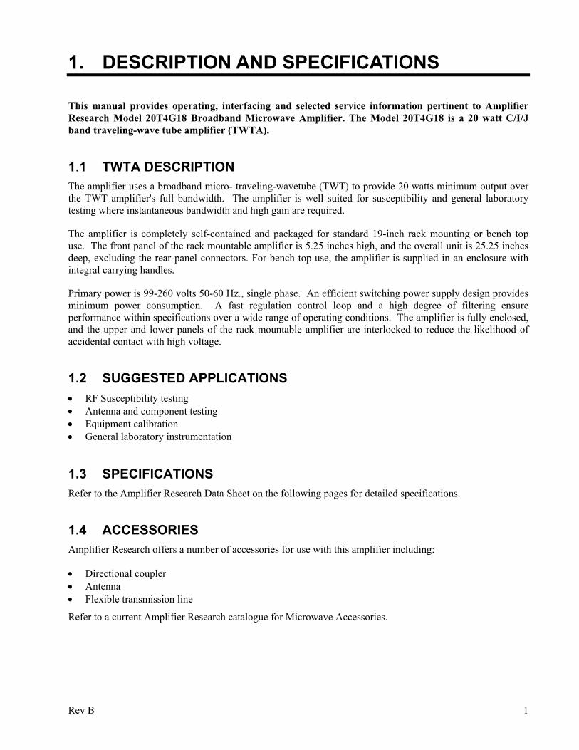
This manual provides operating, interfacing and selected service information pertinent to Amplifier Research Model 20T4G18 Broadband Microwave Amplifier. The Model 20T4G18 is a 20 watt C/I/J band traveling-wave tube amplifier (TWTA).
1.1 TWTA DESCRIPTION The amplifier uses a broadband micro- traveling-wavetube (TWT) to provide 20 watts minimum output over the TWT amplifier's full bandwidth. The amplifier is well suited for susceptibility and general laboratory testing where instantaneous bandwidth and high gain are required.
The amplifier is completely self-contained and packaged for standard 19-inch rack mounting or bench top use. The front panel of the rack mountable amplifier is 5.25 inches high, and the overall unit is 25.25 inches deep, excluding the rear-panel connectors. For bench top use, the amplifier is supplied in an enclosure with integral carrying handles.
Primary power is 99-260 volts 50-60 Hz., single phase. An efficient switching power supply design provides minimum power consumption. A fast regulation control loop and a high degree of filtering ensure performance within specifications over a wide range of operating conditions. The amplifier is fully enclosed, and the upper and lower panels of the rack mountable amplifier are interlocked to reduce the likelihood of accidental contact with high voltage.
1.2 SUGGESTED APPLICATIONS • RF Susceptibility testing • Antenna and component testing • Equipment calibration • General laboratory instrumentation
1.3 SPECIFICATIONS Refer to the Amplifier Research Data Sheet on the following pages for detailed specifications.
1.4 ACCESSORIES Amplifier Research offers a number of accessories for use with this amplifier including:
• Directional coupler • Antenna • Flexible transmission line
Refer to a current Amplifier Research catalogue for Microwave Accessories.
Rev B 1

Model 20T4G18
1.5 TEST DATA SHEET A Test Data Sheet for a specific unit is prepared at the time of manufacture and is included with the unit's copy of this manual.
2 Rev B
160 School House Road, Souderton, PA 18964-9990 USAPhone 215-723-8181•FAX 215-723-5688
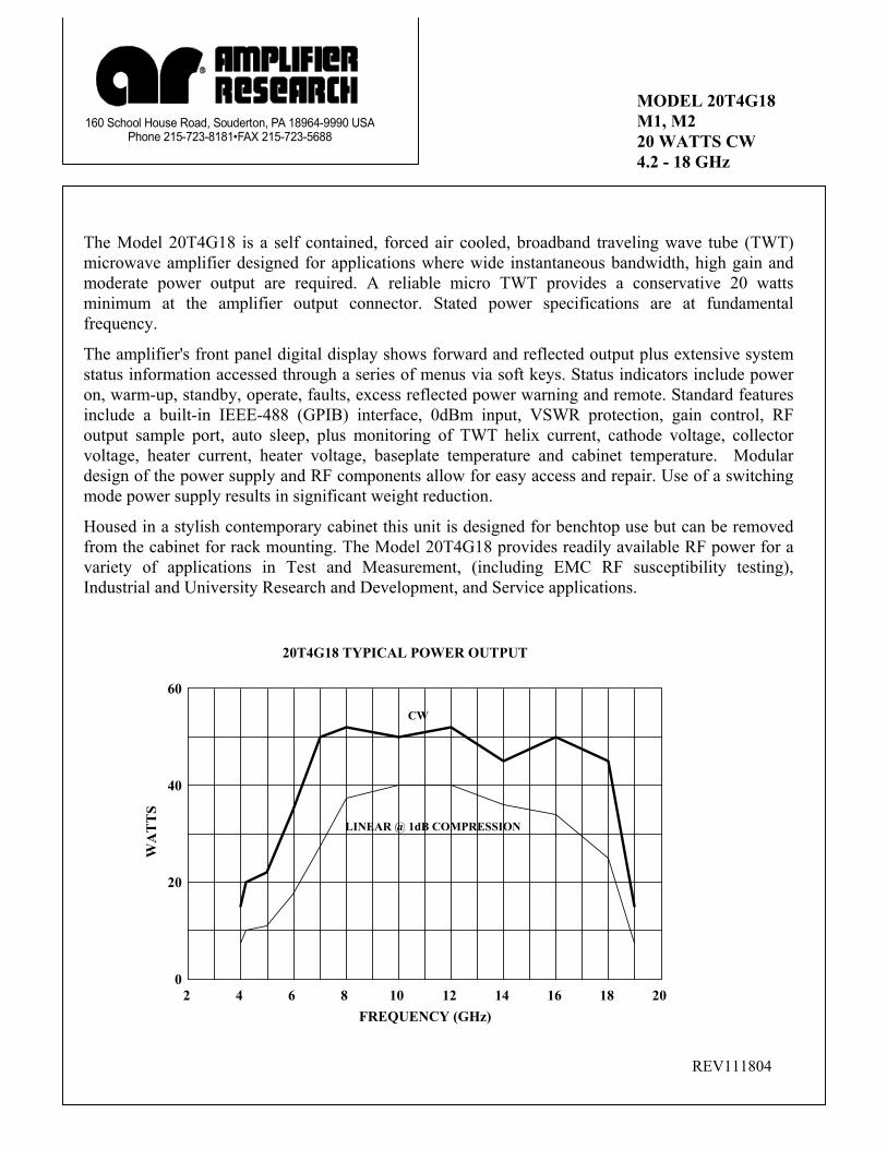
MODEL 20T4G18 M1, M2 20 WATTS CW 4.2 - 18 GHz
The Model 20T4G18 is a self contained, forced air cooled, broadband traveling wave tube (TWT) microwave amplifier designed for applications where wide instantaneous bandwidth, high gain and moderate power output are required. A reliable micro TWT provides a conservative 20 watts minimum at the amplifier output connector. Stated power specifications are at fundamental frequency.
The amplifier's front panel digital display shows forward and reflected output plus extensive system status information accessed through a series of menus via soft keys. Status indicators include power on, warm-up, standby, operate, faults, excess reflected power warning and remote. Standard features include a built-in IEEE-488 (GPIB) interface, 0dBm input, VSWR protection, gain control, RF output sample port, auto sleep, plus monitoring of TWT helix current, cathode voltage, collector voltage, heater current, heater voltage, baseplate temperature and cabinet temperature. Modular design of the power supply and RF components allow for easy access and repair. Use of a switching mode power supply results in significant weight reduction.
Housed in a stylish contemporary cabinet this unit is designed for benchtop use but can be removed from the cabinet for rack mounting. The Model 20T4G18 provides readily available RF power for a variety of applications in Test and Measurement, (including EMC RF susceptibility testing), Industrial and University Research and Development, and Service applications.
0
20
40
60
WA
TT
S
2 4 6 8 10 12 14 16 18 20 FREQUENCY (GHz)
20T4G18 TYPICAL POWER OUTPUT
CW
LINEAR @ 1dB COMPRESSION
REV111804
SPECIFICATIONS Model 20T4G18
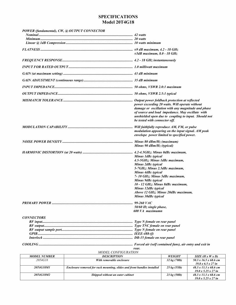
POWER (fundamental), CW, @ OUTPUT CONNECTOR Nominal ........................................................................................................... 42 watts Minimum ......................................................................................................... 20 watts Linear @ 1dB Compression ............................................................................ 10 watts minimum FLATNESS ......................................................................................................... ±9 dB maximum, 4.2 - 18 GHz ±5dB maximum, 8.0 - 18 GHz FREQUENCY RESPONSE................................................................................ 4.2 - 18 GHz instantaneously INPUT FOR RATED OUTPUT ......................................................................... 1.0 milliwatt maximum GAIN (at maximum setting) ............................................................................... 43 dB minimum GAIN ADJUSTMENT (continuous range)........................................................ 35 dB minimum INPUT IMPEDANCE......................................................................................... 50 ohms, VSWR 2.0:1 maximum OUTPUT IMPEDANCE..................................................................................... 50 ohms, VSWR 2.5:1 typical MISMATCH TOLERANCE ............................................................................... Output power foldback protection at reflected power exceeding 20 watts. Will operate without damage or oscillation with any magnitude and phase of source and load impedance. May oscillate with unshielded open due to coupling to input. Should not be tested with connector off. MODULATION CAPABILITY .......................................................................... Will faithfully reproduce AM, FM, or pulse modulation appearing on the input signal. AM peak envelope power limited to specified power. NOISE POWER DENSITY ................................................................................ Minus 80 dBm/Hz (maximum) Minus 90 dBm/Hz (typical) HARMONIC DISTORTION (at 20 watts) ......................................................... 4.2-4.5GHz; Minus 0dBc maximum, Minus 1dBc typical 4.5-5GHz; Minus 1dBc maximum, Minus 2dBc typical 5-7GHz; Minus 2.5dBc maximum, Minus 4dBc typical 7- 10 GHz; Minus 5dBc maximum, Minus 9dBc typical 10 - 12 GHz; Minus 8dBc maximum, Minus 12dBc typical Above 12 GHz; Minus 20dBc maximum, Minus 30dBc typical PRIMARY POWER ............................................................................................ 99-260 VAC 50/60 Hz single phase, 600 VA maximumn CONNECTORS RF input....................................................................................................... Type N female on rear panel RF output..................................................................................................... Type TNC female on rear panel RF output sample port................................................................................. Type N female on rear panel GPIB............................................................................................................ IEEE-488-(f) Interlock ...................................................................................................... DB-15 female on rear panel COOLING ........................................................................................................... Forced air (self contained fans), air entry and exit in
rear. MODEL CONFIGURATION
MODEL NUMBER DESCRIPTION WEIGHT SIZE (H x W x D) 20T4G18 With removable enclosure 32 kg (70lb) 50.3 x 16.5 x 68.6 cm
19.8 x 6.5 x 27 in 20T4G18M1 Enclosure removed for rack mounting, slides and front handles installed 25 kg (55lb) 48.3 x 13.3 x 68.6 cm
19.0 x 5.25 x 27 in 20T4G18M2 Shipped without an outer cabinet 23 kg (50lb) 48.3 x 13.3 x 68.6 cm
19.0 x 5.25 x 27 in
2. THEORY OF OPERATION
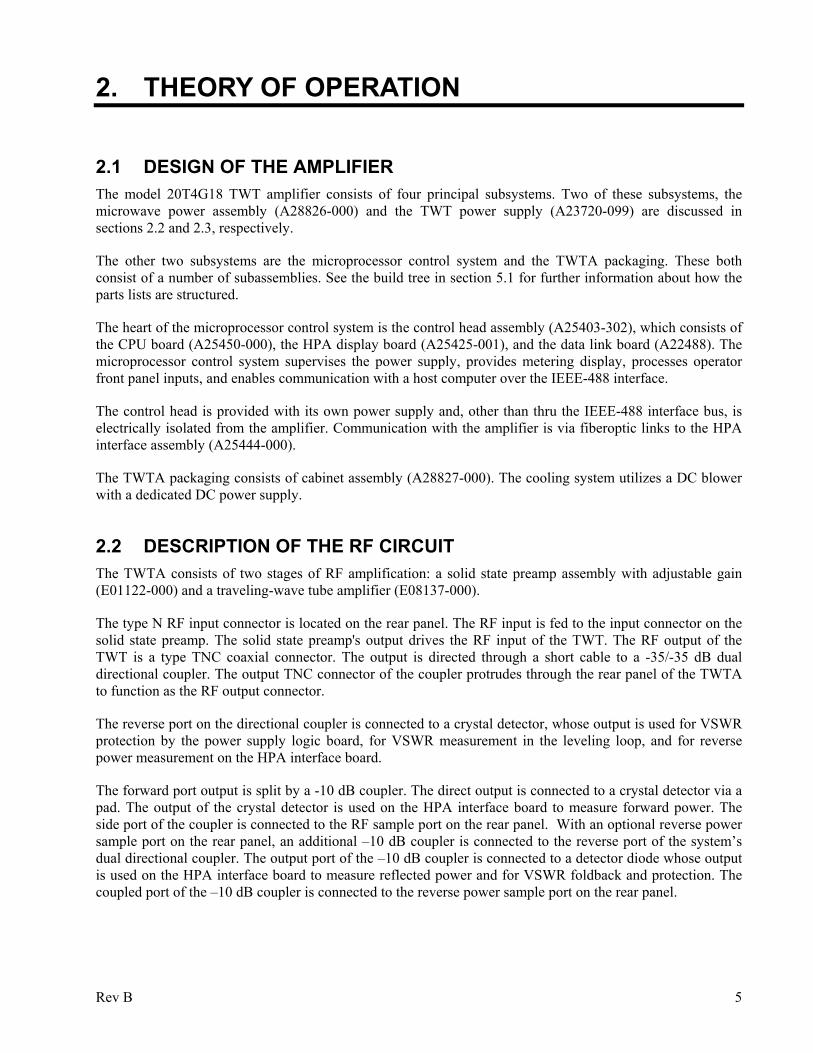
2.1 DESIGN OF THE AMPLIFIER The model 20T4G18 TWT amplifier consists of four principal subsystems. Two of these subsystems, the microwave power assembly (A28826-000) and the TWT power supply (A23720-099) are discussed in sections 2.2 and 2.3, respectively.
The other two subsystems are the microprocessor control system and the TWTA packaging. These both consist of a number of subassemblies. See the build tree in section 5.1 for further information about how the parts lists are structured.
The heart of the microprocessor control system is the control head assembly (A25403-302), which consists of the CPU board (A25450-000), the HPA display board (A25425-001), and the data link board (A22488). The microprocessor control system supervises the power supply, provides metering display, processes operator front panel inputs, and enables communication with a host computer over the IEEE-488 interface.
The control head is provided with its own power supply and, other than thru the IEEE-488 interface bus, is electrically isolated from the amplifier. Communication with the amplifier is via fiberoptic links to the HPA interface assembly (A25444-000).
The TWTA packaging consists of cabinet assembly (A28827-000). The cooling system utilizes a DC blower with a dedicated DC power supply.
2.2 DESCRIPTION OF THE RF CIRCUIT The TWTA consists of two stages of RF amplification: a solid state preamp assembly with adjustable gain (E01122-000) and a traveling-wave tube amplifier (E08137-000).
The type N RF input connector is located on the rear panel. The RF input is fed to the input connector on the solid state preamp. The solid state preamp's output drives the RF input of the TWT. The RF output of the TWT is a type TNC coaxial connector. The output is directed through a short cable to a -35/-35 dB dual directional coupler. The output TNC connector of the coupler protrudes through the rear panel of the TWTA to function as the RF output connector.
The reverse port on the directional coupler is connected to a crystal detector, whose output is used for VSWR protection by the power supply logic board, for VSWR measurement in the leveling loop, and for reverse power measurement on the HPA interface board.
The forward port output is split by a -10 dB coupler. The direct output is connected to a crystal detector via a pad. The output of the crystal detector is used on the HPA interface board to measure forward power. The side port of the coupler is connected to the RF sample port on the rear panel. With an optional reverse power sample port on the rear panel, an additional –10 dB coupler is connected to the reverse port of the system’s dual directional coupler. The output port of the –10 dB coupler is connected to a detector diode whose output is used on the HPA interface board to measure reflected power and for VSWR foldback and protection. The coupled port of the –10 dB coupler is connected to the reverse power sample port on the rear panel.
Rev B 5
Model 20T4G18 Amplifier gain is determined by the solid state preamp (SSA), which has a voltage-controlled attenuator. The control head determines the output of a digital-to-analog converter (DAC) on the HPA interface board. The output of the DAC controls the SSA attenuator. The emergency bypass board (A24830) mounted behind the front panel is provided with a circuit that increases the attenuation so that forward power is limited to a level on the order of 50 watts. Forward power is also limited so that reverse power does not exceed approximately 20 watts. In emergency bypass operation (see section 3.7) the gain control signal is provided locally by means of a potentiometer on the emergency bypass board. The foldback circuit remains on line in emergency bypass operation.
2.3 DESCRIPTION OF THE POWER SUPPLY The TWT power supply is of modular construction. Low voltage power for logic and control of the entire power supply assembly is provided by the low voltage power supply module (A23687-001). In addition this module provides DC power for the HPA interface and emergency bypass boards. Control logic and TWT protection circuits are contained in the HPA logic and Control Assembly (A16485-000). The Heater Power Supply Module (A10010-000) powers the TWT DC heater. The Micro- TWT requires no separate grid or anode supply. The high voltage power supply consists of the following: the Power Factor Correction module (A23683-100) converts line voltage to DC for the high voltage switching supply. Switching transistors are on the Power Board Assembly (A23710-000), and switching is controlled by the Pulse Width Modulation (PWM) Board (A10017-100). The high voltage transformer and rectifiers are contained in the High Voltage Diode/Cap Assembly (A21457-001). The high voltage DC is filtered in the HV Filter Assembly (A21454). Low voltage interconnects between the power supply modules are through a motherboard. It is installed in a finned heat sink assembly to which the modules are bolted. The heat sink is cooled by the incoming cabinet air. The Heat Sink/Motherboard assembly is A23711-000.
6 Rev B
3. OPERATION
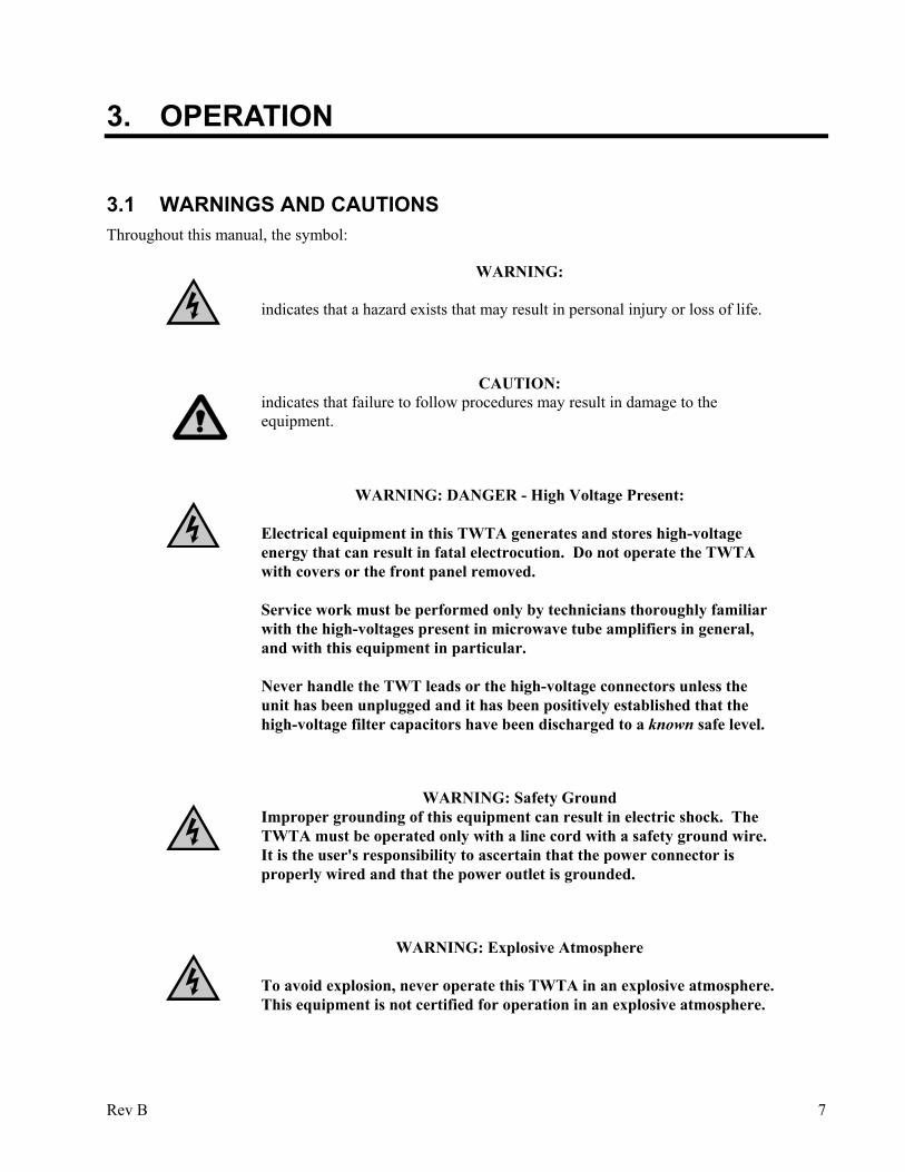
3.1 WARNINGS AND CAUTIONS Throughout this manual, the symbol:
WARNING:
indicates that a hazard exists that may result in personal injury or loss of life.
CAUTION: indicates that failure to follow procedures may result in damage to the
equipment.
WARNING: DANGER - High Voltage Present:
Electrical equipment in this TWTA generates and stores high-voltage energy that can result in fatal electrocution. Do not operate the TWTA with covers or the front panel removed. Service work must be performed only by technicians thoroughly familiar with the high-voltages present in microwave tube amplifiers in general, and with this equipment in particular. Never handle the TWT leads or the high-voltage connectors unless the unit has been unplugged and it has been positively established that the high-voltage filter capacitors have been discharged to a known safe level.
WARNING: Safety Ground Improper grounding of this equipment can result in electric shock. The
TWTA must be operated only with a line cord with a safety ground wire. It is the user's responsibility to ascertain that the power connector is properly wired and that the power outlet is grounded.
WARNING: Explosive Atmosphere
To avoid explosion, never operate this TWTA in an explosive atmosphere. This equipment is not certified for operation in an explosive atmosphere.
Rev B 7
Model 20T4G18
3.2 INSTALLATION
3.2.1 Unpacking
Upon receiving the TWTA, unpack the unit and inspect it for obvious signs of external damage. If damage is observed, notify the carrier and contact an authorized service representative.
Save and store the shipping container in case the unit needs to be returned in the future for calibration or repair.
3.2.2 Mounting
The TWTA may be operated as a standalone benchtop unit, or it may be installed in a 19" rack.
If rack mounting is desired, first remove the amplifier from the cabinet, then install the amplifier in the rack.
CAUTION: Due to the weight of the unit, the removal of the amplifier from the
cabinet or rack is a two person operation.
Before removal disconnect power, RF, and any other interface connectors. On the rear of the unit, remove the six screws used to connect brackets to amplifier. On the front of the unit, remove the four screws holding the front panel to the cabinet. Carefully slide the amplifier out of the front of the cabinet.
CAUTION:
Never rack mount the TWTA using the front panel alone. The chassis is likely to be damaged unless its weight is supported. Bottom support rails must be provided in a rack mount configuration.
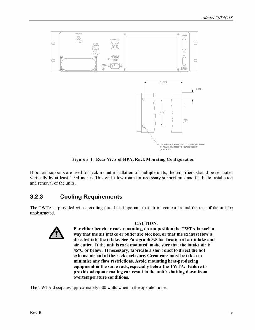
See Figure 3-1 (on the next page) for the locations of threaded holes which may be used for supplementary support of the rear of the TWTA.
8 Rev B
Model 20T4G18
USE 8-32 FH SCREWS, 3/8-1/2" THREAD IN CABINETTO ATTACH REAR SUPPORT BRACKETS HERE (BOTH SIDES)
100-255 VAC
SAFETYGROUND
50/60 HZ.500 VA
EXTERNALINTERLOCK
RF INPUT0 DBM MAX
RF OUTPUT
TYPE TNC
RF SAMPLE OUT
AC POWER IN
IEEE-488
23.675
0.865
3.50
Figure 3-1. Rear View of HPA, Rack Mounting Configuration
If bottom supports are used for rack mount installation of multiple units, the amplifiers should be separated vertically by at least 1 3/4 inches. This will allow room for necessary support rails and facilitate installation and removal of the units.
3.2.3 Cooling Requirements
The TWTA is provided with a cooling fan. It is important that air movement around the rear of the unit be unobstructed.
CAUTION: For either bench or rack mounting, do not position the TWTA in such a
way that the air intake or outlet are blocked, or that the exhaust flow is directed into the intake. See Paragraph 3.5 for location of air intake and air outlet. If the unit is rack mounted, make sure that the intake air is 45°C or below. If necessary, fabricate a short duct to direct the hot exhaust air out of the rack enclosure. Great care must be taken to minimize any flow restrictions. Avoid mounting heat-producing equipment in the same rack, especially below the TWTA. Failure to provide adequate cooling can result in the unit's shutting down from overtemperature conditions.
The TWTA dissipates approximately 500 watts when in the operate mode.
Rev B 9
Model 20T4G18
3.2.4 AC Line Power Connections
AC line power connection to the TWTA is made at the AC inlet J1, which is a female IEC-320 connector. A line cord suitable for the type of AC outlet used, and consistent with local electrical codes, must be obtained to mate with J1. Minimum wire size for the line cord is 18 gauge.
TWTAs destined for the North American market are provided with a terminated 3-wire cord. It plugs into normal 120 VAC single phase outlets. The amplifier will operate from any line voltage between 99 and 260 VAC.
3.2.5 RF Output Connections
The RF output coaxial connector is type TNC female.
CAUTION: Never operate the TWTA without a matched output load rated for at least
100 watts, continuous. The TWTA is not provided with an output isolator. Full reflected power may irreparably damage the TWT. Even with no drive, “looping” oscillation can result in RF output high enough to damage the tube if it is operated without a load. The VSWR detection and foldback circuit is provided to protect the tube from progressive failure or mismatch of the output load; it should not be relied on for protection from the absence of a load.
If an external isolator is installed at the output of the TWTA, either the isolator should have a load capable of dissipating the full output of the TWTA or the isolator load should be provided with a temperature sensing switch. The temperature switch should be normally closed, self-resetting, and with a temperature rating such that there is no possibility of damaging the load by overheating before the switch opens. The TWTA may be interlocked with the switch by connecting it between pins 3 and 4 of the external interlock connector (J2). If no external isolator is used, install a jumper between pins 3 and 4. See section 3.2.6, External Interlock Connector, below.
3.2.6 External Interlock Connector
The TWTA is provided with an external interlock capability via a 15-pin female D-sub connector, J2. To enable the high voltage power supply, it is necessary to provide continuity between J2 pins 3 and 4. If the amplifier shuts down because the interlock was opened, it will be necessary to reset the system to return to standby (see System shutdown screen in Section 3.4). There is an internal jumper between J2 pins 1 and 2; a continuity check through these pins can be used to verify the presence of the amplifier in the instrumentation system. Users may adopt this interlock feature to disable the RF output for either equipment protection or as a backup for personnel protection.
CAUTION: Do not rely on the external interlock for personnel protection. The intent
of the external interlock feature is to disable the RF output for equipment protection. Use proper operating and safety procedures to insure that power is removed for personnel safety.
10 Rev B
Model 20T4G18
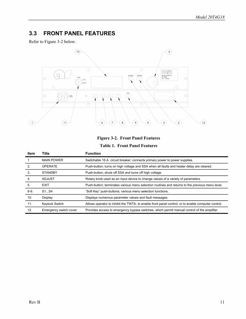
3.3 FRONT PANEL FEATURES Refer to Figure 3-2 below.
STANDBY
1 11 6 7 8
POWERMAIN
INHIBIT
REMOTE
LOCAL
EXIT
10
129 5 3 2
Model 20T4G1820 Watts4.2 - 18 GHz
OPERATE
4
Figure 3-2. Front Panel Features
Table 1. Front Panel Features
Item Title Function
1 MAIN POWER Switchable 16 A. circuit breaker; connects primary power to power supplies.
2. OPERATE Push-button; turns on high voltage and SSA when all faults and heater delay are cleared.
3. STANDBY Push-button; shuts off SSA and turns off high voltage.
4. ADJUST Rotary knob used as an input device to change values of a variety of parameters.
5. EXIT Push-button; terminates various menu selection routines and returns to the previous menu level.
6-9. S1...S4 “Soft Key” push-buttons; various menu selection functions.
10. Display Displays numerous parameter values and fault messages.
11. Keylock Switch Allows operator to inhibit the TWTA, to enable front panel control, or to enable computer control.
12. Emergency switch cover Provides access to emergency bypass switches, which permit manual control of the amplifier.
Rev B 11
Model 20T4G18
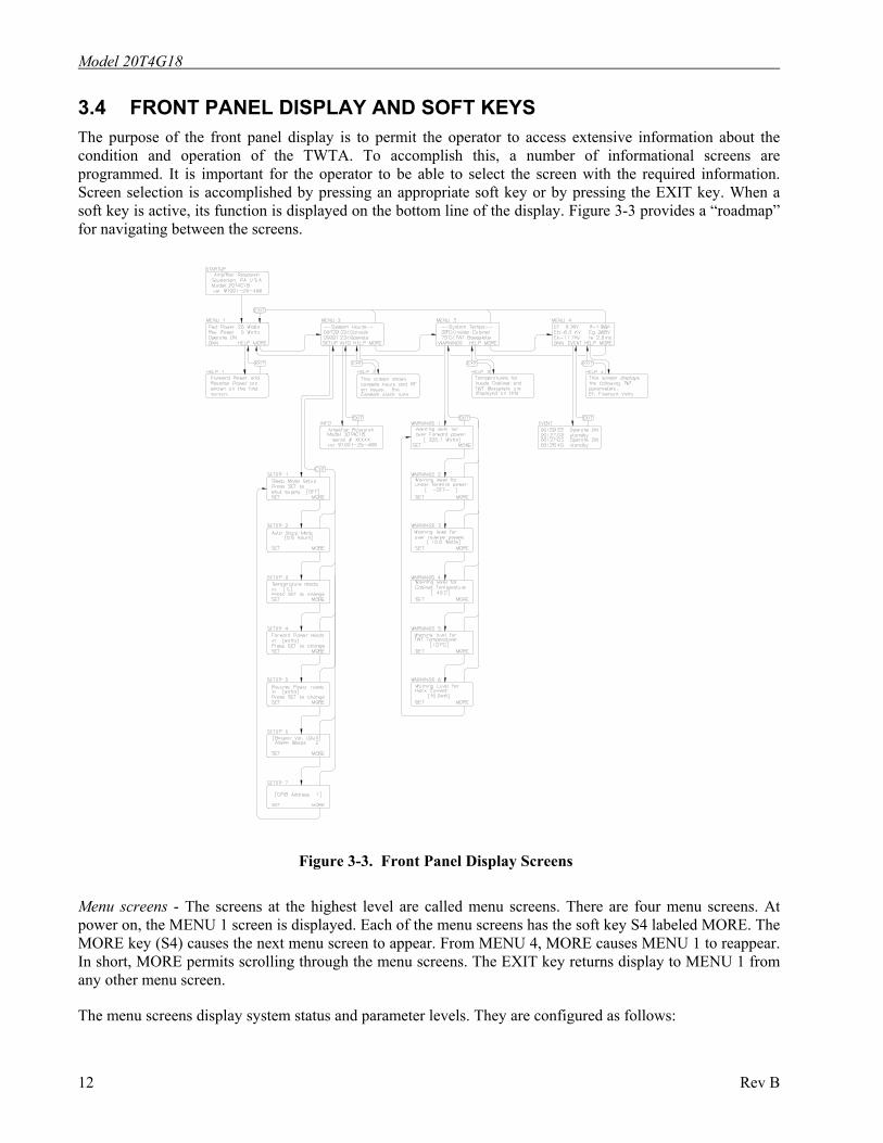
3.4 FRONT PANEL DISPLAY AND SOFT KEYS The purpose of the front panel display is to permit the operator to access extensive information about the condition and operation of the TWTA. To accomplish this, a number of informational screens are programmed. It is important for the operator to be able to select the screen with the required information. Screen selection is accomplished by pressing an appropriate soft key or by pressing the EXIT key. When a soft key is active, its function is displayed on the bottom line of the display. Figure 3-3 provides a “roadmap” for navigating between the screens.
Figure 3-3. Front Panel Display Screens
Menu screens - The screens at the highest level are called menu screens. There are four menu screens. At power on, the MENU 1 screen is displayed. Each of the menu screens has the soft key S4 labeled MORE. The MORE key (S4) causes the next menu screen to appear. From MENU 4, MORE causes MENU 1 to reappear. In short, MORE permits scrolling through the menu screens. The EXIT key returns display to MENU 1 from any other menu screen.
The menu screens display system status and parameter levels. They are configured as follows:
12 Rev B
Model 20T4G18
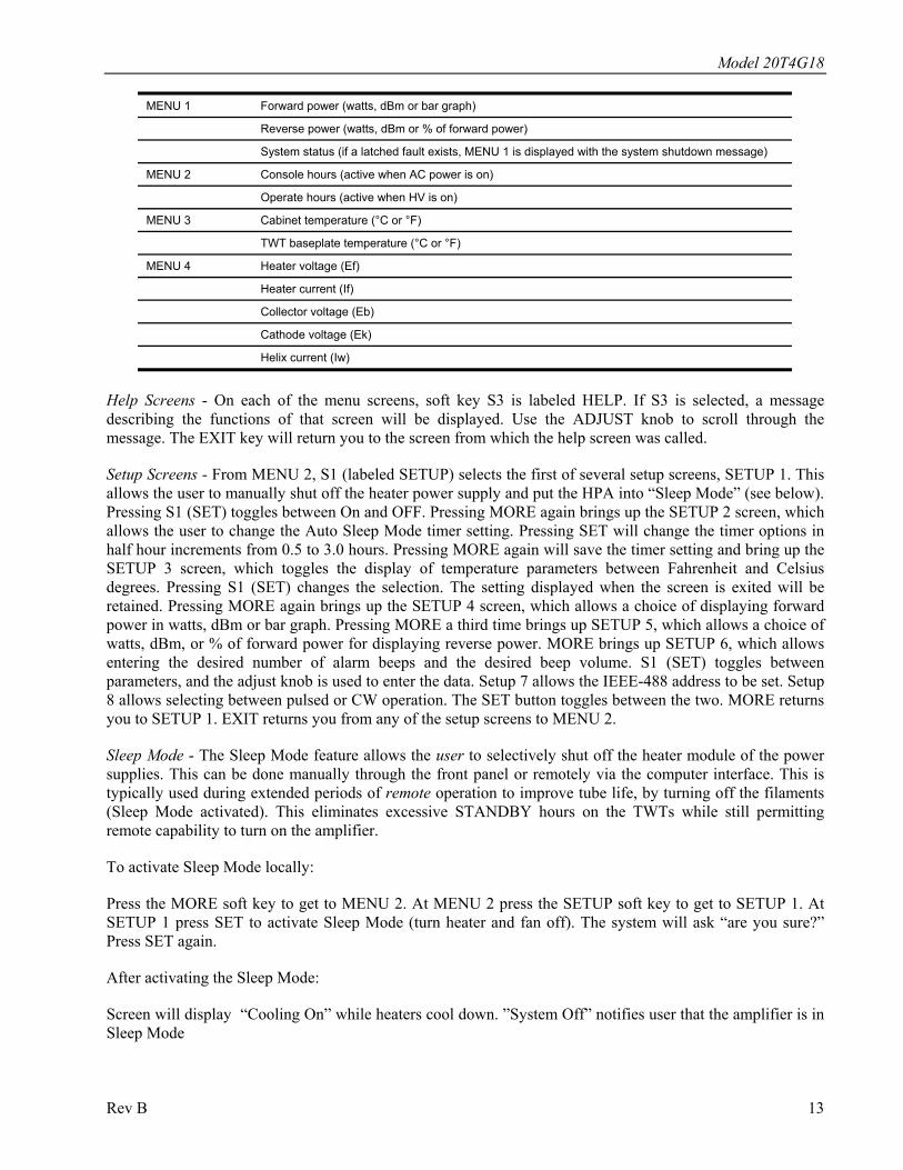
MENU 1 Forward power (watts, dBm or bar graph)
Reverse power (watts, dBm or % of forward power)
System status (if a latched fault exists, MENU 1 is displayed with the system shutdown message)
MENU 2 Console hours (active when AC power is on)
Operate hours (active when HV is on)
MENU 3 Cabinet temperature (°C or °F)
TWT baseplate temperature (°C or °F)
MENU 4 Heater voltage (Ef)
Heater current (If)
Collector voltage (Eb)
Cathode voltage (Ek)
Helix current (Iw)
Help Screens - On each of the menu screens, soft key S3 is labeled HELP. If S3 is selected, a message describing the functions of that screen will be displayed. Use the ADJUST knob to scroll through the message. The EXIT key will return you to the screen from which the help screen was called.
Setup Screens - From MENU 2, S1 (labeled SETUP) selects the first of several setup screens, SETUP 1. This allows the user to manually shut off the heater power supply and put the HPA into “Sleep Mode” (see below). Pressing S1 (SET) toggles between On and OFF. Pressing MORE again brings up the SETUP 2 screen, which allows the user to change the Auto Sleep Mode timer setting. Pressing SET will change the timer options in half hour increments from 0.5 to 3.0 hours. Pressing MORE again will save the timer setting and bring up the SETUP 3 screen, which toggles the display of temperature parameters between Fahrenheit and Celsius degrees. Pressing S1 (SET) changes the selection. The setting displayed when the screen is exited will be retained. Pressing MORE again brings up the SETUP 4 screen, which allows a choice of displaying forward power in watts, dBm or bar graph. Pressing MORE a third time brings up SETUP 5, which allows a choice of watts, dBm, or % of forward power for displaying reverse power. MORE brings up SETUP 6, which allows entering the desired number of alarm beeps and the desired beep volume. S1 (SET) toggles between parameters, and the adjust knob is used to enter the data. Setup 7 allows the IEEE-488 address to be set. Setup 8 allows selecting between pulsed or CW operation. The SET button toggles between the two. MORE returns you to SETUP 1. EXIT returns you from any of the setup screens to MENU 2.
Sleep Mode - The Sleep Mode feature allows the user to selectively shut off the heater module of the power supplies. This can be done manually through the front panel or remotely via the computer interface. This is typically used during extended periods of remote operation to improve tube life, by turning off the filaments (Sleep Mode activated). This eliminates excessive STANDBY hours on the TWTs while still permitting remote capability to turn on the amplifier.
To activate Sleep Mode locally:
Press the MORE soft key to get to MENU 2. At MENU 2 press the SETUP soft key to get to SETUP 1. At SETUP 1 press SET to activate Sleep Mode (turn heater and fan off). The system will ask “are you sure?” Press SET again.
After activating the Sleep Mode:
Screen will display “Cooling On” while heaters cool down. ”System Off” notifies user that the amplifier is in Sleep Mode
Rev B 13
Model 20T4G18 To deactivate Sleep Mode locally:
Press the ON soft key to de-activate Sleep Mode. Amplifier will return to MENU 1. When de-activating the Sleep Mode the heaters will require approximately a 5 minute heater time delay. Wait the full 5 minutes prior to selecting OPERATE.
For remote activation of Sleep Mode or to set the Auto Sleep Mode timer remotely see Table 3 in Section 3.8.
Warnings Screens - From MENU 3, S1 (labeled WARNINGS) selects WARNINGS 1 which allows the operator to enter the maximum forward power. The existing value is between brackets[]; pressing SET puts arrows >< around the value, indicating that the adjust knob is active. The effect of the warning setpoint is as follows: if the forward power exceeds the setpoint, the audible alarm will sound (if configured in SETUP 3).
This warning will be repeated every thirty seconds until the over forward power condition is cleared. In addition, a warning message will appear on line 3 (the status line) of MENU 1. In the event that the alarm is heard, the operator should go to MENU 1 to determine the cause.
Pressing more brings up WARNINGS 2, which allows the under forward power setpoint to be entered. Adjusting this to the minimum value causes -OFF- to be selected, disabling this alarm.
In WARNINGS 3, the maximum reverse power level is set. Note that these are warning levels at which the beep sounds; the actual maximum reverse power level that generates a system fault is set in hardware in the TWT power supply HPA Logic and Control module (A16485).
MORE brings up WARNINGS 4, which allows input of the maximum cabinet temperature. Entering this parameter is performed as above.
MORE brings up WARNINGS 5, identical to the previous screen except that it deals with the maximum TWT collector block temperature. If either parameter exceeds the setpoint, the audible alarm will sound every 30 seconds (if configured), and a warning message will appear on line 3 of MENU 1.
From WARNINGS 5, MORE brings up WARNINGS 6, which permits setting the maximum helix current. Any helix current above this setpoint will result in an audible alarm (if configured), repeated every 30 seconds; and a warning message is displayed on the status line of MENU 1.
Pressing MORE again returns display to WARNINGS 1. As before, pressing EXIT from any of the warnings screens returns display to MENU 3.
Info Screen - From MENU 2, S2 (labeled INFO) selects a screen that displays the RF sample port calibration factors at various frequencies across the band. In addition, this screen displays the model number, serial number and firmware revision information which may be required by a service representative when providing technical assistance. The EXIT key returns the display to MENU 2.
Event Screen - From MENU 4, S2 (labeled EVENT) provides a display of events logged by the control system. These events include AC power-up, heater warm-up, change from standby to operate, faults, and resets. The events are stored in a first-in-first-out (FIFO) software buffer that has room for 100 events; as new events are logged, the older ones are discarded.
System Shutdown Screen - In the event of a system shutdown due to a latched fault (i. e., a fault such as body overcurrent or power low line that requires a reset), the MENU screen is replaced by a screen indicating the nature of the fault. Softkey S4 (labeled OK) is implemented as a reset key; pressing S4 brings back the MENU screens. Line 3 of MENU 1, which normally displays the operational state of the TWTA, is used as a fault display line until the fault is cleared. When the fault clears the system will automatically resume the standby state and high voltage on will be enabled once again.
14 Rev B
Model 20T4G18
Factory Service Screens - A number of screens intended for factory service and calibration are behind passwords and are not accessible to the user.
System Malfunction Screens - A number of screens are reserved to display error messages. These messages are not normally seen and indicate a malfunction of the TWTA. System malfunction messages include the following:
Database corrupt Communication failure Cannot restore CU line voltage too low to operate. System shutdown
In the event that one of these appears, shut off the TWTA and contact an authorized service representative before proceeding.
CAUTION: Attempts to operate the TWTA despite control unit problems may result
in loss of the static RAM database and calibration information.
Rev B 15
Model 20T4G18
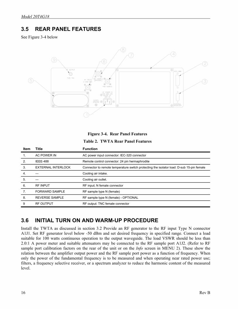
3.5 REAR PANEL FEATURES See Figure 3-4 below
Figure 3-4. Rear Panel Features
Table 2. TWTA Rear Panel Features
Item Title Function
1. AC POWER IN AC power input connector: IEC-320 connector
2. IEEE-488 Remote control connector: 24 pin hermaphrodite
3. EXTERNAL INTERLOCK Connector to remote temperature switch protecting the isolator load: D-sub 15-pin female
4. — Cooling air intake.
5. — Cooling air outlet.
6. RF INPUT RF input; N female connector
7. FORWARD SAMPLE RF sample type N (female)
8. REVERSE SAMPLE RF sample type N (female) - OPTIONAL
9 RF OUTPUT RF output: TNC female connector
3.6 INITIAL TURN ON AND WARM-UP PROCEDURE Install the TWTA as discussed in section 3.2 Provide an RF generator to the RF input Type N connector A1J1. Set RF generator level below -50 dBm and set desired frequency in specified range. Connect a load suitable for 100 watts continuous operation to the output waveguide. The load VSWR should be less than 2.0:1 A power meter and suitable attenuators may be connected to the RF sample port A1J2. (Refer to RF sample port calibration factors on the rear of the unit or on the Info screen in MENU 2). These show the relation between the amplifier output power and the RF sample port power as a function of frequency. When only the power of the fundamental frequency is to be measured and when operating near rated power use; filters, a frequency selective receiver, or a spectrum analyzer to reduce the harmonic content of the measured level.
16 Rev B
Model 20T4G18
Set keylock to LOCAL.
Switch on the MAIN POWER circuit breaker. The fan will operate. The front panel display will show several identification messages and then the MENU 1 screen. The third line will indicate that the heater time delay is active.
Allow the heater warm-up delay to expire. Line three will indicate OFF/READY.
Push S4 (MORE) three times to go to MENU 4. Verify that the heater voltage and current are near their nominal levels. The values of these parameters at the time the TWTA left the factory are logged on the test data sheet.
Push the OPERATE push-button. You will now see the cathode and the collector voltages rise. Verify that the collector and cathode voltages are near nominal. The helix current should be close to the nominal value for no RF drive. Then push MORE or EXIT to go back to MENU 1.
Set the TWTA gain to maximum. Adjust the RF generator to slowly increase the RF drive toward 0 dBm to reach the desired FWD PWR on the display and power meter (connected to sample port). The forward power bar graph will become active, with maximum length when peak power output is achieved. Best performance is obtained when the input RF drive is set at or just below the level which causes peak power output. Do not set input drive above 0 dBm (Input drive above +20 dBm may damage the unit).The reverse power level should remain below 10% of the forward power, assuming that the load is properly matched.
An alternate procedure is to pre-set the TWTA gain to minimum, set the RF generator to 0 dBm and then slowly increase the TWTA gain to set the desired RF output level.
Observe that the helix current is sensitive to the RF drive level of the TWT. It is at a minimum with no RF drive. The helix currents with no drive and with rated RF output mid-band are logged on the test data sheet. The value of the helix current is a good qualitative indicator of RF drive present.
To shut the system down, turn down the RF generator level below -50 dBm and press STANDBY. Allow the TWTA to cool down until the TWT temperature drops below 70°C, then turn off main power
3.7 EMERGENCY BYPASS OPERATION For reference, see schematic 10-24830-002 in section 5.2.
The TWTA is provided with a means of operating the amplifier manually in the event that there is a failure of the control module and it is imperative that the amplifier remain on line.
CAUTION: Emergency bypass operation disables certain protective and diagnostic
features. For this reason, the emergency bypass mode of operation should be used only when the control unit fails and when it is essential to remain on line.
To access the manual controls, remove the two 4-40 screws securing the emergency switch cover on the front panel. Emergency bypass mode is selected by pushing the left-hand switch (S1) to the left. The center switch (S2) toggles between high voltage on (left) and high voltage off (right). The right-hand switch (S3) selects between solid state amplifier (SSA) active (RF on) in the left hand position, and SSA off (RF off) in the right-hand position. There is a manual control for the gain adjustment as well. This is a flat, square single-turn pot (R1).
Rev B 17
Model 20T4G18
CAUTION: Do not adjust 20-turn pot R11; its function is to set the foldback RF
output level, and it is calibrated at the factory.
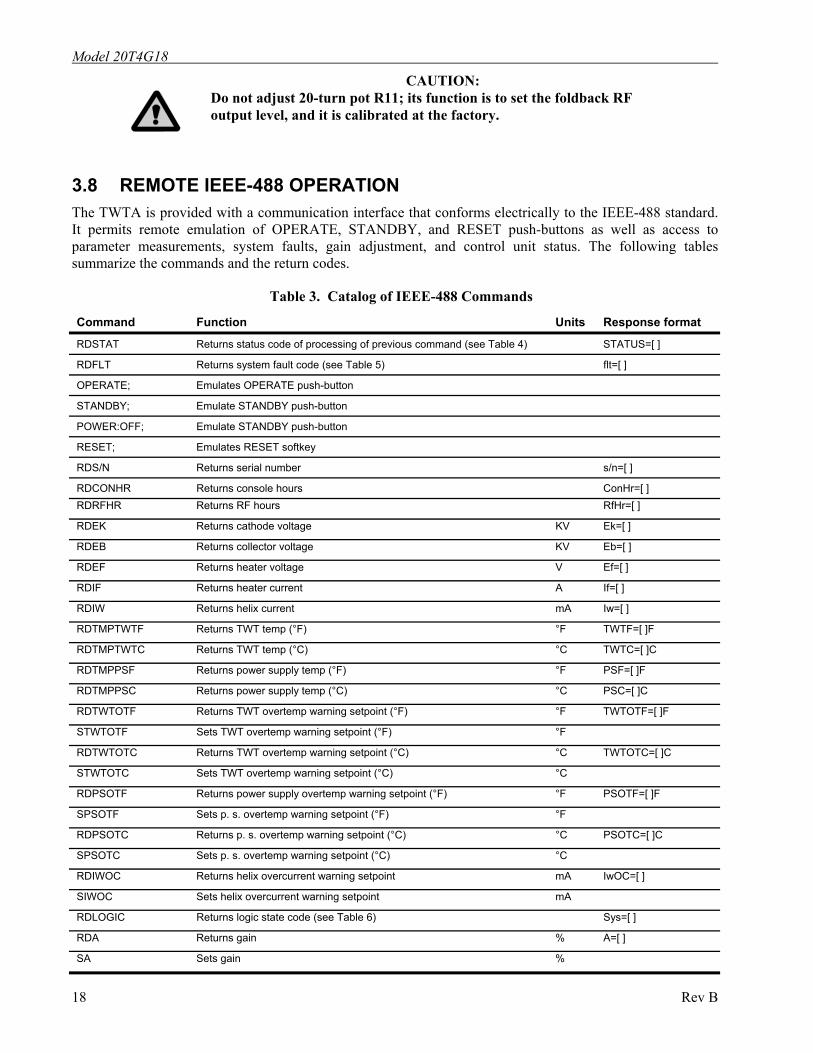
3.8 REMOTE IEEE-488 OPERATION The TWTA is provided with a communication interface that conforms electrically to the IEEE-488 standard. It permits remote emulation of OPERATE, STANDBY, and RESET push-buttons as well as access to parameter measurements, system faults, gain adjustment, and control unit status. The following tables summarize the commands and the return codes.
Table 3. Catalog of IEEE-488 Commands
18 Rev B
Command Function Units Response format
RDSTAT Returns status code of processing of previous command (see Table 4) STATUS=[ ]
RDFLT Returns system fault code (see Table 5) flt=[ ]
OPERATE; Emulates OPERATE push-button
STANDBY; Emulate STANDBY push-button
POWER:OFF; Emulate STANDBY push-button
RESET; Emulates RESET softkey
RDS/N Returns serial number s/n=[ ]
RDCONHR Returns console hours ConHr=[ ] RDRFHR Returns RF hours RfHr=[ ]
RDEK Returns cathode voltage KV Ek=[ ]
RDEB Returns collector voltage KV Eb=[ ]
RDEF Returns heater voltage V Ef=[ ]
RDIF Returns heater current A If=[ ]
RDIW Returns helix current mA Iw=[ ]
RDTMPTWTF Returns TWT temp (°F) °F TWTF=[ ]F
RDTMPTWTC Returns TWT temp (°C) °C TWTC=[ ]C
RDTMPPSF Returns power supply temp (°F) °F PSF=[ ]F
RDTMPPSC Returns power supply temp (°C) °C PSC=[ ]C
RDTWTOTF Returns TWT overtemp warning setpoint (°F) °F TWTOTF=[ ]F
STWTOTF Sets TWT overtemp warning setpoint (°F) °F
RDTWTOTC Returns TWT overtemp warning setpoint (°C) °C TWTOTC=[ ]C
STWTOTC Sets TWT overtemp warning setpoint (°C) °C
RDPSOTF Returns power supply overtemp warning setpoint (°F) °F PSOTF=[ ]F
SPSOTF Sets p. s. overtemp warning setpoint (°F) °F
RDPSOTC Returns p. s. overtemp warning setpoint (°C) °C PSOTC=[ ]C
SPSOTC Sets p. s. overtemp warning setpoint (°C) °C
RDIWOC Returns helix overcurrent warning setpoint mA IwOC=[ ]
SIWOC Sets helix overcurrent warning setpoint mA
RDLOGIC Returns logic state code (see Table 6) Sys=[ ]
RDA Returns gain % A=[ ]
SA Sets gain %
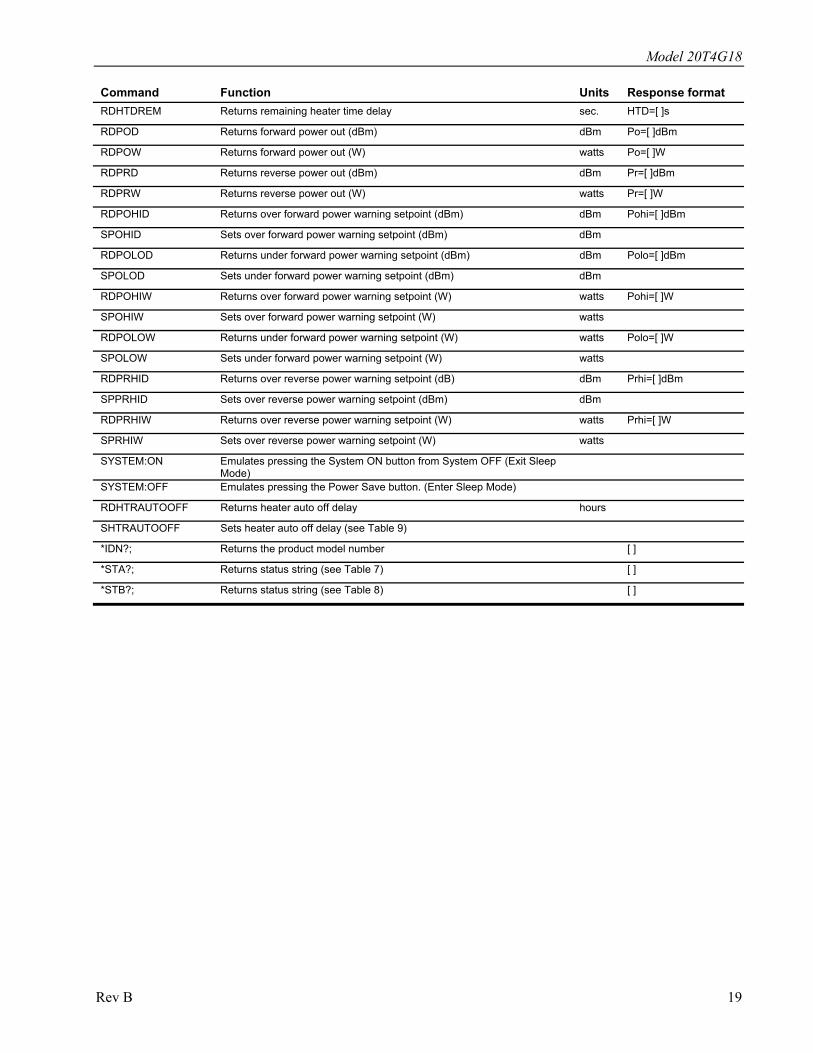
Model 20T4G18
Command Function Units Response format RDHTDREM Returns remaining heater time delay sec. HTD=[ ]s
RDPOD Returns forward power out (dBm) dBm Po=[ ]dBm
RDPOW Returns forward power out (W) watts Po=[ ]W
RDPRD Returns reverse power out (dBm) dBm Pr=[ ]dBm
RDPRW Returns reverse power out (W) watts Pr=[ ]W
RDPOHID Returns over forward power warning setpoint (dBm) dBm Pohi=[ ]dBm
SPOHID Sets over forward power warning setpoint (dBm) dBm
RDPOLOD Returns under forward power warning setpoint (dBm) dBm Polo=[ ]dBm
SPOLOD Sets under forward power warning setpoint (dBm) dBm
RDPOHIW Returns over forward power warning setpoint (W) watts Pohi=[ ]W
SPOHIW Sets over forward power warning setpoint (W) watts
RDPOLOW Returns under forward power warning setpoint (W) watts Polo=[ ]W
SPOLOW Sets under forward power warning setpoint (W) watts
RDPRHID Returns over reverse power warning setpoint (dB) dBm Prhi=[ ]dBm
SPPRHID Sets over reverse power warning setpoint (dBm) dBm
RDPRHIW Returns over reverse power warning setpoint (W) watts Prhi=[ ]W
SPRHIW Sets over reverse power warning setpoint (W) watts
SYSTEM:ON Emulates pressing the System ON button from System OFF (Exit Sleep Mode)
SYSTEM:OFF Emulates pressing the Power Save button. (Enter Sleep Mode)
RDHTRAUTOOFF Returns heater auto off delay hours
SHTRAUTOOFF Sets heater auto off delay (see Table 9)
*IDN?; Returns the product model number [ ]
*STA?; Returns status string (see Table 7) [ ]
*STB?; Returns status string (see Table 8) [ ]
Rev B 19
Model 20T4G18
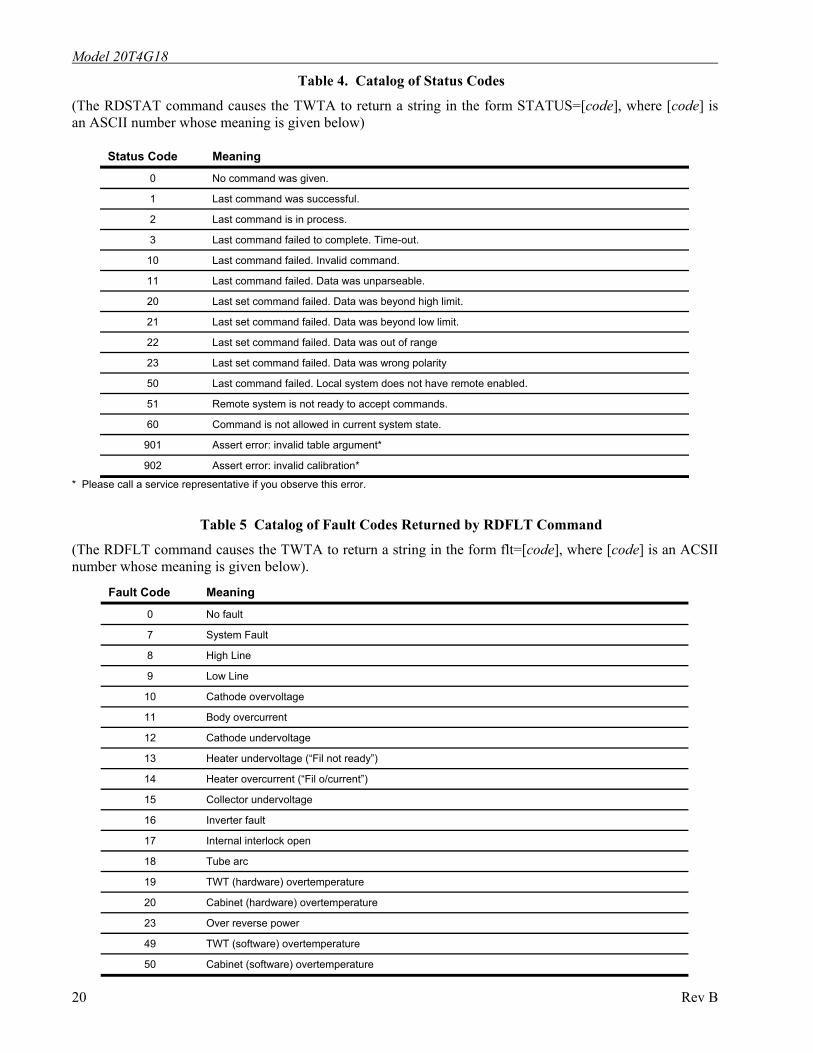
Table 4. Catalog of Status Codes
(The RDSTAT command causes the TWTA to return a string in the form STATUS=[code], where [code] is an ASCII number whose meaning is given below)
Status Code Meaning
0 No command was given.
1 Last command was successful.
2 Last command is in process.
3 Last command failed to complete. Time-out.
10 Last command failed. Invalid command.
11 Last command failed. Data was unparseable.
20 Last set command failed. Data was beyond high limit.
21 Last set command failed. Data was beyond low limit.
22 Last set command failed. Data was out of range
23 Last set command failed. Data was wrong polarity
50 Last command failed. Local system does not have remote enabled.
51 Remote system is not ready to accept commands.
60 Command is not allowed in current system state.
901 Assert error: invalid table argument*
902 Assert error: invalid calibration*
* Please call a service representative if you observe this error.
Table 5 Catalog of Fault Codes Returned by RDFLT Command
(The RDFLT command causes the TWTA to return a string in the form flt=[code], where [code] is an ACSII number whose meaning is given below).
Fault Code Meaning
0 No fault
7 System Fault
8 High Line
9 Low Line
10 Cathode overvoltage
11 Body overcurrent
12 Cathode undervoltage
13 Heater undervoltage (“Fil not ready”)
14 Heater overcurrent (“Fil o/current”)
15 Collector undervoltage
16 Inverter fault
17 Internal interlock open
18 Tube arc
19 TWT (hardware) overtemperature
20 Cabinet (hardware) overtemperature
23 Over reverse power
49 TWT (software) overtemperature
50 Cabinet (software) overtemperature
20 Rev B
Model 20T4G18
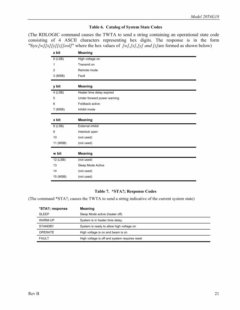
Table 6. Catalog of System State Codes
(The RDLOGIC command causes the TWTA to send a string containing an operational state code consisting of 4 ASCII characters representing hex digits. The response is in the form "Sys:[w][x][y][z][eol]" where the hex values of [w],[x],[y] and [z]are formed as shown below)
z bit Meaning 0 (LSB) High voltage on
1 Transmit on
2 Remote mode
3 (MSB) Fault
y bit Meaning 4 (LSB) Heater time delay expired
5 Under forward power warning
6 Foldback active
7 (MSB) Inhibit mode
x bit Meaning 8 (LSB) External inhibit
9 Interlock open
10 (not used)
11 (MSB) (not used)
w bit Meaning 12 (LSB) (not used)
13 Sleep Mode Active
14 (not used)
15 (MSB) (not used)
Table 7. *STA?; Response Codes
(The command *STA?; causes the TWTA to send a string indicative of the current system state)
*STA?; response Meaning SLEEP Sleep Mode active (heater off)
WARM-UP System is in heater time delay.
STANDBY System is ready to allow high voltage on
OPERATE High voltage is on and beam is on
FAULT High voltage is off and system requires reset
Rev B 21
Model 20T4G18
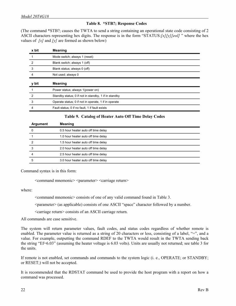
Table 8. *STB?; Response Codes
(The command *STB?; causes the TWTA to send a string containing an operational state code consisting of 2 ASCII characters representing hex digits. The response is in the form “STATUS:[x][y][eol] ” where the hex values of [x] and [y] are formed as shown below)
x bit Meaning
1 Mode switch; always 1 (reset)
2 Blank switch; always 1 (off)
3 Blank status; always 0 (off)
4 Not used; always 0
y bit Meaning
1 Power status; always 1(power on)
2 Standby status; 0 if not in standby, 1 if in standby
3 Operate status; 0 if not in operate, 1 if in operate
4 Fault status; 0 if no fault, 1 if fault exists
Table 9. Catalog of Heater Auto Off Time Delay Codes
Argument Meaning
0 0.5 hour heater auto off time delay
1 1.0 hour heater auto off time delay
2 1.5 hour heater auto off time delay
3 2.0 hour heater auto off time delay
4 2.5 hour heater auto off time delay
5 3.0 hour heater auto off time delay
Command syntax is in this form:
<command mnemonic> <parameter> <carriage return>
where:
<command mnemonic> consists of one of any valid command found in Table 3.
<parameter> (as applicable) consists of one ASCII “space” character followed by a number.
<carriage return> consists of an ASCII carriage return.
All commands are case sensitive.
The system will return parameter values, fault codes, and status codes regardless of whether remote is enabled. The parameter value is returned as a string of 20 characters or less, consisting of a label, “=”, and a value. For example, outputting the command RDEF to the TWTA would result in the TWTA sending back the string “Ef=6.03” (assuming the heater voltage is 6.03 volts). Units are usually not returned; see table 3 for the units.
If remote is not enabled, set commands and commands to the system logic (i. e., OPERATE; or STANDBY; or RESET;) will not be accepted.
It is recommended that the RDSTAT command be used to provide the host program with a report on how a command was processed.
22 Rev B
Model 20T4G18
A small sample program that can send commands and receive the strings returned by the TWTA is included in section 5.6. It is written in Hewlett-Packard's “Rocky Mountain” BASIC. The program assumes that the IEEE-488 bus is at address 7 and that the address of the TWTA is 01.
Remote operation is determined by the application (software) program in the system controller. This application program will aid the user in generating the Command Codes and displaying/monitoring the Status Codes. Consult the application program users instructions for Remote operation procedure.
The application program should issue only one string at a time. After each functional command is issued the status should be checked to ensure that the command has been properly executed. The application program should allow sufficient time for the function to be completed before checking the status.
The application program should facilitate checking the status just prior to issuing a command, since the status could have been changed by a fault condition of the amplifier or by operator activation of the amplifier. Periodic checking of the status is also recommended.
3.9 TWTA GENERAL CONSIDERATIONS This section is intended to offer some guidelines regarding operation, storage and use of Amplifier Research TWTAs.
Storage: TWTAs, as with other electronic equipment, are best stored in a benign environment at reasonably constant temperature. Service life is not improved by periodic operation.
Availability: For critical missions, and after long periods of storage, it is recommended that TWTA operation be checked sufficiently in advance of the mission to permit repair if required. Though service life is not improved by periodic operation, users experiencing amplifier trip due to body over current may benefit by periodically operating a unit with high voltage and grid on, but no RF drive. Such operation for about one hour on a weekly basis should effectively reduce nuisance tripping. Since the cathode structure has finite life, extended periods of non-functional operation of TWTAs is not recommended. An alternate approach, if periodic trip off has been observed, is to operate the unit without RF input for 1-2 hours before planned functional operation, resetting the unit after occasional trip off.
Cooling during Operate Mode: AR TWTAs have their air outlets and inlets on the rear panels. It is important to prevent the heated air, which is expelled from the TWTA’s air outlets, from being recycled into the air inlets. Applications should have a clearance behind the TWTA of at least two feet for single bench top units and at least three feet for the higher power units, or the heated air should be ducted away.
Operation in Standby Mode: Standby mode for TWTAs readies the unit for operation. In this mode the filaments are on but the high voltage is off. TWTAs should not be left in this Standby mode for extended periods. Where practical, operational procedures should limit the time on Standby mode to less than approximately one hour. (See Explanation of…., below)
Operate Turn on: When selecting the Operate mode, when high voltage is first turned on, there may be some internal TWT arcing which can cause protective circuits to deselect the Operate mode, thereby returning the unit to the Standby mode. There may be a report of body over-current fault. In either case, if there is no other contraindication, the Operate mode may be selected again. This procedure maybe repeated, if needed up to 25 times, until the Operate mode is actually set. If this condition persists, contact Amplifier Research Service for additional assistance. (See Explanation of…, below)
Noise Power Density (NPD): TWTAs produce rf noise over their operating frequency range, as specified by the Noise Power Density (NPD). This noise is significantly higher than the noise produced by typical solid
Rev B 23
Model 20T4G18 state amplifiers, and is inherent in present TWTAs. The noise may surprise users new to TWTAs when it accumulates and results in a significant indication in a broadband measurement device – such as a power meter or field probe. The error produced by this indication is not significant when operating near rated TWTA power levels, but may cause difficulty when trying to operate high power TWTAs at low output power levels.
For example, consider a hypothetical typical NPD of –76 dBm/Hz, from a 4 GHz bandwidth amplifier. A broadband detector might see the NPD as [-76 dBm/Hz + 10 (log 4 x 10⁹) BW factor = -76 + 96=] +20 dBm, or 0.1 watts. This power is insignificant for a user operating at 200 watts (+53 dBm), but may be very noticeable to a user trying to operate below 1 watt (+30 dBm). [One watt is 0.5% of (23dB below) rated power for a 200 watt amplifier.] A field probe user who obtains a 200 V/M field with 200 watts, may see a field as high as [53dBm – 20dBm = 33dB below 200 V/M=] 4.5 V/M due to this hypothetical NPD.
For these applications the use of a lower power amplifier is highly recommended, especially when considering safety issues. Alternatively, additional power loss in the form of an added high power microwave attenuator, or preferably an increased space loss for radiated fields, may be used to lower the noise received by the broadband measurement device.
Explanation of Limiting the Time in Standby mode and of Repeated Operate Selection.
Traveling wave tubes tend to get “gassy” if they are left in a “Standby” mode for extended periods of time. In this “Standby” mode, the heater (filament) is on but there is no high voltage applied to the collector (or high voltage is applied to the collector but the grid is off). This is the normal state after a tube’s warm up time, just prior to entering the “Operate” mode.
In this state the cathode end of the TWT is heating up but the electron “Beam” is off. In other words, there is no cathode current. As the cathode heats up, gas trapped in the structure of the tube can be released, thus corrupting the vacuum of the tube. If the tube become too “gassy”, arcing may occur when the high voltage is fully applied in the “Operate” mode. Another possible failure mode is a body over-current fault when the beam is turned on and the tube is “gassy”.
Occasional arcing is normal for a TWT. The support components are designed to handle this, protecting both the TWT and its support circuitry. However, if the tube arcs two or three times in rapid succession, or worse yet repeatedly, a fault will be sensed that will shut the high voltage off, thus removing the unit from “Operate” status. The remedy usually recommended is to repeat the selection of the “Operate” mode until the unit remains in “Operate”. It as been found that most of the faults that can be cleared by this method will be cleared within 25 attempts to enter the Operate mode.
Once the tube is operating normally, gas will continue to evolve at a slow enough rate that the TWTA will not fault. This happens because the gas in the tube will interact with the beam and become ionized. As the electrons in the beam hit the gas molecules they ionize the gas, at which point it is accelerated into the collector structure and “buried” deep enough so that it ceases to be a problem.
To preclude this gassing problem, and thus reduce the need for repeating the “Operate” selection, it is recommended that the time in “Standby” be limited – to about one hour. Extended periods in “Standby” may result in an inability to clear the fault by this method. In this case, service measures may be needed to correct the unit. Thus, users should reduce the likelihood of occurrence of this problem by limiting the amount of time in the “Standby” mode.
The service measures involve pulsing of the tube beam current and gradually increasing the duty of the pulsing until the unit will operate continuously. Note that a similar condition can exist for tubes with grids when the TWTA is in the “Operate” mode (high voltage is on) but gating (control) input is set so that the grid turns off the TWT beam current. Operational procedures should also limit the time in this mode.
24 Rev B
4. MAINTENANCE
The TWTA does not require routine scheduled maintenance. The only moving parts are the elements of switches, relays and blowers. Preventive maintenance is recommended in Paragraph 4.3.
The TWTA is basically a factory repairable unit. However, since limited logic schematics and partial parts information is supplied in this manual (Section V) some user service organizations may choose to perform their own corrective maintenance. Warnings and Cautions should be observed.
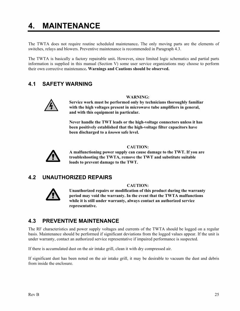
4.1 SAFETY WARNING
WARNING: Service work must be performed only by technicians thoroughly familiar
with the high voltages present in microwave tube amplifiers in general, and with this equipment in particular.
Never handle the TWT leads or the high-voltage connectors unless it has been positively established that the high-voltage filter capacitors have been discharged to a known safe level.
CAUTION:
A malfunctioning power supply can cause damage to the TWT. If you are troubleshooting the TWTA, remove the TWT and substitute suitable loads to prevent damage to the TWT.
4.2 UNAUTHORIZED REPAIRS CAUTION:
Unauthorized repairs or modification of this product during the warranty period may void the warranty. In the event that the TWTA malfunctions while it is still under warranty, always contact an authorized service representative.
4.3 PREVENTIVE MAINTENANCE The RF characteristics and power supply voltages and currents of the TWTA should be logged on a regular basis. Maintenance should be performed if significant deviations from the logged values appear. If the unit is under warranty, contact an authorized service representative if impaired performance is suspected.
If there is accumulated dust on the air intake grill, clean it with dry compressed air.
If significant dust has been noted on the air intake grill, it may be desirable to vacuum the dust and debris from inside the enclosure.
Rev B 25
Model 20T4G18 To open the enclosure:
1. Remove the amplifier from the cabinet or rack as follows:
NOTE: Due to the weight of the unit, the removal of the amplifier from the cabinet or rack is a two person operation.
Disconnect power, RF, and any other interface connectors. On the rear of the unit, remove any screws used to connect brackets to the amplifier. On the front of the unit, remove the four screws holding the front panel onto the cabinet. Carefully slide the amplifier out of the front of the cabinet.
2. Remove the 12 screws that secure the lower cover and the 12 screws that secure the upper cover. Remove the covers to gain access to the interior of the TWTA.
Vacuum dust and debris from inside the enclosure. Clean dust from the TWTA and its flying leads. Remove any dirt from around the three high voltage connectors. While the cover is off, check for loose wires, components or fasteners.
Reassemble in the reverse order.
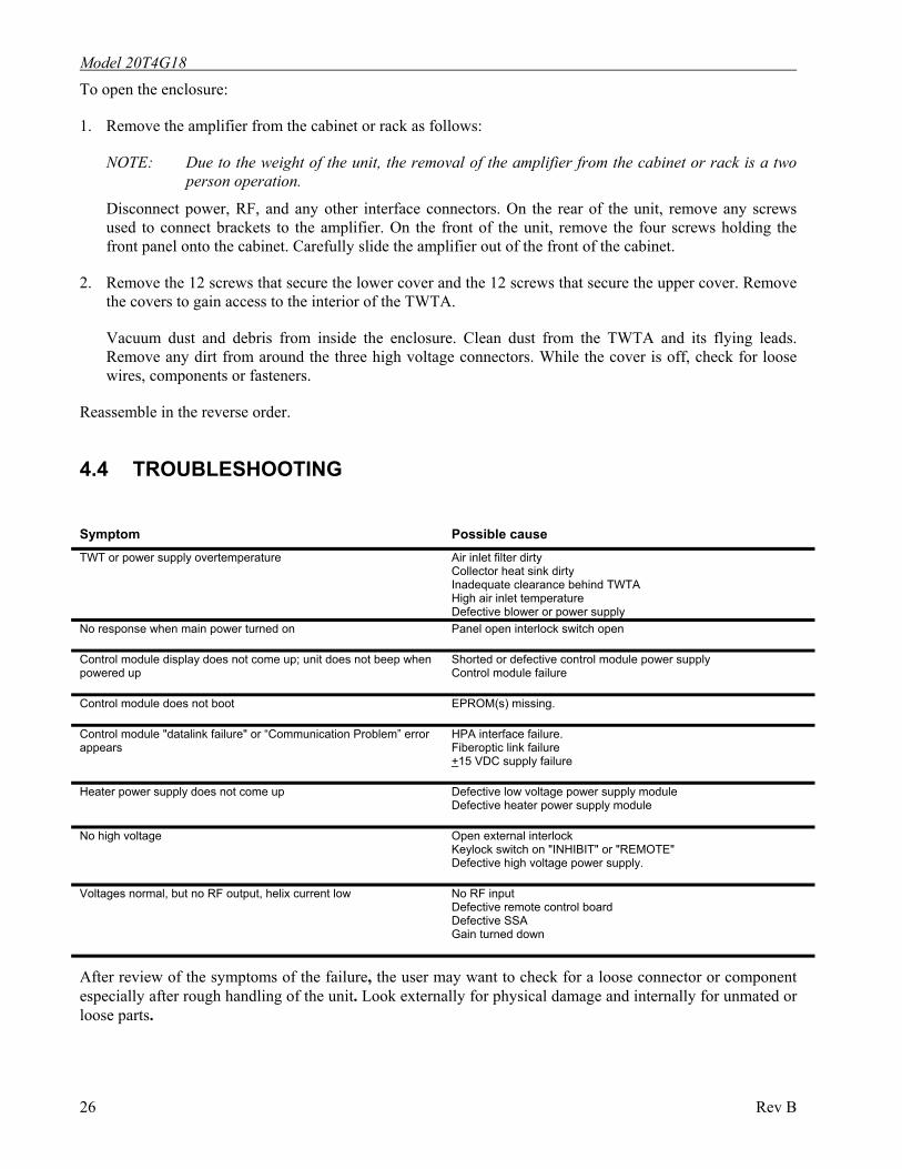
4.4 TROUBLESHOOTING
Symptom Possible cause TWT or power supply overtemperature Air inlet filter dirty
Collector heat sink dirty Inadequate clearance behind TWTA High air inlet temperature Defective blower or power supply
No response when main power turned on
Panel open interlock switch open
Control module display does not come up; unit does not beep when powered up
Shorted or defective control module power supply Control module failure
Control module does not boot EPROM(s) missing.
Control module "datalink failure" or “Communication Problem” error appears
HPA interface failure. Fiberoptic link failure +15 VDC supply failure
Heater power supply does not come up Defective low voltage power supply module Defective heater power supply module
No high voltage Open external interlock Keylock switch on "INHIBIT" or "REMOTE" Defective high voltage power supply.
Voltages normal, but no RF output, helix current low No RF input Defective remote control board Defective SSA Gain turned down
After review of the symptoms of the failure, the user may want to check for a loose connector or component especially after rough handling of the unit. Look externally for physical damage and internally for unmated or loose parts.
26 Rev B
Model 20T4G18
The service technician should become familiar with the internal mechanical construction to permit correct re-assembly. Limited troubleshooting may be conducted, with caution, based on the failure symptom and an understanding of the logic/schematic diagrams.
4.5 NON-REPAIRABLE MODULES The High Voltage Diode/Cap Assembly (A21455-100), the High Voltage Filter Assembly (A21454), and the Heater Supply (A10010-000) are encapsulated modules and are not repairable. Contact an authorized service representative if replacement modules are needed.
Rev B 27

Model 20T4G18
28 Rev B

5. TECHNICAL DOCUMENTATION
NOTE: The purpose of this technical documentation section is to provide a guide to the TWTA for technician-level servicing. It is intended for use by qualified technical personnel who must troubleshoot and repair the TWTA in the field. Such repairs are typically limited to replacement of modules or major components. For this reason, documentation pertaining to the highest levels of the system and to system control logic is included.
Rev B 29
Model 20T4G18
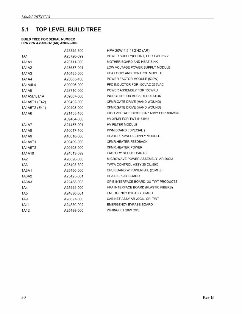
5.1 TOP LEVEL BUILD TREE BUILD TREE FOR SERIAL NUMBER HPA 20W 4.2-18GHZ (AR) A28825-300 A28825-300 HPA 20W 4.2-18GHZ (AR) 1A1 A23720-099 POWER SUPPLY(SHORT) FOR TWT 5172 1A1A1 A23711-000 MOTHER BOARD AND HEAT SINK 1A1A2 A23687-001 LOW VOLTAGE POWER SUPPLY MODULE 1A1A3 A16485-000 HPA LOGIC AND CONTROL MODULE 1A1A4 A23683-100 POWER FACTOR MODULE (500W) 1A1A4L4 A09006-000 PFC INDUCTOR FOR 100VAC-255VAC 1A1A5 A23710-000 POWER ASSEMBLY FOR 100WKU 1A1A5L1, L1A A09007-000 INDUCTOR FOR BUCK REGULATOR 1A1A5T1 (E42) A09402-000 XFMR,GATE DRIVE (HAND WOUND) 1A1A5T2 (E41) A09403-000 XFMR,GATE DRIVE (HAND WOUND) 1A1A6 A21455-100 HIGH VOLTAGE DIODE/CAP ASSY FOR 100WKU A09484-000 HV XFMR FOR TWT 5181KU 1A1A7 A21457-001 HV FILTER MODULE 1A1A8 A10017-100 PWM BOARD ( SPECIAL ) 1A1A9 A10010-000 HEATER POWER SUPPLY MODULE 1A1A9T1 A09409-000 XFMR,HEATER FEEDBACK 1A1A9T2 A09408-000 XFMR,HEATER POWER 1A1A10 A24513-099 FACTORY SELECT PARTS 1A2 A28826-000 MICROWAVE POWER ASSEMBLY, AR 20CIJ 1A3 A25403-302 TWTA CONTROL ASSY 20 CIJ/50X 1A3A1 A25450-000 CPU BOARD W/POWERFAIL (20MHZ) 1A3A2 A25425-001 HPA DISPLAY BOARD 1A3A3 A22488-003 GPIB INTERFACE BOARD, 3U TWT PRODUCTS 1A4 A25444-000 HPA INTERFACE BOARD (PLASTIC FIBERS) 1A5 A24830-001 EMERGENCY BYPASS BOARD 1A9 A28827-000 CABINET ASSY AR 20CIJ, CPI TWT 1A11 A24830-002 EMERGENCY BYPASS BOARD
1A12 A25498-000 WIRING KIT 20W C/I/J
30 Rev B

Model 20T4G18
5.2 SCHEMATICS 10-16485-000 HPA Logic and Control (A16485-000)
10-25444-000 HPA Interface (A22444-000)
10-24830 Emergency Bypass Board (A24830-001)
10-24830-002 Emergency Bypass Board (A24830-002)
10-28825-300 HPA 20T Series (A28825-300)
Rev B 31

Model 20T4G18
32 Rev B

Model 20T4G18
5.3 WIRING DIAGRAMS 20-23720-099 TWT Power Supply AR 20T Series (A23720-099)
Rev B 33

Model 20T4G18
34 Rev B
Model 20T4G18
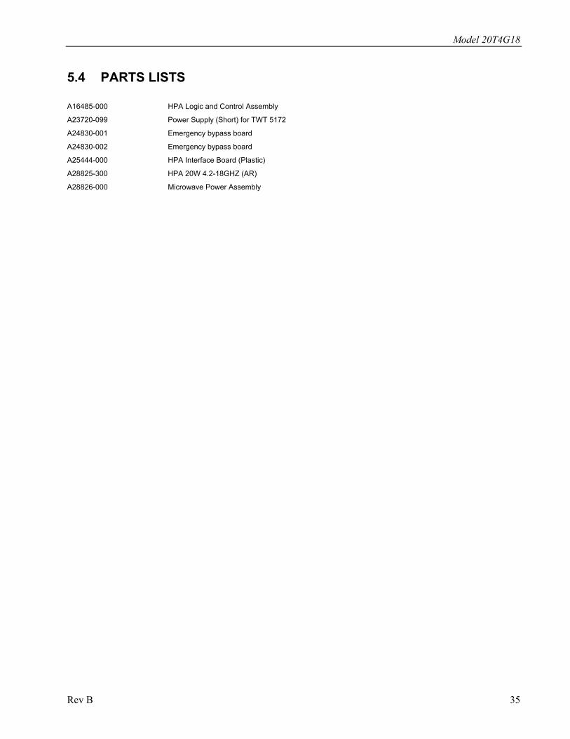
5.4 PARTS LISTS A16485-000 HPA Logic and Control Assembly
A23720-099 Power Supply (Short) for TWT 5172
A24830-001 Emergency bypass board
A24830-002 Emergency bypass board
A25444-000 HPA Interface Board (Plastic)
A28825-300 HPA 20W 4.2-18GHZ (AR)
A28826-000 Microwave Power Assembly
Rev B 35
Model 20T4G18
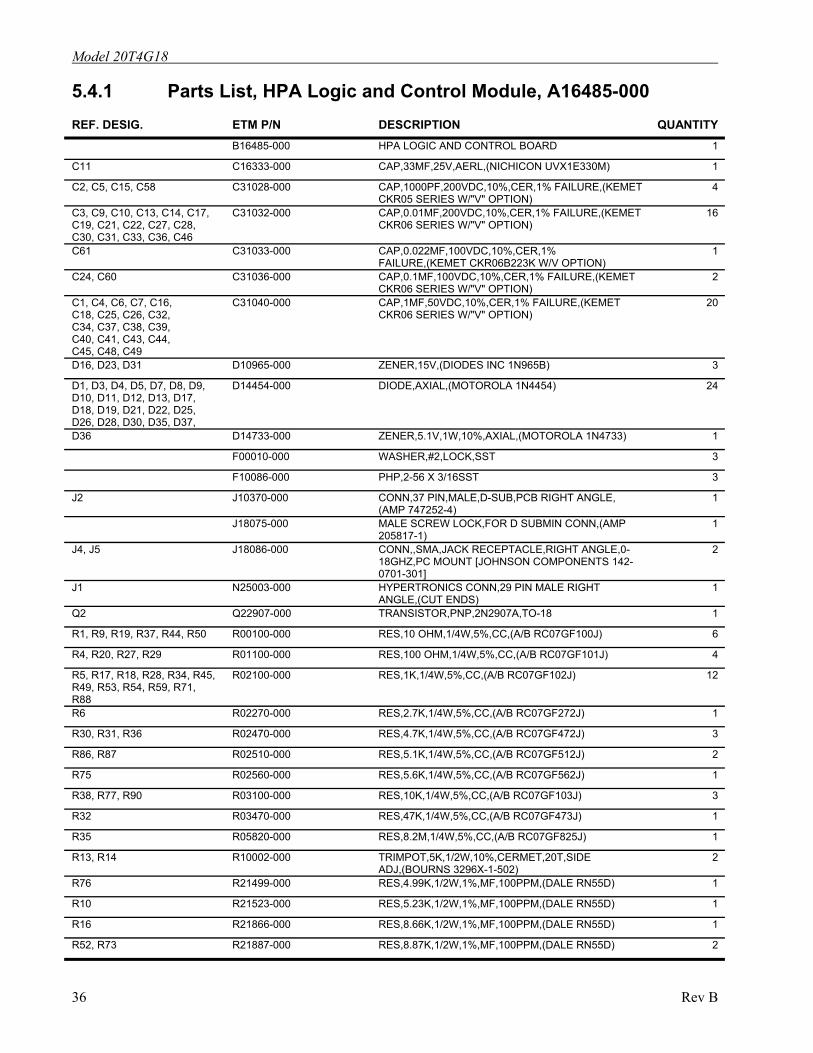
5.4.1 Parts List, HPA Logic and Control Module, A16485-000 REF. DESIG. ETM P/N DESCRIPTION QUANTITY
B16485-000 HPA LOGIC AND CONTROL BOARD 1
C11 C16333-000 CAP,33MF,25V,AERL,(NICHICON UVX1E330M) 1
C2, C5, C15, C58 C31028-000 CAP,1000PF,200VDC,10%,CER,1% FAILURE,(KEMET CKR05 SERIES W/"V" OPTION)
4
C3, C9, C10, C13, C14, C17, C19, C21, C22, C27, C28, C30, C31, C33, C36, C46
C31032-000 CAP,0.01MF,200VDC,10%,CER,1% FAILURE,(KEMET CKR06 SERIES W/"V" OPTION)
16
C61 C31033-000 CAP,0.022MF,100VDC,10%,CER,1% FAILURE,(KEMET CKR06B223K W/V OPTION)
1
C24, C60 C31036-000 CAP,0.1MF,100VDC,10%,CER,1% FAILURE,(KEMET CKR06 SERIES W/"V" OPTION)
2
C1, C4, C6, C7, C16, C18, C25, C26, C32, C34, C37, C38, C39, C40, C41, C43, C44, C45, C48, C49
C31040-000 CAP,1MF,50VDC,10%,CER,1% FAILURE,(KEMET CKR06 SERIES W/"V" OPTION)
20
D16, D23, D31 D10965-000 ZENER,15V,(DIODES INC 1N965B) 3
D1, D3, D4, D5, D7, D8, D9, D10, D11, D12, D13, D17, D18, D19, D21, D22, D25, D26, D28, D30, D35, D37,
D14454-000 DIODE,AXIAL,(MOTOROLA 1N4454) 24
D36 D14733-000 ZENER,5.1V,1W,10%,AXIAL,(MOTOROLA 1N4733) 1
F00010-000 WASHER,#2,LOCK,SST 3
F10086-000 PHP,2-56 X 3/16SST 3
J2 J10370-000 CONN,37 PIN,MALE,D-SUB,PCB RIGHT ANGLE, (AMP 747252-4)
1
J18075-000 MALE SCREW LOCK,FOR D SUBMIN CONN,(AMP 205817-1)
1
J4, J5 J18086-000 CONN,,SMA,JACK RECEPTACLE,RIGHT ANGLE,0-18GHZ,PC MOUNT [JOHNSON COMPONENTS 142-0701-301]
2
J1 N25003-000 HYPERTRONICS CONN,29 PIN MALE RIGHT ANGLE,(CUT ENDS)
1
Q2 Q22907-000 TRANSISTOR,PNP,2N2907A,TO-18 1
R1, R9, R19, R37, R44, R50 R00100-000 RES,10 OHM,1/4W,5%,CC,(A/B RC07GF100J) 6
R4, R20, R27, R29 R01100-000 RES,100 OHM,1/4W,5%,CC,(A/B RC07GF101J) 4
R5, R17, R18, R28, R34, R45, R49, R53, R54, R59, R71, R88
R02100-000 RES,1K,1/4W,5%,CC,(A/B RC07GF102J) 12
R6 R02270-000 RES,2.7K,1/4W,5%,CC,(A/B RC07GF272J) 1
R30, R31, R36 R02470-000 RES,4.7K,1/4W,5%,CC,(A/B RC07GF472J) 3
R86, R87 R02510-000 RES,5.1K,1/4W,5%,CC,(A/B RC07GF512J) 2
R75 R02560-000 RES,5.6K,1/4W,5%,CC,(A/B RC07GF562J) 1
R38, R77, R90 R03100-000 RES,10K,1/4W,5%,CC,(A/B RC07GF103J) 3
R32 R03470-000 RES,47K,1/4W,5%,CC,(A/B RC07GF473J) 1
R35 R05820-000 RES,8.2M,1/4W,5%,CC,(A/B RC07GF825J) 1
R13, R14 R10002-000 TRIMPOT,5K,1/2W,10%,CERMET,20T,SIDE ADJ,(BOURNS 3296X-1-502)
2
R76 R21499-000 RES,4.99K,1/2W,1%,MF,100PPM,(DALE RN55D) 1
R10 R21523-000 RES,5.23K,1/2W,1%,MF,100PPM,(DALE RN55D) 1
R16 R21866-000 RES,8.66K,1/2W,1%,MF,100PPM,(DALE RN55D) 1
R52, R73 R21887-000 RES,8.87K,1/2W,1%,MF,100PPM,(DALE RN55D) 2
36 Rev B

Model 20T4G18
REF. DESIG. ETM P/N DESCRIPTION QUANTITYR67 R21953-000 RES,9.53K,1/2W,1%,MF,100PPM,(DALE RN55D) 1
R47, R48 R22200-000 RES,20K,1/2W,1%,MF,100PPM,(DALE RN55D) 2
R79, R80 R22470-000 RES,47K,1/2W,1%,MF,100PPM,(DALE RN55D) 2
R42, R60, R61, R89 R23100-000 RES,100K,1/2W,1%,MF,100PPM,(DALE RN55D) 4
R33, R55 R23698-000 RES,698K,1/2W,1%,MF,100PPM,(DALE RN55D) 2
R41 R23750-000 RES,750K,1/2W,1%,MF,100PPM,(DALE RN55D) 1
R21 R23845-000 RES,845K,1/2W,1%,MF,100PPM,(DALE RN55D) 1
R66 R23953-000 RES,953K,1/2W,1%,MF,100PPM,(DALE RN55D) 1
R12, R15 R32020-000 TRIMPOT,10K,1/2W,10%,CERMET,20T,SIDE ADJ,(BECKMAN 67X)
2
U4, U5, U6 U02390-000 IC,QUAD COMPARATOR,(NAT LM139J) 3
U7 U03240-000 IC,LOW POWER OP AMP,(NAT LM324) 1
U9 U10070-000 REFERENCE,PRECISION 10V [LINEAR TECH LT1031DCH]
1
U8 U17805-000 IC,5V REGULATOR,TO-220,(NAT LM340T-5.0) 1
U1, U2, U3 U20148-000 IC,HEX INVERTER,SCHMIDTT TRIGGER,(74HC14) (SSD)
3
RP8 U30106-000 IC,10K,RES NETWORK,6 PIN,SIP (DALE MSP06A-01-103G)
1
RP1-2, RP5-7, RP9 U30410-000 IC,10K,2%,0.40A,10 PIN,ISOLATED RESISTORS (DALE MSP10C-03-103G OR BOURNS 4610H-102-103)
6
RP4 U31020-000 IC,1K RES NETWORK,SIP,(BECKMAN L061C102G) 1
W3-W8 W12200-000 WIRE, 22 AWG, BLU, 600V, TEFLON, (BELDEN 83006)
6
Rev B 37
Model 20T4G18
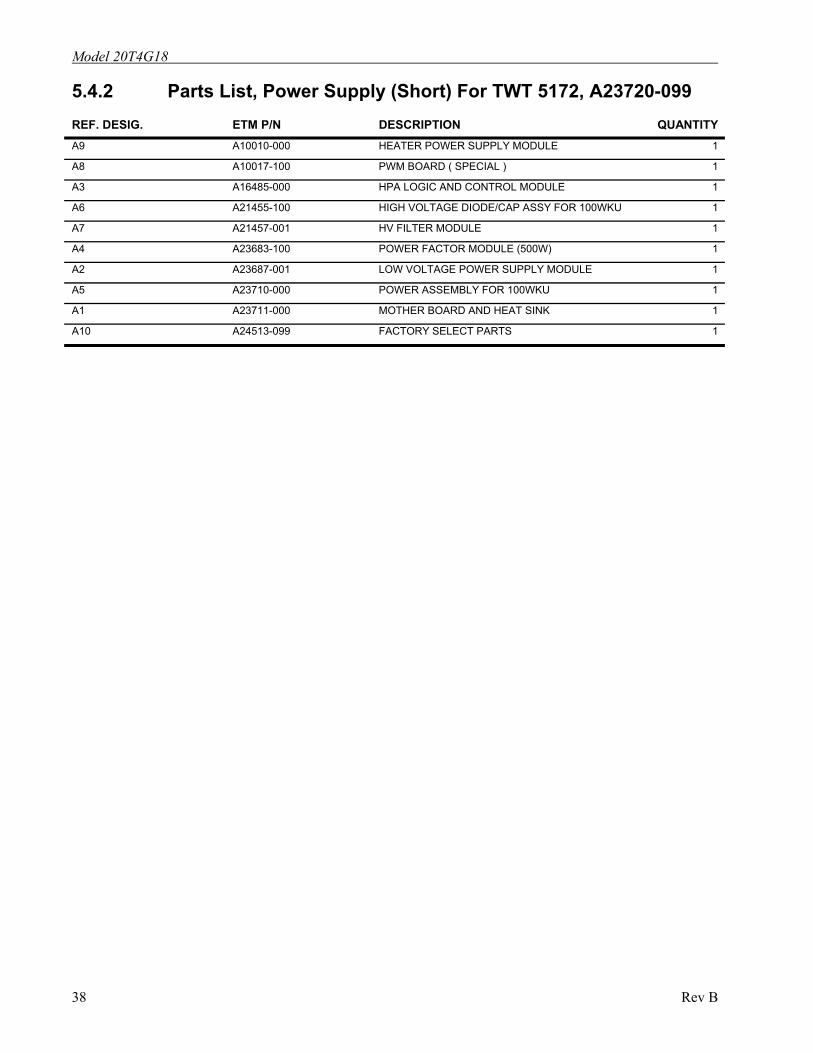
5.4.2 Parts List, Power Supply (Short) For TWT 5172, A23720-099 REF. DESIG. ETM P/N DESCRIPTION QUANTITY A9 A10010-000 HEATER POWER SUPPLY MODULE 1
A8 A10017-100 PWM BOARD ( SPECIAL ) 1
A3 A16485-000 HPA LOGIC AND CONTROL MODULE 1
A6 A21455-100 HIGH VOLTAGE DIODE/CAP ASSY FOR 100WKU 1
A7 A21457-001 HV FILTER MODULE 1
A4 A23683-100 POWER FACTOR MODULE (500W) 1
A2 A23687-001 LOW VOLTAGE POWER SUPPLY MODULE 1
A5 A23710-000 POWER ASSEMBLY FOR 100WKU 1
A1 A23711-000 MOTHER BOARD AND HEAT SINK 1
A10 A24513-099 FACTORY SELECT PARTS 1
38 Rev B
Model 20T4G18
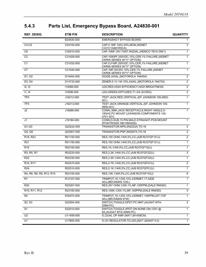
5.4.3 Parts List, Emergency Bypass Board, A24830-001 REF. DESIG. ETM P/N DESCRIPTION QUANTITY B24830-000 EMERGENCY BYPASS BOARD 1
C3-C5 C04105-000 CAP,0.1MF,100V,20%,MON,(KEMET C331C104M1R5CA)
3
C6 C30010-000 CAP,10MF,35V,TANT,RADIAL,(NEMCO TB10-35K1) 1
C2 C31028-000 CAP,1000PF,200VDC,10%,CER,1% FAILURE,(KEMET CKR05 SERIES W/"V" OPTION)
1
C1 C31032-000 CAP,0.01MF,200VDC,10%,CER,1% FAILURE,(KEMET CKR06 SERIES W/"V" OPTION)
1
C7 C31040-000 CAP,1MF,50VDC,10%,CER,1% FAILURE,(KEMET CKR06 SERIES W/"V" OPTION)
1
D1, D2 D14454-000 DIODE,AXIAL,(MOTOROLA 1N4454) 2
D3, D4 D14733-000 ZENER,5.1V,1W,10%,AXIAL,(MOTOROLA 1N4733) 2
I2, I3 I10066-000 LED,RED,HIGH EFFICIENCY,HIGH BRIGHTNESS 2
I1, I4 I10096-000 LED,GREEN,DIFFUSED,T1-3/4 (XC55G) 2
TP2 J16212-000 TEST JACK,RED,VERTICAL,(EF JOHNSON 105-0852-001)
1
TP3 J16213-000 TEST JACK,ORANGE,VERTICAL,(EF JOHNSON 105-0856-001)
1
J2 J18086-000 CONN,,SMA,JACK RECEPTACLE,RIGHT ANGLE,0-18GHZ,PC MOUNT [JOHNSON COMPONENTS 142-0701-301]
1
J1 J18180-000 CONN,D-SUB,15 PIN,MALE,STRAIGHT,PCB MOUNT (POSITRONIC MD15M3000)
1
Q1-Q3 Q22222-000 TRANSISTOR,NPN,2N2222A,TO-18 3
Q4, Q5 Q22907-000 TRANSISTOR,PNP,2N2907A,TO-18 2
R18, R23 R01100-000 RES,100 OHM,1/4W,5%,CC,(A/B RC07GF101J) 2
R21 R01150-000 RES,150 OHM,1/4W,5%,CC,(A/B RC07GF151J) 1
R19 R02100-000 RES,1K,1/4W,5%,CC,(A/B RC07GF102J) 1
R3, R5, R7 R02220-000 RES,2.2K,1/4W,5%,CC,(A/B RC07GF222J) 3
R22 R02330-000 RES,3.3K,1/4W,5%,CC,(A/B RC07GF332J) 1
R16, R17 R02470-000 RES,4.7K,1/4W,5%,CC,(A/B RC07GF472J) 2
R24 R02510-000 RES,5.1K,1/4W,5%,CC,(A/B RC07GF512J) 1
R4, R6, R8, R9, R13, R15 R03100-000 RES,10K,1/4W,5%,CC,(A/B RC07GF103J) 6
R1 R12107-000 TRIMPOT,1K,1/2W,10%,CERMET,1T,SIDE ADJ,(BECKMAN 72XL)
1
R20 R20267-000 RES,267 OHM,1/2W,1%,MF,100PPM,(DALE RN55D) 1
R10, R11, R12 R23100-000 RES,100K,1/2W,1%,MF,100PPM,(DALE RN55D) 3
R2 R30074-000 TRIMPOT,1K,1/2W,10%,CERMET,100PPM,20T,TOP ADJ,(BECKMAN 67W)
1
S2, S3 S22004-000 SWITCH,TOGGLE,DPDT,PC MNT,(AUGAT MTA-206N-PC)
2
S1 S22010-000 SWITCH,TOGGLE,4PDT,ON-NONE-ON,125V @ 6A,(AUGAT MTA-406N-PC)
1
U2 U11458-000 IC,DUAL OP AMP,(NAT LM1458CN) 1
U1 U17805-000 IC,5V REGULATOR,TO-220,(NAT LM340T-5.0) 1
Rev B 39
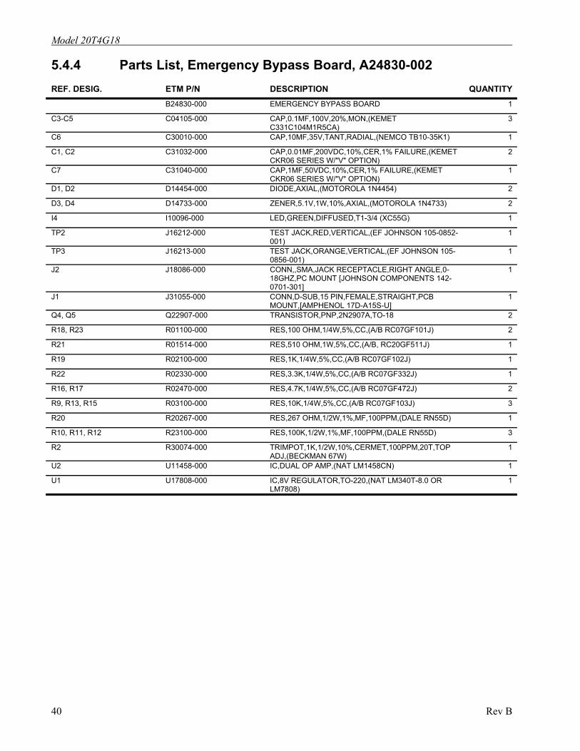
Model 20T4G18
5.4.4 Parts List, Emergency Bypass Board, A24830-002 REF. DESIG. ETM P/N DESCRIPTION QUANTITY B24830-000 EMERGENCY BYPASS BOARD 1
C3-C5 C04105-000 CAP,0.1MF,100V,20%,MON,(KEMET C331C104M1R5CA)
3
C6 C30010-000 CAP,10MF,35V,TANT,RADIAL,(NEMCO TB10-35K1) 1
C1, C2 C31032-000 CAP,0.01MF,200VDC,10%,CER,1% FAILURE,(KEMET CKR06 SERIES W/"V" OPTION)
2
C7 C31040-000 CAP,1MF,50VDC,10%,CER,1% FAILURE,(KEMET CKR06 SERIES W/"V" OPTION)
1
D1, D2 D14454-000 DIODE,AXIAL,(MOTOROLA 1N4454) 2
D3, D4 D14733-000 ZENER,5.1V,1W,10%,AXIAL,(MOTOROLA 1N4733) 2
I4 I10096-000 LED,GREEN,DIFFUSED,T1-3/4 (XC55G) 1
TP2 J16212-000 TEST JACK,RED,VERTICAL,(EF JOHNSON 105-0852-001)
1
TP3 J16213-000 TEST JACK,ORANGE,VERTICAL,(EF JOHNSON 105-0856-001)
1
J2 J18086-000 CONN,,SMA,JACK RECEPTACLE,RIGHT ANGLE,0-18GHZ,PC MOUNT [JOHNSON COMPONENTS 142-0701-301]
1
J1 J31055-000 CONN,D-SUB,15 PIN,FEMALE,STRAIGHT,PCB MOUNT,[AMPHENOL 17D-A15S-U]
1
Q4, Q5 Q22907-000 TRANSISTOR,PNP,2N2907A,TO-18 2
R18, R23 R01100-000 RES,100 OHM,1/4W,5%,CC,(A/B RC07GF101J) 2
R21 R01514-000 RES,510 OHM,1W,5%,CC,(A/B, RC20GF511J) 1
R19 R02100-000 RES,1K,1/4W,5%,CC,(A/B RC07GF102J) 1
R22 R02330-000 RES,3.3K,1/4W,5%,CC,(A/B RC07GF332J) 1
R16, R17 R02470-000 RES,4.7K,1/4W,5%,CC,(A/B RC07GF472J) 2
R9, R13, R15 R03100-000 RES,10K,1/4W,5%,CC,(A/B RC07GF103J) 3
R20 R20267-000 RES,267 OHM,1/2W,1%,MF,100PPM,(DALE RN55D) 1
R10, R11, R12 R23100-000 RES,100K,1/2W,1%,MF,100PPM,(DALE RN55D) 3
R2 R30074-000 TRIMPOT,1K,1/2W,10%,CERMET,100PPM,20T,TOP ADJ,(BECKMAN 67W)
1
U2 U11458-000 IC,DUAL OP AMP,(NAT LM1458CN) 1
U1 U17808-000 IC,8V REGULATOR,TO-220,(NAT LM340T-8.0 OR LM7808)
1
40 Rev B
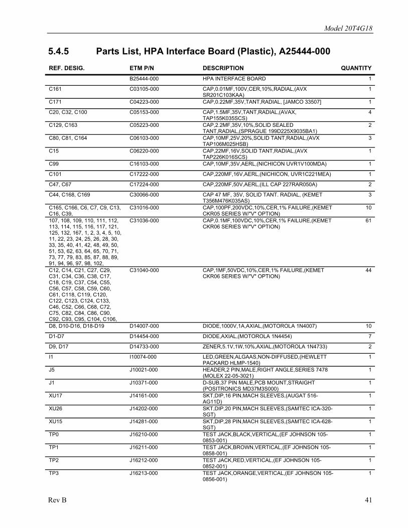
Model 20T4G18
5.4.5 Parts List, HPA Interface Board (Plastic), A25444-000 REF. DESIG. ETM P/N DESCRIPTION QUANTITY
B25444-000 HPA INTERFACE BOARD 1
C161 C03105-000 CAP,0.01MF,100V,CER,10%,RADIAL,(AVX SR201C103KAA)
1
C171 C04223-000 CAP,0.22MF,35V,TANT,RADIAL, [JAMCO 33507] 1
C20, C32, C100 C05153-000 CAP,1.5MF,35V,TANT,RADIAL,(AVAX, TAP155K035SCS)
4
C129, C163 C05223-000 CAP,2.2MF,35V,10%,SOLID SEALED TANT,RADIAL,(SPRAGUE 199D225X9035BA1)
2
C80, C81, C164 C06103-000 CAP,10MF,25V,20%,SOLID TANT,RADIAL,(AVX TAP106M025HSB)
3
C15 C06220-000 CAP,22MF,16V,SOLID TANT,RADIAL,(AVX TAP226K016SCS)
1
C99 C16103-000 CAP,10MF,35V,AERL,(NICHICON UVR1V100MDA) 1
C101 C17222-000 CAP,220MF,16V,AERL,(NICHICON, UVR1C221MEA) 1
C47, C67 C17224-000 CAP,220MF,50V,AERL,(ILL CAP 227RAR050A) 2
C44, C168, C169 C30066-000 CAP 47 MF, 35V, SOLID TANT. RADIAL, (KEMET T356M476K035AS)
3
C165, C166, C6, C7, C9, C13, C16, C39,
C31016-000 CAP,100PF,200VDC,10%,CER,1% FAILURE,(KEMET CKR05 SERIES W/"V" OPTION)
10
107, 108, 109, 110, 111, 112, 113, 114, 115, 116, 117, 121, 125, 132, 167, 1, 2, 3, 4, 5, 10, 11, 22, 23, 24, 25, 26, 28, 30, 33, 35, 40, 41, 42, 48, 49, 50, 51, 53, 62, 63, 64, 65, 70, 71, 73, 77, 79, 83, 85, 87, 88, 89, 91, 94, 96, 97, 98, 102,
C31036-000 CAP,0.1MF,100VDC,10%,CER,1% FAILURE,(KEMET CKR06 SERIES W/"V" OPTION)
61
C12, C14, C21, C27, C29, C31, C34, C36, C38, C17, C18, C19, C37, C54, C55, C56, C57, C58, C59, C60, C61, C118, C119, C120, C122, C123, C124, C133, C46, C52, C66, C68, C72, C75, C82, C84, C86, C90, C92, C93, C95, C104, C106,
C31040-000 CAP,1MF,50VDC,10%,CER,1% FAILURE,(KEMET CKR06 SERIES W/"V" OPTION)
44
D8, D10-D16, D18-D19 D14007-000 DIODE,1000V,1A,AXIAL,(MOTOROLA 1N4007) 10
D1-D7 D14454-000 DIODE,AXIAL,(MOTOROLA 1N4454) 7
D9, D17 D14733-000 ZENER,5.1V,1W,10%,AXIAL,(MOTOROLA 1N4733) 2
I1 I10074-000 LED,GREEN,ALGAAS,NON-DIFFUSED,(HEWLETT PACKARD HLMP-1540)
1
J5 J10021-000 HEADER,2 PIN,MALE,RIGHT ANGLE,SERIES 7478 (MOLEX 22-05-3021)
1
J1 J10371-000 D-SUB,37 PIN MALE,PCB MOUNT,STRAIGHT (POSITRONICS MD37M3S000)
1
XU17 J14161-000 SKT,DIP,16 PIN,MACH SLEEVES,(AUGAT 516-AG11D)
1
XU26 J14202-000 SKT,DIP,20 PIN,MACH SLEEVES,(SAMTEC ICA-320-SGT)
1
XU15 J14281-000 SKT,DIP,28 PIN,MACH SLEEVES,(SAMTEC ICA-628-SGT)
1
TP0 J16210-000 TEST JACK,BLACK,VERTICAL,(EF JOHNSON 105-0853-001)
1
TP1 J16211-000 TEST JACK,BROWN,VERTICAL,(EF JOHNSON 105-0858-001)
1
TP2 J16212-000 TEST JACK,RED,VERTICAL,(EF JOHNSON 105-0852-001)
1
TP3 J16213-000 TEST JACK,ORANGE,VERTICAL,(EF JOHNSON 105-0856-001)
1
Rev B 41
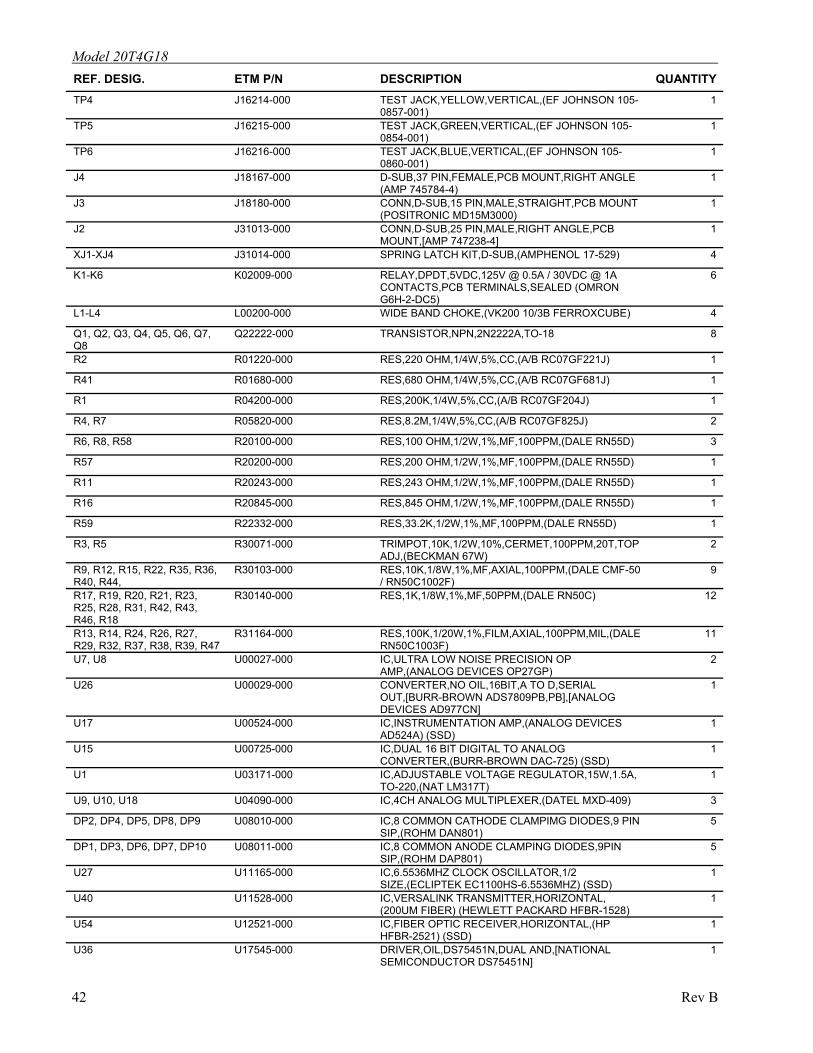
Model 20T4G18 REF. DESIG. ETM P/N DESCRIPTION QUANTITYTP4 J16214-000 TEST JACK,YELLOW,VERTICAL,(EF JOHNSON 105-
0857-001) 1
TP5 J16215-000 TEST JACK,GREEN,VERTICAL,(EF JOHNSON 105-0854-001)
1
TP6 J16216-000 TEST JACK,BLUE,VERTICAL,(EF JOHNSON 105-0860-001)
1
J4 J18167-000 D-SUB,37 PIN,FEMALE,PCB MOUNT,RIGHT ANGLE (AMP 745784-4)
1
J3 J18180-000 CONN,D-SUB,15 PIN,MALE,STRAIGHT,PCB MOUNT (POSITRONIC MD15M3000)
1
J2 J31013-000 CONN,D-SUB,25 PIN,MALE,RIGHT ANGLE,PCB MOUNT,[AMP 747238-4]
1
XJ1-XJ4 J31014-000 SPRING LATCH KIT,D-SUB,(AMPHENOL 17-529) 4
K1-K6 K02009-000 RELAY,DPDT,5VDC,125V @ 0.5A / 30VDC @ 1A CONTACTS,PCB TERMINALS,SEALED (OMRON G6H-2-DC5)
6
L1-L4 L00200-000 WIDE BAND CHOKE,(VK200 10/3B FERROXCUBE) 4
Q1, Q2, Q3, Q4, Q5, Q6, Q7, Q8
Q22222-000 TRANSISTOR,NPN,2N2222A,TO-18 8
R2 R01220-000 RES,220 OHM,1/4W,5%,CC,(A/B RC07GF221J) 1
R41 R01680-000 RES,680 OHM,1/4W,5%,CC,(A/B RC07GF681J) 1
R1 R04200-000 RES,200K,1/4W,5%,CC,(A/B RC07GF204J) 1
R4, R7 R05820-000 RES,8.2M,1/4W,5%,CC,(A/B RC07GF825J) 2
R6, R8, R58 R20100-000 RES,100 OHM,1/2W,1%,MF,100PPM,(DALE RN55D) 3
R57 R20200-000 RES,200 OHM,1/2W,1%,MF,100PPM,(DALE RN55D) 1
R11 R20243-000 RES,243 OHM,1/2W,1%,MF,100PPM,(DALE RN55D) 1
R16 R20845-000 1
R59 R22332-000 RES,33.2K,1/2W,1%,MF,100PPM,(DALE RN55D) 1
R3, R5 R30071-000 TRIMPOT,10K,1/2W,10%,CERMET,100PPM,20T,TOP ADJ,(BECKMAN 67W)
2
R9, R12, R15, R22, R35, R36, R40, R44,
R30103-000 RES,10K,1/8W,1%,MF,AXIAL,100PPM,(DALE CMF-50 / RN50C1002F)
9
R17, R19, R20, R21, R23, R25, R28, R31, R42, R43, R46, R18
R30140-000 RES,1K,1/8W,1%,MF,50PPM,(DALE RN50C) 12
R13, R14, R24, R26, R27, R29, R32, R37, R38, R39, R47
R31164-000 RES,100K,1/20W,1%,FILM,AXIAL,100PPM,MIL,(DALE RN50C1003F)
11
U7, U8 U00027-000 IC,ULTRA LOW NOISE PRECISION OP AMP,(ANALOG DEVICES OP27GP)
2
U26 U00029-000 CONVERTER,NO OIL,16BIT,A TO D,SERIAL OUT,[BURR-BROWN ADS7809PB,PB],[ANALOG DEVICES AD977CN]
1
U17 U00524-000 IC,INSTRUMENTATION AMP,(ANALOG DEVICES AD524A) (SSD)
1
U15 U00725-000 IC,DUAL 16 BIT DIGITAL TO ANALOG CONVERTER,(BURR-BROWN DAC-725) (SSD)
1
U1 U03171-000 IC,ADJUSTABLE VOLTAGE REGULATOR,15W,1.5A, TO-220,(NAT LM317T)
1
U9, U10, U18 U04090-000 IC,4CH ANALOG MULTIPLEXER,(DATEL MXD-409) 3
DP2, DP4, DP5, DP8, DP9 U08010-000 IC,8 COMMON CATHODE CLAMPIMG DIODES,9 PIN SIP,(ROHM DAN801)
5
DP1, DP3, DP6, DP7, DP10 U08011-000 IC,8 COMMON ANODE CLAMPING DIODES,9PIN SIP,(ROHM DAP801)
5
U27 U11165-000 IC,6.5536MHZ CLOCK OSCILLATOR,1/2 SIZE,(ECLIPTEK EC1100HS-6.5536MHZ) (SSD)
1
U40 U11528-000 IC,VERSALINK TRANSMITTER,HORIZONTAL, (200UM FIBER) (HEWLETT PACKARD HFBR-1528)
1
U54 U12521-000 IC,FIBER OPTIC RECEIVER,HORIZONTAL,(HP HFBR-2521) (SSD)
1
U36 U17545-000 DRIVER,OIL,DS75451N,DUAL AND,[NATIONAL SEMICONDUCTOR DS75451N]
1
RES,845 OHM,1/2W,1%,MF,100PPM,(DALE RN55D)
42 Rev B
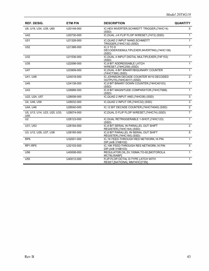
Model 20T4G18
REF. DESIG. ETM P/N DESCRIPTION QUANTITYU6, U19, U34, U39, U60 U20148-000 IC,HEX INVERTER,SCHMIDTT TRIGGER,(74HC14)
(SSD) 5
U42 U20730-000 IC,DUAL J-K FLIP FLOP W/RESET,(7473) (SSD) 1
U51 U21328-000 IC,QUAD 2 INPUT NAND,SCHMIDTT TRIGGER,(74HC132) (SSD)
1
U52 U21388-000 IC,3 TO 8 DECODER/DEMULTIPLEXER,INVERTING,(74HC138) (SSD)
1
U32 U21536-000 IC,DUAL 4 INPUT DIGTAL MULTIPLEXER,(74F153) (SSD)
1
U35 U22598-000 IC,8 BIT ADDRESSABLE LATCH W/RESET,(74HC259) (SSD)
1
U47 U23909-000 IC,DUAL 4 BIT BINARY/BIQUINARY COUNTER (74HCT390) (SSD)
1
U41, U48 U24018-000 IC,JOHNSON DECADE COUNTER W/10 DECODED OUTPUTS,(74HC4017) (SSD)
2
U45 U24138-000 IC,8 BIT BINARY DOWN COUNTER,(74HC40103) (SSD)
1
U43 U26889-000 IC,8 BIT MAGNITUDE COMPARATOR,(74HCT688) (SSD)
1
U22, U24, U57 U28008-000 IC,QUAD 2 INPUT AND,(74HC08) (SSD) 3
U4, U49, U58 U28032-000 IC,QUAD 2 INPUT OR,(74HC32) (SSD) 3
U44, U46 U28040-000 IC,12 BIT DECADE COUNTER,(74HCT4040) (SSD) 2
U5, U13, U14, U23, U25, U33, U50
U28074-000 IC,DUAL D FLIP FLOP W/RESET,(74HC74) (SSD) 7
U2 U28123-000 IC,DUAL RETRIGGERABLE 1-SHOT,(74HC123) (SSD)
1
U31, U53 U28164-000 IC,8 BIT SERIAL IN PARALLEL OUT SHIFT REGISTER,(74HC164) (SSD)
2
U3, U12, U28, U37, U38 U28165-000 IC,8 BIT PARALLEL IN SERIAL OUT SHIFT REGISTER,(74HC165) (SSD)
5
RP6 U32001-000 IC,1K FEED-THROUGH RES NETWORK,16 PIN DIP,(A/B 316B102)
1
RP1-RP5 U32103-000 IC,10K FEED-THROUGH RES NETWORK,16 PIN DIP,(A/B 316B103)
5
U56 U40008-000 REGULATOR,OIL,5V,100MA,TO-92,[MOTOROLA MC78L05ABP]
1
U55 U40012-000 FLIP-FLOP,OCTAL D-TYPE LATCH WITH RESET,[NATIONAL MM74HC273N]
1
Rev B 43
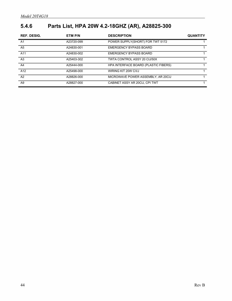
Model 20T4G18
5.4.6 Parts List, HPA 20W 4.2-18GHZ (AR), A28825-300 REF. DESIG. ETM P/N DESCRIPTION QUANTITY A1 A23720-099 POWER SUPPLY(SHORT) FOR TWT 5172 1
A5 A24830-001 EMERGENCY BYPASS BOARD 1
A11 A24830-002 EMERGENCY BYPASS BOARD 1
A3 A25403-302 TWTA CONTROL ASSY 20 CIJ/50X 1
A4 A25444-000 HPA INTERFACE BOARD (PLASTIC FIBERS) 1
A12 A25498-000 WIRING KIT 20W C/I/J 1
A2 A28826-000 MICROWAVE POWER ASSEMBLY, AR 20CIJ 1
A9 A28827-000 CABINET ASSY AR 20CIJ, CPI TWT 1
44 Rev B
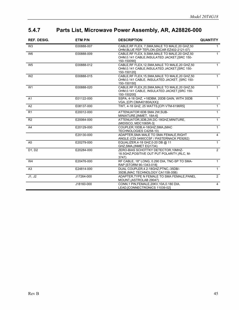
Model 20T4G18
5.4.7 Parts List, Microwave Power Assembly, AR, A28826-000 REF. DESIG. ETM P/N DESCRIPTION QUANTITY W3 E00888-007 CABLE,RF FLEX, 7,SMA,MALE TO MALE,20 GHZ,50
OHM,BLUE FEP TEFLON (DICAR EZ402-2121-07) 1
W6 E00888-009 CABLE,RF FLEX, 9,SMA,MALE TO MALE,20 GHZ,50 OHM,0.141 CABLE,INSULATED JACKET,[SRC 150-150-150090]
1
W5 E00888-012 CABLE,RF FLEX,12,SMA,MALE TO MALE,20 GHZ,50 OHM,0.141 CABLE,INSULATED JACKET,[SRC 150-150-150120]
1
W2 E00888-015 CABLE,RF FLEX,15,SMA,MALE TO MALE,20 GHZ,50 OHM,0.141 CABLE, INSULATED JACKET, [SRC 150-150-150150]
1
W1 E00888-020 CABLE,RF FLEX,20,SMA,MALE TO MALE,20 GHZ,50 OHM,0.141 CABLE, INSULATED JACKET,[SRC 150-150-150200]
1
A1 E01122-000 SSPA, 4-18 GHZ, +18DBM, 20DB GAIN, WITH 35DB VGA, [CPI CMA40180A(XX)]
1
A2 E08137-000 TWT, 4-18 GHZ, 25 WATTS,[CPI VTM-6196R5] 1
R1 E20012-000 ATTENUATOR 6DB SMA 2W,SUB-MINIATURE,[INMET, 18A-6]
1
R2 E20064-000 ATTENUATOR,3DB,2W,DC-18GHZ,MINITURE, (MIDISCO, MDC1065R-3]
1
A4 E20129-000 COUPLER,10DB,4-18GHZ,SMA,(MAC TECHNOLOGIES C4258-10)
1
E20130-000 ADAPTER,SMA MALE TO SMA FEMALE,RIGHT ANGLE (CDI 5490CCSF / PASTERNACK PE9262)
4
A5 E20279-000 EQUALIZER,4-18 GHZ,0-20 DB @ 11 GHZ,SMA,(INMET EQ1734)
1
D1, D2 E20284-000 ZERO-BIAS SCHOTTKY DETECTOR,10MHZ-18.5GHZ,POSITIVE OUT PUT POLARITY,(RLC, M-3747)
2
W4 E20476-000 RF CABLE, 18" LONG, 0.290 DIA, TNC-SP TO SMA-RAP [STORM 90-1343-018]
1
A3 E24814-000 DUAL COUPLER,4.2-18GHZ,PTNC,-35DB/-35DB,(MAC TECHNOLOGY CA1158-35B)
1
J1, J2 J17264-000 ADAPTER,TYPE N FEMALE TO SMA FEMALE,PANEL MOUNT,(ASTROLAB 29047)
2
J18160-000 CONN,1 PIN,FEMALE,20KV,10A,0.180 DIA. LEAD,[CONNECTRONICS 11039-02]
4
Rev B 45

Model 20T4G18
5.5 RECOMMENDED SPARE PARTS A16491-000 Auxiliary power supply module (low voltage power supply).
A21455-100 High voltage diode/cap assembly
A21454-000 High voltage filter assembly
A10010-000 Heater power supply module
Y10057-000 Spinnaker DC blower (Comair Rotron model SPD24B1, part no. 032183)
46 Rev B
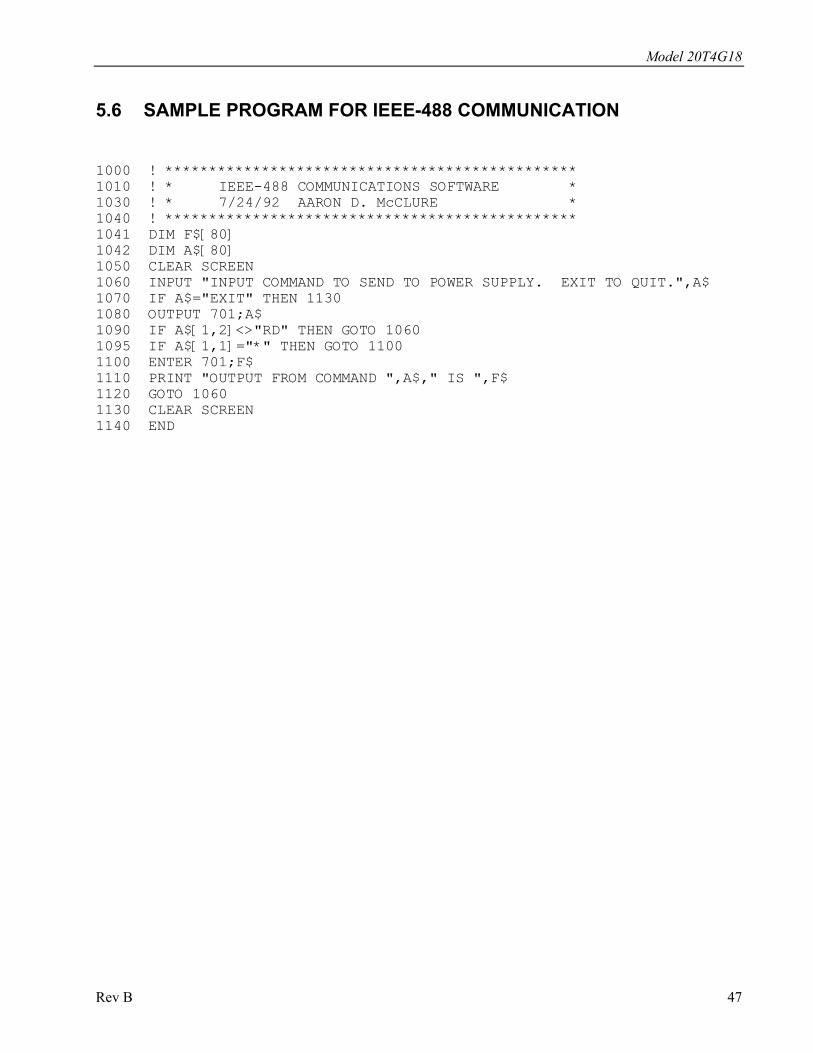
Model 20T4G18
5.6 SAMPLE PROGRAM FOR IEEE-488 COMMUNICATION
1000 ! *********************************************** 1010 ! * IEEE-488 COMMUNICATIONS SOFTWARE * 1030 ! * 7/24/92 AARON D. McCLURE * 1040 ! *********************************************** 1041 DIM F$[80] 1042 DIM A$[80] 1050 CLEAR SCREEN 1060 INPUT "INPUT COMMAND TO SEND TO POWER SUPPLY. EXIT TO QUIT.",A$ 1070 IF A$="EXIT" THEN 1130 1080 OUTPUT 701;A$ 1090 IF A$[1,2]<>"RD" THEN GOTO 1060 1095 IF A$[1,1]="*" THEN GOTO 1100 1100 ENTER 701;F$ 1110 PRINT "OUTPUT FROM COMMAND ",A$," IS ",F$ 1120 GOTO 1060 1130 CLEAR SCREEN 1140 END
Rev B 47

Model 20T4G18
48 Rev B

WARRANTIES: LIMITATION OF LIABILITY
Seller warrants (i) that seller has title to the goods sold and (ii) that Amplifiers, Antennas, Pre-compliance Test Systems, Transient Generators, Power Meters, Directional Couplers and Tripods will be free from defects in material and workmanship for a period of three (3) years from date of shipment shown on Amplifier Research invoice. Field Monitoring Equipment, Teseo Fiberoptic Systems and Traveling Wave Tubes in the 200T1G3A, 200T2G8A and 200T8G18A will be free from defects in material and workmanship for a period of two (2) years from date of shipment. Vacuum tubes, traveling-wave tubes in models not previously listed and power heads will be free from defects in material and workmanship for a period of one (1) year. Contact Amplifier Research for warranty information regarding items not listed. Seller’s sole responsibility in fulfilling these warranties shall be to repair or replace any goods which do not conform to the foregoing warranties or, at seller’s option, to give buyer credit for defective goods. The warranty is valid only when used in the country specified at time of order. Warranty service must be obtained from the repair facility designated at that time. If warranty service is not available in the country where the equipment is to be used, it must be returned to Amplifier Research. Warranty service will be provided only for defective goods which are returned within the warranty period, freight costs prepaid to Amplifier Research or its designated repair facility.
There are no other warranties, express or implied, including any warranty of merchantability or fitness. Seller shall not be responsible for any incidental or consequential damages arising from any breach of warranty.
No person other than an officer of Amplifier Research Corporation, has any authority to bind seller to any affirmation, representation or warranty except as specifically included in the preceding terms and conditions.
REV0701