Embed Size (px)
Citation preview
© EMC TEST SYSTEMS, L.P. – MARCH 2002 REV C – PN 399258
Model 3140
BiConiLog™ Antenna MANUAL
MODEL 3140 BICONILOG ™ ANTENNA
© EMC TEST SYSTEMS, L.P. – MARCH 2002 REV C – PN 399258
EMC Test Systems, L.P. reserves the right to make changes to any product described herein in order to improve function, design or for any other reason. Nothing contained herein shall constitute EMC Test Systems, L.P. assuming any liability whatsoever arising out of the application or use of any product or circuit described herein. EMC Test Systems, L.P. does not convey any license under its patent rights or the rights of others.
© Copyright 2002 by EMC Test Systems, L.P. All Rights Reserved. No part of this document may be copied by any means
without written permission from EMC Test Systems, L.P. E-MAIL & INTERNET
[email protected] http://www.ets-lindgren.com
USA 1301 Arrow Point Dr., Cedar Park, TX 78613 P.O. Box 80589, Austin, TX 78708-0589 Tel 512.531.6400 Fax 512.531.6500
FINLAND Euroshield OY Mekannikontie 1 27510, Eura, Finland Tel 358.2.838.3300 Fax 358.2.865.1233
SINGAPORE Lindgren RF Enclosures Asia-Pacific 87 Beach Road #06-02 Chye Sing Building Singapore 189695 Tel 65.536.7078 Fax 65.536.7093

MODEL 3140 BICONILOG™ ANTENNA
© EMC TEST SYSTEMS, L.P. – MARCH 2002 REV C – PN 399258
Table of Contents
INTRODUCTION............................................................................................................ 1
ASSEMBLY INSTRUCTIONS ...................................................................................... 4
MOUNTING INSTRUCTIONS ..................................................................................... 8
APPLICATION.............................................................................................................. 12
TYPICAL DATA ........................................................................................................... 14
SPECIFICATIONS........................................................................................................ 18
MAINTENANCE........................................................................................................... 19
WARRANTY STATEMENT........................................................................................ 20

MODEL 3140 BICONILOG ™ ANTENNA
© EMC TEST SYSTEMS, L.P. – MARCH 2002 REV C – PN 399258
MODEL 3140 BICONILOG™ ANTENNA Introduction
© EMC TEST SYSTEMS, L.P. – MARCH 2002 1 REV C – PN 399258
INTRODUCTION
The ETS-Lindgren EMCO brand Model 3140 is a high-
field addition to the popular bow-tie/log periodic
combination BiConiLogTM family, providing the highest
field-to-power ratio at low frequencies of any of the
BiConiLog™ antennas. The Model 3140 is designed
specifically to generate the field levels required for
immunity/susceptibility tests required by standards such as
IEC/EN 61000-4-3 using the lowest amount of input power
possible.
A BiConiLog™ antenna combines a broadband biconical-
like bow-tie antenna with a standard LPDA (log periodic
dipole array) to replace the traditional use of two antennas
in the 26-1000 MHz EMC test frequency range. Many
EMC antennas are variations of a standard tuned dipole,
which must be nearly half a wavelength long to transmit or
receive energy most efficiently. Thus, at 26 MHz, a tuned
dipole would have to be approximately 5.3 meters long,
about 4.6 meters long at 30 MHz, and 2.8 meters long at 50
MHz. Unfortunately, this is too unwieldy for many
anechoic chambers and test sites. The end plates of the
Model 3140 T bow-ties make the bow-tie antenna segment
look like an antenna twice as long as its 1.6 meter length.
The result is about a 10-dB improvement in low frequency
transmit gain compared to a same-length regular bow-tie.
Although bow-ties have been used for all of the elements
on some log-periodic antenna designs in the past, in EMC
applications the advantage gained is an extension of the
Introduction MODEL 3140 BICONILOG™ ANTENNA
2 © EMC TEST SYSTEMS, L.P. – MARCH 2002 REV C – PN 399258
useful low frequency range of the typical LPDA's from
100 MHz down to 26 MHz. At 26 MHz, an efficient single
dipole type antenna must be over 5 meters long, whereas
suitable performance is obtained here with a 1.6 meter long
bow-tie. A simple wire outline bow-tie antenna is
narrowband compared to a sheet bow-tie or biconical, thus
struts are added to the Model 3140 bow-ties to better
simulate the broadband sheet bow-tie.
The unique feature of the Model 3140 is the T bow-tie
elements. A T bow-tie increases the equivalent dipole
electrical length, thereby decreasing resonant frequency
and increasing efficiency in the 20-60 MHz range.
Similarly, a regular bow-tie has a lower resonant frequency
than an equal length single-wire dipole. The T bow-tie has
its first resonance at a frequency where its length is about
0.22λ, a regular bow-tie at a length of 0.3λ, and a tuned
dipole at about a length of 0.48λ. Thus at 50 MHz the 1.4
m long T bow-tie of the Model 3140 behaves like a 2.8 m
tuned dipole. Cross-polar radiation is minimized because
current flow on one of the T end frames is almost exactly
cancelled by the oppositely-phased current on the other T
end.
The standard "self-balun" feed of the log-periodic also
provides a matched balanced feed to the bow-tie elements.
To prevent cable pickup below 100 MHz, and to improve
matching to the bow-tie elements, the Model 3140 contains
a "balun" transformer which acts as a common-mode choke
to keep unbalanced current off the coaxial feed cable outer
shield, as well as adding some additional inductance to
MODEL 3140 BICONILOG™ ANTENNA Introduction
© EMC TEST SYSTEMS, L.P. – MARCH 2002 3 REV C – PN 399258
improve impedance matching to the bow-ties. Even though
the Model 3140 is highly balanced (symmetry +/- 0.5 dB),
in vertically polarized measurements cable position can
effect results, so it is recommended that the cable be
suspended horizontally back from the antenna at least 1
meter before any vertical drop. Below 150 MHz, bow-tie
radiation dominates with a dipole-like pattern, while above
150 MHz the radiation in the plane of the elements is
directional.
The antenna has dual mounting bracket and 1/4x20 UNC
knob for attaching to ETS-Lindgren tripod and tower
adapters. The brackets are spaced to align with the
mounting holes on the Model 7-TR tripod and the ETS-
Lindgren towers. Typical antenna factor data is included in
Figure 11.
Note: The Model 3140 is designed only for immunity
testing. The large size of the antenna makes it impractical
for emissions testing where height scanning is required,
and the bow-tie end plates increase the measurement
uncertainty when the antenna is polarized vertically. Thus,
individual calibrations are not provided for the Model
3140.
Assembly Instructions MODEL 3140 BICONILOG™ ANTENNA
4 © EMC TEST SYSTEMS, L.P. – MARCH 2002 REV C – PN 399258
ASSEMBLY INSTRUCTIONS
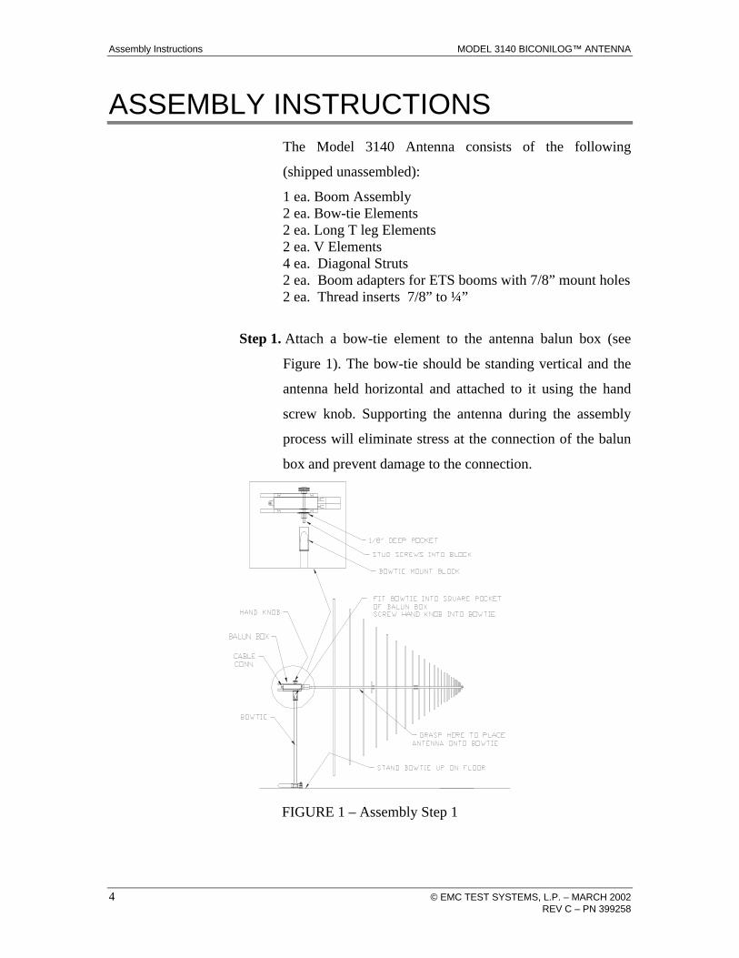
The Model 3140 Antenna consists of the following
(shipped unassembled):
1 ea. Boom Assembly 2 ea. Bow-tie Elements 2 ea. Long T leg Elements 2 ea. V Elements 4 ea. Diagonal Struts 2 ea. Boom adapters for ETS booms with 7/8” mount holes 2 ea. Thread inserts 7/8” to ¼”
Step 1. Attach a bow-tie element to the antenna balun box (see
Figure 1). The bow-tie should be standing vertical and the
antenna held horizontal and attached to it using the hand
screw knob. Supporting the antenna during the assembly
process will eliminate stress at the connection of the balun
box and prevent damage to the connection.
FIGURE 1 – Assembly Step 1
MODEL 3140 BICONILOG™ ANTENNA Assembly Instructions
© EMC TEST SYSTEMS, L.P. – MARCH 2002 5 REV C – PN 399258
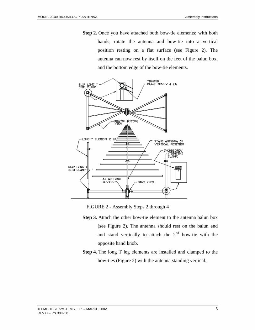
Step 2. Once you have attached both bow-tie elements; with both
hands, rotate the antenna and bow-tie into a vertical
position resting on a flat surface (see Figure 2). The
antenna can now rest by itself on the feet of the balun box,
and the bottom edge of the bow-tie elements.
FIGURE 2 - Assembly Steps 2 through 4
Step 3. Attach the other bow-tie element to the antenna balun box
(see Figure 2). The antenna should rest on the balun end
and stand vertically to attach the 2nd bow-tie with the
opposite hand knob.
Step 4. The long T leg elements are installed and clamped to the
bow-ties (Figure 2) with the antenna standing vertical.

Assembly Instructions MODEL 3140 BICONILOG™ ANTENNA
6 © EMC TEST SYSTEMS, L.P. – MARCH 2002 REV C – PN 399258
Step 5. The four diagonal struts should be installed. Loosen the
thumbscrews at the mount on the T legs and at the boom
mounts to install the strut ends. Place the pocket of the
straight end facing the raised face of each mount and
tighten the thumbscrew to lock in place (see Figure 3).
FIGURE 3 – Assembly Step 5
MODEL 3140 BICONILOG™ ANTENNA Assembly Instructions
© EMC TEST SYSTEMS, L.P. – MARCH 2002 7 REV C – PN 399258
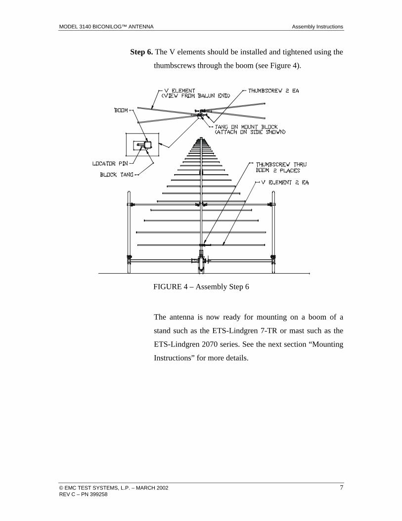
Step 6. The V elements should be installed and tightened using the
thumbscrews through the boom (see Figure 4).
FIGURE 4 – Assembly Step 6
The antenna is now ready for mounting on a boom of a
stand such as the ETS-Lindgren 7-TR or mast such as the
ETS-Lindgren 2070 series. See the next section “Mounting
Instructions” for more details.
Mounting Instructions MODEL 3140 BICONILOG™ ANTENNA
8 © EMC TEST SYSTEMS, L.P. – MARCH 2002 REV C – PN 399258
MOUNTING INSTRUCTIONS
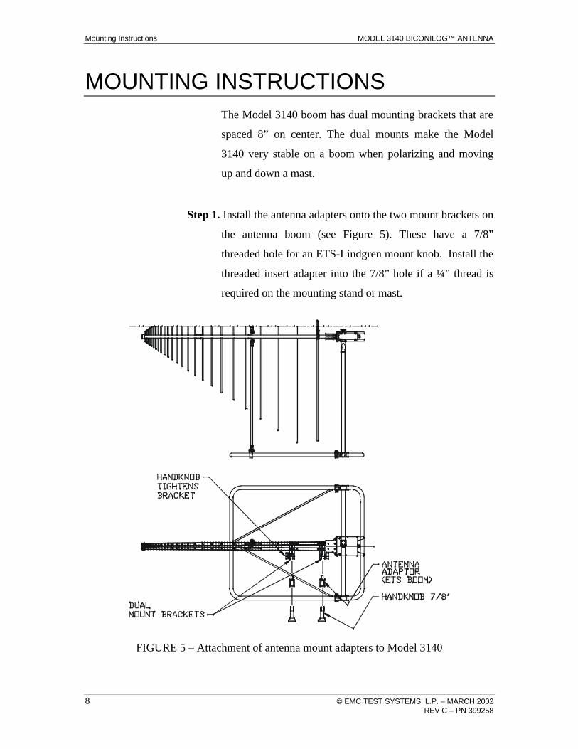
The Model 3140 boom has dual mounting brackets that are
spaced 8” on center. The dual mounts make the Model
3140 very stable on a boom when polarizing and moving
up and down a mast.
Step 1. Install the antenna adapters onto the two mount brackets on
the antenna boom (see Figure 5). These have a 7/8”
threaded hole for an ETS-Lindgren mount knob. Install the
threaded insert adapter into the 7/8” hole if a ¼” thread is
required on the mounting stand or mast.
FIGURE 5 – Attachment of antenna mount adapters to Model 3140
MODEL 3140 BICONILOG™ ANTENNA Mounting Instructions
© EMC TEST SYSTEMS, L.P. – MARCH 2002 9 REV C – PN 399258
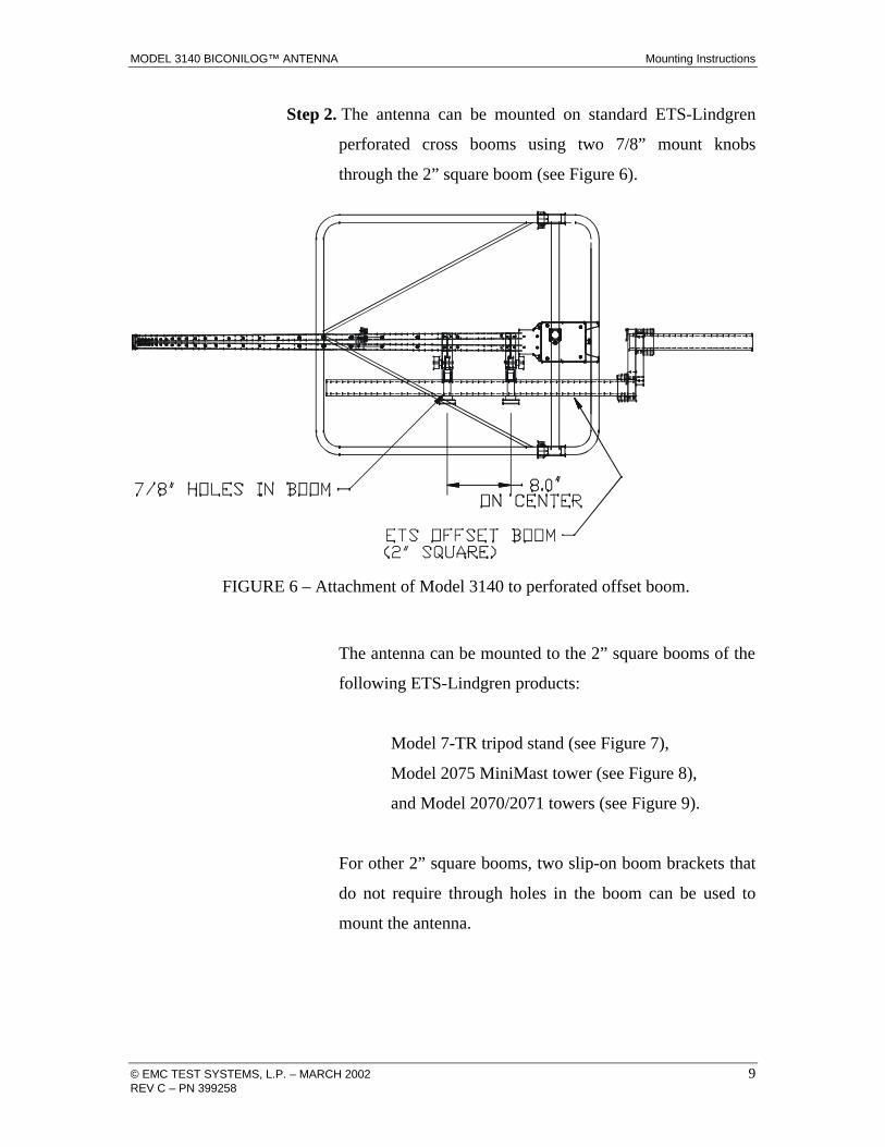
Step 2. The antenna can be mounted on standard ETS-Lindgren
perforated cross booms using two 7/8” mount knobs
through the 2” square boom (see Figure 6).
FIGURE 6 – Attachment of Model 3140 to perforated offset boom.
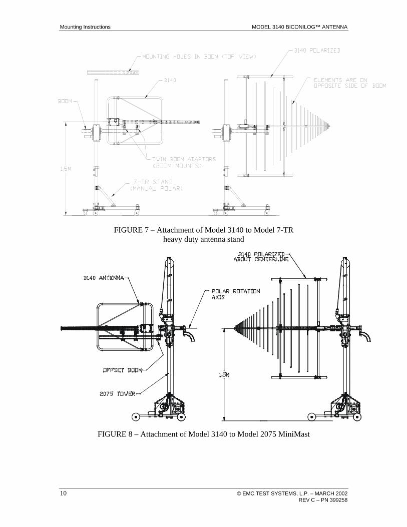
The antenna can be mounted to the 2” square booms of the
following ETS-Lindgren products:
Model 7-TR tripod stand (see Figure 7),
Model 2075 MiniMast tower (see Figure 8),
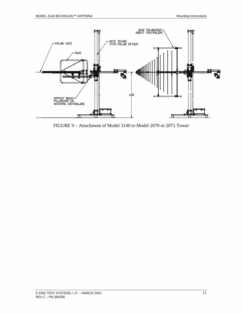
and Model 2070/2071 towers (see Figure 9).
For other 2” square booms, two slip-on boom brackets that
do not require through holes in the boom can be used to
mount the antenna.
Mounting Instructions MODEL 3140 BICONILOG™ ANTENNA
10 © EMC TEST SYSTEMS, L.P. – MARCH 2002 REV C – PN 399258
FIGURE 7 – Attachment of Model 3140 to Model 7-TR
heavy duty antenna stand
FIGURE 8 – Attachment of Model 3140 to Model 2075 MiniMast
MODEL 3140 BICONILOG™ ANTENNA Mounting Instructions
© EMC TEST SYSTEMS, L.P. – MARCH 2002 11 REV C – PN 399258
FIGURE 9 – Attachment of Model 3140 to Model 2070 or 2071 Tower
Application MODEL 3140 BICONILOG™ ANTENNA
12 © EMC TEST SYSTEMS, L.P. – MARCH 2002 REV C – PN 399258
APPLICATION
Assemble and mount the Model 3140 per the instructions in
the previous sections. Connect an N-type coaxial cable
from the antenna connector to a signal generator or
amplifier. Contact with any metal or non-metallic structure
can capacitively load the antenna, which may cause
unrepeatable results. Therefore, care must be taken to
ensure that no part of the dipole elements or bow-ties are in
contact with the tripod or tower, particularly in vertically-
polarized tests. Where possible, run the feed cable straight
back at least 1 meter or more from the Model 3140 before
dropping vertically.
Both horizontal and vertical polarization is easily
accomplished when the Model 3140 is mounted on an
ETS-Lindgren tower. The Model 7-TR tripod is designed
specifically for the T bow-tie BiConiLog™ antennas to
allow easy polarization changes, and with the air
polarization option can provide automated polarization
using a Model 2090 controller. The previous section
“Mounting Instructions” shows the mounting scheme for
both ETS-Lindgren towers and the 7-TR tripod.
For immunity testing, the electric field strength generated
at a distance d can be approximated by the formula
( )EPg
dV / m =
30
where d is in meters, g is the numeric gain (10G[dB]/10,
see attached calibration data), and P is antenna net input
power in Watts. An estimate of the power required for any
MODEL 3140 BICONILOG™ ANTENNA Application
© EMC TEST SYSTEMS, L.P. – MARCH 2002 13 REV C – PN 399258
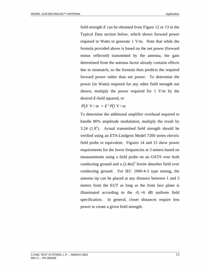
field strength E can be obtained from Figure 12 or 13 in the
Typical Data section below, which shows forward power
required in Watts to generate 1 V/m. Note that while the
formula provided above is based on the net power (forward
minus reflected) transmitted by the antenna, the gain
determined from the antenna factor already contains effects
due to mismatch, so the formula then predicts the required
forward power rather than net power. To determine the
power (in Watts) required for any other field strength not
shown, multiply the power required for 1 V/m by the
desired E-field squared, or
( ) ( )P E E PV / m V / m= 2 1
To determine the additional amplifier overhead required to
handle 80% amplitude modulation, multiply the result by
3.24 (1.82). Actual transmitted field strength should be
verified using an ETS-Lindgren Model 7200 series electric
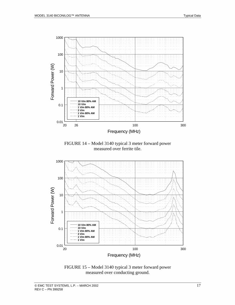
field probe or equivalent. Figures 14 and 15 show power
requirements for the lower frequencies at 3 meters based on
measurements using a field probe on an OATS over both
conducting ground and a (2.4m)2 ferrite absorber field over
conducting ground. For IEC 1000-4-3 type testing, the
antenna tip can be placed at any distance between 1 and 3
meters from the EUT as long as the front face plane is
illuminated according to the -0, +6 dB uniform field
specification. In general, closer distances require less
power to create a given field strength.
Typical Data MODEL 3140 BICONILOG™ ANTENNA
14 © EMC TEST SYSTEMS, L.P. – MARCH 2002 REV C – PN 399258
TYPICAL DATA
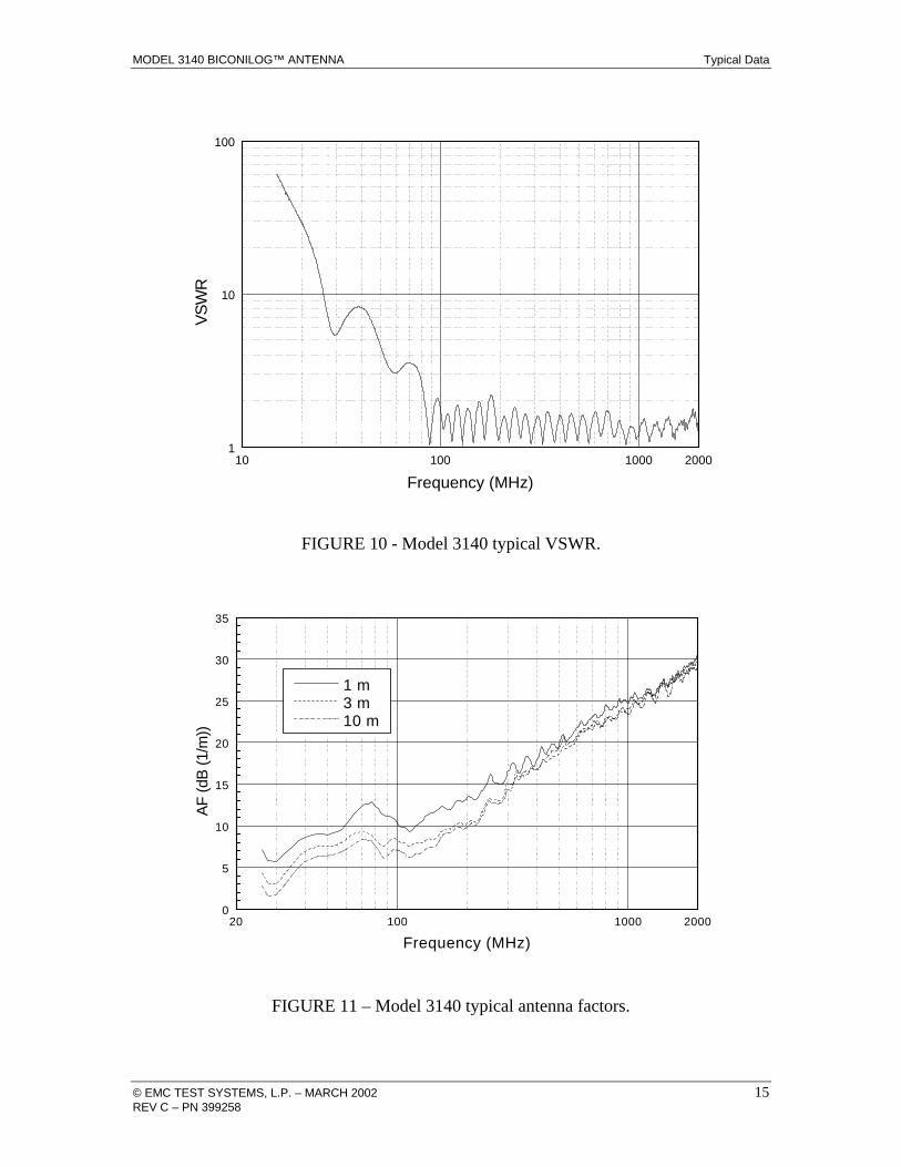
Figure 10 shows the typical VSWR for the Model 3140 in
the frequency range from 26-2000 MHz. Figure 11 shows
the typical horizontal antenna factors for the 3140 in the
same range. The separation distance for the ANSI C63.5 3
and 10 meter calibrations is measured from the antenna
midpoint, while for SAE/ARP-958 1 meter calibrations the
distance is measured from the antenna tip. Midpoint is
defined as half the distance between the small elements and
the bow-ties, which is about 65 cm from the small end tip.
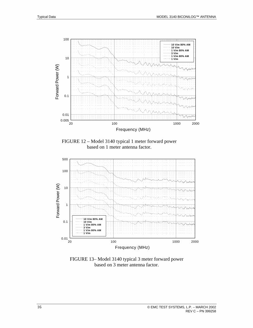
Figure 12 shows the typical forward power required for 1,
3, and 10 V/m (with and without 80% amplitude
modulation) at 1 meter from the tip of the antenna, while
Figure 13 is for 3 meters from the antenna tip. Figures 14
and 15 show power requirements for the lower frequencies
at 3 meters based on measurements using a field probe on
an OATS over both conducting ground and a (2.4m)2 ferrite
absorber field over conducting ground. The power shown
was measured with 1.5 meter transmit antenna and probe
height and horizontal polarization. Horizontal polarization
represents the worst-case power requirement; typically less
power is required for vertical polarization. In practice,
many users place ferrite tiles on the ground between the
antenna and probe to reduce reflected-ray interference. For
any other field strength E, multiply the power in Watts for
1 V/m by E2.
MODEL 3140 BICONILOG™ ANTENNA Typical Data
© EMC TEST SYSTEMS, L.P. – MARCH 2002 15 REV C – PN 399258
10 100 1000 20001
10
100
VS
WR
Frequency (MHz)
FIGURE 10 - Model 3140 typical VSWR.
20 100 1000 20000
5
10
15
20
25
30
35
1 m 3 m 10 m
AF
(dB
(1/m
))
Frequency (MHz)
FIGURE 11 – Model 3140 typical antenna factors.
Typical Data MODEL 3140 BICONILOG™ ANTENNA
16 © EMC TEST SYSTEMS, L.P. – MARCH 2002 REV C – PN 399258
20 100 1000 20000.005
0.01
0.1
1
10
100
10 V/m 80% AM 10 V/m 1 V/m 80% AM 3 V/m 1 V/m 80% AM 1 V/m
Forw
ard
Pow
er (W
)
Frequency (MHz)
FIGURE 12 – Model 3140 typical 1 meter forward power
based on 1 meter antenna factor.
20 100 1000 20000.01
0.1
1
10
100
500
10 V/m 80% AM 10 V/m 1 V/m 80% AM 3 V/m 1 V/m 80% AM 1 V/m
Forw
ard
Pow
er (W
)
Frequency (MHz)
FIGURE 13– Model 3140 typical 3 meter forward power
based on 3 meter antenna factor.
MODEL 3140 BICONILOG™ ANTENNA Typical Data
© EMC TEST SYSTEMS, L.P. – MARCH 2002 17 REV C – PN 399258
20 26 100 3000.01
0.1
1
10
100
1000
10 V/m 80% AM 10 V/m 1 V/m 80% AM 3 V/m 1 V/m 80% AM 1 V/m
Forw
ard
Pow
er (W
)
Frequency (MHz)
FIGURE 14 – Model 3140 typical 3 meter forward power
measured over ferrite tile.
20 100 3000.01
0.1
1
10
100
1000
10 V/m 80% AM 10 V/m 1 V/m 80% AM 3 V/m 1 V/m 80% AM 1 V/m
Forw
ard
Pow
er (W
)
Frequency (MHz)
FIGURE 15 – Model 3140 typical 3 meter forward power
measured over conducting ground.
Specifications MODEL 3140 BICONILOG™ ANTENNA
18 © EMC TEST SYSTEMS, L.P. – MARCH 2002 REV C – PN 399258
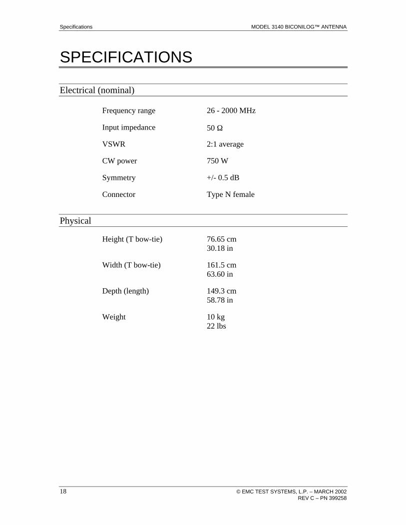
SPECIFICATIONS
Electrical (nominal)
Frequency range
26 - 2000 MHz
Input impedance
50 Ω
VSWR
2:1 average
CW power
750 W
Symmetry
+/- 0.5 dB
Connector Type N female
Physical
Height (T bow-tie) 76.65 cm 30.18 in
Width (T bow-tie) 161.5 cm 63.60 in
Depth (length) 149.3 cm 58.78 in
Weight 10 kg 22 lbs

MODEL 3140 BICONILOG™ ANTENNA Maintenance
© EMC TEST SYSTEMS, L.P. – MARCH 2002 19 REV C – PN 399258
MAINTENANCE
The ETS-Lindgren EMCO brand Model 3140 was designed
to be used for Immunity testing. Because the testing is for
immunity, the generated field is measured with a calibrated
field probe, not the Model 3140. Thus it is not required that
the Model 3140 be recalibrated regularly. If you would like
to have your Model 3140 antenna verified or serviced
please contact our Calibration Department.
For more information about our calibration services or to
place an order for antenna calibration, visit our calibration
website at http://antennacalibration.com/

Warranty Statement MODEL 3140 BICONILOG™ ANTENNA
20 © EMC TEST SYSTEMS, L.P. – MARCH 2002 REV C – PN 399258
WARRANTY STATEMENT
EMC Test Systems, L.P., hereinafter referred to as the Seller, warrants that standard EMCO products are free from defect in materials and workmanship for a period of two (2) years from date of shipment. Standard EMCO Products include the following: v Antennas, Loops, Horns v GTEM cells, TEM cells, Helmholtz Coils v LISNs, PLISNs, Rejection cavities & Networks v Towers, Turntables, Tripods & Controllers v Field Probes, Current Probes, Injection Probes
If the Buyer notifies the Seller of a defect within the warranty period, the Seller will, at the Seller’s option, either repair and/or replace those products that prove to be defective.
There will be no charge for warranty services performed at the location the Seller designates. The Buyer must, however, prepay inbound shipping costs and any duties or taxes. The Seller will pay outbound shipping cost for a carrier of the Seller’s choice, exclusive of any duties or taxes. If the Seller determines that warranty service can only be performed at the Buyer’s location, the Buyer will not be charged for the Seller’s travel related costs.
This warranty does not apply to:
v Normal wear and tear of materials v Consumable items such as fuses, batteries, etc. v Products that have been improperly installed, maintained or used v Products which have been operated outside the specifications v Products which have been modified without authorization v Calibration of products, unless necessitated by defects
THIS WARRANTY IS EXCLUSIVE. NO OTHER WARRANTY, WRITTEN OR ORAL, IS EXPRESSED OR IMPLIED, INCLUDING BUT NOT LMITED TO, THE IMPLIED WARRANTIES OF MERCHANTABILITY AND FITNESS FOR A PARTICULAR PURPOSE. THE REMEDIES PROVIDED BY THIS WARRANTY ARE THE BUYER’S SOLE AND EXCLUSIVE REMEDIES. IN NO EVENT IS THE SELLER LIABLE FOR ANY DAMAGES WHATSOEVER, INCLUDING BUT NOT LIMITED TO, DIRECT, INDIRECT, SPECIAL, INCIDENTAL, OR CONSEQUENTIAL DAMAGES, WHETHER BASED ON CONTRACT, TORT, OR ANY OTHER LEGAL THEORY.
Note: Please contact the Seller’s sales department for a Return Materials Authorization (RMA) number before shipping equipment to us.