Embed Size (px)
Citation preview
© EMC TEST SYSTEMS, L.P. – SEPTEMBER 2002 REV E – PN 399034
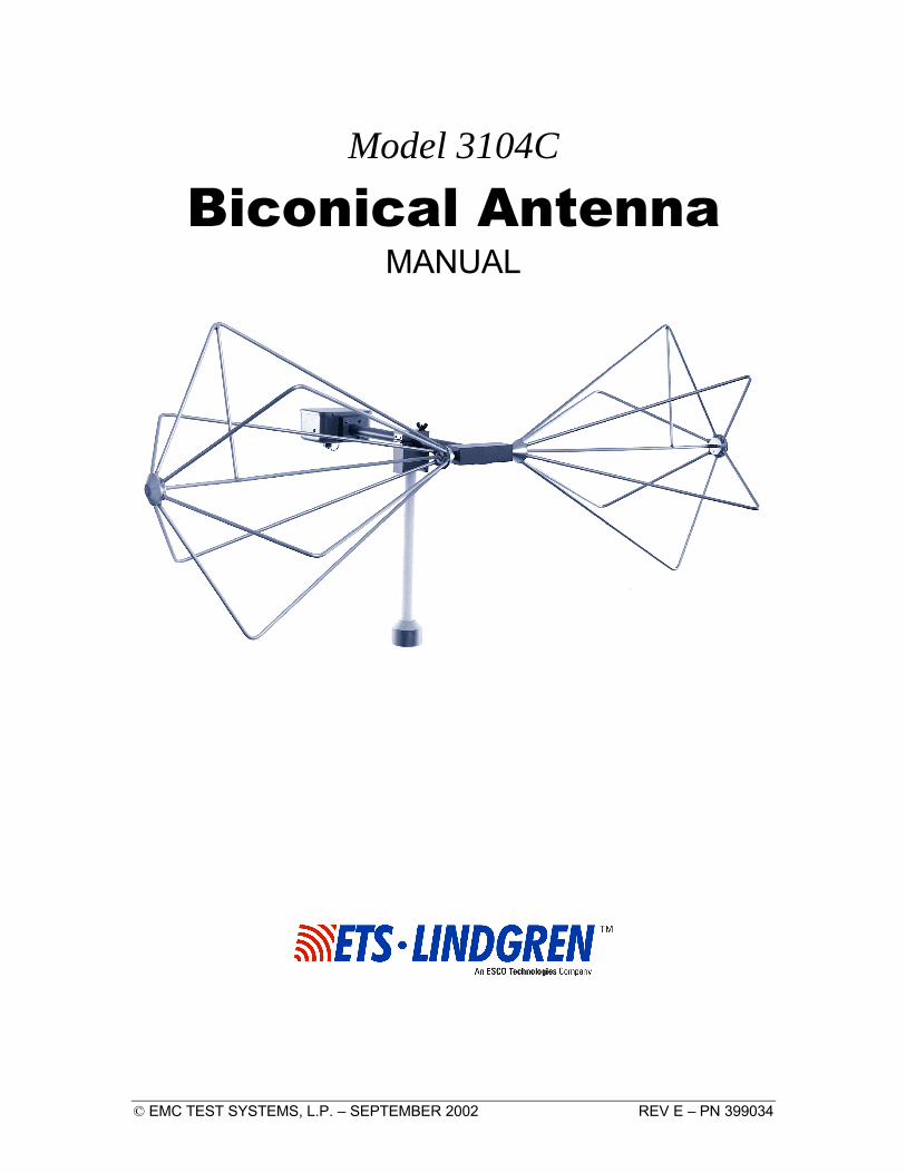
Model 3104C
Biconical Antenna MANUAL

MODEL 3104C BICONICAL ANTENNA
© EMC TEST SYSTEMS, L.P. – SEPTEMBER 2002 REV E – PN 399034
EMC Test Systems, L.P. reserves the right to make changes to any products herein to improve functioning, design, or for any other reason. Nothing contained herein shall constitute EMC Test Systems, L.P. assuming any liability whatsoever arising out of the application or use of any product or circuit described herein. EMC Test Systems, L.P. does not convey any license under its patent rights or the rights of others.
© Copyright 2002 by EMC Test Systems, L.P. All Rights Reserved. No part of this document may be copied by any means
without written permission from EMC Test Systems, L.P.
E-MAIL & INTERNET [email protected] http://www.ets-lindgren.com
USA 1301 Arrow Point Dr., Cedar Park, TX 78613 P.O. Box 80589, Austin, TX 78708-0589 Tel 512.531.6400 Fax 512.531.6500
FINLAND Euroshield OY Mekaanikontie 1 27510, Eura, Finland Tel 358.2.838.3300 Fax 358.2.865.1233
SINGAPORE Lindgren RF Enclosures Asia-Pacific 87 Beach Road #06-02 Chye Sing Building Singapore 189695 Tel 65.536.7078 Fax 65.536.7093

MODEL 3104C BICONICAL ANTENNA
© EMC TEST SYSTEMS, L.P. – SEPTEMBER 2002 REV E – PN 399034
Table of Contents
INTRODUCTION.................................................................................................................................. 1
STANDARD CONFIGURATION ......................................................................................................... 2
OPTIONS ............................................................................................................................................... 2
ASSEMBLY INSTRUCTIONS.............................................................................................................. 4
MOUNTING INSTRUCTIONS............................................................................................................. 5
OPERATION ......................................................................................................................................... 5
TYPICAL DATA.................................................................................................................................... 6
SPECIFICATIONS .............................................................................................................................. 10
ELECTRICAL ....................................................................................................................................... 10 PHYSICAL ........................................................................................................................................... 10
MAINTENANCE ................................................................................................................................. 11
WARRANTY........................................................................................................................................ 12

MODEL 3104C BICONICAL ANTENNA
© EMC TEST SYSTEMS, L.P. – SEPTEMBER 2002 REV E – PN 399034
MODEL 3104C BICONICAL ANTENNA Introduction
© EMC TEST SYSTEMS, L.P. – SEPTEMBER 2002 1 REV E – PN 399034
INTRODUCTION The ETS-Lindgren Model 3104C Biconical Antenna is designed to operate over the 20 to 200 MHz frequency range to meet Military and DOD EMI specifications. It is of lightweight construction for ease in handling and storage. The biconical elements are made from welded aluminum. The elements mount in a balun network which is fabricated of phenolic and is equipped with the necessary impedance-matching components. The Model 3104C is designed and precisely manufactured to conform to the requirements of MIL-STD-461 and other Military Standards as reflected in Drawing ES-F-201286. Each antenna is individually calibrated during the manufacturing process. The results of these calibrations are tabulated and included with the antenna as gain and antenna factor vs. frequency data for use in specification compliance testing.

Standard Configuration MODEL 3104C BICONICAL ANTENNA
2 © EMC TEST SYSTEMS, L.P. – SEPTEMBER 2002 REV E – PN 399034
STANDARD CONFIGURATION
• Antenna Elements • Balun • Clamp Block • Individually calibrated at 1 m per SAE ARP 958 and 3 and
10m per ANSI C63.5. Actual factors and a signed Certificate of Calibration Conformance included.
OPTIONS Portable Elements (P): Collapsible folding elements are available, making the antennas portable and ideal for field use. Both the standard rigid and optional folding elements attach to the balun using screw mounts. This makes interchanging between the elements very quick and easy. Optional carrying cases are available to further enhance portability. Extended Portable Elements (XP): An extended version of the portable elements is available. These folding elements are twice as long as the standard elements. The longer elements enable you to generate high fields at low frequencies with reduced applied power. Carrying Cases: Carrying cases for portable elements and biconical antenna are readily available. Support Rod: Antenna mount with insert designed to accept ETS-Lindgren or other tripod with ¼” x 20 threads Tripods: ETS-Lindgren offers two nonmetallic, non-reflective tripods for use at both indoor and outdoor EMC test sites. The Model 4-TR, constructed of linen phenolic and delrin, is designed with an adjustable center post for precise height adjustments. Maximum height for the 4-TR is 2.0 m (80.0 in), while minimum height is 94 cm (37.0 in). This tripod can support up to an 11.8 kg (26.0 lb) load.
MODEL 3104C BICONICAL ANTENNA Options
© EMC TEST SYSTEMS, L.P. – SEPTEMBER 2002 3 REV E – PN 399034
The 7-TR tripod has several different configurations, including options for manual or pneumatic polarization. This tripod provides increased stability for physically large antennas. Its unique design allows for quick assembly/disassembly and convenient storage. Quick height adjustment and locking wheels provide ease of use during testing. This tripod can support up to a 13.5 kg (30.0 lb) load. For the 7-TR series, maximum height is 2.17 m (85.8 in), with a minimum height of 0.8 m (31.8 in). The 7-TR is constructed of PVC and fiberglass components.

Assembly Instructions MODEL 3104C BICONICAL ANTENNA
4 © EMC TEST SYSTEMS, L.P. – SEPTEMBER 2002 REV E – PN 399034
ASSEMBLY INSTRUCTIONS The Model 3104C consists of the following (shipped unassembled): 1 ea. Balun 2 ea. Biconical Elements 2 ea. Bellville Washers (In a small plastic bag) 1 ea. Mounting Clamp Step 1. After carefully unpacking all of the components, take one of the Bellville washers and slide it onto the threaded screw end of one of the biconical elements. Step2. Line up the screw threads with the receptacle hole on the balun and turn the biconical element until it is firmly secured in the balun. Be careful not to cross-thread this connection or permanent damage to the joint could occur. Step 3. Repeat steps 1 and 2 with the other washer and biconical element. Now you are ready to mount the antenna on a tripod for testing.
Belleville Washer Balun
Clamp (Open Position)
Biconical Element
Output Connector

MODEL 3104C BICONICAL ANTENNA Mounting Instructions
© EMC TEST SYSTEMS, L.P. – SEPTEMBER 2002 5 REV E – PN 399034
MOUNTING INSTRUCTIONS The mounting clamp of the Model 3104C uses standard 7/8x14 threads and comes with a 1/4x20 thread adapter for versatility when mounting on an ETS-Lindgren tripod or most other tripods for support. After the mounting clamp is attached to a tripod, unscrew the latch and open the clamp. Insert the balun of the Model 3104C into the clamp and close the top over the balun. Move the screw latch to the closed position and tighten, so the balun is held securely. The cable can now be attached to the output connector.
OPERATION The Model 3104C biconical antenna has a traditional coaxial wound balun which provides a broad frequency range and moderate gain for both transmitting and receiving. This antenna may be used for radiated immunity measurements provided that the peak input power is limited to no more than 100 W. For enhanced measurement repeatability it is recommended that when the Model 3104C is used vertically the same element orientation be maintained from measurement to measurement. A white strip or dimples on the element block mark the coax shield side of the element. Keeping this side towards ground when the antenna is used vertically will increase test repeatability especially when the Model 3104C is used inside a shielded enclosure.

Typical Data MODEL 3104C BICONICAL ANTENNA
6 © EMC TEST SYSTEMS, L.P. – SEPTEMBER 2002 REV E – PN 399034
TYPICAL DATA

MODEL 3104C BICONICAL ANTENNA Typical Data
© EMC TEST SYSTEMS, L.P. – SEPTEMBER 2002 7 REV E – PN 399034

Typical Data MODEL 3104C BICONICAL ANTENNA
8 © EMC TEST SYSTEMS, L.P. – SEPTEMBER 2002 REV E – PN 399034

MODEL 3104C BICONICAL ANTENNA Typical Data
© EMC TEST SYSTEMS, L.P. – SEPTEMBER 2002 9 REV E – PN 399034

Specifications MODEL 3104C BICONICAL ANTENNA
10 © EMC TEST SYSTEMS, L.P. – SEPTEMBER 2002 REV E – PN 399034
SPECIFICATIONS
ELECTRICAL Frequency Range 20-200 MHz Impedance Matched to 50 ohms VSWR Ratio (AVG) 2.8:1 Power Input Capability 50 Watts continuous power
100 Watts short term peak power
Connector Type N
PHYSICAL Length 143.5 cm (56.5 inches) Diameter 53.3 cm (21 inches) Depth 81.3 cm (32 inches) Weight 2.7 kg (6.0 lbs)

MODEL 3104C BICONICAL ANTENNA Maintenance
© EMC TEST SYSTEMS, L.P. – SEPTEMBER 2002 11 REV E – PN 399034
MAINTENANCE To ensure reliable and repeatable long-term performance, annual recalibration of your antennas by ETS-Lindgren’s experienced technicians is recommended. Our staff can recalibrate almost any type or brand of antenna. Please call to receive a service order number prior to sending an antenna to us for calibration. For more information about our calibration services or to place an order for antenna calibration visit our calibration website at http://www.antennacalibration.com/.

Warranty MODEL 3104C BICONICAL ANTENNA
12 © EMC TEST SYSTEMS, L.P. – SEPTEMBER 2002 REV E – PN 399034
WARRANTY
EMC Test Systems, L.P., hereinafter referred to as the Seller, warrants that standard EMCO products are free from defect in materials and workmanship for a period of two (2) years from date of shipment. Standard EMCO Products include the following: v Antennas, Loops, Horns v GTEM cells, TEM cells, Helmholtz Coils v LISNs, PLISNs, Rejection cavities & Networks v Towers, Turntables, Tripods & Controllers v Field Probes, Current Probes, Injection Probes
If the Buyer notifies the Seller of a defect within the warranty period, the Seller will, at the Seller’s option, either repair and/or replace those products that prove to be defective.
There will be no charge for warranty services performed at the location the Seller designates. The Buyer must, however, prepay inbound shipping costs and any duties or taxes. The Seller will pay outbound shipping cost for a carrier of the Seller’s choice, exclusive of any duties or taxes. If the Seller determines that warranty service can only be performed at the Buyer’s location, the Buyer will not be charged for the Seller’s travel related costs.
This warranty does not apply to:
v Normal wear and tear of materials v Consumable items such as fuses, batteries, etc. v Products that have been improperly installed, maintained or used v Products which have been operated outside the specifications v Products which have been modified without authorization v Calibration of products, unless necessitated by defects
THIS WARRANTY IS EXCLUSIVE. NO OTHER WARRANTY, WRITTEN OR ORAL, IS EXPRESSED OR IMPLIED, INCLUDING BUT NOT LMITED TO, THE IMPLIED WARRANTIES OF MERCHANTABILITY AND FITNESS FOR A PARTICULAR PURPOSE. THE REMEDIES PROVIDED BY THIS WARRANTY ARE THE BUYER’S SOLE AND EXCLUSIVE REMEDIES. IN NO EVENT IS THE SELLER LIABLE FOR ANY DAMAGES WHATSOEVER, INCLUDING BUT NOT LIMITED TO, DIRECT, INDIRECT, SPECIAL, INCIDENTAL, OR CONSEQUENTIAL DAMAGES, WHETHER BASED ON CONTRACT, TORT, OR ANY OTHER LEGAL THEORY.
Note: Please contact the Seller’s sales department for a Return Materials Authorization (RMA) number before shipping equipment to us.