Embed Size (px)
Citation preview
On the ECO2 multifunctional design paradigmand tools for acoustic tailoring
Juan Pablo Parra Martinez
Licentiate ThesisStockholm, 2015
Centre for ECO2 Vehicle DesignKTH Royal Institute of Technology
Teknikringen 8SE10044 Stockholm, Sweden
LAUM - UMR CNRS 6613Université du Maine
Avenue Olivier MessiænF72085 Le Mans Cedex France
Academic thesis with permission by KTH Royal Institute of Technology, Stockholm,to be submitted for public examination for the degree of Licentiate in Vehicle andMaritime Engineering.
ISSN 1651-7660TRITA-AVE 2015:08ISBN 978-91-7595-460-8
Author contact:+46 73 460 [email protected]@univ-lemans.fr
c©Juan Pablo Parra Martinez, 2015

“The feeling of awed wonder that science can give us is one ofthe highest experiences of which the human psyche is capable.It is a deep aesthetic passion to rank with the finest that musicand poetry can deliver. It is truly one of the things that makelife worth living and it does so, if anything, more effectively if itconvinces us that the time we have for living is quite finite.”
Richard Dawkins, Unweaving the Rainbow: Science, Delusion andthe Appetite for Wonder.
A Juanita

On the ECO2 multifunctional design paradigmand tools for acoustic tailoring
Juan Pablo Parra MartinezCenter for ECO2 Vehicle Design
& MWL Marcus Wallenberg Laboratory for Sound and VibrationDepartment of Aeronautical and Vehicle Engineering
School of Engineering SciencesRoyal Institute of Technology
Stockholm, Sweden
AbstractNowadays vehicle design paradigm influences not only the effectiveness of the
different means of transport, but also the environment and economy in a critical way.The assessment of the consequences that design choices have on society at largeare necessary to understand the limits of the methods and techniques currentlyemployed. One of the mechanisms set in motion is the planned obsolescence ofproducts and services. This has affected vehicle design paradigm in such a way thatthe variety in the market has shadowed the primary function of vehicle systems: thetransport of persons and goods. Amongst the consequences of the expansion of suchmarket is the exponential rise on combustion emissions to the atmosphere, whichhas become a great hindrance for humans health and survival of ecosystems. Thedevelopment of evaluation tools for such consequences and their piloting mechanismsis needed so as to implement an ECO2 (Ecological and Economical) vehicle designparadigm. Moreover, the multifunctional design paradigm that drives aeronauticaland vehicle engineering is an ever-growing demand of smart materials and structures,able to fulfil multiple requirements in an effective way. The understanding of certainphenomena intrinsic to the introduction of novel materials has found certain limitsdue to the complexity of the models needed. This work presents as a first stepan assessment of the causes and consequences of the vehicle exponential marketgrowth based on the analysis of the planned obsolescence within. Furthermore,a method for the acoustic response analysis of multilayered structures includinganisotropic poroelastic materials is introduced. The methodology consists in aplane wave approach as a base for introducing the complex mechanic and acousticequations governing anisotropic homogeneous media, e.g. open-celled foams, into analternative mathematical tool manipulating physical wave amplitudes propagationwithin the studied media. In addition, this method is coupled to a power partitioningand energetic assessment tool so as to understand the phenomena present in complexmultilayered designs.
Keywords: vehicle design, planned obsolescence, anisotropy, porous materials,sound absorbing materials, acoustic modelling, power balance, energy assessment,dissipated power.
i
SammanfattningI dagens samhälle påverkar det sätt fordon konstrueras påinte bara de olika
fordonsslagens effektivitet utan det har ocksåett avgörande inflytande påmiljönoch ekonomin. För att uppskatta begränsningarna i de olika metoder ochtekniker som för närvarande används samt hur de inverkar påsamhället somhelhet, behövs bedömningar av dess konsekvenser. En mekanism som harinförts är det planerade åldrandet av produkter och tjänster. Denna mekanismhar påverkat det sätt fordon konstrueras påtill den grad att fordonets primärafunktion, dvs att transportera personer och gods, har hamnat i skuggan avurvalet påmarknaden. Bland konsekvenserna av att fordonsmarknaden expanderaråterfinns de exponentiellt växande utsläppen av förbränningsavgaser i atmosfären,som har blivit ett stort hinder för människohälsan och ekosystemens överlevnad.Utvecklingen av verktyg för bedömning av sådana konsekvenser samt dess styrandemekanismer behövs för att kunna införa ett ECO2 (Ekologiskt och Ekonomiskt)sätt att konstruera fordon. Vidare såleder det multifunktionella tänkandet somdriver dagens fordonskonstruktioner till en ständigt växande efterfrågan påsmartamaterial och konstruktioner som kan uppfylla flera olika krav påett effektivt sätt.Den komplexitet som krävs för att modellera införandet av nya material leder tillen begränsning av förståelsen av vissa fenomen som uppkommer av införandet avde nya materialen. Baserad påen analys av det planerade åldrandet presenteras idenna avhandling först en bedömning av de orsaker och konsekvenser som kommer avfordonsmarknadens exponentiella ökning. Vidare introduceras en metod för akustiskresponsanalys av flerlager-strukturer inklusive anisotropiska poroelastiska material.Metoden grundar sig i ett planvågs-baserat tillvägagångssätt att introducera dekomplexa mekaniska och akustiska ekvationerna som styr anisotropiska homogenamedier, exempelvis skumplast med öppna celler, i ett alternativt matematisktverktyg som manipulerar utbredningen av vågamplituder i det studerade mediet.Denna metod är dessutom kopplad till ett bedömningsverktyg för effektdelning föratt förståde fenomen som finns i komplexa flerlager-konstruktioner.
ii
PrefaceThe work presented in this Licentiate thesis was funded by theCentre for ECO2 Vehicle Design and carried out as part of the internationalagreement of co-tutelle between the KTH Royal Institute of Technology (Stockholm,Sweden), and the Laboratoire d’Acoustique de l’Université du Maine (Le Mans,France).The main supervision of this work was performed by Prof. Peter Göransson(a)and Prof. Olivier Dazel(b) . The co-supervision was performed by Dr. JacquesCuenca(a)(c) and Assoc.-Prof. Per Wennhage(a), and made possible thanks to thecollaboration with Eng. Ulrika Ohlsson(d).The thesis consists in two parts. The first part gives an overview of the researchwith a summary of the work performed. The second part collects the followingscientific publications,
Paper I. J. P. Parra Martinez, P. Göransson, O. Dazel, and J. Cuenca, Analysis ofthe frequency response behaviour of anisotropic multilayered structures and potentialacoustic performance optimizations, in ISMA 2014 International Conference in Noiseand Vibration Engineering and USD 2014 International Conference on Uncertaintyin Structural Dynamics, Leuven, Belgium (2014) pp. 4375-4386.
Paper II. J. P. Parra Martinez, O. Dazel, P. Göransson, J. Cuenca,Acoustic behaviour and internal energies of multilayer systems including anisotropicporoelastic materials, to be submitted (2015).
Parra Martinez performed the analytical and numerical work for all thepublications, under the scientific methodology agreed upon with the co-authors, andmainly supervised by Dazel and Göransson. The methods and results were discussedand analysed by all authors, from where the first drafts of the publications weremade by the first author. Parra Martinez then produced the publications under theiterative supervision from all the co-authors. Additionally, the first publication waspresented in the conference therein stated by the author to the scientific community.
The following publication was not included in this thesis:
Paper III. J. P. Parra Martinez, O. Dazel, P. Göransson, and J. Cuenca, Poweranalysis computation of anisotropic porous materials within multilayered structuresbased on plane wave approximation, in Euronoise 2015, 10th European Congress andExposition on Noise Control Engineering, Maastricht, Netherlands (2015).
(a)KTH Royal Institute of Technology, Teknikringen 8, SE-10044 Stockholm, Sweden.(b)Laboratoire d’Acoustique de l’Université du Maine - UMR CNRS 6613, Avenue Olivier
Messiaen, F-72085 Le Mans Cedex France.(c)Siemens Industry Software, Interleuvenlaan 68, B-3001 Leuven, Belgium.(d)Volvo Group Trucks Technology, Dept BF71311, AB2N, 405 08 Göteborg, Sweden.

Contents
Part 1. Overview and Summary 1
Chapter 1. Introduction 31.1 Motivation . . . . . . . . . . . . . . . . . . . . . 31.2 Objectives . . . . . . . . . . . . . . . . . . . . . 5
Chapter 2. On the ECO2 design paradigm:Defining the concept of legal obsolescence trigger spiral and itsinfluence on current vehicle design 7
2.1 On planned Obsolescence . . . . . . . . . . . . . . . . 72.2 Legal obsolescence trigger spiral . . . . . . . . . . . . . 9
Chapter 3. Tools for acoustic design of multilayered structures 133.1 Acoustic response assessment . . . . . . . . . . . . . . 13
3.1.1 Formal approach . . . . . . . . . . . . . . . . . 133.1.2 Multilayered study case. . . . . . . . . . . . . . . 153.1.3 Results. . . . . . . . . . . . . . . . . . . . . 16
3.2 Calculation of the conservative and dissipative powers . . . . . 193.2.1 Calculation of quadratic quantities . . . . . . . . . . 193.2.2 Results. . . . . . . . . . . . . . . . . . . . . 20
Chapter 4. Conclusion & Discussion 23
Bibliography 25
Part 2. Appended publications 29
v


Part 1
Overview and Summary

CHAPTER 1
Introduction
1.1 MotivationIn the past decades, anthropogenic pollution has been assessed as the main cause
for extreme climate change. On-road pollution being accounted1 in some populatedareas for over 50% of VOC(a) and NOx
(b) emissions, the need for evaluating all theaspects in which aeronautical and vehicle design affects society and environment iscrucial.
The paradigm of vehicle design has then grown to inherently affect not onlythe socio-economical development of society at large, but also the ecosystems withwhich it interacts. Thus, vehicle industry has to deal with the hindrances of legalrequirements (regarding gas emissions and recyclability) whilst meeting up thechallenge of designing systems based on multifunctionality, packaging limitations,minimal energy consumption and reduced ecological impact.
To meet up its objectives, vehicle designers and manufacturers have includedtools to address the technical difficulties at stake. From an ECO2 (ecologicaland economical) perspective, the incorporation of Life Cycle Analysis or Designfor Environment methods to the vehicle design processes has been thoroughlystudied2? ,3. They aim to take into account an environmental impact projectionof production and use of vehicles so as to minimise ecological repercussion. Ona materials and structures perspective, the use of multilayered systems (so-calledsandwich panels) in vehicle designs has enabled the development of solutionsfor conserving a set of functional performances whilst reducing the weight, andtherefore decreasing the energy consumption of the vehicle.4–10. They were firstused in aeronautical applications, then in vas areas ranging from road and railvehicle engineering, naval architecture to modern building design. The designof such multifunctional structures presents a complex compromise between thematerials chosen, the topological arrangements, and the balance between weightand packaging. Thus, as the complexity of such systems increases, there is aneed for accurate modelling tools with relevant measures of their performance. Inapplications where these structures are part of the load carrying system, they aregenerally composed of face-sheets connected via a core, commonly made out ofporous foams or fibrous materials4–10.
(a)Volatile Organic Compound(b)Nitrogen Oxides
3
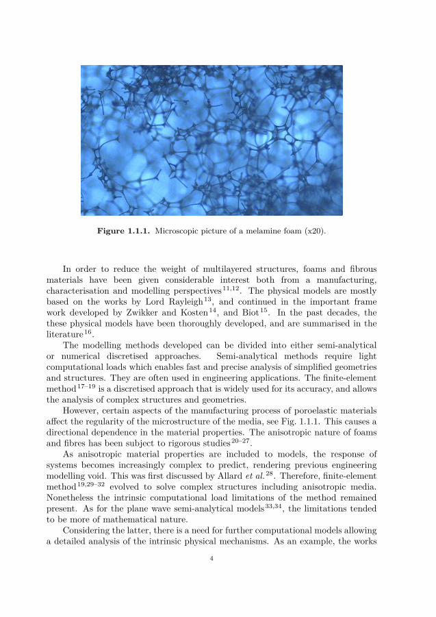
Figure 1.1.1. Microscopic picture of a melamine foam (x20).
In order to reduce the weight of multilayered structures, foams and fibrousmaterials have been given considerable interest both from a manufacturing,characterisation and modelling perspectives11,12. The physical models are mostlybased on the works by Lord Rayleigh13, and continued in the important framework developed by Zwikker and Kosten14, and Biot15. In the past decades, thethese physical models have been thoroughly developed, and are summarised in theliterature16.
The modelling methods developed can be divided into either semi-analyticalor numerical discretised approaches. Semi-analytical methods require lightcomputational loads which enables fast and precise analysis of simplified geometriesand structures. They are often used in engineering applications. The finite-elementmethod17–19 is a discretised approach that is widely used for its accuracy, and allowsthe analysis of complex structures and geometries.
However, certain aspects of the manufacturing process of poroelastic materialsaffect the regularity of the microstructure of the media, see Fig. 1.1.1. This causes adirectional dependence in the material properties. The anisotropic nature of foamsand fibres has been subject to rigorous studies20–27.
As anisotropic material properties are included to models, the response ofsystems becomes increasingly complex to predict, rendering previous engineeringmodelling void. This was first discussed by Allard et al.28. Therefore, finite-elementmethod19,29–32 evolved to solve complex structures including anisotropic media.Nonetheless the intrinsic computational load limitations of the method remainedpresent. As for the plane wave semi-analytical models33,34, the limitations tendedto be more of mathematical nature.
Considering the latter, there is a need for further computational models allowinga detailed analysis of the intrinsic physical mechanisms. As an example, the works
4
by Lind Nordgren et al.35 studied the importance of the relative alignment ina sandwich panel composed of two porous layers. The authors found a strongcorrelation between the orientation of the layers and the vibro-acoustic response,with a different parametric dependence for low and medium frequencies. To furtherthe understanding, the authors suggested an analysis involving the power balancesupheld in the respective layers, taking into account both conservative and dissipativeparts.
1.2 ObjectivesThis thesis addresses two main objectives.First, to present the assessment of the current vehicle design paradigm and its
consequences. In Chapter 2, the focus is set on the planned obsolescence mechanisms,which reflect the fact that products and services are designed and manufactured tobecome obsolete after a certain time of use (by breaking, requiring upgrades, etc.) inorder to encourage the offer-demand dynamism of markets. A analysis is offered onthe inclusion of such mechanisms in the vehicle design paradigm since the 1920’s, andthe repercussions it has had on the new economical and ecological design processesup to today.
The second objective deals with the development of methods capable of assessingthe influence of the anisotropy of materials, mainly poroelastic materials, on theacoustic and mechanic behaviour of multilayered structures. Chapter 3 introducesthe extension of a recursive method for the modelling of sound transmission throughmultilayered structures to the inclusion of anisotropic sound absorbing materials.The method is then used to derive a tool for the conservative and dissipated powerpartitioning and energetic balances within the structures (and layers composing it).In order to illustrate these computational tools, they are applied to a multilayeredsystem with an anisotropic porous core.
5

CHAPTER 2
On the ECO2 design paradigm:Defining the concept of legal obsolescence triggerspiral and its influence on current vehicle design
2.1 On planned ObsolescenceThe origin of the planned obsolescence theory is attributed to Alfred
Sloan (1875-1966), former C.E.O. of General Motors (GM). Nevertheless, theestablishment of it as an economic theory was further attributed to Bernard London.After launching his revolutionary method of production, and thereby reducingvehicle prices considerably, Henry Ford (1863-1947), former CEO of Ford MotorCompany (FMC), based his whole business plan on the production of one singlevehicle model. On October 1st 1908 the Model T was introduced. By the mid 1920s,more than half of the world’s automobiles were nearly identical Model T cars. Tobattle FMC’s success, A. Sloan introduced a business model based on a variety ofvehicle models, appealing for the first time to the sense of "style". The spectrum ofmodels released by General Motors included the 1923 SUPERIOR Utility Coupe,offering a rear compartment instead of two extra seats; and the 1928 Buick ColorHarmonies, introducing painted vehicles in the market.
In 1930, the Great Depression sank all markets, including the vehicle market,into a virtually non-existing demand. A better production control put GM in abetter position than other vehicle companies to face the financial tide in 1930. Inhis memoirs, A. Sloan explains: "What accounts for this exceptional record [of payingdividends throughout the 1930s] in a period in which many durable-goods producersfailed or came close to bankruptcy? ... I think that the story I have told showsthat we had simply learned how to react quickly. This was perhaps the greatestpayoff of our system of financial and operating controls."36 In conclusion, thanksto their limited and controlled production and a varied inventory, A. Sloan hadmade possible the survival of GM during the decade of the depression. A similarproduction and inventory control method brought also H. Ford to the other side ofthe 1930s. By 1927, FMC’s stability allowed them to shut down production for theretooling necessary to introduce the Model A to the market.
What differentiated the massive difference of dividends of the two companies,putting GM largely on top of FMC?
Anthony P. O’Brien explains37 that the main issue was that H. Ford based all hisbusiness on the massive production of the Model T, a "reliable model at a continually
7
falling price". When the Model T’s popularity was at its peak around 1924, it soldsix times more than Chevrolets, its first line competitor on the low-price market.However, by 1927 its popularity had dropped in a way that H. Ford thought itsentenced to be abandoned. In contrast, Sloan had early introduced a large diversityof models. GM had altered drastically the nature of the automobile market byintroducing the concept of style and car design.
It was then the first time a product offer induced "trend", its selling point beingdefined not only by its fundamental functionality.
In 1932, Bernard London, a real state agent, saw a possibility of economicreactivation for U.S.A. over the depression. His plan is based on the inclusion ofthe "trends" concept to a range of products that could be modified by technology."Modern technology and the whole adventure of applying creative science to businesshave so tremendously increased the productivity of our factories and our fields thatthe essential economic problem has become one of organizing buyers rather than ofstimulating production."38
"Briefly stated, the essence of my plan for accomplishing thesemuch-to-be-desired-ends is to chart the obsolesce of capital and consumptiongoods at the time of their production. I would have the Government assign alease of life to shoes and homes and machines, to all products of manufacture,mining and agriculture, when they are first created, and they would be sold andused within the term of their existence definitely known by the consumer. Afterthe allotted time had expired, these things would be legally "dead" and would becontrolled by the duly appointed governmental agency and destroyed if there iswidespread unemployment. New products would constantly be pouring forth fromthe factories and marketplaces, to take the place of the obsolete, and the wheelsof industry would be kept going and employment regularised and assured for themasses."38 As proposed by B. London, a rudimentary form of planned obsolescenceis suggested. Diverging though from A. Sloan’s initial idea, he establishes a legaltrigger and control. It is then up to the state to declare a product model illegalfor use, rendering it obsolete, hence obliging consumers to renew a purchase on afrequent basis.
Over the last century, economy has been based on A. Sloan and B. London’sprinciples, ensuring a constantly increasing demand. Furthermore, a whole range ofpractices to decree a product obsolete has been developed. J. Guiltinan39 definesthe objective of planned obsolescence as being "to stimulate replacement buyingby consumers" by two different methods: physical obsolescence and technologicalobsolescence. The first category implies that a product has been designed tophysically obsolete after a period of time. This has been a frequent practice onhome appliances40. Some of the mechanisms on which this type of obsolescenceis yielded are the limited functional life design, the design for limited repair, andthe design aesthetics that lead to reduce the owner’s satisfaction41. The secondcategory implies that a product has been designed to become obsolete as soon as anewer technology is brought onto the market. Some of the design mechanisms thatpilot this type of obsolescence are the design for fashion (like mobile telephones and
8
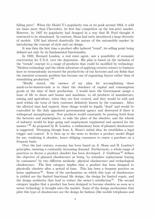
Figure 2.2.1. Number of cars produced in the world from 1999 to 2011.[Source: International Organization for Motor Manufacturers (OICA)]
multimedia players), and the design for functional enhancement through adding orupgrading product features.
2.2 Legal obsolescence trigger spiralPlanned Obsolescence is presented in vehicle design through most, if not all,
of the previously cited methods. Additionally, as proposed by B. London, vehicleindustry has been subjected to a legal obsolescence trigger. Most of the features incurrent vehicles have been bound to adapt to ever evolving norms and legislation.For example, looking at the history of the 3-point seatbelt, it was not until theSociety of Automotive Engineers (SAE) issued a standard for U.S. seat belts in1961? that slowly, state by state, and country by country, safety requirements fornew vehicles began to be established. This was 2 years after Volvo introduced thesystem in front seats as a standard in Sweden. The classic 2-point waist seat beltssystems were ruled out from the market, and manufacturers were forced to equipthemselves with the required technology for manufacturing the systems. The legaltrigger affected not only the end product but also the manufacturing technology. Thesame phenomenon can be seen with the "new" concern for vehicle manufacturers ingeneral: the ecological impact.
Moreover, the size of the car park has not ceased to increased, as shown inFig. 2.2.1. This translates onto a direct effect on polluting emissions, as the largemajority of these cars are equipped with combustion engines. In order to address thepollution problem this trend creates, legislations have been put into place. Theseaddress, amongst other things, the amount of CO2 in grams per kilometre emittedby cars. In Europe, there have been several incentives to progressively reduce theaverage CO2 emission per passenger car42.
9
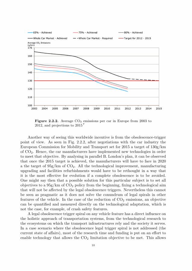
Figure 2.2.2. Average CO2 emissions per car in Europe from 2003 to2012, and projections to 2015?
Another way of seeing this worldwide incentive is from the obsolescence-triggerpoint of view. As seen in Fig. 2.2.2, after negotiations with the car industry theEuropean Commission for Mobility and Transport set for 2015 a target of 130g/kmof CO2. Hence, the car manufacturers have implemented new technologies in orderto meet that objective. By analysing in parallel B. London’s plan, it can be observedthat once the 2015 target is achieved, the manufacturers will have to face in 2020a the target of 95g/km of CO2. All the technological improvement, manufacturingupgrading and facilities refurbishments would have to be rethought in a way thatit is the most effective for evolution if a complete obsolescence is to be avoided.One might say then that a possible solution for this particular subject is to set allobjectives to a 95g/km of CO2 policy from the beginning, fixing a technological aimthat will not be affected by the legal obsolescence triggers. Nevertheless this cannotbe seen as pragmatic as it does not solve the conundrum of legal spirals in otherfeatures of the vehicle. In the case of the reduction of CO2 emissions, an objectivecan be quantified and measured directly on the technological adaptation, which isnot the case, for example, of crash safety features.
A legal obsolescence trigger spiral on any vehicle feature has a direct influence onthe holistic approach of transportation systems, from the technological research tothe ecosystems on which the transport infrastructures rely and the society it serves.In a case scenario where the obsolescence legal trigger spiral is not addressed (thecurrent state of affairs), most of the research time and funding is put on an effort toenable technology that allows the CO2 limitation objective to be met. This allows
10
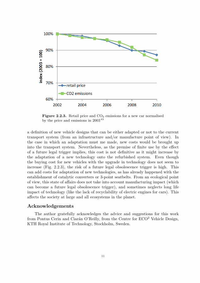
Figure 2.2.3. Retail price and CO2 emissions for a new car normalisedby the price and emissions in 200343
a definition of new vehicle designs that can be either adapted or not to the currenttransport system (from an infrastructure and/or manufacture point of view). Inthe case in which an adaptation must me made, new costs would be brought upinto the transport system. Nevertheless, as the premise of finite use by the effectof a future legal trigger implies, this cost is not definitive as it might increase bythe adaptation of a new technology onto the refurbished system. Even thoughthe buying cost for new vehicles with the upgrade in technology does not seem toincrease (Fig. 2.2.3), the risk of a future legal obsolescence trigger is high. Thiscan add costs for adaptation of new technologies, as has already happened with theestablishment of catalytic converters or 3-point seatbelts. From an ecological pointof view, this state of affairs does not take into account manufacturing impact (whichcan become a future legal obsolescence trigger), and sometimes neglects long lifeimpact of technology (like the lack of recyclability of electric engines for cars). Thisaffects the society at large and all ecosystems in the planet.
AcknowledgementsThe author gratefully acknowledges the advice and suggestions for this work
from Pontus Cerin and Ciarán O’Reilly, from the Centre for ECO2 Vehicle Design,KTH Royal Institute of Technology, Stockholm, Sweden.
11

CHAPTER 3
Tools for acoustic design of multilayered structures
This chapter presents an alternative approach to predict the acoustic response ofhomogeneous media, including anisotropic anelastic porous materials. This responseis evaluated in terms of transmission loss, but can be also assessed in terms ofreflection or absorption coefficient in a boundary condition configuration. Thismethod, together with the post-processing of the conservative and dissipative powersin the material domain, have been applied to a multilayered system including fullanisotropic properties of an open-cell foam obtained from measurements25–27. Thegoverning equations are briefly reviewed together with the expressions derived forthe computation of the individual powers in the interior of a layer as a part of themultilayer configuration. The influence of the inherent anisotropy of sound absorbingmaterials on the acoustic response and the corresponding power balances of amultilayered structure are shown. In order to illustrate the principles that controlthe acoustic behaviour, a gradual rotation of the anisotropy is investigated. In thefollowing brief summary overview of the proposed solution and the power calculationapproaches, most of the detailed mathematical considerations are omitted and maybe found in the appended publications.
3.1 Acoustic response assessment3.1.1 Formal approach
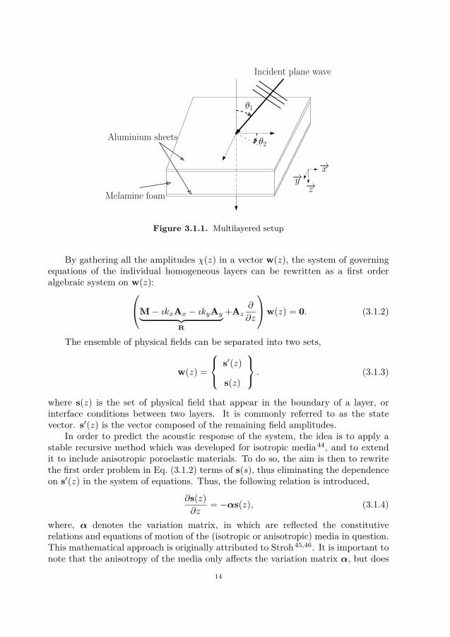
To support the discussions of the present work, a conventional multilayeredpanel is used as an example, see Fig. 3.1.1, having two isotropic, solid aluminiumface-sheets, which are attached to a single core layer of a fluid-saturated porousmelamine layer.
To model all the physical fields within each of the layers, a plane wave approachis adopted. Thus, all dependent variables may be expanded in terms of plane waves,assuming a semi-infinite configuration, and a harmonic excitation at the circularfrequency ω. The scalar physical fields χ may then be written in the following form,
χ(x, y, z, t) = χ(z)eı(ωt−kxx−kyy). (3.1.1)The cartesian coordinate system is defined in Fig. 3.1.1. The spatial dependencewith respect to x and y is common to all fields and imposed by the source. In thefollowing, this dependence is not explicitly written in order to simplify the notations.In Eq. (3.1.1), χ(z) denotes the amplitude of a generic physical field, kx and kydescribe the wavenumber of the plane wave exciting the structure.
13
θ1
−→z
−→x−→y
Melamine foam
Aluminium sheets
Incident plane wave
θ2
Figure 3.1.1. Multilayered setup
By gathering all the amplitudes χ(z) in a vector w(z), the system of governingequations of the individual homogeneous layers can be rewritten as a first orderalgebraic system on w(z):M− ıkxAx − ıkyAy︸ ︷︷ ︸
R
+Az∂
∂z
w(z) = 0. (3.1.2)
The ensemble of physical fields can be separated into two sets,
w(z) =
s′(z)
s(z)
. (3.1.3)
where s(z) is the set of physical field that appear in the boundary of a layer, orinterface conditions between two layers. It is commonly referred to as the statevector. s′(z) is the vector composed of the remaining field amplitudes.
In order to predict the acoustic response of the system, the idea is to apply astable recursive method which was developed for isotropic media44, and to extendit to include anisotropic poroelastic materials. To do so, the aim is then to rewritethe first order problem in Eq. (3.1.2) terms of s(s), thus eliminating the dependenceon s′(z) in the system of equations. Thus, the following relation is introduced,
∂s(z)∂z
= −αs(z), (3.1.4)
where, α denotes the variation matrix, in which are reflected the constitutiverelations and equations of motion of the (isotropic or anisotropic) media in question.This mathematical approach is originally attributed to Stroh45,46. It is important tonote that the anisotropy of the media only affects the variation matrix α, but does
14
not influence the interface or boundary conditions. Therefore only the derivation ofthe variation matrix is addressed.
The key idea is to express Eq. (3.1.2) is by assessing the generalised unsymmetriceigenvalue problem associated to R and Az:
Az = Rφλψ, ψ = φ−1, (3.1.5)
where λ = diagıδn, δn being the wavenumber associated with the n-th wave alongthe z direction, and φ is the matrix of eigenvectors. The eigenvalues and eigenvectorsmatrices can be reordered by the non-zero eigenvalues, subscript e, correspondingto the waves travelling along the media. An important aspect of this method relieson the fact the size of the s(z) is equal to two times the number of wave type in themedia. For example, in a fluid layer, there is only one type of wave travelling alongthe media (compressional wave, or p-wave). The size of the state vector will be then2. Thus, all the physical fields describing the fluid layer can be discretised as a sumof 2 compressional waves, travelling along both directions on the propagation axis.
By rewriting Eq. (3.1.2) on s(z), as,[Bs Bs′
] s(z)
s′(z)
= 0, (3.1.6)
then the introducing the diagonalisation in Eq. (3.1.5) and reorganisation along thetravelling waves, the most formal way of writing the variation matrix α is then,
α = − (ReφeλeψeT)−1 ReT. (3.1.7)
T is the matrix linking the state vector s(z) to the set of all the physical fieldsw(z):
w(z) =
−B−1s′ Bs
I
s(z) = Ts(z). (3.1.8)
The expression in Eq. (3.1.7) can be thusly obtained for an arbitrary media,including fully anisotropic poroelastic media. Due to the analytical nature ofthe formulation, the numerical solution can be obtained to an arbitrary degreeof accuracy. The robustness of this derivation is that numerical errors due tothe inversion of the eigenvector matrices are avoided by introducing the left andright eigenvectors successively. Additionally, analytical errors due to the manualderivations are circumvented.
3.1.2 Multilayered study caseThe general outline of the multilayered system studied is shown in Fig. 3.1.1.
The aluminium face sheets are 1mm thick each, and the porous core is 22mm thick.In order to demonstrate the influence of the anisotropy of the sound absorbing
material and its relative alignment, a study of the response for various states ofrotation of the porous material reference system has been performed. The relationsgoverning these rotations may be found in Cuenca et al.27. However, here the
15
−→x
−→z
−→yβ
β
−→x′
−→z′
Figure 3.1.2. Global coordinate system (0, x, y, z) and foam’s materialreference system (0, x′, y, z′′) as defined by rotations through the angleβ.
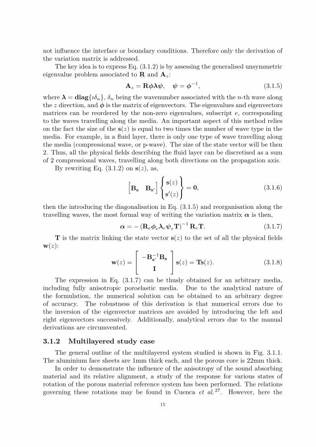
transformations are applied to rotate the foam’s material coordinate system, asopposed to rotating the global coordinate system. In the following, the angle βcorresponds to the direct rotation transformations around the (0y) axis. Thus,through the rotation, the local material coordinate system of the foam becomes(0, x′, y, z′), as seen in Fig. 3.1.2. In the unrotated state, (0, x′, y, z′) is aligned withthe global coordinate system. This multilayered configuration has been specificallychosen to induce shear deformation in the poroelastic material and include bondedinterface conditions, i.e. perfect elastic coupling between the isotropic solid facesheets and the anisotropic porous core medium.
3.1.3 ResultsAlthough the focus of the work up to this point has been set on theory
and method development to perform the investigation required, some preliminaryresults are recalled here. A comparison is made with the same multilayeredconfiguration where the poroelastic core is modelled by an equivalent isotropicmodel. This equivalent model was performed by calculating the closest isotropicequivalent according to Norris? from the anisotropic poroelastic moduli. The resultsshown illustrate the influence of material orientation and angle of incidence on thelarge-band frequency transmission loss of the overall structure.
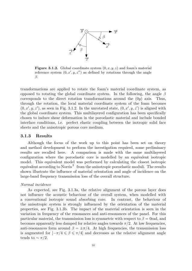
Normal incidenceAs expected, see Fig. 3.1.3a, the relative alignment of the porous layer does
not influence the acoustic behaviour of the overall system, when modelled witha conventional isotropic sound absorbing core. In contrast, the behaviour ofthe anisotropic system is strongly influenced by the orientation of the materialproperties, see Fig. 3.1.3b. The impact of the material orientation is seen in thevariation in frequency of the resonances and anti-resonances of the panel. For thisparticular material, the transmission loss is symmetric with respect to β = 0rad, andbecomes apparently less damped for relative angles towards π/2. At low frequencies,anti-resonances form around β = ±π/4. At high frequencies, the transmission lossis augmented for [−π/4 6 β 6 π/4] and decreases as the relative alignment angletends to ∼ π/2.
16
(a) Multilayered structure including closest isotropic equivalent poroelastic core
(b) Multilayered structure including anisotropic anelastic porous core
Figure 3.1.3. Acoustic transmission loss of the multilayered structureexcited by a normal incident plane wave, (θ1 = 0 deg and θ2 = 0 deg) asa function of frequency for rotations around the angle β = [−π/2;π/2]rad.
17
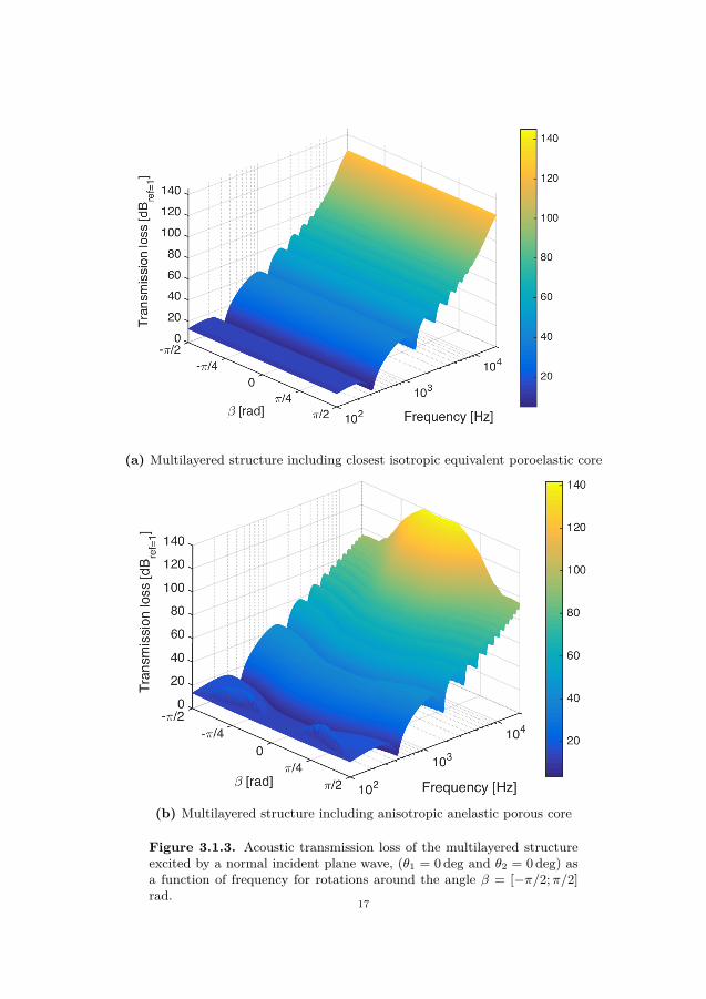
(a) θ1 = 30 deg and θ2 = 0 deg
(b) θ1 = 60 deg and θ2 = 0 deg
Figure 3.1.4. Acoustic transmission loss of the multilayered structureexcited by an oblique incident plane wave as a function of frequency forrotations around the angle β = [−π/2;π/2] rad.
18
Oblique incidenceAs the angle of incidence θ1 of the exciting plane wave increases, see Fig. 3.1.4a,
the apparent symmetry of the response with respect to β = 0 rad. is lost. Localhigh frequency anti-resonances leads to increased transmission loss of up to 20dB fornarrow frequency bands around [4− 6] kHz. The previously observed low frequencyanti-resonances are not visible anymore.
Finally, with the increase of the angle of incidence, see Fig. 3.1.4b, the overalltransmission loss decreases, in agreement with the behaviour of a system with anisotropic material core. However, the high frequency narrowband anti-resonancesare augmented, with a difference of up to ∼ 30dB between the best and worst caseresults as the material orientation is varied for a particular frequency.
3.2 Calculation of the conservative and dissipative powersAccording to the first law of thermodynamics, the following power balances hold
over a cycle, for a material domain Ω,
RPext = RPint , (3.2.1)I Pext = ıωK + I Pint , (3.2.2)
where Pext is the mean power input by external sources into the domain, Pint is themean power due to internal forces, and K is the mean of the kinetic energy in thedomain. In a dissipative domain, Pext and Pint are both complex valued quantities.It is this precise dissipative characteristic that has driven the use of highly dissipativemedia, like poroelastic materials, on multiple engineering applications.
Similar relations for the energy densities within anisotropic poroelastic mediahave been derived by Carcione et al.47,48, enabling investigations of the energypropagation in complex homogeneous media. While, the work by Carcione wasfocussed on free wave propagation applications, the contribution proposed here isaimed at the modelling of layered systems. Of particular interest is the calculationof the internal power contributions per surface area in one particular layer, requiringthe integration over a defined domain of finite thickness of the energy densities.
3.2.1 Calculation of quadratic quantitiesIn order to calculate the internal powers for multiple finite-size layers, a formal
method is presented based on the plane wave solutions previously proposed. Theintegral over a finite thickness d of a quadratic quantityW is usually expressed underthe form
W =d∫
0
f∗(z)g(z)dz. (3.2.3)
19
where f(z) and g(z) are the amplitudes of two physical fields in s(z). To calculatethe quadratic term, the state vector is discretised as a sum of waves, as such:
s(z) =2n∑k
φeke−λek
zqk = φee−λezq (3.2.4)
The vector q corresponds to the amplitudes of the waves travelling along z, φe isthe matrix of eigenvectors associated to the propagating waves within the materiallayer. Each row describes the polarisation of the corresponding wave projected oneach physical field. λe is the diagonal matrix whose kth term is equal to ıδk, whereδk is the wave number along the z direction associated with the kth wave.
Through this projection, Eq. (3.2.3) may be expressed as
W = q∗ d∫
0
e−λ∗ezΨe−λezdz
q. (3.2.5)
where Ψ contains the proper linear combination of the eigenvectors in (3.2.4). It isthis matrix that will determine the nature of the computed power or energy.
Using Eq. (3.2.5), the different power contributions may be calculated as longas the wave amplitudes q are known. These can be extracted from the projection ofthe physical fields s(z) on the basis of the waves within the media calculated at theorigin of the layer, i.e. Eq. (3.2.4) at z = 0,
q = φ−1e ζ, (3.2.6)
where ζ is a matrix easily extractable via the recursive algorithm44 that links thestate vector to the wave amplitudes.
3.2.2 ResultsOf special interest in the current work is the investigation of the partial
contribution and dissipation of energy for the deformations occurring in differentspecific directions.
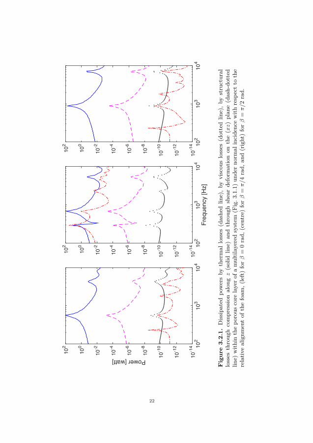
As an illustration of the potential held by the proposed methodology, the partialdissipated powers are calculated for the multilayered system illustrated in Fig. 3.1.1under a normally incident excitation. The results can be observed in Fig. 3.2.1for three different relative alignments of the porous core layer as a function offrequency. Here, the dissipated power related to thermal losses, viscous effectsand structural damping in the solid frame due to compression deformation alongthe the propagation direction, σzz, and shear deformation on the (xz) plane, σxz.The expressions for these powers can be found, in the case for an isotropic soundabsorbing material, in the literature49. These were used as the basis for thederivation of equivalent expressions for a fully anisotropic poroelastic material (seeappended publications).
It is clear that the low anti-resonance behaviour at β = π/4 rad is governedby a compression-induced shear deformation in the solid frame. This partial powerdissipation remains to be of importance over the complete frequency range studied,
20

but its contribution to the overall dissipated power becomes insignificant for relativealignments as β 7→ ±π/2 rad. It can then be observed that this compression-shearmotion coupling can influence a mechanic and acoustically performant multilayereddesign. Indeed, it has a high impact on the transmission loss of structures includinganisotropic poroelastic materials.
21
102
103
104
10-1
4
10-1
2
10-1
0
10-8
10-6
10-4
10-2
100
102
Freq
uenc
y [H
z]10
210
310
410
-14
10-1
2
10-1
0
10-8
10-6
10-4
10-2
100
102
102
103
104
Power [watt] 10-1
4
10-1
2
10-1
0
10-8
10-6
10-4
10-2
100
102
Fig
ure
3.2.
1.Dissipa
tedpo
wersby
thermal
losses
(dashe
dlin
e),by
viscou
slosses
(dottedlin
e),by
structural
losses
throug
hcompression
alon
gz(solid
line)
andthroug
hshearde
form
ationon
the
(xz)plan
e(dash-do
tted
line)
with
inthepo
rous
core
layerof
amultilayered
system
(Fig.3
.1.1)un
derno
rmal
incide
ncewith
respectto
the
relativ
ealignm
entof
thefoam
,(left)forβ
=0rad,
(centre)
forβ
=π/4rad,
and(right)forβ
=π/2rad.
22
CHAPTER 4
Conclusion & Discussion
One of the objectives of this thesis was to present the assessment of thecurrent vehicle design paradigm and its influence on ecosystems and the societyat large. The focus was the consequences of the legal obsolescence triggered by theevolution of ecological legislations. The first conclusion is that, in order to avoidlegal obsolescence triggers, vehicle engineering must shift its design methodologyin a way that the possibility of encountering a legal boundary is eluded, i.e. aproactive conceptual design process is to be adopted. This is, altogether, extremelycomplicated, as the economical implications of design paradigm changes are veryimportant. Nevertheless, it is necessary to avoid the strong influence that legalobsolescence triggers have nowadays on design choices in order to achieve an ECO2
optimal vehicle design paradigm.Furthermore, the current vehicle design paradigm requires accurate and reliable
methods for assessing the influence of real materials on the overall physical behaviourof vehicles. These methods must reflect the physics involved in the mechanical andacoustic behaviour of multilayered structures including real anisotropic media forlightweighting purposes.
Therefore, a new method for modelling the sound transmission through amultilayered structure has been proposed and discussed in detail in the appendedpapers. The methodology allows the inclusion of any homogeneous media, includinganisotropic anelastic sound absorbing materials. To further the understandingof the mechanisms triggered by the anisotropicity of the material, a method forthe computation of the acoustic power partitioning has been developed. Theevaluations of the integrals expressing the powers inside the material are calculatedby post-processing the amplitudes of the waves propagating in each layer of material.By partitioning the individual contributions to the internal power dissipation, theappearance of particular phenomena and their influence on the overall acousticresponse of the system have been investigated. It has been shown that anisotropicityhas a significant impact on the acoustic transmission response for a wide frequencyrange. As an illustrative example, a study of the orientation of the sound absorbinglayer properties vary in a multilayered configuration was performed. Rotatingthe material properties relative to the reference coordinate system affects not theresonant behaviour as compared to predictions using isotropic models, but alsothe nature of the phenomena. The presence of deformation-coupling effects in
23

anisotropic media clearly alters the dynamic behaviour of multilayered structuresand may possibly be used to tailor the performance of multifunctional designs.
24
Bibliography
[1] J. E. Diem and A. C. Comrie, “Allocating anthropogenic pollutant emissionsover space: application to ozone pollution management,” Journal ofEnvironmental Management, vol. 63, no. 4, pp. 425–447, 2001.
[2] . Poulikidou, Sofia, Integration of Design for Environment in the vehiclemanufacturing industry in Sweden : focus on practices and tools. PhD thesis,Lic.-avh. (sammanfattning) Stockholm : Kungliga Tekniska högskolan, 2013.,Stockholm, 2013.
[3] S. Poulikidou, A. Björklund, and S. Tyskeng, “Empirical study on integrationof environmental aspects into product development: processes, requirementsand the use of tools in vehicle manufacturing companies in Sweden,” Journalof Cleaner Production, vol. 81, no. 0, pp. 34–45, 2014.
[4] D. Wennberg, S. Stichel, and P. Wennhage, “Optimisation of sandwich panelsfor the load carrying structure of high-speed rail vehicles,” International Journalof Aerospace and Lightweight Structures, vol. 2, no. 1, pp. 19–40, 2012.
[5] D. Wennberg, S. Stichel, and P. Wennhage, “Substitution of corrugated sheetsin a railway vehicle’s body structure by a multiple-requirement based selectionprocess,” Proceedings of the Institution of Mechanical Engineers, Part F:Journal of Rail and Rapid Transit, vol. 228, no. 2, pp. 143–157, 2014.
[6] C. J. Cameron, P. Wennhage, P. Göransson, and S. Rahmqvist,“Structural-acoustic design of a multi-functional sandwich panel in anautomotive context,” Journal of Sandwich Structures and Materials, vol. 12,no. 6, pp. 684–708, 2010.
[7] C. J. Cameron, E. Lind Nordgren, P. Wennhage, and P. Göransson, “On thebalancing of structural and acoustic performance of a sandwich panel basedon topology, property, and size optimization,” Journal of Sound and Vibration,Mar. 2014.
[8] V. D’Alessandro, G. Petrone, F. Franco, and S. De Rosa, “A review ofthe vibroacoustics of sandwich panels: Models and experiments,” Journal ofSandwich Structures and Materials, vol. 15, no. 5, pp. 541–582, 2013.
[9] P. Göransson, “Tailored acoustic and vibrational damping in porous solids- engineering performance in aerospace applications,” Aerospace Science andTechnology, vol. 12, pp. 26–41, Jan. 2008.
[10] S. Kumar, L. Feng, and U. Orrenius, “Predicting the sound transmission loss ofhoneycomb panels using the wave propagation approach,” Acta Acustica united
25
with Acustica, vol. 97, no. 5, pp. 869–876, 2011.[11] L. Boeckx, P. Leclaire, P. Khurana, C. Glorieux, W. Lauriks, and J. F. Allard,
“Investigation of the phase velocities of guided acoustic waves in soft porouslayers,” The Journal of the Acoustical Society of America, vol. 117, no. 2,pp. 545–554, 2005.
[12] N. Geebelen, L. Boeckx, G. Vermeir, W. Lauriks, J. F. Allard, and O. Dazel,“Measurement of the rigidity coefficients of a melamine foam,” Acta Acusticaunited with Acustica, vol. 93, no. 5, pp. 783–788, 2007.
[13] b. Rayleigh, John William Strutt, The theory of sound. London: London, 1937.[14] C. Zwikker and C. Kosten, Sound absorbing materials. Elsevier, 1949.[15] M. A. Biot, “Theory of propagation of elastic waves in a fluid-saturated porous
solid. i. low-frequency range,” The Journal of the Acoustical Society of America,vol. 28, no. 2, pp. 168–178, 1956.
[16] J. F. Allard and N. Atalla, Propagation of sound in porous media. Modellingsound absorbing materials. John Wiley & Sons, 2nd edition ed., 2009.
[17] R. Lewis and B. Schrefler, The finite element method in the deformation andconsolidation of porous media. John Wiley and Sons Inc.,New York, NY, 1987.
[18] A. Gajo, A. Saetta, and R. Vitaliani, “Evaluation of three- and two-field finiteelement methods for the dynamic response of saturated soil,” InternationalJournal for Numerical Methods in Engineering, vol. 37, no. 7, pp. 1231–1247,1994.
[19] M. Östberg, P. Göransson, N.-E. Hörlin, and L. Kari, “Weak formsfor modelling of rotationally symmetric, multilayered structures, includinganisotropic poro-elastic media,” International Journal for Numerical Methodsin Engineering, vol. 90, no. 8, pp. 1035–1052, 2012.
[20] M. Melon, D. Lafarge, B. Castagnède, and N. Brown, “Measurement oftortuosity of anisotropic acoustic materials,” J. Appl. Phys., vol. 78, no. 8,pp. 4929–4932, 1995.
[21] M. Melon, E. Mariez, C. Ayrault, and S. Sahraoui, “Acoustical and mechanicalcharacterization of anisotropic open-cell foams,” The Journal of the AcousticalSociety of America, vol. 104, no. 5, pp. 2622–2627, 1998.
[22] B. Castagnède, A. Aknine, M. Melon, and C. Depollier, “Ultrasoniccharacterization of the anisotropic behavior of air-saturated porous materials,”Ultrasonics, vol. 36, no. 1-5, pp. 323–341, 1998. Ultrasonics International 1997.
[23] R. Guastavino and P. Göransson, “A 3D displacement measurementmethodology for anisotropic porous cellular foam materials,” Polym. Test.,vol. 26, pp. 711–719, Sept. 2007.
[24] R. Guastavino, Elastic and acoustic characterisation of anisotropic porousmaterials. PhD thesis, KTH, School of Engineering Sciences (SCI), Aeronauticaland Vehicle Engineering, Marcus Wallenberg Laboratory MWL, Stockholm,Sweden, 2008.
[25] J. Cuenca and P. Göransson, “Inverse estimation of the elastic and anelasticproperties of the porous frame of anisotropic open-cell foams,” J. Acoust. Soc.Am., vol. 132, no. 2, p. 621, 2012.
26
[26] C. Van der Kelen and P. Göransson, “Identification of the full anisotropicflow resistivity tensor for multiple glass wool and melamine foam samples,”J. Acoust. Soc. Am., vol. 134, p. 4659, Dec. 2013.
[27] J. Cuenca, C. Van der Kelen, and P. Göransson, “A general methodology forinverse estimation of the elastic and anelastic properties of anisotropic open-cellporous materials with application to a melamine foam,” J. Appl. Phys., vol. 115,p. 084904, Feb. 2014.
[28] J. Allard, R. Bourdier, and A. L’Esperance, “Anisotropy effect in glass woolon normal impedance in oblique incidence,” Journal of Sound and Vibration,vol. 114, no. 2, pp. 233–238, 1987.
[29] H. Rice and P. Göransson, “A dynamical model of light fibrous materials,”International Journal of Mechanical Sciences, vol. 41, no. 4-5, pp. 561–579,1999.
[30] P. Göransson and N.-E. Hörlin, “Vibro-acoustic modelling of anisotropic porouselastic materials: A preliminary study of the influence of anisotropy on thepredicted performance in a multi-layer arrangement,” Acta Acustica united withAcustica, vol. 96, no. 2, pp. 258–265, 2010.
[31] N.-E. Hörlin and P. Göransson, “Weak, anisotropic symmetric formulations ofbiot’s equations for vibro-acoustic modelling of porous elastic materials,” Int.J. Numer. Meth. Engng., vol. 84, no. 12, pp. 1519–1540, 2010.
[32] S. Finnveden, N.-E. Hörlin, and M. Barbagallo, “Dynamic characterization ofviscoelastic porous foams used in vehicles based on an inverse finite elementmethod,” The Journal of the Acoustical Society of America, vol. 135, no. 4,pp. 1834–1843, 2014.
[33] P. Khurana, L. Boeckx, W. Lauriks, P. Leclaire, O. Dazel, and J. F. Allard,“A description of transversely isotropic sound absorbing porous materials bytransfer matrices,” J. Acoust. Soc. Am., vol. 125, pp. 915–921, 2009.
[34] J. F. Allard, O. Dazel, J. Descheemaeker, N. Geebelen, L. Boeckx, andW. Lauriks, “Rayleigh waves in air saturated axisymmetrical soft porousmedia,” J. Appl. Phys., vol. 106, no. 1, pp. –, 2009.
[35] E. Lind Nordgren, P. Göransson, J.-F. Deü, and O. Dazel, “Vibroacousticresponse sensitivity due to relative alignment of two anisotropic poro-elasticlayers.,” J. Acoust. Soc. Am., vol. 133, pp. EL426–30, May 2013.
[36] A. P. Sloan, My years with General Motors. Harmondsworth, Middlesex:Penguin, 1986.
[37] A. P. O’Brien, “Struggle between ford and general motors during the 1920s and1930s,” Bus. Econ. Hist., vol. 18, no. Second Series, pp. 79–87, 1989.
[38] B. London, “Ending the depression through planned obsolescence,”self-published, 1932.
[39] J. Guiltinan, “Creative destruction and destructive creations: Environmentalethics and planned obsolescence,” Journal of Business Ethics, vol. 89, no. 1,pp. 19–28, 2009.
[40] G. Slade, Made to Break: Technology and Obsolescence in America. 2009.
27
[41] M. Woolley, “Choreographing obsolescence - ecodesign: thepleasure/dissatisfaction cycle,” pp. 77–81, 2003.
[42] L. Limousin, “Réglementation européenne sur les émissions de CO2 desvéhicules particuliers,” tech. rep., Réseau Action Climat France, 2013.
[43] J. Dings, “How clean are european cars? an analysis of carmaker progresstowards eu co2 targets in 2011,” tech. rep., European Federation for Transportand Environment (T&E), Brussels, Belgium, September 2011.
[44] O. Dazel, B. Brouard, J.-P. Groby, and P. Göransson, “A normal modestechnique to reduce the order of poroelastic models: application to 2Dand coupled 3D models,” International Journal for Numerical Methods inEngineering, vol. 96, no. 2, pp. 110–128, 2013.
[45] A. Stroh, “Steady state problems in anisotropic elasticity,” Journal ofMathematics and Physics, vol. 41, pp. 77–103, 1962.
[46] C. Baron, M. Talmant, and P. Laugier, “Effect of porosity on effective diagonalstiffness coefficients (cii) and elastic anisotropy of cortical bone at 1MHz: Afinite-difference time domain study,” The Journal of the Acoustical Society ofAmerica, vol. 122, no. 3, pp. 1810–1817, 2007.
[47] J. M. Carcione, “Energy balance and fundamental relations in dynamicanisotropic poro-viscoelasticity,” Proceedings of the Royal Society of LondonA: Mathematical, Physical and Engineering Sciences, vol. 457, no. 2006,pp. 331–348, 2001.
[48] J. M. Carcione, Wave Fields in Real Media. Burlington: Burlington Pergamon,2007.
[49] O. Dazel, F. Sgard, F.-X. Bécot, and N. Atalla, “Expressions of dissipatedpowers and stored energies in poroelastic media modeled by u,U and u,Pformulations,” The Journal of the Acoustical Society of America, vol. 123, no. 4,pp. 2054–2063, 2008.
28

Part 2
Appended publications


![CRUISE REPORT ECO2-3oceanrep.geomar.de/20580/1/ECO2-3_cruise_report.pdf · [e.g. 3,4] to geochemistry [e.g. 5,6] and microbiology [e.g. 7-9]. Driven by an increasing interest in studying](https://img.pdfslide.us/doc/110x75/5fde522260b9835ea023d570/cruise-report-eco2-eg-34-to-geochemistry-eg-56-and-microbiology-eg.jpg)