Embed Size (px)
Citation preview

ManualManualManualManualManual M 19M 19M 19M 19M 19Issue 02.0202.0202.0202.0202.02Supersedes - - -- - -- - -- - -- - -
OMEGA.V 2001188 ÷ 1143 kW
Operating,Operating,Operating,Operating,Operating,installationinstallationinstallationinstallationinstallationand maintenance manualand maintenance manualand maintenance manualand maintenance manualand maintenance manual
Water/Water chillersWater/Water chillersWater/Water chillersWater/Water chillersWater/Water chillers
Semihermetic screw compressorsSemihermetic screw compressorsSemihermetic screw compressorsSemihermetic screw compressorsSemihermetic screw compressors


i
INDEXINDEXINDEXINDEXINDEX Pag.Pag.Pag.Pag.Pag.
OMEGA V 2001 - Water chiller ............................................................................................. 1TECHNICAL CHARACTERISTICS ........................................................................................... 1
UNIT FRAME .................................................................................................................... 1COMPRESSORS ................................................................................................................ 1HEAT EXCHANGERS......................................................................................................... 1REFRIGERANT CIRCUIT ..................................................................................................... 1ELECTRICAL PANEL .......................................................................................................... 1CONTROL AND SAFETY DEVICES ..................................................................................... 1TESTS ............................................................................................................................... 1
OTHER VERSIONS ................................................................................................................ 2OMEGA V 2001 /DC: unit with heat recovery condenser .................................................... 2OMEGA V 2001 /LC: motoevaporating unit ....................................................................... 2OMEGA V 2001 /LN: low noise unit ................................................................................... 2
ACCESSORIES: .................................................................................................................... 2
THE SERIES .......................................................................................................................... 3
TECHNICAL DATA ............................................................................................................... 4CHARACTERISTICS AND ELECTRICAL DATA ........................................................................ 4SOUND POWER AND PRESSURE LEVEL ................................................................................ 8
1. SAFETY REQUIREMENTS ........................................................................................................................................................................................................................................... 9
1.1 DANGEROUS AREA ............................................................................................................. 91.2 SAFETY ............................................................................................................................... 9
MECHANICAL SAFETY DATA ........................................................................................... 10THERMAL SAFETY DATA .................................................................................................. 10NOISE SAFETY DATA........................................................................................................ 11ELECTRICAL SAFETY DATA .............................................................................................. 11REFRIGERANT SAFETY DATA - R407C ............................................................................... 12
2. APPLICATION FIELD ............................................................................................................. 142.1 GENERALITY ........................................................................................................................ 14
3. INSPECTION, TRANSPORT, SITE HANDLING ......................................................................... 143.1 INSPECTION ........................................................................................................................ 143.2 LIFTING AND TRANSPORT .................................................................................................... 143.3 UNPACKING ........................................................................................................................ 153.4 LOCATION ........................................................................................................................... 15
4. INSTALLATION ..................................................................................................................... 164.1 CLEARANCES ...................................................................................................................... 164.2 GENERAL RECOMMENDATIONS FOR WATER PIPING CONNECTIONS ................................... 164.3 WATER PIPE CONNECTIONS TO EVAPORATOR .................................................................... 184.4 FLEXIBLE JOINTS .................................................................................................................. 194.5 WATER PIPE CONNECTION TO THE CONDENSER ................................................................. 204.6 DESUPERHEATER HYDRAULIC CONNECTIONS (optional) ..................................................... 214.7 HEAT RECOVERY EXCHANGE HYDRAULIC CONNECTIONS (Version /DC) ............................. 214.8 REMOTE AIR COOLED CONDENSER CONNECTION (VERSION LC) ......................................... 234.8.1 Refrigerant connections ..................................................................................................... 234.8.2 Pipings layout and max distance between the 2 sections .................................................... 234.8.3 Recomendations for installation of the refrigerant line ........................................................ 254.8.4 Version LC: remote condenser above the evaporating unit: ................................................ 254.8.5 Version LC: remote air cooled condenser below the evaporating unit: .................................. 264.9 SAFETY VALVES RELIEF ....................................................................................................... 26

ii
4.10 WATER QUALITY ................................................................................................................ 264.11 LOW TEMPERATURE WATER AT CONDENSER ..................................................................... 274.12 OPERATION WITH LOW TEMPERATURE CHILLED WATER AT EVAPORATOR ......................... 27
OPERATION LIMITS ........................................................................................................... 284.13 CONDENSER AND EVAPORATOR WATER FLOW RATE .......................................................... 294.14 CHILLED WATER Temperature TO THE EVAPORATOR .......................................................... 294.15 ELECTRICAL CONNECTIONS ................................................................................................ 314.15.1 Generality ......................................................................................................................... 314.15.2 Potential free contacts ...................................................................................................... 334.15.3 Circulating pump electrical connections ............................................................................. 334.15.4 Microprocessor controller on the unit ................................................................................. 334.15.5 Serial RS485 interface (opzion) .......................................................................................... 334.15.6 User interface – Microprocessor pCO2 ................................................................................ 34
5. START UP ............................................................................................................................ 365.1 PRELIMINARY CHECKS ........................................................................................................ 365.2 WORKING DESCRIPTION ...................................................................................................... 365.2.1 General ............................................................................................................................ 365.2.2 Unit in stand-by mode ....................................................................................................... 365.2.3 Enabling the unit .............................................................................................................. 375.2.4 Pumps control ................................................................................................................... 375.2.5 Compressors start-up ......................................................................................................... 375.2.6 Chiller operation ............................................................................................................... 375.2.7 Evaporator antifrost ........................................................................................................... 375.2.8 Antifrost heater (opzion).................................................................................................... 375.2.9 Working of compressors .................................................................................................... 375.2.10 High and low pressure alarms ........................................................................................... 385.2.11 Compressor and step capacity control ................................................................................ 385.2.12 Desuperheater (option) .................................................................................................... 395.2.13 Heat recovery (OMEGA V 2001/DC only) .......................................................................... 395.2.14 Dual set point (option) ...................................................................................................... 395.2.15 Operation with outlet water temperature (option) .............................................................. 395.3 COMMISSIONING ................................................................................................................ 405.4 CONTROLS DURING UNIT OPERATION ................................................................................. 405.5 REFRIGERANT CHARGE CHECK ........................................................................................... 405.6 SHUTTING DOWN THE UNIT ................................................................................................ 415.7 EMERGENCY SHUTDOWN ................................................................................................... 41
6. CONTROL DEVICES SETTING VALUES .................................................................................. 426.1 GENERALITY ........................................................................................................................ 42
7. MAINTENANCE AND PERIODIC CHECKS ............................................................................. 437.1 IMPORTANT RULES .............................................................................................................. 437.2 GENERALITY ........................................................................................................................ 437.3 REFRIGERANT CIRCUIT REPAIR ............................................................................................. 447.3.1 Refrigerant leakage check ................................................................................................. 447.3.2 Vacuum and drying of refrigerant circuit ............................................................................ 447.3.3 Refrigerant charge ............................................................................................................ 457.4 ENVIRONMENT PROTECTION ............................................................................................... 45
8. PUTTING THE UNIT OUT OF SERVICE ................................................................................... 46
9. TROUBLE SHOOTING ........................................................................................................... 46
OVERALL DIMENSIONS AND HYDRAULIC CONNECTIONS .................................................... 53
REFRIGERANT CIRCUIT DIAGRAM ........................................................................................ 57REFRIGERANT CIRCUIT DIAGRAM /LC .................................................................................. 58REFRIGERANT CIRCUIT DIAGRAM / LC DC ........................................................................... 59

Blue Box Pag. 1
OMEGA V 2001 - Water chillerOMEGA V 2001 - Water chillerOMEGA V 2001 - Water chillerOMEGA V 2001 - Water chillerOMEGA V 2001 - Water chiller
Water cooled water chiller with semihermetic compressor, shell and tube heat exchangers. Unit is suitable forindoor insatllation.
TECHNICAL CHARACTERISTICSTECHNICAL CHARACTERISTICSTECHNICAL CHARACTERISTICSTECHNICAL CHARACTERISTICSTECHNICAL CHARACTERISTICS
UNIT FRAMEUNIT FRAMEUNIT FRAMEUNIT FRAMEUNIT FRAMESelf-supporting frame made from galvanised steel protected with polyester powder paint enamel (stoved at180°). Stainless steel screws and bolts.
COMPRESSORSCOMPRESSORSCOMPRESSORSCOMPRESSORSCOMPRESSORSscrew-type semi-hermetic compressor, direct male rotor/female rotor drive, with crankcase heater. Lubrificationensured by delivery and intake pressure difference. Continuous cooling capacity control available, enabling tomaximise the energetic efficiency of the unit in any working condition. Integral electronic motor protection andtemperature sensors inserted directly in windings. Delta-star motor start-up and standard capacity step reduction.
HEAT EXCHANGERSHEAT EXCHANGERSHEAT EXCHANGERSHEAT EXCHANGERSHEAT EXCHANGERSshell and tube type, dry expansion evaporator. Insulation with closed-cell foam material for reduced heat loss.All evaporators are fitted with temperature probe for anti-freeze protection.
REFRIGERANT CIRCUITREFRIGERANT CIRCUITREFRIGERANT CIRCUITREFRIGERANT CIRCUITREFRIGERANT CIRCUITIncludes: compressor delivery valves, liquid line shut-off valve, charging connection, liquid sight glass, drier filter,thermostatic valve, high and low pressure, evaporation and condensation temperature probes for readout bycontrol.
ELECTRICAL PANELELECTRICAL PANELELECTRICAL PANELELECTRICAL PANELELECTRICAL PANELThe electric panel includes:- main switch- power and auxiliary cicuits fuses- compressor contactors- microprocessor for control of the following functions:
- water temperature control- anti-freeze protection- compressor operation timing- compressor automatic start-up sequence- alarm signals- alarm reset- potential contact for remote alarm signals
- digital display of:- inlet and outlet water temperature- temperature and differential settings- alarm description- hour meters readout of operation and number of unit, compressor start-ups- high and low pressures, relative condensation and evaporation temperature controls.
Electri power supply [V/f/Hz]: 400/3~/50 ±5%
CONTROL AND SAFETY DEVICESCONTROL AND SAFETY DEVICESCONTROL AND SAFETY DEVICESCONTROL AND SAFETY DEVICESCONTROL AND SAFETY DEVICES- manual-reset high pressure switch- manual high / low pressure switch controlled by microprocessor- mechanical flow switch- compressors over temperature protection on supply gas with liquid injection
TESTSTESTSTESTSTESTSTESTSUnits are factory tested and come with oil and refrigerant fluid charges.

Blue Box Pag. 2
OTHER VERSIONSOTHER VERSIONSOTHER VERSIONSOTHER VERSIONSOTHER VERSIONS
OMEGA V 2001 /DC: OMEGA V 2001 /DC: OMEGA V 2001 /DC: OMEGA V 2001 /DC: OMEGA V 2001 /DC: unit with heat recovery condenserunit with heat recovery condenserunit with heat recovery condenserunit with heat recovery condenserunit with heat recovery condenserBesides the standard components of the OMEGA V 2001 for each compressor the unit includes a 100% heatrecovery condenser for hot water production. The recovery water temperature control and the safety heat recoverydisabling are automatically handled by the microprocessor.
OMEGA V 2001 /LC: motoevaporating unitOMEGA V 2001 /LC: motoevaporating unitOMEGA V 2001 /LC: motoevaporating unitOMEGA V 2001 /LC: motoevaporating unitOMEGA V 2001 /LC: motoevaporating unitThe unit is manufactured without water condenser, to be connected to a remore air coole dondenser.
OMEGA V 2001 /LN: low noise unitOMEGA V 2001 /LN: low noise unitOMEGA V 2001 /LN: low noise unitOMEGA V 2001 /LN: low noise unitOMEGA V 2001 /LN: low noise unitBesides the standard components of the OMEGA V 2001 version, the unit includes:- compressors fitted in soundproofed compartment made of painted galvanized sheet with internal insulation,
sound-absorbing mat with high impedance material inserted.- compressor on antivibrating mountings.
ACCESSORIES:ACCESSORIES:ACCESSORIES:ACCESSORIES:ACCESSORIES:- Desuperheaters- Additional compressor step control- Rubber or spring vibration dampers- Pressostatic valve- Mechanical flow switch- Continuous compressor step control- Electronic expansion valve- Solenoid valve on liquid line- Liquid receiver- Compressor suction valve- Power factor cos ϕ ≥ 0.9 at nominal working conditions- Single potential free contacts- Serial interface- Double set point- Remote contro terminal (added to the standard one)- Variable Set point with remote signal- Leaving water temperature control
Standard units Low noise units
Picture 1Picture 1Picture 1Picture 1Picture 1

Blue Box Pag. 3
THE SERIESTHE SERIESTHE SERIESTHE SERIESTHE SERIES
Water cooled water chillers OMEGA.V 2001 are available in various sizes with capacities ranging from 187 to1153 kW.
The model can be identified by two numbers:
OMEGA V 2001 71.2 OMEGA V 2001 71.2 OMEGA V 2001 71.2 OMEGA V 2001 71.2 OMEGA V 2001 71.2
Nominal cooling capacity* in kW x 10 number of circuits
* Capacity refers to water inlet/outlet 12/7 °C, condenser water temperature 30/35 °C.
Model, factory number, technical data, electric power supply, etc. are reported on the labels of the unit.

Blue Box Pag. 4
CHARACTERISTICS AND ELECTRICAL DATACHARACTERISTICS AND ELECTRICAL DATACHARACTERISTICS AND ELECTRICAL DATACHARACTERISTICS AND ELECTRICAL DATACHARACTERISTICS AND ELECTRICAL DATA
(*) evaporator entering/leaving water temperature 12-7 °C condenser entering/leaving water temperature 30-35 °C(**) Valid only for standard units
TECHNICAL DATATECHNICAL DATATECHNICAL DATATECHNICAL DATATECHNICAL DATA Refrigerant R407CRefrigerant R407CRefrigerant R407CRefrigerant R407CRefrigerant R407C
(1) Electric power supply which must be available from the net
(2) Current of intervention of the internal protections of unit. It is the max absorbed current of unit. This value isnever exceeded and must be utilized to dimension the line supply and the protections (see el. diagram of unit).
MO DEL OMEGA V 2001 19.1 22.1 27.1 33.1 38.2 39.1Maximum absorbed power (1) kW 70,3 81,3 98,1 116,9 140,6 130,9Maximum starting current A 155 188 240 263 279 323Full load current (2) A 124 140 168 196 248 225Power supply V/f/HzControl power supply V/f/Hz
400/3~/50 ±5%230/~/50
������������
����
����
��������
����
��������
������������
����������������������������������������������������������������������������������������������������������������������������������������������������������������������������������������������������������������������������������������������������������������������������������������������������������������������������������������������������������������������������������������������������������������������������������������������������������������������������������������������������������������������������������������������������������������������������������������������������������������������������������������������������������������������������������������������������������������������������������������������������������������������������������������������������������������������������������������������������������������������������������������������������������������������������
MODEL OMEGA V 2001 19.1 22.1 27.1 33.1 38.2 39.1Coo l ing (*)
Nominal capacity kW 188 217,4 270 322,4 376,1 380,2
Evaporator water flow l/s 8,985 10,387 12,899 15,405 17,969 18,164(l/h) 32.344 37.393 46.436 55.458 64.688 65.391
Evaporator pressure drop kPa 71,2 20,6 26,6 37,4 58,8 59,9Condenser water flow l/s 11,322 13,09 16,159 19,336 22,644 22,565
(l/h) 40.760 47.124 58.173 69.609 81.519 81.233Condenser pressure drop kPa 12,8 13,8 16,9 17,3 12,8 17,7Compressors typeQuantity n 1 1 1 1 2 1Absorbed power cooling (*) kW 48,9 56,6 68,2 82,3 97,9 92,1Capacity steps % 0-50-100 0-50-100 0-50-100 0-50-100 0-25-50- 0-50-100
75-100Refr igerant chargeCircuit C1 kg 25 26 27 50 25 54Circuit C2 kg --- --- --- --- 25 ---O i lCircuit C1 l 10 10 11 11 10 15Circuit C2 l --- --- --- --- 10 ---Oil producerOil type
Evaporator typeEvaporator water volume l 54,8 112 105 96,2 159,6 159,6Max operating pressure water side barCondenser typeCondenser 1 water volume l 18,3 20,2 22,1 29 18,3 32,8Condenser 2 water volume l --- --- --- --- 18,3 ---Max operating pressure water side barDimension and weight (** )Length mm 2.885 3.410 3.430 3.445 3.450 3.480Width mm 1.500 1.500 1.500 1.500 1.500 1.500Heigth mm 1.610 1.610 1.610 1.690 2.015 1.690Shipping weight kg 1.138 1.297 1.423 1.553 2.197 1.800
10
semihermetic screw
shell and tube
DEASE 170
shell and tube
10
��������������������
��������������������
����������
����������
����������
����������
������������
������������
��������������
������
������
������
������
��������
������
��������
����
����
����
����
������
������������
��������������
����
����
����
����
����
��������
��������
��
��
��
��
��
����������
����������
���
���
���
���
���
��������������
�������
�������
�������
�������
�������
��������������
��������������������������������������������������������������������������������������������������������������������������������������������������������������������������������������������������������������������������������������������
��������������������������������������������������������������������������������������������������������������������������������������������������������������������������������������������������������������������������������������������
��������������������������������������������������������������������������������������������������������������������������������������������
����������������������������������������������������������������������������������������������������������������������������������������������������������������������������������������������������������������������������������������������������������������������������������������
����������������������������������������������������������������������������������������������������������������������������������������������������������������������������������������������������������������������������������������������������������������������������������������
��������������������������������������������������������������������������������������������������������������������������������������������
��������������������������������������������������������������������������������������������������������������������������������������������

Blue Box Pag. 5
CHARACTERISTICS AND ELECTRICAL DATACHARACTERISTICS AND ELECTRICAL DATACHARACTERISTICS AND ELECTRICAL DATACHARACTERISTICS AND ELECTRICAL DATACHARACTERISTICS AND ELECTRICAL DATA
TECHNICAL DATATECHNICAL DATATECHNICAL DATATECHNICAL DATATECHNICAL DATA Refrigerant R407CRefrigerant R407CRefrigerant R407CRefrigerant R407CRefrigerant R407C
(1) Electric power supply which must be available from the net
(2) Current of intervention of the internal protections of unit. It is the max absorbed current of unit. This value isnever exceeded and must be utilized to dimension the line supply and the protections (see el. diagram of unit).
(*) evaporator entering/leaving water temperature 12-7 °C condenser entering/leaving water temperature 30-35 °C(**) Valid only for standard units
MO DEL OMEGA V 2001 43.1 44.2 47.1 52.1 54.2 58.1Maximum absorbed power (1) kW 145 162,6 157,3 175,1 196,2 195Maximum starting current A 374 328 453 543 408 595Full load current (2) A 245 280 270 300 336 334Power supply V/f/HzControl power supply V/f/Hz
400/3~/50 ±5%230/~/50
������
��������
����
����
��������
����
������
����������������������������������������������������������������������������������������������������������������������������������������������������������������������������������������������������������������������������������������������������������������������������������������������������������������������������������������������������������������������������������������������������������������������������������������������������������������������������������������������������������������������������������������������������������������������������������������������������������������������������������������������������������������������������������������������������������������������������������������������������������������������������������������������������������������������������������������������������������������������������������������������������������������������������
MODEL OMEGA V 2001 43.1 44.2 47.1 52.1 54.2 58.1Coo l ing (*)
Nominal capacity kW 424,8 434,8 460,2 517,5 540 571,5
Evaporator water flow l/s 20,296 20,774 21,987 24,724 25,798 27,306l/h 73.065 74.786 79.153 89.006 92.872 98.303
Evaporator pressure drop kPa 53 55,3 62,7 57,7 42,8 47,4Condenser water flow l/s 25,17 26,18 27,276 30,806 32,318 34,15
(l/h) 90.612 94.248 98.195 110.902 116.346 122.941Condenser pressure drop kPa 17,2 13,8 16,2 16 16,9 15,1Compres sors typeQuantity n 1 2 1 1 2 1Absorbed power cooling (*) kW 102 113,1 110,7 127,3 136,5 143,2Capacity steps % 0-50-100 0-25-50- 0-50-100 0-50-100 0-25-50- 0-50-100
75-100 75-100Refr igerant chargeCircuit C1 kg 53 25 55 60 29 79Circuit C2 kg --- 25 --- --- 29 ---O i lCircuit C1 l 15 10 18 18 11 18Circuit C2 l --- 10 --- --- 11 ---Oil producerOil type
Evaporator typeEvaporator water volume l 150 150 136,2 266 247,8 247,8Max operating pressure water side barCondenser typeCondenser 1 water volume l 36,5 20,2 40,3 31,4 22,1 51,6Condenser 2 water volume l --- 20,2 --- --- 22,1 ---Max operating pressure water side barDimension and weight (** )Length mm 3.480 3.450 3.480 3.500 3.535 3.520Width mm 1.500 1.500 1.500 1.500 1.500 1.500Heigth mm 1.690 2.015 1.690 1.690 2.095 1.740Shipping weight kg 1.850 2.267 2.169 2.410 2.742 2.559
semihermetic screw
DEASE 170
shell and tube
shell and tube
10
10
������������������
���������
������������������
���������
������������������
������������������
������������������
������������
������
����������
�����
����������
����������
������������
������
����
��������
����
��������
��������
����������
������������
�������
����������
�����
����������
����������
����������
��������
����
����
��
����
����
����
������������
������
��������
����
��������
��������
��������
������
������������
������
������������
������������
������������
������������
��������������������������������������������������������������������������������������������������������������������������������������������������������������������������������������������������������������������������������������������
��������������������������������������������������������������������������������������������������������������������������������������������������������������������������������������������������������������������������������������������
��������������������������������������������������������������������������������������������������������������������������������������������
����������������������������������������������������������������������������������������������������������������������������������������������������������������������������������������������������������������������������������������������������������������������������������������
����������������������������������������������������������������������������������������������������������������������������������������������������������������������������������������������������������������������������������������������������������������������������������������
��������������������������������������������������������������������������������������������������������������������������������������������
����������������������������������������������������������������������������������������������������������������������������������������������������������������������������������������������������������������������������������������������������������������������������������������

Blue Box Pag. 6
TECHNICAL DATATECHNICAL DATATECHNICAL DATATECHNICAL DATATECHNICAL DATA Refrigerant R407CRefrigerant R407CRefrigerant R407CRefrigerant R407CRefrigerant R407C
CHARACTERISTICS AND ELECTRICAL DATACHARACTERISTICS AND ELECTRICAL DATACHARACTERISTICS AND ELECTRICAL DATACHARACTERISTICS AND ELECTRICAL DATACHARACTERISTICS AND ELECTRICAL DATA
(*) evaporator entering/leaving water temperature 12-7 °C condenser entering/leaving water temperature 30-35 °C(**) Valid only for standard units
(1) Electric power supply which must be available from the net
(2) Current of intervention of the internal protections of unit. It is the max absorbed current of unit. This value isnever exceeded and must be utilized to dimension the line supply and the protections (see el. diagram of unit).
MO DEL OMEGA V 2001 60.2 65.2 71.2 77.2 82.2 86.2Maximum absorbed power (1) kW 215 233,8 247,8 261,8 275,9 290Maximum starting current A 436 459 488 548 568 619Full load current (2) A 364 392 421 450 470 490Power supply V/f/HzControl power supply V/f/Hz
400/3~/50 ±5%230/~/50
������������
����
����
��������
����
��������
������������
����������������������������������������������������������������������������������������������������������������������������������������������������������������������������������������������������������������������������������������������������������������������������������������������������������������������������������������������������������������������������������������������������������������������������������������������������������������������������������������������������������������������������������������������������������������������������������������������������������������������������������������������������������������������������������������������������������������������������������������������������������������������������������������������������������������������������������������������������������������������������������������������������������������������������
MODEL OMEGA V 2001 60.2 65.2 71.2 77.2 82.2 86.2Coo l ing (*)
Nominal capacity kW 593,2 644,9 702,6 760,4 805 849,6Evaporator water flow l/s 28,34 30,81 33,569 36,329 38,46 40,592
l/h 102.022 110.916 120.850 130.783 138.457 146.131Evaporator pressure drop kPa 50,7 55 46,6 53,7 36,1 39,8Condenser water flow l/s 35,519 38,672 41,901 45,13 47,735 50,34
(l/h) 127.870 139.219 150.843 162.467 171.846 181.225Condenser pressure drop kPa 20,1 17,3 20 17,7 19,5 17,2Compressors typeQuantity n 2 2 2 2 2 2Absorbed power cooling (*) kW 150,3 164,5 174,4 184,2 194,1 204Capacity steps % 0-25-50- 0-25-50- 0-25-50- 0-25-50- 0-25-50- 0-25-50-
75-100 75-100 75-100 75-100 75-100 75-100Refr igerant chargeCircuit C1 kg 52 52 54 55 58 55Circuit C2 kg 29 52 54 55 55 55Oi lCircuit C1 l 11 11 15 15 15 15Circuit C2 l 11 11 11 15 15 15Oil producerOil typeEvaporator typeEvaporator water volume l 247,8 184,4 225 225 403 403Max operating pressure water side barCondenser typeCondenser 1 water volume l 22,1 29 29 32,8 32,8 36,5Condenser 2 water volume l 22,1 29 29 32,8 32,8 36,5Max operating pressure water side barDimension and weight (** )Length mm 3.535 3.365 3.860 3.860 3.895 3.895Width mm 1.500 1.500 1.500 1.500 1.500 1.500Heigth mm 2.095 2.095 2.095 2.095 2.195 2.165Shipping weight kg 2.868 2.945 3.185 3.333 3.622 3.640
semihermetic screw
DEASE 170
shell and tube
shell and tube
10
10
��������������������
��������������������
����������
����������
����������
����������
������������
����������
������������
�����
�����
�����
�����
�������
������
��������
����
����
����
����
����
������������
������������
����
����
����
����
����
��������
��������
��
��
��
��
��
������������
������������
����
����
����
����
����
������������
������
������
������
������
������
������������
��������������������������������������������������������������������������������������������������������������������������������������������������������������������������������������������������������������������������������������������
��������������������������������������������������������������������������������������������������������������������������������������������������������������������������������������������������������������������������������������������
��������������������������������������������������������������������������������������������������������������������������������������������
����������������������������������������������������������������������������������������������������������������������������������������������������������������������������������������������������������������������������������������������������������������������������������������
����������������������������������������������������������������������������������������������������������������������������������������������������������������������������������������������������������������������������������������������������������������������������������������
��������������������������������������������������������������������������������������������������������������������������������������������
��������������������������������������������������������������������������������������������������������������������������������������������

Blue Box Pag. 7
TECHNICAL DATATECHNICAL DATATECHNICAL DATATECHNICAL DATATECHNICAL DATA Refrigerant R407CRefrigerant R407CRefrigerant R407CRefrigerant R407CRefrigerant R407C
CHARACTERISTICS AND ELECTRICAL DATACHARACTERISTICS AND ELECTRICAL DATACHARACTERISTICS AND ELECTRICAL DATACHARACTERISTICS AND ELECTRICAL DATACHARACTERISTICS AND ELECTRICAL DATA
(*) evaporator entering/leaving water temperature 12-7 °C condenser entering/leaving water temperature 30-35 °C(**) Valid only for standard units
(1) Electric power supply which must be available from the net
(2) Current of intervention of the internal protections of unit. It is the max absorbed current of unit. This value isnever exceeded and must be utilized to dimension the line supply and the protections (see el. diagram of unit).
MO DEL OMEGA V 2001 90.2 93.2 104.2 116.2Maximum absorbed power (1) kW 302,3 314,6 350,2 390Maximum starting current A 644 723 843 929Full load current (2) A 515 540 600 668Power supply V/f/HzControl power supply V/f/Hz
400/3~/50 ±5%230/~/50
������
��������
����
��������
������������
����������������������������������������������������������������������������������������������������������������������������������������������������������������������������������������������������������������������������������������������������������������������������������������������������������������������������������������������������������������������������������������������������������������������������������������������������������������������������������������������������������������������������������������������������������������������������������������������������������������������������������������������������������������������������������������������������������������������������������������
MODEL OMEGA V 2001 90.2 93.2 104.2 116.2Coo l ing (*)
Nominal capacity kW 891,1 920,4 1035 1143,1Evaporator water flow l/s 42,573 43,974 49,448 54,613
l/h 153.263 158.307 178.013 196.606Evaporator pressure drop kPa 43,4 46 57,3 82,7Condenser water flow l/s 52,649 54,553 61,612 68,301
(l/h) 189.537 196.391 221.804 245.882Condenser pressure drop kPa 18,6 16,2 16 15,1Compressors typeQuantity n 2 2 2 2Absorbed power cooling (*) kW 210,9 221,4 254,6 286,5Capacity steps % 0-25-50- 0-25-50- 0-25-50- 0-25-50-
75-100 75-100 75-100 75-100Refr igerant chargeCircuit C1 kg 55 54 64 82Circuit C2 kg 54 54 64 82Oi lCircuit C1 l 18 18 18 18Circuit C2 l 15 18 18 18Oil producerOil type
Evaporator typeEvaporator water volume l 403 403 378 348Max operating pressure water side barCondenser typeCondenser 1 water volume l 36,5 40,3 31,4 51,6Condenser 2 water volume l 36,5 40,3 31,4 51,6Max operating pressure water side barDimension and weight (** )Length mm 4.025 4.040 4.040 4.040Width mm 1.500 1.500 1.500 1.500Heigth mm 2.220 2.220 2.220 2.270Shipping weight kg 3.933 4.222 4.385 4.612
10
10
semihermetic screw
shell and tube
shell and tube
DEASE 170
��������������������
����������
��������������������
����������
����������������������
������������
�������
������������
������
��������������
������
����
��������
����
����������
����������
������
��������
����
��������
����������
�����
����
��
����
����������
�����
������
���
������
�������
��������������
�������
��������������
��������������
��������������������������������������������������������������������������������������������������������������������������������������������������������������������������������������������
��������������������������������������������������������������������������������������������������������������������������������������������������������������������������������������������
��������������������������������������������������������������������������������������������
����������������������������������������������������������������������������������������������������������������������������������������������������������������������������������������
������������������������������������������������������������������������������������������������������������������������������������������������������������������������������������������������������������������������������������������������������������������������������������
��������������������������������������������������������������������������������������������
��������������������������������������������������������������������������������������������
Blue Box Pag. 8
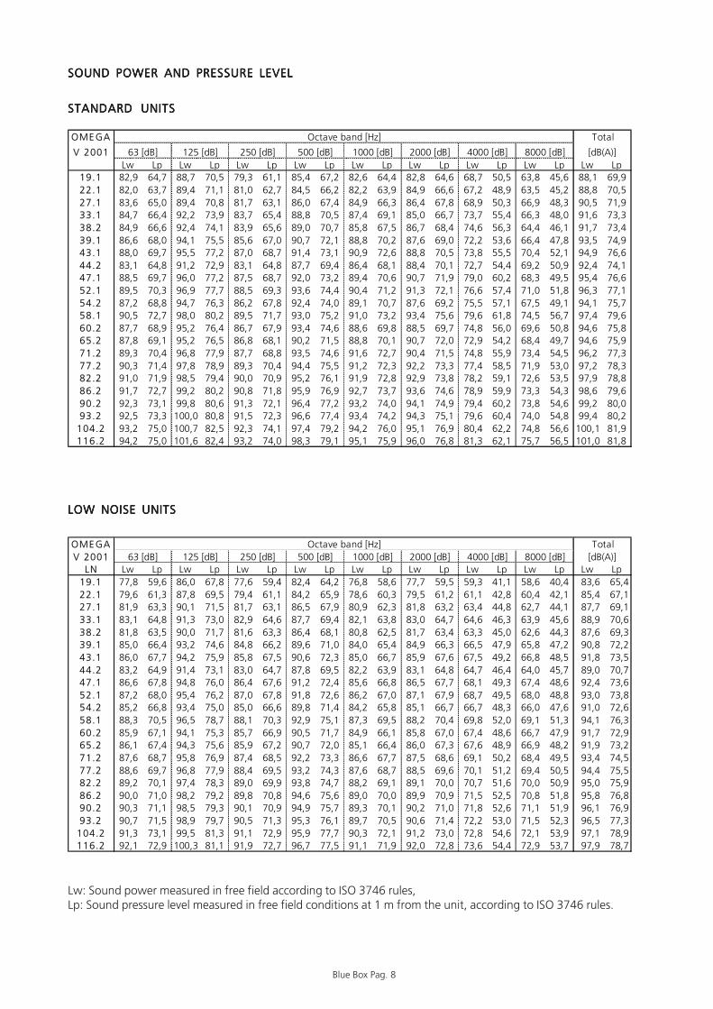
SOUND POWER AND PRESSURE LEVELSOUND POWER AND PRESSURE LEVELSOUND POWER AND PRESSURE LEVELSOUND POWER AND PRESSURE LEVELSOUND POWER AND PRESSURE LEVEL
STANDARD UNITSSTANDARD UNITSSTANDARD UNITSSTANDARD UNITSSTANDARD UNITS
LOW NOISE UNITSLOW NOISE UNITSLOW NOISE UNITSLOW NOISE UNITSLOW NOISE UNITS
OME GA
V 2001Lw Lp Lw Lp Lw Lp Lw Lp Lw Lp Lw Lp Lw Lp Lw Lp Lw Lp
19.1 82,9 64,7 88,7 70,5 79,3 61,1 85,4 67,2 82,6 64,4 82,8 64,6 68,7 50,5 63,8 45,6 88,1 69,922.1 82,0 63,7 89,4 71,1 81,0 62,7 84,5 66,2 82,2 63,9 84,9 66,6 67,2 48,9 63,5 45,2 88,8 70,527.1 83,6 65,0 89,4 70,8 81,7 63,1 86,0 67,4 84,9 66,3 86,4 67,8 68,9 50,3 66,9 48,3 90,5 71,933.1 84,7 66,4 92,2 73,9 83,7 65,4 88,8 70,5 87,4 69,1 85,0 66,7 73,7 55,4 66,3 48,0 91,6 73,338.2 84,9 66,6 92,4 74,1 83,9 65,6 89,0 70,7 85,8 67,5 86,7 68,4 74,6 56,3 64,4 46,1 91,7 73,439.1 86,6 68,0 94,1 75,5 85,6 67,0 90,7 72,1 88,8 70,2 87,6 69,0 72,2 53,6 66,4 47,8 93,5 74,943.1 88,0 69,7 95,5 77,2 87,0 68,7 91,4 73,1 90,9 72,6 88,8 70,5 73,8 55,5 70,4 52,1 94,9 76,644.2 83,1 64,8 91,2 72,9 83,1 64,8 87,7 69,4 86,4 68,1 88,4 70,1 72,7 54,4 69,2 50,9 92,4 74,147.1 88,5 69,7 96,0 77,2 87,5 68,7 92,0 73,2 89,4 70,6 90,7 71,9 79,0 60,2 68,3 49,5 95,4 76,652.1 89,5 70,3 96,9 77,7 88,5 69,3 93,6 74,4 90,4 71,2 91,3 72,1 76,6 57,4 71,0 51,8 96,3 77,154.2 87,2 68,8 94,7 76,3 86,2 67,8 92,4 74,0 89,1 70,7 87,6 69,2 75,5 57,1 67,5 49,1 94,1 75,758.1 90,5 72,7 98,0 80,2 89,5 71,7 93,0 75,2 91,0 73,2 93,4 75,6 79,6 61,8 74,5 56,7 97,4 79,660.2 87,7 68,9 95,2 76,4 86,7 67,9 93,4 74,6 88,6 69,8 88,5 69,7 74,8 56,0 69,6 50,8 94,6 75,865.2 87,8 69,1 95,2 76,5 86,8 68,1 90,2 71,5 88,8 70,1 90,7 72,0 72,9 54,2 68,4 49,7 94,6 75,971.2 89,3 70,4 96,8 77,9 87,7 68,8 93,5 74,6 91,6 72,7 90,4 71,5 74,8 55,9 73,4 54,5 96,2 77,377.2 90,3 71,4 97,8 78,9 89,3 70,4 94,4 75,5 91,2 72,3 92,2 73,3 77,4 58,5 71,9 53,0 97,2 78,382.2 91,0 71,9 98,5 79,4 90,0 70,9 95,2 76,1 91,9 72,8 92,9 73,8 78,2 59,1 72,6 53,5 97,9 78,886.2 91,7 72,7 99,2 80,2 90,8 71,8 95,9 76,9 92,7 73,7 93,6 74,6 78,9 59,9 73,3 54,3 98,6 79,690.2 92,3 73,1 99,8 80,6 91,3 72,1 96,4 77,2 93,2 74,0 94,1 74,9 79,4 60,2 73,8 54,6 99,2 80,093.2 92,5 73,3 100,0 80,8 91,5 72,3 96,6 77,4 93,4 74,2 94,3 75,1 79,6 60,4 74,0 54,8 99,4 80,2
104.2 93,2 75,0 100,7 82,5 92,3 74,1 97,4 79,2 94,2 76,0 95,1 76,9 80,4 62,2 74,8 56,6 100,1 81,9116.2 94,2 75,0 101,6 82,4 93,2 74,0 98,3 79,1 95,1 75,9 96,0 76,8 81,3 62,1 75,7 56,5 101,0 81,8
[dB(A)]
Octave band [Hz] Total
1000 [dB] 2000 [dB] 4000 [dB] 8000 [dB]63 [dB] 125 [dB] 250 [dB] 500 [dB]
������
������
������
������
���
���
�����
����������������������������������������
������������������������������������������
������������������������������������������
������������������������������������������
���������������������
���������������������
���������������������
����������������������������������������������������������������������������������������������������������������������������������������������������������������������������������������������������������������������������������������������������������������������������������������������������������������������������������������������������������������������������������������������������������������
OME GAV 2001
LN Lw Lp Lw Lp Lw Lp Lw Lp Lw Lp Lw Lp Lw Lp Lw Lp Lw Lp19.1 77,8 59,6 86,0 67,8 77,6 59,4 82,4 64,2 76,8 58,6 77,7 59,5 59,3 41,1 58,6 40,4 83,6 65,422.1 79,6 61,3 87,8 69,5 79,4 61,1 84,2 65,9 78,6 60,3 79,5 61,2 61,1 42,8 60,4 42,1 85,4 67,127.1 81,9 63,3 90,1 71,5 81,7 63,1 86,5 67,9 80,9 62,3 81,8 63,2 63,4 44,8 62,7 44,1 87,7 69,133.1 83,1 64,8 91,3 73,0 82,9 64,6 87,7 69,4 82,1 63,8 83,0 64,7 64,6 46,3 63,9 45,6 88,9 70,638.2 81,8 63,5 90,0 71,7 81,6 63,3 86,4 68,1 80,8 62,5 81,7 63,4 63,3 45,0 62,6 44,3 87,6 69,339.1 85,0 66,4 93,2 74,6 84,8 66,2 89,6 71,0 84,0 65,4 84,9 66,3 66,5 47,9 65,8 47,2 90,8 72,243.1 86,0 67,7 94,2 75,9 85,8 67,5 90,6 72,3 85,0 66,7 85,9 67,6 67,5 49,2 66,8 48,5 91,8 73,544.2 83,2 64,9 91,4 73,1 83,0 64,7 87,8 69,5 82,2 63,9 83,1 64,8 64,7 46,4 64,0 45,7 89,0 70,747.1 86,6 67,8 94,8 76,0 86,4 67,6 91,2 72,4 85,6 66,8 86,5 67,7 68,1 49,3 67,4 48,6 92,4 73,652.1 87,2 68,0 95,4 76,2 87,0 67,8 91,8 72,6 86,2 67,0 87,1 67,9 68,7 49,5 68,0 48,8 93,0 73,854.2 85,2 66,8 93,4 75,0 85,0 66,6 89,8 71,4 84,2 65,8 85,1 66,7 66,7 48,3 66,0 47,6 91,0 72,658.1 88,3 70,5 96,5 78,7 88,1 70,3 92,9 75,1 87,3 69,5 88,2 70,4 69,8 52,0 69,1 51,3 94,1 76,360.2 85,9 67,1 94,1 75,3 85,7 66,9 90,5 71,7 84,9 66,1 85,8 67,0 67,4 48,6 66,7 47,9 91,7 72,965.2 86,1 67,4 94,3 75,6 85,9 67,2 90,7 72,0 85,1 66,4 86,0 67,3 67,6 48,9 66,9 48,2 91,9 73,271.2 87,6 68,7 95,8 76,9 87,4 68,5 92,2 73,3 86,6 67,7 87,5 68,6 69,1 50,2 68,4 49,5 93,4 74,577.2 88,6 69,7 96,8 77,9 88,4 69,5 93,2 74,3 87,6 68,7 88,5 69,6 70,1 51,2 69,4 50,5 94,4 75,582.2 89,2 70,1 97,4 78,3 89,0 69,9 93,8 74,7 88,2 69,1 89,1 70,0 70,7 51,6 70,0 50,9 95,0 75,986.2 90,0 71,0 98,2 79,2 89,8 70,8 94,6 75,6 89,0 70,0 89,9 70,9 71,5 52,5 70,8 51,8 95,8 76,890.2 90,3 71,1 98,5 79,3 90,1 70,9 94,9 75,7 89,3 70,1 90,2 71,0 71,8 52,6 71,1 51,9 96,1 76,993.2 90,7 71,5 98,9 79,7 90,5 71,3 95,3 76,1 89,7 70,5 90,6 71,4 72,2 53,0 71,5 52,3 96,5 77,3
104.2 91,3 73,1 99,5 81,3 91,1 72,9 95,9 77,7 90,3 72,1 91,2 73,0 72,8 54,6 72,1 53,9 97,1 78,9116.2 92,1 72,9 100,3 81,1 91,9 72,7 96,7 77,5 91,1 71,9 92,0 72,8 73,6 54,4 72,9 53,7 97,9 78,7
Octave band [Hz] Total63 [dB] 125 [dB] 250 [dB] 500 [dB] [dB(A)]1000 [dB] 2000 [dB] 4000 [dB] 8000 [dB]
������
������
������
������
���
���
�����
����������������������������������������
������������������������������������������
������������������������������������������
������������������������������������������
���������������������
���������������������
���������������������
����������������������������������������������������������������������������������������������������������������������������������������������������������������������������������������������������������������������������������������������������������������������������������������������������������������������������������������������������������������������������������������������������������������
Lw: Sound power measured in free field according to ISO 3746 rules,Lp: Sound pressure level measured in free field conditions at 1 m from the unit, according to ISO 3746 rules.

Blue Box Pag. 9
1. SAFETY REQUIREMENTS1. SAFETY REQUIREMENTS1. SAFETY REQUIREMENTS1. SAFETY REQUIREMENTS1. SAFETY REQUIREMENTS
1.1 DANGEROUS AREA1.1 DANGEROUS AREA1.1 DANGEROUS AREA1.1 DANGEROUS AREA1.1 DANGEROUS AREA
Only trained and qualified personnel should gain access to the unit.
- External dangerous area is considered an area of about 2 m around the unit. If the unit is installed in a notprotected area, it is important to install a protection to permit access only to suitably qualified person.
1.2 SAFETY1.2 SAFETY1.2 SAFETY1.2 SAFETY1.2 SAFETY
The units are designed and built to guarantee maximum safety. In order to avoid risks to persons or objects,adhere to the following:
- Make sure that persons using the unit have read and fully understood the manual provided before carrying outany operations. Always keep a copy of the manual near the unit.
- Always use suitable protections (gloves, helmet, protective goggles, safety clothing etc.) before carrying outchecks or maintenance on the unit.
- Make sure to use exclusively tools and protective devices which are in good working order
- High temperature parts are present inside the compressor. Ensure that the correct protective measures are takenbefore touching any of the unit's components when working in the vicinity.
- Ensure that safety valve discharge is conveyed outside the building.
- Do not work in the trajectory of the safety valves.

Blue Box Pag. 10
THERMAL SAFETY DATATHERMAL SAFETY DATATHERMAL SAFETY DATATHERMAL SAFETY DATATHERMAL SAFETY DATA
MECHANICAL SAFETY DATAMECHANICAL SAFETY DATAMECHANICAL SAFETY DATAMECHANICAL SAFETY DATAMECHANICAL SAFETY DATA
Operating Risk or danger Suggested solution Unit operating Maintenance
Stability.
When the unit operates do not exist any risk of overturning. Follow carefully the instructions of this manual.
Transport and handling Stability. To avoid overturning, the unit must be lifted using the 4 eyebolts marked by yellow arrows. Follow carefully the instructions of this manual.
Unit operating Maintenance
Breaking of pipes Pipes are rigidly fixed with brackets to minimize the vibrations.
Unit operating Sharp edges. Corners and sharp edges have been reduced as much as possible. Access to unit must be restricted to suitably qualified persons. Should the unit be installed in non-protected area, protections have to be installed.
Maintenance Sharp edges. Risks related to sharp edges or corners can not be completely eliminated. Maintenance operations must be restricted to suitably qualified persons who are familiar with the potential hazards and precautions necessary for safe operation and with the necessary protections.
Unit operating Maintenance
Release of high-pressure vapour and liquid. Risk of explosion
All units are fitted with safety valves to avoid risk of explosion. Discharge from safety valves has to be suitably conveyed to avoid damage due to release of high-pressure vapour contained in the unit
Operating Risk or danger Suggested solution Unit operating Maintenance
Burns due to high temperatures. Insulating material protects the most part of the hot pipes, which could produce burns. Access to unit must be restricted to suitably qualified persons. Should the unit be installed in non-protected area, protections to be installed.
Maintenance
Burns due to high temperatures Insulating material protects the most part of the hot pipes, which could produce burns. Access to unit must be restricted to suitably qualified persons. Use adequate protections to avoid contact with hot pipes which could produce burns.

Blue Box Pag. 11
NOISE SAFETY DATANOISE SAFETY DATANOISE SAFETY DATANOISE SAFETY DATANOISE SAFETY DATA
ELECTRICAL SAFETY DATAELECTRICAL SAFETY DATAELECTRICAL SAFETY DATAELECTRICAL SAFETY DATAELECTRICAL SAFETY DATA
Operating Risk or danger Suggested solution Unit operating Maintenance
Operating difficulties – Danger for the hearing.
The emission of noise has been reduced to a minimum.
Operating Risk or danger Suggested solution Direct contact with live equipments. Live parts in case of failure. Not adequate insulation.
Unit operating Maintenance
Thermal radiation due to short-circuits or overloads.
Units are built in conformity with the requirements EN 60204-1.

Blue Box Pag. 12
REFRIGERANT SAFETY DATA - R407CREFRIGERANT SAFETY DATA - R407CREFRIGERANT SAFETY DATA - R407CREFRIGERANT SAFETY DATA - R407CREFRIGERANT SAFETY DATA - R407C
Identification of the preparation:
407C
Synonyms: HFC-32lHFC-125IHFG134a Formula: Mixture
1. IDENTIFICATION OF THE SUBSTANCE
1.1
EE-No: difluoromethane (HFC-32) : 200-839-4 1-1-1-2-tetrafluoroethane UHFC-134a) : 212-377-0 pentafluoroethane (HFC-125) : 206-557-8
Chemical Name CAS-No - Wt % - Symbol(s): & phrases "R" difluoromethane 75/10/5 - 23 - F+;R12 1-2-2-2-tetrafluoroethane 811/97/2 - 52
2. COMPOSITION / INFORMATION ON INGREDIENTS
pentafluoroethane 354/33/ 6 - 25 3. HAZARDS IDENTIFICATION:
3.1 Most important hazards:
Liquefied gas: may cause frostbite. Contact with eyes may cause irritation.
Eyes Rinse immediately with plenty of water for at least 15 minutes. Keep eye wide open while rinsing. If symptoms persist, call a physician.
Skin Liquefied gas may cause frostbite. Wash frostbitten areas with plenty of water. Do not remove clothing. Wash off with warm water. if skin irritation persists, call a physician.
Inhalation Move to fresh air in case of accidental inhalation of vapours. Oxygen or artificial respiration if needed. Do not apply artificial respiration if patient is breathing; Consult a physician after significant exposure. Do not give adrenaline or similar drugs.
Ingestion Do not induce vomiting without medical advice. Call a physician immediately. Do not give drugs from adrenaline-ephedrine group.
4. FIRST-AID MEASURES:
4.1
General advice Consult a physician alter significant exposure.
5.1 Suitable extinguishing media:
The product itself does not burn. Extinguish with carbon dioxide, dry chemical, foam or water spray. Use extinguishing measures that are appropriate to the environment.
5.2 Extinguishing media which must not be used for safety reasons:
None
5.3 Specific hazards: Possibility of generating hazardous reactions during a fire due to the presence of F and/or Cl groups. Fire or intense heat may cause violent rupture of packages.
5.4 Special protective equipment for fire-fighters:
In case of fire, west a self contained breathing apparatus. Protective suit.
5. FIRE-FIGHTING MEASURES:
5.5 Specific methods: Standard procedure for chemical fires. In the event of fire, cool tanks with water spray.
6.1 Personal precautions: Use personal protective equipment. Evacuate personnel to safe areas. Do not breath vapours or spray mist. Ensure adequate ventilation.
6. ACCIDENTAL RELEASE MEASURES:
6.2 Methods for cleaning up:
Shut off leaks it without risk. Solid evaporates. Ensure adequate ventilation.

Blue Box Pag. 13
REFRIGERANT SAFETY DATA - R407CREFRIGERANT SAFETY DATA - R407CREFRIGERANT SAFETY DATA - R407CREFRIGERANT SAFETY DATA - R407CREFRIGERANT SAFETY DATA - R407C
7.1 Handling: Keep away from heat, sources of ignition. Do not puncture or drop container, Provide sufficient air exchange and / or exhaust in work rooms.
7. HANDLING AND STORAGE:
7.2 Storage: Keep containers tightly closed in a cool, well-ventilated place. Store in a cool and shaded area. Do not expose to temperatures above 50 °C. Keep tightly closed.
8.1
Engineering measures to reduce exposure:
Ensure adequate ventilation, especially in confined areas.
Personal protection equipment:
Respiratory protection: In case of insufficient ventilation wear suitable respiratory equipment, preferably a compressed airline breathing apparatus.
Hand protection: Impervious butyl rubber gloves. Eye protection: Wear as appropriate: safety glasses, gaggles, Wear face-shield
and protective suit for abnormal processing problems.
8.2
Skin and body protection:
Chemical resistant apron, long sleeved clothing, safety shoes.
8. EXPOSURE CONTROLS / PERSONAL PROTECTION:
8.3
Exposure limit(s): 1-1-1-2-tetrafluoroethane 1000 ppm (TWA); difluoromethane: 1000 ppm (TWA); pentafluoroethane: 1000 ppm (TWA)(AIHA);
9.1 Stability: Stable at normal conditions. No decomposition if stored and applied as directed. Decomposition starting from 250°C.
9.2 Conditions to avoid: Do not expose to temperatures above 50 °C. Fire or Intense heat may cause violent rupture of packages.
9.3 Materials to avoid: alkaline metals (Na, K), alkaline earth metals (Ca, Mg), finely divided aluminium, zinc.
9. STABILITY AND REACTIVITY:
9.4
Hazardous decomposition products:
halogenated compounds, hydrogen halides (HF, HCI), carbonyl halides (COCl2), carbon monoxide, carbon dioxide (C02).
10.1 Acute toxicity: LC50/inh./4 h/rat : > 500000 ppm 10.2 Irritation : Skin: slightly irritant, may cause frostbite. Eyes: slightly irritant.
10. TOXICOLOGICAL INFORMATION:
10.4 Chronic toxicity: chronic inhalation, no-observed-effect level (NOEL):> 10000pprn rat.
11.1 Waste from residues / unused products:
Offer surplus and non-recyclable solutions to an established disposal company. In accordance with local and national regulations. S59 - Refer to manufacturer/supplier for information on recovery/recycling.
11. DISPOSAL CONSIDERATIONS:
Contaminated packaging:
Do not reuse empty containers. Empty pressure vessels should be returned to supplier.
No. O.N.U. 3340 12. TRANSPORT INFORMATIQN: ADR/RID UN 3340 Refrigerant gas R407C, 2, 2° A, ADR/RID
Label: 2

Blue Box Pag. 14
Caution: be sure that the method of lifting does not allow the unit to slipCaution: be sure that the method of lifting does not allow the unit to slipCaution: be sure that the method of lifting does not allow the unit to slipCaution: be sure that the method of lifting does not allow the unit to slipCaution: be sure that the method of lifting does not allow the unit to slipfrom chains and slings and does not allow the unit to turn over or slidefrom chains and slings and does not allow the unit to turn over or slidefrom chains and slings and does not allow the unit to turn over or slidefrom chains and slings and does not allow the unit to turn over or slidefrom chains and slings and does not allow the unit to turn over or slidefrom lifting devices.from lifting devices.from lifting devices.from lifting devices.from lifting devices.
Caution: before every operation of servicing on the unit, be sure that theCaution: before every operation of servicing on the unit, be sure that theCaution: before every operation of servicing on the unit, be sure that theCaution: before every operation of servicing on the unit, be sure that theCaution: before every operation of servicing on the unit, be sure that theelectric supply is disconnected.electric supply is disconnected.electric supply is disconnected.electric supply is disconnected.electric supply is disconnected.
Every action on the unit must be done by trained people only.Every action on the unit must be done by trained people only.Every action on the unit must be done by trained people only.Every action on the unit must be done by trained people only.Every action on the unit must be done by trained people only.
2. APPLICATION FIELD2. APPLICATION FIELD2. APPLICATION FIELD2. APPLICATION FIELD2. APPLICATION FIELD
These units have been designed for cooling water, generally used in air conditioning or refrigeration application.Their recommended operation range is reported in chaptel 6.
2.1 GENERALITY2.1 GENERALITY2.1 GENERALITY2.1 GENERALITY2.1 GENERALITY
- When installing or servicing the unit, it is necessary to strictly follow the rules reported on this manual, toconform to all the specifications of the labels on the unit, and to take any possible precautions of the case.
- Pressure in refrigerant circuit and electrical equipment present in the unit can be hazardous when installing orservicing the unit.
3. INSPECTION, TRANSPORT, SITE HANDLING3. INSPECTION, TRANSPORT, SITE HANDLING3. INSPECTION, TRANSPORT, SITE HANDLING3. INSPECTION, TRANSPORT, SITE HANDLING3. INSPECTION, TRANSPORT, SITE HANDLING
3.1 INSPECTION3.1 INSPECTION3.1 INSPECTION3.1 INSPECTION3.1 INSPECTION
After receiving the unit, immediately check its integrity. The unit left the factory in perfect condition; any eventualdamage must be questioned to the carrier and recorded on the Delivery Note before it is signed.Blue Box or their Agent must be informed as soon as possible of the extent of the damage.The Customer should prepare a written statement and pictures of any severe damage.
3.2 LIFTING AND TRANSPORT3.2 LIFTING AND TRANSPORT3.2 LIFTING AND TRANSPORT3.2 LIFTING AND TRANSPORT3.2 LIFTING AND TRANSPORT
When unloading the unit, it is highly recommended to avoid any sudden move.Avoid to use as lifting points any unit component.
The unit can be lifted using the eye-bolts located along the sides of the unit and chords. Check the weight of uniton the tables at the end of this manual before lifting.
Not observing the rules reported on this manual, and every modification to the unit done without explicit previousauthorisation, will cause the immediate termination of the warranty.
Blue Box Pag. 15
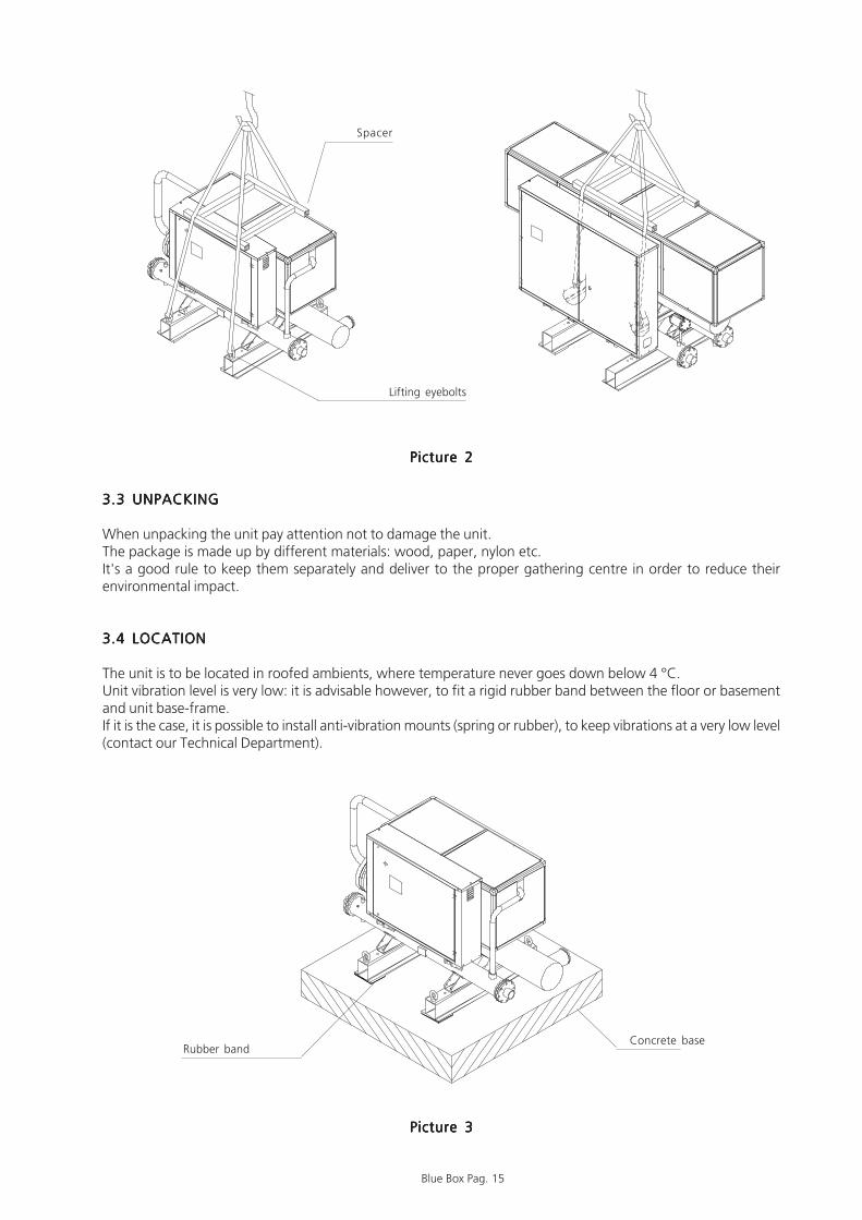
3.3 UNPACKING3.3 UNPACKING3.3 UNPACKING3.3 UNPACKING3.3 UNPACKING
When unpacking the unit pay attention not to damage the unit.The package is made up by different materials: wood, paper, nylon etc.It's a good rule to keep them separately and deliver to the proper gathering centre in order to reduce theirenvironmental impact.
3.4 LOCATION3.4 LOCATION3.4 LOCATION3.4 LOCATION3.4 LOCATION
The unit is to be located in roofed ambients, where temperature never goes down below 4 °C.Unit vibration level is very low: it is advisable however, to fit a rigid rubber band between the floor or basementand unit base-frame.If it is the case, it is possible to install anti-vibration mounts (spring or rubber), to keep vibrations at a very low level(contact our Technical Department).
Picture 3Picture 3Picture 3Picture 3Picture 3
Picture 2Picture 2Picture 2Picture 2Picture 2
Rubber bandConcrete base
Lifting eyebolts
Spacer

Blue Box Pag. 16
4. INSTALLATION4. INSTALLATION4. INSTALLATION4. INSTALLATION4. INSTALLATION
4.1 CLEARANCES4.1 CLEARANCES4.1 CLEARANCES4.1 CLEARANCES4.1 CLEARANCES
Minimum clearances for all units should be as following:- broadside: 1000 mm to allow hydraulic connection to the system and servicing operations;- front side: 1200 mm to allow access to electric board;- rear side: 1000 mm to allow maintenance operations;- heat exchanger connection side: enough space to extract the heat exchange bundle (* see dimensional drawings).
4.2 GENERAL RECOMMENDATIONS FOR WATER PIPING CONNECTIONS4.2 GENERAL RECOMMENDATIONS FOR WATER PIPING CONNECTIONS4.2 GENERAL RECOMMENDATIONS FOR WATER PIPING CONNECTIONS4.2 GENERAL RECOMMENDATIONS FOR WATER PIPING CONNECTIONS4.2 GENERAL RECOMMENDATIONS FOR WATER PIPING CONNECTIONS
Unit water pipework must be installed in accordance with national and local regulation and code.Please follow the recommendations reported below, when designing the unit water piping circuit (please refer tothe diagrams included in this manual).
Piping should be connected to the unit with flexible joints, in order to avoid vibration transmission and compensatethermal expansion (the same procedure should be adopted for the pumps).
On the pipings should be installed the following devices:- isolating valves, temperature gauges, pressure gauges for the ordinary maintenance or servicing operations.- thermometer probe pockets, if temperature gauges should not be present.- shut-off valves to separate the unit from the hydraulic circuit.- metallic filters (inlet pipings) with a mesh not larger than 1 mm, to prevent dusting in the heat exchangers.- vent valves, to be installed in the upper parts of the circuit, for air bleeding.- expansion tank with accessories (water filling group) for circuit pressurisation and water thermal expansion
compensation.- unload valve and if necessary drainage tank for circuit emptying during maintenance and seasonal stop.
It is highly recommended to install a safety valve on hydraulic circuit. InIt is highly recommended to install a safety valve on hydraulic circuit. InIt is highly recommended to install a safety valve on hydraulic circuit. InIt is highly recommended to install a safety valve on hydraulic circuit. InIt is highly recommended to install a safety valve on hydraulic circuit. Incase of dangerous situation (i.e. fire) the valve will discharge the systemcase of dangerous situation (i.e. fire) the valve will discharge the systemcase of dangerous situation (i.e. fire) the valve will discharge the systemcase of dangerous situation (i.e. fire) the valve will discharge the systemcase of dangerous situation (i.e. fire) the valve will discharge the systemavoiding explosions. The valve must be connected to a vent pipe with aavoiding explosions. The valve must be connected to a vent pipe with aavoiding explosions. The valve must be connected to a vent pipe with aavoiding explosions. The valve must be connected to a vent pipe with aavoiding explosions. The valve must be connected to a vent pipe with across area equal or greater than the valve and must be directed into across area equal or greater than the valve and must be directed into across area equal or greater than the valve and must be directed into across area equal or greater than the valve and must be directed into across area equal or greater than the valve and must be directed into asafe zone in which no injuries can be done to people.safe zone in which no injuries can be done to people.safe zone in which no injuries can be done to people.safe zone in which no injuries can be done to people.safe zone in which no injuries can be done to people.
Picture 4Picture 4Picture 4Picture 4Picture 4
1200
10001000
(*)

Blue Box Pag. 17
HYDRAULIC CIRCUIT DIAGRAMHYDRAULIC CIRCUIT DIAGRAMHYDRAULIC CIRCUIT DIAGRAMHYDRAULIC CIRCUIT DIAGRAMHYDRAULIC CIRCUIT DIAGRAM
1 Tank2 Circulating pump3 Non return valve4 Water filter5 Filling group6 Safety valve7 Expansion vessel8 Trap9 Manometer10 Thermometer11 Flexible joint12 Flow switch13 Vent valve14 Drain

Blue Box Pag. 18
4.3 WATER PIPE CONNECTIONS TO EVAPORATOR4.3 WATER PIPE CONNECTIONS TO EVAPORATOR4.3 WATER PIPE CONNECTIONS TO EVAPORATOR4.3 WATER PIPE CONNECTIONS TO EVAPORATOR4.3 WATER PIPE CONNECTIONS TO EVAPORATOR
Water inlet must be in correspondence with the connection labelled withWater inlet must be in correspondence with the connection labelled withWater inlet must be in correspondence with the connection labelled withWater inlet must be in correspondence with the connection labelled withWater inlet must be in correspondence with the connection labelled with
The hydraulic circuit must guarantee a constant water flow to theThe hydraulic circuit must guarantee a constant water flow to theThe hydraulic circuit must guarantee a constant water flow to theThe hydraulic circuit must guarantee a constant water flow to theThe hydraulic circuit must guarantee a constant water flow to theevaporator in any operating condition. If this should not happen, liquidevaporator in any operating condition. If this should not happen, liquidevaporator in any operating condition. If this should not happen, liquidevaporator in any operating condition. If this should not happen, liquidevaporator in any operating condition. If this should not happen, liquidrefrigerant could come back to the compressor causing its breakdown.refrigerant could come back to the compressor causing its breakdown.refrigerant could come back to the compressor causing its breakdown.refrigerant could come back to the compressor causing its breakdown.refrigerant could come back to the compressor causing its breakdown.
Compressors start and stop often, since the users cooling demand is not generally corresponding to the compressorscapacity. In the hydraulic circuits with low water volume, where the thermal inertia action is not appreciable, it isadvisable to verify if the water volume fulfils the following ratio:
24 · QCOMPTOT
M>= --------------------- N
where:
M = system water content [kg]QCOMPTOT = unit cooling capacity [kW]N = number of capacity steps
If the water volume does not reach the value given by the formula, it is advisable to provide the circuit with astorage vessel in order to get the required water volume (tank + circuit).The chilled water pipings and the storage vessel must be carefully insulated, in order to prevent condensation onthe tubes surface and to avoid circuit performance losses.
On all the units it is compulsory to install the flow switch that is providedOn all the units it is compulsory to install the flow switch that is providedOn all the units it is compulsory to install the flow switch that is providedOn all the units it is compulsory to install the flow switch that is providedOn all the units it is compulsory to install the flow switch that is providedwith the unit on the evaporator outlet connection labelled with:with the unit on the evaporator outlet connection labelled with:with the unit on the evaporator outlet connection labelled with:with the unit on the evaporator outlet connection labelled with:with the unit on the evaporator outlet connection labelled with:
It is compulsory to install on the water inlet piping a mesh metallic filter:It is compulsory to install on the water inlet piping a mesh metallic filter:It is compulsory to install on the water inlet piping a mesh metallic filter:It is compulsory to install on the water inlet piping a mesh metallic filter:It is compulsory to install on the water inlet piping a mesh metallic filter:should the flow switch or the filter not be present on the unit, theshould the flow switch or the filter not be present on the unit, theshould the flow switch or the filter not be present on the unit, theshould the flow switch or the filter not be present on the unit, theshould the flow switch or the filter not be present on the unit, thewarranty will terminate immediately.warranty will terminate immediately.warranty will terminate immediately.warranty will terminate immediately.warranty will terminate immediately.
Otherwise the evaporator may freeze, since the antifreeze thermostat would not work properly.All the units are provided with hydraulic connections in stainless steel male threaded type.

Blue Box Pag. 19
Caution: When executing hydraulic connections never use flames closeCaution: When executing hydraulic connections never use flames closeCaution: When executing hydraulic connections never use flames closeCaution: When executing hydraulic connections never use flames closeCaution: When executing hydraulic connections never use flames closeor inside the unit.or inside the unit.or inside the unit.or inside the unit.or inside the unit.
4.44.44.44.44.4 FLEXIBLE JOINTSFLEXIBLE JOINTSFLEXIBLE JOINTSFLEXIBLE JOINTSFLEXIBLE JOINTS
Flexible joints allow axial movements due to thermal expansion, eliminate vibrations and allow an easy assemblyand disassembly of the joint parts.To assembly joint act as follow:
1) Disconnect bolts and open the joint .
2) Move the gasket on the heat exchanger connection towardsthe shell .
3) Weld the counter-connection to the hydraulic circuit pipe.
4) Line up the connection and the counter-connection, placethe gasket in the original position and if possible lubricate iton contact areas with not aggressive oil or grease.
5) Assembly the joint and tighten the nuts.
Picture 5Picture 5Picture 5Picture 5Picture 5
Shell
Connection
Gasket
C o u n t e rconnection
Joint
ShellConnection
Gasket
C o u n t e rconnection
Pipe Weld
Connection
Gasket
Joint

Blue Box Pag. 20
4.5 WATER PIPE CONNECTION TO THE CONDENSER4.5 WATER PIPE CONNECTION TO THE CONDENSER4.5 WATER PIPE CONNECTION TO THE CONDENSER4.5 WATER PIPE CONNECTION TO THE CONDENSER4.5 WATER PIPE CONNECTION TO THE CONDENSER
Water inlet must be in correspondence with the connection labelled with
Hydraulic connections are of threaded steel pipes till 3" diameter and with flexible joints for diameters higher orequal to 114,3 mm.
For the units equipped with more than one compressor, water inlets and outlets must be joined together with amanifold.Location and dimensions are reported on dimensional sheet reported at the end of this manual.
When not using cooling tower but city water, it is highly recommended to install a pressostatic valve to assure thecorrect working of the unit.The pressostatic valve is also recommended for closed circuit installations. In fact this valve guarantees a regularoperation of the unit when changing condenser water conditions (for example when restarting after a weekendpause).The pressostatic valve is absolutely necessary if the tower water entering into the condenser can descendbelow 20 °C (see picture 6). The pressostatic valve must grant a condensing pressure higher than 12.5 barrelative.Contact our Company for further informations.
Refrigerant gas in
Refrigerant gas out
Leaving condenser water
Entering condenser water
1 Condenser2 Pressostatic valve3 Trap
Picture 6Picture 6Picture 6Picture 6Picture 6

Blue Box Pag. 21
4.6 DESUPERHEATER HYDRAULIC CONNECTIONS (optional)4.6 DESUPERHEATER HYDRAULIC CONNECTIONS (optional)4.6 DESUPERHEATER HYDRAULIC CONNECTIONS (optional)4.6 DESUPERHEATER HYDRAULIC CONNECTIONS (optional)4.6 DESUPERHEATER HYDRAULIC CONNECTIONS (optional)
For units provided with desuperheater is recommended to install a pressostatic valve to the condenser or amodulating three way valve with temperature probe fitted on condenser water inlet.
Water inlet must be in correspondence with the connection labelled with:
A 3 way modulating valve with temperature probe fitted on condenser water inlet can be provided instead of thepressostatic valve, to maintain the inlet condenser water temperature higher than 20 °C. See Picture 7.
In this way the system will be kept under optimal operating parameters. See paragraph 4.5.
Water inlet to recovery circuit must be in correspondence with theWater inlet to recovery circuit must be in correspondence with theWater inlet to recovery circuit must be in correspondence with theWater inlet to recovery circuit must be in correspondence with theWater inlet to recovery circuit must be in correspondence with theconnection labelled with:connection labelled with:connection labelled with:connection labelled with:connection labelled with:
4.7 HEAT RECOVERY EXCHANGE HYDRAULIC CONNECTIONS (Version /DC)4.7 HEAT RECOVERY EXCHANGE HYDRAULIC CONNECTIONS (Version /DC)4.7 HEAT RECOVERY EXCHANGE HYDRAULIC CONNECTIONS (Version /DC)4.7 HEAT RECOVERY EXCHANGE HYDRAULIC CONNECTIONS (Version /DC)4.7 HEAT RECOVERY EXCHANGE HYDRAULIC CONNECTIONS (Version /DC)
Refrigerant gas in
Refrigerant gas out
Leaving condenser water
Entering condenser water
1 Condenser2 3 way valve3 Circulating pump
IN
DESUPERHEATER WATERDESUPERHEATER WATERDESUPERHEATER WATERDESUPERHEATER WATERDESUPERHEATER WATER
Picture 7Picture 7Picture 7Picture 7Picture 7
IN
RECOVERY WATERRECOVERY WATERRECOVERY WATERRECOVERY WATERRECOVERY WATER
Blue Box Pag. 22
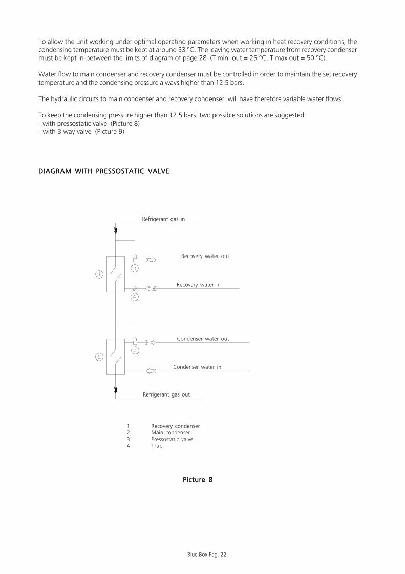
To allow the unit working under optimal operating parameters when working in heat recovery conditions, thecondensing temperature must be kept at around 53 °C. The leaving water temperature from recovery condensermust be kept in-between the limits of diagram of page 28 (T min. out = 25 °C, T max out = 50 °C).
Water flow to main condenser and recovery condenser must be controlled in order to maintain the set recoverytemperature and the condensing pressure always higher than 12.5 bars.
The hydraulic circuits to main condenser and recovery condenser will have therefore variable water flowsi.
To keep the condensing pressure higher than 12.5 bars, two possible solutions are suggested:- with pressostatic valve (Picture 8)- with 3 way valve (Picture 9)
DIAGRAM WITH PRESSOSTATIC VALVEDIAGRAM WITH PRESSOSTATIC VALVEDIAGRAM WITH PRESSOSTATIC VALVEDIAGRAM WITH PRESSOSTATIC VALVEDIAGRAM WITH PRESSOSTATIC VALVE
1 Recovery condenser2 Main condenser3 Pressostatic valve4 Trap
Refrigerant gas in
Refrigerant gas out
Recovery water in
Recovery water out
Condenser water in
Condenser water out
Picture 8Picture 8Picture 8Picture 8Picture 8
Blue Box Pag. 23
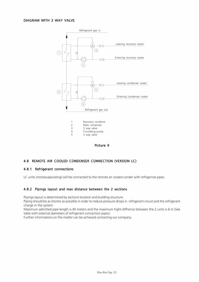
4.8 REMOTE AIR COOLED CONDENSER CONNECTION (VERSION LC)4.8 REMOTE AIR COOLED CONDENSER CONNECTION (VERSION LC)4.8 REMOTE AIR COOLED CONDENSER CONNECTION (VERSION LC)4.8 REMOTE AIR COOLED CONDENSER CONNECTION (VERSION LC)4.8 REMOTE AIR COOLED CONDENSER CONNECTION (VERSION LC)
4.8.1 Refrigerant connections4.8.1 Refrigerant connections4.8.1 Refrigerant connections4.8.1 Refrigerant connections4.8.1 Refrigerant connections
LC units (motoevaporating) will be connected to the remote air cooled conder with refrigernat pipes.
4.8.2 Pipings layout and max distance between the 2 sections4.8.2 Pipings layout and max distance between the 2 sections4.8.2 Pipings layout and max distance between the 2 sections4.8.2 Pipings layout and max distance between the 2 sections4.8.2 Pipings layout and max distance between the 2 sections
Pipings layout is determined by sections location and building structure.Piping should be as shorter as possible in order to reduce pressure drops in refrigerant circuit and the refrigerantcharge in the system.Maximum admitted pipe length is 40 meters and the maximum hight diffrence between the 2 units is 6 m (Seetable with external diameters of refrigerant connection pipes).Further informations on the matter can be achieved contacting our company.
1 Recovery condensr2 Main consenser3 3 way valve4 Circulating pump5 3 way valve
DIAGRAM WITH 3 WAY VALVEDIAGRAM WITH 3 WAY VALVEDIAGRAM WITH 3 WAY VALVEDIAGRAM WITH 3 WAY VALVEDIAGRAM WITH 3 WAY VALVE
Picture 9Picture 9Picture 9Picture 9Picture 9
Refrigerant gas in
Refrigerant gas out
Entering recovery water
Leaving recovery water
Entering condenser water
Leaving condenser water

Blue Box Pag. 24
CONNECTION PIPE EXTERNAL DIAMETERS TO REMOTE AIR COOLED CONDENSERCONNECTION PIPE EXTERNAL DIAMETERS TO REMOTE AIR COOLED CONDENSERCONNECTION PIPE EXTERNAL DIAMETERS TO REMOTE AIR COOLED CONDENSERCONNECTION PIPE EXTERNAL DIAMETERS TO REMOTE AIR COOLED CONDENSERCONNECTION PIPE EXTERNAL DIAMETERS TO REMOTE AIR COOLED CONDENSER
In the units with 2 compressors, the C1 circuithas the larger compressor and is located onthe right side looking the unit from the electricpanel side.The labels on the compressors identify thecircuits. Picture 10Picture 10Picture 10Picture 10Picture 10
Table 1Table 1Table 1Table 1Table 1
MODELOME GA V 2001 Cir cuit
Supply Liquid Supply Liquid Supply Liquid[mm] [mm] [mm] [mm] [mm] [mm]
19.1 C1 54 35 54 35 54 3522.1 C1 54 35 54 35 54 4227.1 C1 54 35 54 42 54 4233.1 C1 54 42 54 42 54 4239.1 C1 67 42 67 42 67 4238.2 C1 54 35 54 35 54 35
C2 54 35 54 35 54 3543.1 C1 67 42 67 42 67 5444.2 C1 54 35 54 35 54 42
C2 54 35 54 35 54 4247.1 C1 67 54 67 54 67 5452.1 C1 67 54 67 54 67 5454.2 C1 54 35 54 42 54 42
C2 54 35 54 42 54 4258.1 C1 67 54 67 54 67 5460.2 C1 54 42 54 42 54 42
C2 54 35 54 42 54 4265.2 C1 54 42 54 42 54 42
C2 54 42 54 42 54 4271.2 C1 67 42 67 42 67 42
C2 54 42 54 42 54 4277.2 C1 67 42 67 42 67 42
C2 67 42 67 42 67 4282.2 C1 67 42 67 42 67 42
C2 67 42 67 42 67 5486.2 C1 67 42 67 42 67 54
C2 67 42 67 42 67 5490.2 C1 67 54 67 54 67 54
C2 67 42 67 42 67 5493.2 C1 67 54 67 54 67 54
C2 67 54 67 54 67 54104.2 C1 67 54 67 54 67 54
C2 67 54 67 54 67 54116.2 C1 67 54 67 54 67 54
C2 67 54 67 54 67 54
Diameter of connecting pipes between unit andremote air cooled condenser
Dista nce be tw ee n unit a nd re mote a ir coole d conde nser [m]
10 20 30
�����������������������������������������������������
������
�����������������������������������������������������
������
����
����
��������������������������������������������������������������������������������������������������������������������������������������������������������������������������������������������������������������������������������������������������������������������������������������������������������������������������������������������������������������������������������������������������������������������������������������������������������������������������������
��������������������������������������������������������������������������������������������������������������������������������
������������������������������������������������������������������������������������������������������������������������������������������������������������������������������������������������������������������������������
����������������������������������������������������������������������������������������������������������������������������������������������������
����������������������������������������������������������������������������������������������������������������������������������������������������
��������������������������������������������������������������������������
��������������������������������������������������������������������������
��������������������������������������������������������������������������
��������������������������������������������������������������������������
����������������������������������������������������������������������������������������������������������������������������������������������������
��������������������������������������������������������������������������
������������������������������������������������������������������
������������������������������������������������������������������
���������������������������������
���������������������������������
���������������������������������
���������������������������������������������������������������������������������������������������������������������������������������������������������������
�����������������������������������������������������
������������������������������������������������������������������������������������������������������������������������������������������������������������������������������������������������������������������������������������������������������������������������������������������������������������������������������������������������������������������������������������������������������������������������������������������������������������������������������������������������������������������������������������������������������������������������������������������������������������������������������������������������������������������������������������������������������������������������������������������������������������������������������������������������������������������������������������������������������������������������������������������������������������������������������������������������������������������������������������������������������������������������������������������������������������������������������������������������������������������������������������������������������������������������������������������������������������������������������������������������������������������������������������������������������������������������
���������������������������������������������������������������������������������������������������������������������������������������������������������������������������������������������������������������������������������������������������������������������������������������������������������������������������������������������������������������������������������������������������������������������������������������������������������������������������������������������
������������������������������������������������������������������������������������������������������������������������������������������������������������������������������������������������������������������������������������������������������������������������������������������������������������������������������
������������������������������������������������������������������������������������������������������������������������������������������������������������������������������������������������������������������������������������������������������������������������������������������������������������������������������
���������������������������������������������������������������������������������������������������������������������������������������������������������������
���������������������������������������������������������������������������������������������������������������������������������������������������������������
���������������������������������������������������������������������������������������������������������������������������������������������������������������
���������������������������������������������������������������������������������������������������������������������������������������������������������������
������������������������������������������������������������������������������������������������������������������������������������������������������������������������������������������������������������������������������������������������������������������������������������������������������������������������������
���������������������������������������������������������������������������������������������������������������������������������������������������������������
C2C1

Blue Box Pag. 25
4.8.3 Recomendations for installation of the refrigerant line4.8.3 Recomendations for installation of the refrigerant line4.8.3 Recomendations for installation of the refrigerant line4.8.3 Recomendations for installation of the refrigerant line4.8.3 Recomendations for installation of the refrigerant line
Depending on the relative position of the condenser unit and evaporator sections, certain parameters should beobserved when installing the refrigerant line.Table 1 gives the diameter of pipe connections for LC versions.
4.8.4 Version LC: remote condenser above the evaporating unit:4.8.4 Version LC: remote condenser above the evaporating unit:4.8.4 Version LC: remote condenser above the evaporating unit:4.8.4 Version LC: remote condenser above the evaporating unit:4.8.4 Version LC: remote condenser above the evaporating unit:
a) Make a trap on the supply line, immediately downstream the compressor, to collect the liquid refrigerantwhich can be developed during the shutdown of unit and could irreparably damage the compressor.
b) Install siphons at least every 6 metres on vertical upward sections of pipelines in order to facilitate the return ofoil to the compressor.
c) Make sure there is a gradient of at least 1% on horizontal sections of the suction line in order to facilitate oildrainage in the correct direction of the flow.
d) Install a non return valve close to compressor inlet, to avoid that liquid refrigerant could fall into the compressorduring the shutdown of unit. This must be made when, with the unit off, the ambient temperature of condenseris higher than one of compressor.
< 6
m<
6 m
1 %
1 %
Condenser
Picture 11Picture 11Picture 11Picture 11Picture 11

Blue Box Pag. 26
4.8.5 Version LC: remote air cooled condenser below the evaporating unit:4.8.5 Version LC: remote air cooled condenser below the evaporating unit:4.8.5 Version LC: remote air cooled condenser below the evaporating unit:4.8.5 Version LC: remote air cooled condenser below the evaporating unit:4.8.5 Version LC: remote air cooled condenser below the evaporating unit:
No special suggestions for this installation.It is in any case advisable to install a non return valve close to compressor inlet, to avoid that liquid refrigerantcould fall into the compressor during the shutdown of unit. This must be made when, with the unit off, theambient temperature of condenser is higher than one of compressor.
4.9 SAFETY VALVES RELIEF4.9 SAFETY VALVES RELIEF4.9 SAFETY VALVES RELIEF4.9 SAFETY VALVES RELIEF4.9 SAFETY VALVES RELIEF
Pressure relief valves are fitted on the refrigerant circuit both on the high pressure side and low pressure side:according to main safety norms these valves must be vented outdoors, through a vent pipe.The vent pipe must have a size not lower than the relief valve and it must not hang on the valve.
Caution: The valve relief must be directed into a safe zone in which noCaution: The valve relief must be directed into a safe zone in which noCaution: The valve relief must be directed into a safe zone in which noCaution: The valve relief must be directed into a safe zone in which noCaution: The valve relief must be directed into a safe zone in which noinjuries can be caused to people.injuries can be caused to people.injuries can be caused to people.injuries can be caused to people.injuries can be caused to people.
1 %
Condenser
4.10 WATER QUALITY4.10 WATER QUALITY4.10 WATER QUALITY4.10 WATER QUALITY4.10 WATER QUALITY
When well or river water is applied for chilled water or condenser water, corrosion or dusting problems may occurdue to water quality. In this case it is necessary to analyse the quality of water by checking pH, electricalconductivity, ammonia ion content, sulphur and chloride content, total hardness, etc. and, if it is the case, providea chemical treatment.
Picture 12Picture 12Picture 12Picture 12Picture 12

Blue Box Pag. 27
TABLE 2 - FREEZING POINT FOR WATER-ANTIFREEZE MIXTURESTABLE 2 - FREEZING POINT FOR WATER-ANTIFREEZE MIXTURESTABLE 2 - FREEZING POINT FOR WATER-ANTIFREEZE MIXTURESTABLE 2 - FREEZING POINT FOR WATER-ANTIFREEZE MIXTURESTABLE 2 - FREEZING POINT FOR WATER-ANTIFREEZE MIXTURES
If ambient temperatures lower than the freezing point of water can beIf ambient temperatures lower than the freezing point of water can beIf ambient temperatures lower than the freezing point of water can beIf ambient temperatures lower than the freezing point of water can beIf ambient temperatures lower than the freezing point of water can beexpected, antifreeze mixtures in percentage indicated in table 2 must beexpected, antifreeze mixtures in percentage indicated in table 2 must beexpected, antifreeze mixtures in percentage indicated in table 2 must beexpected, antifreeze mixtures in percentage indicated in table 2 must beexpected, antifreeze mixtures in percentage indicated in table 2 must beutil ized.uti l ized.uti l ized.uti l ized.uti l ized.
If the glycole percentage is higher than 30%,units with special pum sealsIf the glycole percentage is higher than 30%,units with special pum sealsIf the glycole percentage is higher than 30%,units with special pum sealsIf the glycole percentage is higher than 30%,units with special pum sealsIf the glycole percentage is higher than 30%,units with special pum sealsmust be used.must be used.must be used.must be used.must be used.
4.11 LOW TEMPERATURE WATER AT CONDENSER4.11 LOW TEMPERATURE WATER AT CONDENSER4.11 LOW TEMPERATURE WATER AT CONDENSER4.11 LOW TEMPERATURE WATER AT CONDENSER4.11 LOW TEMPERATURE WATER AT CONDENSER
The units are not planned to work with condenser cooling water below 20 °C. Below this limit, the unit couldrequire substantial changes. In case of necessity please contact our Company.
When chilled water at the evaporator outlet is below 5 °C, it is necessary to operate with a mixture of water andethylene glycol. In this case, control and antifreeze set points must be changed:This value is normally set at factory.
The ethylene glycol percentage must be chosen in relation to the desired chilled water temperature (see Table 2).
Standard units are not designed to operate with water temperature belowStandard units are not designed to operate with water temperature belowStandard units are not designed to operate with water temperature belowStandard units are not designed to operate with water temperature belowStandard units are not designed to operate with water temperature below5°C at the evaporator outlet. In order to work below this limit, the unit5°C at the evaporator outlet. In order to work below this limit, the unit5°C at the evaporator outlet. In order to work below this limit, the unit5°C at the evaporator outlet. In order to work below this limit, the unit5°C at the evaporator outlet. In order to work below this limit, the unitshould need some structural modifications. In this case contact ourshould need some structural modifications. In this case contact ourshould need some structural modifications. In this case contact ourshould need some structural modifications. In this case contact ourshould need some structural modifications. In this case contact ourCompany.Company.Company.Company.Company.
4.12 OPERATION WITH LOW TEMPERATURE CHILLED WATER AT EVAPORATOR4.12 OPERATION WITH LOW TEMPERATURE CHILLED WATER AT EVAPORATOR4.12 OPERATION WITH LOW TEMPERATURE CHILLED WATER AT EVAPORATOR4.12 OPERATION WITH LOW TEMPERATURE CHILLED WATER AT EVAPORATOR4.12 OPERATION WITH LOW TEMPERATURE CHILLED WATER AT EVAPORATOR
LIQUID OUTLET TEMPERATURE
OR MINIMUM AMBIENT TEMPERATURE (°C)
FREEZING POINT (°C) -5° -10° -15° -20° -25° -30° -35° -40° -45°
NON FREEZING LIQUID
ETHYLENE GLYCOL 6 22 30 36 41 46 50 53 56
PROPYL GLYCOL 15 25 33 39 44 48 51 54 57
METHANOL 8 14 20 26 30 34 38 41 45
CALCIUM CHLORIDE 9 14 18 21 24 26 27 28 30
TEMPER -20
TEMPER -40 ---
TEMPER -60
TIFOXITE 50 60 63 69 73 ---
FREEZIUM 10 20 25 30 34 37 40 43 45
PEKASOL 50 59 68 75 81 86 90 ---
-40°
% WEIGHT PERCENTAGE
40
50
T -20°C
T -40°C
T -60°C
---
-20° -25° -30° -35°+0° -5° -10° -15°
������
������
������
������
������
���
���
�����
������
����
����
����
��
��
��
����
����
����
����
����
��
��
����
������
����
����
����
��
��
����
������
����
����
����
��
��
����
����
����
���� ��
����
��
��
��
����
����
����
����
����
��
��
����
������
����
����
��
��
��
���� ��
������
����
����
��
��
��
������������������������������������������������������������������������������������������������������������������������������������������������������������������������������������������������������������������������������������������������������������������

Blue Box Pag. 28
OPERATION LIMITSOPERATION LIMITSOPERATION LIMITSOPERATION LIMITSOPERATION LIMITS
Water thermal difference for all versions: min: 3 °C ; max: 8 °C
OMEGA V 2001 /LCOMEGA V 2001 /LCOMEGA V 2001 /LCOMEGA V 2001 /LCOMEGA V 2001 /LC
OMEGA V 2001OMEGA V 2001OMEGA V 2001OMEGA V 2001OMEGA V 2001
Water thermal difference for all versions: min: 3 °C ; max: 8 °C
Leaving temperature of condenser cooling water [°C]Evap
orat
or le
avin
g w
ater
tem
pera
ture
[°C
]
0
5
10
15
20
15 20 25 30 35 40 45 50 55 60
Refrigeratore Chiller
Raffreddamento Cooling
0
5
10
15
20
15 20 25 30 35 40 45 50 55 60
Refrigeratore Chiller
Raffreddamento Cooling
Condensing temperature [°C]
Evap
orat
or le
avin
g w
ater
tem
pera
ture
[°C
]

Blue Box Pag. 29
PRESSURE DROP CONDENSERSPRESSURE DROP CONDENSERSPRESSURE DROP CONDENSERSPRESSURE DROP CONDENSERSPRESSURE DROP CONDENSERS
Il salto termico per tutte le versioni deve essere compreso fra: 3 °C, max: 8 °C
Pres
sure
dro
p [k
Pa]
Water flow of each condenser [l/s]
10 20 30 40 50 60 70 80 9010010
20
30
40
50
60708090
100
19.1
-38.
2
22.1
-44.
227
.1-5
4.2-
60.2
33.1
-65.
2-71
.2
39.1
-77.
2-82
.2
43.1
-86.
2-90
.2
47.1
-93.
252
.1-1
04.2
58.1
-116
.2
4.13 4.13 4.13 4.13 4.13 CONDENSER AND EVAPORATOR WATER FLOW RATE CONDENSER AND EVAPORATOR WATER FLOW RATE CONDENSER AND EVAPORATOR WATER FLOW RATE CONDENSER AND EVAPORATOR WATER FLOW RATE CONDENSER AND EVAPORATOR WATER FLOW RATE
LThe nominal water flow rate given by Blue Box is referred to a thermal difference between the evaporator inletand outlet of 5 °C, at the nominal cooling capacity.Maximum allowed flow rate is the one that presents a thermal difference of 3 °C: higher values could result in ainadmissible pressure drop with possibility of erosion in the exchanger.The minimum water flow rate allowed is the one presenting a thermal difference of 8 °C: lower values may causetoo low evaporating temperatures or too high condensing temperatures with the action of safety devices whichwould stop of the unit.
4.14 4.14 4.14 4.14 4.14 CHILLED WATER TEMPERATURE TO THE EVAPORATORCHILLED WATER TEMPERATURE TO THE EVAPORATORCHILLED WATER TEMPERATURE TO THE EVAPORATORCHILLED WATER TEMPERATURE TO THE EVAPORATORCHILLED WATER TEMPERATURE TO THE EVAPORATOR
The minimum temperature allowed at the evaporator outlet is 5 °C: for lower temperatures please refer toparagraph 4.12. The maximum temperature allowed at the evaporator inlet is 20 °C. For higher temperatures itis necessary to adopt proper solutions: (split circuits, three way valves, by-pass, storage vessels).
Pressure drop is referred to each condenser [kPa]

Blue Box Pag. 30
Water thermal difference for all versions: min: 3 °C ; max: 8 °C
PRESSURE DROP EVAPORATORSPRESSURE DROP EVAPORATORSPRESSURE DROP EVAPORATORSPRESSURE DROP EVAPORATORSPRESSURE DROP EVAPORATORSPr
essu
re d
rop
[kPa
]
Water flow [l/s]
Pres
sure
dro
p [k
Pa]
Water flow [l/s]
Water thermal difference for all versions: min: 3 °C ; max: 8 °C
8 9 10 20 30 40 50 60 70 8010
20
30
40
50
60708090
100
52.1
54.2
-58.
1-60
.265
.2
71.2
-77.
2
116.
2
82.2
-86.
2-90
.2-9
3.2-
104.
2
5 6 7 8 9 10 20 3010
20
30
40
50
60708090
100
19.1
22.1
38.2-39.1 27.1-33.1
43.1-4
4.2-47.1

Blue Box Pag. 31
Electrical connections must comply with wiring diagram supplied with the unit and conform to establishedregulations.
Earth connection is compulsory. Installer must connect ground cable with ground bar in the electric board labelledwith PE.
It must be verified that electric supply is corresponding to the unit electric nominal data (tension, phases, frequency)reported on the label in the front panel of the unit.
The line voltage fluctuations must not be more than ±5% of the nominal value, while the voltage unbalancebetween one phase and another must not exceed 2%. If those tolerances should not be respected, pleasecontact our Technical Department to provide proper devices.
Check power connection for correct phase sequence.
For cable connection drill the cover on the side of electric control box, according to the model.
The control circuit derives from the power supply through a transformer fitted inside the electrical panel.
The control circuit is protected by fuses.
4.15 ELECTRICAL CONNECTIONS4.15 ELECTRICAL CONNECTIONS4.15 ELECTRICAL CONNECTIONS4.15 ELECTRICAL CONNECTIONS4.15 ELECTRICAL CONNECTIONS
4.15.1 Generality4.15.1 Generality4.15.1 Generality4.15.1 Generality4.15.1 Generality
Before every operation on the electric section, be sure that the electricBefore every operation on the electric section, be sure that the electricBefore every operation on the electric section, be sure that the electricBefore every operation on the electric section, be sure that the electricBefore every operation on the electric section, be sure that the electricsupply is disconnected.supply is disconnected.supply is disconnected.supply is disconnected.supply is disconnected.
Power cable and line protection must be sized according to the specificationPower cable and line protection must be sized according to the specificationPower cable and line protection must be sized according to the specificationPower cable and line protection must be sized according to the specificationPower cable and line protection must be sized according to the specificationreported on the wiring diagram and the form enclosed with the unit.reported on the wiring diagram and the form enclosed with the unit.reported on the wiring diagram and the form enclosed with the unit.reported on the wiring diagram and the form enclosed with the unit.reported on the wiring diagram and the form enclosed with the unit.
Electric supply must be in the limits shown: in the opposite case warrantyElectric supply must be in the limits shown: in the opposite case warrantyElectric supply must be in the limits shown: in the opposite case warrantyElectric supply must be in the limits shown: in the opposite case warrantyElectric supply must be in the limits shown: in the opposite case warrantywill terminate immediately.will terminate immediately.will terminate immediately.will terminate immediately.will terminate immediately.
Supply cable fixing: supply cable must be fixed so as to withstand anySupply cable fixing: supply cable must be fixed so as to withstand anySupply cable fixing: supply cable must be fixed so as to withstand anySupply cable fixing: supply cable must be fixed so as to withstand anySupply cable fixing: supply cable must be fixed so as to withstand anytensile and torsional stress.tensile and torsional stress.tensile and torsional stress.tensile and torsional stress.tensile and torsional stress.
To supply the crankcase heaters procede as follows:1) Close the main switch turning it from position “0” to position “1”2) Check that the display shows “OFF”3) Check that unit is in “OFF” position and external interlock is open4) If the display shows the alarm “WRONG PHASE SEQUENCE”, invert 2 phases
of the power supply.5) The unit must remain for a minimum of 12 hours in this situation to supply
the crankcase heaters
Crankcase heaters must be supplied at least 12 hours before start up byCrankcase heaters must be supplied at least 12 hours before start up byCrankcase heaters must be supplied at least 12 hours before start up byCrankcase heaters must be supplied at least 12 hours before start up byCrankcase heaters must be supplied at least 12 hours before start up bysimply closing the main switch (heaters are automatically supplied whensimply closing the main switch (heaters are automatically supplied whensimply closing the main switch (heaters are automatically supplied whensimply closing the main switch (heaters are automatically supplied whensimply closing the main switch (heaters are automatically supplied whenmain switch is closed).main switch is closed).main switch is closed).main switch is closed).main switch is closed).
Picture 13Picture 13Picture 13Picture 13Picture 13

Blue Box Pag. 32
ELECTRICAL BOARD LAYOUT - STANDARD UNITS WITH 1 AND 2 COMPRESSORSELECTRICAL BOARD LAYOUT - STANDARD UNITS WITH 1 AND 2 COMPRESSORSELECTRICAL BOARD LAYOUT - STANDARD UNITS WITH 1 AND 2 COMPRESSORSELECTRICAL BOARD LAYOUT - STANDARD UNITS WITH 1 AND 2 COMPRESSORSELECTRICAL BOARD LAYOUT - STANDARD UNITS WITH 1 AND 2 COMPRESSORS
Standard unit with1 compressor
Picture 14Picture 14Picture 14Picture 14Picture 14
Picture 15Picture 15Picture 15Picture 15Picture 15
Standard unit with2 compressors
P OS . DE S CRIP T ION P OS . DE S CRIP T IONFR1 THERMAL PROTECTION COMPRESSOR 1 KM10 CONTACTOR Y COMPRESSOR 2FR2 THERMAL PROTECTION COMPRESSOR 2 KM41 POW. FACTOR CORRECTION CONTACTOR COMPR. 1FU1 FUSES COMPRESSOR 1 KM42 POW. FACTOR CORRECTION CONTACTOR COMPR. 2FU2 FUSES COMPRESSOR 2 KM5 CONTACTOR COMPRESSOR 1, DFU41 POW. FACTOR CORRECT. CONDENSER FUSES COMPR. 1 KM6 CONTACTOR D COMPRESSOR 2FU42 POW. FACTOR CORRECT. CONDENSER FUSES COMPR. 2 KM9 CONTACTOR Y COMPRESSOR 1FU50 AUX. TRANSF. CIRCUIT FUSES KT1 TIMER COMPRESSOR 1FU51 AUX. CIRCUIT FUSES KT2 TIMER COMPRESSOR 2FU52 CONTROL FUSES KT5 TIMER COMPRESSOR 1 STARTFU56 PHASE SEQ. RELAY FUSES KT6 TIMER COMPRESSOR 2 STARTKA5 PHASE SEQUENCE RELAY QS MAIN SWITCHKM1 COMPRESSOR 1 CONTACTOR, Y TC1 AUX.TRANSFORMERKM2 COMPRESSOR 2 CONTACTOR, Y
����������������������������
����������������������������
����������������������������
����������������������������
����������������������������
������������������������������������������������������������������������������������������������������������������������������������������������������������������������������������������������������������������������������������������������������������������������������������������������������������������������������������������������������������������������������������������������������������������������������������������������������������������������������������������������������������������������������������������������������������������������������������������������������������������������������������������������������������������������������������������������������������������������������������������������������������������������������������������������������������������������������������������������������������������������������������������������������������������������������������������������������������������������������������������������������������������������������������������������������������������������������������������������������������������������������������������������������������������������������������������������������������������������������������������������������������������������������������������������������������������������������������������������������������������������������������������������������������������������������������������������������������������������������������������������������������������������������������������������������������������������������������������������������������������������������������������������������������������������������������������������������������������������������������������������������������������������������������������������������������������������������������������������������������������������������������������������������������������������������������������������������������������������������������������������������������������������������������������������������������������������������������������������������������������������������������������������������������������������������������������������������������������������������������������������������������������������������������������������������������������������������������������������������������������������������������������������������������������������������������������������������������������������������������������������������������������������������������������������������������������������������������������������������������������������������������������������������������������������������������������������������������������������������������������������������������������������������������������������������������������������������������������������������������������������������������������������������������������������������������������������������������������������������������������������������������������������������������������������������������������������������������������������������������������������������������������������������������������������������������������������������������������������������������������������������������������������������������������������������������������������������������������������������������������������������������������������������������������������������������������������������������������������������������������������������������������������������������������������������������������������������������������������������������������������������������������������������������������������������������������������������������������������������������������������������������������������������������������������������������������������������������������������������������������������������������������������������������������������������������������������������������������������������������������������������������������������������������������������������������������������������������������������������������������������������������������������

Blue Box Pag. 33
4.15.4 Microprocessor controller on the unit4.15.4 Microprocessor controller on the unit4.15.4 Microprocessor controller on the unit4.15.4 Microprocessor controller on the unit4.15.4 Microprocessor controller on the unit
OMEGA.V 2001 Chillers are controlled by pCO2 microprocessor.
The pCO2 electronic microprocessor, controls refrigerating units with 2 compressors and with 2 capacity stepseach.
The program controls water cooled chillers with shell and tube heat exchangers, the compressors, the timesettings and alarms, as well as “accessory” functions,
The required hardware has been optimised to maximise the utility of available inputs and outputs, while inter-board connections and user-terminal interface are ensured by means of the pLANE, using the serial connectorRS485, dedicated for network construction.Each unit can be connected by a 485 serial line to supervisor and/or tele-maintenance systems.Detailed informations on the control are reported in the manual enclosed with the unit.
4.15.3 Circulating pump electrical connections4.15.3 Circulating pump electrical connections4.15.3 Circulating pump electrical connections4.15.3 Circulating pump electrical connections4.15.3 Circulating pump electrical connections
The pumps of evaporator and condenser must be started up before theThe pumps of evaporator and condenser must be started up before theThe pumps of evaporator and condenser must be started up before theThe pumps of evaporator and condenser must be started up before theThe pumps of evaporator and condenser must be started up before thechiller and shut down after the latter (recommended minimum advance/chiller and shut down after the latter (recommended minimum advance/chiller and shut down after the latter (recommended minimum advance/chiller and shut down after the latter (recommended minimum advance/chiller and shut down after the latter (recommended minimum advance/delay interval: 60 seconds).delay interval: 60 seconds).delay interval: 60 seconds).delay interval: 60 seconds).delay interval: 60 seconds).
4.15.5 Serial RS485 interface (opzion)4.15.5 Serial RS485 interface (opzion)4.15.5 Serial RS485 interface (opzion)4.15.5 Serial RS485 interface (opzion)4.15.5 Serial RS485 interface (opzion)
The serial card for remote supervision or remote assistance by computer is available on requestThe serial card for remote supervision or remote assistance by computer is available on requestThe serial card for remote supervision or remote assistance by computer is available on requestThe serial card for remote supervision or remote assistance by computer is available on requestThe serial card for remote supervision or remote assistance by computer is available on requestfor all OMEGA.V 2001 units.for all OMEGA.V 2001 units.for all OMEGA.V 2001 units.for all OMEGA.V 2001 units.for all OMEGA.V 2001 units.
The serial board is fitted in the connection board (see figure of large board).Connection with the serial line for supervision or tele-maintenance is made by standard RS485 and by means ofserial boards.When the serial board is fitted, communication protocol Carel, Modbus-jbus and BacNet are available. Note thatsystems using the Lon-Talk protocol require a special board.Conversion gateways are not required.
4.15.2 Potential free contacts4.15.2 Potential free contacts4.15.2 Potential free contacts4.15.2 Potential free contacts4.15.2 Potential free contacts
The following potential free contacts are availablei:- 1 potential free contact for general alarm (terminals 100 - 101 - 102)- 1 potential free contact for each compressor (option)
Normally open external water pump contactor terminals must be connected in series to terminalNormally open external water pump contactor terminals must be connected in series to terminalNormally open external water pump contactor terminals must be connected in series to terminalNormally open external water pump contactor terminals must be connected in series to terminalNormally open external water pump contactor terminals must be connected in series to terminal1-2 of electric panel1-2 of electric panel1-2 of electric panel1-2 of electric panel1-2 of electric panel.Upon request, some potential free contacts fof the compressors (on/off), can be supplied as option to control thecondenser pump.

Blue Box Pag. 34
4.15.6 User interface – Microprocessor pCO4.15.6 User interface – Microprocessor pCO4.15.6 User interface – Microprocessor pCO4.15.6 User interface – Microprocessor pCO4.15.6 User interface – Microprocessor pCO22222
The back-lit LCD display comprises 4 lines and 20 columns.
Picture 16Picture 16Picture 16Picture 16Picture 16
Menu key: press when in any display to return to the first menu page.
Maintenance key: press to access maintenance functions.
Print key: associated function currently unavailable.
"I/O" key: press to access pages displaying current status of digital inputs and outputs,values of analogue inputs and outputs.
"Clock" key: press to access clock functions.
"Set" key: press to access pages for modifying operating parameters.
"prog" key: press to access service pages.
Besides the liquid crystal display, the user interface features the following keys with relative functions:

Blue Box Pag. 35
Electronic components could be damaged by air temperature below -20Electronic components could be damaged by air temperature below -20Electronic components could be damaged by air temperature below -20Electronic components could be damaged by air temperature below -20Electronic components could be damaged by air temperature below -20°C.°C.°C.°C.°C.
Enter key: press to access fields with modifiable parameters, then to confirm modifications.
“? info” key: press the key to access the pages to change the address of the unit connected to theterminal.
"Summer" (blue) and "Winter" (red) keys: OMEGA V 2001 units operate as chiilleronly. “Summer” and “Winter” keys are not used.
on/off key: press this key to switch the unit from stand-by to on and vice-versa.
Alarm key: press to silence the alarm buzzer, display (and cancel as necessary) activated alarms.
Arrow keys: press to pass from one page to another or to change settings when in amodifiable field.

Blue Box Pag. 36
5. START UP5. START UP5. START UP5. START UP5. START UP
5.1 PRELIMINARY CHECKS5.1 PRELIMINARY CHECKS5.1 PRELIMINARY CHECKS5.1 PRELIMINARY CHECKS5.1 PRELIMINARY CHECKS
- Verificare che l'allacciamento elettrico sia stato eseguito in maniera corretta e che tutti i morsetti siano serratistrettamente.
- The voltage at the phase R S T clamps must be 400 V ± 5% (or teh nominal for units with special voltage). If thepower supply has frequent changes, please contact our Technical Department to select the necessary protections.
- Check that the display shows the refrigerant gas pressure of the refrigerant circuits.
- Check that there is not any refrigerant leak by means of a leak finder.
- Check that the crankcase heaters are correctly supplied.
- Verify that heaters are working correctly: after the warm up period the crankcase must be warm to the touchand must have at least a temperature 10 - 15 °C higher than ambient temperature.
- Check that all hydraulic connections are correctly installed and all indications on unit labels are observed.
- The system must be purged in order to eliminate any air that might have remained in the unit by means of ventvalves, previously installed, together with an expansion tank of a proper size (see paragraph 4.2).
Crankcase heaters must be supplied at least 12 hours before start up byCrankcase heaters must be supplied at least 12 hours before start up byCrankcase heaters must be supplied at least 12 hours before start up byCrankcase heaters must be supplied at least 12 hours before start up byCrankcase heaters must be supplied at least 12 hours before start up bysimply closing the main switch (heaters are automatically supplied whensimply closing the main switch (heaters are automatically supplied whensimply closing the main switch (heaters are automatically supplied whensimply closing the main switch (heaters are automatically supplied whensimply closing the main switch (heaters are automatically supplied whenmain switch is closed).main switch is closed).main switch is closed).main switch is closed).main switch is closed).
5.2 WORKING DESCRIPTION5.2 WORKING DESCRIPTION5.2 WORKING DESCRIPTION5.2 WORKING DESCRIPTION5.2 WORKING DESCRIPTION
5.2.1 General5.2.1 General5.2.1 General5.2.1 General5.2.1 General
The regulator maintains the water temperature of the evaporator at the set value; this is achieved through thecontrol of compressor operation.The controller has 2-step capacity control over each compressor.The controller also actuates all the components of the cooling system, the alarms and the “accessory functions”.Almost all operating parameters (set points, differentials, calibration, delays, etc.) described below can be configuredfrom the program pages visible on display. See also the manual of pCO2 controller.
5.2.2 Unit in stand-by mode5.2.2 Unit in stand-by mode5.2.2 Unit in stand-by mode5.2.2 Unit in stand-by mode5.2.2 Unit in stand-by mode
The regulator maintains water temperature of the evaporator at the set value through the control of compressoroperation.The controller has 2-step capacity control over each compressor.The microprocessr also controls all the components of the cooling system, the alarms and the “accessory” functions.Almost all operating parameters (set points, differentials, calibration, delays, etc.) described below can be configuredfrom the program pages.For specific information see the instruction manuala of pCO2 controller.
Large refrigerant gas leakage change the composition of the remainingLarge refrigerant gas leakage change the composition of the remainingLarge refrigerant gas leakage change the composition of the remainingLarge refrigerant gas leakage change the composition of the remainingLarge refrigerant gas leakage change the composition of the remainingrefrigerant gas mixture and reduce the performance of the unit.refrigerant gas mixture and reduce the performance of the unit.refrigerant gas mixture and reduce the performance of the unit.refrigerant gas mixture and reduce the performance of the unit.refrigerant gas mixture and reduce the performance of the unit.

Blue Box Pag. 37
5.2.3 Enabling the unit5.2.3 Enabling the unit5.2.3 Enabling the unit5.2.3 Enabling the unit5.2.3 Enabling the unit
The unit can be put into service from stand-by mode after an external permissive has been closed, when the “on/off” key is pressed or by means of a serial signal.The controller outputs controlling the various sections of the chiller unit are activated in accordance with theoperation time settings. If the “on” key is pressed before the closing of the external permissive, the display showsthe permissive not closed.The compressors can start only if the pumps of the condenser and of the evaporator are already working.
5.2.4 Pumps control5.2.4 Pumps control5.2.4 Pumps control5.2.4 Pumps control5.2.4 Pumps control
The microprocessor does not control the pumps of condenser and evaporator.When the unit sets from operating status to stand-by by means of the opening of the external permissive, pumpshutdown must be delayed for a certain time after the shutdown of the last compressor, in order to take fulladvantage of thermal accumulation.
5.2.5 Compressors start-up5.2.5 Compressors start-up5.2.5 Compressors start-up5.2.5 Compressors start-up5.2.5 Compressors start-up
The controller allows compressors start-up if the flowmeter input is closed by the time of start-up delay. In theevent that the flowmeter input is opened after compressor start-up, it will in any case be delayed before chillershutdown.An alarm will be displayed in the event of unit shutdown due to the opening of the flowmeter input.Compressor start-up, shutdown and step control will be carried out by the controller according to system requirementsand selected operations.
5.2.6 Chiller operation5.2.6 Chiller operation5.2.6 Chiller operation5.2.6 Chiller operation5.2.6 Chiller operation
The microprocessor does not control the pumps of condenser and evaporator.The control maintains the water temperature inside the limits of the set values. In the standard units the if thecontroller acts on evaporator input water, the control of compressor outlets and relative step capacity will dependon the difference between the input water temperature and the set point.
5.2.7 Evaporator antifrost5.2.7 Evaporator antifrost5.2.7 Evaporator antifrost5.2.7 Evaporator antifrost5.2.7 Evaporator antifrost
In the event that the output water temperature from a heat exchanger is lower than the antifrost limit value, thecontroller will shut down all the compressors and will give the antifrost alarm.In the event that the output water temperature from a heat exchanger is lower than the antifrost limit value, thecontroller will cut in to shut down compressor operation in the chiller circuit, and will give the antifrost alarm.Manual cancelling of alarms and compressor restart will only be possible when the water temperature at the heatexchanger outlet causing the alarm is equal to or greater than the antifrost limit value, increased by the antifrostdifferential.The antifrost alarm will automatically shut down the entire unit and therefore all compressors.The antifrost alarm will only appear when the unit is on (but not when in stand-by mode).
5.2.85.2.85.2.85.2.85.2.8 Antifrost heater (opzion) Antifrost heater (opzion) Antifrost heater (opzion) Antifrost heater (opzion) Antifrost heater (opzion)
In the event of an antifrost alarm, the antifrost heater output is automatically enabled.The output remains enabled as long as the conditions causing the alarm persist.While the alarm will only be given when the unit is switched on, the output of the antifrost heater will remainenabled even when the unit is in stand-by status.
5.2.9 Working of compressors5.2.9 Working of compressors5.2.9 Working of compressors5.2.9 Working of compressors5.2.9 Working of compressors
When the unit is operating correctly (without any general alarms as described above) and the water temperaturerequires, the microprocessor activates the compressors.The compressors and relative step capacity operation are activated with a time delay in order to prevent highbreakaway current.Before activating a compressor the controller checks the delivery pressure on the basis of the value read by thetransducer and the status of the high pressure switch. A check is also made of the compressor motor winding

Blue Box Pag. 38
temperature by verification of the status of the overload switch input.When the compressor has been activated, the opening of the one of the above digital inputs causes its immediateshutdown and the display of the relative alarm.In any case, each compressor will operate for a minimum time, unless shut down by a serious alarm.The alarms that can cause the compressor to shut down during the minimum operating time are the high pressurealarm and the compressor overload alarm.During compressor operation, delivery and suction pressure ratings are checked by the respective probes.Once shut down, the compressors can only be restarted after the minimum shutdown time has elapsed, and inany case after the minimum interval between two consecutive compressor start-ups has elapsed.The consecutive start-up of two compressors, or the start-up of a compressor followed by the relative step capacityoperation will take place with a minimum delay equal to the time of step start-up.Start-up and shutdown of two compressors or capacity steps will operate with a minimum set delay time, equalto the time of step start-up.The consecutive shutdown of two compressors, or the consecutive deactivation of the step capacity operationsand of the relative compressor, will be carried out with delays equal to the time for step deactivation.
5.2.10 High and low pressure alarms5.2.10 High and low pressure alarms5.2.10 High and low pressure alarms5.2.10 High and low pressure alarms5.2.10 High and low pressure alarms
Delivery (high) pressure and suction (low) pressure are checked by the controller by means of probes.When the compressor is operating, the controller checks that:- Delivery pressure is always below the safety value set for cooling operation. In the event that these values are
exceeded, the controller immediately shuts down compressor operation and displays a high pressure alarm. Thehigh pressure alarm can be removed manually on the controller only when the pressure rating read by thedelivery pressure probe has dropped below the value that caused the shutdown.
- Suction pressure is always higher than the set safety value during cooling operation. In the event that the valuesread by the suction pressure probe are lower than the set values, the controller immediately shuts down compressoroperation and displays a low pressure alarm. This alarm is not instantaneous, and is disregarded with relativedelays at unit start-up and during operation. The alarm can be cancelled manually. Low pressure alarms can becancelled by the controller only when the pressure reading made by the suction pressure probe is greater thanthe value that tripped the alarm.
5.2.11 5.2.11 5.2.11 5.2.11 5.2.11 Compressor and step capacity controlCompressor and step capacity controlCompressor and step capacity controlCompressor and step capacity controlCompressor and step capacity control
Start up and capacity step operation of compressors are enabled by the controller in accordance to variations inreference water temperature in relation to the set point.The reference water temperature is normally the one read at the inlet on the chiller unit.
The control of compressors and capacity steps at the increase of the thermal load can be carried out in twodiffrent ways:
- The arrangement of power steps in “FPM” operation ensures that all compressors are activated and stepcontrolled before full capacity is requested.
- In “CPM” step capacity control, as the operating requirement increases, each compressor is progressivelyactivated to operate at full capacity before the next is activated.
As the load request declines, the number of power steps activated by the controller will be accordingly reduced.The reduction in the request for power steps by the controller is carried out with the reverse procedure to that ofactivation: as the load decreases, compressor operation is reduced by steps then shut down (“FMP” operation),or the operation of each compressor is progressively reduced by steps then shut down (“CPM”).
The even distribution of operating hours over all compressors in the unit is ensured by selecting rotation ofoperation requests.When this function is active, the first compressor to be activated is also the first to be shut down (the compressorthat has not be activated for the longest time will in any case be activated).The capacity control of compressors can be carried out either by steps or continuously.During capacity step control, each solenoid valve of compressor represents a power step.
In continuous capacity step control (upon request), compressor power is adjusted by the movement of the stepcontrol cylinder. Cylinder movement is actuated by two solenoid valves; one to increase power yield, the other to

Blue Box Pag. 39
reduce it.The cylinder moves in response to pulses by the solenoids; cylinder position and the degree of step control isregulated by the controller, on the basis of the time configured for the entire cylinder stroke.
Shutdown and start-up of compressors are always carried out at reduced capacity step.
5.2.12 Desuperheater (option)5.2.12 Desuperheater (option)5.2.12 Desuperheater (option)5.2.12 Desuperheater (option)5.2.12 Desuperheater (option)
The desuperheater recovers part of the total power to be dispersed through the condenser and produces hotwater (design entering water temperature 40 °C; leaving water temperature 45 °C). It is therefore possible tosave energy and have an economic benefit. Each refrigerant circuit is equipped with a shell and tube desuperheaterconnected in series to the main condenser.For the hydraulic circuit see paragraph 4.6.
5.2.13 5.2.13 5.2.13 5.2.13 5.2.13 Heat recovery Heat recovery Heat recovery Heat recovery Heat recovery (OMEGA V 2001/DC only) (OMEGA V 2001/DC only) (OMEGA V 2001/DC only) (OMEGA V 2001/DC only) (OMEGA V 2001/DC only)
The heat recovery recovers the 100 % of the energy which should be disposed, enabling therefore to save energyand have an economic benefit.
OMEGA V 2001 DC unit has for each refrigerant circuit is a shell and tube 100% heat recovery condenser toproduce hot water (design entering water temperature 40 °C; leaving water temperature 45 °C)..The heat recovery is installed between the compressor and the conder (see refrigerant circuit diagram).Cooling water circuits of desuperheater and condenser are fully independent, to allow the maximum flexibilityto use the water flowing through the heat recovery. When the heat recovery is disabled (no water flow throughthe heat recovery) the unit works as a standard chiller.To enable fully operational capacity, the hydraulic circuit must be properly configured; see paragraph 4.7.
5.2.14 Dual set point (option)5.2.14 Dual set point (option)5.2.14 Dual set point (option)5.2.14 Dual set point (option)5.2.14 Dual set point (option)
The refrigerant circuit has two the solenoid valves which enable two thermostatic valves according to the expansiontemperature needed.The microprocessor control enables the selection of two operating set points and can be made either by keyboardor digital input. The changeover of the thermosattic valves is automatic and is controlled by the water tempera-ture. The thermostatic valves are sized according to the temperature range specified at the order.The working limits of units are unchanged and are as per catalogue; if the unit operates with enough antifreezemixture to avoid ice formation, the lower operating limit on leaving water is extended till a minimum temperatureof -5 °C.
5.2.15 Operation with outlet water temperature (option)5.2.15 Operation with outlet water temperature (option)5.2.15 Operation with outlet water temperature (option)5.2.15 Operation with outlet water temperature (option)5.2.15 Operation with outlet water temperature (option)
For control of outlet water temperature, the reference probe must be installed at the evaporator outlet.The activation of unit power steps depends on activation and deactivation delays in relation to a dead band.When the leaving water temperature exceeds the set point, the compressors are activated.

Blue Box Pag. 40
5.4 CONTROLS DURING UNIT OPERATION5.4 CONTROLS DURING UNIT OPERATION5.4 CONTROLS DURING UNIT OPERATION5.4 CONTROLS DURING UNIT OPERATION5.4 CONTROLS DURING UNIT OPERATION
- At steady condition, check that condenser entering and leaving water temperatures are in-between the workinglimits, as per technical specification.
5.5 REFRIGERANT CHARGE CHECK5.5 REFRIGERANT CHARGE CHECK5.5 REFRIGERANT CHARGE CHECK5.5 REFRIGERANT CHARGE CHECK5.5 REFRIGERANT CHARGE CHECK
- After few hours the unit is working, check that sight glass moisture indicator has its core of a green colour: if thecore should have a yellow colour, moisture would be present in the circuit. In this case it is necessary circuitdehydration to be carried out by qualified people only.
- Check that at the sight glass there is no continuous vapour bubbles presence. In this case additional refrigerantcharge could be required. It is however allowed the presence of few vapour bubbles at the sight glass.
- Few minutes after the start up check that condensing temperature read on pressure gauge, is approximately 8°C higher than condenser outlet water temperature. Check moreover that evaporating temperature read onpressure gauge, is 5 °C lower than the evaporator outlet temperature.
- Check that refrigerant superheat is about 5-7 °C
If the unit fails to start:If the unit fails to start:If the unit fails to start:If the unit fails to start:If the unit fails to start:DO NOT tamper with the internal electrical connections; this invalidates the warranty.DO NOT tamper with the internal electrical connections; this invalidates the warranty.DO NOT tamper with the internal electrical connections; this invalidates the warranty.DO NOT tamper with the internal electrical connections; this invalidates the warranty.DO NOT tamper with the internal electrical connections; this invalidates the warranty.
5.3 COMMISSIONING5.3 COMMISSIONING5.3 COMMISSIONING5.3 COMMISSIONING5.3 COMMISSIONING
Close the main power switch before commissioning the unit.
Refer to the microprocessor controller instruction manual for the commissioning procedure.
- Close the external interlock- Push the key “ON” of microprocessor control- If all the permissive are available, the display will show “UNIT ON”
After the procedure has been completed, the unit will automatically start with a delay of about 5 minutes whenthe microprocessor control, flow switch and circulator pump permissives are available.
Disconnect the unit power supply only in case of prolonged disuse (e.g.Disconnect the unit power supply only in case of prolonged disuse (e.g.Disconnect the unit power supply only in case of prolonged disuse (e.g.Disconnect the unit power supply only in case of prolonged disuse (e.g.Disconnect the unit power supply only in case of prolonged disuse (e.g.seasonal shutdown). Disconnecting the power supply to the unit alsoseasonal shutdown). Disconnecting the power supply to the unit alsoseasonal shutdown). Disconnecting the power supply to the unit alsoseasonal shutdown). Disconnecting the power supply to the unit alsoseasonal shutdown). Disconnecting the power supply to the unit alsodisconnects the casing heater, thus resulting in damage to the compressordisconnects the casing heater, thus resulting in damage to the compressordisconnects the casing heater, thus resulting in damage to the compressordisconnects the casing heater, thus resulting in damage to the compressordisconnects the casing heater, thus resulting in damage to the compressorwhen the unit is started up again. For temporary shutdowns, follow thewhen the unit is started up again. For temporary shutdowns, follow thewhen the unit is started up again. For temporary shutdowns, follow thewhen the unit is started up again. For temporary shutdowns, follow thewhen the unit is started up again. For temporary shutdowns, follow theinstructions in paragraph 5.6.instructions in paragraph 5.6.instructions in paragraph 5.6.instructions in paragraph 5.6.instructions in paragraph 5.6.

Blue Box Pag. 41
This operation can be done in this way:
1) read the temperature value shown by a contact thermometer with the probe on the suction pipe of thecompressor;
2) read the temperature value shown by a graduated pressure gauge set on the suction side too (this value is thesaturated temperature corresponding to the suction pressure); for unit with refrigerant R407c refer to centigradescale marked with D.P. (Dew Point).
The difference between this two values represents the refrigerant gas superheat.
- Check that refrigerant subcooling on the condenser is about 5-7 °C: this operation can be done in this way:1) read the temperature value shown by a contact thermometer on the refrigerant outlet of the condenser;2) read the temperature value shown by a graduated pressure gauge set on the outlet too (this value is the
saturated temperature corresponding to the condenser outlet pressure); for unit with refrigerant R407c refer tocentigrade scale marked with B.P. (Bubble Point).
The difference between this two values represents the refrigerant liquid subcooling.
Picture 17Picture 17Picture 17Picture 17Picture 17
5.6 SHUTTING DOWN THE UNIT5.6 SHUTTING DOWN THE UNIT5.6 SHUTTING DOWN THE UNIT5.6 SHUTTING DOWN THE UNIT5.6 SHUTTING DOWN THE UNIT
Temporary stop:- Push key “OFF” on the front panel.
Seasonal stop:- Disconnect the power supply- Discharge the water system (if not charged with antifreeze mixture)- At the next start, repeat the start procedure
Caution: Do not use the main power switch to shut down the unit; onlyCaution: Do not use the main power switch to shut down the unit; onlyCaution: Do not use the main power switch to shut down the unit; onlyCaution: Do not use the main power switch to shut down the unit; onlyCaution: Do not use the main power switch to shut down the unit; onlyuse the main power switch when the unit has already been shut downuse the main power switch when the unit has already been shut downuse the main power switch when the unit has already been shut downuse the main power switch when the unit has already been shut downuse the main power switch when the unit has already been shut down("OFF" mode). Disconnecting the power supply to the unit also disconnects("OFF" mode). Disconnecting the power supply to the unit also disconnects("OFF" mode). Disconnecting the power supply to the unit also disconnects("OFF" mode). Disconnecting the power supply to the unit also disconnects("OFF" mode). Disconnecting the power supply to the unit also disconnectsthe casing heater, thus resulting in damage to the compressor when thethe casing heater, thus resulting in damage to the compressor when thethe casing heater, thus resulting in damage to the compressor when thethe casing heater, thus resulting in damage to the compressor when thethe casing heater, thus resulting in damage to the compressor when theunit is started up again.unit is started up again.unit is started up again.unit is started up again.unit is started up again.
5.7 EMERGENCY SHUTDOWN5.7 EMERGENCY SHUTDOWN5.7 EMERGENCY SHUTDOWN5.7 EMERGENCY SHUTDOWN5.7 EMERGENCY SHUTDOWN
In case of emergency turn on “0” position the red main switch of electric control panel.

Blue Box Pag. 42
6 .6 .6 .6 .6 . CONTROL DEVICES SETTING VALUESCONTROL DEVICES SETTING VALUESCONTROL DEVICES SETTING VALUESCONTROL DEVICES SETTING VALUESCONTROL DEVICES SETTING VALUES
6.1 GENERALITY6.1 GENERALITY6.1 GENERALITY6.1 GENERALITY6.1 GENERALITY
All the control devices are set and tested on factory before they are delivered. Anyway it is advisable to check allthis devices after a reasonable period unit working time. Setting values are reported in Tables 3 and 4.
All operations on control and safety devices must be done by TRAINEDAll operations on control and safety devices must be done by TRAINEDAll operations on control and safety devices must be done by TRAINEDAll operations on control and safety devices must be done by TRAINEDAll operations on control and safety devices must be done by TRAINEDPEOPLE ONLY: wrong setting value or exercise of the mentioned devicesPEOPLE ONLY: wrong setting value or exercise of the mentioned devicesPEOPLE ONLY: wrong setting value or exercise of the mentioned devicesPEOPLE ONLY: wrong setting value or exercise of the mentioned devicesPEOPLE ONLY: wrong setting value or exercise of the mentioned devicescould cause serious damage to the unit and injuries to the people.could cause serious damage to the unit and injuries to the people.could cause serious damage to the unit and injuries to the people.could cause serious damage to the unit and injuries to the people.could cause serious damage to the unit and injuries to the people.
TABLE 3 - CONTROL DEVICES FACTORY SETTINGSTABLE 3 - CONTROL DEVICES FACTORY SETTINGSTABLE 3 - CONTROL DEVICES FACTORY SETTINGSTABLE 3 - CONTROL DEVICES FACTORY SETTINGSTABLE 3 - CONTROL DEVICES FACTORY SETTINGS
TABLE 4 - SAFETY DEVICES FACTORY SETTINGSTABLE 4 - SAFETY DEVICES FACTORY SETTINGSTABLE 4 - SAFETY DEVICES FACTORY SETTINGSTABLE 4 - SAFETY DEVICES FACTORY SETTINGSTABLE 4 - SAFETY DEVICES FACTORY SETTINGS
ControllerSet
PointDifferential Set
PointDifferential Set
PointDifferential Set
PointDifferential
Setting °C 10 2 9 3 9 3 7 5
4CAPACITY STEPS 62 3������
���
������
�����
����
����
��
SET POINT VALUE DIFFERENTIAL RESET
Anti freezing °C 3 7 manualMax pressure bar 26 7 manualMin pressure bar 2 1 manual
CONTROL
��������������������������������������������������������������������������������������������������������������������������������������������������������������������������������������������������������������������������������������������������������������������������������������������������������������������������������������������������������������
������������������������������������������������������������������������������

Blue Box Pag. 43
7. MAINTENANCE AND PERIODIC CHECKS7. MAINTENANCE AND PERIODIC CHECKS7. MAINTENANCE AND PERIODIC CHECKS7. MAINTENANCE AND PERIODIC CHECKS7. MAINTENANCE AND PERIODIC CHECKS
7.1 IMPORTANT RULES7.1 IMPORTANT RULES7.1 IMPORTANT RULES7.1 IMPORTANT RULES7.1 IMPORTANT RULES
All this operation described in this chapter MUST BE DONE BY TRAINEDAll this operation described in this chapter MUST BE DONE BY TRAINEDAll this operation described in this chapter MUST BE DONE BY TRAINEDAll this operation described in this chapter MUST BE DONE BY TRAINEDAll this operation described in this chapter MUST BE DONE BY TRAINEDPEOPLE ONLYPEOPLE ONLYPEOPLE ONLYPEOPLE ONLYPEOPLE ONLY
Before every operation of servicing on the unit, be sure that the electricBefore every operation of servicing on the unit, be sure that the electricBefore every operation of servicing on the unit, be sure that the electricBefore every operation of servicing on the unit, be sure that the electricBefore every operation of servicing on the unit, be sure that the electricsupply is disconnected.supply is disconnected.supply is disconnected.supply is disconnected.supply is disconnected.
Compressor discharge pipe is usually at high temperature level. Be veryCompressor discharge pipe is usually at high temperature level. Be veryCompressor discharge pipe is usually at high temperature level. Be veryCompressor discharge pipe is usually at high temperature level. Be veryCompressor discharge pipe is usually at high temperature level. Be verycareful when operating in its surroundings.careful when operating in its surroundings.careful when operating in its surroundings.careful when operating in its surroundings.careful when operating in its surroundings.
7.2 GENERALITY7.2 GENERALITY7.2 GENERALITY7.2 GENERALITY7.2 GENERALITY
It is a good rule to carry on periodic checks in order to verify the correct working of the unit:
CHECK PERIOD Check that safety and control devices work correctly as previously described monthly Check all the terminals on electric board and compressor are well locked. Periodic cleaning of the sliding terminals of the contactors should be done: if any damage is found, please replace the contactors
monthly
Verify refrigerant charge checking sight glass monthly Check there is no oil leakage from compressor monthly Check there is no water leakage in the hydraulic system monthly If the unit is to be expected to be stopped for a long period, unit hydraulic circuit should be emptied from all the tubes and heat exchangers. This operation is compulsory if, during seasonal stop, ambient temperature is expected to go down below the freezing point of employed mixture
seasonal operation
Check process water levels monthly Check flow switch proper working monthly Check compressor crankcase heater proper supply and functioning monthly Clean metallic filters on water piping monthly Check the colour of the sight glass core (green = no moisture, yellow = moisture present): if it has a yellow colour, change the refrigerant filter
every 4 months
Check the unit is not too noisy every 4 months

Blue Box Pag. 44
7.3 REFRIGERANT CIRCUIT REPAIR7.3 REFRIGERANT CIRCUIT REPAIR7.3 REFRIGERANT CIRCUIT REPAIR7.3 REFRIGERANT CIRCUIT REPAIR7.3 REFRIGERANT CIRCUIT REPAIR
In the case that refrigerant circuit has been repaired, following operations must be executed:- refrigerant leakage check;- vacuum and drying of refrigerant circuit;- refrigerant charge.
If the system should be discharged, all the refrigerant must be recoveredIf the system should be discharged, all the refrigerant must be recoveredIf the system should be discharged, all the refrigerant must be recoveredIf the system should be discharged, all the refrigerant must be recoveredIf the system should be discharged, all the refrigerant must be recoveredwith proper machines.with proper machines.with proper machines.with proper machines.with proper machines.
7.3.1 Refrigerant leakage check7.3.1 Refrigerant leakage check7.3.1 Refrigerant leakage check7.3.1 Refrigerant leakage check7.3.1 Refrigerant leakage check
The system must be charged with anhydrous nitrogen, using a gas bottle with a pressure reducing valve, until 15bar pressure is reached. Any eventual leakage must be searched with a bubble leak finder.If bubbles or foam should appear, leakage is detected. In this case, discharge the circuit before welding withproper alloys.
Never use oxygen instead of nitrogen: explosions may occur.Never use oxygen instead of nitrogen: explosions may occur.Never use oxygen instead of nitrogen: explosions may occur.Never use oxygen instead of nitrogen: explosions may occur.Never use oxygen instead of nitrogen: explosions may occur.
7.3.2 Vacuum and drying of refrigerant circuit7.3.2 Vacuum and drying of refrigerant circuit7.3.2 Vacuum and drying of refrigerant circuit7.3.2 Vacuum and drying of refrigerant circuit7.3.2 Vacuum and drying of refrigerant circuit
In order to get high vacuum in refrigerant circuit, it is necessary to operate with a high vacuum degree pump, ableto reach 0,1 mbar absolute pressure with a refrigerant flow of 10 m3/h. Using this kind of pump it is normallyrequired only one vacuum cycle until 0,1 mbar absolute pressure is reached.When this kind of pump should not be available, or the circuit has been opened for a long time, it is highlyrecommended to follow triple evacuation method. This method is also recommended when humidity is detectedin refrigerant circuit.Vacuum pump must be connected to the charging valves.
Follow the procedure described below:
- Evacuate the circuit until 35 mbar absolute pressure is reached: at this point charge the circuit with nitrogen untila relative pressure of 1 bar is reached.
- Repeat the procedure just described.
- Repeat a third time this operation, but trying in this case to reach the highest vacuum degree.
With this procedure it is possible to easily evacuate 99% of pollutant substances.

Blue Box Pag. 45
7.4 ENVIRONMENT PROTECTION7.4 ENVIRONMENT PROTECTION7.4 ENVIRONMENT PROTECTION7.4 ENVIRONMENT PROTECTION7.4 ENVIRONMENT PROTECTION
According to norms dealing with the use of depleting stratospheric ozone substances, it is forbidden to releaserefrigerants fluids in the atmosphere.They must be redelivered to the seller or to proper gathering points at the end of their operating life.Refrigerant R407C is mentioned among controlled substances and for this reason it must be subjected to saidnorms.
A particular care is recommended during service operations in order toA particular care is recommended during service operations in order toA particular care is recommended during service operations in order toA particular care is recommended during service operations in order toA particular care is recommended during service operations in order toreduce as much as possible any refrigerant loss.reduce as much as possible any refrigerant loss.reduce as much as possible any refrigerant loss.reduce as much as possible any refrigerant loss.reduce as much as possible any refrigerant loss.
7.3.3 Refrigerant charge7.3.3 Refrigerant charge7.3.3 Refrigerant charge7.3.3 Refrigerant charge7.3.3 Refrigerant charge
- Connect refrigerant bottle to 1/4 SAE male charging valve on the liquid line, discharging a few refrigerant gasin order to evacuate the air on the connecting pipe.
- Reverse the refrigerant bottle and charge the circuit; charge only with liquid refrigerant.
The refrigerant R407C have to be charged only in liquid form, using theThe refrigerant R407C have to be charged only in liquid form, using theThe refrigerant R407C have to be charged only in liquid form, using theThe refrigerant R407C have to be charged only in liquid form, using theThe refrigerant R407C have to be charged only in liquid form, using thecharging plug on the liquid line.charging plug on the liquid line.charging plug on the liquid line.charging plug on the liquid line.charging plug on the liquid line.

Blue Box Pag. 46
8. PUTTING THE UNIT OUT OF SERVICE8. PUTTING THE UNIT OUT OF SERVICE8. PUTTING THE UNIT OUT OF SERVICE8. PUTTING THE UNIT OUT OF SERVICE8. PUTTING THE UNIT OUT OF SERVICE
Once the unit is arrived at the end of its life and needs to be removed or replaced, the following operations arerecommended:
- the unit refrigerant has to be recovered by trained people and sent to proper collecting centre;- compressor lubricating oil has to be recovered and sent to proper collecting centre ;- the frame and various components, if not usable any longer, have to be dismantled and subdivided according
their nature; particularly copper and aluminium, which are present in conspicuous quantity in the unit.
These operations allow easy material recover and recycling process, reducing environmental impact.
9. TROUBLE SHOOTING9. TROUBLE SHOOTING9. TROUBLE SHOOTING9. TROUBLE SHOOTING9. TROUBLE SHOOTING
In the following pages are reported the most common troubles that can cause the unit stop or an incorrectoperation.
Concerning the solutions, it is necessary to take an extreme care on theConcerning the solutions, it is necessary to take an extreme care on theConcerning the solutions, it is necessary to take an extreme care on theConcerning the solutions, it is necessary to take an extreme care on theConcerning the solutions, it is necessary to take an extreme care on theactions to adopt: an excessive confidence may cause serious accidents toactions to adopt: an excessive confidence may cause serious accidents toactions to adopt: an excessive confidence may cause serious accidents toactions to adopt: an excessive confidence may cause serious accidents toactions to adopt: an excessive confidence may cause serious accidents toinexperienced people. It is advisable, once the cause is detected, toinexperienced people. It is advisable, once the cause is detected, toinexperienced people. It is advisable, once the cause is detected, toinexperienced people. It is advisable, once the cause is detected, toinexperienced people. It is advisable, once the cause is detected, tocontact our servicing people or trained people only.contact our servicing people or trained people only.contact our servicing people or trained people only.contact our servicing people or trained people only.contact our servicing people or trained people only.

Blue Box Pag. 47
PROBLEM
LIKELY CAUSE
POSSIBLE REMEDY
A) No compressor working No supply line voltage Check voltage Display off Main switch open contacts.
(position "O") Rotate main switch on position "I"
Transformer fuses and/or 24 V
fuses burnout Check and ewtl. change burnout fuses (FU50 e FU51). If the problem persist, call assistence.
Controller card failure Call assisstance B) No compressor working. Display with alarm: ”OFF due to external interlock”
External interlocks locks out the unit
Check that external lockout safeties enable units start; if necessary bridge terminals 1 and 2
C) No compressor working Display with alarm: ”OFF needs maintenance”
Lock out from maintenance Activate start of unit from maintenance
D) No compressor working Display with alarm: ”OFF”
No start given from user interface key “on/off”
Push key “on/off”

Blue Box Pag. 48
PROBLEM
LIKELY CAUSE
POSSIBLE REMEDY
E1) No compressor working Unit ON with alarm: “Compressor 1 and 2 High Pressure ”
Fuses of 220 V (FU51) burnout (LC version displays also the alarm “Fan protections”)
Change fuses. If the problem persists, call assistance
Insufficient condenser water
flow Check hydraulic circuit and condenser water flow
Too high condenser inlet water
temperature Check hydraulic condenser circuit
(LC version only)
Unit has excessive refrigerant charge
Call assistence
(LC version only)
Remote condenser failure Check proper working of remote condenser and ewtl. call assistence
E2) No compressor working Unit ON with alarm: “Compressor 1 and 2
Too high condenser inlet water temperature
Check condenser entering water flow and water temperature and the thermal protection setting
Thermal Overload Protection” Line voltage too low Check line voltage stability and ewtl.
install adequate protections Thermal protection settings Call assistence Circuits with insufficient
refrigerant charge Call assistence per integrare la carica
Hydraulic circuit with insufficient glycol percentage
Restore the correct glycol percentage
Both circuits with insufficient refrigerant charge
Check and repair ewtl circuit leaks and recharge.
E3) No compressor working. Unit ON with alarm: “Compressor 1 and 2 Low pressure”

Blue Box Pag. 49
PROBLEM
LIKELY CAUSE
POSSIBLE REMEDY
E4) No compressor working. Unit ON with alarm:
Insufficient evaporator water flow
Increase evaporator water flow and check thermal stage
“User water outlet low Temperature Thresold overcome” Control failure Call assistence E5) No compressor working. Unit ON with alarm: “User water inlet high temperature
Excessive thermal load Start unit; when the unit has reached the normal temperature, start the evaporator’s hydraulic system. If the problem persists, call assistence
threshold overcome” Circuits with insufficient
refrigerant charge Call assistence
E6) (Only LC version) No compressor working. Unit ON with alarm: “Fan protections”
Depends from type of installed fans
Check fans thermal overload
E7) No compressor working. Unit ON with alarm: “Lacking Aux. Supply”
Unstable line voltage Check line voltage; if not correct contact the electricity supply company
F1) No compressor working. Unit ON with alarm:
No water flow to evaporator Check hydraulic system
”Flow Switch Alarm” Flow switch failure Check flow switch contacts and ewtl.
change F2) No compressor working. Unit OFF with alarm: ”Phase Sequence Failure”; sequence phase relay with green led on and orange led off
Wrong phase sequence Disconnect power supply and invert two phases of power cable

Blue Box Pag. 50
PROBLEM
LIKELY CAUSE
POSSIBLE REMEDY
F3) No compressor working. Unit OFF with alarm: “Phase Sequence Failure”; sequence phase relay with green and orange leds on
Relay failure Check if relay closes contacts
F4) No compressor working Fuses FU56 burnout Check fuses FU56 and ewtl. change Unit OFF with alarm: ”Phase Sequence Failure”; sequence phase relay with green and orange leds off One of the three phases is not
present Check each phase connection
G) No compressor working. Unit On with no alarm
Digital lock out of compressors Check reason of digital lock out of compressors and close it
Unit in temperature Normal working stage Compressors fuses burnout Check fuses, if burnout call assistance Controller failure Call assistence H1) Only 1 compressor working. Display with
Excessive refrigerant charge. Check the refrigerant charge of circuit and call the assistance
alarm: “Compressor high pressure” Problems at condenser hydraulic
circuit Check flow and temperature of condenser inlet water
High pressure switch failure or
not properly set Check high pressure switch settings
Thermostatic expansion valve
non properly set Check the thermostatic expansion valve settings and call the assistance

Blue Box Pag. 51
PROBLEM
LIKELY CAUSE
POSSIBLE REMEDY
H2) Only 1 compressor working. Display with
Insufficient refrigerant gas charge due to circuit leak
Call assistence
alarm: “Compressor low pressure” Thermostatic expansion valve
failure Call assistence
Liquid solenoid valve failure (if
present) Call assistance
Dehydrating filter clogged Call assistance H3) Only 1 compressor working. Display with alarm: “Compressor thermal overload protection”
Compressor defective Call assistance
I) Only 1 compressor Unit works with capacity step Normal working stage working. Display with no alarm Fuses burnout Call assistence Controller failure Call assistence External lock out of compressor Check external lock out of compressor L1) All compressors working. Display with alarm: “Compressor needs maintenance”
Compressor needs maintenance Call assistence for programmed controls on unit
L2) All compressors working. Display with alarm: “Unit needs maintenance”
Unit needs maintenance Call assistance for programmed controls on unit

Blue Box Pag. 52
If different alarms are displayed, please contact the assistance.If different alarms are displayed, please contact the assistance.If different alarms are displayed, please contact the assistance.If different alarms are displayed, please contact the assistance.If different alarms are displayed, please contact the assistance.
PROBLEM
LIKELY CAUSE
POSSIBLE REMEDY
M) All compressors operate Excessive thermal load Call maintenance without ever stopping Display with no alarm Circuits with insufficient
refrigerant charge Call maintenance
Unit operates with reduced
capacity due to failure of starting coil timer (only with capacity step control)
Check proper working of timer and ewtl. change it
Unit operates with reduced
capacity because compressor’s forced step capacity operation is on
Check on menu display page if the forced capacity step of compressors is on
Unit operates with reduced
capacity due to continous capacity step piston coil failure (only with continous capacity step control)
Call maintenance and change coil
Controller not working Call maintenance N) Unusual operating noise.
Noisy compressor.
Call maintenance to check and ewtl. replace.
Noisy thermostatic valve. Call maintenance to check / charge
refrigerant
Pipe vibration. Call maintenance to fix pipes with
brackets. Panels vibrate Check if panels are properly secured;
ewtl. call assistance

Blue Box Pag. 53
OMEGA V 2001 - 1 COMPRESSOROMEGA V 2001 - 1 COMPRESSOROMEGA V 2001 - 1 COMPRESSOROMEGA V 2001 - 1 COMPRESSOROMEGA V 2001 - 1 COMPRESSOROVERALL DIMENSIONS AND HYDRAULIC CONNECTIONSOVERALL DIMENSIONS AND HYDRAULIC CONNECTIONSOVERALL DIMENSIONS AND HYDRAULIC CONNECTIONSOVERALL DIMENSIONS AND HYDRAULIC CONNECTIONSOVERALL DIMENSIONS AND HYDRAULIC CONNECTIONS
ELECTRICAL PANELQUADRO ELETTRICO
ELECTRICAL SUPPLY INLETINGRESSO ALIMENTAZIONE ELETTRICA
SOUNDPROOF CASINGCUFFIA INSONORIZZANTE
FORI DI FISSAGGIO
FORI DI SOLLEVAMENTO
WE SUGGEST YOU TO PROVIDE THE MINIMUN CLEARANCE TO PULL OUT THE PIPES, "A" DIMENSION** SI CONSIGLIA DI LASCIARE LO SPAZIO NECESSARIO PER L'ESTRAZIONE DEI TUBI, QUOTA "A"
CLEARANCES
INGRESSO ACQUA UTILIZZOUSER WATER INLET
USCITA ACQUA UTILIZZOUSER WATER OUTLET
INGR. ACQUA CONDENSAZIONECONDENSING WATER INLET
USCITA ACQUA CONDENSAZIONECONDENSING WATER OUTLET
Cin
Su
Cout
Uout
Uin
Uout
SPAZI DI INSTALLAZIONE
SCARICO ACQUA UTILIZZOUSER WATER DISCHARGE
Fh
OPTIONAL*
Lh
Sc
Es
Ep
Lh
Uin
Cout
*Sc
Su
Lh
Ep
FIXING HOLESø22
LIFTING HOLES
Cin
Es

Blue Box Pag. 54
Footprint
Fh
MOD. A B C D E F G H I L M N O P Q R S TOMEGAV 2001 19.1 2.885 1.610 1.420 2.428 350 107 1.000 821 1.064 2.300 136 449 420 285 407 485 1.015 1.254 22.1 3.410 1.610 1.475 2.428 612 370 1.000 1.084 1.326 2.780 148 482 447 258 407 485 1.015 1.254 27.1 3.430 1.610 1.475 2.428 632 370 1.000 1.084 1.346 2.780 148 502 447 258 407 485 1.015 1.254 33.1 3.445 1.690 1.475 2.526 598 321 1.300 934 1.212 2.780 148 518 447 258 447 485 1.015 1.554 39.1 3.480 1.690 1.705 2.526 609 345 1.300 958 1.222 2.750 180 549 472 183 447 395 1.105 1.554 43.1 3.480 1.690 1.705 2.526 609 345 1.300 958 1.222 2.750 180 550 472 183 447 395 1.105 1.554 47.1 3.480 1.690 1.705 2.526 609 345 1.300 958 1.222 2.750 180 550 472 183 447 395 1.105 1.554 52.1 3.500 1.690 1.785 2.526 609 365 1.300 978 1.222 2.700 215 585 513 142 447 395 1.105 1.554 58.1 3.520 1.740 1.785 2.552 616 352 1.300 978 1.242 2.700 215 605 513 142 472 395 1.105 1.554
mm
������
������
������
������
���
���
���
���
���
���
���
���
������
���
���
���
���
����������������������������������������������������������������������������������������������������������������������������������������������������������������������������������������������������������������
������������������
������������������
������������������
������������������
���������
���������
���������
���������
���������
���������
���������
���������
������������������
���������
���������
���������
���������
�����������������������������������������������������������������������������������������������������������������������������������������������������������������������������������������������������������������������
����������������������������������������������������������������������������������������������������������������������������������������������������������������������������������������������������������������������������������������������������������������������������������������������������������������������������������������������������������������������������������������������������������������������������������������������������������������������������������������������������������������������������������������������������������������������������������������������������������������������������������������������������������������������������������������������������������������������������������������������������������������������������������������������������������������������������������������������������������������������������������������������������������������������������������������������������������������������������������������������������������������������������������������������������������������������������������������������������������������������������������������������������������������������������������������������������������������������������������������������������������������������������������������������������������������������������������������������������������������������������������������������������������������������������������������������������������������������������������������������������������������������������������������������������������������������������������������������������������������������������������������������������������������������������������������������������������������������������������������������������������������������������������������
MOD. User CondenserOMEGA V 2001 water water
Ø - Uin/Uout Ø - Cin/Cout Transport Operating G1 G2 G3 G4 [STANDARD] mm mm
19.1 114,3 OD 3" BSP F. 1.138 1.213 436 328 193 256 22.1 141,3 OD 3" BSP F. 1.297 1.431 512 414 226 279 27.1 141,3 OD 3" BSP F. 1.423 1.552 620 397 209 326 33.1 141,3 OD 114,3 OD 1.553 1.679 522 340 322 495 39.1 168,3 OD 114,3 OD 1.800 1.991 657 359 344 631 43.1 168,3 OD 114,3 OD 1.850 2.039 655 378 368 638 47.1 168,3 OD 114,3 OD 2.169 2.347 690 531 490 636 52.1 219,1 OD 114,3 OD 2.410 2.710 845 590 524 751 58.1 219,1 OD 141,3 OD 2.559 2.860 921 573 524 842
Kg
Weight
Kg
Weight distribution on base frame����������������������������������������������������������������������������������������������������������������������������������������������������������������������������������������������������������������������������������������������������������
����
����
��
��
������������������������������������������������������������������������������������������������������������������������������������������������������������������������������������������������������������������������������������������������������������������������������������������������������������������������������������������������������������������������������������������������������������������������������������������������������������������������������������������������������������������������������������������������������������������������������������������������������������������������������������������������������������������������������������������������������������������������������������������������������������������������������������������������������������������������������������������������������������������������������������������������������������������������������������������������������������������������������������������������������������������������������������������������������������������������������������������������������������������������������������������������������������������������������������������������������������������������������������������������������������������������������������������������������������������������������������������������
������������������
������������������
���������
���������
����������������������������������������������������������������������������������������������������������������������������������������������������������������������������������������������������������������������������������������������������������������������������������������������������������������������������������������������������������������������������������������������������������������������������������������������������������������������������������������������������������������������������������������������������������������������������������������������������������������������������������������������������������������������������������������������������������������������������
MOD. User CondenserOMEGA V 2001 water water
LN Ø - Uin/Uout Ø - Cin/Cout Transport Operating G1 G2 G3 G4 [LOW NOISE] mm mm
19.1 114,3 OD 3" BSP F. 1.269 1.344 484 380 211 269 22.1 141,3 OD 3" BSP F. 1.428 1.563 560 466 244 293 27.1 141,3 OD 3" BSP F. 1.554 1.683 669 448 227 339 33.1 141,3 OD 114,3 OD 1.684 1.812 562 381 351 518 39.1 168,3 OD 114,3 OD 1.989 2.179 703 428 397 651 43.1 168,3 OD 114,3 OD 2.039 2.228 702 447 420 659 47.1 168,3 OD 114,3 OD 2.358 2.535 732 605 542 656 52.1 219,1 OD 114,3 OD 2.599 2.899 887 664 577 771 58.1 219,1 OD 141,3 OD 2.748 3.050 964 646 578 862
Weight Weight distribution on base frame
Kg Kg
���������������������������������������������������������������������������������������������������������������������������������������������������������������������������������������������������
����������������������������������������������������������������������
��������������������������������������������������������������������������������������������������������������
����
����
��
��
������������������������������������������������������������������������������������������������������������������������������������������������������������������������������������������������������������������������������������������������������������������������������������������������������������������������������������������������������������������������������������������������������������������������������������������������������������������������������������������������������������������������������������������������������������������������������������������������������������������������������������������������������������������������������������������������������������������������������������������������������������������������������������������������������������������������������������������������������������������������������������������������������������������������������������������������������������������������������������������������������������������������������������������������������������������������������������������������������������������������������������������������������������������������������������������������������������������������������������������������������������������������������������������������������������������������������������������������
��������������������
��������������������
����������
����������
��������������������������������������������������������������������������������������������������������������������������������������������������������������������������������������������������������������������������������������������������������������������������������������������������������������������������������������������������������������������������������������������������������������������������������������������������������������������������������������������������������������������������������������������������������������������������������������������������������������������������������������������������������������������������������������������������������������������������������������������������������������������������������������������������

Blue Box Pag. 55
OMEGA V 2001 - 2 COMPRESSORSOMEGA V 2001 - 2 COMPRESSORSOMEGA V 2001 - 2 COMPRESSORSOMEGA V 2001 - 2 COMPRESSORSOMEGA V 2001 - 2 COMPRESSORSOVERALL DIMENSIONS AND HYDRAULIC CONNECTIONSOVERALL DIMENSIONS AND HYDRAULIC CONNECTIONSOVERALL DIMENSIONS AND HYDRAULIC CONNECTIONSOVERALL DIMENSIONS AND HYDRAULIC CONNECTIONSOVERALL DIMENSIONS AND HYDRAULIC CONNECTIONS
WE SUGGEST YOU TO PROVIDE THE MINIMUN CLEARANCE TO PULL OUT THE PIPES, "A" DIMENSION** SI CONSIGLIA DI LASCIARE LO SPAZIO NECESSARIO PER L'ESTRAZIONE DEI TUBI, QUOTA "A"
Cin
FORI DI FISSAGGIO
FORI DI SOLLEVAMENTO
CUFFIA INSONORIZZANTESOUNDPROOF CASING
INGRESSO ALIMENTAZIONE ELETTRICAELECTRICAL SUPPLY INLET
QUADRO ELETTRICOELECTRICAL PANEL
CLEARANCES
INGRESSO ACQUA UTILIZZOUSER WATER INLET
USCITA ACQUA UTILIZZOUSER WATER OUTLET
INGR. ACQUA CONDENSAZIONECONDENSING WATER INLET
USCITA ACQUA CONDENSAZIONECONDENSING WATER OUTLET
Cin
Su
Cout
Uout
Uin
SPAZI DI INSTALLAZIONE
SCARICO ACQUA UTILIZZOUSER WATER DISCHARGE
Fh
Lh
*
Sc
OPTIONAL
Es
Ep
Uout Uin
Sc *
Es
Su
Ep
ø22
LIFTING HOLES
FIXING HOLES
Lh
Cout
C1
Lh
C2

Blue Box Pag. 56
Footprint
Fh
MOD. A A B C D E F G H I L M N O P Q R Cir-OMEGA [LN] [LN] cuit
V 2001
38.2 3.450 3.510 2.015 1.925 2.428 628 394 2.750 180 520 1.000 1.108 1.342 871 407 253 1.254 C1=C2 44.2 3.450 3.510 2.015 1.925 2.428 628 394 2.750 180 520 1.000 1.108 1.342 871 407 253 1.254 C1=C2 54.2 3.535 3.575 2.095 2.085 2.428 693 414 2.700 216 619 1.300 978 1.257 991 447 212 1.554 C1=C2 60.2 3.535 3.575 2.095 2.085 2.526 644 365 2.700 216 619 1.300 978 1.257 991 447 212 1.554 C1
3.535 3.575 2.095 2.085 2.428 693 414 2.700 216 619 1.300 978 1.257 991 447 212 1.554 C2 65.2 3.365 3.445 2.095 2.085 2.526 515 324 2.200 424 741 1.300 937 1.128 991 447 212 1.554 C1=C2 71.2 3.860 4.040 2.095 2.265 2.526 816 518 2.700 368 791 1.300 1.131 1.429 991 447 212 1.554 C1=C2 77.2 3.860 4.040 2.095 2.265 2.526 786 548 2.700 399 761 1.300 1.161 1.399 991 447 212 1.554 C1=C2 82.2 3.895 4.075 2.165 2.365 2.526 821 548 2.700 406 789 1.300 1.161 1.434 1.042 447 161 1.554 C1=C2 86.2 3.895 4.075 2.165 2.365 2.526 821 548 2.700 406 789 1.300 1.161 1.434 1.042 447 161 1.554 C1=C2 90.2 4.025 4.085 2.220 2.365 2.526 757 742 2.700 600 725 1.300 1.357 1.368 1.042 447 161 1.554 C1=C2 93.2 4.040 4.100 2.220 2.365 2.526 657 857 2.700 715 625 1.300 1.470 1.270 1.042 447 161 1.554 C1=C2
104.2 4.040 4.100 2.220 2.365 2.526 657 857 2.700 715 625 1.300 1.470 1.270 1.042 447 161 1.554 C1=C2 116.2 4.040 4.100 2.270 2.415 2.552 644 844 2.700 715 625 1.300 1.470 1.270 1.093 472 161 1.554 C1=C2
mm
���
������
���
���
���
���
���
���
������
���
������
���
���
���
���
������
���������������������
�������������������������������������������������������������������������������������������������������������������������������������������������������������������������������������������������������������������������������
�������������������������������������������������������������������������������������������������������������������������������������������������������������������������������������������������������������������������������
���������������
������������������������������
���������������
���������������
���������������
���������������
���������������
���������������
������������������������������
���������������
������������������������������
���������������
���������������
���������������
���������������
������������������������������
����������������������������������������������������������������������������������������������������������������������������������������������������������������������������������������������������������
������������������������������������������������������������������������������������������������������������������������������������������������������������������������������������������������������������������������������������������������������������������������������������������������������������������������������������������������������������������������������������������������������������������������������������������������������������������������������������������������������������������������������������������������������������������������������������������������������������������������������
�������������������������������������������������������������������������������������������������������������������������������������������������������������������������������������������������������������������������
�����������������������������������������������������������������������������������������������������������������������������������������������������������������������������������������������������������������������������������������������������������������������������������������������������������������������������������������������������������������������������������������������������������������������������������������������������������������������������������������������������������������������������������������������������������������������������������������������������������������������������������������������������������������������������������������������������������������������������������������������������������������������������������������������������������������������������������������������������������������������������������������������������������������������������������������������������������������������������������������������������������������������������������������������������������������������������������������������������������������������������������������������������������������������������������������������������������������������������������������������������������������������������������������������������������������������������������������������������������������������������������������������������������������������������������������������������������������������������������������������������������������������������������������������������������������������������������������������������������������������������������������������������������������������������������������������
MOD. User CondenserOMEGA V 2001 water water
Ø - Uin/Uout Ø - Cin/Cout Transport Operating G1 G2 G3 G4 [STANDARD] mm mm
38.2 168,3 OD 3" BSP F. 2.197 2.395 975 609 312 499 44.2 168,3 OD 3" BSP F. 2.267 2.459 981 649 330 499 54.2 219,1 OD 3" BSP F. 2.742 3.035 1090 564 471 910 60.2 219,1 OD 114,3 OD 2.868 3.169 1107 601 514 947 65.2 219,1 OD 114,3 OD 2.945 3.190 970 763 642 815 71.2 219,1 OD 114,3 OD 3.185 3.474 1158 727 613 976 77.2 219,1 OD 114,3 OD 3.333 3.626 1115 851 719 941 82.2 219,1 OD 114,3 OD 3.622 4.097 1527 705 589 1276 86.2 219,1 OD 114,3 OD 3.640 4.119 1535 712 593 1279 90.2 219,1 OD 114,3 OD 3.933 4.414 1757 655 544 1458 93.2 219,1 OD 114,3 OD 4.222 4.708 1568 1046 838 1256 104.2 219,1 OD 114,3 OD 4.385 4.828 1665 1012 813 1338 116.2 219,1 OD 141,3 OD 4.612 5.075 1742 1074 861 1398
Kg
Weight
Kg
Weight distribution on base frame����������������������������������������������������������������������������������������������������������������������������������������������������������������������������������������������������������������������������������������������������������
����
����
��
��
��������������������������������������������������������������������������
����������������������������������������������������������������������
����������������������������������������������������������������������
��������������������������������������������������������������������������������������������������������������������������������������������������������������������������������������������������������������������������������������������������������������������������������
��������������������������������������������������������������������������������������������������������������������������������������������������������������������������������������������������������������������������������������������������������������������������������������������������������������������������������������������������������������������������������������������������������������������������������������������������������������������������������������������������������������������������������������������������������������������������������������������������������������������������������������������������������������������������������������������������������������������������������������������������������������������������������������������������������������������������������������������������������������������������������������������������������������������������������������������������������������������������������������������������������������������������������������������������������������������������������������������������������������������������������������������������������������������������������������������������������������������������������������������������������������������������������������������������������������������������������������������������������������������������������������������������������������������������������������������������������������������������������������������������������������������������������������������������������������������������������������������
����������������������������������������������������������������������
����������������������������������������������������������������������
��������������������������������������������������������������������������������������������������������������
������������������������
������������������������
������������
������������
����������������������������������������������������������������������������������������������������������������������������������������������������������������������������������������������������������������������������������������������������������������������������������������������������������������������������������������������������������������������������������������������������������������������������������������������������������������������������������������������������������������������������������������������������������������������������������������������������������������������������������������������������������������������������������������������������������������������������������������������������������������������������������������������������������������������������������������������������������������������������������������������������������������������������������������������������������������������������������������������������������������������������������������������������������������������������������������������������������������������������������������������������������������
MOD. User CondenserOMEGA V 2001 water water
LN Ø - Uin/Uout Ø - Cin/Cout Transport Operating G1 G2 G3 G4 [LOW NOISE] mm mm
38.2 LN 168,3 OD 3" BSP F. 2.437 2.635 1061 693 348 533 44.2 LN 168,3 OD 3" BSP F. 2.507 2.699 1067 733 366 533 54.2 LN 219,1 OD 3" BSP F. 2.982 3.276 1159 632 524 961 60.2 LN 219,1 OD 114,3 OD 3.108 3.408 1176 668 567 997 65.2 LN 219,1 OD 114,3 OD 3.185 3.430 1038 831 694 867 71.2 LN 219,1 OD 114,3 OD 3.531 3.820 1258 824 688 1050 77.2 LN 219,1 OD 114,3 OD 3.679 3.972 1199 964 806 1003 82.2 LN 219,1 OD 114,3 OD 3.968 4.443 1612 800 674 1357 86.2 LN 219,1 OD 114,3 OD 3.986 4.465 1631 813 672 1349 90.2 LN 219,1 OD 114,3 OD 4.279 4.761 1843 767 632 1519 93.2 LN 219,1 OD 114,3 OD 4.568 5.054 1635 1176 938 1305 104.2 LN 219,1 OD 114,3 OD 4.731 5.174 1732 1141 914 1387 116.2 LN 219,1 OD 141,3 OD 4.958 5.421 1810 1203 962 1446
Weight Weight distribution on base frame
Kg Kg
����������������������������������������������������������������������������������������������������������������������������������������������������������������������������������������������������������������������������������������������������������
����
����
��
��
��������������������������������������������������������������������������������������������������������������������������������������������������������������������������������������������������������������������������������������������������������������������������������������������������������������������������������������������������������������������������������������������������������������������������������������������������������������������������������������������������������������������������������������������������������������������������������
����������������������������������������������������������������������
����������������������������������������������������������������������
��������������������������������������������������������������������������������������������������������������������������������������������������������������������������������������������������������������������������������������������������������������������������������
������������������������������������������������������������������������������������������������������������������������������������������������������������������������������������������������������������������������������������������������������������������������������������������������������������������������������������������������������������������������������������������������������������������������������������������������������������������������������������������������������������������������������������������������������������������������������������������������������������������������������������������������������������������������������������������������������������������������������������������������������������������������������������������������������������������������������������������������������������������������������������������������������������������������������������������������������������������������������������������������������������������������������������������������������������������������������������������������������������������������������������������������������������������������������
��������������������������
��������������������������
�������������
�������������
��������������������������������������������������������������������������������������������������������������������������������������������
����������������������������������������������������������������������������������������������������������������������������������������������������������������������������������������������������������������������������������������������������������������������������������������������������������������������������������������������������������������������������������������������������������������������������������������������������������������������������������������������������������������������������������������������������������������������������������������������������������������������������������������������������������������������������������������������������������������������������������������������������������������������������������������������������������������������������������������������������������������������������������������������������������������������������������������������

Blue Box Pag. 57
REFRIGERANT CIRCUIT DIAGRAMREFRIGERANT CIRCUIT DIAGRAMREFRIGERANT CIRCUIT DIAGRAMREFRIGERANT CIRCUIT DIAGRAMREFRIGERANT CIRCUIT DIAGRAM

Blue Box Pag. 58
REFRIGERANT CIRCUIT DIAGRAM /LCREFRIGERANT CIRCUIT DIAGRAM /LCREFRIGERANT CIRCUIT DIAGRAM /LCREFRIGERANT CIRCUIT DIAGRAM /LCREFRIGERANT CIRCUIT DIAGRAM /LC

Blue Box Pag. 59
REFRIGERANT CIRCUIT DIAGRAM / LC DCREFRIGERANT CIRCUIT DIAGRAM / LC DCREFRIGERANT CIRCUIT DIAGRAM / LC DCREFRIGERANT CIRCUIT DIAGRAM / LC DCREFRIGERANT CIRCUIT DIAGRAM / LC DC

Blue Box Pag. 60

BLUE BOX srlBLUE BOX srlBLUE BOX srlBLUE BOX srlBLUE BOX srl
is a company of
BLUE BOX GROUPBLUE BOX GROUPBLUE BOX GROUPBLUE BOX GROUPBLUE BOX GROUP
BLUE BOX GROUPBLUE BOX GROUPBLUE BOX GROUPBLUE BOX GROUPBLUE BOX GROUP
in internet
Web Pageswww.bluebox.it
BLUE BOX srlBLUE BOX srlBLUE BOX srlBLUE BOX srlBLUE BOX srl
Via E. Mattei, 1035028 Piove di Sacco PD ItalyTel. +39.049.9716300Fax +39.049.9704105
Cod. M 19 - Cod. M 19 - Cod. M 19 - Cod. M 19 - Cod. M 19 - Issue 02.02 - Supersedes ---The technical data contained in this publication may be modified without prior notification