Embed Size (px)
Citation preview
OM-141USB RH/Temeprature/GPP
Mini Data Logger
e-mail: [email protected] For latest product manuals:
omegamanual.info
Shop online at omega.comSM
User’s Guide

The information contained in this document is believed to be correct, but OMEGA accepts no liability for any errors it contains, and reserves the right to alter specifications without notice.
Servicing North America:U.S.A.: Omega Engineering, Inc., One Omega Drive, P.O. Box 4047 Stamford, CT 06907-0047 USA
Toll-Free: 1-800-826-6342 (USA & Canada only) Customer Service: 1-800-622-2378 (USA & Canada only) Engineering Service: 1-800-872-9436 (USA & Canada only) Tel: (203) 359-1660 Fax: (203) 359-7700 e-mail: [email protected]
For Other Locations Visit omega.com/worldwide
omega.com [email protected]
TABLE OF CONTENTS Introduction . . . . . . . . . . . . . . . . . . . . . . . . . . . . . . . . . . 3 – 4
Key Features . . . . . . . . . . . . . . . . . . . . . . . . . . . . . . . . . 4 – 5
Safety Instruction . . . . . . . . . . . . . . . . . . . . . . . . . . . . . . . . . 5
What’s in the Blister Pack . . . . . . . . . . . . . . . . . . . . . . . . . . . 5
Product Overview. . . . . . . . . . . . . . . . . . . . . . . . . . . . . . . . . 6
Setup Instructions . . . . . . . . . . . . . . . . . . . . . . . . . . . . 7 – 12
Installing/Replacing the Battery . . . . . . . . . . . . . . . . . 7
Install Software and Drivers . . . . . . . . . . . . . . . . . 7 – 9
Configure the Unit . . . . . . . . . . . . . . . . . . . . . . . 9 – 12
Operating Instructions . . . . . . . . . . . . . . . . . . . . . . . . 13 – 16
Deploy the Unit . . . . . . . . . . . . . . . . . . . . . . . . 13 – 14
Stop Logging and Import Logs . . . . . . . . . . . . . . . . . 14
Viewing, Printing and Exporting Data Logs . . . . 14 – 16
Other Indications . . . . . . . . . . . . . . . . . . . . . . . . . . . 16
Specifications . . . . . . . . . . . . . . . . . . . . . . . . . . . . . . . . . . 17
Maintenance Tips. . . . . . . . . . . . . . . . . . . . . . . . . . . . . . . . 18
2
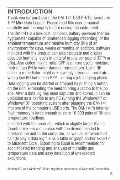
INTRODUCTIONThank you for purchasing the OM-141 USB RH/Temperature/ GPP Mini Data Logger. Please read this user’s manualcarefully and thoroughly before unsing the instrument.The OM-141 is a low-cost, compact, battery-powered thermo-hygrometer capable of unattended logging (recording) of theambient temperature and relative humidity (RH) of anenvironment for days, weeks or months. In addition, software included with the product can also calculate and displayabsolute humidity levels in units of grains per pound (GPP) org/kg. Also called mixing ratio, GPP is a more useful moisturemetric than RH to water damage remediators. Using RHalone, a remediator might unknowingly introduce moist air—with a low RH but a high GPP—during a job’s drying phase.Data logging can be started or stopped by pushing a button on the unit, eliminating the need to bring a laptop to the jobsite. After a data log has been captured and stored, it can beuploaded as a .txt file to any PC running the Windows®7 or Windows® XP operating system after plugging the OM-141into one of the computer’s USB ports. The OM-141’s internal flash memory is large enough to store 16,300 pairs of RH andtemperature readings.Included with the product—which is slightly larger than athumb drive—is a mini-disc with the drivers needed tointerface the unit to the computer, as well as software thatcan display a data log file as a table or graph and/or export itto Microsoft Excel. Exporting to Excel is recommended forsophisticated trending and analysis of humidity andtemperature data and easy detection of unexpectedexcursions.
3Windows® 7 and Windows® XP are registered trademarks of Microsoft Corporation.
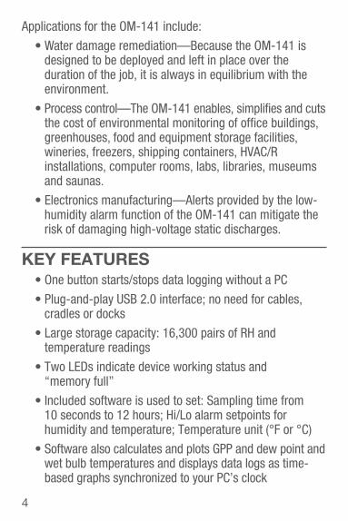
Applications for the OM-141 include:
Water damage remediation—Because the OM-141 isdesigned to be deployed and left in place over the duration of the job, it is always in equilibrium with theenvironment.
Process control—The OM-141 enables, simplifies and cutsthe cost of environmental monitoring of office buildings,greenhouses, food and equipment storage facilities,wineries, freezers, shipping containers, HVAC/Rinstallations, computer rooms, labs, libraries, museumsand saunas.
Electronics manufacturing—Alerts provided by the low-humidity alarm function of the OM-141 can mitigate therisk of damaging high-voltage static discharges.
KEY FEATURES One button starts/stops data logging without a PC
Plug-and-play USB 2.0 interface; no need for cables,cradles or docks
Large storage capacity: 16,300 pairs of RH andtemperature readings
Two LEDs indicate device working status and “memory full”
Included software is used to set: Sampling time from 10 seconds to 12 hours; Hi/Lo alarm setpoints forhumidity and temperature; Temperature unit (°F or °C)
Software also calculates and plots GPP and dew point andwet bulb temperatures and displays data logs as time-based graphs synchronized to your PC’s clock
4
One-click exporting of logs to Excel
Long battery life (up to one year)
Includes USB extension cable
One-year warranty
SAFETY INSTRUCTIONDo not use the OM-141 in the presence of flammable orexplosive gases.
WHAT’S IN THE BLISTER PACKThe OM-141 comes in a blister pack that also contains
One “1/2 AA” battery. Replacement batteries (Part no. OM-EL-BATT) are available from Omega
A disc with software drivers for Windows7 and Windows XP computers, the ELusb V1.21.2 program for capturing data logs and displaying them as curves, and a PDF ofthis user’s manual
A USB extension cable
A hard copy of this user’s manual (inside the fold-over card)
5
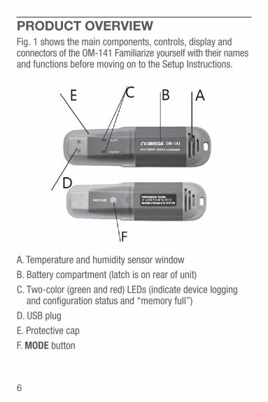
PRODUCT OVERVIEWFig. 1 shows the main components, controls, display andconnectors of the OM-141 Familiarize yourself with their namesand functions before moving on to the Setup Instructions.
A. Temperature and humidity sensor window
B. Battery compartment (latch is on rear of unit)
C. Two-color (green and red) LEDs (indicate device loggingand configuration status and “memory full”)
D. USB plug
E. Protective cap
F. MODE button
6
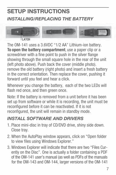
SETUP INSTRUCTIONSINSTALLING/REPLACING THE BATTERY
The OM-141 uses a 3.6VDC “1/2 AA” Lithium-ion battery. To open the battery compartment, use a paper clip or ascrewdriver with a fine point to push in the silver flangeshowing through the small square hole in the rear of the unit(left photo above). Push back the cover (middle photo).remove the old battery (right photo) and insert a fresh batteryin the correct orientation. Then replace the cover, pushing it forward until you feel and hear a click.
Whenever you change the battery, each of the two LEDs willflash red once, and then green once.
Note: If the battery is removed from a unit before it has beenset up from software or while it is recording, the unit must bereconfigured before it can be reactivated. If it is notreconfigured, the unit will remain in standby mode.
INSTALL SOFTWARE AND DRIVERS1. Place mini-disc in tray of CD/DVD drive, shiny side down.
Close tray.
2. When the AutoPlay window appears, click on “Open folder to view files using Windows Explorer.”
3. Windows Explorer will indicate that there are two “Files Cur- ently on the Disc”. One is actually a folder containing a PDF of the OM-141 user’s manual (as well as PDFs of the manualsfor the OM-143 and OM-144, larger versions of the OM-141
7

with LCDs). Copy the OM-141 manual to your computer’shard drive for permanent storage. The other file is a Windows Installer Package (.msi file) named “ELusb V1.21.2.msi”.Double-click its icon.
4. A window titled “Welcome to ELUsb Installation Wizard” will appear. Click Next to continue.
5. Within the Software License Agreement window that appears next, click the I agree (T) box.
6. The next three windows advise that the ELusb applicationwill be installed in your computer’s C:\Program Files foldersin a new subfolder named <ELusb>, and that shortcuts tothe program will be created on your desktop and QuickLaunch bar. If you want to install the software elsewhere,click Browse and choose another location. Within each window, after selecting either the default location or another location, click Next(N) to continue.
7. When the “Preparing to Install” window detailing thechanges to made appears, click Install (I) to continue.
8. Before the installation begins, a User Account Control window may appear and ask, “Do you want to allow[ELusb V1.21.2.msi] to make changes to this computer?” Click Yes to continue.
9. The ELUsb Setup Wizard will now install the program on your computer. On the next window that appears, click the Completed (F) box.
10. At the bottom of the Device Driver Installation Wizard that appears next, click Next to continue.
11. The next window to appear is a Windows Security window. Click on “Install this driver software anyway” tocontinue.
8
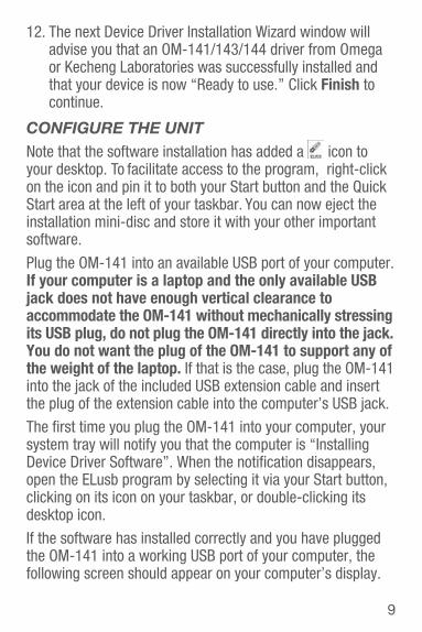
12. The next Device Driver Installation Wizard window will advise you that an OM-141/143/144 driver from Omegaor Kecheng Laboratories was successfully installed andthat your device is now “Ready to use.” Click Finish to continue.
CONFIGURE THE UNITNote that the software installation has added a icon toyour desktop. To facilitate access to the program, right-clickon the icon and pin it to both your Start button and the Quick Start area at the left of your taskbar. You can now eject the installation mini-disc and store it with your other importantsoftware.
Plug the OM-141 into an available USB port of your computer.If your computer is a laptop and the only available USBjack does not have enough vertical clearance to accommodate the OM-141 without mechanically stressing its USB plug, do not plug the OM-141 directly into the jack. You do not want the plug of the OM-141 to support any of the weight of the laptop. If that is the case, plug the OM-141 into the jack of the included USB extension cable and insert the plug of the extension cable into the computer’s USB jack.
The first time you plug the OM-141 into your computer, yoursystem tray will notify you that the computer is “Installing Device Driver Software”. When the notification disappears,open the ELusb program by selecting it via your Start button,clicking on its icon on your taskbar, or double-clicking itsdesktop icon.
If the software has installed correctly and you have pluggedthe OM-141 into a working USB port of your computer, thefollowing screen should appear on your computer’s display.
9
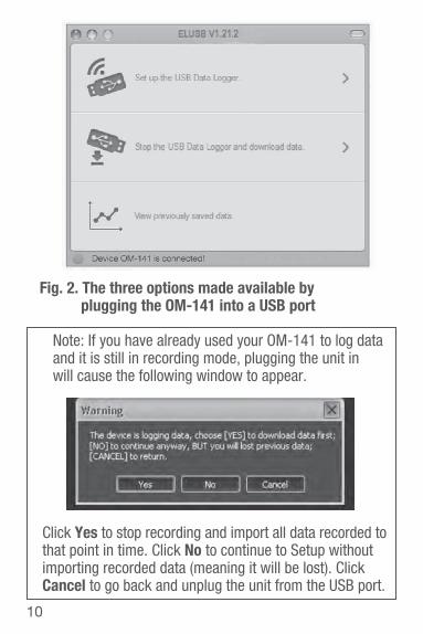
Note: If you have already used your OM-141 to log dataand it is still in recording mode, plugging the unit inwill cause the following window to appear.
Click Yes to stop recording and import all data recorded tothat point in time. Click No to continue to Setup withoutimporting recorded data (meaning it will be lost). ClickCancel to go back and unplug the unit from the USB port.
10
Fig. 2. The three options made available by plugging the OM-141 into a USB port
Device OM-141 is connected!
You can now use the software to “configure” your OM-141. Configuring the device means choosing four key parameters:
Sampling time—How often it makes and storeshumidity and temperature measurements.
Temperature unit—degrees Fahrenheit or Celsius (°F or °C).
High and low temperature alarm setpoints High and low humidity alarm setpoints
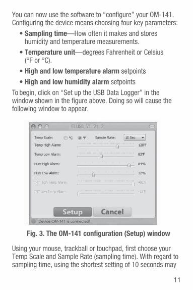
To begin, click on “Set up the USB Data Logger” in the window shown in the figure above. Doing so will cause thefollowing window to appear.
Using your mouse, trackball or touchpad, first choose yourTemp Scale and Sample Rate (sampling time). With regard tosampling time, using the shortest setting of 10 seconds may
11
Device HT08 is connected!
Fig. 3. The OM-141 configuration (Setup) window
result in too much essentially identical data being stored inmemory, potentially limiting its capacity to capture importantevents such as an unexpected excursion of temperature orhumidity. Conversely, using the longest sampling time settingof 12 hours will likely cause important events to goundetected.
If you are an experienced data logger, you already know howto choose the optimum sampling time for your application. Ifyou are a novice, pick a sampling time closer to the minimum sampling time than the maximum, on the assumption that theOM-141 probably has enough memory (16,300 pairs of RH antemperature readings) to store all the data you ask the meterto log—unless you use it to log data for months, rather thanweeks or days.
Be aware that if you do manage to fill up the OM-141’s memory (by logging for a very long time at a very short sampling time,for example), the device will simply stop recording. It will notcontinue recording by overwriting the oldest saved data withnew data.
If you wish, you can also drag the sliders shown in the figurto set high and low alarm setpoints for temperature andhumidity.
Once you have chosen your data logging parameters, clickSetup. A window will appear advising that “The device is set upsuccessfully.” Clicking Setup also synchronizes the OM-141’s internal clock with your computer’s clock, giving all data logsto be captured an absolute time reference.
You can now unplug the OM-141 from your computer’s USBport. The unit is in “standby mode, ready to begin logging data.
12
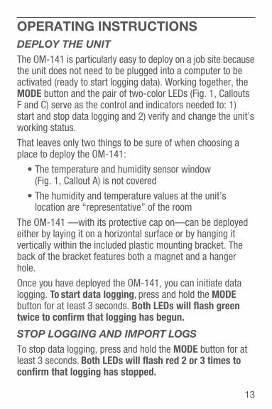
OPERATING INSTRUCTIONSDEPLOY THE UNITThe OM-141 is particularly easy to deploy on a job site becausethe unit does not need to be plugged into a computer to beactivated (ready to start logging data). Working together, theMODE button and the pair of two-color LEDs (Fig. 1, CalloutsF and C) serve as the control and indicators needed to: 1)start and stop data logging and 2) verify and change the unit’sworking status.
That leaves only two things to be sure of when choosing aplace to deploy the OM-141:
The temperature and humidity sensor window (Fig. 1, Callout A) is not covered
The humidity and temperature values at the unit’slocation are “representative” of the room
The OM-141 —with its protective cap on—can be deployedeither by laying it on a horizontal surface or by hanging itvertically within the included plastic mounting bracket. Theback of the bracket features both a magnet and a hangerhole.
Once you have deployed the OM-141, you can initiate datalogging. To start data logging, press and hold the MODE button for at least 3 seconds. Both LEDs will flash greentwice to confirm that logging has begun.
STOP LOGGING AND IMPORT LOGSTo stop data logging, press and hold the MODE button for at least 3 seconds. Both LEDs will flash red 2 or 3 times toconfirm that logging has stopped.
13
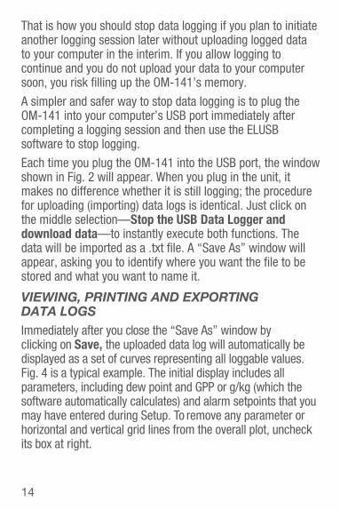
That is how you should stop data logging if you plan to initiateanother logging session later without uploading logged datato your computer in the interim. If you allow logging tocontinue and you do not upload your data to your computersoon, you risk filling up the OM-141’s memory.
A simpler and safer way to stop data logging is to plug theOM-141 into your computer’s USB port immediately after completing a logging session and then use the ELUSBsoftware to stop logging.
Each time you plug the OM-141 into the USB port, the windowshown in Fig. 2 will appear. When you plug in the unit, itmakes no difference whether it is still logging; the procedurefor uploading (importing) data logs is identical. Just click onthe middle selection—Stop the USB Data Logger anddownload data—to instantly execute both functions. Thedata will be imported as a .txt file. A “Save As” window will appear, asking you to identify where you want the file to bestored and what you want to name it.
VIEWING, PRINTING AND EXPORTINGDATA LOGSImmediately after you close the “Save As” window by clicking on Save, the uploaded data log will automatically be displayed as a set of curves representing all loggable values.Fig. 4 is a typical example. The initial display includes all parameters, including dew point and GPP or g/kg (which thesoftware automatically calculates) and alarm setpoints that youmay have entered during Setup. To remove any parameter orhorizontal and vertical grid lines from the overall plot, uncheckits box at right.
14
15
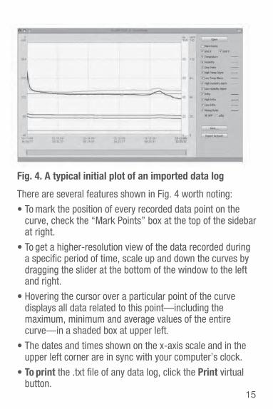
Fig. 4. A typical initial plot of an imported data log
There are several features shown in Fig. 4 worth noting:
To mark the position of every recorded data point on thecurve, check the “Mark Points” box at the top of the sidebar at right.
To get a higher-resolution view of the data recorded duringa specific period of time, scale up and down the curves bydragging the slider at the bottom of the window to the left and right.
Hovering the cursor over a particular point of the curvedisplays all data related to this point—including themaximum, minimum and average values of the entirecurve—in a shaded box at upper left.
The dates and times shown on the x-axis scale and in theupper left corner are in sync with your computer’s clock.
To print the .txt file of any data log, click the Print virtual button.
To open a previously saved data log, click the Open button. This function is also available as the “View previously saved data” option shown in Fig. 2.
To export a file to Excel for advanced trending andanalysis, click the Export to Excel button.
OTHER INDICATIONSAs mentioned earlier, the MODE button and the pair of two- color LEDs work together to indicate the current workingstatus of the OM-141. For example, the MODE button can beused to confirm whether or not the unit has been configured(activated) using the software’s Setup window (see Fig. 3):
If the unit is ready to log data, a quick press of theMODE button will cause both LEDs to flash green once.
If the OM-141 needs to be configured, the two LEDswill alternately flash red and green twice.
If a quick press of the MODE button causes both LEDs to flash red once, logging has been stopped because the memory is full.
During data logging, the pair of two-color LEDs will flashgreen or red to indicate whether measured humidity antemperature values are within or outside the band betweenthe preset low and high alarms:
The LEDs will alternately flash green one time each if the values of both parameters have not exceeded their setpoints.
The LEDs will alternately flash red one time each if the value of either parameters has exceeded its setpoints.
16
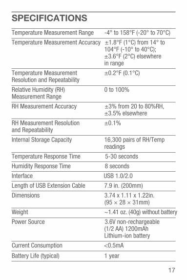
SPECIFICATIONSTemperature Measurement Range -4° to 158°F (-20° to 70°C)
Temperature Measurement Accuracy ±1.8°F (1°C) from 14° to104°F (-10° to 40°C); ±3.6°F (2°C) elsewhere in range
Temperature Measurement ±0.2°F (0.1°C)Resolution and Repeatability
Relative Humidity (RH) 0 to 100%Measurement Range
RH Measurement Accuracy ±3% from 20 to 80%RH,±3.5% elsewhere
RH Measurement Resolution ±0.1%and Repeatability
Internal Storage Capacity 16,300 pairs of RH/Tempreadings
Temperature Response Time 5-30 seconds
Humidity Response Time 8 seconds
Interface USB 1.0/2.0
Length of USB Extension Cable 7.9 in. (200mm)
Dimensions 3.74 x 1.11 x 1.22in. (95 × 28 × 31mm)
Weight ~1.41 oz. (40g) without battery
Power Source 3.6V non-rechargeable (1/2 AA) 1200mAh Lithium-ion battery
Current Consumption <0.5mA
Battery Life (typical) 1 year
17
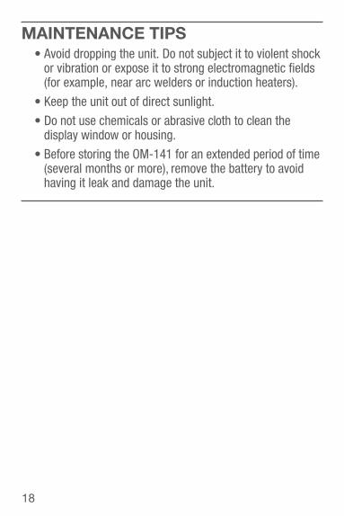
MAINTENANCE TIPS Avoid dropping the unit. Do not subject it to violent shockor vibration or expose it to strong electromagnetic fields(for example, near arc welders or induction heaters).
Keep the unit out of direct sunlight.
Do not use chemicals or abrasive cloth to clean the display window or housing.
Before storing the OM-141 for an extended period of time(several months or more), remove the battery to avoidhaving it leak and damage the unit.
18

FOR WARRANTY RETURNS, please have the following information available BEFORE contacting OMEGA:1. Purchase Order number under which the
product was PURCHASED,2. Model and serial number of the product
under warranty, and3. Repair instructions and/or specific
problems relative to the product.
FOR NON-WARRANTY REPAIRS, consult OMEGA for current repair charges. Have the following information available BEFORE contacting OMEGA:1. Purchase Order number to cover the COST
of the repair,2. Model and serial number of the product, and3. Repair instructions and/or specific problems
relative to the product.
OMEGA’s policy is to make running changes, not model changes, whenever an improvement is possible. This affords our customers the latest in technology and engineering.OMEGA is a registered trademark of OMEGA ENGINEERING, INC.© Copyright 2016 OMEGA ENGINEERING, INC. All rights reserved. This document may not be copied, photocopied, reproduced, translated, or reduced to any electronic medium or machine-readable form, in whole or in part, without the prior written consent of OMEGA ENGINEERING, INC.
WARRANTY/DISCLAIMEROMEGA ENGINEERING, INC. warrants this unit to be free of defects in materials and workmanship for a period of 13 months from date of purchase. OMEGA’s Warranty adds an additional one (1) month grace period to the normal one (1) year product warranty to cover handling and shipping time. This ensures that OMEGA’s customers receive maximum coverage on each product. If the unit malfunctions, it must be returned to the factory for evaluation. OMEGA’s Customer Service Department will issue an Authorized Return (AR) number immediately upon phone or written request. Upon examination by OMEGA, if the unit is found to be defective, it will be repaired or replaced at no charge. OMEGA’s WARRANTY does not apply to defects resulting from any action of the purchaser, including but not limited to mishandling, improper interfacing, operation outside of design limits, improper repair, or unauthorized modification. This WARRANTY is VOID if the unit shows evidence of having been tampered with or shows evidence of having been damaged as a result of excessive corrosion; or current, heat, moisture or vibration; improper specification; misapplication; misuse or other operating conditions outside of OMEGA’s control. Components in which wear is not warranted, include but are not limited to contact points, fuses, and triacs.OMEGA is pleased to offer suggestions on the use of its various products. However, OMEGA neither assumes responsibility for any omissions or errors nor assumes liability for any damages that result from the use of its products in accordance with information provided by OMEGA, either verbal or written. OMEGA warrants only that the parts manufactured by the company will be as specified and free of defects. OMEGA MAKES NO OTHER WARRANTIES OR REPRESENTATIONS OF ANY KIND WHATSOEVER, EXPRESSED OR IMPLIED, EXCEPT THAT OF TITLE, AND ALL IMPLIED WARRANTIES INCLUDING ANY WARRANTY OF MERCHANTABILITY AND FITNESS FOR A PARTICULAR PURPOSE ARE HEREBY DISCLAIMED. LIMITATION OF LIABILITY: The remedies of purchaser set forth herein are exclusive, and the total liability of OMEGA with respect to this order, whether based on contract, warranty, negligence, indemnification, strict liability or otherwise, shall not exceed the purchase price of the component upon which liability is based. In no event shall OMEGA be liable for consequential, incidental or special damages.CONDITIONS: Equipment sold by OMEGA is not intended to be used, nor shall it be used: (1) as a “Basic Component” under 10 CFR 21 (NRC), used in or with any nuclear installation or activity; or (2) in medical applications or used on humans. Should any Product(s) be used in or with any nuclear installation or activity, medical application, used on humans, or misused in any way, OMEGA assumes no responsibility as set forth in our basic WARRANTY/DISCLAIMER language, and, additionally, purchaser will indemnify OMEGA and hold OMEGA harmless from any liability or damage whatsoever arising out of the use of the Product(s) in such a manner.
RETURN REQUESTS/ INQUIRIESDirect all warranty and repair requests/inquiries to the OMEGA Customer Service Department. BEFORE RETURNING ANY PRODUCT(S) TO OMEGA, PURCHASER MUST OBTAIN AN AUTHORIZED RETURN (AR) NUMBER FROM OMEGA’S CUSTOMER SERVICE DEPARTMENT (IN ORDER TO AVOID PROCESSING DELAYS). The assigned AR number should then be marked on the outside of the return package and on any correspondence. The purchaser is responsible for shipping charges, freight, insurance and proper packaging to prevent breakage in transit.

M5564/0416
Where Do I Find Everything I Need for Process Measurement and Control?
OMEGA…Of Course!Shop online at omega.com SM
TEMPERATUREMU Thermocouple, RTD & Thermistor
Probes, Connectors, Panels & Assemblies
MU Wire: Thermocouple, RTD & Thermistor
MU Calibrators & Ice Point ReferencesMU Recorders, Controllers & Process
MonitorsMU Infrared Pyrometers
PRESSURE, STRAIN ANDFORCEMU Transducers & Strain GagesMU Load Cells & Pressure GagesMU Displacement TransducersMU Instrumentation & Accessories
FLOW/LEVELMU Rotameters, Gas Mass Flowmeters
& Flow ComputersMU Air Velocity IndicatorsMU Turbine/Paddlewheel SystemsMU Totalizers & Batch Controllers
pH/CONDUCTIVITYMU pH Electrodes, Testers &
AccessoriesMU Benchtop/Laboratory MetersMU Controllers, Calibrators, Simulators
& PumpsMU Industrial pH & Conductivity
Equipment
DATA ACQUISITIONMU Data Acquisition & Engineering
SoftwareMU Communications-Based Acquisition
SystemsMU Plug-in Cards for Apple, IBM &
CompatiblesMU Data Logging SystemsMU Recorders, Printers & Plotters
HEATERSMU Heating CableMU Cartridge & Strip HeatersMU Immersion & Band HeatersMU Flexible HeatersMU Laboratory Heaters
ENVIRONMENTALMONITORING AND CONTROLMU Metering & Control
InstrumentationMU RefractometersMU Pumps & TubingMU Air, Soil & Water MonitorsMU Industrial Water & Wastewater
TreatmentMU pH, Conductivity & Dissolved
Oxygen Instruments