Embed Size (px)
Citation preview
OIML R 49-2Water meters intended for the metering of cold potable
water and hot water meters
TEST METHODS
APEC/APLMF Training Coursesin Legal Metrology
September 23 – 26, 2008Hanoi, Vietnam
Asia-PacificLegal Metrology
Forum
SCOPE
Applicable to type evaluation and initial verification testing
Applicable to cold potable and hot water
Sets out details of the test program, principles, equipment and procedures to be used
Applicable to complete meters or selected components
OIML R 49-2
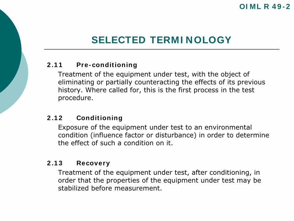
SELECTED TERMINOLOGY
2.11 Pre-conditioningTreatment of the equipment under test, with the object of eliminating or partially counteracting the effects of its previous history. Where called for, this is the first process in the test procedure.
2.12 ConditioningExposure of the equipment under test to an environmental condition (influence factor or disturbance) in order to determine the effect of such a condition on it.
2.13 RecoveryTreatment of the equipment under test, after conditioning, in order that the properties of the equipment under test may be stabilized before measurement.
OIML R 49-2
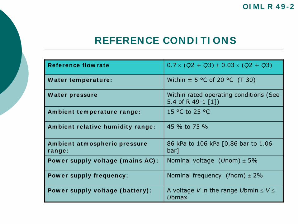
REFERENCE CONDITIONS
Reference flowrate 0.7 × (Q2 + Q3) ± 0.03 × (Q2 + Q3)
Water temperature: Within ± 5 °C of 20 °C (T 30)
Water pressure Within rated operating conditions (See 5.4 of R 49-1 [1])
Ambient temperature range: 15 °C to 25 °C
Ambient relative humidity range: 45 % to 75 %
Ambient atmospheric pressure range:
86 kPa to 106 kPa [0.86 bar to 1.06 bar]
Power supply voltage (mains AC): Nominal voltage (Unom) ± 5%
Power supply frequency: Nominal frequency (fnom) ± 2%
Power supply voltage (battery): A voltage V in the range Ubmin ≤ V ≤Ubmax
OIML R 49-2

REFERENCE CONDITIONS
During each test:
The temperature shall not vary by more than 5 °C
The relative humidity shall not vary by more than 10 %
OIML R 49-2
PERFORMANCE TESTSGeneral Requirements
Water:
Shall be used for all testsShall be public potable water or equivalentWater shall be free of substances that can damage the meterShall not contain bubbles
Test Equipment:
Shall be designed, constructed and used to ensure that reference conditions are met
Shall be subjected to periodic inter-comparisons between test rigs in accordance with OIML International Document D7
OIML R 49-2
PERFORMANCE TESTSGeneral Requirements (cont.)
Group Testing:
Meters can be tested either individually or in groups
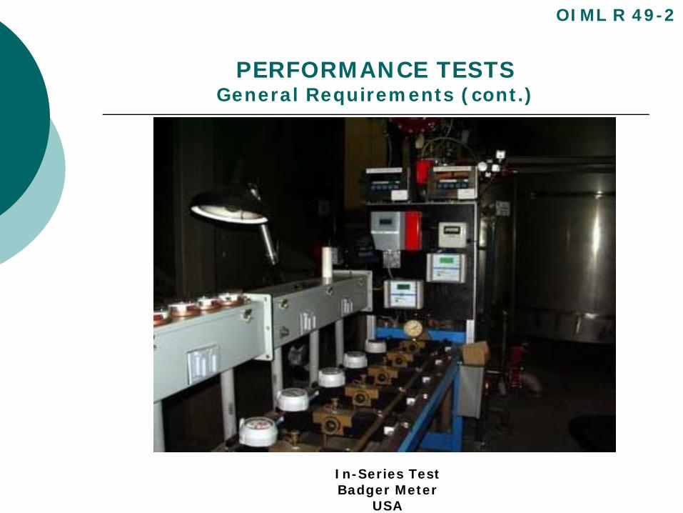
When meters are tested in series, the pressure at the exit of each meter shall be sufficient to prevent cavitation
Location:
The environment (test facility) chosen for meter tests shall be in accordance with the principles elaborated in OIML publication G 13 Planning of metrology and testing laboratories
Shall be free from disturbing influences (for example, ambient temperature, vibration)
OIML R 49-2
PERFORMANCE TESTSGeneral Requirements (cont.)
OIML R 49-2
In-Series TestBadger Meter
USA
PERFORMANCE TESTS
Tests Applicable to All Meters:
Static pressureIntrinsic Error (of indication) and Meter OrientationWater temperatureWater pressureFlow reversalPressure lossFlow disturbanceDiscontinuous flow enduranceContinuous flow endurance test
OIML R 49-2
STATIC PRESSURE TEST
Object of the test:
To verify that the water meter can withstand the specified hydraulic test pressure for the specified time without leakage or damage.
OIML R 49-2
STATIC PRESSURE TEST
Test procedure (In-line meters):
Caution to only increase and decrease the pressure gradually without pressure surges.
Increase the hydraulic pressure to 1.6 times the maximum admissible pressure (MAP) of the meter, hold it for 15 minutes.
Examine the meters for physical damage, for external leaks and for leaks into the indicating device.
Increase the hydraulic pressure to twice the MAP, hold for 1min.
Examine the meters for physical damage and leaks
Complete test report 5.1 in R 49-3.oiml r49-3 Static pressure test.doc
OIML R 49-2
STATIC PRESSURE TEST
Acceptance criteria:
There shall be no leakage from the meter or leakage into the indicating device, or physical damage
OIML R 49-2
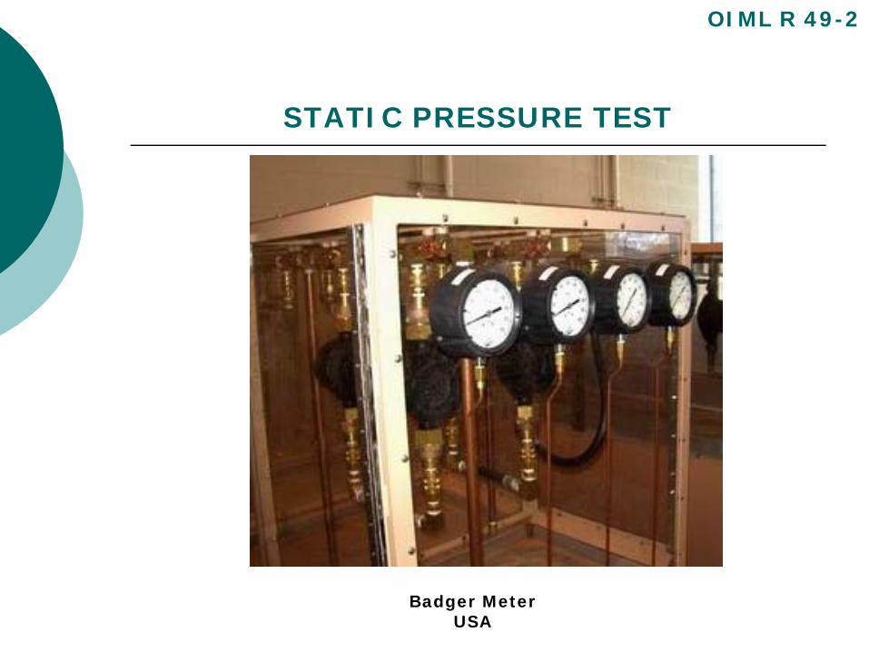
STATIC PRESSURE TEST
OIML R 49-2
Badger MeterUSA
INTRINSIC ERROR (of indication) TEST
Object of the test:
To determine the intrinsic errors (of indication) of the water
meter.
OIML R 49-2
INTRINSIC ERROR (of indication) TEST
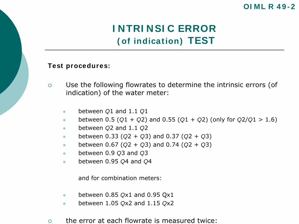
Test procedures:
Use the following flowrates to determine the intrinsic errors (of indication) of the water meter:
between Q1 and 1.1 Q1between 0.5 (Q1 + Q2) and 0.55 (Q1 + Q2) (only for Q2/Q1 > 1.6)between Q2 and 1.1 Q2between 0.33 (Q2 + Q3) and 0.37 (Q2 + Q3)between 0.67 (Q2 + Q3) and 0.74 (Q2 + Q3)between 0.9 Q3 and Q3between 0.95 Q4 and Q4
and for combination meters:
between 0.85 Qx1 and 0.95 Qx1between 1.05 Qx2 and 1.15 Qx2
the error at each flowrate is measured twice:
OIML R 49-2
INTRINSIC ERROR (of indication) TEST
Test procedures (cont.):
During a test hold all other influence factors at reference conditions
Measure the errors (of indication) at other flowrates if the shape of the error curve indicates that the mpe may be exceeded
Calculate the relative error (of indication) for each flowrate
Complete test report R 49-3, 5.3.oiml r49-3 intrinsic error.doc
OIML R 49-2
INTRINSIC ERROR (of indication)TEST
Acceptance criteria:
Errors (of indication) shall not exceed the applicable mpe for each test run. Class 2 MPE.ppt
If the error observed on one or more meters is greater than the maximum permissible error at one flowrate only the test at that flowrate shall be repeated. flowratesOIML 49-2.ppt
The test shall be declared satisfactory if two out of the three results lie within the maximum permissible error and the arithmetic mean of the results for the three tests at that flowrate is less than or equal to the maximum permissible error.
If all the relative errors (of indication) of the water meter have the same sign, at least one of the errors shall not exceed one half of the maximum permissible error.
In all cases this requirement shall be applied equitably with respect to the water supplier and the consumer
OIML R 49-2
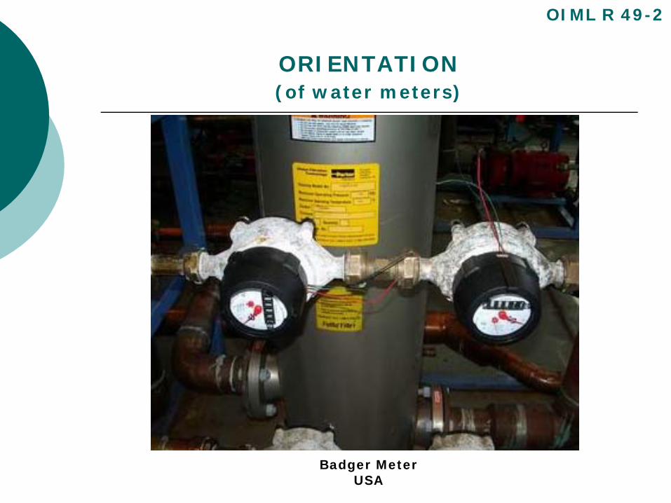
ORIENTATION (of water meters)
If the meters are marked ‘H’ mount the connecting pipework with the flow axis in the horizontal plane during the test.
If the meters are marked ‘V’ mount the connecting pipework with the flow axis in the vertical plane during the test.
If the meters are not marked ‘H’ or ‘V’,
at least one meter from the sample shall be mounted with the flow axis vertical, with flow direction from bottom to top
at least one meter from the sample shall be mounted with the flow axis vertical, with flow direction from top to bottom
at least one meter from the sample shall be mounted with the flow axis at an intermediate angle to the vertical and horizontal
the remaining meters from the sample shall be mounted with the flow axis horizontal.
OIML R 49-2
ORIENTATION (of water meters)
OIML R 49-2
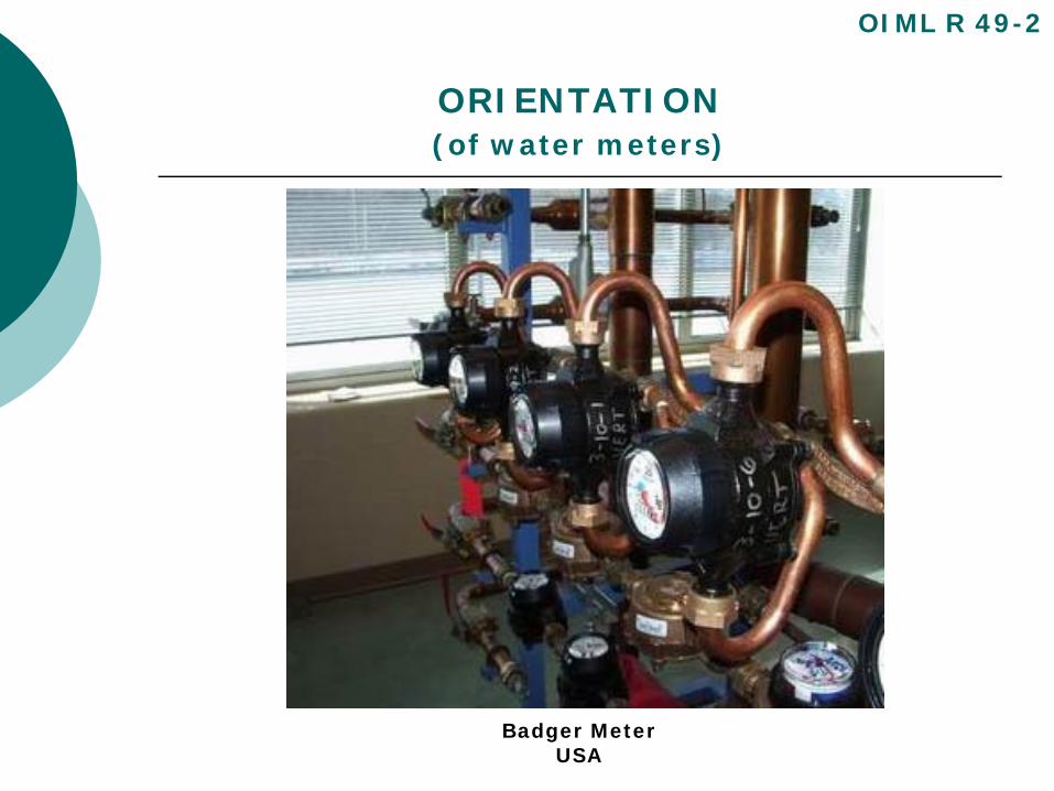
Badger MeterUSA
ORIENTATION (of water meters)
OIML R 49-2
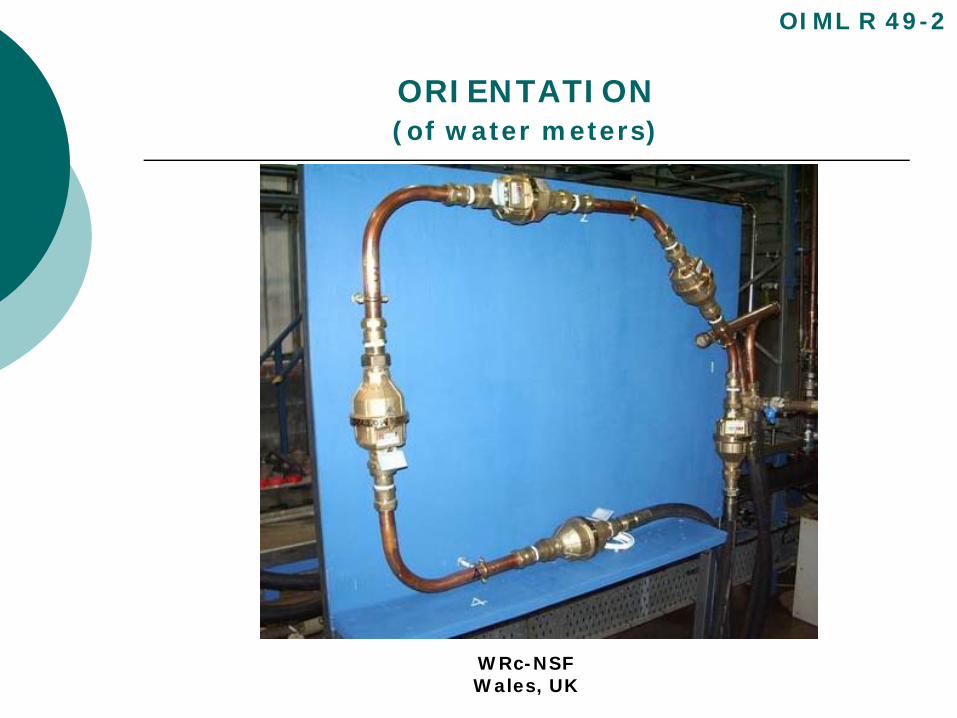
WRc-NSFWales, UK
ORIENTATION (of water meters)
Where the meters have an indicating device which is integral with the body of the meter, at least one of the horizontally mounted meters shall be oriented with the indicating device positioned at the side and the remaining meters shall be oriented with the indicating device positioned at the top.
The tolerance on the position of the flow axis for all meters, whether horizontal, vertically or at an intermediate angle, shall be ± 5°.
OIML R 49-2
ORIENTATION (of water meters)
OIML R 49-2
Badger MeterUSA
WATER TEMPERATURE TEST
Object of the test:
To measure the effects of water temperature on the errors (of indication) of the meter.
OIML R 49-2
WATER TEMPERATURE TEST
Test procedure:
Measure the error (of indication) of at least one meter at the flowrate Q2 with the inlet temperatures held at 10 °C ± 5 °C. All other influence factors maintained at reference conditions.
Measure the error (of indication) of at least one meter at the flowrate Q2 with the inlet temperatures held at the maximum admissible temperature (MAT) (Table 1, R 49-1) of the meter with a tolerance of +0 °C, – 5 °C and all other influence factors maintained at reference conditions.
Calculate the relative error (of indication) for each inlet water temperature in accordance with Annex B.
Complete test report R 49-3, 5.4.
OIML R 49-2
WATER TEMPERATURE TEST
Acceptance criteria:
The relative error (of indication) of the meter shall not exceed the applicable maximum permissible error (mpe).
Class 2, T30 meter @ Q2, mpe = ± 2%
OIML R 49-2
WATER PRESSURE TEST
Object of the test:
To measure the effects of internal water pressure on the errors (of indication) of the meter.
OIML R 49-2
WATER PRESSURE TEST
Test procedure:
Measure the error (of indication) of at least one meter at a flowrate of Q2 with the inlet pressure held firstly at 0.03 MPa (0.3 bar) ± 5 % and then at the maximum admissible pressure (MAP) (+ 0, – 10 %).
During each test, all other influence factors shall be maintained at reference conditions.
Calculate the relative error (of indication) for each inlet water pressure.
Complete test report R 49-3, 5.5.
OIML R 49-2
WATER PRESSURE TEST
Acceptance criteria:
The relative error (of indication) of the meter shall not exceed the applicable maximum permissible error (mpe).
Class 2, T30 meter @ Q2, mpe = ± 2%
OIML R 49-2
FLOW REVERSAL TEST
Object of the test
To verify that the meter satisfies the requirement of 3.2.6 in R 49-1 when flow reversals occur.reverse flow OIML R 49-1.ppt
OIML R 49-2
FLOW REVERSAL TEST
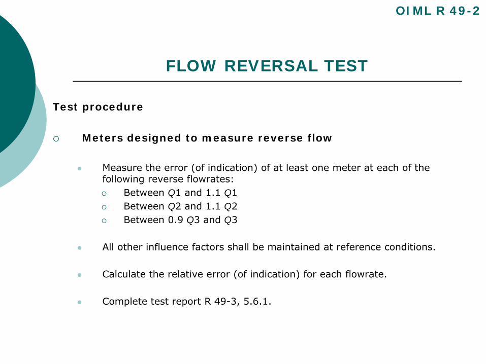
Test procedure
Meters designed to measure reverse flow
Measure the error (of indication) of at least one meter at each of the following reverse flowrates:
Between Q1 and 1.1 Q1Between Q2 and 1.1 Q2Between 0.9 Q3 and Q3
All other influence factors shall be maintained at reference conditions.
Calculate the relative error (of indication) for each flowrate.
Complete test report R 49-3, 5.6.1.
OIML R 49-2
FLOW REVERSAL TEST
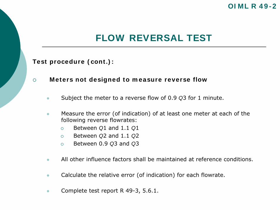
Test procedure (cont.):
Meters not designed to measure reverse flow
Subject the meter to a reverse flow of 0.9 Q3 for 1 minute.
Measure the error (of indication) of at least one meter at each of the following reverse flowrates:
Between Q1 and 1.1 Q1Between Q2 and 1.1 Q2Between 0.9 Q3 and Q3
All other influence factors shall be maintained at reference conditions.
Calculate the relative error (of indication) for each flowrate.
Complete test report R 49-3, 5.6.1.
OIML R 49-2
FLOW REVERSAL TEST
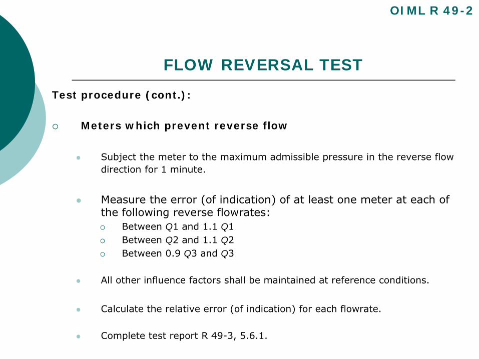
Test procedure (cont.):
Meters which prevent reverse flow
Subject the meter to the maximum admissible pressure in the reverse flow direction for 1 minute.
Measure the error (of indication) of at least one meter at each of the following reverse flowrates:
Between Q1 and 1.1 Q1Between Q2 and 1.1 Q2Between 0.9 Q3 and Q3
All other influence factors shall be maintained at reference conditions.
Calculate the relative error (of indication) for each flowrate.
Complete test report R 49-3, 5.6.1.
OIML R 49-2
FLOW REVERSAL TEST
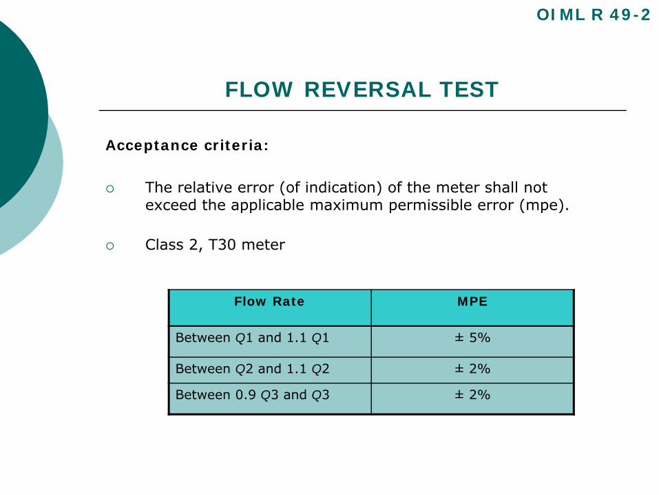
Acceptance criteria:
The relative error (of indication) of the meter shall not exceed the applicable maximum permissible error (mpe).
Class 2, T30 meter
OIML R 49-2
Flow Rate MPE
Between Q1 and 1.1 Q1 ± 5%
Between Q2 and 1.1 Q2 ± 2%
Between 0.9 Q3 and Q3 ± 2%
PRESSURE LOSS TEST
Object of the test:
To determine the maximum pressure loss through the watermeter at any flowrate between Q1 and Q3. To verify themaximum pressure loss is less than 0.063 MPa (0.63 bar).
pressure loss definition OIML R 49-1.ppt
OIML R 49-2
PRESSURE LOSS TEST
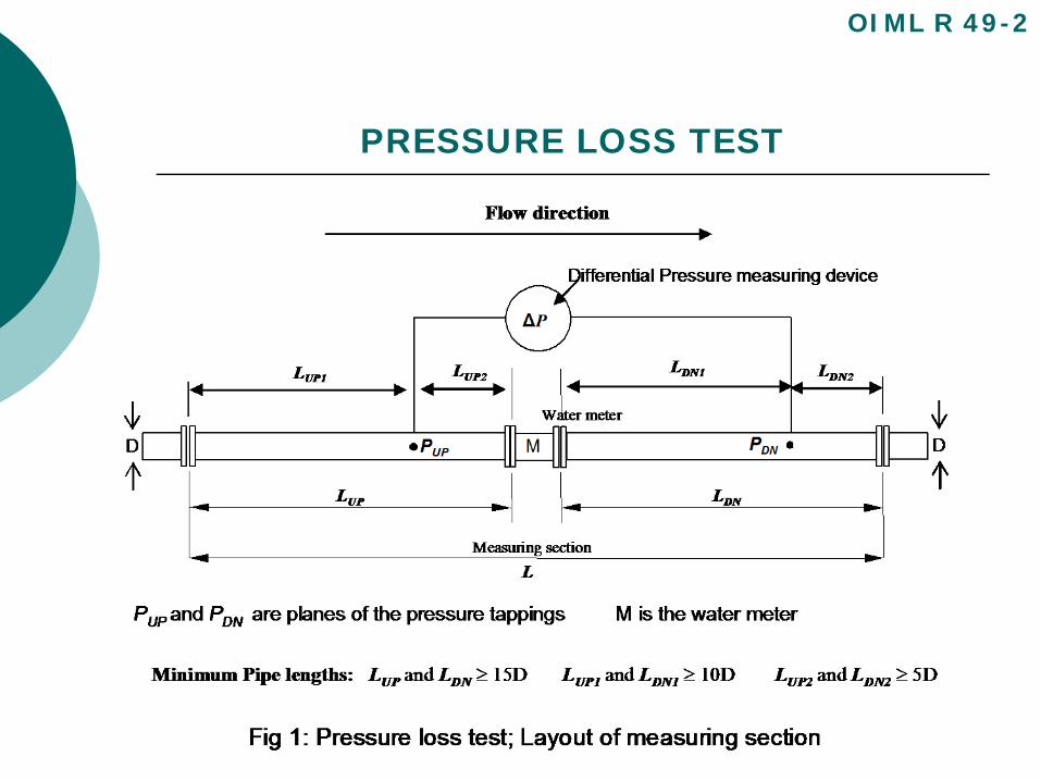
Test procedure:
Meter is placed in test rig
Vary flow between Q1 and Q3 and monitor differential pressure
Find the flowrate (Qt) showing the largest pressure loss
Record Qt, maximum pressure loss, and water temperature. Normally will be found to be equal to Q3
The static pressure downstream of the meter under test shall be at least 100 kPa to avoid cavitation or air release
Complete test report R 49-3, 5.7
OIML R 49-2
PRESSURE LOSS TEST
OIML R 49-2
PRESSURE LOSS TEST
OIML R 49-2
PRESSURE LOSS TEST
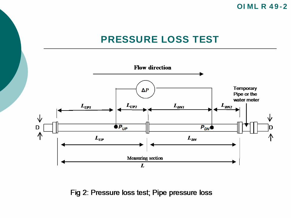
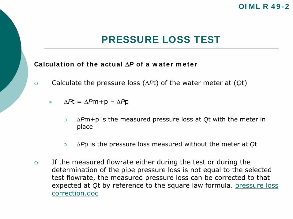
Calculation of the actual ΔP of a water meter
Calculate the pressure loss (ΔPt) of the water meter at (Qt)
ΔPt = ΔPm+p – ΔPp
ΔPm+p is the measured pressure loss at Qt with the meter in place
ΔPp is the pressure loss measured without the meter at Qt
If the measured flowrate either during the test or during the determination of the pipe pressure loss is not equal to the selected test flowrate, the measured pressure loss can be corrected to that expected at Qt by reference to the square law formula. pressure loss correction.doc
OIML R 49-2

PRESSURE LOSS TEST
Acceptance criteria:
The pressure loss of the meter shall not exceed 0.063 MPa (0.63 bar) at any flowrate between Q1 and Q3 inclusive.
OIML R 49-2
FLOW DISTURBANCE TEST
Object of the test:
To verify that the meter complies with the requirements of 5.3.4 in R 49-1
The effects on the error (of indication) of a water meter, of the presence of specified, common types of disturbed flow upstream and downstream of the meter are measured.
OIML R 49-2
FLOW DISTURBANCE TEST
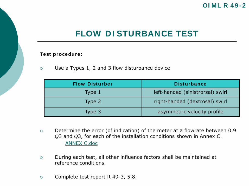
Test procedure:
Use a Types 1, 2 and 3 flow disturbance device
Determine the error (of indication) of the meter at a flowrate between 0.9 Q3 and Q3, for each of the installation conditions shown in Annex C.
ANNEX C.doc
During each test, all other influence factors shall be maintained at reference conditions.
Complete test report R 49-3, 5.8.
OIML R 49-2
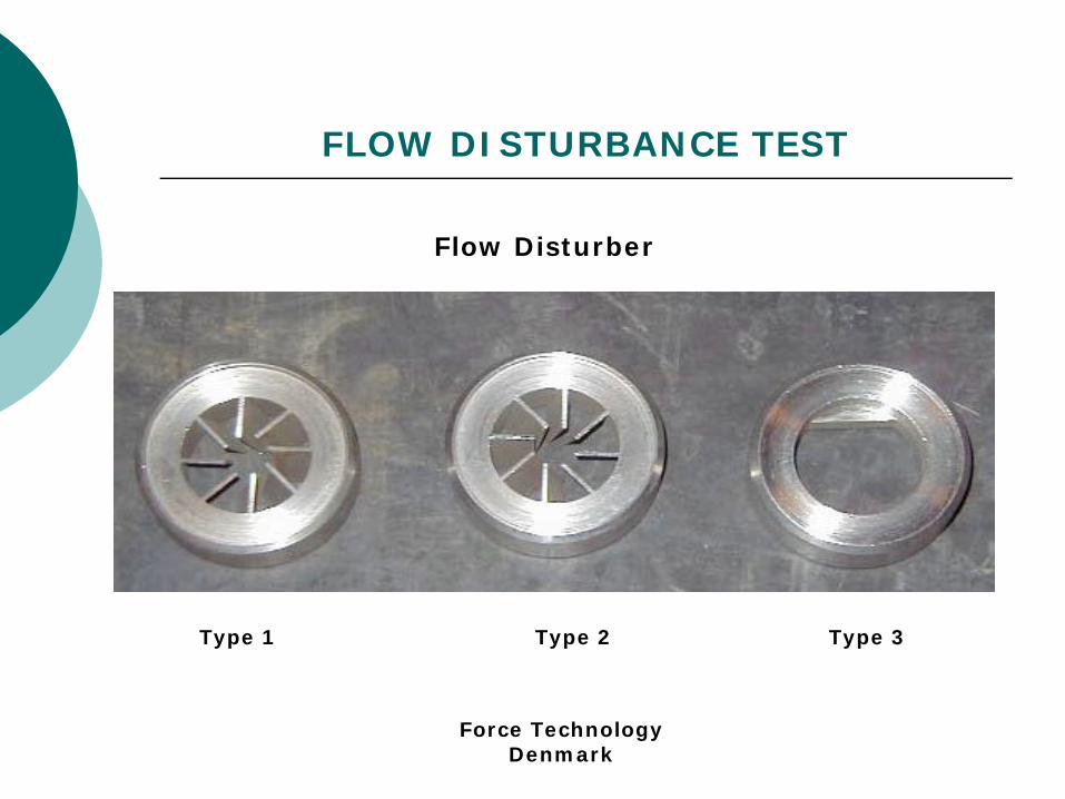
Flow Disturber Disturbance
Type 1 left-handed (sinistrorsal) swirl
Type 2 right-handed (dextrosal) swirl
Type 3 asymmetric velocity profile
FLOW DISTURBANCE TEST
Type 1 Type 2 Type 3
Flow Disturber
Force TechnologyDenmark
FLOW DISTURBANCE TEST
Test procedure:
Additional Requirements:
Additional Requirements FLow.doc
OIML R 49-2
FLOW DISTURBANCE TEST
Acceptance criteria:
The relative error (of indication) of the meter shall not exceed the applicable maximum permissible error for any of the flow disturbance tests.
OIML R 49-2
ENDURANCE TEST
Endurance test:Test intended to verify whether the water meter is able to maintain its performance characteristics over a period of use.
Types:Discontinuous
Continuous
Applications:Endurance Tests:
DISCONTINUOUS ENDURANCE TEST
Object of the test:
To verify that the water meter is durable when subjected to cyclic flow conditions.
This test is applied only to meters with Q3 ≤ 16 m3/h.
The meter is subjected to a specified number of starting and stopping flowrate cycles.
Each cycle is of a short duration.
The constant test flowrate phase of each cycle is kept at the specified flowrate (ex. Q3).
OIML R 49-2
DISCONTINUOUS ENDURANCE TEST
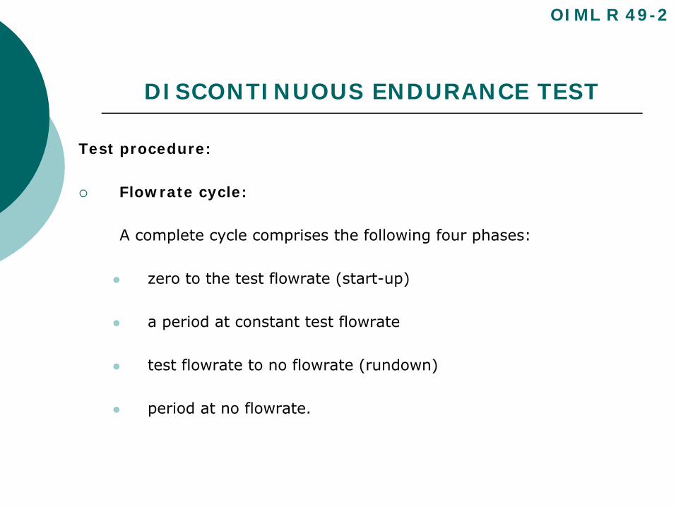
Test procedure:
Flowrate cycle:
A complete cycle comprises the following four phases:
zero to the test flowrate (start-up)
a period at constant test flowrate
test flowrate to no flowrate (rundown)
period at no flowrate.
OIML R 49-2
DISCONTINUOUS ENDURANCE TEST
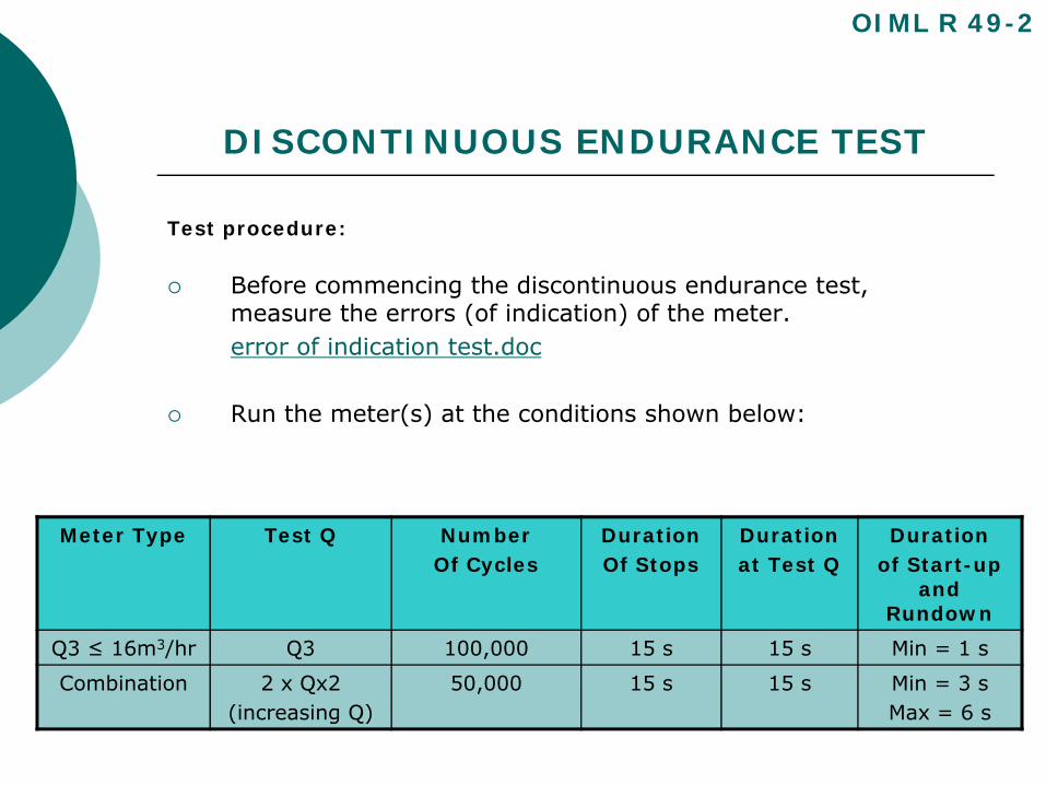
Test procedure:
Before commencing the discontinuous endurance test, measure the errors (of indication) of the meter.error of indication test.doc
Run the meter(s) at the conditions shown below:
OIML R 49-2
Meter Type Test Q NumberOf Cycles
Duration Of Stops
Durationat Test Q
Durationof Start-up
and Rundown
Q3 ≤ 16m3/hr Q3 100,000 15 s 15 s Min = 1 s
Combination 2 x Qx2(increasing Q)
50,000 15 s 15 s Min = 3 sMax = 6 s
DISCONTINUOUS ENDURANCE TEST
Test procedure cont:
Following the discontinuous endurance test, measure the final errors (of indication).
Calculate the final relative error (of indication) for each flowrate.
For each flowrate, subtract the value of the intrinsic error (of indication) obtained before the test from the error (of indication) obtained after the test.
Complete test report R 49-3, 5.9.1.
OIML R 49-2
DISCONTINUOUS ENDURANCE TEST
OIML R 49-2
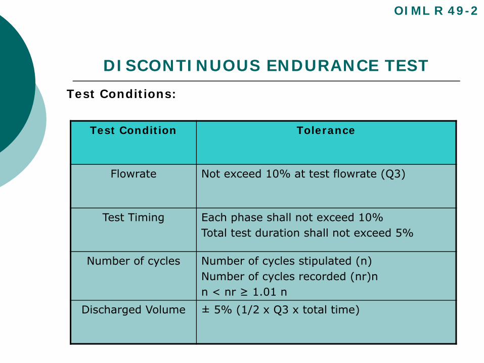
Test Conditions:
Test Condition Tolerance
Flowrate Not exceed 10% at test flowrate (Q3)
Test Timing Each phase shall not exceed 10%Total test duration shall not exceed 5%
Number of cycles Number of cycles stipulated (n)Number of cycles recorded (nr)nn < nr ≥ 1.01 n
Discharged Volume ± 5% (1/2 x Q3 x total time)
DISCONTINUOUS ENDURANCE TEST
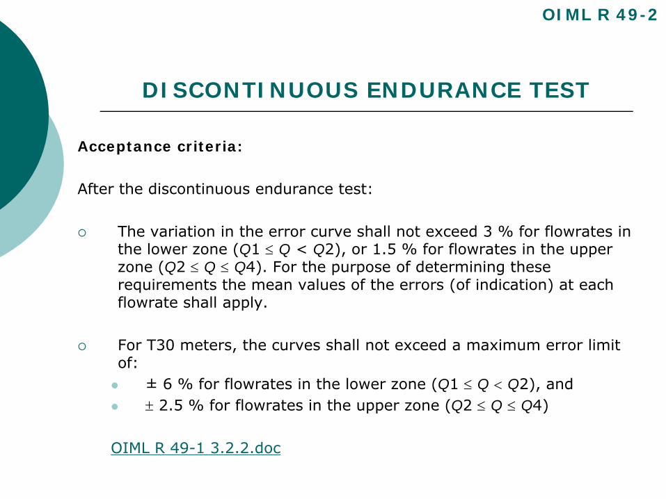
Acceptance criteria:
After the discontinuous endurance test:
The variation in the error curve shall not exceed 3 % for flowrates in the lower zone (Q1 ≤ Q < Q2), or 1.5 % for flowrates in the upper zone (Q2 ≤ Q ≤ Q4). For the purpose of determining these requirements the mean values of the errors (of indication) at each flowrate shall apply.
For T30 meters, the curves shall not exceed a maximum error limit of:
± 6 % for flowrates in the lower zone (Q1 ≤ Q < Q2), and± 2.5 % for flowrates in the upper zone (Q2 ≤ Q ≤ Q4)
OIML R 49-1 3.2.2.doc
OIML R 49-2
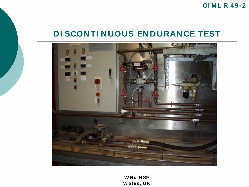
DISCONTINUOUS ENDURANCE TEST
OIML R 49-2
WRc-NSFWales, UK
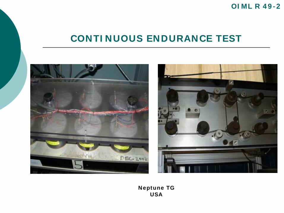
CONTINUOUS ENDURANCE TEST
Object of the test:
To verify the durability of the water meter when subjected to continuous, permanent and overload flow conditions.
The test consists of subjecting the meter to constant flowrate of Q3 or Q4 for a specified duration.
OIML R 49-2
CONTINUOUS ENDURANCE TEST
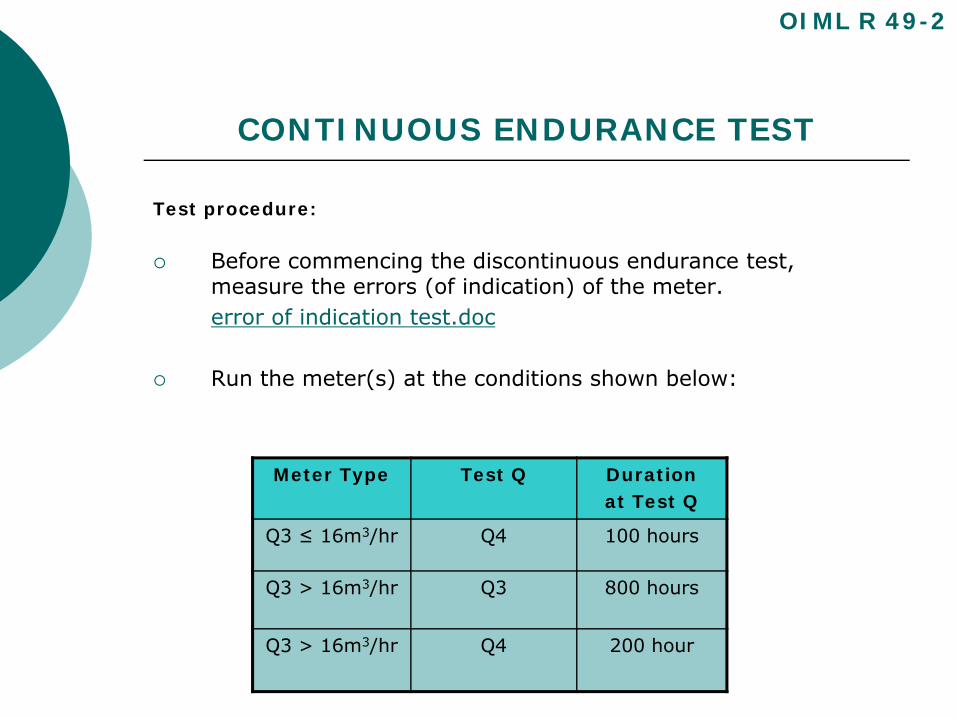
Test procedure:
Before commencing the discontinuous endurance test, measure the errors (of indication) of the meter.error of indication test.doc
Run the meter(s) at the conditions shown below:
OIML R 49-2
Meter Type Test Q Durationat Test Q
Q3 ≤ 16m3/hr Q4 100 hours
Q3 > 16m3/hr Q3 800 hours
Q3 > 16m3/hr Q4 200 hour
CONTINUOUS ENDURANCE TEST
Test procedure cont:
Following the continuous endurance test, measure the final errors (of indication).
Calculate the final relative error (of indication) for each flowrate.
For each flowrate, subtract the value of the intrinsic error (of indication) obtained before the test from the error (of indication) obtained after the test.
Complete test report R 49-3, 5.9.1.
OIML R 49-2
CONTINUOUS ENDURANCE TEST
Acceptance criteria:
After the continuous endurance test:
The variation in the error curve shall not exceed 3 % for flowrates in the lower zone (Q1 ≤ Q < Q2), or 1.5 % for flowrates in the upper zone (Q2 ≤ Q ≤ Q4). For the purpose of determining these requirements the mean values of the errors (of indication) at each flowrate shall apply.
For T30 meters, the curves shall not exceed a maximum error limit of:
± 6 % for flowrates in the lower zone (Q1 ≤ Q < Q2), and± 2.5 % for flowrates in the upper zone (Q2 ≤ Q ≤ Q4)
OIML R 49-1 3.2.2.doc
OIML R 49-2
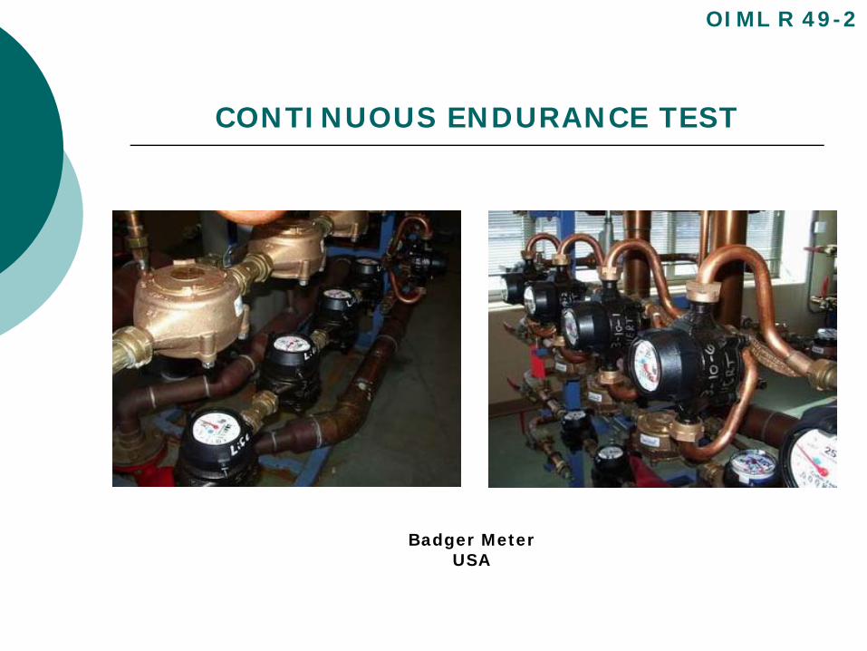
CONTINUOUS ENDURANCE TEST
OIML R 49-2
Badger MeterUSA
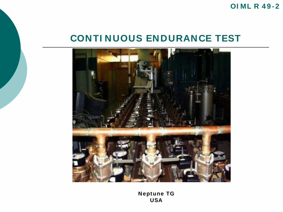
CONTINUOUS ENDURANCE TEST
OIML R 49-2
Neptune TGUSA
CONTINUOUS ENDURANCE TEST
OIML R 49-2
Neptune TGUSA
INFLUENCE QUANTITIES &
DISTURBANCES TESTS
General Requirements:
Section 7 defines the performance tests which are intended to verify that water meters perform and function as intended in a specified environment and under specified conditions.
Tests only applies to electronic meters or meters incorporating electronic devices (one exception – see below).
Static magnetic test also applies to meter with a magnetic drive
OIML R 49-2
INFLUENCE QUANTITIES & DISTURBANCES TESTS
Tests:
Tests For Influence Quantities And Disturbances.doc
Environmental classification.doc
OIML R 49-2
INFLUENCE QUANTITIES & DISTURBANCES TESTS
Dry Heat (non-condensing):
Dry heat.doc
OIML R 49-2

INFLUENCE QUANTITIES & DISTURBANCES TESTS
Dry Heat (non-condensing):
Dry heat.doc
OIML R 49-2
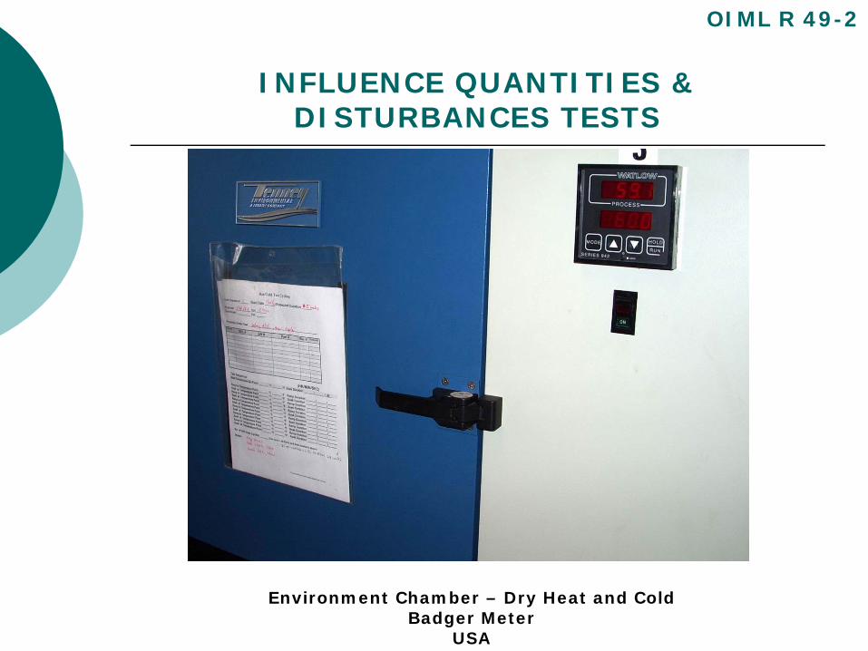
INFLUENCE QUANTITIES & DISTURBANCES TESTS
OIML R 49-2
Environment Chamber – Dry Heat and ColdBadger Meter
USA
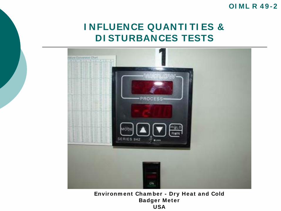
INFLUENCE QUANTITIES & DISTURBANCES TESTS
OIML R 49-2
Environment Chamber - Dry Heat and ColdBadger Meter
USA
INFLUENCE QUANTITIES & DISTURBANCES TESTS
Cold:
cold.doc
OIML R 49-2
INFLUENCE QUANTITIES & DISTURBANCES TESTS
Damp Heat, Cyclic (condensing):
damp heat.doc
OIML R 49-2
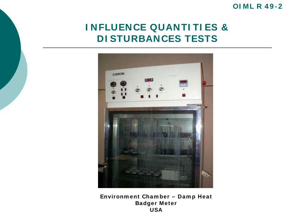
INFLUENCE QUANTITIES & DISTURBANCES TESTS
OIML R 49-2
Environment Chamber – Damp HeatBadger Meter
USA
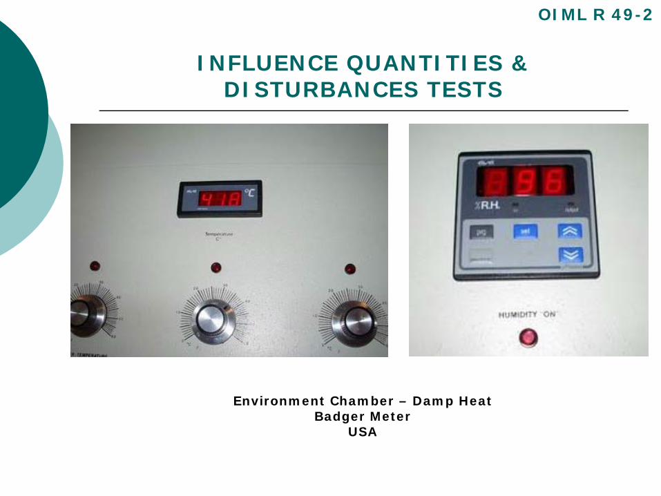
INFLUENCE QUANTITIES & DISTURBANCES TESTS
OIML R 49-2
Environment Chamber – Damp HeatBadger Meter
USA

INFLUENCE QUANTITIES & DISTURBANCES TESTS
Power Voltage Variation:
Power voltage variation.doc
OIML R 49-2
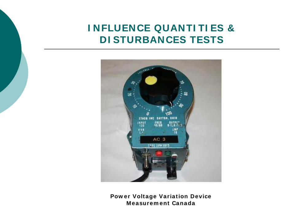
INFLUENCE QUANTITIES & DISTURBANCES TESTS
Power Voltage Variation DeviceMeasurement Canada
INFLUENCE QUANTITIES & DISTURBANCES TESTS
Short Time Power Reduction:
Short Time Power Reduction.doc
OIML R 49-2
INFLUENCE QUANTITIES & DISTURBANCES TESTS
Bursts:
Bursts.doc
OIML R 49-2
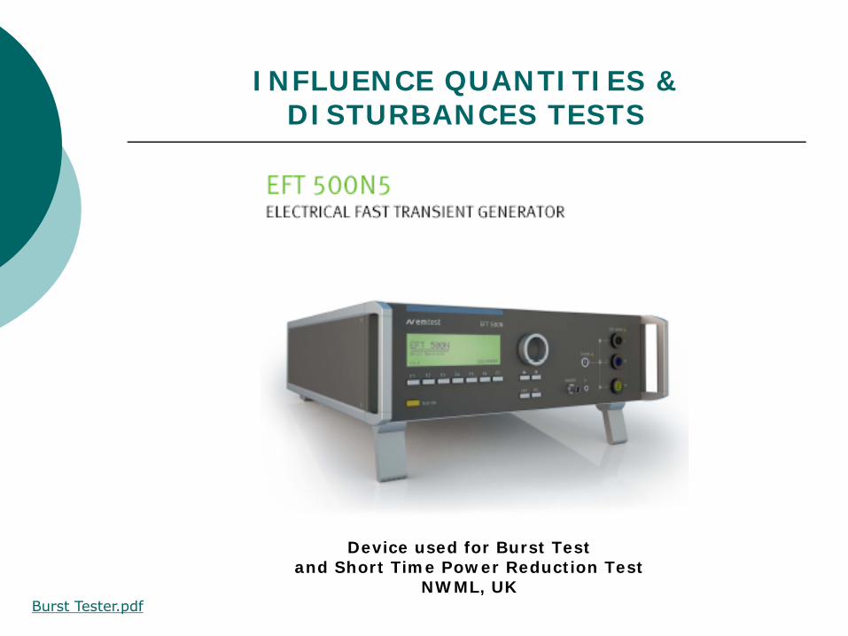
INFLUENCE QUANTITIES & DISTURBANCES TESTS
Device used for Burst Testand Short Time Power Reduction Test
NWML, UKBurst Tester.pdf
INFLUENCE QUANTITIES & DISTURBANCES TESTS
Electrostatic Discharge:
Electrostatic discharge.doc
OIML R 49-2
INFLUENCE QUANTITIES & DISTURBANCES TESTS
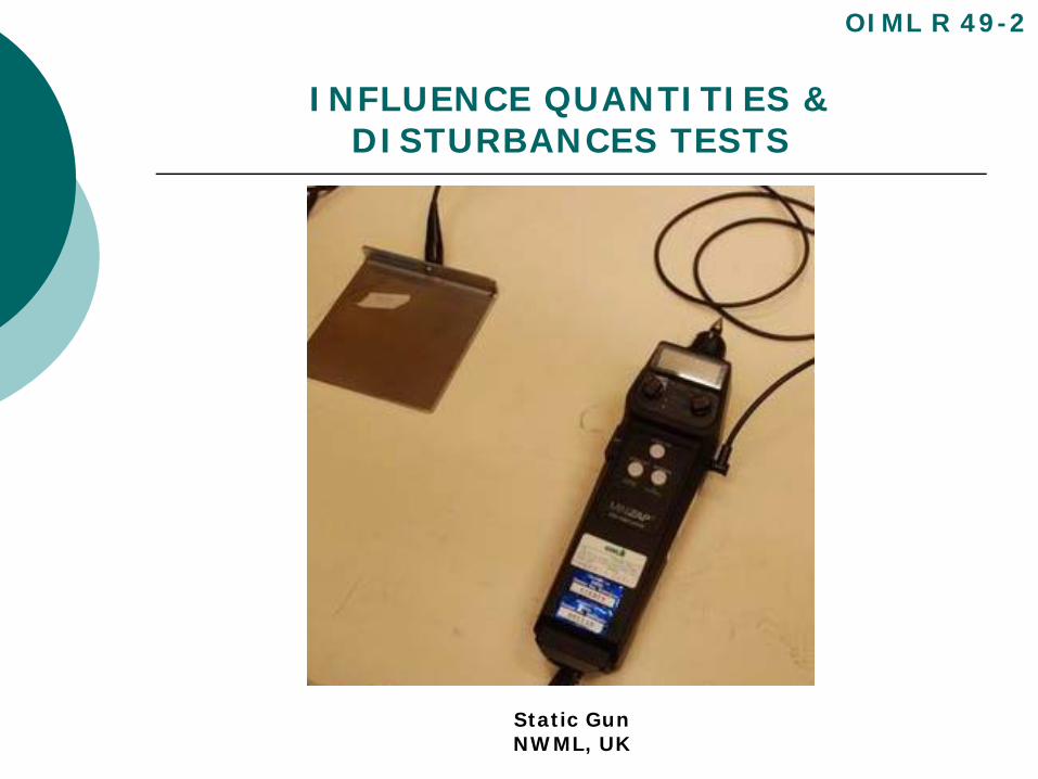
OIML R 49-2
Static GunNWML, UK

INFLUENCE QUANTITIES & DISTURBANCES TESTS
Electromagnetic Susceptibility:
Electromagnetic susceptibility.doc
OIML R 49-2
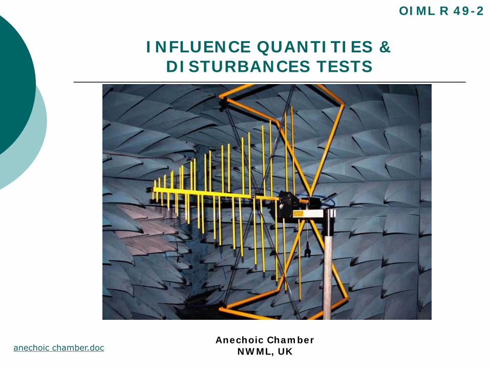
INFLUENCE QUANTITIES & DISTURBANCES TESTS
OIML R 49-2
Anechoic ChamberNWML, UKanechoic chamber.doc
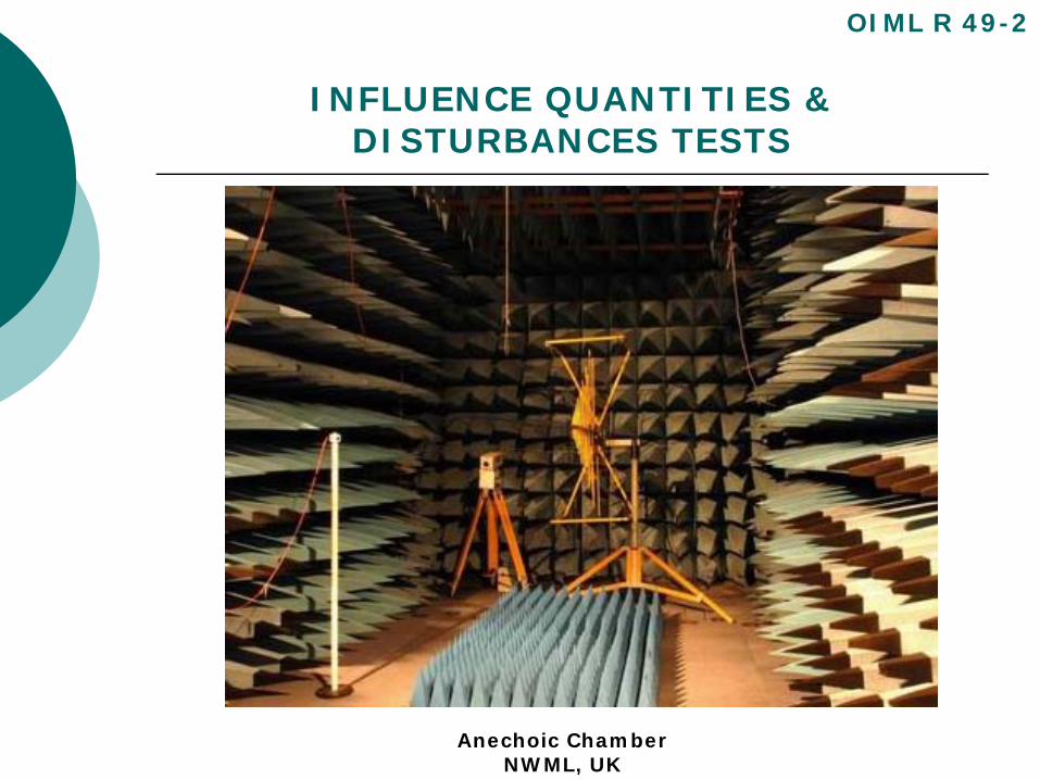
INFLUENCE QUANTITIES & DISTURBANCES TESTS
OIML R 49-2
Anechoic ChamberNWML, UK

INFLUENCE QUANTITIES & DISTURBANCES TESTS
Static Magnetic Field Test:
static magnetic field.doc
OIML R 49-2
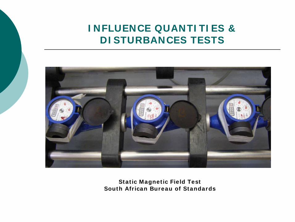
INFLUENCE QUANTITIES & DISTURBANCES TESTS
Static Magnetic Field TestSouth African Bureau of Standards
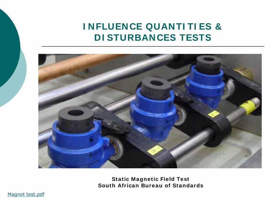
INFLUENCE QUANTITIES & DISTURBANCES TESTS
Static Magnetic Field TestSouth African Bureau of Standards
Magnet test.pdf
TEST PROGRAMFOR TYPE APPROVAL
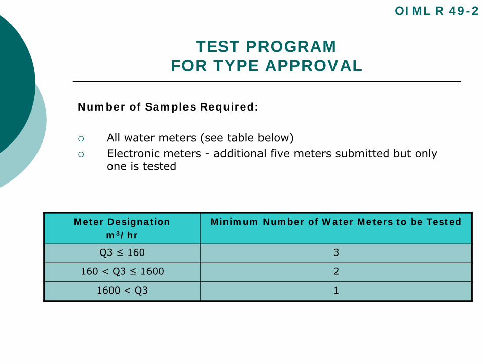
Number of Samples Required:
All water meters (see table below)Electronic meters - additional five meters submitted but only one is tested
OIML R 49-2
Meter Designationm3/hr
Minimum Number of Water Meters to be Tested
Q3 ≤ 160 3
160 < Q3 ≤ 1600 2
1600 < Q3 1
TEST PROGRAMFOR TYPE APPROVAL
Family of Water Meters:
When a family of water meters is submitted for type approval,the criteria in Annex D shall be applied by the approvingauthority in deciding if the meters conform to the definition of ‘afamily’ and in selecting which meter sizes are to be tested.
ANNEX D.doc
OIML R 49-2
OIML R 49-2Water meters intended for the metering of cold potable
water and hot water meters
TEST METHODS
Asia-PacificLegal Metrology
Forum
Questions or Comments