Embed Size (px)
Citation preview

Sensus Metering Systems
Installation andMaintenanceInstructions
Turbo-Meters Mark-II and Auto-Adjust ®
TH
E
GA
S
IN
DU
ST
RY
2
Installation and Maintenance InstructionsMark-II and Auto-Adjust ®
Sensus Metering Systems Turbo-Meters are designed for the measurement of gas. Proper application and routine maintenance will result in many years of active service life.
The following instructions are in general conformance with the recommendations contained in American Gas Association,Gas Measurement Committee Report #7, “Measurement of Gas by Turbine Meters.”
5 NominalPipe Diameters
8 Pipe Diameters(see note)
10 NominalPipe Diameters
5 NominalPipe Diameters
OptionalStraightening
Vanes
Inlet
GasTurbineMeter
TemperatureWell
BlowDown
On ReceiptCarefully examine the shipping container for any external damage prior to unpacking. Any evident damage should be reported to the carrier.
After unpacking the meter, examine it for compliance with your ordering specifications. Report any deviations to your Sensusrepresentative.
RETAIN ALL DOCUMENTS SHIPPED WITH THE METER SINCE THESE ARE REQUIRED FOR METER RECORDS.
Product SpecificationsMark-II and Auto-Adjust Turbo-Meters all use the same meter bodies, with flange dimensions conforming to ANSI B16.42 andB16.5 standards.
All Turbo-Meter bodies are hydrostatically tested at a minimum of 1.5 times the maximum rated working pressure indicated on themeter body badge. The maximum rated working pressure stampedon the meter body badge must not be exceeded in service.
Standard construction aluminum, ductile iron and steel bodied Turbo-Meters will operate over a flowing gas temperature range of -20°F to + 165°F (-28.9°C to + 74°C). Special construction isavailable for lower and higher operating temperatures.
InstallationTurbo-Meters are basically velocity sensing devices which derive volume by sensing the flow rate through the known cross-sectional area of the measuring module. Accurate velocity sensingis essential in deriving accurate volume measurement.
Accessory devices in close proximity to the Turbo-Meter set can cause a jetting or swing condition, upsetting the normal velocityprofile of the gas stream. Extensive tests of Turbo-Meters at various flow rates and pressures have defined the recommendedpiping installations which should result in optimal volume measurement accuracy.
The most common installations are as follows:
1. Inline A minimum run of ten (10) pipe diameters (DN) of straight pipe must be used between any flow-altering device (other than flow throttling) and the inlet flange of the Turbo-Meter (Figure 1).
Note: A total of eighteen (18) pipe diameters must be usedbetween any throttling device (regulator, control valve, etc.)installed upstream of the meter and the meter inlet flange. This inlet pipe should be nominally the same interior diameter asthe meter body. Minor variations in the piping ID due to use of piping with different wall thickness will not affect the meter accuracy. Inline straightening vanes locate five pipe diametersupstream of the meter inlet are optional. Extensive testing in lineswith and without straightening vanes mounted in the inlet piping demonstrates no difference in accuracies when usingTurbo-Meters with built in straightening vanes.
Spool Assembly4 Nominal PipeDiameters (DN)
90°Elbowor Tee
MaximumReduction
One NominalPipe Size
Gas TurbineMeter
TemperatureWell
StandardorReducingElbowor Tee
Space for Valving
2 NominalPipe Diameters
Space for Valving,Filter or Strainer
90° Standard orLong Radius Elbow
Minimum
Inlet
StraighteningValves
Note: A throttling device (regulator control valve, etc.) upstream of the meter run requires a minimum of eight (8) pipe diameters(DN) between such device and the meter run.
2. Off-Set, Short Coupled Turbo-Meters may be installed in short-coupled sets as illustrated in Figure 2. Note that the flow-restricting devices must be installed in the vertical riser and that a 90° fitting must be used at the inlet to the meter run. This fitting may be an elbow or a tee. A straight run of pipe, equal in ID to the meter size and four diameters long, as well as equipped with straightening vanes at the inlet end, is attached to the inlet side of the meter.
Figure 1Recommended Installation of an In-Line Gas Turbine Meter
(Minimum Lengths)
Figure 2Short Coupled Installation of an In-Line Gas Turbine Meter
(Minimum Lengths)
3
Installation and Maintenance InstructionsMark-II and Auto-Adjust ®
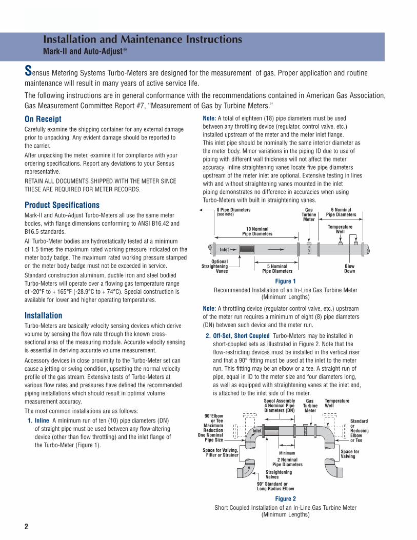
3. Offset, Close Coupled Sensus Turbo-Meters manufactured since October, 1974 incorporate integral straightening vanes. This design eliminates the need for long inlet runs and enablesTurbo-Meters to be close-coupled as illustrated in Figure 3.
90°Elbowor Tee
MaximumReduction
One NominalPipe Size
Gas TurbineMeter
TemperatureWell
StandardorReducingElbow
Space for Valving
Space for Valving,Filter or Strainer
90°
Inlet
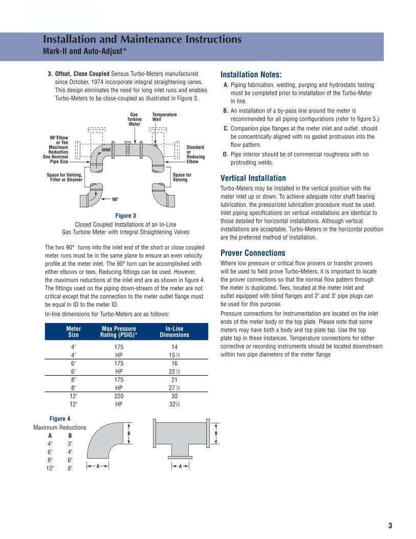
The two 90° turns into the inlet end of the short or close coupledmeter runs must be in the same plane to ensure an even velocityprofile at the meter inlet. The 90° turn can be accomplished witheither elbows or tees. Reducing fittings can be used. However, the maximum reductions at the inlet end are as shown in figure 4.The fittings used on the piping down-stream of the meter are notcritical except that the connection to the meter outlet flange mustbe equal in ID to the meter ID.
In-line dimensions for Turbo-Meters are as follows:
Meter Max Pressure In-LineSize Rating (PSIG)* Dimensions
4" 175 144" HP 15 1⁄26" 175 166" HP 22 1⁄28" 175 218" HP 27 1⁄412" 220 3012" HP 321⁄2
A A
B B
Installation Notes:A. Piping fabrication, welding, purging and hydrostatic testing
must be completed prior to installation of the Turbo-Meter in line.
B. An installation of a by-pass line around the meter is recommended for all piping configurations (refer to figure 5.)
C. Companion pipe flanges at the meter inlet and outlet should be concentrically aligned with no gasket protrusion into the flow pattern.
D. Pipe interior should be of commercial roughness with no protruding welds.
Vertical InstallationTurbo-Meters may be installed in the vertical position with the meter inlet up or down. To achieve adequate rotor shaft bearinglubrication, the pressurized lubrication procedure must be used.Inlet piping specifications on vertical installations are identical tothose detailed for horizontal installations. Although vertical installations are acceptable, Turbo-Meters in the horizontal positionare the preferred method of installation.
Prover Connections Where low pressure or critical flow provers or transfer provers will be used to field prove Turbo-Meters, it is important to locatethe prover connections so that the normal flow pattern through the meter is duplicated. Tees, located at the meter inlet and outlet equipped with blind flanges and 2" and 3" pipe plugs can be used for this purpose.
Pressure connections for instrumentation are located on the inlet ends of the meter body or the top plate. Please note that somemeters may have both a body and top plate tap. Use the top plate tap in these instances. Temperature connections for eithercorrective or recording instruments should be located downstreamwithin two pipe diameters of the meter flange
Figure 3Closed Coupled Installations of an In-Line
Gas Turbine Meter with Integral Straightening Valves
Figure 4Maximum Reductions
A B4" 3"6" 4"8" 6"12" 8"
4
Installation and Maintenance InstructionsMark-II and Auto-Adjust ®
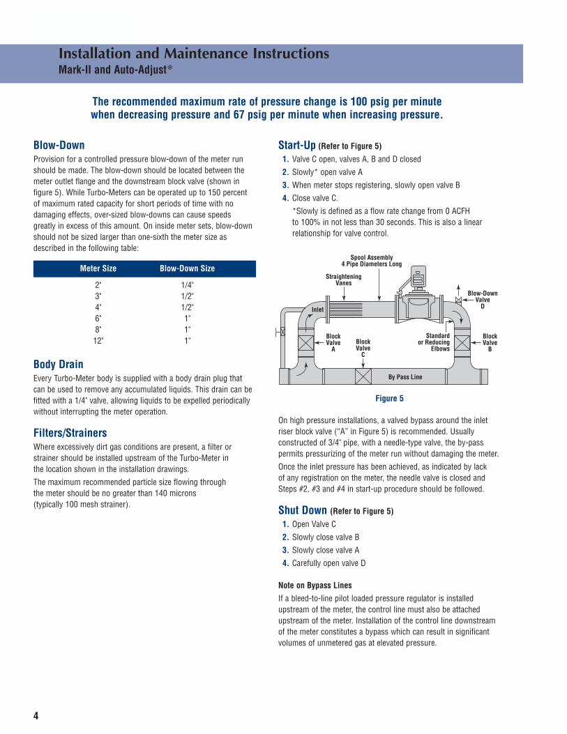
Blow-DownProvision for a controlled pressure blow-down of the meter run should be made. The blow-down should be located between themeter outlet flange and the downstream block valve (shown in figure 5). While Turbo-Meters can be operated up to 150 percentof maximum rated capacity for short periods of time with no damaging effects, over-sized blow-downs can cause speeds greatly in excess of this amount. On inside meter sets, blow-downshould not be sized larger than one-sixth the meter size asdescribed in the following table:
The recommended maximum rate of pressure change is 100 psig per minute when decreasing pressure and 67 psig per minute when increasing pressure.
Meter Size Blow-Down Size
2" 1/4"3" 1/2"4" 1/2"6" 1"8" 1"12" 1"
Body Drain Every Turbo-Meter body is supplied with a body drain plug that can be used to remove any accumulated liquids. This drain can befitted with a 1/4" valve, allowing liquids to be expelled periodicallywithout interrupting the meter operation.
Filters/Strainers Where excessively dirt gas conditions are present, a filter or strainer should be installed upstream of the Turbo-Meter in the location shown in the installation drawings.
The maximum recommended particle size flowing through the meter should be no greater than 140 microns (typically 100 mesh strainer).
Start-Up (Refer to Figure 5)
1. Valve C open, valves A, B and D closed
2. Slowly* open valve A
3. When meter stops registering, slowly open valve B
4. Close valve C.
*Slowly is defined as a flow rate change from 0 ACFH to 100% in not less than 30 seconds. This is also a linear relationship for valve control.
Spool Assembly4 Pipe Diameters Long
Inlet
StraighteningVanes
Blow-DownValve
D
BlockValve
B
Standardor Reducing
Elbows
BlockValve
ABlockValve
C
By Pass Line
On high pressure installations, a valved bypass around the inletriser block valve (“A” in Figure 5) is recommended. Usually constructed of 3/4" pipe, with a needle-type valve, the by-pass permits pressurizing of the meter run without damaging the meter.
Once the inlet pressure has been achieved, as indicated by lack of any registration on the meter, the needle valve is closed andSteps #2, #3 and #4 in start-up procedure should be followed.
Shut Down (Refer to Figure 5)
1. Open Valve C
2. Slowly close valve B
3. Slowly close valve A
4. Carefully open valve D
Note on Bypass Lines
If a bleed-to-line pilot loaded pressure regulator is installed upstream of the meter, the control line must also be attachedupstream of the meter. Installation of the control line downstreamof the meter constitutes a bypass which can result in significant volumes of unmetered gas at elevated pressure.
Figure 5
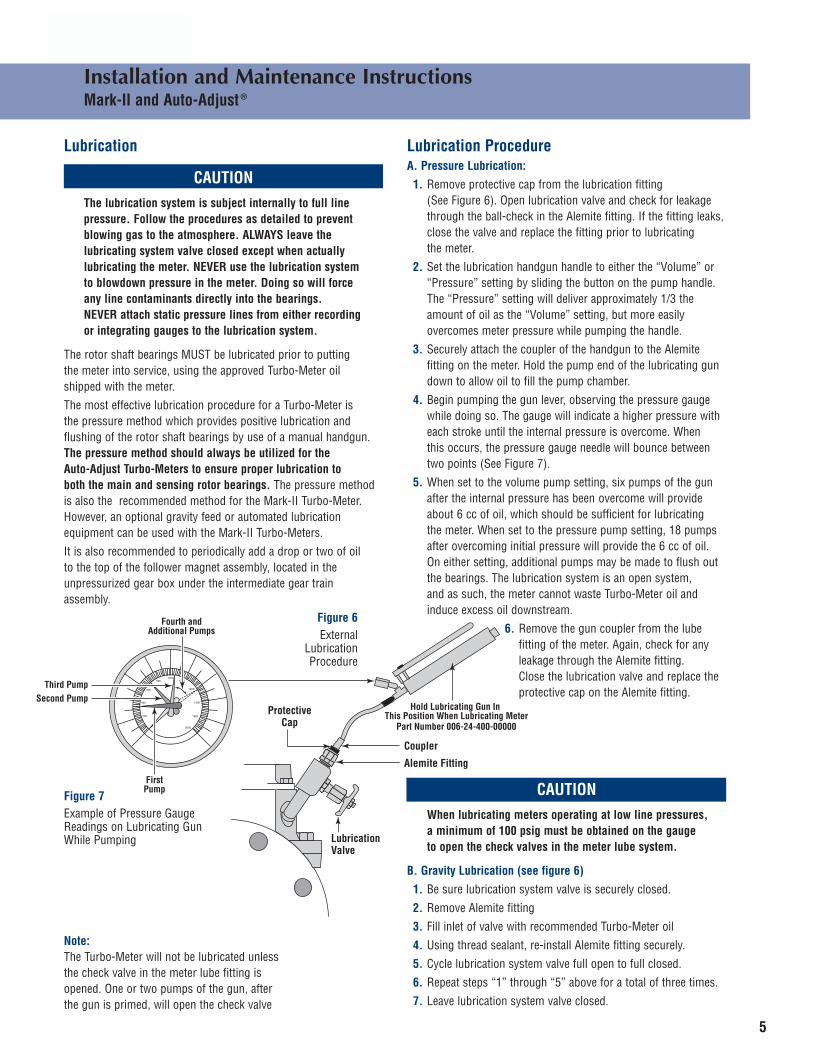
FirstPump
Second PumpThird Pump
Fourth andAdditional Pumps
Hold Lubricating Gun In This Position When Lubricating Meter
Part Number 006-24-400-00000
Protective Cap
Lubrication Valve
Coupler
Alemite Fitting
5
Installation and Maintenance InstructionsMark-II and Auto-Adjust ®
Lubrication
CAUTIONThe lubrication system is subject internally to full line pressure. Follow the procedures as detailed to prevent blowing gas to the atmosphere. ALWAYS leave the lubricating system valve closed except when actually lubricating the meter. NEVER use the lubrication system to blowdown pressure in the meter. Doing so will force any line contaminants directly into the bearings. NEVER attach static pressure lines from either recording or integrating gauges to the lubrication system.
The rotor shaft bearings MUST be lubricated prior to putting the meter into service, using the approved Turbo-Meter oil shipped with the meter.
The most effective lubrication procedure for a Turbo-Meter is the pressure method which provides positive lubrication and flushing of the rotor shaft bearings by use of a manual handgun.The pressure method should always be utilized for the Auto-Adjust Turbo-Meters to ensure proper lubrication to both the main and sensing rotor bearings. The pressure method is also the recommended method for the Mark-II Turbo-Meter.However, an optional gravity feed or automated lubrication equipment can be used with the Mark-II Turbo-Meters.
It is also recommended to periodically add a drop or two of oil to the top of the follower magnet assembly, located in the unpressurized gear box under the intermediate gear train assembly.
Lubrication ProcedureA. Pressure Lubrication:
1. Remove protective cap from the lubrication fitting (See Figure 6). Open lubrication valve and check for leakage through the ball-check in the Alemite fitting. If the fitting leaks,close the valve and replace the fitting prior to lubricating the meter.
2. Set the lubrication handgun handle to either the “Volume” or “Pressure” setting by sliding the button on the pump handle. The “Pressure” setting will deliver approximately 1/3 the amount of oil as the “Volume” setting, but more easily overcomes meter pressure while pumping the handle.
3. Securely attach the coupler of the handgun to the Alemite fitting on the meter. Hold the pump end of the lubricating gun down to allow oil to fill the pump chamber.
4. Begin pumping the gun lever, observing the pressure gauge while doing so. The gauge will indicate a higher pressure with each stroke until the internal pressure is overcome. When this occurs, the pressure gauge needle will bounce between two points (See Figure 7).
5. When set to the volume pump setting, six pumps of the gun after the internal pressure has been overcome will provide about 6 cc of oil, which should be sufficient for lubricating the meter. When set to the pressure pump setting, 18 pumps after overcoming initial pressure will provide the 6 cc of oil. On either setting, additional pumps may be made to flush out the bearings. The lubrication system is an open system, and as such, the meter cannot waste Turbo-Meter oil and induce excess oil downstream.
6. Remove the gun coupler from the lube fitting of the meter. Again, check for any leakage through the Alemite fitting. Close the lubrication valve and replace the protective cap on the Alemite fitting.
CAUTIONWhen lubricating meters operating at low line pressures, a minimum of 100 psig must be obtained on the gauge to open the check valves in the meter lube system.
B. Gravity Lubrication (see figure 6)
1. Be sure lubrication system valve is securely closed.
2. Remove Alemite fitting
3. Fill inlet of valve with recommended Turbo-Meter oil
4. Using thread sealant, re-install Alemite fitting securely.
5. Cycle lubrication system valve full open to full closed.
6. Repeat steps “1” through “5” above for a total of three times.
7. Leave lubrication system valve closed.
Note:The Turbo-Meter will not be lubricated unless the check valve in the meter lube fitting isopened. One or two pumps of the gun, after the gun is primed, will open the check valve
Figure 7Example of Pressure GaugeReadings on Lubricating GunWhile Pumping
Figure 6External
Lubrication Procedure
6
Installation and Maintenance InstructionsMark-II and Auto-Adjust ®
Recommended Lubrication OilsSensus Turbo-Meter oil specifications conform to Military Specifications MIL-L-6085A. Generally, this specification refers to a synthetic, diester-based lubricating oil with an SAE viscositynumber of 5W containing NO PCBs. Recommended Turbo-Meterlubrication oils and the sources of supply are as follows:
Oil Source Source
Ultra-Chem CorporationChemlube #201 900 Centerpoint Blvd.
New Castle, Delaware 19720Telephone: 302-325-9880
Call AnderolAnderol 401D 973-887-7410 Ext. 115
For LocalAnderol Distributor
Recommended lubrication oil is available from Sensus in smallplastic bottles and one gallon cans as follows:
4 oz. bottle – Sensus Part Number 006-22-405-01000One gallon can – Sensus Part Number 006-22-405-02000
HandgunsTwo lubricating handguns are available including apressure gauge and, importantly, a relief valve, as follows:
High pressure application (0-2000 psig) Sensus Part Number 006-24-400-00000
Low pressure application (0-600 psig) Sensus Part Number 006-24-400-01000
Frequency of LubricationThe frequency of lubrication required in order to maintain the rotor shaft bearings in good operating condition is a function ofthe severity of the service. High pressure, high flow rates, andhigh temperatures, coupled with dirty gas conditions require morefrequent lubrication. Lubricate the bearings following the detailedprocedure at the time the initial installation is made with the oilshipped with the meter. Subsequent lubrication should be donemonthly with the period extended as operating conditions permit.Lubrication of the meter prior to installation will result in theinconvenience of oil flowing out of the open system.
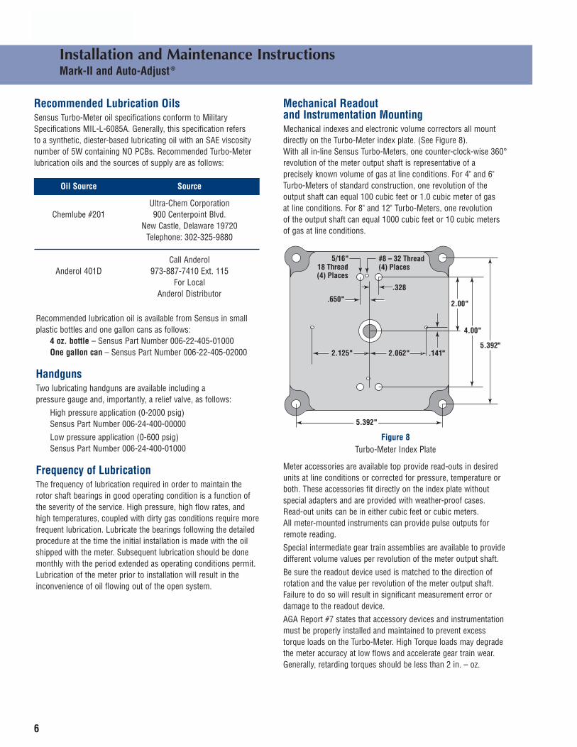
Mechanical Readout and Instrumentation MountingMechanical indexes and electronic volume correctors all mount directly on the Turbo-Meter index plate. (See Figure 8). With all in-line Sensus Turbo-Meters, one counter-clock-wise 360°revolution of the meter output shaft is representative of a precisely known volume of gas at line conditions. For 4" and 6"Turbo-Meters of standard construction, one revolution of the output shaft can equal 100 cubic feet or 1.0 cubic meter of gas at line conditions. For 8" and 12" Turbo-Meters, one revolution of the output shaft can equal 1000 cubic feet or 10 cubic meters of gas at line conditions.
2.125" 2.062"
.650"
#8 – 32 Thread (4) Places
5/16"18 Thread(4) Places
.328
2.00"
4.00"
5.392".141"
5.392"
Meter accessories are available top provide read-outs in desiredunits at line conditions or corrected for pressure, temperature orboth. These accessories fit directly on the index plate without special adapters and are provided with weather-proof cases. Read-out units can be in either cubic feet or cubic meters. All meter-mounted instruments can provide pulse outputs forremote reading.
Special intermediate gear train assemblies are available to provide different volume values per revolution of the meter output shaft.
Be sure the readout device used is matched to the direction of rotation and the value per revolution of the meter output shaft.Failure to do so will result in significant measurement error ordamage to the readout device.
AGA Report #7 states that accessory devices and instrumentation must be properly installed and maintained to prevent excesstorque loads on the Turbo-Meter. High Torque loads may degradethe meter accuracy at low flows and accelerate gear train wear.Generally, retarding torques should be less than 2 in. – oz.
Figure 8Turbo-Meter Index Plate
7
Installation and Maintenance InstructionsMark-II and Auto-Adjust ®
Periodic Inspection
CAUTIONAll pressure in the meter run must be relieved to a non-hazardous location prior to the disassembly of the meter
The meter mechanism should be inspected periodically to ensure that all components are in good operating condition. The frequencyof inspection is a function of the severity of the application. Ameter operating at or near its maximum rated capacity at highpressure on a “dirty” gas application will require more frequentinspection than a meter on a less severe application. The recom-mended periodic inspection procedure is as follows:
1. Follow previously defined steps for “SHUT-DOWN”
2. Remove the readout device from the meter. The high frequency device must also be removed on end-entry type meters.
3. After all pressure inside the meter has been relieved, remove bolts attaching meter top plate to the body (see Parts List Illustration). For end entry type meters, remove the screws retaining the nosecone. Meters with center set screws may be replaced with an eye bolt or similar item for extraction.
4. Carefully lift the complete internal mechanism assembly vertically out of the meter body. Note: Two opposing bolt holesin the top plate are tapped to accept eye bolts to aid in lifting the module out. For end entry type meters, remove the measuring module through the inlet side.
5. Hang the internal mechanism assembly from the meter body so that two bolt holes in the top plate line up with two holes inthe body. Insert two bolts to firmly attach mechanism to body.
6. Visually inspect the interior of the body. Remove any liquid or debris which may be present. Use an angled inspection mirror and flashlight to look for bent, missing or otherwise damaged straightening vanes attached to the nosecone. A damaged nosecone may be replaced without recalibration of the module.
7. Visually inspect the rotor and flow passages of the internal housing assembly. A damaged rotor should be replaced, and the meter recalibrated.
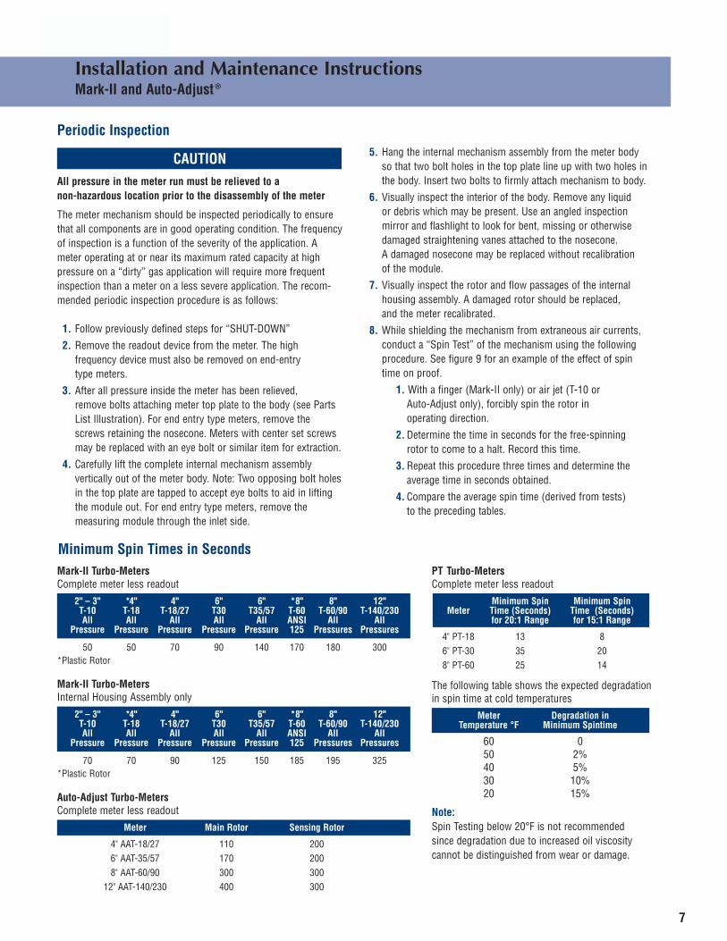
8. While shielding the mechanism from extraneous air currents, conduct a “Spin Test” of the mechanism using the following procedure. See figure 9 for an example of the effect of spin time on proof.
1. With a finger (Mark-II only) or air jet (T-10 or Auto-Adjust only), forcibly spin the rotor in operating direction.
2. Determine the time in seconds for the free-spinning rotor to come to a halt. Record this time.
3. Repeat this procedure three times and determine the average time in seconds obtained.
4. Compare the average spin time (derived from tests) to the preceding tables.
Minimum Spin Times in SecondsMark-II Turbo-MetersComplete meter less readout
2" – 3" *4" 4" 6" 6" *8" 8" 12"T-10 T-18 T-18/27 T30 T35/57 T-60 T-60/90 T-140/230All All All All All ANSI All All
Pressure Pressure Pressure Pressure Pressure 125 Pressures Pressures
50 50 70 90 140 170 180 300*Plastic Rotor
Mark-II Turbo-MetersInternal Housing Assembly only
2" – 3" *4" 4" 6" 6" *8" 8" 12"T-10 T-18 T-18/27 T30 T35/57 T-60 T-60/90 T-140/230All All All All All ANSI All All
Pressure Pressure Pressure Pressure Pressure 125 Pressures Pressures
70 70 90 125 150 185 195 325*Plastic Rotor
Auto-Adjust Turbo-MetersComplete meter less readout
Meter Main Rotor Sensing Rotor
4" AAT-18/27 110 2006" AAT-35/57 170 2008" AAT-60/90 300 300
12" AAT-140/230 400 300
PT Turbo-Meters Complete meter less readout
Minimum Spin Minimum SpinMeter Time (Seconds) Time (Seconds)
for 20:1 Range for 15:1 Range
4" PT-18 13 86" PT-30 35 208" PT-60 25 14
The following table shows the expected degradation in spin time at cold temperatures
Meter Degradation inTemperature °F Minimum Spintime
60 050 2%40 5%30 10%20 15%
Note:Spin Testing below 20°F is not recommendedsince degradation due to increased oil viscositycannot be distinguished from wear or damage.

8
Installation and Maintenance InstructionsMark-II and Auto-Adjust ®
x
xx
xx
xx
0 2 4 6 8 10 12 14 16 18 20 22 24 26 28 30 32
–5
–3
–1
0
+1
+3
Flow Rate, SCFH X 103, 0.60 SP. GR. GAS
x
130 SEC120 SEC95 SEC80 SEC67 SECx
Perc
ent E
rror
, %
NOTEWhen spin-testing an Auto-Adjust Turbo-Meter, Sensus recommends that an air jet be used on the inlet side to spin bothrotors simultaneously. The air jet should remain on until the sensing rotor is spinning in the same direction as the main rotor.
9. Failure to achieve the specified spin time most probably indicates a need to lubricate the rotor shaft bearings following the previously defined procedure. After lubricating the bearings, forcibly spin the rotor several minutes to throw off excess oil prior to repeating the spin test.
Spin times above the minimums listed are typical, and indicate a meter with acceptable friction levels and accuracy.
10. Inspect top plate to body “o” ring and replace if necessary.
Inspect the module/oil seal and replace if necessary.
11. Remove bolts attaching top plate to body (see 5). End entry meters equipped with an aligning pin should be positioned with the inside groove of the inlet.
12. Carefully insert measuring module into body being sure rotor is positioned toward the inlet end. DO NOT FORCE.
13. Re-insert top plate body bolts and tighten securely. Replace the nosecone retaining screw on end entry meters and re-apply loctite on set screw equipped modules.
14. Mount readout device on index plate being careful to properly align the driving mechanism from the meter to the driving mechanism on the index or instrument.
15. Re-pressure the meter following the Start-Up procedure previously identified (page 3).
16. Check top plate to body joint for leaks.
17. Following start-up, check the readout device for proper registration.
18. Before leaving the meter site, it is best to lubricate the meter once it is pressurized and gas is flowing through it.
Figure 9T-35 Mark-II Turbo-Meter Effect of Spin Time on Proof
9
Installation and Maintenance InstructionsMark-II and Auto-Adjust ®
47-47T74-73T
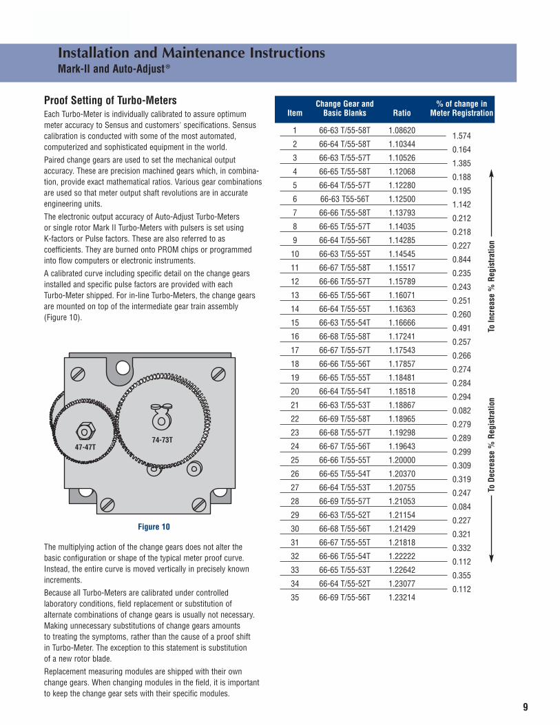
Proof Setting of Turbo-MetersEach Turbo-Meter is individually calibrated to assure optimum meter accuracy to Sensus and customers' specifications. Sensuscalibration is conducted with some of the most automated, computerized and sophisticated equipment in the world.
Paired change gears are used to set the mechanical output accuracy. These are precision machined gears which, in combina-tion, provide exact mathematical ratios. Various gear combinationsare used so that meter output shaft revolutions are in accurateengineering units.
The electronic output accuracy of Auto-Adjust Turbo-Meters or single rotor Mark II Turbo-Meters with pulsers is set using K-factors or Pulse factors. These are also referred to as coefficients. They are burned onto PROM chips or programmedinto flow computers or electronic instruments.
A calibrated curve including specific detail on the change gears installed and specific pulse factors are provided with each Turbo-Meter shipped. For in-line Turbo-Meters, the change gearsare mounted on top of the intermediate gear train assembly (Figure 10).
The multiplying action of the change gears does not alter the basic configuration or shape of the typical meter proof curve.Instead, the entire curve is moved vertically in precisely knownincrements.
Because all Turbo-Meters are calibrated under controlled laboratory conditions, field replacement or substitution of alternate combinations of change gears is usually not necessary.Making unnecessary substitutions of change gears amounts to treating the symptoms, rather than the cause of a proof shift in Turbo-Meter. The exception to this statement is substitution of a new rotor blade.
Replacement measuring modules are shipped with their own change gears. When changing modules in the field, it is importantto keep the change gear sets with their specific modules.
Figure 10
Change Gear and % of change in Item Basic Blanks Ratio Meter Registration
1 66-63 T/55-58T 1.086201.574
2 66-64 T/55-58T 1.103440.164
3 66-63 T/55-57T 1.105261.385
4 66-65 T/55-58T 1.120680.188
5 66-64 T/55-57T 1.122800.195
6 66-63 T55-56T 1.125001.142
7 66-66 T/55-58T 1.137930.212
8 66-65 T/55-57T 1.140350.218
9 66-64 T/55-56T 1.142850.227
10 66-63 T/55-55T 1.145450.844
11 66-67 T/55-58T 1.155170.235
12 66-66 T/55-57T 1.157890.243
13 66-65 T/55-56T 1.160710.251
14 66-64 T/55-55T 1.163630.260
15 66-63 T/55-54T 1.166660.491
16 66-68 T/55-58T 1.172410.257
17 66-67 T/55-57T 1.175430.266
18 66-66 T/55-56T 1.178570.274
19 66-65 T/55-55T 1.184810.284
20 66-64 T/55-54T 1.185180.294
21 66-63 T/55-53T 1.188670.082
22 66-69 T/55-58T 1.189650.279
23 66-68 T/55-57T 1.192980.289
24 66-67 T/55-56T 1.196430.299
25 66-66 T/55-55T 1.200000.309
26 66-65 T/55-54T 1.203700.319
27 66-64 T/55-53T 1.207550.247
28 66-69 T/55-57T 1.210530.084
29 66-63 T/55-52T 1.211540.227
30 66-68 T/55-56T 1.214290.321
31 66-67 T/55-55T 1.218180.332
32 66-66 T/55-54T 1.222220.112
33 66-65 T/55-53T 1.226420.355
34 66-64 T/55-52T 1.230770.112
35 66-69 T/55-56T 1.23214
To In
crea
se %
Regi
stra
tion
To D
ecre
ase
%Re
gist
ratio
n

10
Installation and Maintenance InstructionsMark-II and Auto-Adjust ®
Change Gear and % of change in Item Basic Blanks Ratio Meter Registration
35 66-69 T/55-56T 1.232140.343
36 66-68 T/55-55T 1.236360.354
37 66-67 T/55-54T 1.240740.366
38 66-66 T/55-53T 1.245280.379
39 66-65 T/55-52T 1.250000.364
40 66-69 T/55-55T 1.254550.376
41 66-68 T/55-54T 1.259260.388
42 66-67 T/55-53T 1.264150.402
43 66-66 T/55-52T 1.269230.673
44 66-69 T/55-54T 1.277780.410
45 66-68 T/55-53T 1.283020.424
46 66-67 T/55-52T 1.288460.608
47 69-70 T/52-54T 1.296300.431
48 66-69 T/55-53 1.301890.446
49 71-68 T/50-52T 1.307690.000
50 66-68 T/55-52T 1.307690.461
51 69-67 T/52-51T 1.313730.535
52 69-70 T/52-53T 1.320750.467
53 66-69 T/55-52T 1.326920.000
54 71-69 T/50-52T 1.326920.483
55 71-68 T/50-51T 1.333330.500
56 69-67 T/52-50T 1.340000.459
57 71-70 T/50-52T 1.346150.504
58 71-69 T/50-51T 1.352940.522
59 71-68 T/50-50T 1.360000.396
60 71-71 T/50-52T 1.365380.525
61 71-70 T/50-51T 1.372550.543
62 71-69 T/50-50T 1.380000.334
63 71-72 T/50-52T 1.384620.227
64 71-68 T/50-49T 1.387760.317
65 71-71 T/50-51T 1.392160.563
66 71-70 T/50-50T 1.400000.275
67 71-73 T/50-52T 1.403850.308
68 71-69 T/50-49T 1.408160.256
69 71-72 T/50-51T 1.411760.347
70 71-68 T/50-48T 1.416670.235
a 71 71-71 T/50-50T 1.420000.217
72 71-74 T/50-52T 1.423080.386
73 71-70 T/50-49T 1.428570.196
74 71-73 T/50-51T 1.43137
Change Gear and % of change in Item Basic Blanks Ratio Meter Registration
74 71-73 T/50-51T 1.431370.428
75 71-69 T/50-48T 1.437500.174
76 71-72 T/50-50T 1.440000.624
77 71-71 T/50-49T 1.448980.138
78 71-74 T/50-51T 1.450980.507
79 71-70 T/50-48T 1.458330.114
80 71-73 T/50-50T 1.460000.643
81 71-72 T/50-49T 1.469390.666
82 71-71 T/50-48T 1.479170.056
83 71-74 T/50-50T 1.480000.662
84 71-73 T/50-49T 1.489800.685
85 71-72 T/50-48T 1.500000.680
86 71-74 T/50-49T 1.510200.000
87 74-74 T/47-49T 1.510200.704
88 71-73 T/50-48T 1.520830.000
89 74-73 T/47-48T 1.520830.643
90 74-75 T/47-49T 1.530610.085
91 74-72 T/47-47T 1.531910.637
92 71-74 T/50-48T 1.541670.000
93 74-74 T/47-48T 1.541670.118
94 74-71 T/47-46T 1.543480.489
95 74-76 T/47-49T 1.551020.140
96 74-73 T/47-47T 1.553190.599
97 74-75 T/47-48T 1.562500.571
98 74-77 T/47-49T 1.571430.193
99 74-74 T/47-47T 1.574470.563
100 74-76 T/47-48T 1.583330.229
101 74-73 T/47-46T 1.586960.554
102 74-75 T/47-47T 1.595740.528
103 74-77 T/47-48T 1.604170.282
104 74-74 T/47-46T 1.608700.518
105 74-76 T/47-47T 1.617020.322
106 74-73 T/47-45T 1.622220.506
107 74-75 T/47-46T 1.630430.482
108 74-77 T/47-47T 1.638300.375
109 74-74 T/47-45T 1.644440.470
110 74-76 T/47-46T 1.652170.419
111 74-73 T/47-44T 1.659090.457
112 74-75 T/47-45T 1.666670.435
113 74-77 T/47-46T 1.67391
To In
crea
se %
Regi
stra
tion
To D
ecre
ase
%Re
gist
ratio
n
To In
crea
se %
Regi
stra
tion
To D
ecre
ase
%Re
gist
ratio
n
11
Installation and Maintenance InstructionsMark-II and Auto-Adjust ®
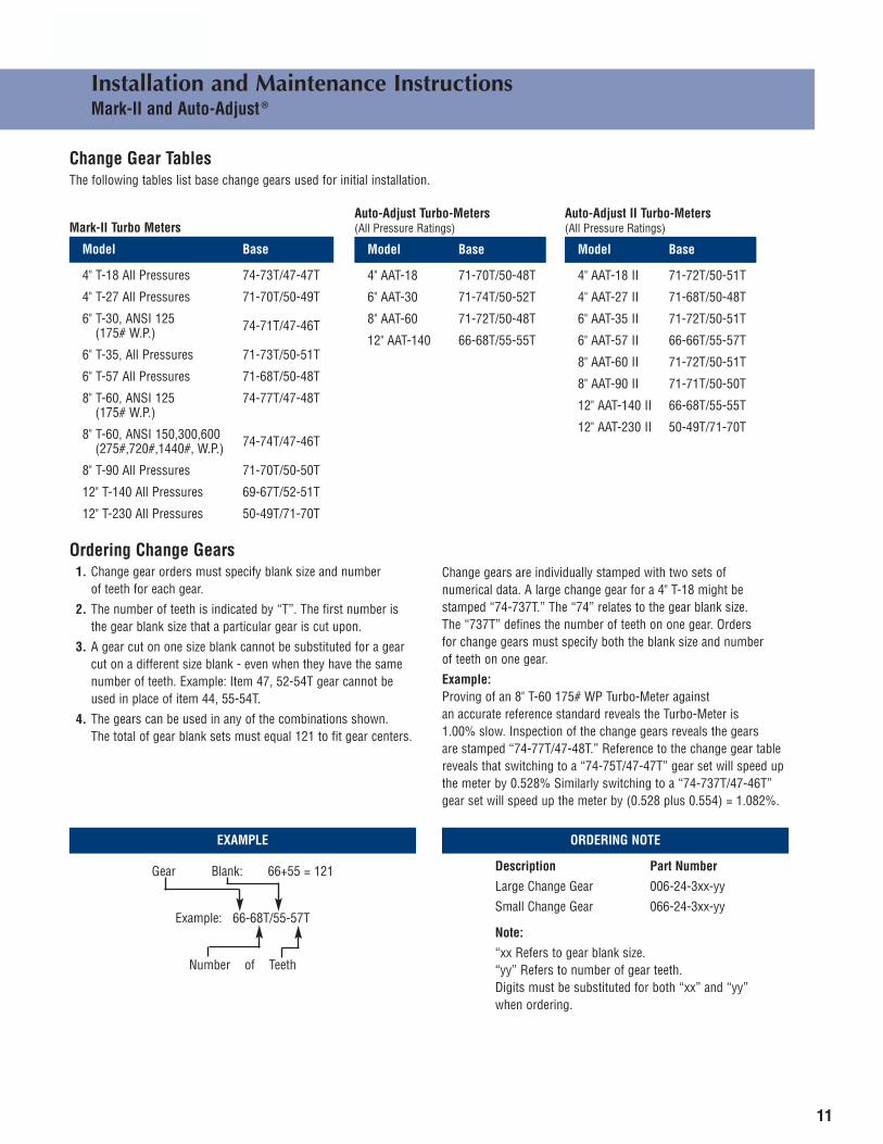
Change Gear TablesThe following tables list base change gears used for initial installation.
Mark-II Turbo Meters
Model Base
4" T-18 All Pressures 74-73T/47-47T
4" T-27 All Pressures 71-70T/50-49T
6" T-30, ANSI 125 74-71T/47-46T(175# W.P.)
6" T-35, All Pressures 71-73T/50-51T
6" T-57 All Pressures 71-68T/50-48T
8" T-60, ANSI 125 74-77T/47-48T(175# W.P.)
8" T-60, ANSI 150,300,600 74-74T/47-46T(275#,720#,1440#, W.P.)
8" T-90 All Pressures 71-70T/50-50T
12" T-140 All Pressures 69-67T/52-51T
12" T-230 All Pressures 50-49T/71-70T
Auto-Adjust Turbo-Meters (All Pressure Ratings)
Model Base
4" AAT-18 71-70T/50-48T
6" AAT-30 71-74T/50-52T
8" AAT-60 71-72T/50-48T
12" AAT-140 66-68T/55-55T
Auto-Adjust II Turbo-Meters (All Pressure Ratings)
Model Base
4" AAT-18 II 71-72T/50-51T
4" AAT-27 II 71-68T/50-48T
6" AAT-35 II 71-72T/50-51T
6" AAT-57 II 66-66T/55-57T
8" AAT-60 II 71-72T/50-51T
8" AAT-90 II 71-71T/50-50T
12" AAT-140 II 66-68T/55-55T
12" AAT-230 II 50-49T/71-70T
Ordering Change Gears1. Change gear orders must specify blank size and number
of teeth for each gear.
2. The number of teeth is indicated by “T”. The first number is the gear blank size that a particular gear is cut upon.
3. A gear cut on one size blank cannot be substituted for a gear cut on a different size blank - even when they have the same number of teeth. Example: Item 47, 52-54T gear cannot be used in place of item 44, 55-54T.
4. The gears can be used in any of the combinations shown. The total of gear blank sets must equal 121 to fit gear centers.
Change gears are individually stamped with two sets of numerical data. A large change gear for a 4" T-18 might bestamped “74-737T.” The “74” relates to the gear blank size. The “737T” defines the number of teeth on one gear. Orders for change gears must specify both the blank size and number of teeth on one gear.
Example:Proving of an 8" T-60 175# WP Turbo-Meter against an accurate reference standard reveals the Turbo-Meter is 1.00% slow. Inspection of the change gears reveals the gears are stamped “74-77T/47-48T.” Reference to the change gear tablereveals that switching to a “74-75T/47-47T” gear set will speed upthe meter by 0.528% Similarly switching to a “74-737T/47-46T”gear set will speed up the meter by (0.528 plus 0.554) = 1.082%.
EXAMPLE
Gear Blank: 66+55 = 121
Example: 66-68T/55-57T
Number of Teeth
ORDERING NOTE
Description Part Number
Large Change Gear 006-24-3xx-yy
Small Change Gear 066-24-3xx-yy
Note:
“xx Refers to gear blank size.“yy” Refers to number of gear teeth.Digits must be substituted for both “xx” and “yy” when ordering.
Representatives in all principal cities.
Distributors throughout the world.
Authorized Distributor:
© Sensus Metering Systems 2006 Made in USA Beckon 04/06 REV 9 5M
805 Liberty BoulevardDuBois, PA 15801800-375-8875Fax: (814) 375-8460
www.sensus.com(North American Gas)
SummaryUnder normal conditions, it should not be necessary to change the original calibration of a Turbo-Meter unless it becomes necessary to replace an accuracy sensitive part. Accuracy sensitive parts for the Mark II are the rotor and internal housing. Accuracy sensitive parts for the Auto-Adjust Turbo-Meter are the main rotor, sensing rotor, centerplate, main rotor carrier and sensing rotor carrier. The meter must be calibrated after an accuracy sensitive part is changed. Mechanical friction components such as shafts, bearings, gears and brackets can be changed without recalibration as long as minimum spin time levels are achieved.
It is necessary to maintain good records on the calibration data of each large volume meter. The original units purchased are each shipped with a calibration curve on which the actual accuracy of that specific meter is precisely defined. These original records should be held on file along with any subsequent calibration or spin time data developed for that meter.
For More InformationFor more information on Sensus Turbo-Meters, please request the following literature from your Sensus representative.
2" and 3" TPL-9 and T-10HP Turbo-Meters
Bulletin DescriptionNumber
M-1080 General Description of TPL-9 Turbo-MeterMP-1080B 2" and 3" TPL-9 Parts ListMM-1080 Installation and Maintenance Instructions
for TPL-9M-1083 General Description of T-10 Turbo-MeterMM-1081 Safety Interlock Device for TPL-9MP-1081 Safety Interlock Parts List for TPL-9M-1083 General Description of T-10M-1083-10 T-10 w/Slot SensorMP-1083 2" and 3" T-10 Parts List
4" – 6" – 8" and 12" Mark II Turbo Meters4" – 6" – 8" and 12" Auto Adjust II Turbo-Meters
Bulletin DescriptionNumber
M-70 General Description of Mark-II and Turbo Meters
M-1073 General Description of Auto-Adjust Turbo-Meters
MP-1070A 4" T-18 and T-27 Turbo-Meter Parts ListMP-1073E 4" AAT-18 and AAT-27 Turbo-Meter Parts ListMP-1070B 6" T-35 and T-57 Turbo-Meter Parts ListMP-1073B 6" AAT-35 and AAT-57 Turbo-Meter Parts ListMP-1070C 8" T-60 and T-90 Turbo-Meter Parts ListMP-1073C 8" AAT-60 and AAT-90 Turbo-Meter Parts ListMP-1070D 12" T-140 and T-230 Turbo-Meter Parts ListMP-1073D 12" AAT-140 and AAT-230 Turbo-Meter
Parts ListMP-1070-10 Mark-II with Slot Sensor Pulser or
Blade Tip SensorMIM-1073 Auto-Adjust II Construction and
Design Features
Limited Warranty
Seller warrants the Goods to be free from defects in materials manufactured by Seller and in Seller’s workmanship for a period of (one(1) year) after tender delivery (the “Warranty Period”). THIS LIMITED WARRANTY
(A) IS IN LIEU OF, AND SELLER DISCLAIMS AND EXCLUDES, ALL OTHER WARRANTIES, STATUTORY, EXPRESS OR IMPLIED, INCLUDING, WITHOUT LIMITATION, ANY WARRANTY OF MERCHANTABILITY OR FITNESS FOR A PARTICULAR PURPOSE, OR OF CONFORMITY TO MODELS OR SAMPLES;
(B) does not apply to any Goods which have been (I) repaired, altered or improperly installed; (II) subjected to improper use or storage; (III) used or incorporated with other materials or equipment, after Buyer or anyone using the Goods has, or reasonably should have, knowledge of any defect or nonconformance of the Goods; or (IV) manufactured, fabricated or assembled by anyone other than the Seller;
(C) shall not be effective unless Buyer notifies Seller in writing of any purported defect or nonconformance within (thirty (30) days) after Buyer discovers or should have reasonably discovered such purported defect or nonconformance; and
(D) shall only extend to Buyer and not to any subsequent buyers or users of the Goods. Buyer shall provide Seller access to the Goods as to which Buyer claims a purported defect or nonconformance; upon request by Seller, Buyer shall, at its own risk and expense, promptly return the Goods in question to Seller’s Plant.