Embed Size (px)
Citation preview
Presented to:
By:
Date:
Federal Aviation Administration
Office of Airports Safety & Standards
ICAO Global Runway Safety Summit
Khalil Elias Kodsi, P.E. PMP
Manager
Nov. 22, 2017
Airports Engineering Division AAS-100
Federal Aviation Administration
2
We are a group of mainly engineers who continue to develop engineering design, and construction standards for civil airports, runway pavement and heliports. This includes standards for; airport lighting / LED, marking, signs, and other visual aids; operational safety during construction; surveying and GIS data; deicing, ARFF, Seaplane Bases and other facilities; bird radar and foreign object detection systems;
We initiate and manage airport related Research & Development projects via the William J. Hughes Technical Center to support Advisory Circular updates and Engineering Briefs and more. https://www.faa.gov/airports/engineering/design_standards/
AIRPORT ENGINEERING DIVISION (AAS-100)
Federal Aviation Administration
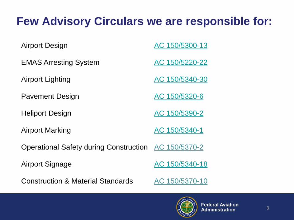
Few Advisory Circulars we are responsible for:
3
Airport Design AC 150/5300-13
EMAS Arresting System AC 150/5220-22
Airport Lighting AC 150/5340-30
Pavement Design AC 150/5320-6
Heliport Design AC 150/5390-2
Airport Marking AC 150/5340-1
Operational Safety during Construction AC 150/5370-2
Airport Signage AC 150/5340-18
Construction & Material Standards AC 150/5370-10
Federal Aviation Administration
Mitigation of Excursions
Runway Design Characteristics Runway Safety Areas Engineered Arresting System Declared Distances Distance Remaining Signs
4
Federal Aviation Administration
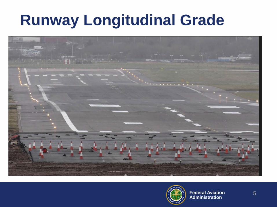
Runway Longitudinal Grade
5
Federal Aviation Administration
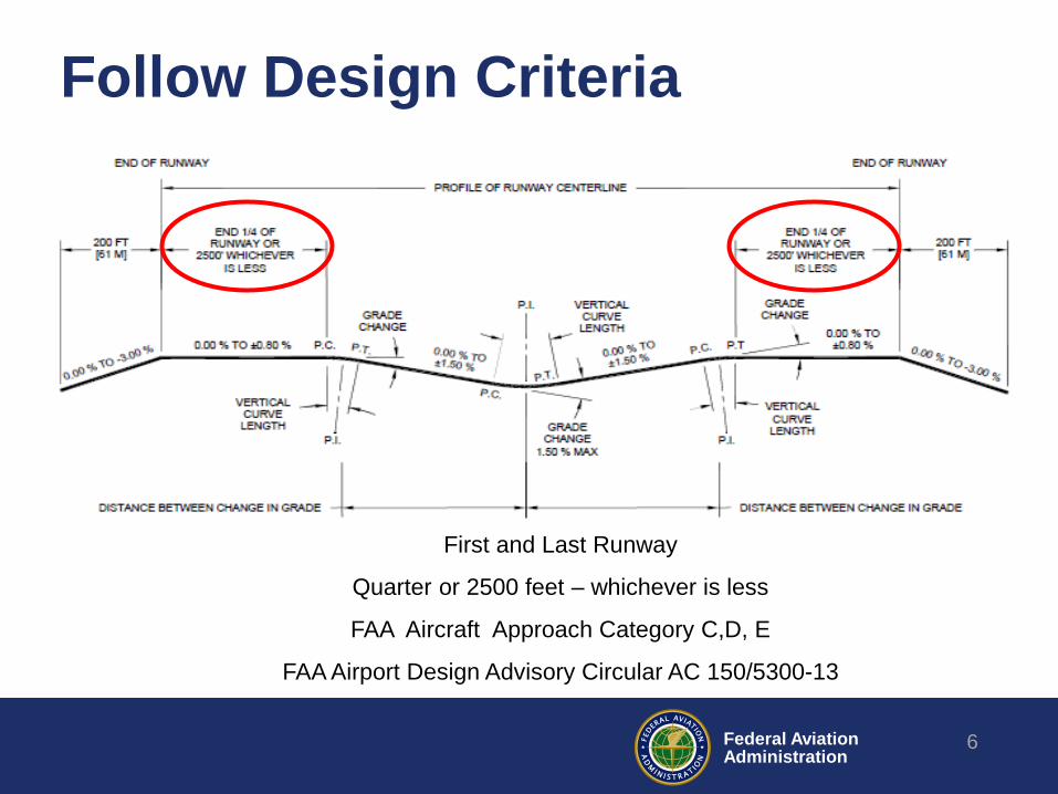
Follow Design Criteria
6
First and Last Runway
Quarter or 2500 feet – whichever is less
FAA Aircraft Approach Category C,D, E
FAA Airport Design Advisory Circular AC 150/5300-13
7 Federal Aviation Administration
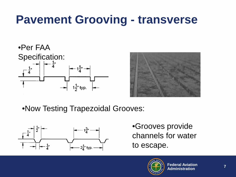
•Per FAA Specification:
•Now Testing Trapezoidal Grooves:
•Grooves provide channels for water to escape.
Pavement Grooving - transverse
8 Federal Aviation Administration
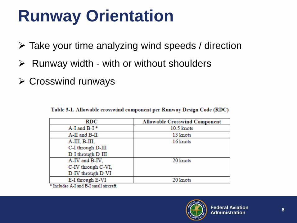
Runway Orientation Take your time analyzing wind speeds / direction
Runway width - with or without shoulders
Crosswind runways
9 Federal Aviation Administration
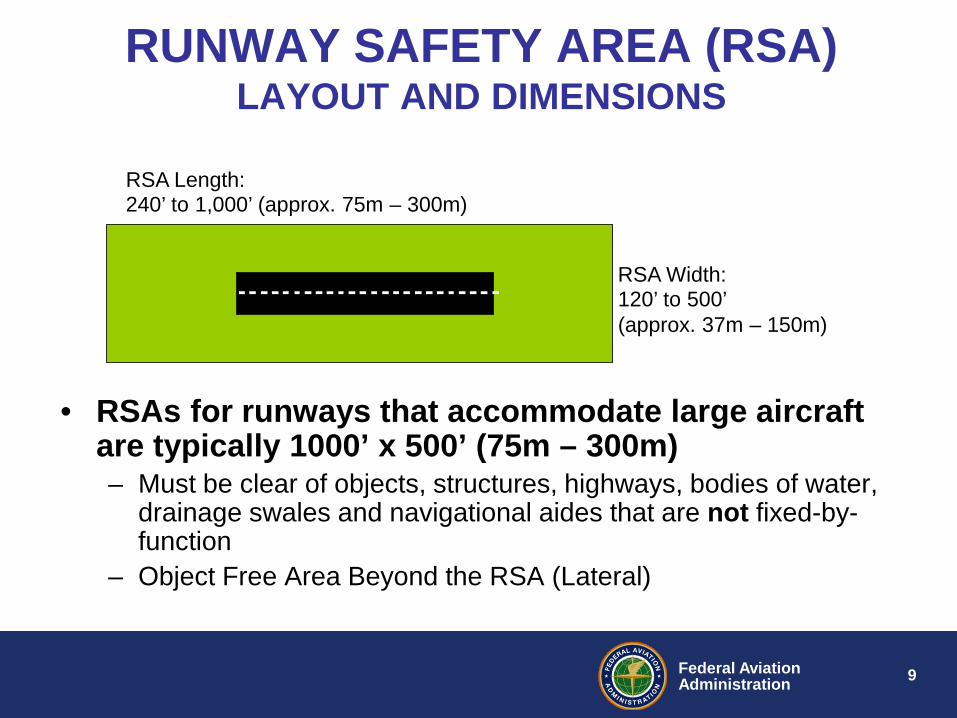
RUNWAY SAFETY AREA (RSA) LAYOUT AND DIMENSIONS
• RSAs for runways that accommodate large aircraft are typically 1000’ x 500’ (75m – 300m) – Must be clear of objects, structures, highways, bodies of water,
drainage swales and navigational aides that are not fixed-by-function
– Object Free Area Beyond the RSA (Lateral)
RSA Length: 240’ to 1,000’ (approx. 75m – 300m)
RSA Width: 120’ to 500’ (approx. 37m – 150m)
10 Federal Aviation Administration
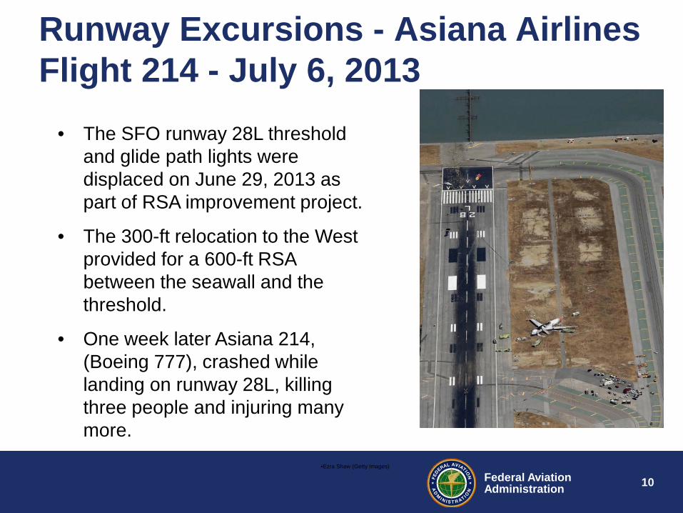
Runway Excursions - Asiana Airlines Flight 214 - July 6, 2013
•Ezra Shaw (Getty Images)
• The SFO runway 28L threshold and glide path lights were displaced on June 29, 2013 as part of RSA improvement project.
• The 300-ft relocation to the West provided for a 600-ft RSA between the seawall and the threshold.
• One week later Asiana 214, (Boeing 777), crashed while landing on runway 28L, killing three people and injuring many more.
11 Federal Aviation Administration
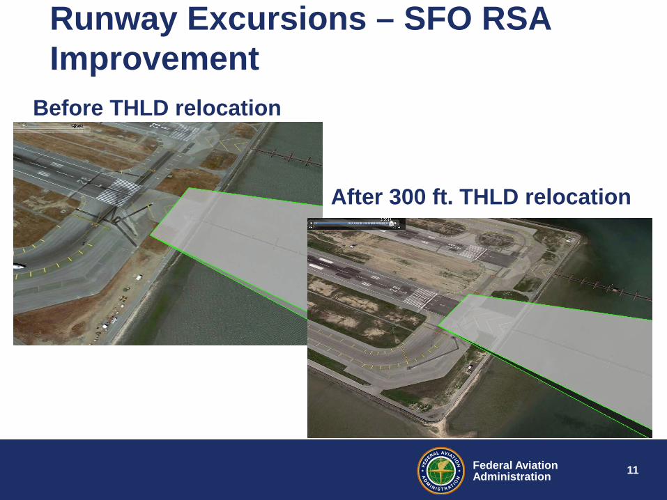
Runway Excursions – SFO RSA Improvement
After 300 ft. THLD relocation
Before THLD relocation
12 Federal Aviation Administration
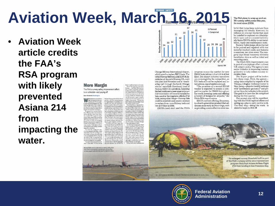
• Aviation Week article credits the FAA’s RSA program with likely prevented Asiana 214 from impacting the water.
Aviation Week, March 16, 2015
13 Federal Aviation Administration
ENGINEERED MATERIALS ARRESTING SYSTEM
• DEFINITION – A system consisting of a light bed of material placed at the end of runways that consists of “high energy absorbing materials of selected strength, which will reliably and predictably crush under the weight of an aircraft.” (AC No. 150/5220-22B)
• EMAS beds are intended to SAFELY and quickly stop aircraft that overrun runways with minimal or no damage to the aircraft
• Standard EMAS is designed to arrest with airplane entrance velocity of 70 knots
14 Federal Aviation Administration
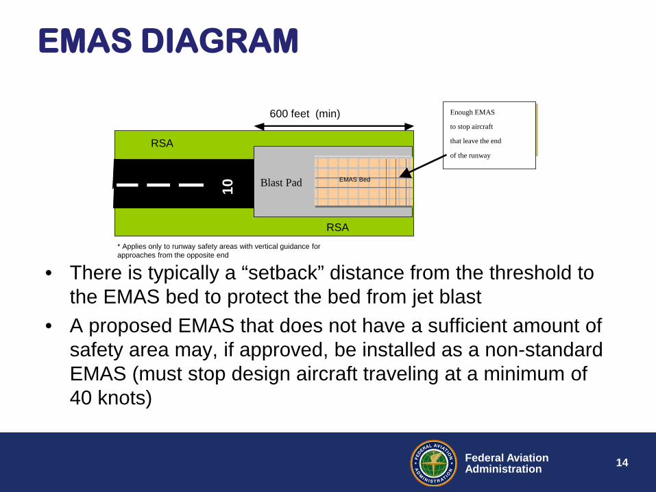
EMAS DIAGRAM
Blast Pad 10
EMAS Bed
RSA
600 feet (min)
RSA
Enough EMAS
to stop aircraft
that leave the end
of the runway
* Applies only to runway safety areas with vertical guidance for approaches from the opposite end
• There is typically a “setback” distance from the threshold to
the EMAS bed to protect the bed from jet blast • A proposed EMAS that does not have a sufficient amount of
safety area may, if approved, be installed as a non-standard EMAS (must stop design aircraft traveling at a minimum of 40 knots)
15 Federal Aviation Administration
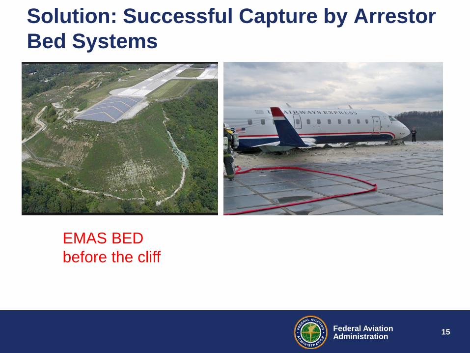
Solution: Successful Capture by Arrestor Bed Systems
EMAS BED before the cliff
16 Federal Aviation Administration
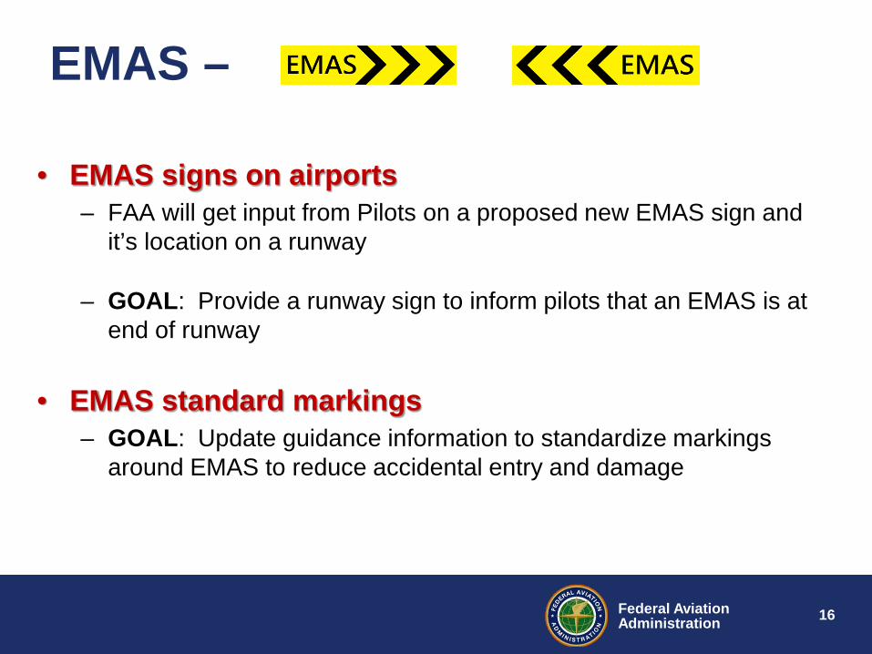
EMAS –
• EMAS signs on airports – FAA will get input from Pilots on a proposed new EMAS sign and
it’s location on a runway
– GOAL: Provide a runway sign to inform pilots that an EMAS is at end of runway
• EMAS standard markings – GOAL: Update guidance information to standardize markings
around EMAS to reduce accidental entry and damage
17 Federal Aviation Administration
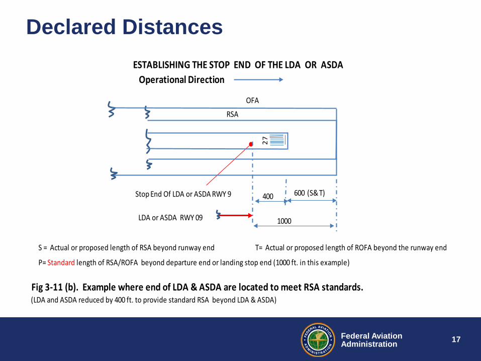
Declared Distances
S = Actual or proposed length of RSA beyond runway end T= Actual or proposed length of ROFA beyond the runway end
P= Standard length of RSA/ROFA beyond departure end or landing stop end (1000 ft. in this example)
Fig 3-11 (b). Example where end of LDA & ASDA are located to meet RSA standards. (LDA and ASDA reduced by 400 ft. to provide standard RSA beyond LDA & ASDA)
ESTABLISHING THE STOP END OF THE LDA OR ASDA
RSA
Stop End Of LDA or ASDA RWY 9 600 (S& T)400
1000
OFA
LDA or ASDA RWY 09
Operational Direction
18 Federal Aviation Administration
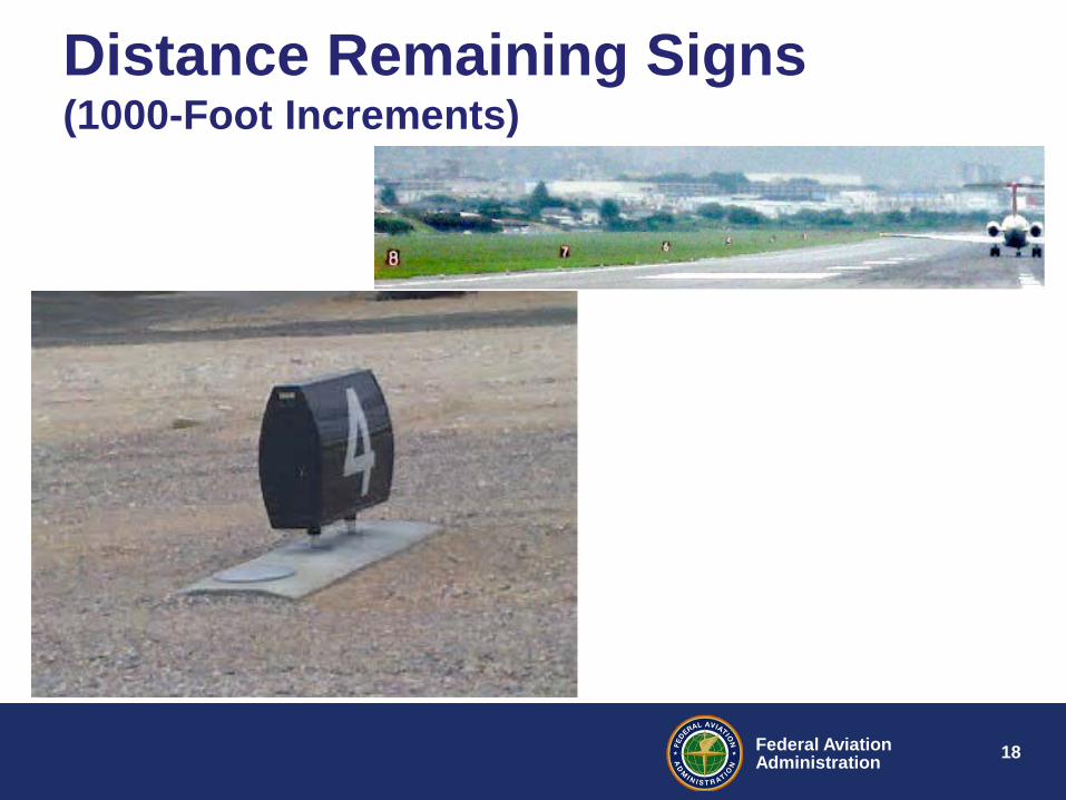
Distance Remaining Signs (1000-Foot Increments)
19 Federal Aviation Administration
Questions? Presented by: Khalil Elias Kodsi, P.E. PMP Manager, Airport Engineering Division AAS-100