Embed Size (px)
Citation preview
AD-AI?4 096 THE DESIGN OF RADIOGRAPHIC ENHANCEMENT SYS1ENS(U)BATTELLE COLUMBUS LASS OH D T HAYIFORD SEP 86NAVEODTECHCE-TR-279 NSSI?4-BS-C-SS55
UNCLASSIFIED F/6 14/5 ML
mhmmhmmhhhum
AA
11111_L25 12 1116
M ICR0P REOUIO ET HR
=AiOA BR A FSADRS16
L J
0 NAVEOTECUCEN TECHNICAL REPORT TR- 278 /
THE DESIGN OF RADIOGRAPHIC ENHANCEMENT SYSTEMS
SEPTEMBER 1988
FINAL REPORT(Contract No. NOO174-85-C--00.5i)
Di rib nI ed to G Goveue :faen" onlyst Ev u ion; Pt mbr 4.the s fori du nt m be refe d to the Ol and
ie av E Iosiv Or ance sp I Terite Indian ad MD 40-5070.
NOV2
cm,1
Prepared byU6J NAVAL EXPLOSIVE ORDNANCE DISPOSAL TECHNOLOGY CENTER
__j Indian Head, Maryland
LA... 0 p,oved
m.S ocisat has beel oe- itstot.
*,
b6 n. ut02
..:.-. , --:.-.: ... . . . . . . . .. . . . . . . . . . . . . . . . . . . . . . .. . .. . - ...*..*d.*.*.: -.-: .-,- -I
.47
DI SCLAIMER
.5The mention of commercial products or companies in this report isneither an endorsement nor an approval of such items by the U.S.
r-. Government.
." °
LA."LLA .
Released by Under Authority fLIONEL A. DICKINSON L. M. KELLY, CDR USN -
Technical Director Commanding Off ic r
i .~~ ."5.
- 5 . . - '. . .. ... -...,~. i.- J. *.-..*-5--5.'-
Lk~ X V'k ... -- 'S W- - -
REPORT DOCUMENTATION PAGEla. REPOR7 SEC*JR17Y C.ASSFiCATiON ~oRES7RIC:VE MARKINGS ~ qUNCLASSIFIED NA
2a. SEC~jR!Tv C..ASSi;ICATION AUTHOR!TY 3 :)S7RIBU71ON i A,/AiLA31-.7Y OF RE-POR7NA
10. 0EC-ASSiZC.A~i0N 'OWNGRAL~GSHDL UNLIMITED ' %
~ :::~~ ONIIZATION REDOR'r NUMBER(S' -.MNORiNG ORGA%:ZAT!ON rEO. VE'(S %
TR-278 NOOl 74-85-0-00551
6a. NAME OF PERFORMING ORGANIZA71ON 6o OFFICE SYMBOL 7a- NAME OP MONITORING ORGANiZA7ION V.
Battelle Columbus Laboratories (fap/cbe NAVEODTECHCEN -'
6-ADDRESS (Crty, State. and ZIP Code) 7b. ADDRESS (City, State, and ZIP Code) '
Columbus, Ohio 43201-2693 Indian Head, MD 20640
Ba. NAME OF :UNDINC.'SPONSORING 3b. OF* iCE SYMBOL 9. PROCUREMENT INSTRUMENT IDENTIFiCATION NUMBER2ORGANIZATION 11f applicable)
NAV EODTECHCEN ________ N00 174Sr- AD DR E 3 (City, Sta te. and ZIP Code) 10. SOURCE OF FUNDING NUMBERS
PROGRAM IPROjECT 7 ASK IWORK '.IN:-IninHaMD 20640 ELEMENT NO. NO. NO 1ACCESSiON NO
1' ,nc;uae Secury CidasficatIon)
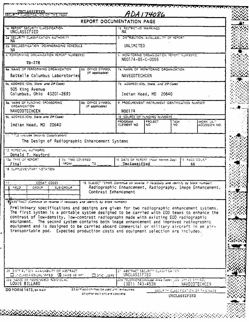
The Design of Radiographic Enhancement Systems
.2 02RSO%.A-. AUTH4OR(SM
Donald T. Hayford~~3a.~?0 7!S0R~O7j2 ME rOEED[ DATE OF REPORT (Year Monfri. Day, 5 AQE: CO.%-
Final I' ROM~ TO I Unclassif ied 66
'6. SU~n WEJA".07A7IONI
17COSATI CODES ',8 SUBJEC- "EM Contnue on reverse if n~ecessary and iaer'rfy by olock nuwhoer) jI FELD G-ROUP SUB-G-ROUP Radiographic Enhancement, Radiography, Image Enhancement,
_________________I__ Contrast Enhancement
ANB-ACT (,C-nrinue on reverse if necessary and idenrtify by block number)
Preliminary specifications and designs are given for two radiographic enhancement systems.The first system is a portable system designed to be carried with EO teams to enhance the '~
contrast of low-density, low-cont -rast radiographs made with existing EOD radiographicequipment. The second system contains both image enhancement and improved radiographicequipment and is designed to be carried aboard commercial or military aircraft in an air-transportable pod. Expected production costs and equipment selection are includei.
z'XW~
% .p 0
20 0 ;~ C.AALAIT A3SRAC' 21 ASRAC7 SECRi-v C~i;3 CA'O~ .'S; 0'N.IE iA/-E AS ;RP- 10 :); 'S UNCLASSIFIED
2za. %Ami:- IE F ::-S'8LE INDIVI:)i.AL 2 2o 7E. L P ON E (Iricluae A.red a oo) .: 2:c E$'5).LOUIS BILLARD (301) 743-4538 NAV EOCTECHCEN
OD FORM 1473,84 MAR Z3 S~ DAIC-Ea e sa~tera~~d-v-Ail otler ec.:ons are cooicete NLSIED'
N W VV 0A
TABLE OF CONTENTS
ACKNOWLEDGEMENTS. .. ...... ...... ...... ....... 1
SUMMARY. .... ...... ....... ...... ........ 2
INTRODUCTION. .. ...... ...... ...... ......... 3
DESIGN OF SYSTEM I .. .... ...... ...... ......... 6 ~
System I Functional Specifications .. ...... ........ 6
The Computer .. ...... ...... ...... ...... 8
Video Digitizers . . . . . . . . . . . . . . . . . . . . . . 9
Spatial Resolution .. .... ...... ...... ... 11
Gray-Scale Resolution .. ...... ...... ..... 11 ~ .
Software Requirements .. ...... ...... ..... 16
Available Software .. .... ...... ...... ... 16
Video Cameras. .. ...... ...... ...... ..... 18
Logarithmic Amplification of the Video Signal ... .... 21
The Light Table. .. ...... ...... ...... .... 21
Recommended Equipment .. .... ...... ...... .... 22
System I Cost .. ...... ...... ...... ... 22
Notes on Packaging .. .... ...... ...... ... 23
DESIGN OF SYSTEM II .. ....... ...... ...... .... 24
System Iha Functional Specifications. .... ...... .. 25
Additional Specifications for System Ib ..... ........ 29
System II Hardware .. ...... ...... ...... ... 30
X-Ray Unit. .. ...... ...... ...... .... 30
Radiographic Films .. .... ...... ...... ... 31
.34
Image Intensifier . . . . . . . . . . . . . . . . . . .
A
N N
TABLE OF CONTENTS(Continued)
Page
Additional Equipment for System lib ............... .... 33
Image Digitizer and Recorder ...... .............. 34
Image Processor ...... .................... ... 35
System Ila Costs ....... .. ............... ..... 40
System lib Costs ....... .. ...................... 40
CONCLUSIONS AND RECOMMENDATIONS .... ................. .... 41
APPENDIX A
Image Processing Software for theImaging Technology Frame Grabber ................ . . ... A-i
LIST OF TABLES
Table 1. Video Digitizer ....... ... ... .... .... 10
Table 2. Smallest Discernible Density Differences ......... 15
Table 3. Measured Camera Resolutions . . ..... .... .. 20 '-..
LIST OF FIGURES
Figure 1. Artist's Sketch of the Components of System I . . . . 6
Figure 2. Digitized Gray-Scale Values Versus FilmDensities for Three Camera Iris Settings ... ...... 13
Figure 3. Artists's Sketch of the Components of System lib . 26
Figure 4. Artists's Conception of System libin the Air Transportable Pod .......... 27
Figure 5. Print of Original Unenhanced NegativeScanned with the P-1700 . . .. ........... ..... 36
Figure 6. Print of Digitally Enhanced Image in Figure 5Recorded on the P-1700 . .. ..... ... .... 37
I. B,v,
, , ".
s r* * . % , £,%-',#
\W..~iy ry ~r -,- - . ,.-
-. '00 0 I
ACKNOWLEDGEMENTS
The author would like to thank the distributors and manufac- aturers who generously lent us equipment for evaluation. These are
Mr. Terry Fritz, Applied Data Management, Cincinnati, Ohio
Mr. John Binkley, Miltronics Digital Hardware, Columbus,
Indiana
Mr. Gary Fullerton, Jaynes-Elkro, Columbus, Ohio _*'
Mr. Virgil Davis, Dage-MTI, Detroit, Michigan :.
. . .% -_
Just if I cet!
ByDi< st r ibut i. on/ * -
0 Avaiiai tv Codes -0. .
- -Ava'.:1 and/oriDi -t Special ....4A
Distribution Statement A is correct for thisreport.Per Mr. Louis Billard, NAVEONTECHC"
. o-.. w. V* .,
°. %
i°p . .
. . 'F*,*.* ~% . :-. * ~-. . * %- . -.-
SUMMARY
Explosive ordnance disposal (EOD) teams use radiographic
techniques to determine the inner structure of improvised explosive
devices (IED's) prior to dearming them. The conditions under which the -
raaiographs are made are often far from ideal. As a consequence, the
resulting radiographs may be poorly exposed, making it difficult to raccurately ascertain the interior of the device. 3ecause of the type offilm and radiographic equipment that EOD teams normally use, most of the ''
poor radiographs are overexposed, giving rise to radiographs which have
low film densities as well as having low contrast.
In a previous project1 conducted for the Naval EOD Technology
Center (NAVEODTECHCEN), a variety of ways to enhance the contrast of low-contrast, low-density radiographs were examined. Several recommendations
were made at the conclusion of that project. One was that digital
contrast enhancement techniques should be used to enhance low-contrast
radiographs to allow the EOD teams to discern features even in poor
quality radiographs. Another was to improve the radiographic capability
of EOD teams by using better films and equipment. 17,
As a result of that project, this project was conducted to.4..
design two radiographic systems for NAVEODTECHCEN. The first, calledSystem I, uses existing EOD radiographic techniques and equipment but
includes a portable image enhancement system to perform simple types of
contrast and image enhancement of poor quality images. System II is a 4.
larger, more complex system and includes both a digital enhancement -4system as well as improved radiographic equipment, all housed in an
air-transportable pod. System I is expected to cost around $10,000 inproduction versions and System II may cost between $150,000 and $400,000
depending on the exact configuration selected. Specific equipment
recommendations for each system are included in this report. V.
1 IMAGE ENHANCEMENT OF LOW-CONTRAST, LOW-DENSITY RADIOGRAPHS, April i,1984, Contract N00174-83-C-021,
i i '4 .'.
4.
o.
INTRODUCTION
Radiography is a technique cummonly used by DoD EOD teams to
determine, in as much as possible, the inner workings of improvised
explosive devices (IED's) prior to dearming them. Unfortunately, many of
these IED's are situated in ways that often prevent the disposal teams
from making high quality radiographs. For example, lIED's may be located
in lockers, next to walls, or may be encased by an unknown thickness of
ste& or other dense material. As a result, making radiographs which are
properly exposed and present a clear picture of the interior features of
the IED is difficult.
Current EOD practice is to use a MK-32 150 kV flash X-ray
unit with a Polaroid film cassette to make the radiographs. Inside thefilm cassette is a rire-earth fluorescent intensifying screen to allow
the film to respond to the beam of X-rays generated by the flash X-ray
unit. In general, this is a good system for EOD teams; it is portable,
%"
w% %,S
,° S.°
.,.,
• "°-° ' -'
easy to use, reliable, and is capable of making good quality radiographs
under the right conditions. Moreover, the exposed film can be developed
and viewed witnin several minutes of the exposure. But this system also
has several drawbacks. First, the energy of the X-ray beam is fixed andcannot be lowered to enhance small differences in object density as can
. be done with conventional hot-filament radiographic systems. Second, thefilm density range of the Polaroid film is limited; as a consequence, the
X-ray exposure must be controlled reasonably well to make a good image.* And third, the use of intensifying screens, necessary to expose the film
with a flash X-ray unit, introduce graininess which reduces the clarity
of the image.
Despite these drawbacks, the major problems faced by EOD
teams are the inability to properly position the X-ray source and film ""with respect to the subject (since they are prevented, by the nature of *.
the subject, from moving it) and a lack of knowledge of the interior of -
the subject which would allow them to correctly set the exposure. And,
of course, there is a strong deterrent to not making several radiographs
of IED's to obtain the correct exposure, since making the radiographs
requires that someone work in close proximity to the explosive device.
There is no solution to these last two difficulties, so ways
must be sought instead to improve both the flexibility and capability of" the radiographic systems used by EOD teams. One way is to provide a .-0
means of enhancing low-contrast (improperly exposed) radiographs in aportable package that can be carried by EOD teams. A second way is to
provide EOD teams with better radiographic equipment that will allow morelatitude in X-ray energy and exposure levels, yet still make acceptable
images.
In a previous research program, various methods by which EOD
teams could improve their radiographic capabilities were describea.
Three recommendations made were:
(1) use digital techniques to enhance
contrast of low-contrast, low-density
radi ographs
.2• 2 2"iU-"i
• * .; , '€( 2 , ,.' ': * '.: .' .' ".i - , ' ': . '. " ' '. '. .- .- ¢ . .. * .. A .. A A k . L
(2) use better radiographic films, where
possible, with larger available
density ranges
(3) use better X-ray machines, where
possible, to improve radiographic
performance.
Using these recommendations, two enhancement systems have
been designed for EOD teams. The first, System I, is built around a
portable personal computer with a video digitizer and can enhance the
contrast of low-contrast radiographs made using the existing radiographic
equipment of EOD teams. System I is comprised of two boxes, each of
which can be placed under the seat of an airplane. One box contains the
computer and video digitizer, while the other box contains a video
camera, light source for backlighting Polaroid radiographs, and miscel-
laneous hardware. The expected cost of a production version of System I
is in the neighborhood of $10,000. In a production lot of 300, the
economics of scale would reduce the per unit cost by 10 to 15 percent.
System II contains not only digital image .I
processing/enhancement hardware, but also contains a larger (320 kV)
X-ray machine, a variety of radiographic films, an image intensifier, and
a film developer. System II, because of the types of equipment used, is
not designed to portable but is contained in an air-transportable pod
instead. Once transported to the site, the pod opens to form a working
area for EOD teams. Because of the larger X-ray machine, System II can
be used to penetrate over one inch of steel, as opposed to the nominally
0.25 inches for System I.- And because the energy of the X-rays emitted
by this machine can be adjusted anywhere from 32 kV to 320 kV, System II
can also be used to make high contrast images of less dense objects.
Actually, two versions of System II were designed. The
first, System Ila, uses System I as the image processing/enhancement
system, while the second, System lIb, uses a far more powerful, and
expensive, image digitizer and processor. It is believed that the
combination of the improved radiographic capability with the image
processing capability of System I (i.e., System Ila) will solve the
majority of problems faced by EOD teams -- at less than nalf the cost of
'. 3
-a .5 5 ..
".b .' i. a :
• .- -. % ...' ,.. ., .' .. -.. - .. . .,- . . .,- ,- /. ... . .,,, . . .,, ,- .. J¢._, ., . ,# ,. - . . . ... .. ..
* System Ilb. The expected cost of a production version of System Ila is
about $150,000, while that for System lIb is nearly $400,000.This report documents the design considerations for both
Systems I and II. Evaluations of hardware and software available for
System I and hardware for System II are included.
64
J, -P
,.. -b
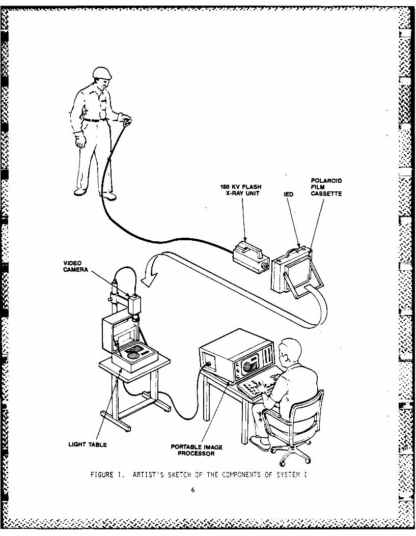
DESIGN OF SYSTEM I
System I is a portable image processing unit designed
primarily to work with radiographs made with the MK-32 flash X-ray unit.
System I consists of four basic elements, a portable computer, a high--
speed image digitizer, a video camera, and a light table for illuminating
the Polaroid radiographs made with the MK-32 unit. The image digitizer q
fits inside the portable computer, while the video camera is packed into
the light table during transport. An artist,s conception of the system
in operation is shown in Figure 1.
The functional specifications for System I are listed in the O
next section. Following that are reviews of the hardware evaluated for
System I and the final equipment recommendations and costs.
System I Functional Specifications a
Purpose: The primary purpose of Radiographic Enhancement System I is
to enhance the contrast of low-contrast and/or low-density
radiographs made using current NAVECOTECHCEN radiographic
practices.
I. The image source is Polaroid TPX film. Film size isapproximately 8.5 x 11 inches (21.6 x 27.9 cm). Image
size is approximately 7.5 x 9.5 inches (19.1 x 24.1
cm). Image density range is approximately 0.1 to 3.0.
2. The image sensor shall be a video camera with either a
CCD array, newvicon, or vidicon. The latter two are
preferred. The resolution of the camera must be greater
than 512 optical lines in the horizontal dire.ction and
350 optical lines in the vertical direction.
3. The image source (Polaroid film) shall be illuminated
evenly with sufficient light to generate a usable image
I within the density range specified above.
5
p...'-
'S 'v
POLAROI
150 K FLAS FIL
X-RAYUNIT ED CASETT
aVIDE
IHT \AL PORTBLRMAGXPRYONICEESCSSTT
FIUE1 RITS KTHO H OPOET FSSE
6'
1*,
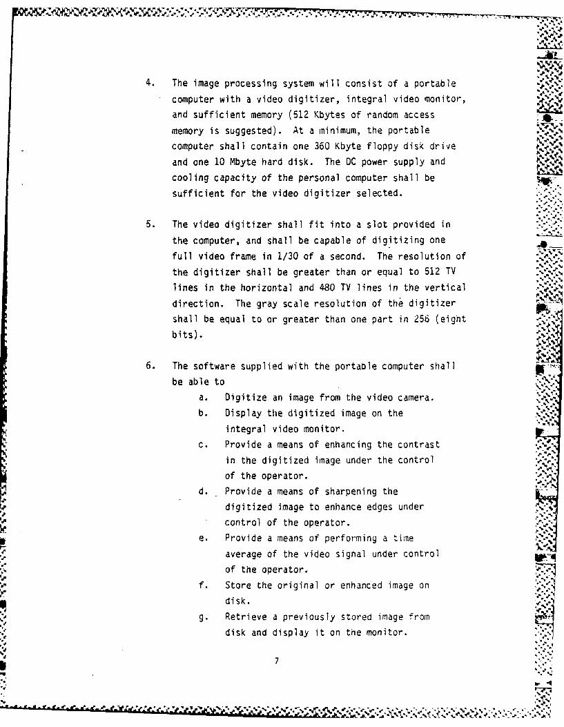
4. The image processing system will consist of a portable
computer with a video digitizer, integral video monitor,
and sufficient memory (512 Kbytes of random access
memory is suggested). At a minimum, the portable
computer shall contain one 360 Kbyte floppy disk drive
and one 10 Mbyte hard disk. The DC power supply and
cooling capacity of the personal computer shall be
sufficient for the video digitizer selected.
5. The video digitizer shall fit into a slot provided in
the computer, and shall be capable of digitizing one
full video frame in 1/30 of a second. The resolution of
the digitizer shall be greater than or equal to 512 TV
lines in the horizontal and 480 TV lines in the vertical -
direction. The gray scale resolution of the digitizer
shall be equal to or greater than one part in 256 (eight
bits).
6. The software supplied with the portable computer shall
be able to
a. Digitize an image from the video camera.
b. Display the digitized image on the
integral video monitor.
c. Provide a means of enhancing the contrast
in the digitized image under the control
of the operator.
d. Provide a means of sharpening the
digitized image to enhance edges under
* control of the operator.
e. Provide a means of performing a tine
average of the video signal under control
of the operator.
f. Store the original or enhanced image on
disk. "
g. Retrieve a previously stored image from
disk and display it on the monitor.
7
e-I d
.% .. .. * %.- 1~% .
7. The image processing software described above shall be -7
easy to use and require minimal training for the
operators.
8. The entire image enhancement package shall fit into two
packages which are suitable for under-the-seat storageon board a commercial airliner.
The Computer.4-,.
Several contrast enhancement techniques discussed in the last-report
2 , such as reproduction of the radiograph with a high-contrast
film, could be used to enhance the contrast of EOD radiographs. However,all of the nonelectrical methods are extremely sensitive to slight "
variations in processing conditions and require several iterations before .4
a good image can be made. Digital contrast enhancement also requires
several iterations, but the time required to complete one iteration is -
very small, so that a large number of trials can be made in less time _4
than one trial of the nonelectrical methods. ..
For this reason, it was recommended that electrical (more
particularly, digital) methods be used to enhance the contrast of low-contrast radiographs. Two possibilities were examined. The first was to
use a dedicated image processing system such as the Hughes 3 794, while
the second was to use a general purpose computer with added hardware and
software to perform the image processing. The decision to use the second
method was prompted by both cost and flexibility. The general purpose .%K.
computer, since it can be programmed, can perform a variety of image Lprocessing functions, though admittedly in a much slower fashion than can .
be achieved with the dedicated image processing hardware. Moreover, the
dedicated systems cost $5,000 to $10,000 more per unit than does a system'
2See 1 above.
3 Huges Aircraft Company, Image and Display Products, 6155 El Lamino .4-.
Real, Carlsbad, CA 92008
8%.
8 b _ 4
built around a general purpose computer. If this cost is multiplied by
the 300 systems expected to be bought for EOD teams, the savings are
significant.
All personal computers are built around one of the many
families of microprocessors such as the Zilog Z-80, the DEC LSI-11, or
the Intel 8088/8086. However, if the constraints of portability and
ready availability of add-on hardware and software are imposed, the
IBM-PC class of computers, built around the Intel 8088, are the obvious
choice. In this class are several varieties of portable computers. The
Compaq4 line is favored because of its reliability and compatibility with
the IBM-PC. Of these, the Compaq Plus, with an integral monitor, 10
Mbyte hard disk, and 360 Kbyte floppy disk, is the best choice. The
Compaq Plus normally has 256 Kbyte of system memory (RAM) which should be
supplemented with an additional memory board containing 384 Kbytes of
RAM, for a total of 640 Kbytes. One vendor for the memory board is
Quadram5. After the addition of the memory board, the Compaq Plus has
four slots for other add-on boards. One of these will be used for
the video digitizer.
Video Digitizers
In the course of this program, three video digitizers were. ~evaluated for their suitability as a part of System I. All of these ..
digitizers are on single printed circuit cards which can be plugged*
directly into an IBM-PC or a look-alike such as the Compaq. The three
boards are manufactured by Imaging Technology6 , Datacube 7, and Coreco 8 .
The nominal characteristics of each board are given in Table 1.
77070
7 4 Compaq Computer Corporation, PO Box 30, 19515 FM 149, Houston, TX _
5 Quadram Corporation, 4357 Park Drive, Norcross, GA 30093
6 Imaging Technology Incorporated, 600 West Cummings Park, Woburn, MA 'N
01801
7 Oitacube, Inc., 04 Dearborn Road, Peabody, MA 01960
8 C~reco Inc., 547 St. Thomas, Longueuil, Quebec, Canada J4H 3A7
9
S.I",, . % . . ,. . - . % % .,, . -.- . . . .d- . - ,. , - - .,, - ,. - ..- , .S- .-. - . . , . . • • • % .
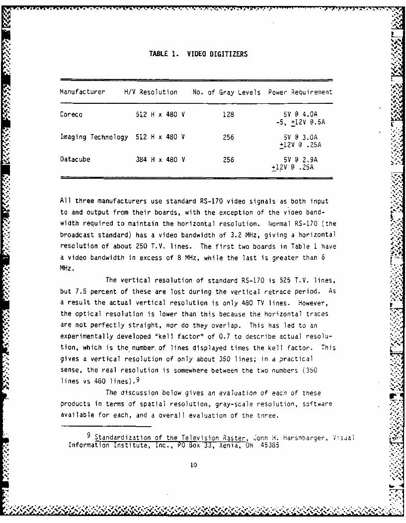
TABLE 1. VIDEO DIGITIZERS
Manufacturer H/V Resolution No. of Gray Levels Power Requiremient
Coreco 512 H x 480 V 128 5V @ 4.OA-5, +12V @.5A
Imaging Technology 512 H x 480 V 256 5V @ 3.OA+12V @ .25A
Datacube 384 H x 480 V 256 5V @ 2.9A+12V @ .25A
V.°
All three manufacturers use standard RS-170 video signals as both input
to and output from their boards, with the exception of the viaeo band-width required to maintain the horizontal resolution. Normal RS-170 (the ...
broadcast standard) has a video bandwidth of 3.2 MHz, giving a horizontal
resolution of about 250 T.V. lines. The first two boards in Table 1 have
a video bandwidth in excess of 8 MHz, while the last is greater than 6
MHz.
The vertical resolution of standard RS-170 is 525 T.V. lines,but 7.5 percent of these are lost during the vertical retrace period. As
a result the actual vertical resolution is only 480 TV lines. However,
the optical resolution is lower than this because the horizontal traces
are not perfectly straight, nor do they overlap. This has led to an
experimentally developed "kell factor" of 0.7 to describe actual resolu-tion, which is the number-of lines displayed times the kell factor. This L-gives a vertical resolution of only about 350 lines; in a practical
sense, the real resolution is somewhere between the two numbers (350lines vs 480 lines). 9 F,
The discussion below gives an evaluation of each of these
products in terms of spatial resolution, gray-scale resolution, software
available for each, and a overall evaluation of the three.
9 Standardization of the Television Raster, donn H. Harshbarger, VisialInformation Institute, Inc., PO Box 33, Xenia, OH 45385
10
products in terms of spatial resolution, gray-scale resolution, software
available for each, and a overall evaluation of the three.
Spatial Resolution a-
The RS-170 video standard calls for a 4:3 aspect ratio in the
displayed picture; that is, the horizontal size of the viewed image is
1.33 times the vertical size. Using this figure, the approximate spatial
resolution of the different boards can be predicted. Of course, the
actual resolution may be somewhat lower than predicted, depending on the .'.-
video camera used, the lighting conditions, and the contrast in the
image.
If a 5.12 inch (13.00 cm) wide image is viewed with a video
camera, the vertical size will necessarily be three-fourths of this "S.
(because of the 4:3 aspect ratio) or 3.84 inches (9.75 cm). Thus, the
maximum horizontal resolution will be 0.010 inches (0.254 mm) for the two
boards with 512 pixels in the horizontal direction, while the vertical
resolution will range between 0.011 and 0.008 inches (0.279 mm and 0.203
mm). Thus for these boards, the resolutions in the two directions are fabout equal. On the other hand, the Datacube board, with only 384 pixels. *;"
in the horizontal direction, has a maximum horizontal resolution for the
same image of only 0.013 inches (0.330 rm), perhaps as much as 60 percent..,4
greater than the resolution in the vertical direction. To achieve the
same resolution as with the other two boards, the image size must be
reduced to 3.84 inches (9.75 cm) by 2.88 inches (7.32 cm). Thus, the .
Imaging Technology and Coreco boards can view almost 80 percent more area
with the same efficiency as the Datacube board. All other things being
equal, the Imaging Technology and Coreco boards are recommended over the
Datacube on the basis of spatial resolution. .
The resolution of the Imaging Technology board was measured
with a Oage-MTI NC-65 camera attached (see the section below on Video W7
Cameras), using a standard NBS resolution chart. This chart contains
black horizontal and vertical lines of various spacings on a white
background. The measured resolutions were 400 optical (not TV) lines in
the horizontal and 370 lines in the vertical direction. The measured
resolution in both directions is only about 78 percent of the theoretical
71
.°°5*
maximum, attributable to electrical noise, vibration of the camera, and
the somewhat subjective nature of the measurement.
Gray-Scale Resolution
The analog video signal from the video camera ranges from .
0.35 volts, representing "full black", to 1.0 vol'ts, representing "fullwhite". This signal is digitized by the video boards to a give a number
representing the video signal level; these numbers can range from 0 to
255 in the case of the Imaging Technology and Datacube boards, and 0 to
127 for the Coraco board. Thus, for the Imaging Technology and Datacube
boards, each increment (from 0 to 255) corresponds to a change of 2.54 mV
in the analog video signal, but represents a change of 5.08 mV for the
Coreco board.
For most video cameras, the definition of "full black" and
"full white" depends on the image being viewed, the iris opening, the
sensitivity of the light sensor in the camera, and perhaps, the gains of
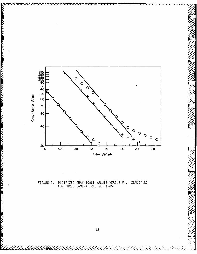
various electronic amplifiers in the camera or digitizer. Shown inFigure 2 are three curves relating film density to digitized gray-scale I-value for a Sony CCD camera with the Imaging Technology digitizer for
three different light level ranges. fote that the scale for the aray-
scale is logarithmic.
Since film density is defined as the logarithm of the
fraction of transmitted light intensity, while the gray-scale value is
roughly proportional to the light intensity, a plot of gray-scale value
versus film density should be linear on a semi-log plot. Indeed it is,
at least until the gray-scale value drops below about 30, where a
noticeable tail develops (due to offsets in the camera electronics). The.* slopes of all three curves should be the same, and again, they are
approximately so. The equation for gray-scale value (G) as a function offilm density (D) is given by w
log G K + mD ')
where K is some constant (determined by, among other things, the lensiris on the camera) and m is the slope of the curve. Generally, m is
12
4E
4,~ 4 ~. 4. . ~. '4 ,,. 4.4, . .* % ~ 4 ~~( . ~% 44 4. . . ~ **~A ..~*~,.. '-*-,4
UP*Nw 6ik LwwlX 9.7k r M -o -_v - W4 71 -. I_. -Pc-
'4-
,p-
4 4
200- 0180- 0160 - 0140
4 120
100-
~ 80 1,
o2
60.
o
..- 4 -
40- 000 00
+ 00++ 0o
200 0.4 0.8 1.2 1.6 2.0 2.4 2.8 r
Film Density -
%',
FIGURE 2. DIGITIZED GRAY-SCALE VALUES VERSUS FILV DENS1TIESFOR THREE CAMERA IRIS SETTINGS
.13-:'.4-'
*p %
"5
13
4
. "
'p-
. - .% . ,% % % % •% , .% . • , % . , , .. . % . . . - - . .
"'p : Zi ' ,,
;; z . z ,.'.'> ,.zr -,,...-.:
.- "-',--'.- . ..-
- . .-. - -. - " --.-
J -
-. .
. . . . . . . --- .. ' ' . :'''..-._ _ _'..-
- ' t. . . . "_
SI., . -.
fixed for a particular camera, though some cameras will allow m to be
adjusted. For the camera used in Figure 2, m is approximately -0.63.
To measure the sensitivity of the digitizer board to changes
in film density, the derivative dG/dD is computed from Eq. 1, as
dG/dD = 2.3026m(K + mD) (2)
or
dG/dD = 2.3026mG (3)
Note that the rate of change of gray-scale with respect to film density
depends on only two things, the gray-scale value and the camera con-
stant. In this section, the discussion is concerned only with the
digitizer boards, and the value for m will be treated as a constant. To
evaluate the sensitivity to density changes it is noted that
AG/AD = dG/dD (4)
. or
AD A AG/2.2036mG (5)
Since the gray-scale levels can only change in discreet levels of one,
then smallest density difference than can be discerned is
AD = 0.4343/mG (6)P J
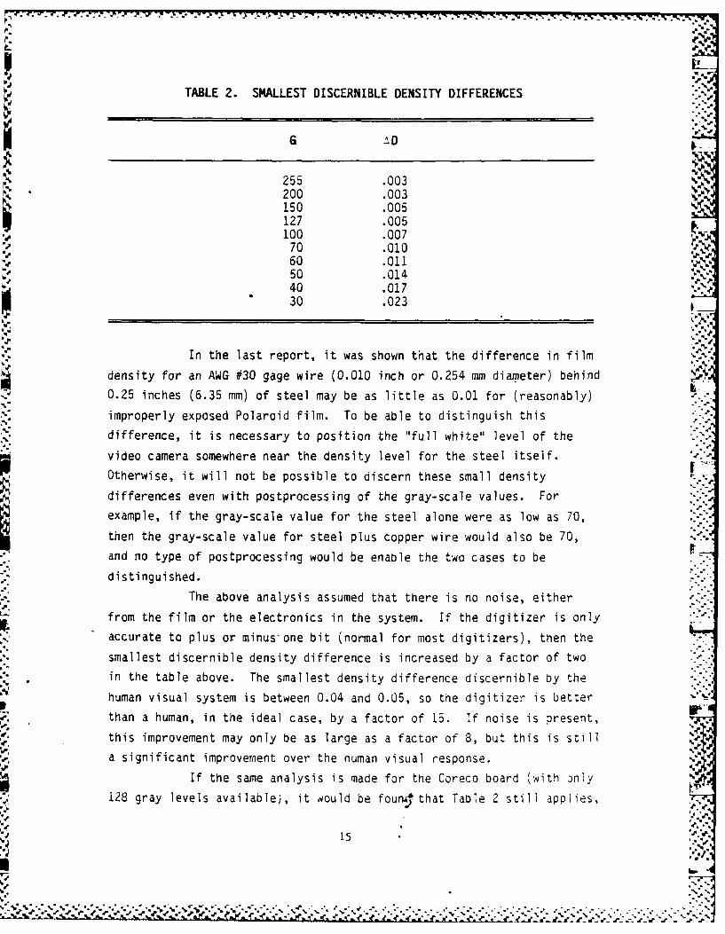
Table 2 shows the smallest discernible density difference for various
gray-scale values using the straight-line approximation to gray-scale vs
density curve. The actual ,D's are a little larger for gray-scale values
less than about 40, because of the tail in the curve.
14
,.°
'a *-
04
TABLE 2. SMALLEST DISCERNIBLE DENSITY DIFFERENCES-'
G 2
1: 255 .003 200 .003150 .005127 .005100 .007
60 .011,.,50 .014 '40 .017
30 .023
In the last report, it was shown that the difference in film
density for an AWG #30 gage wire (0.010 inch or 0.254 mm diameter) behind0.25 inches (6.35 mm) of steel may be as little as 0.01 for (reasonably)
improperly exposed Polaroid film. To be able to distinguish thisdifference, it is necessary to position the "full white" level of the
video camera somewhere near the density level for the steel itself.
Otherwise, it will not be possible to discern these small densitydifferences even with postprocessing of the gray-scale values. For
example, if the gray-scale value for the steel alone were as low as 70,
then the gray-scale value for steel plus copper wire would also be 70,and no type of postprocessing would be enable the two cases to be
distinguished.
The above analysis assumed that there is no noise, eitherfrom the film or the electronics in the system. If the digitizer is onlyaccurate to plus or minus-one bit (normal for most digitizers), then the
smallest discernible density difference is increased by a factor of two
in the table above. The smallest density difference discernible by thehuman visual system is between 0.04 and 0.05, so the digitizer is better
IIthan a human, in the ideal case, by a factor of 15. If noise is present,this improvement may only be as large as a factor of 8, but this is stilla significant improvement over the numan visual response.
If the same analysis is made for the Coreco board (with onlyi128 gray levels available), it would be found that Table 2 still applies,
15
except that the gray-scale values are limited to 127 or less. Thus for
this board, the minimum discernable density difference (with noise) is
around 0.01, just adequate for the case of the wire behind steel.
On the basis of gray-scale resolution, the Imaging Technology
and Datacube digitizers are superior to the Coreco. Moreover, thedifference in gray-scale resolution is important for this application. .,•"°
Software Requirements
The primary function of the software for System I is to allowthe operator to enhance the contrast of video images. Other image
processing functions will also be useful. Among these are-edge sharpen-
ing to visually enhance thin objects such as wires, and time averaging
the video signal to improve the signal-to-noise ratio and give a much
cleaner image. Other useful functions not related to image processing
are storing an original or processed image on disk or retrieving a stored .ZAimage for further processing or review.
Software written by Battelle for the purposes of evaluating .
the Imaging Technology digitizer is included as Appendix A. Though not
strictly intended to be easy to use, it contains most of the necessary
functions and may be used as a guide to future software development. ...
Available Software
According to the manufacturers of all three digitizer boards,
software can be supplied to operate their boards. This software is free
with the Oatacube board and available at an extra cost for the other
two. It was possible to evaluate the software for the Datacube and the
Imaging Technology boards. The software was not available (not yet
written) for the Coreco board at the time of evaluation.lBatacube-Supplied Software. The software suppliea by
Datacube included a demonstration program along with several subroutines
written for the Lattice C compiler10 . These subroutines are used to
"setup the digitizer and acquire images. No image processing or contrast
10 Latice, Inc., PO Box 3148, Glen Ellyn, IL 60138
16
• , -TI.-.T
€' " • • #' #" €' .' .' ." % .- o .. ,., . . . . . . . . . . .. . .. . . . _ _ _
b.~~~1 -. , . .
enhancement routines are supplied. Except for the routines which
actually operate the board, all software for System I must be written.
Imaging Technology-Supplied Software. Unlike Datacube,S
Imaging Technology will supply a complete software package with their
board (at a cost of $995). Their package is touted in the trade journals
as the best available for the IBM-PC class computers. The author was ' p
supplied with both Version 1 and a preliminary copy of Version 2.
Imaging Technology plans to provide a complete set of subroutines which
can be integrated into a developer's program, but these were not avail-
able for evaluation.
According to the manual supplied with the software, Image-
Action (the name of Imaging Technology's software package)-contains a
large set of image processing and image enhancement functions, including
contrast enhancement functions. Unfortunately, all the functions which
would have been useful for this application were marked "Not.Implemented" ,_
in the Version 1 documentation. These functions were to be implemented
in Version 2, but the majority of these would not operate correctly in
the tested copy. It is assumed that a final copy of Version 2 will
perform correctly. Other functions which did operate correctly were
terribly slow. For example, the edge sharpening algorithm used by
Imaging Technology required about 5 minutes to complete. A proper
algorithm, written in assembly language, requires only about 45 seconds
to perform the same function (see Appendix A). A.
The term "user-friendly" is much overused to describe
software which is supposedly easy to use and, as importantly, easy to
learn how to use. Imaging Technology lays claim to having user-friendly "..-.
software. Most actions which their software performed can be selected
without the use of the keyboard; instead, the operator uses a mouse to
move a cursor on a menu to select various actions. Typically, selecting
an item on the main menu causes ImageAction to bring up another menu, and
so on, until some useful function is finally performed. There are
something like a dozen and a half different menus wvhich the operator must
be familiar with before ne can properly use ImageAction. it is not tnat
menus are a bad choice for allowing the operator to control the actions,. %
of the software; it is nore that imageAction, whicn is 3 general-purpose
17
• W
*.y :*'- '. ,.,.**. 'N -'- .., . . . . . . . .*--. -.".',",% .'; -.-.-.-.'.. .. ,. ..-. -.°..-.'..-:..• .".-• - -.-.- -*'-•' .- . k .- . .
image processing package, is more complicated than necessary for the
purposes of EOD teams.
ImageAction requires two separate video monitors, one the
normal alphanumeric system monitor and the other for viewing the video I
image. For some reason, the authors of ImageAction decided to place tne
menus on the image monitor instead of on the system monitor. To do this,
they only allow 128 gray-scale values for the image (the other 128 are
reserved for drawing the menus), and not the full 256 of which the board
is capable. As a result, the performance of the board is immediately
down-graded to that achievable with the Coreco board, an unwise deci-
sion. Also, it is somewhat difficult to remove the menus from the image,
though it is relatively easy to move them around on the screen. Thus,
some portion of the video image is nearly always obscured by a menu.
ImageAction relies on the operator to properly set certain
registers on the digitizer board, so not only must the operator be
familiar with the software, but he must also have some degree of famili-
arity with the operation of the hardware. It is believed that the
operator should be divorced from any knowledge of the actual hardware as
imuch as possible.
In summary, ImageAction does provide all of the functions .
required by EOD teams (assuming that the final version works correctly),
though in a package which is more difficult to use than it should be.
The performance of the Imaging Technology digitizer is downgraded by their
software package. At a cost of almost $1000 per copy, nearly S300,000 1may be required to supply all EOD systems with a copy. It is believed
that more usable software can be developed for a one-time cost which is
far less than this. "-.
Video Cameras
Four video cameras were evaluated during this program. These i__
were a Sonyl1 CCO-G5, a Pulnix 12 TM-34K, a Dage-MT1 1 3 'C-65S, and a
11 Sony Corporation of America, Sony Drive, Park Riige, \ -J7-356
12 Pulnix America, Inc., 770-A Lucerne Dr., Sunnyvale, CA 94606
13 Philips GmbH, distributed by Ridge, 4432 Bibb Boulevart, Tjcke- .
30084
418
'U-]
. %
Jage-MTI NC-67M. The first two are representative of commercially
available cameras using CCD arrays as the lignt sensing elements, while
the third is representative of high resolution cameras with vidicon-type
sensing elements. The last camera also uses a vidicon sensing element,
but has variable black level and contrast controls external to the
camera.
The evaluations performed on these cameras were limited by
the amount of time they were on hand; for example, the TM-34K was
available for only about three hours and the NC-67M for about one hour.
The primary evaluation of the first three was a measurement of their
spatial resolution, since that is the single-most important character-
istic which will determine how well System I can resolve small objects
(such as an AWG #30 wire).
The selection of the type of image sensor (CCD versus
vidicon) depends on the type of application. The CCD arrays.will
function with extremely low light levels, have excellent spatial linear-
ity, and are not subject to image lag or blooming. Vidicons, on the
other hand, are not as sensitive to light, suffer somewhat from spatial
distortions, are subject to "image burn" if overexposed for long periods
of time, and suffer from both lag and blooming. The primary advantage of
vidicons are their spatial resolution characteristics. The number of
pixels in commercially available CCD arrays is about 384H x 480V, tnough
some CCD's currently under development have resolutions as high as 1024H
x 1024V. Resolutions greater than 500 pixels in the horizontal direction -
are not unusual for vidicons, and cameras with several thousand pixels
are readily available.
To measure the resolution of the cameras, the cameras were
used to image a NBS test chart on a video monitor. The measured resolu-
tion of the three cameras is listed in Table 3. Not surprisingly, the
camera with a vidicon tube possessed significantly higher resolItion.
The measured resolutions for the two CCD arrays matched tne manufac-
turer's claims reasonably well, but are slightly lower than claimed by -
the manufacturer for the Dage camera.
19"%" L
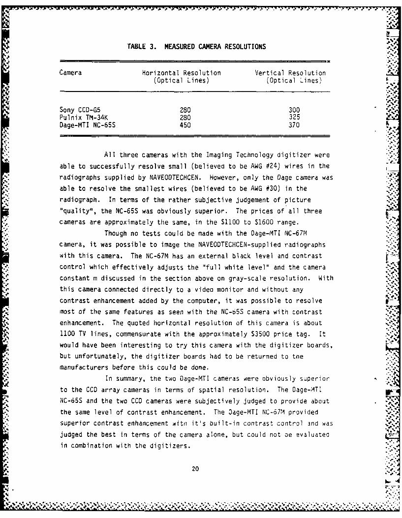
TABLE 3. MEASURED CAMERA RESOLUTIONS
Camera Horizontal Resolution Vertical Resolution(Optical Lines) (Optical Lines)
Sony CCD-G5 280 300 lePulnix TM-34K 280 325Dage-MTI NC-65S 450 370
All three cameras with the Imaging Technology digitizer were
able to successfully resolve small (believed to be AWG #24) wires in the
radiographs supplied by NAVEOOTECHCEN. However, only the Dage camera was
able to resolve the smallest wires (believed to be AWG #30) in the
radiograph. In terms of the rather subjective judgement of picture"quality", the NC-65S was obviously superior. The prices of all three
cameras are approximately the same, in the $1100 to $1600 range.
Though no tests could be made with the Dage-MTI NC-67M
camera, it was possible to image the NAVEODTECHCEN-supplied radiographs
with this camera. The NC-67M has an external black level and contrast
control which effectively adjusts the "full white level" and the camera A
constant m discussed in the section above on gray-scale resolution. With
this camera connected directly to a video monitor and without any
contrast enhancement added by the computer, it was possible to resolve
most of the same features as seen with the NC-65S camera with contrast
enhancement. The quoted horizontal resolution of this camera is about
1100 TV lines, commensurate with the approximately $3500 price tag. It
would have been interesting to try this camera with the digitizer boards,
but unfortunately, the digitizer boards had to be returned to the
manufacturers before this could be done.
In summary, the two Dage-MTI cameras were obviously superior
to the CCD array cameras in terms of spatial resolution. The Dage-ilTI.
NC-65S and the two CCD cameras were subjectively judged to provide about
the same level of contrast enhancement. The Dage-MTI NC-67M provided -'
superior contrast enhancement witro it's built-in contrast control and -Nas
judged the best in terms of the camera alone, but could not be evaluatea
in combination with the digitizers.
20
',-
[ - ; +.- -,
Logarithmic Amplification of the Video Signal
Film radiography is an inherently logarithmic process, where
film density is proportional to the logarithm of X-ray exposure (equal to
the product of the intensity and duration of the X-ray beam). If two
objects are radiographed with two different exposures, the film densities
of the two objects will be different for the two exposures, but the
difference in film densities for the two objects will be the same in both
exposures. The analog signal from a video camera is proportional to . .
light intensity, and the difference in the analog video signal for the
two objects will not be the same for the two different expobures, thoughtheir ratio will be. Thus, the same objects, radiographed twice with
different exposures, may appear drastically different when viewed with alinear camera.
For this reason, the sensitivity of the digitizer to changes
in film density is greater for small film densities than it is for high
densities, as discussed above. A difference in film density which is
visible at one density range may not be at another. A solution to this
problem is to logarithmically amplify the video signal from the cameraprior to the video digitizer. The sensitivity to density differences
would then be uniform across the entire density range and small density
differences would be as apparent at high film densities as at low
densities.
The Light Table
The most effective means of illuminating the radiographs is
with a light source on the opposite side of the film from the camera.The amount of light necessary will depend on the camera and the lens
used. In the experiments conducted in this programn, the radiographs qere
* illuminated with 180 foot-lamberts. This light level was more than
adequate for all of the cameras evaluated in this programn.
21
4 -
e2' r- r z
Video cameras display an entire image in 1/30 of a second.
Fluorescent lights have the disconcerting habit of turning completely off '4
every 1/120 of a second, or four times for every image. Video cameras
are fast enough to catch this and vertical bars can sometimes be seen in
the image, especially during contrast enhancement. Incandescent bulbs r.4
are less bothersome in this respect, but still have a noticeable
flicker. Please note that a difference in film density of 0.01 corre-
sponds io a difference in light transmission of only 2.3 percent. To
.4, reduce the noise in the digitized image, the flicker should be less than
this. Thus, it is recommended that incandescent light bulbs powered by a
DC source be used to illuminate the radiograph.
This does mean, however, that the illumination-across the
light table should vary hy less than this amount. Illumination varia-
tions have a relatively luw spatial frequency, which the human eye is
very good a filtering out. On the other hand, portions of the radiograph .f -
will be unviewable during contrast enhancement if the light level varies
by too large an amount. It is recommended that the variation in illumin-
ation across the radiograph be no greater than 10 percent.
Recommended Equipment
The following equipment is recommended for System I.
1. Compaq Plus portable computer with integral monitor, 360
kB floppy disk, 10 M8 hard disk, and 640 kB system RAM.
2. Imaging Technology digitizer board.
3. Oage-MTI- NC-65S video camera.
4. Software to be provided by a third-party vendor.
.4"
System I Cost
The cost of the portable computer, including RAM add-on card,
is approximately $4600. The Imaging Technology digitizer is approxi-
mately $3500. The Dage-MTI 65 series cameras cost between $1300 and
22 '-"
U -m __ ' - ; - , . 3 . . i ..- J.' . . ... ] .c .-
$2000, depending on the exact configuration; the one evaluated (NC-65S)
in this program was about $1600. The total price, excluding software and
the light table, will be between $9400 and $10,100. It is estimated that
the software (amortized over 100 systems) and the light table together
will cost under $1000. Thus, the total system price shoula be between
$10,000 and $11,000.
Notes on Packaging
The envisioned System I will be contained in two portable
containers which can be transported to the working site a-carry-on
luggage on commercial airliners. In order to do this, the size of the
containers must fall within certain guidelines. These are that the sum
of the length, depth and width of the container must be less. than 45
inches (1.14 m). Nominal dimensions would be 21 inches (53.3 cm) x 16inches (40.6 cm) x 8 inches (20.3 cm). The Compaq portable computer is
already packaged to meet this criterion. One option for the second
container is to buy a case similar to the Compaq's and modify it to
contain the light table, camera, and camera lens.
CV.
.23
°• "
m ,
. . . . . . .. . % • . .4*
-J• " - " - " . . . # """""""' """""" ," , •••" d°. ',",' ',° % ,% . % '"% " , . " . ,
,*" '_,.' .-.-_'Z',Z.". ".".".-" ,".-" -",".".",",",'',."", ,'' ',w ," . . ," ', ," ,, -' ,". " ,"-,'',w',, , 'w %" .' ,'-"-"' : ",' ,'" - .
DESIGN OF SYSTEM II
System II is mobile radiographic system containingsophisticated radiographic equipment, films, film developer and image
% processing/enhancement equipment. Unlike System I, System II is not
designed to be readily portable. Instead, System II is housed in an
air-transportable pod which can be loaded on military or commercial air
transport and flown to the nearest landing field to the site. Once on
the ground, System II will be loaded on a truck and moved onsite. -
Envisioned applications of System II are activities like screening
packages entering Olympic Village at the 1984 Summer Olympics or
rendering safe very complicated IED's where the allowable response time
can be measured in days instead of hours. An example of the. latter would
be the IED at State Line, Nevada.
Because cost is a critical issue in the decision to pursue the *"i
development of System II, two versions were actually designed. Both
versions contain exactly the same radiographic equipment, films, devel-
oper, and so on; the primary difference is the image processor and 5digitizer. System Ila includes the complete System I as the
processor/digitizer, while System lib uses a far more sophisticated, and
expensive, image processor and digitizer. It is believed that most of
the problems faced by EOD teams can be solved by the use of improvedradiographic equipment with only relatively simple image processing
requirements. Thus, it is the author's belief that System Ila is
the system of choice for EOD teams. Should it turn out that the more
sophisticated image processing capabilities are required, they can be
easily added later since System Ila is a subset of System Ilb. The only
extra considerations in upgrading from System Ila to Ilb is packaging the
equipment in the same (or perhaps an additional) air-transportable pod. ,. ,
The design philosophy behind System II is to give the EOD teams
needed flexibility so that good radiographs can be obtained under adverse
conditions. For example, the selected X-ray unit can generate X-rays
with energies ranging from 32 kV to 320 kV. The lower energies are
useful for radiograpning objects with low densities (plastics, wood, etc-24 .
24 .;
• ".V .\-: $ W . . -- .
<.-7 4L
while the higher energies can be used to penetrate over an inch of
steel. A variety of X-ray films were selected which have a much higher
density range than the Polaroid film used with the flash X-ray unit. The
higher density range of these films makes them more forgiving to L
overexposure without seriously degrading image quality. Since the
development of X-ray films is somewhat tedious, an automatic film
developer was also included. An image intensifier, which puts out a
real-time video image suitable as input to the image processing
equipment, was included so that the team can view the IED's at different
X-ray energy levels without having to go through the process of
developing films. And so on.
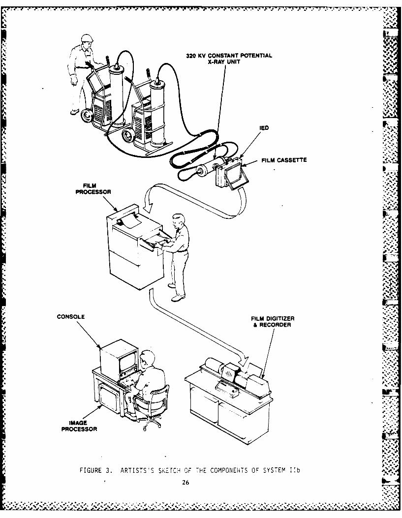
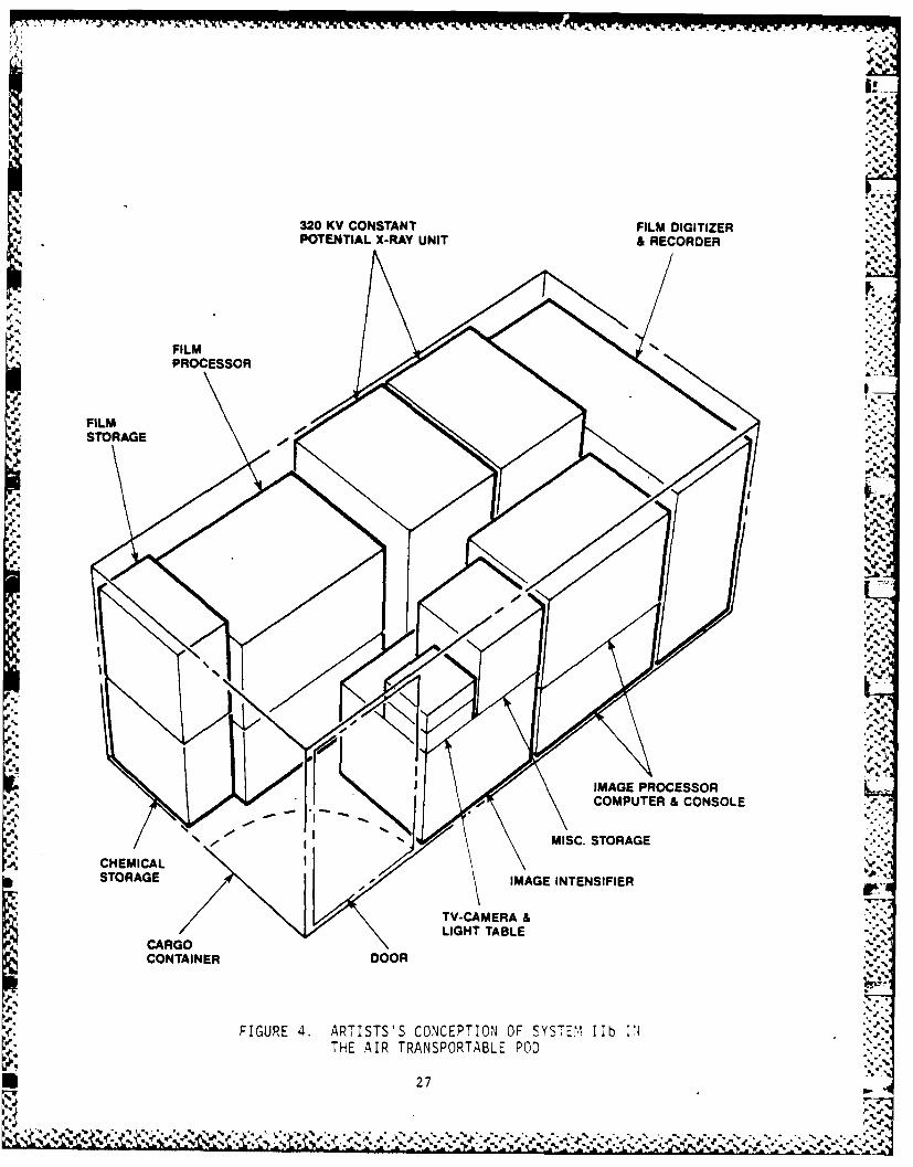
An artist's sketch of the components of System lIb is shown in
Figure 3, while Figure 4 shows an artist's conception of the system in
the pod. The X-ray unit would be removed through a side door to give the
operator a place to sit in front of the image processing unit. System
Ila would look similarly, except that System I would replace the
digitizer and image processing units shown in Figure 4. .
Functional specifications for System Ila follow, with
additional specifications for System hIb afterwards. The remainder of
this section discusses the selected equipment and the expected costs of
both versions.
One note is in order. Because of the complexity, size, and
cost of the equipment involved in System II, this was necessarily a"paper" design. That is, the selected equipment was not actually
evaluated as was done for much of the equipment in System I.
System-Ha Functional Specifications
Purpose: The primary purpose of Radiographic Enhancement System 11a is
to provide a flexible and powerful radiographic systen for use
by EOD teams.
1. System lla shall consist of a hot filament X-ray unit,
various radiographic films, a film developer, an image
intensifier, and the System I image enhancement system.
25
.5" .2 .*-
W.' I. - ; , - -- .
320 KY CONSTANT POTENTIAL
X-RAY UNI
%4%
I..
PROCESSOR
CONSOLE FILM DIGITIZER& RECORDER
IMAGE t
PROCESSOR
FIGURE 3. ARTISTS'S SKETCH OF THE COMPONENTS OF SYS7EM Mb%%
26
IW-Irf L- 0 ..
32OKV CONSTANT FILM DIGITIZERPOTENTIAL X-RAY UNIT & RECORDER
p'L
FILMPROCESSOR
FILM
46.1
M STRG
STORAGEIMAGE PNESIIROCSO
COMPUTERA & OSL
4%eJ
*°5%
32KCONTAINER DOOR
FIGURE 4. ARTISTS'S CONCEPTION OF SYSEM Ilb :NTHE AIR TRANSPORTABLE POD
27 S
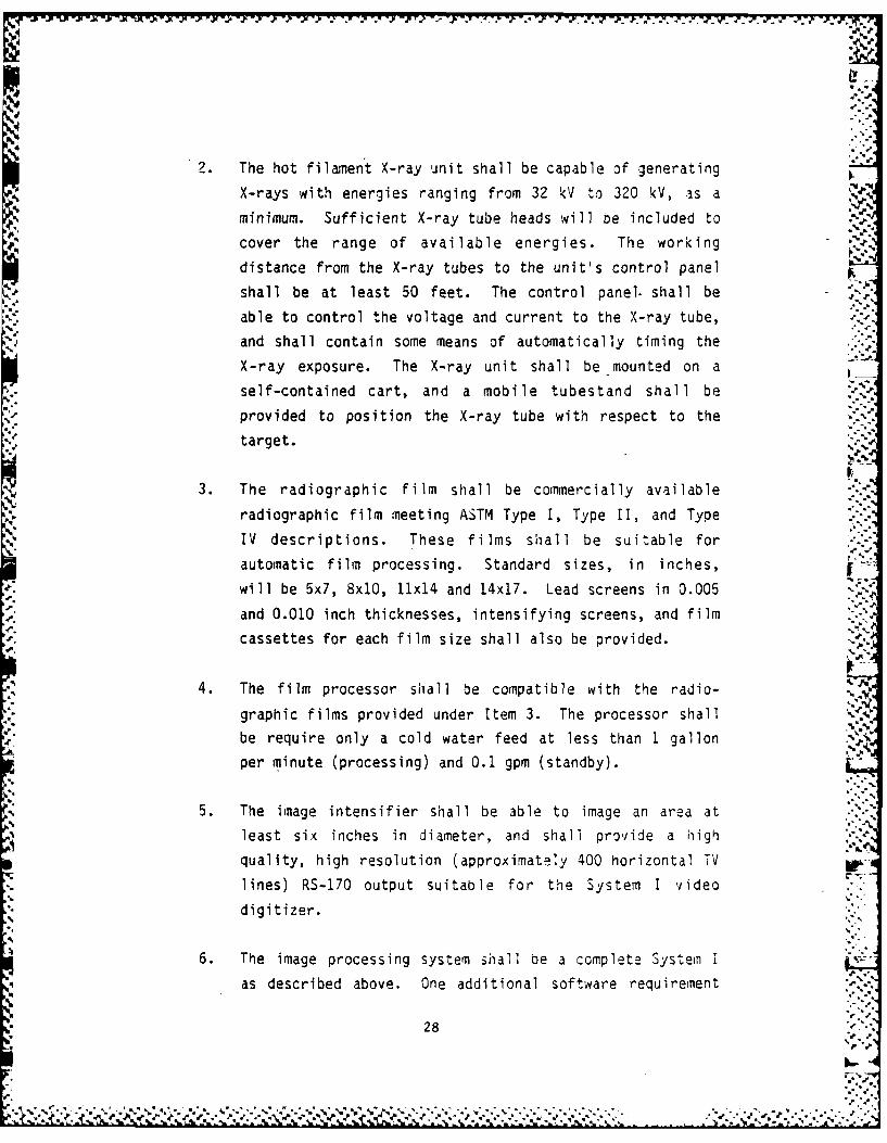
2. The hot filament X-ray unit shall be capable of generating
X-rays with energies ranging from 32 kV to 320 kV, as a
minimum. Sufficient X-ray tube heads will be included to
cover the range of available energies. The working
distance from the X-ray tubes to the unit's control panel
shall be at least 50 feet. The control panel. shall be .
able to control the voltage and current to the X-ray tube,and shall contain some means of automatically timing the
X-ray exposure. The X-ray unit shall be mounted on a
self-contained cart, and a mobile tubestand shall be
provided to position the X-ray tube with respect to the
target.
3. The radiographic film shall be commercially availableradiographic film meeting ASTM Type 1, Type II and Type
IV descriptions. These films shall be suitable for
automatic film processing. Standard sizes, in inches,
will be 5x7, 8x10, 11x14 and 14x17. Lead screens in 0.005
and 0.010 inch thicknesses, intensifying screens, and film
cassettes for each film size shall also be provided.
4. The film processor shall be compatible with the radio-
graphic films provided under Item 3. The processor shall
be require only a cold water feed at less than 1 gallon
per minute (processing) and 0.1 gpm (standby).
5. The image intensifier shall be able to image an area at
least six inches in diameter, and shall provide a high
quality, high resolution (approximately 400 horizontal TV
lines) RS-170 output suitable for the System I video
digitizer.
6. The image processing system shall be a complete System I
as described above. One additional software requirement
-"28
I..
is that the system must be able to store two images from
the image intensifier (made using different energy X-rays)
in memory and perform subtractive radiography as described
in our previous report. '
7. System II shall be housed in an ait-transportable pod
suitable for shipment on both commercial and military
aircraft.
Additional Specifications for System lIb
8. The advanced image processing/enhancement system shall be
comprised of a high resolution digitizer, digital proces-
sor to perform image enhancement, and a high resolution
output device capable of making a hard-copy of the
enhanced image.
9. The image digitizer shall be capable of digitizing at -
least a 10 x 10 inch film with densities ranging from 0.0
to 3.0 with at least 256 gr-ay levels. The maximum spatial
resolution of the digitizer shall be 1000 points per inch,
the minimum requirement is 100 points per inch.
10. The. image processor shall be capable of accepting imagesfrom either the high-resolution digitizer or from a
standard RS-170 video signal. The processor shall be
capable of performing all of the standard functions of
System I. In addition, the processor shall
a. perform subtractive radiography of images from either
the high-resolition digitizer or the image
intensifier A,.,
b. perform image restoration and deblurring algorit.imsC. be capable of accepting images digitized and stored
on System I.
29
aJ 4, ..
. . . . .. .. .... . . . . . . . . . . . L 'I [( t I tqd( t i _( r_#. . 1 "i" 1 . P# ° _"
11. The image output recorder shall be capable of recording
images generated by the image processor with gray levels
and spatial resolutions equivalent to the high-resolution
digitizer. If the recording medium is film, then the film
must be compatible with the film processor described in
Item 4.
12. The image digitizer, processor, and recorder must be
housed in either the same or a similar air-transportable ..'.p
pod as the rest of System II. At the site, the pod must
.L open up to provide a comfortable working area for the E0D
teams.
Systemn II Hardware
System II contains a hot-filament X-ray unit, a variety of
radiographic films, a film developer, image intensifier, and an image
processing unit. Specific equipment selections for these components are I
described below. In several cases, only one source for the equipment is -
indicated; comparable units from other manufacturers would suffice.
X-Ray Unit
To give added flexibility to the EOD teams, System II includes
a conventional hot-filament X-ray unit which can generate X-rays with
energies ranging from approximatel] 30 kV to over 300 kV. This range
will allow high quality radiographs of a variety of targets.
The contrast available in a radiograph depends strongly on the
X-ray energy used. Low density objects, such as woods, plastics,
etc. are best radiographed with low energy X-rays (30 to 100 kV), while gawkthick sections of dense materials such as steel require X-rays with high
penetrating power (100 to 300 kV). All of these objects can be radio-
graphed with a single, variable energy unit, though not necessarily at
the same time.
30
To generate the high voltages necessary to drive the X-ray
tubes, an alternating current is sent to a high voltage transformer,
which generates the necessary voltage. This voltage is rectified and
sent to the tube. If the voltage is unfiltered, then the voltage across
the tube varies from some maximum value to zero; the net result is thatX-rays of all energies are generated. In general, this will produce aninferior radiograph. Newer, constant-potential units filter the voltage
applied to the tube, with the result that the X-rays generated have a
more uniform characteristic. Typically, useful X-ray production is 30
percent higher with a constant potential system as compared with an
unfiltered system. The increased production allows the c'urrent to the
tube to be reduced with a concomitant reduction in the focal spot size.
The result is i far superior radiograph.H A good constant-potential X-ray unit is the Philips14 MG 321L ,.
. 320 kV X-ray system. The unit is housed on two carts which are moved tothe site and then connected with a cable. Contained on the carts are the
controller, high voltage generators, and integral oil cooling system for
the X-ray tube. The tube (MCN 322) is capable of generating X-rays in
the range of 30 to 320 kV, and can be used to expose up to 3 inches of
steel with exposure times of about 15 minutes. The tube has a dual focal
spot size of 1.3 mm and 0.3 mm (at reduced current levels). The tube can
be situated up to 65 feet from the control unit. The MG 321L can also
use a MCN 166 X-ray tube, which gives a finer focus (down to 0.4 mm),
.. with X-ray energy up to 160 kV.
The cost of the MG 321L is approximately $60,000.
Radiographic Films
Good quality radiographic films allow significant leeway in
exposure while still producing high-quality radiographs. This is
primarily because radiographic films have usable density ranges ranging
from about 0.5 to well over 6. There are many suppliers of films; the
14 E. I. duPont de Nemours & Co. (Inc.). Photo Products Deoartment. V-
Wilminqton, DE 19898
31
-S.... . . . ... -. Z.
".'.': .','..'.'.: ';,=.'.'" ".''.".¢'';'.-,",.". "...," , " , .. . . . . . . . . .. . . . . . . . . . . . ... ."... . .... . . . . . . .".-"".. . . .".. . ... "
most often used in this country are Kodak and DuPont. It is suggested
that one of these two sources be used since the film is readily available
-n any part of the country. DuPont films will be used as an example. .,W%-,
DuPont makes seven different radiographic films with varying
degrees of contrast, graininess, and speed. These films are denoted NDT
35, 45, 55, 65, 70, 75, and 91. The first four are low speed, very high
contrast with very low graininess. The next two are medium speed, high
contrast with low graininess, and the last is very high speed with high
contrast and graininess. The films come in a variety of sizes; the most
useful will probably be 5x7, 8x10, 11x14 and 14x17. System II should
have a complete selection of each type and size. DuPont films are well
suited to automatic processors.
Because each film type has a different speed (sensitivity to
X-rays) a common technique used to radiograph an object with widely - -
varying densities is to place two or more films inside one film pack.
Thus, the thinner or less dense sections are viewed on the slower film,
while the thicker or denser sections are viewed on the faster films.DuPont, as do other manufacturers, can also supply a wide range As
of lead and fluorescent screens, and film cassettes. These items should
also be obtained for System II. The total cost for films, cassettes, and
screens will be in the neighborhood of $7000.
Film Processor
Developing radiographic film is not exceptionally difficult,
though it does require a dark room with chemicals maintained at carefully
controlled temperatures. This necessity can be avoided by using a film
processor which automatically develops the film without the need for a
darkroom. The better processors require only cold water and electricity,
along with the appropriate chemicals. Water requirements are typically
less than 1 gallon per minute.
Development times vary depending on the type of film, but a
fully developed and dried film can usually be produced in less than 15
Sde
32
S%
°" J"
.d-'
minutes. Two representative processors are the OuPont ' Cronex NDT 100
and the Alphatek 16 AX-700. Both processors are available for less than
$10,000, including chemicals. .J
Image Intensifier
Image intensifiers represent a different imaging source for
radiographic procedures. The advantages of intensifiers are real-time
imaging and an output which is RS-170 compatible and can be input to the
image processor directly without going through the film development and
digitization. Disadvantages are their relatively large size, precluding
their placement behind all objects, relatively small viewing area (up to
about 10 inches in diameter), and higher graininess in the image as
compared to film. Thus, intensifiers are not a replacement for film
radiography, only an adjunct.
Several uses we can see for the intensifier are examining
packages very quickly, viewing an object with X-rays of varying intensity
and energy, and providing the images for the subtractive radiography.
Image intensifiers are supplied by a variety of companies, including
DuPont and Ridge 16.
4 Additional Equipment for System lIb
As we discussed above, the difference between Systems [!a and
lIb are the image digitizer and image processor. System Mla uses the
equipment detailed under System I as the digitizer/processor. System MIb
has, in addition to System I, a high resolution digitizer and recorder
and a high-speed image processor. These are detailed below.
t'. ~.." . -,
15 Alphatek Corporation, 650 W. Lake Street, Chicago, IL 60606
16 see 13 above.
.33
-. ...
. . . . ....'- " m ' - . " " " ".. S . "' *. ".. . . .- ". .".. . ."."". ."". "" "" ".. . . ." -" " "" ° " *" " " , ," """"""k , "". "" """
p o' %%
Image Digitizer and Recorders
The main drawback of the image digitizer in System I is the
relatively low spatial resolution, nominally 512 pixels in each direc- ...
tion. If an entire 8 x 10 inch radiograph is digitized with this system,
the pixel resolution is about 0.02 inches. We believe that, for some
applications, spatial resolutions of 0.005 to 0.010 inches may be
required. With System I, this can be obtained only by decreasing the
field of view to about one-fourth to one-half of the radiograph at any
one time.
One other drawback of System I is that there is no way to make
a permanent hard-copy of the enhanced image. Thus, to work on the IED
(to place shaped charges, for example), the image processing system or a
separate video monitor must be carried near to the IED. . _"
Both of these drawbacks can be solved by including a high-
resolution film digitizer/recorder with System lib. The only available
device with this capability is the Optronics17 P-1700 Photomation Scanner
(digitizer) and Recorder. This model can digitize up to 10 inch x 10
inch film images with variable spatial resolutions ranging from 25
microns (0.001 inches) to 400 microns (0.016 inches) in steps which
differ by a factor of two. At the highest resolution available, an 8 x
10 inch radiograph would give about 80 million pixels, far more than most
computers can handle at any one time. With resolutions which are more
useful for this application (100 or 200 microns), the same radiograph
will give us between one and five million pixels. Though these are still
large numbers, they can be handled by most of the newer microprocessors.
The gray-scale resolution of the digitizer is one part in 256. -
However, this can be selected to be either a linear scale (like the video
cameras) or a logarithmic scale. The advantage of the latter scale is
that the density resolution of the digitizer is constant and does not
drop off at the lower density ranges as it does with the linear scale. -!.
For the logarithmic scale, the density resolution can vary from 0.004 to
0.011, in three steps. In the linear mode, each step in gray-scale
17 Optronics International Inc., 7 Stuart Roa% Chelmsford, MA, 01324
34
- .- - -- - - - - - . ...- :q
44
"
corresponds to a difference in light transmission of 0.39 percent, with
a minimum value of 0.25 percent and a maxi-um of 100 percent. The
density resolution in the linear mode ranges from 0.41 at the low end of
the gray-scale to 0.002 at the high end.
The Optronics digitizer is not a real time device, since the
maximum data taking rate is 32000 points per second. If the resolution
is 100 microns, an 8 x 10 radiograph can be digitized in something less AZ
than 3 minutes. Though slow, this time is judged to be reasonable.
The film recorder side of the P-1700 is very similar to the
" digitizing side. The resolutions (both spatial and gray-scale) as well
as the data rates are exactly the same; the only difference is that
instead of measuring the light transmitted through the film, the film is
exposed with varying amounts of light. This film will then be developed-1 with the film processor included with System II to give a one-to-one copy
of the enhanced image which can be used by the EOD teams while rendering": the IED safe.
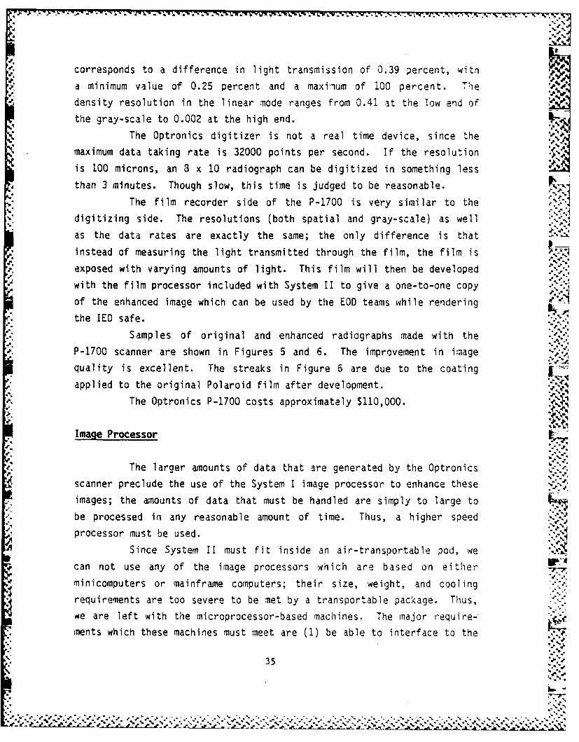
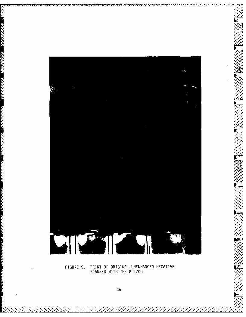
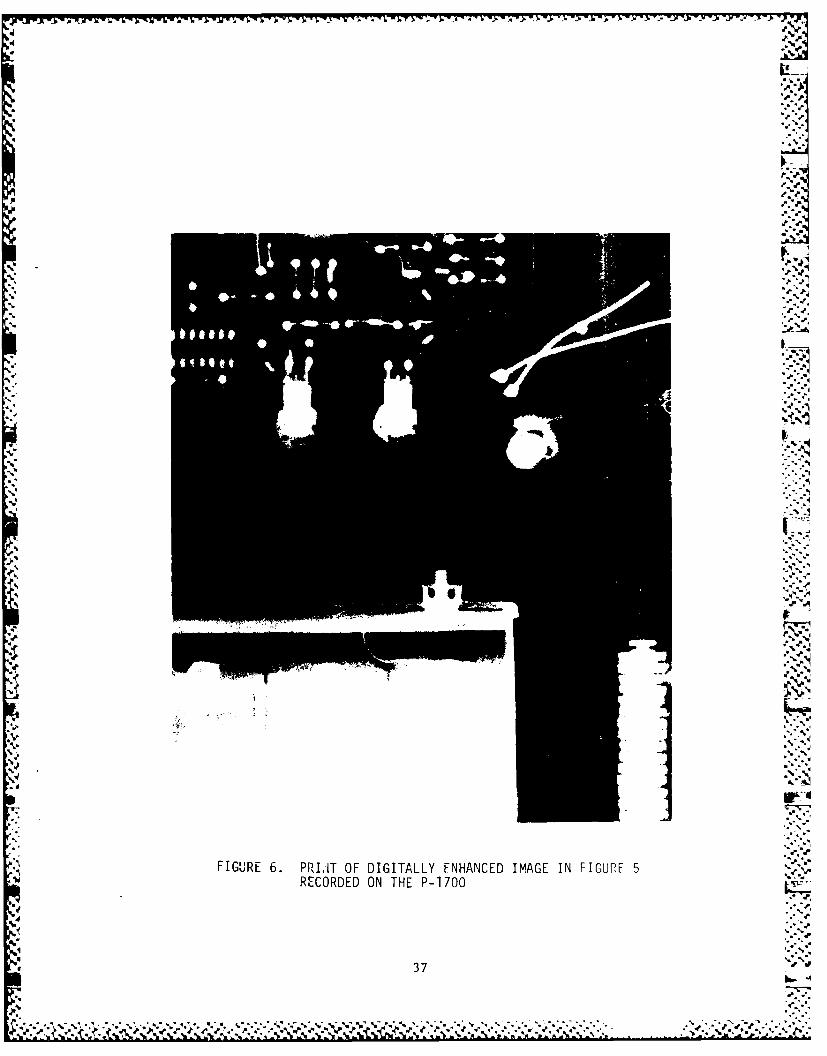
Samples of original and enhanced radiographs made with the
P-1700 scanner are shown in Figures 5 and 6. The improvement in image
quality is excellent. The streaks in Figure 6 are due to the coating
applied to the original Polaroid film after development.
The Optronics P-1700 costs approximately $110,000.
Image Processor
The larger amounts of data that are generated by the Optronics
scanner preclude the use of the System I image processor to enhance these
images; the amounts of data that must be handled are simply to large to
.°* be processed in any reasonable amount of time. Thus, a higher speed ."..4
processor must be used.
Since System II must fit inside an air-transportable pod, we
can not use any of the image processors which are based on either
minicomputers or mainframe computers; their size, weight, and cooling .
requirements are too severe to be met by a transportable package. Thus,we are left with the microprocessor-based machines. The major require-
ments which these machines must meet are (1) be able to interface to the
35.* :',
a.. a. ~ ~ - a * ~ ~ *' % ~ .% V ' 4, % . .a ~ .. . . .** ** 4* a -* . *** ** **-* *
e, %,
'.p
b. -
a 1. a A -, - - - - - - - -.
0 *.. ...~I
P.
j
~A,.. . I
-4* -
J
*'0
N
I
.4.4
**,~'* a*,q
.4
______ RW~
- - --- ~ *
'U
-.* *00FIGURE 6. PRIJT OF DIGITALLY ENHANCED IMAGE IN FIGURE 5RECORDED ON THE P-1700
q
* 37
JO.. ~ ~ ~:K.s~ V~? a '~2~V.-4C~~ > ~'~q~;K-~j 'U ~U
Optronics scanner, (2) be able to handle several megabytes of image -.
memory, (3) perform computations quickly, and (4) use a well-known system
bus for which other peripheral equipment is available.
There are three major families of microprocessors which might
meet these requirements; these are the Intel18 80286, the DEC1 9 MicroVAX
II, and the Motorola 20 68000.
The Intel 80286 is the big brother of the Intel 3088, the
microprocessor used in System I. The major differences between the 80286
and the 8088 are larger instruction set, higher speed, and increased
memory handling requirements. Because the instruction set of the 8088 is
a subset of the 80286, a programmer familiar with the 8088 can easily
learn the additional instructions of the 80286. In fact, many compilersthat run on the computer used in System I can be used to generate
programs for the 80286, a strong advantage. The 80286 can support up to
16 Mbytes of memory, sufficient to hold somewhere between 3 and 12 images
generated by the Optronics scanner. The 80286 is available on the
Multibus, which is well supported by add-on peripherals.
The DEC MicroVAX II is a new microprocessor which is nearly V.functionally equivalent to the DEC VAX line of minicomputers. The
MicroVAX can address up to 9 Mbytes of memory, the equivalent of I to 6images. With an added numerical processor, the MicroVAX can in most
.. situations perform computations at speeds 80 to 90 percent of the VAX
11/780. The MicroVAX will run most of the software written for the VAX;
there is probably more software written for the VAX than any other
minicomputer, so that the MicroVAX, unlike other microprocessors, started
out with an extremely large software base. The MicroVAX is available on
the DEC Q-bus, also supported by an extremely large number of add-on
peripherals.
The Motorola 68000 is one of the most popular 32-bit micropro-
cessors on the market today. Like the intel chip, it can support up to
18 Intel Corporation, 3065 Bowers Ave., Santa Clara, CA 95051
19 Digital Equipment Corporation, 2 Iron Way, Marlboro, MA 01752
20 Motorola Semiconductor Products Inc., 3501 Ed Bluestein Blvd., Austin
TX 78721
38
•.~ ~~~~~ ~ ~~ %, Pr " m , ,.4 * # ", * . ". *, -° - , *. -. ". o -. m ° - - --# . . .
16 Mbytes of memory, and with an added numerical processors can reach
speeds comparable to the MicroVAX. Though relatively new, the 68000 is
available on several buses, including Multibus and the VME bus. Both are
well supported by vendors of add-on peripherals. Because the 68000 is
relatively newer, its software base is not as large as for the MicroVAX.
The selection of an image processor based on one of these
microprocessors can not be made on the basis of cost; a system built
around any one of them will cost between $50,000 and $75,000 depending on
the exact configuration. In terms of speed, the MicroVAX and the 68000
are roughly equivalent and better than the 80286. The MicroVAX has a
much larger software base than does either of the two, and in fact, imageprocessing software is available for the VAX already. Since with any
computer system, the cost of software development far outweighs the cost
of the system itself, and since DEC has service groups scattered through-
out the country that can provide overnight service for most hardware
problems, our first choice would be the DEC MicroVAX II and our second
the Motorola 68000.Hardware Requirements for System HIb. Besides the processor,
memory, and mass storage (hard disks and magnetic tape), the image
processor should contain a video digitizer and a high resolution videomonitor capable of displaying at least 1024 by 760 images with 256 graylevels. Imaging Technology is one example of a company that can supply
both of these products.Software Requirements for System lib. In addition to all of
the functions provided by System I, System lib should provide the "
following functions:
(1) Accept images digitized by the Optronics scanner.
(2) Send enhanced images to the Optronics recorder.(3) Accept digitized images stored on the System I processor
for subsequent processing.
(4) Digitize images from either the video camera or image
intensifier.(5) Perform subtractive radiography as described in our last
report.
39
_ % -.% -,
*~ %* ~ * *55 *,,. %
'6) Perform deblurring to remove blur in radiographs caused by
the finite focal spot size of the X-ray beam or by large
object-to-film distances.
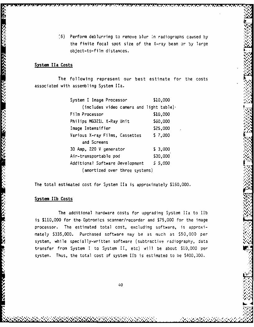
System Ha Costs
The following represent our best estimate for the costs
associated with assembling System Ila.
System I Image Processor $10,000
(includes video camera and light table)-
Film Processor $10,000
Philips MG321L X-Ray Unit $60,000Image Intensifier $25,000
Various X-ray Films, Cassettes $ 7,000
and Screens
30 Amp, 220 V generator $ 3,000
Air-transportable pod $30,000
Additional Software Development $ 5,000 -
(amortized over three systems)
The total estimated cost for System Ila is approximately $150,000. ,
System 1Ib Costs
The additional hardware costs for upgrading System Ila to lib
is $110,000 for the- Optronics scanner/recorder and $75,000 for the image
processor. The estimated total cost, excluding software, is approxi-
mately $335,000. Purchased software may be as much as $50,000 per
system, while specially-written software (subtractive radiography, data
transfer from System I to System I, etc) will be about $10,000 per
system. Thus, the total cost of system Hib is estimated to be S400,000.
40
CONCLUSIONS AND RECOMMENDATIONS
The design of two radiographic enhancement systems for EOD
. teams are discussed in this report. The first, System I, is an image
enhancement system that can increase the contrast and clarity of radio-
graphs made using the existing EOD X-ray system. System II offers
improved radiographic capability through the use of a conventional
hot-filament X-ray unit and radiographic films as well as an improved ..-
image processor.
Both systems will significantly increase the radiographic
%' capabilities of EOD teams. System I, designed to be transportable as
,; carry-on luggage on commercial airliners, will be carried by EOD teams *.,-.
along with existing EOD radiographic equipment in a rapid. deployment
mode. System II, because of its larger size and weight, is housed in an
air-tranportable pod for situations that require radiographic capabili-
ties beyond those of System I. As many as 300 copies of System I may be
required to equip all EOD teams, while only three copies of System II,
located at strategic positions in the United States, will be necessary.
The expected cost of System I is approximately $10,000, while the
expected cost of System II will range from $150,000 to $400,000, depend-
ing on the exact configuration selected. The lower cost is for System
Ha, which uses the image processing capability of System I, while the
higher cost is for System lIb, which includes an image processing system
with much greater capability.
The fabrication of both Systems I and II are technically
accomplishable witIT primarily off-the-shelf equipment. Items which
cannot be purchased directly are the light table for System I, the
air-transportable pod for System II, and all or portions of the software
for both systems.
Our recommended course for the development of these systems is .
as follows. First, a prototype of System I should be built and tested
under actual field conditions. Once this is completed, and assuming that
the outcome is as positive as we believe it will be, then full-scaleprocurement of System I can begin. The next logical step would then be
'5 41
41 ..
* . F * F" .* -
L
to build and evaluate a prototype of System IIa, since it is a logical
extension of System I. The development of System lib, a superset of
System IIa, would then follow should it be deemed necessary.
In the course of building the prototype of System 1, we also
recommend that development of a logarithmic amplifier for preprocessing
the analog signal from the video camera be undertaken. This step should
significantly improve the ability of System I to enhance poor contrast -e
radiographs.
.42
%.
%-. f -',4
I#.-%
.4
I°4*4- %"
,-."%"
" '{ " W' %'' ' " ' °
" " '" '% ' ' '' °'% " ' "'' '" % " " "° " " " ' ' "' " "" "" "" "" -" " " ". ". • "-. "
€., ,W, " , ' ", - ,- . . -," w " -, 1.W . '.'-,-w @ , @ W , " ","- 42 " - - '', -"-4,-
I'.#'
i*. .%.-
,I '
APPENDIX A %
t;.
i I-a
a. , .-
p , " .,,..
APPENDIX A
r-% %-~ ,- s. .;.' r ,-,rw F ~ '.--W-w . - - r. . . . . . . . . . . . . .... . * ... °. . . . . -*
'_
.."
q'~w,,"t
p a~
:. - -N.
)__
r. -
hi2.
2
-C-2-' :
a.
Ths pae inetinllef lakI
''.-S -=', "
i
..-.*.
p. "_"* , - ,"""" ° ",/', t /' d ''.' '
'% ' d
"
" " "' " " " * " "" " '' "% '"" ° ." "
.. . ... . . . . . . . . . . . . l L'= ., . . e . ,.c . i i . _- .. a,_:
. :._L.
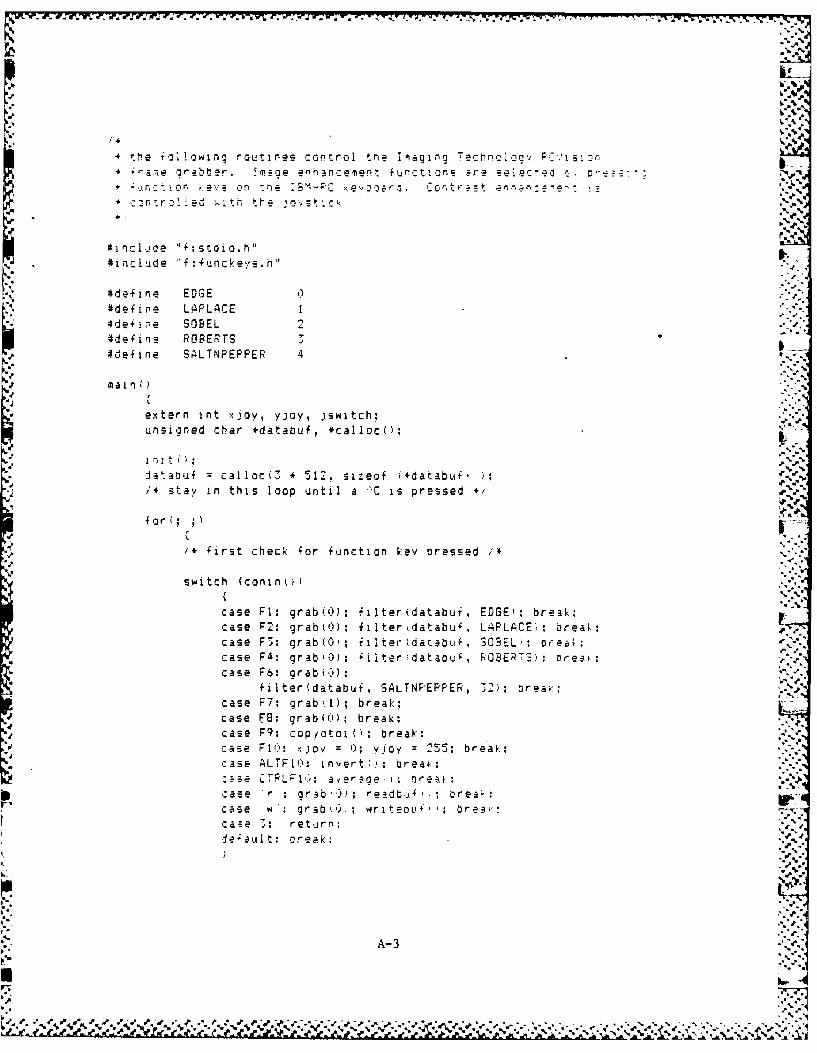
I'-
4 the .o, !:in, routines control tne Imaging - re n c o9v e_-, s_4 a .rabber. .zge enh.nce,ee t tuncti.ons Are se eced - -
,. -, r, .ev s ,.on tie . ; evo. 2r.n . -g , : Fn - S%
,:c:ntr.l 1ed with the o , t-c"
:ncl.de :stdio.hSIn lude nf:kunc k.es .h J.-
#define EDGE 04define LAPLACE "4define SOBEL#de~ine ROBERTS 3#define SALTNPEPPER 4
extern int xuov, yjoy, jswitch;
unsigned char *databuf, *calloc();
ja.abuf = calloc(7 * 512. si-eof (+darabu , j-/* stay in this loop until a .C is pressed
f o r '; ; .
/* first check for function key pressed /*
switch (conin.
case FI: grab(O); filter(databut, EDGE): break:case P2: grab()); filterkdatabuf, LAPLACE;: oreak;case F3: grab(O; filter(databuf, 30 E- ; breal:
case F4: grab 0): +ilter databui, ROSERTS): oreai-case Ft: arab();
filter(databuf, SALTNPEPPER, 32); breaK: ,
case F7: grab~l); break;case F8: grab((); break;caSe F9: copyotoi(i; break:case PO: ioy v 0; V joy 255: break;V case ALTL0: nvertfe; oreai: ;
tTL16; a er a ae o; -*ase r : grab") readbulf l orea' :case 'w : grab ,), writeOL, : brea.case 3: return:.ie'ault: oreak:
) .lop .-
A-°3
J ." P - "
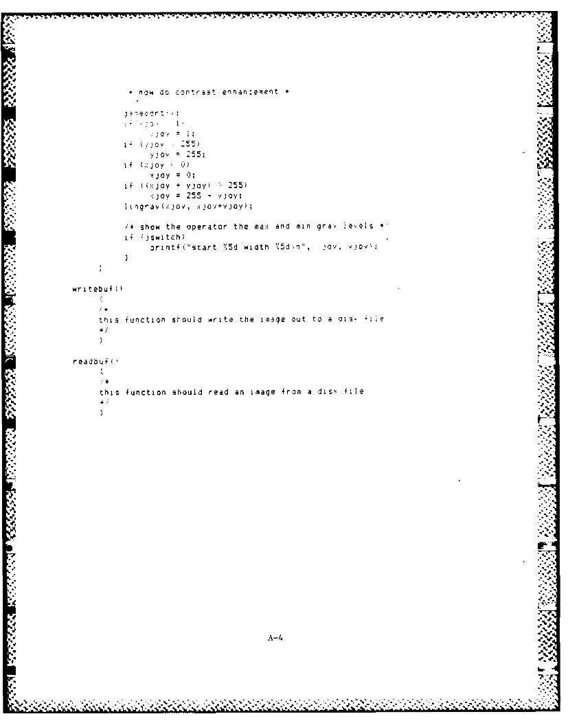
S.-.
iv J l..
jjoy
JJSc-5-
yjIo'.- =-25:.4% i
if (;'joy S+ c
' N joy = :
if k(xjoy + vjoy) 255),joy = 255 - Yjay"
I ingray(.xjov, xjov+vjoy);
"* show the operator the ma~: and min qray ie,,,els ,if ;jswtch)
printf k'start 75d width %5dxn", jovy, v iov:-
"* writebufi)
this function sOL!ld write the image out to a oii. 4, ie
.4 .. . '
readbuf .5"
this function should read an image from a disk file
A-
7.
A4 :- .
S " . .: .
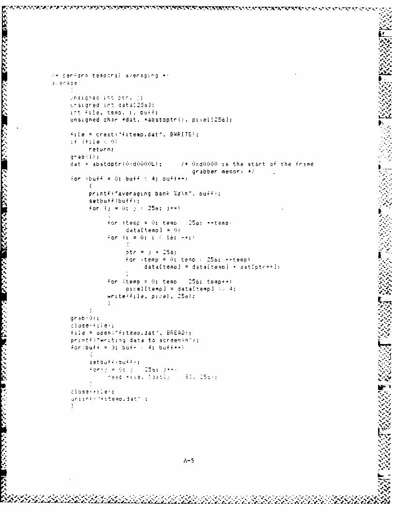
r.~~~~~S :51a- ed 1 1
a~~~~~~ 'S. e '. t .at I f
unsined hir dA-t *a stopr(,, pl~ei(:I6]1 r aUitmp d t BRIT
0~
return;
* : a nr Iir aer:
d a 3b topt (6!d()Co(')L /* (Jxd (*))() i s he tar of he ramgrabbe memor
unl~edchr (demp *abstepU opixei+ft em
ifr (f:Ie 1
dat aatopr (c d':'OL) I =*O dOO iso th ca 0,t of th+t
or 'u f or; buff - em Z5; bumpf+
prnfgeai' ban bdn" buf
setbuff (buff
fo (i 0:i1; r
+t T *6 P6~
4- ~ ~ ~ ~ ~ l for tem e;tjt eod3 ateo =teatio 4otor
4A-
fo (tmr ;tm 5:tm+;.
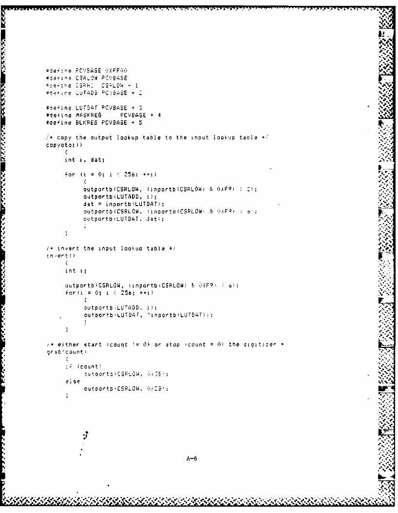
e- i -n A E f- X F 6 6
Ct1i C3R-.JW F'C'YE.,SE
+ -. E- UT 'DD r*C7ESE + %
#de~inz LUTDAT PCVBASE + 3#deiirne MASi:REG PCV!BSE + 4#deiine SLKREG PCVBASE + 5
'copy the output lookup table to tihe inout lookup table *
it i , dat;
for ii = 0.. i 256; ++1) -
4outportb(CSRLOW, (inportb(CSRLJW) & C)XF9) Z);
a dat =inportb(LUTDAT':,outportb(CSRLJW, iinportb(CSRLOW' & C'AF9)outporto'LUTDAT, dat;:,.-
1* inv'ert the input lookup table Zin ,ert (
int i;
outportblOSRLOW, IinportbkCSRLOW! & iC'XF9fo = 0; 1 %"256; ++1).~.
outportbl'.LUTADD, 1);outoortbiLUTDhr, 'irnportbtLUJTDiAT)):
Ieither start (count 0 O or stop 'count 0) the d~altizergrab~count;
c (oun t
out oor t rCERLOW, C, 2B'
A-6
d* re
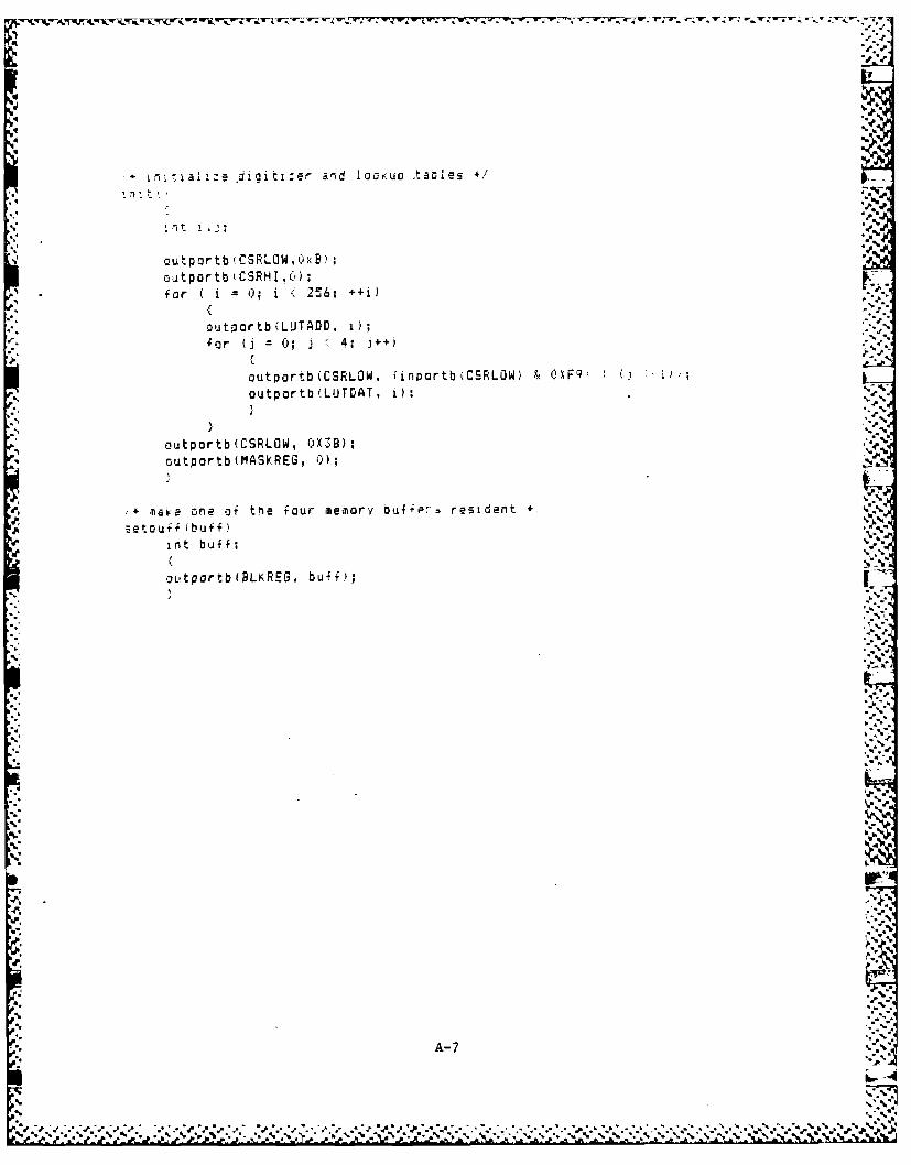
-4n rui al' e digi ti ,-r and IQrO a c,*1 01e
t 1%
outportb qCaPLOW.O'xBY.ouitportb'CSRHI.') ;
- for ( -i 25i ' 6; ++i)I
outportb(LUTADD, 1);
for (j = 0; j 4.-++
outportb(CSRLOW. iinportb(CSRLOW) & C'XF91 1''
outportb(LIJTDAT, 0;:
outportb (CSRLOW, 038);outportb(MAS!REG , 0).;
.,n*aka one of the four miemory/ uuftP- resident
setouiffbufint buff:
outportbfBLKREG, buff);
4A-
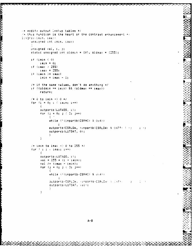
- , -- 7.A 'A-J4"PIYY-7Ur xWS TW3.71V w N-T M TVM- -M - 91 7-7
mdif', output looku o tables */this function isthe heart of the contrast e-hance *'
qnsl~~~ned int im n,.fl
unsigned val, i, j; =~,Od~ 25;'static unsigned int oldmin f, lm,
if limin<0,
if Urnax 2755)imax =255;
if imin >irnax)
imin imnax - I:
/+ if the samie values, don't co anvthina erif ((oldmin ==imin) && (aidmax imax))
return;
0* to imin ->0
for (i 0 i 'irmn; i++)
outportn(LUTADD, 0.:
for (i 0; j '3: j++)
mwhile ('(inportb(CSPHI) &~ Cyx4))
outportb(CSRLOW, (inportb(CSRLOW) . XF; :outportb(LUTDAT, 0);
;imin to imax-> 0 to 255 4
fo r : i irnax. I+.+)
outportb LUT~IDD, i);val =255 * (i - iPnval /:(imax -mn
for (j = 0, j j; +.)
whi le I' (irportb CSR H I o u4
SL t po :) E r V, :t oChm
A-8
AL .~u
oldminL imin oldmax im
* ~jr j = 1 -~%
do
whie 'UnprtbCSRI) A-9)
i n'- a~ s t} I* oy t ck il Dosition *',- - .. . .-. . . . . . . . .o
. 4..- q .- . . =- - 2 5 ! J, S t c k o c s t i c n * 1-- = * ~ 'r cr buttons *
* - .aeport Adedptor to control contrast enhanc,-emer,- *, q e e p u r t ; ;r
±org noest p, xy;
o r.-.'q
V.- = oyst'); /* assembly language routine tofind joystick position*/ .'
x (xy > 16) & Oxffff - 32:y =xy & Oxfff+f 321
jy += (x - 20) 4;else if (x : -20)
4'JOy += (x + 20) 4;if (, > )
I- 20)4: [else if , -20
y JDo + (y + 20) 4; '-,
-switch - inportb Ox201 & Ox3:.-
a?.V4.-!
..-.-
A-10"% P1*
'a,' "
'I_--/ ",, ,.," ,'" . " . " .[ .p . . . . , . ' ' " ". " ". . , ", % ," , ,i ,.,, , •.,.,
di ec cosa in u /o t u routines- - ~ .-
unsign d r-ha al.-h
stadirct consoeinu'otu ruins*
e- ss.d =ucXft
siqcnd nr &i ,ah:
i(regs al
static conin':
regs.dx 0,ff caregs.ah = 6;-
resiturn siintsl&reas,&eq)
IL,
A-11'
* ~ ~ l *ie *ler rQS ;,or the lrna';,n Techno! oav r %~-;rime grlboer
1~~~~~ nc 1 l T .C
abs ina croa reglocal absior reg ,regage abEIieg req
s : naopendm
neqadd macro parmiinov al , parmi
9assume that ah = o alreadysub b.,, axendm
ac c b m ac ro a araiov al parmllay ah.0add b , axendm
* screen memory and 1,10 locationsSCNM EM equ ')DOOOi
*SCNBNK equ OFFOOh+5
parameters on stackB UF QFC e qu @ab
EUFSES equ @ab+2 .
*FFUNC eau @ ab +4 -.
G P T equ @ab+6 %i
automatic variablesRECNT equ-S, 0 W equ -4
PFUNC e q u-:
row/column dat2 reierence in terow b.i4er
DCC e 13U
v D1 equ 514
A- 12 S
JvS
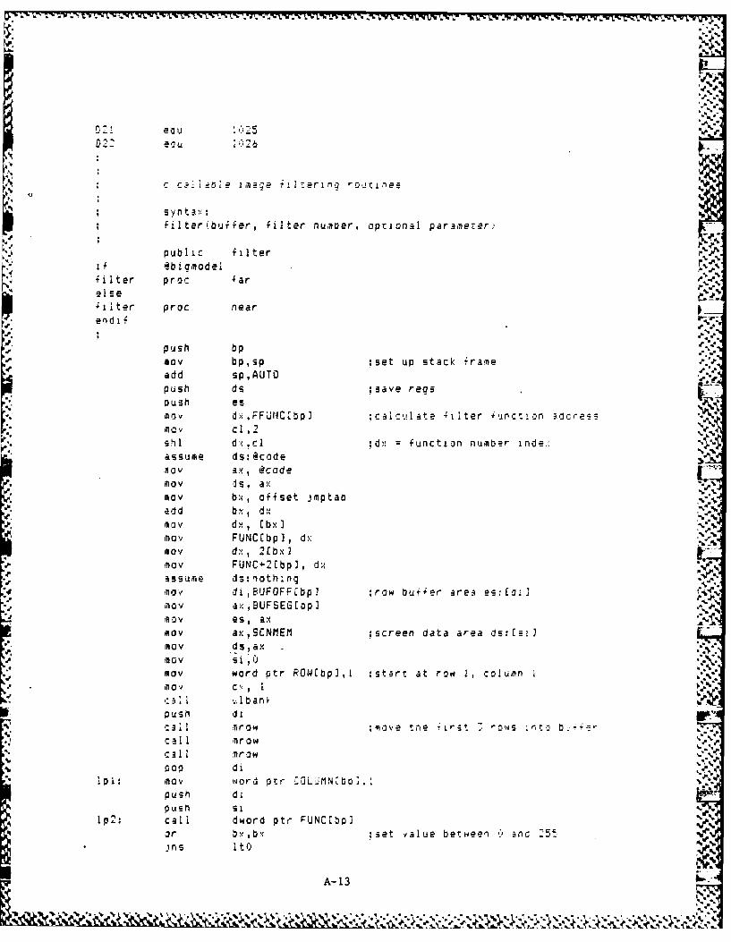
e*225
i"7iN
c c I-oe imae iierih n o-z i'es
fiIter buffer, filter number, optional paramerer
public filterf .b i amodelfilter proc far %
SI ter proc near
end i f
push bpGov bp,sp :set up stack ;rameadd sp,AUTO ...push ds ;save reas
aush esmov dxFFMC,bp) :calcula'e ;iIter iurction adcres sIa V cl1.2 Nshl dx,cl ;dx function number ind.c-,
assume ds: @code'0V ax, @codeM a v ds, a;xmov bx, offset jmptab
add bx, d"myv dx, [bx -S.. I,MayV FUNC[bp] , dx .,
Mav dx, 2(bx I'ov FUNC 2Ebp], dxassume ds:nothing
may di,BUFOFFfbp] ;row buffer area es:,ma' a ',BUFSEG [p]ma es, axmov ax,SCNMEM :screen data area ds:Ls'1MaOv dsax
mov word ptr ROW[bpl,l :start at row 1, column Imov C., IC ,: I .Ilbankpush d Lal mrow ;move tne Irst --o;ws nrto b.+'z_ -
Cal I nrowCaIl I tr ow %mop d i
I0i: M0V word otr 7.OLUMN~bo].:
push dipush Si
Ip2: call dword ptr FUNC'.bp]r b x ,b :set value bet ,een 0 an 5,ins It 0
A-13
.. A. 16
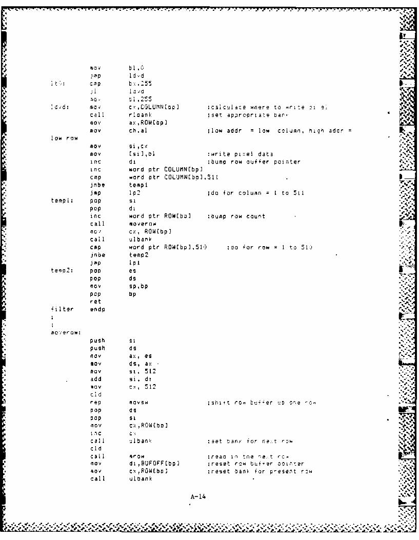
Ib
, mp Id'dit:: cIp b:.:55 I--
idvd: moV c.",CGLUMN[ooJ ;calculaze where to W rite -1 e
Call rloank :set approprialte oanr:
ax ,ROWIbp Imov chal ;low addr = low column, h1h ador =
* low row11oV si ,cMoV Lsi],bl ;write pi el dataINinc di ;bump row buffer pointer .inc word ptr COLUMN~bp]cmp word ptr COLUMN[bQ],511jnbe temp i
imp Ip2 ;do for column = 1 to 5 11 v.
tempi: pop s ,pop d i .r e
inc word ptr ROW[bo] :ump row countcall moverownov cx, ROW~bp-call ulbankcMp word ptr ROW[bp],51) :oo Zor row = ton 51!)jnbe temp2 "".mpi
teip2: pop espop ds'nov sp bp,pop bpret
'ilter endp
no ier w:push sipush ds,nov ax, es
mov 4s, axMov si, 512add si, dilov c , 512 " -c I d "'.-
rep movsw ;ahitt ro L e r o e _. r" epop dspop Si .*
'AoV c;, ROWCbp.I "I ,c' %
) %
all ulban: :set Iar, for ret r ow % ,
oldc aI ,'row :rea 1 tne e.. t ,.,Mal di,BUFOFF[bp] ;reset row buifer ooini.er-Iov cx,POW[boJ :reset bank. for present rnwcall ulbank
:-%,A-14
54.* 5," 'F ",€ ' #" . ' - -' , it" . , d #' ,€ , .*. ' " € , " -
'' , . . - ,', . . . ., . . • • - ' -
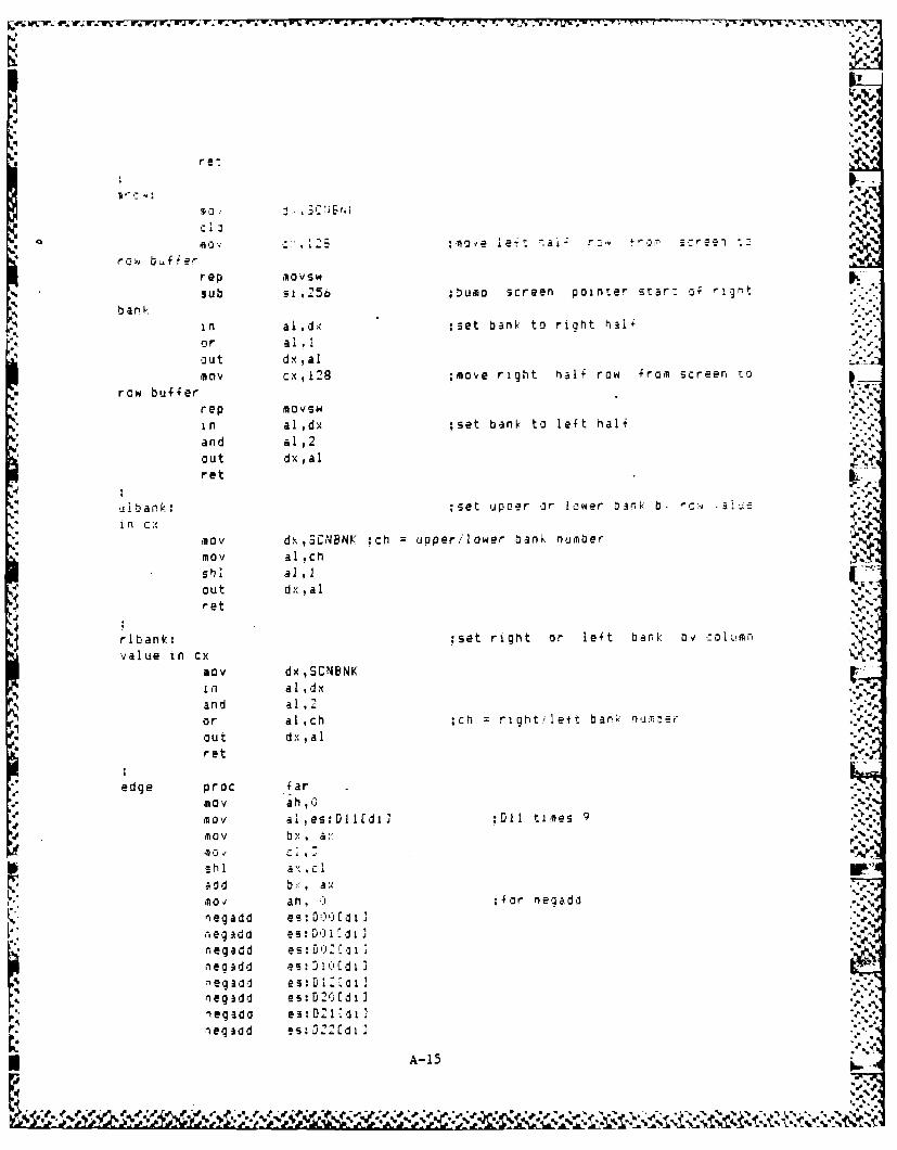
-OU W- I.; rW;. 4P. 'k % . .r- -r
rQ 4 b4 ,4e.
rep ,ovsw
".sub 51 , 250 ;u m screen Pointer star7 o; r gt..-
~~~b a n k ":.... ~in al,dx :set bank: to riaht hal ''-:
,' ~ ou t dx ,al . .._nov cx,12B ;move right riali raw from screen to
row buffer
rep novswin al,dx ;set bank to let hal"and a .,out dx, al
ret m.s
u b an .: ;set ,up:oer or lower ank: b. c-i -alje
i n CA ,nov dxSCNBNK oh =upper/lower bank number --P
nov a! ,oh ,.w
and al,2II i
out dx ,aI
ret
ribank: ;set right or le4t bank ov c. olumn
value in c-nov dx,SCNBNKvin al dx
and aI ,2
L or al ch ;ch right/ leti bar'.. ri-nm er ..-out dx,a I.%ret
edge proc iarnov ahN
nov a! es:Dl I di 3 :DlI times "'
MtOV b x a.. x "
shi ax. c Ia0 d ba,1o an ,+ ; or ne badd .
negadd es: V-0:[ 1.1
neg ad d e s DO 1.) 2
out~d ds , ]
n o po es - .1Cdi I
negadd es:D 20 1d ] "-Iiegada 3: D.' C d 1.negad es:D1t e
' _ A-15 ..
""' "-
,• ", :/ ' " ", , -V bx,- a ' Z ." . ., .,., , .- , • , . .-. ,.," ,:
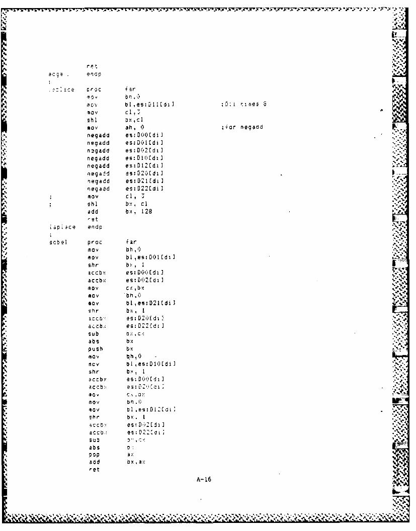
F ~- ~-hk~~-I .- -- M 1 b I ~~4~ J ~~. * 1retiyy ~ y~-;
s I ox.. cI
negad b es: 7[i IuJ;
neqadd es: D10 1d i Inegadd es:DC'2ldi]I
negaid es:D21C'di2negadd e s: D2 1Cdi I
n ne gad d e s : D IdiJI
* nov ci,
shl bx ciadd bx, 128 ~ .
i iap Ice end p
sC q proc farnov bh,()mov bl,es:DOI~diJshr b Iaccbx es DQo(Adi I
sccb- es DO' I d 1 14tio0v cx bxmov b h,mov bl,es:D21Udi)shr bx , 1
i c ri es :D2 1 (di Ia c cb; es:D2C.7di Isub 0 cabs bxp u sh bxm
nov b I es:Dl()Edilshr by , 1a c c by es: 000Cd i I
nlov b I es:Dl-'[.il .4
~hr b x.a c c b es: DI'21 Ji I
acub e E-K:.j
absPO P a;*,add b x ax4ret
A- 16
4~~~~~~~% V'%%* % . ' .. 4
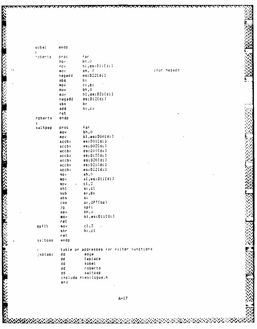
scbe 1 en d E
t-'~ fzr rie:
negadi es:D^2Edi)-ab s bx .-
d. 1OV cx bxmaybh .0
11ay blI es:D211dilnegadd es:D12(dila bsz b xadd bx cxret
rcberts endp
saltpep proc farmay bh , 0A 0v bi ,es:DOOfdi Jac cb;, e s DO IL'diIaccb? es D02 Id ia c cbx e s:D I ) Idi]Iaccbx es:Dl2fdi Iaccbx es-:D201di Iaccby es: DZIC di Iaccb/ es:D221di I
may aI,es:DII~dil1110V cl.Ishi ax, C!sub ax ,b xabs a X
c I-B pax , OFP T I b Iq spf
may bl~es:Dll~di)ret
spf 1: May cl, -
shr b,, clV. ret
--'toeo endp
table of addresses for fillter f;unctions
2-10tab: d d edg~e
%dd laplaced d sobeldd robertsdd Saltoepnclude f eoi Iogue. h
A-17 %7
% 4
4-
4-
4' *A.
V -4-4-
.J.
.4 -- S.
~.-*44
.1.44.
.1~
4'
4..
5-
-9
4 49
This page intentionally left blank.
.4
4'
SI9, -I.4.
9,
4
-5
4'
-94'
4 .1*
4. '4'*
9, ; 9~~.
A-18
* 9-...
*~4
. . . . . . .. - _ -. ...... . . .... .-. .•.. --.
DISTRIBUTION LIST
Defense Technical Information CommanderCenter (TRS) Explosive Oridnance Disposal
Cameron Station, Building 5 Group TWOAlexandria, VA 22314 2 Fort Story, VA 23459
Chief of Naval Operations Commanding Officer(OP-9821F1) Naval School Explosive Ordnance
Department of the Navy Disposal (N12)Washington, DC 20350 1 Naval Ordnance Station
Indian Head, MD 20640 2Chief of Naval Operations
(OP-372H) CommanderDepartment of the Navy U.S. Army Technical DetachmentWashington, DC 20350 1 Naval Explosive Ordnance
Disposal Technology CenterCommander Indian Head, MD 20640 3Naval Sea Systems Command D
(SEA-033) CommanderWashington, DC 20362 Detachment 63, HQ Ogden Air
Logistics Center (AFLC)Commander Naval Explosive Ordnance ..
Naval Sea Systems Command Disposal Technology Center(SEA-06X) Indian Head, MD 20640 12
Washington, DC 20362 2Officer in Charge
Commander Marine Corps Detac.hmentNaval Sea Systems Command Naval Explosive Ordnance
(SEA-OOC) Disposal Technology, CenterWashington, DC 20362 2 Indian Head, MD 20640
Commander Commanding OfficerExplosive Ordnance Disposal Naval Explosive Ordhiumce
Group ONE Disposal TechnologyBarbers Point, HI 96862 2 Center (604)
Indian Head, MD 20640 2Officer in ChargeNAVEODFLTLAIU HeadquartersNaval Explosive Ordnance ARDC (Attn: DRSMC-LCU-CE (D))
Disposal Technology Center Dover, NJ 07801 .Indian Head, MD 20640 1
CommandantUSAMMCS (Attn: ATSK-CM)Redstone Arsenal, AL 35897 1
V
-.' .5 3, .-.-.- .-- ,-' . . '- .- ,: .. -. . . ,. , - - - . , . .... . . ... . . ,:
S~ .r~ ~ ~ -.p -~ -~ -.p -~ -. ~ ~ -j~ .~ ~
4-
4-
C
'S.
I'.
.4,
.9
.p.-S.
-.4.
-p.
S..-'.5.
,%. ~5g
*..5p..S.. .4* .p.. /
Up.,
~'