Embed Size (px)
Citation preview
JOHNS HOPKINS APL TECHNICAL DIGEST, VOLUME 32, NUMBER 3 (2013) 595
INTRODUCTIONDuring the past decade, unmanned ground vehicle
(UGV) systems have been used successfully by military services and are increasingly being used to conduct dangerous and life-threatening tasks for law enforce-ment as well as first responder and disaster relief efforts
around the world. As the application of UGV systems becomes more pervasive, their deployment and life cycle logistics support become major concerns. As UGV missions call for execution of more complex tasks, it becomes necessary to integrate advanced technolo-
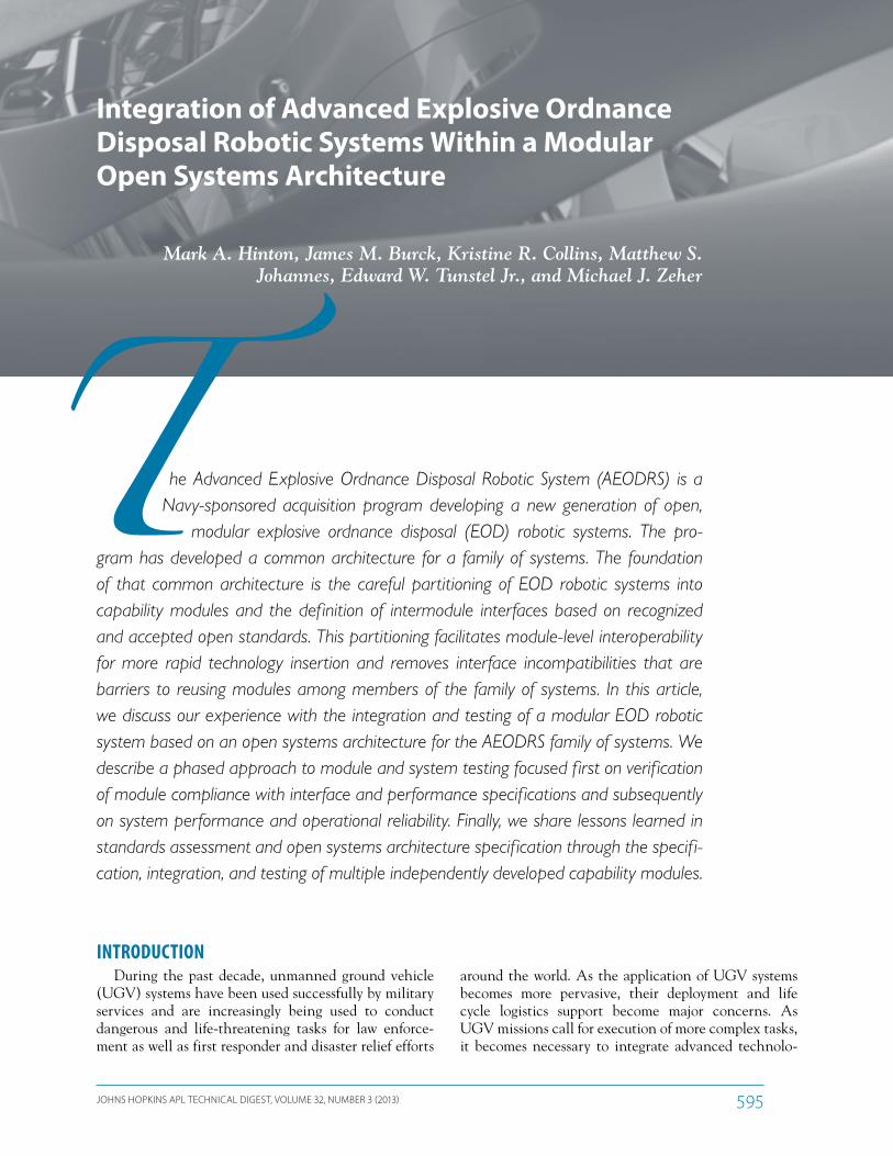
he Advanced Explosive Ordnance Disposal Robotic System (AEODRS) is a Navy-sponsored acquisition program developing a new generation of open,
modular explosive ordnance disposal (EOD) robotic systems. The pro-gram has developed a common architecture for a family of systems. The foundation of that common architecture is the careful partitioning of EOD robotic systems into capability modules and the definition of intermodule interfaces based on recognized and accepted open standards. This partitioning facilitates module-level interoperability for more rapid technology insertion and removes interface incompatibilities that are barriers to reusing modules among members of the family of systems. In this article, we discuss our experience with the integration and testing of a modular EOD robotic system based on an open systems architecture for the AEODRS family of systems. We describe a phased approach to module and system testing focused first on verif ication of module compliance with interface and performance specifications and subsequently on system performance and operational reliability. Finally, we share lessons learned in standards assessment and open systems architecture specification through the specifi-cation, integration, and testing of multiple independently developed capability modules.
Integration of Advanced Explosive Ordnance Disposal Robotic Systems Within a Modular Open Systems Architecture
Mark A. Hinton, James M. Burck, Kristine R. Collins, Matthew S. Johannes, Edward W. Tunstel Jr., and Michael J. Zeher
M. A. HINTON ET AL.
JOHNS HOPKINS APL TECHNICAL DIGEST, VOLUME 32, NUMBER 3 (2013)596
THE AEODRS FAMILY OF SYSTEMSThe AEODRS program conducted a study of EOD
mission types. This study, conducted by Penn State’s Applied Research Laboratory, concluded that the EOD mission space could best be addressed by a family of three classes of UGV systems based on a common architec-ture that would enable maximizing reuse of components between the family of systems (FoS) members to reduce the cost of supporting the FoS in theater. The FoS resulting from this analysis comprises the dismounted operations system, the tactical operations system, and the base/infrastructure operations system.
gies and control schemes. Meeting these challenges is complicated by a lack of interoperability between UGV subsystems, which imposes limitations on devel-opment and deployment. These challenges are being addressed by the Advanced Explosive Ordnance Dis-posal Robotic System (AEODRS) program, which has a primary goal to develop a common architecture for a family of UGV systems to enable unprecedented levels of interoperability.
AEODRS is a Joint Service Explosive Ordnance Dis-posal (JSEOD) program, executed through the Naval Explosive Ordnance Disposal Technology Division (NAVEODTECHDIV) via the Navy Program Manage-ment Office for Explosive Ordnance Disposal/Coun-ter Remote Controlled Improvised Explosive Device Electronic Warfare (PMS-408). The foundation of the AEODRS common architecture is the careful partition-ing of explosive ordnance disposal (EOD) robotic sys-tems into capability modules (CMs; subsystems serving specific functions within the vehicle architecture) and the definition of common intermodule interfaces at the physical, electrical, and logical levels, all based on recog-nized and accepted open standards.1 The parallel concept of an open systems business model, in which the govern-ment owns and controls the architecture definition and the specifications of the intermodule interfaces, is criti-cal to understanding and successful implementation of such a modular, open system. In a previous Johns Hopkins APL Technical Digest article,2 we introduced the common architecture and described an implementation approach that would demonstrate its contribution to subsystem and payload interoperability. We presented a strategy for incremental integration and testing of independently developed subsystems and payloads leveraging a mixed-simulation system test bed to enable independent assess-ment of their architectural compliance. This incremen-tal integration and test strat-egy also reduces integration schedule dependencies on the order in which the indepen-dently developed subsystems and payloads are delivered for integration.3
This article focuses on the experience gained thus far and the lessons learned while assessing architectural com-pliance and performing the integration of independently developed CMs delivered by multiple vendors.
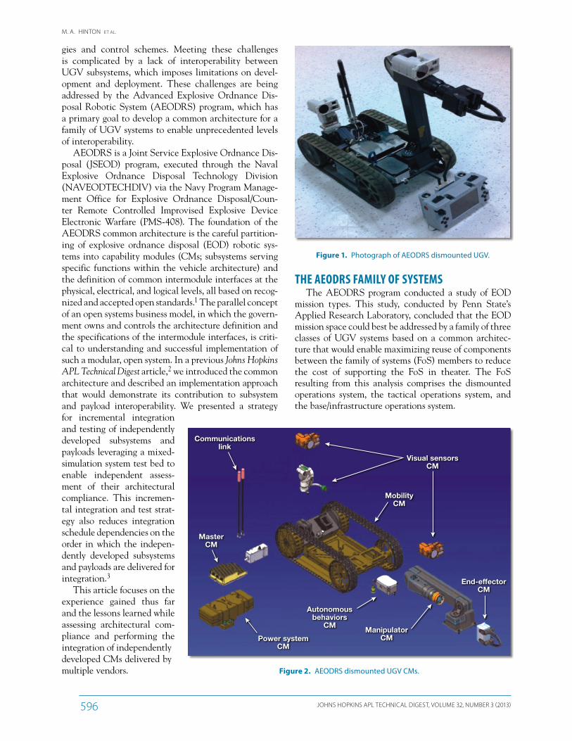
Figure 1. Photograph of AEODRS dismounted UGV.
Communicationslink
MasterCM
MobilityCM
Visual sensorsCM
ManipulatorCM
Autonomousbehaviors
CM
Power systemCM
End-effectorCM
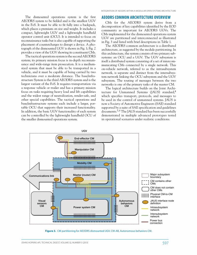
Figure 2. AEODRS dismounted UGV CMs.
INTEGRATION OF AEODRS WITHIN A MODULAR OPEN SYSTEMS ARCHITECTURE
JOHNS HOPKINS APL TECHNICAL DIGEST, VOLUME 32, NUMBER 3 (2013) 597
AEODRS COMMON ARCHITECTURE OVERVIEWCMs for the AEODRS system derive from a
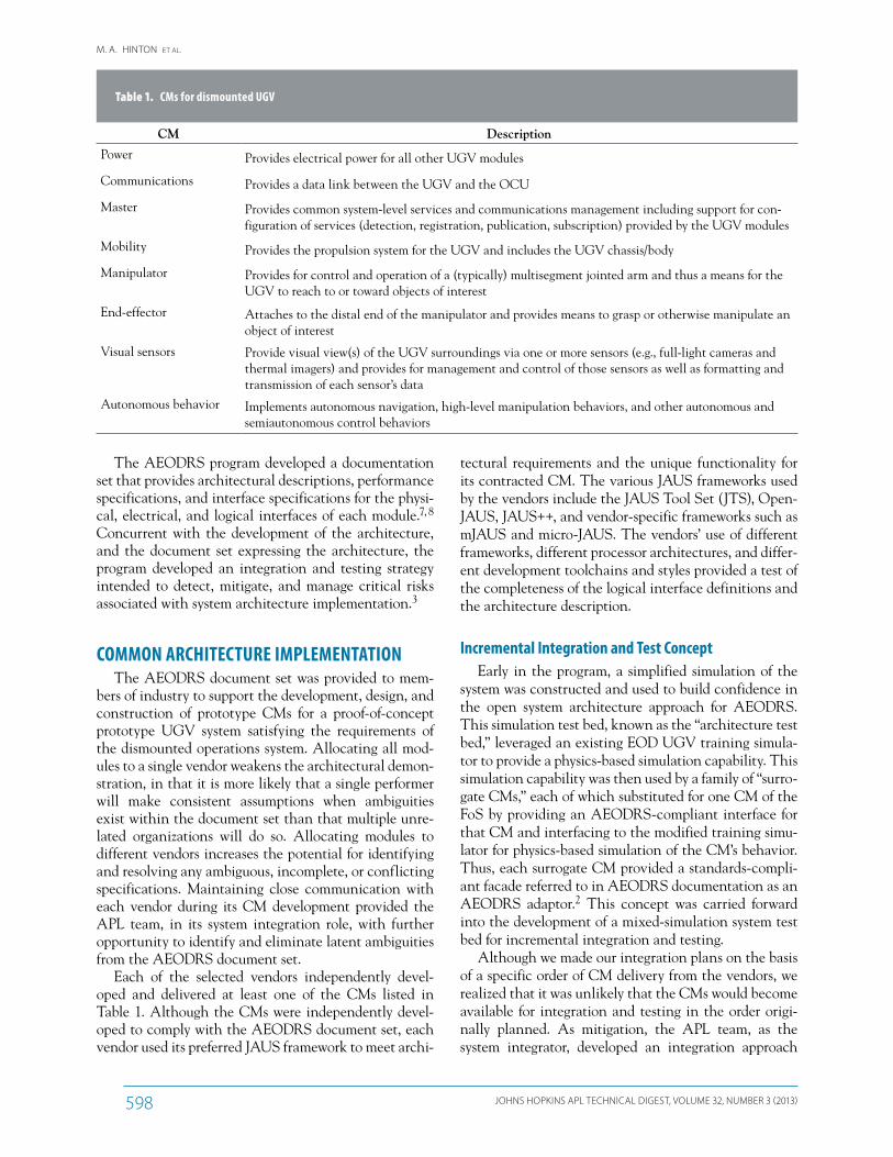
de composition of key capabilities identified by the EOD community as important for AEODRS UGVs. The CMs implemented for the dismounted operations system UGV are partitioned and interconnected as illustrated in Fig. 3 and listed with brief descriptions in Table 1.
The AEODRS common architecture is a distributed architecture, as suggested by the module partitioning. In this architecture, the system consists of two primary sub-systems: an OCU and a UGV. The UGV subsystem is itself a distributed system consisting of a set of intercom-municating CMs connected by a single network. This on-vehicle network, referred to as the intrasubsystem network, is separate and distinct from the intersubsys-tem network linking the OCU subsystem and the UGV subsystem. The routing of messages between the two networks is one of the primary tasks of the master CM.
The logical architecture builds on the Joint Archi-tecture for Unmanned Systems (JAUS) standard,4 which specifies transport, protocols, and messages to be used in the control of unmanned systems. JAUS is now a Society of Automotive Engineers (SAE) standard supported by a suite of SAE specification and guidelines documents.5, 6 The JAUS standard has been successfully demonstrated in multiple advanced prototypes tested in operational scenarios under realistic conditions.
The dismounted operations system is the first AEODRS system to be fielded and is the smallest UGV in the FoS. It must be able to fit fully into a backpack, which places a premium on size and weight. It includes a compact, lightweight UGV and a lightweight handheld operator control unit (OCU). It is intended to focus on reconnaissance tasks but is also capable of supporting the placement of countercharges to disrupt a device. A pho-tograph of the dismounted UGV is shown in Fig. 1; Fig. 2 provides a view of the UGV showing its constituent CMs.
The tactical operations system is the second AEODRS system; its primary mission focus is in-depth reconnais-sance and wide-range item prosecution. It is a medium-sized system that must be able to be transported in a vehicle, and it must be capable of being carried by two technicians over a moderate distance. The base/infra-structure System is the third AEODRS system and is the largest variant of the FoS. It requires transportation via a response vehicle or trailer and has a primary mission focus on tasks requiring heavy load and lift capabilities and the widest range of neutralization, render-safe, and other special capabilities. The tactical operations and base/infrastructure systems each include a larger, por-table OCU that supports their increased functionality. In addition, the basic UGV functionality of each system can be controlled by the lightweight handheld OCU of the smaller dismounted operations system.
End-effector CM
UGV
Manipulator CM
Visualsensors
CM
Autonomousbehaviors
CM
Communications link
Mobility CM
Master (router) CM
Power system CM
Physical CM-to-CMinterfaceJAUS interface nodedefinitionIntrasubsystemnetworkIntersubsystemnetworkPower busconnection
Major subsystemboundaryCM contains otherCMsCM does not containother CMs
Figure 3. CM partitioning for AEODRS dismounted UGV. CM-AB, Autonomous behaviors CM.
M. A. HINTON ET AL.
JOHNS HOPKINS APL TECHNICAL DIGEST, VOLUME 32, NUMBER 3 (2013)598
tectural requirements and the unique functionality for its contracted CM. The various JAUS frameworks used by the vendors include the JAUS Tool Set (JTS), Open-JAUS, JAUS++, and vendor-specific frameworks such as mJAUS and micro-JAUS. The vendors’ use of different frameworks, different processor architectures, and differ-ent development toolchains and styles provided a test of the completeness of the logical interface definitions and the architecture description.
Incremental Integration and Test ConceptEarly in the program, a simplified simulation of the
system was constructed and used to build confidence in the open system architecture approach for AEODRS. This simulation test bed, known as the “architecture test bed,” leveraged an existing EOD UGV training simula-tor to provide a physics-based simulation capability. This simulation capability was then used by a family of “surro-gate CMs,” each of which substituted for one CM of the FoS by providing an AEODRS-compliant interface for that CM and interfacing to the modified training simu-lator for physics-based simulation of the CM’s behavior. Thus, each surrogate CM provided a standards-compli-ant facade referred to in AEODRS documentation as an AEODRS adaptor.2 This concept was carried forward into the development of a mixed-simulation system test bed for incremental integration and testing.
Although we made our integration plans on the basis of a specific order of CM delivery from the vendors, we realized that it was unlikely that the CMs would become available for integration and testing in the order origi-nally planned. As mitigation, the APL team, as the system integrator, developed an integration approach
The AEODRS program developed a documentation set that provides architectural descriptions, performance specifications, and interface specifications for the physi-cal, electrical, and logical interfaces of each module.7, 8 Concurrent with the development of the architecture, and the document set expressing the architecture, the program developed an integration and testing strategy intended to detect, mitigate, and manage critical risks associated with system architecture implementation.3
COMMON ARCHITECTURE IMPLEMENTATIONThe AEODRS document set was provided to mem-
bers of industry to support the development, design, and construction of prototype CMs for a proof-of-concept prototype UGV system satisfying the requirements of the dismounted operations system. Allocating all mod-ules to a single vendor weakens the architectural demon-stration, in that it is more likely that a single performer will make consistent assumptions when ambiguities exist within the document set than that multiple unre-lated organizations will do so. Allocating modules to different vendors increases the potential for identifying and resolving any ambiguous, incomplete, or conflicting specifications. Maintaining close communication with each vendor during its CM development provided the APL team, in its system integration role, with further opportunity to identify and eliminate latent ambiguities from the AEODRS document set.
Each of the selected vendors independently devel-oped and delivered at least one of the CMs listed in Table 1. Although the CMs were independently devel-oped to comply with the AEODRS document set, each vendor used its preferred JAUS framework to meet archi-
Table 1. CMs for dismounted UGV
CM Description
Power Provides electrical power for all other UGV modules
Communications Provides a data link between the UGV and the OCU
Master Provides common system-level services and communications management including support for con-figuration of services (detection, registration, publication, subscription) provided by the UGV modules
Mobility Provides the propulsion system for the UGV and includes the UGV chassis/body
Manipulator Provides for control and operation of a (typically) multisegment jointed arm and thus a means for the UGV to reach to or toward objects of interest
End-effector Attaches to the distal end of the manipulator and provides means to grasp or otherwise manipulate an object of interest
Visual sensors Provide visual view(s) of the UGV surroundings via one or more sensors (e.g., full-light cameras and thermal imagers) and provides for management and control of those sensors as well as formatting and transmission of each sensor’s data
Autonomous behavior Implements autonomous navigation, high-level manipulation behaviors, and other autonomous and semiautonomous control behaviors
INTEGRATION OF AEODRS WITHIN A MODULAR OPEN SYSTEMS ARCHITECTURE
JOHNS HOPKINS APL TECHNICAL DIGEST, VOLUME 32, NUMBER 3 (2013) 599
Basic ConfigurationThe system test bed used COTS computer hardware
as the platform for the OCU subsystem. This “desk-top OCU” was used to host the OCU software devel-oped by Space and Naval Warfare Systems Command (SPAWAR) Systems Center as a variant of SPAWAR’s Multi-Robot OCU (MOCU).9
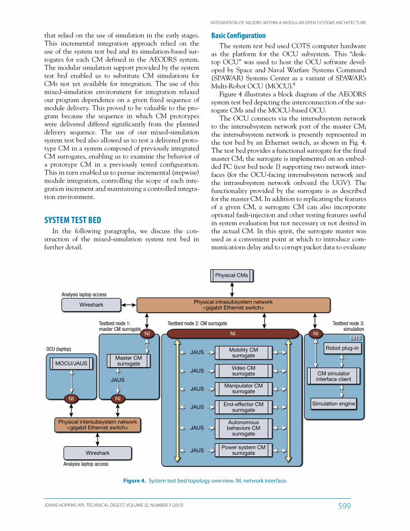
Figure 4 illustrates a block diagram of the AEODRS system test bed depicting the interconnection of the sur-rogate CMs and the MOCU-based OCU.
The OCU connects via the intersubsystem network to the intersubsystem network port of the master CM; the intersubsystem network is presently represented in the test bed by an Ethernet switch, as shown in Fig. 4. The test bed provides a functional surrogate for the final master CM; the surrogate is implemented on an embed-ded PC (test bed node 1) supporting two network inter-faces (for the OCU-facing intersubsystem network and the intrasubsystem network onboard the UGV). The functionality provided by the surrogate is as described for the master CM. In addition to replicating the features of a given CM, a surrogate CM can also incorporate optional fault-injection and other testing features useful in system evaluation but not necessary or not desired in the actual CM. In this spirit, the surrogate master was used as a convenient point at which to introduce com-munications delay and to corrupt packet data to evaluate
that relied on the use of simulation in the early stages. This incremental integration approach relied on the use of the system test bed and its simulation-based sur-rogates for each CM defined in the AEODRS system. The modular simulation support provided by the system test bed enabled us to substitute CM simulations for CMs not yet available for integration. The use of this mixed-simulation environment for integration relaxed our program dependence on a given fixed sequence of module delivery. This proved to be valuable to the pro-gram because the sequence in which CM prototypes were delivered differed significantly from the planned delivery sequence. The use of our mixed-simulation system test bed also allowed us to test a delivered proto-type CM in a system composed of previously integrated CM surrogates, enabling us to examine the behavior of a prototype CM in a previously tested configuration. This in turn enabled us to pursue incremental (stepwise) module integration, controlling the scope of each inte-gration increment and maintaining a controlled integra-tion environment.
SYSTEM TEST BEDIn the following paragraphs, we discuss the con-
struction of the mixed-simulation system test bed in further detail.
Physical CMs
MOCU/JAUS
Robot plug-in
Simulation engine
Master CMsurrogate
CM simulatorinterface client
Physical intrasubsystem network<gigabit Ethernet switch>
Physical intersubsystem network<gigabit Ethernet switch>
Wireshark
Analysis laptop access
Wireshark
Analysis laptop access
OCU (laptop)
ERTS
Testbed node 1:master CM surrogate
Testbed node 2: CM surrogate Testbed node 3:simulation
NI NI NI
NINI
JAUS
Mobility CMsurrogate
Video CMsurrogate
Manipulator CMsurrogate
End-effector CMsurrogate
Power system CMsurrogate
Autonomousbehaviors CM
surrogate
JAUS
JAUS
JAUS
JAUS
JAUS
JAUS
Figure 4. System test bed topology overview. NI, network interface.
M. A. HINTON ET AL.
JOHNS HOPKINS APL TECHNICAL DIGEST, VOLUME 32, NUMBER 3 (2013)600
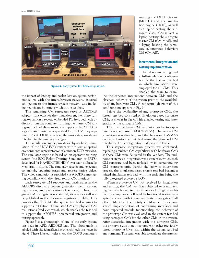
running the OCU software (MOCU) and the simula-tion engine (ERTS), as well as a laptop hosting the sur-rogate CMs (CM-server), a laptop hosting the surrogate master CM (CM-MAS), and a laptop hosting the surro-gate autonomous behaviors CM (CM-AB).
Incremental Integration and Testing Implementation
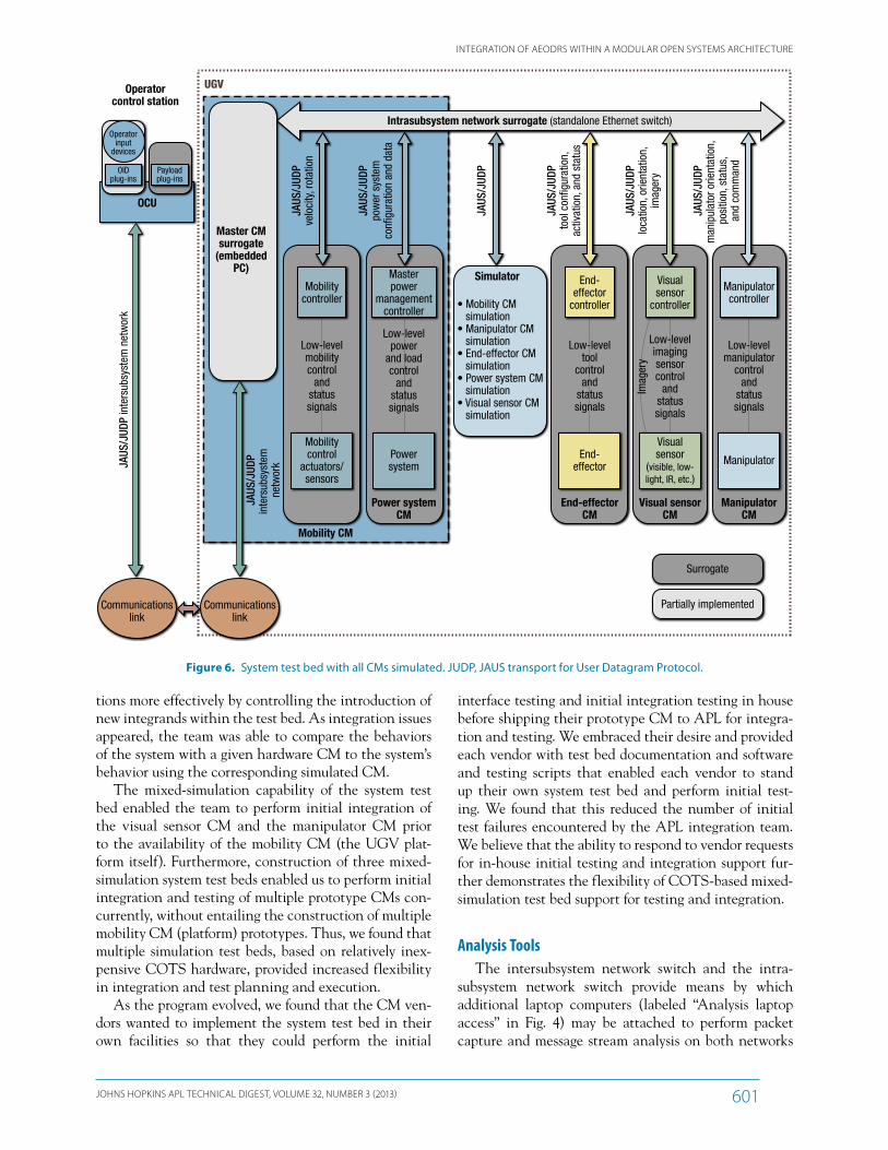
Initial system testing used a full-simulation configura-tion of the system test bed in which simulations were employed for all CMs. This enabled the team to exam-
ine the expected interactions between CMs and the observed behavior of the system prior to the availabil-ity of any hardware CMs. A conceptual diagram of this configuration appears in Fig. 6.
Before the availability of any prototype CMs, the system test bed consisted of simulation-based surrogate CMs, as shown in Fig. 6. This enabled testing and inte-gration of the surrogate CMs.
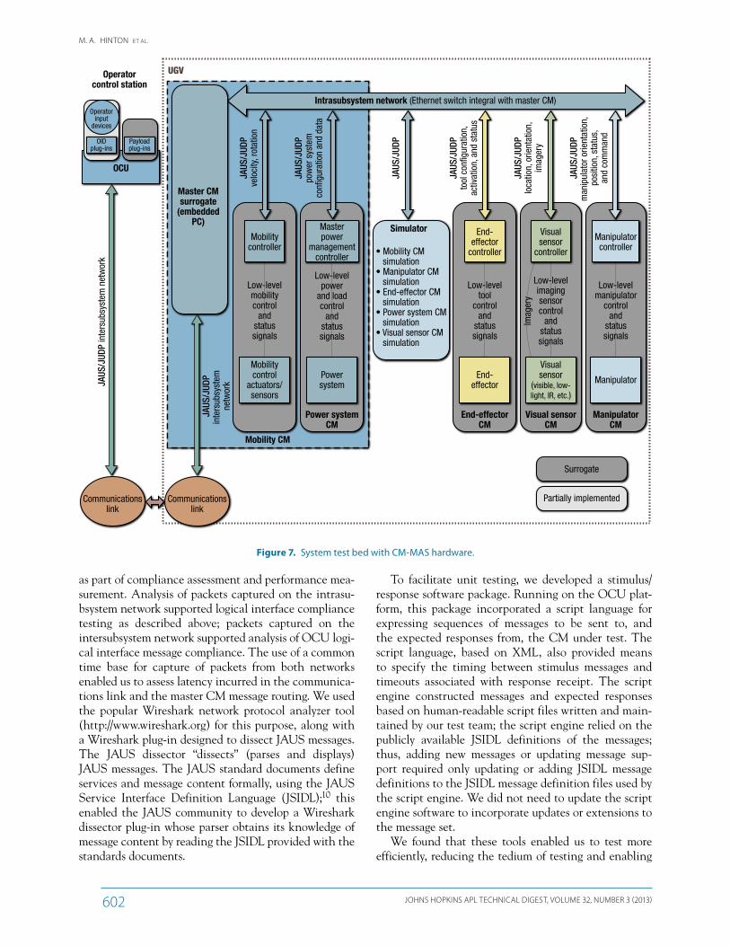
The first hardware CM realization to be incorpo-rated was the master CM (CM-MAS). The master CM simulation was disabled, and the hardware CM-MAS connected into the test bed using the standard CM interfaces. This configuration is depicted in Fig. 7.
This stepwise integration process was continued, replacing simulated CM capabilities with hardware CMs as those CMs were delivered by the vendors. The end-point of stepwise integration was a system in which each CM surrogate had been replaced by its corresponding CM prototype unit. During the stepwise integration process, the simulation-based system test bed became a mixed-simulation test bed, with the endpoint being the fully integrated prototype UGV.
When a prototype CM was received for integration and testing, the CM was first subjected to a unit test regime, which exercised its interfaces for logical archi-tecture compliance, followed by functional testing in a system context with known and tested surrogates of all other CMs. Once the prototype CM under test demon-strated implementation of conforming interfaces and basic expected module functionality, the behavior of the prototype CM was evaluated in the system test bed using surrogate CMs for the other CMs in the system. After successful integration with the surrogate CMs, the prototype was then integrated with other previously tested prototype CMs, still within the system test bed environment. The team was able to evaluate the interac-
the impact of latency and packet loss on system perfor-mance. As with the intersubsystem network, external connection to the intrasubsystem network was imple-mented via an Ethernet switch in the test bed.
The remaining CM surrogates serve as AEODRS adaptor front ends for the simulation engine; these sur-rogates run on a second embedded PC (test bed node 2) distinct from the computer running the master CM sur-rogate. Each of these surrogates supports the AEODRS logical system interfaces specified for the CM they rep-resent. As AEODRS adaptors, the surrogates provide an interface to the simulation engine.
The simulation engine provides a physics-based simu-lation of the UGV EOD system within virtual spatial environments representative of common EOD missions. The simulator engine is based on an operator training system (the EOD Robot Training Simulator, or ERTS) developed for NAVEODTECHDIV by a team at Battelle Memorial Institute. The simulator accepts and executes commands, updating status and representative video. The video simulation is provided via AEODRS messag-ing compliant with the visual sensor CM interfaces.
Each surrogate CM supports and participates in the AEODRS discovery process (detection, identification, registration, and publication of services). Thus, if a given CM surrogate is not started, its services will not be published in the discovery registration tables. This provides the flexibility the system test bed requires to support substitution of simulated CMs for physical CM realizations (and vice versa), which enables the test bed to support the AEODRS incremental integration and testing approach.
Figure 5 is a photograph of one of the early system test beds in APL’s AEODRS Lab. The photograph is labeled with the identification of each node as shown in Fig. 4. These labeled nodes show the COTS computers
MOCUERTS
Subsystemnetworkswitches
Inter Intra
Ethernet cables
Powerstrips
CM-server CM-MAS
Handheld controller
CM-AB
Figure 5. Early system test bed configuration.
INTEGRATION OF AEODRS WITHIN A MODULAR OPEN SYSTEMS ARCHITECTURE
JOHNS HOPKINS APL TECHNICAL DIGEST, VOLUME 32, NUMBER 3 (2013) 601
interface testing and initial integration testing in house before shipping their prototype CM to APL for integra-tion and testing. We embraced their desire and provided each vendor with test bed documentation and software and testing scripts that enabled each vendor to stand up their own system test bed and perform initial test-ing. We found that this reduced the number of initial test failures encountered by the APL integration team. We believe that the ability to respond to vendor requests for in-house initial testing and integration support fur-ther demonstrates the flexibility of COTS-based mixed-simulation test bed support for testing and integration.
Analysis ToolsThe intersubsystem network switch and the intra-
subsystem network switch provide means by which additional laptop computers (labeled “Analysis laptop access” in Fig. 4) may be attached to perform packet capture and message stream analysis on both networks
tions more effectively by controlling the introduction of new integrands within the test bed. As integration issues appeared, the team was able to compare the behaviors of the system with a given hardware CM to the system’s behavior using the corresponding simulated CM.
The mixed-simulation capability of the system test bed enabled the team to perform initial integration of the visual sensor CM and the manipulator CM prior to the availability of the mobility CM (the UGV plat-form itself). Furthermore, construction of three mixed-simulation system test beds enabled us to perform initial integration and testing of multiple prototype CMs con-currently, without entailing the construction of multiple mobility CM (platform) prototypes. Thus, we found that multiple simulation test beds, based on relatively inex-pensive COTS hardware, provided increased flexibility in integration and test planning and execution.
As the program evolved, we found that the CM ven-dors wanted to implement the system test bed in their own facilities so that they could perform the initial
Power systemCM
Mobility CM
Manipulatorcontroller
Manipulator
ManipulatorCM
Low-levelmanipulator
controland
statussignals
End-effector
End-effector
controller
End-effectorCM
Low-leveltool
controland
statussignals
JAUS
/JUD
P in
ters
ubsy
stem
net
wor
k
Operatorcontrol station
OCU
UGV
Intrasubsystem network surrogate (standalone Ethernet switch)
JAUS
/JUD
Pin
ters
ubsy
stem
ne
twor
k
JAUS
/JUD
Pve
loci
ty, r
otat
ion
JAUS
/JUD
Ppo
wer
sys
tem
con�
gura
tion
and
data
JAUS
/JUD
Plo
catio
n, o
rient
atio
n,im
ager
y
JAUS
/JUD
Pto
ol c
on�g
urat
ion,
activ
atio
n, a
nd s
tatu
s
JAUS
/JUD
Pm
anip
ulat
or o
rient
atio
n,
posi
tion,
sta
tus,
and
com
man
d
Master CMsurrogate
(embeddedPC)
Communicationslink
Communicationslink
Partially implemented
Surrogate
Visual sensorCM
Imag
ery
JAUS
/JUD
P
Operatorinput
devices
OIDplug-ins
Payloadplug-ins
Simulator
• Mobility CM simulation• Manipulator CM simulation• End-effector CM simulation• Power system CM simulation• Visual sensor CM simulation
Visualsensor
controller
Visualsensor
(visible, low-light, IR, etc.)
Low-levelimagingsensorcontrol
andstatussignals
Low-levelpower
and loadcontrol
andstatussignals
Masterpower
managementcontroller
Powersystem
Low-levelmobilitycontrol
andstatussignals
Mobilitycontroller
Mobilitycontrol
actuators/sensors
Figure 6. System test bed with all CMs simulated. JUDP, JAUS transport for User Datagram Protocol.
M. A. HINTON ET AL.
JOHNS HOPKINS APL TECHNICAL DIGEST, VOLUME 32, NUMBER 3 (2013)602
To facilitate unit testing, we developed a stimulus/response software package. Running on the OCU plat-form, this package incorporated a script language for expressing sequences of messages to be sent to, and the expected responses from, the CM under test. The script language, based on XML, also provided means to specify the timing between stimulus messages and timeouts associated with response receipt. The script engine constructed messages and expected responses based on human-readable script files written and main-tained by our test team; the script engine relied on the publicly available JSIDL definitions of the messages; thus, adding new messages or updating message sup-port required only updating or adding JSIDL message definitions to the JSIDL message definition files used by the script engine. We did not need to update the script engine software to incorporate updates or extensions to the message set.
We found that these tools enabled us to test more efficiently, reducing the tedium of testing and enabling
as part of compliance assessment and performance mea-surement. Analysis of packets captured on the intrasu-bsystem network supported logical interface compliance testing as described above; packets captured on the intersubsystem network supported analysis of OCU logi-cal interface message compliance. The use of a common time base for capture of packets from both networks enabled us to assess latency incurred in the communica-tions link and the master CM message routing. We used the popular Wireshark network protocol analyzer tool (http://www.wireshark.org) for this purpose, along with a Wireshark plug-in designed to dissect JAUS messages. The JAUS dissector “dissects” (parses and displays) JAUS messages. The JAUS standard documents define services and message content formally, using the JAUS Service Interface Definition Language (JSIDL);10 this enabled the JAUS community to develop a Wireshark dissector plug-in whose parser obtains its knowledge of message content by reading the JSIDL provided with the standards documents.
Power systemCM
Manipulatorcontroller
Manipulator
ManipulatorCM
Low-levelmanipulator
controland
statussignals
End-effector
End-effector
controller
End-effectorCM
Low-leveltool
controland
statussignals
JAUS
/JUD
P in
ters
ubsy
stem
net
wor
k
Operatorcontrol station
OCU
UGV
Intrasubsystem network (Ethernet switch integral with master CM)
JAUS
/JUD
Pin
ters
ubsy
stem
ne
twor
k
JAUS
/JUD
Pve
loci
ty, r
otat
ion
JAUS
/JUD
Ppo
wer
sys
tem
con�
gura
tion
and
data
JAUS
/JUD
Plo
catio
n, o
rient
atio
n,im
ager
y
JAUS
/JUD
Pto
ol c
on�g
urat
ion,
activ
atio
n, a
nd s
tatu
s
JAUS
/JUD
Pm
anip
ulat
or o
rient
atio
n,
posi
tion,
sta
tus,
and
com
man
d
Master CMsurrogate
(embeddedPC)
Communicationslink
Communicationslink
Partially implemented
Surrogate
Visual sensorCM
Imag
ery
JAUS
/JUD
P
Operatorinput
devices
OIDplug-ins
Payloadplug-ins
Simulator
• Mobility CM simulation• Manipulator CM simulation• End-effector CM simulation• Power system CM simulation• Visual sensor CM simulation
Visualsensor
controller
Low-levelimagingsensorcontrol
andstatussignals
Visualsensor
(visible, low-light, IR, etc.)
Mobility CM
Low-levelmobilitycontrol
andstatussignals
Mobilitycontroller
Mobilitycontrol
actuators/sensors
Low-levelpower
and loadcontrol
andstatussignals
Masterpower
managementcontroller
Powersystem
Figure 7. System test bed with CM-MAS hardware.
INTEGRATION OF AEODRS WITHIN A MODULAR OPEN SYSTEMS ARCHITECTURE
JOHNS HOPKINS APL TECHNICAL DIGEST, VOLUME 32, NUMBER 3 (2013) 603
the number of issues encountered during system integration. Providing a system test bed that sup-ports testing of an individual CM in isolation from other vendor CMs is valuable.
4. Early testing uncovered omissions in the early architecture definition document for the AEODRS common architecture (ADD-CA). Through this testing, we identified weaknesses in the JAUS dis-covery process and added guidance to the ADD-CA to assure robust, complete registration of services. Independent CM development resulting in indepen-dent discovery implementations, followed by careful system integration testing and analysis, made it pos-sible to isolate these issues and track them to the root cause in a timely manner.
5. Despite document review efforts by APL and our partners in the AEODRS system development and integration team (SDIT), inconsistencies in elec-trical interface definitions remained in the initial release of the document set. Interface inconsisten-cies are possible, so it is important to exercise all interfaces—logical, electrical, and physical—during unit testing and early system integration testing.
6. Our system test bed configuration implemented the intersubsystem network and the intrasubsystem net-work using simple managed Ethernet switches. This enabled us to use port mirroring for packet capture and logging. This, in turn, enabled us to configure our packet capture to encompass all packets on the network, or all packet traffic to and from a specific CM. This proved a valuable feature in investigation of interactions between CMs.
7. At the system performance testing stage, we found it necessary to isolate latencies associated with the propagation of video packets through the system. We found that use of a dual-homed analysis workstation configuration (supporting connections to two differ-ent networks by means of two independent network interfaces), with packet capture software capable of concurrent capture from multiple network interfaces using a common time base, simplified our latency analysis efforts significantly.
8. We encouraged each module vendor to assemble a copy of our mixed-simulation system test bed and provided them with copies of our stimulus/response testing package; this enabled the module vendors to perform development testing and predelivery test-ing equivalent to our own. The vendors embraced the mixed-simulation test bed and tools. The APL team and the vendor teams all believe that their pre-testing accelerated the system integration effort at APL and reduced the need for vendor personnel to be present through integration.
us to focus more effectively on the testing of the system, less distracted by the “care and feeding” of our tools.
LESSONS LEARNEDThe pre-prototype integration exercise has provided
feedback and refinement for the architecture, its inter-face definitions, and the associated documentation. In the following paragraphs, we share a few of the broader lessons, which should be applicable to other projects seeking to develop and implement a modular open sys-tems architecture.
1. Our pre-prototype strategy involved subcontract-ing the development of the individual CMs to mul-tiple independent vendors. We felt that ambiguities in specifications are often bridged by the reader’s assumptions and that a single developer would likely make consistent assumptions, with the result that ambiguities would not be exposed during prototype development. For the best verification of interface specification completeness, we felt it best that the prototype modules be implemented on at least two different processor architecture platforms using at least two different JAUS frameworks and software development toolchains. In our system integration efforts, we uncovered several minor incompatibili-ties between the JAUS frameworks our vendors used. Early CM unit testing within the mixed-simulation test bed enabled us to quickly identify the incom-patibilities. In all cases, the incompatibilities were avoidable and could be mitigated by providing guid-ance in the use of framework features not required for successful implementation.
2. Early exposure contributed to identifying issues with the DHCP client configuration for the intersubsys-tem network interface of CM-MAS. Insufficient client configuration guidance had been provided in the interface control document for CM-MAS. After initial testing at APL, guidance was added to the document and provided to the vendor. Similar issues were identified and resolved with respect to DHCP lease parameters for the DHCP intersubsystem net-work server (provided by the MOCU subsystem) and the DHCP intrasubsystem network server (provided by CM-MAS). Again, the critical observation is that such issues are readily resolved when identified early; early exposure, both by document reviews and by early testing facilitated by the mixed-simulation test bed, is helpful.
3. Successful unit testing of each CM (including the exercise of interfaces, and specifically the exercise of all specified messages) before integration of that CM reduced system integration. Thorough unit testing in the controlled test bed environment minimizes
M. A. HINTON ET AL.
JOHNS HOPKINS APL TECHNICAL DIGEST, VOLUME 32, NUMBER 3 (2013)604
Disposal Robotic Systems (AEODRS) Family of Unmanned Ground Vehicles,” in Proc. 2010 NDIA Ground Vehicle Systems Engineering and Technology Symp., Vehicle Electronics and Architec-ture (VEA) Mini-Symp., Dearborn, MI, paper 213 (2010).
2Hinton, M. A., Zeher, M. J., Kozlowski, M. V., and Johannes, M. S., “Advanced Explosive Ordnance Disposal Robotic System (AEODRS): A Common Architecture Revolution,” Johns Hopkins APL Tech. Dig. 30(3), 256–266 (2011).
3Hinton, M. A., Johannes, M. S., Zeher, M. J., and Kozlowski, M. V., “Implementing a Common Architecture for EOD Robotic Sys-tems,” in Proc. 2011 NDIA Ground Vehicle Systems Engineering and Technology Symp., Robotic Systems (RS) Mini-Symp., Dearborn, MI, paper 80 (2011).
4SAE International, JAUS History and Domain Model, Standard AIR5664, http://standards.sae.org/air5664/ (2006).
5SAE International, JAUS Core Service Set, Standard AS5710 Revision A, http://standards.sae.org/as5710a/ (2010).
6SAE International, JAUS Transport Considerations, Standard AIR5645, http://standards.sae.org/air5645/ (2007).
7“AEODRS Common Information,” EXT-AEODRS-10-2180-Common_Information Version 1.2, Naval EOD Tech-nology Division, Indian Head, MD (June 2012).
8“Architecture Description Document, AEODRS Common Architecture,” ADD-AEODRS-10-0802-CA Version 1.2, Naval EOD Technology Division, Indian Head, MD (June 2012).
9Powell, D., Gilbreath, G., and Bruch, M., “Multi-Robot Operator Control Unit for Unmanned Systems,” Defense Tech Briefs, http://www.defensetechbriefs.com/component/content/article/4867 (1 Aug 2008).
10SAE International, JAUS Service Interface Definition Language, Standard AS5684 Revision A, http://standards.sae.org/as5684a/ (2010).
9. All of the vendors were given direct access to our bug tracking tool, GForge. The GForge tool allowed us to set priorities for problem resolution and pro-vided direct feedback to the vendors on the status of the integration of their equipment. This tight loop for problem identification and resolution reduced the system integration time.
ACKNOWLEDGMENTS: The AEODRS program has benefited from the participation of several organizations within the framework of the AEODRS SDIT. The SDIT members come from the following participating organizations: NAVEODTECHDIV (Indian Head, MD); APL (Laurel, MD); Penn State University Applied Research Laboratory (State College, PA); Battelle Memorial Institute (Columbus, OH); and SPAWAR Systems Center Pacific (San Diego, CA). The integration and testing approach as well as implemen-tation and assessment activities described herein could not have been possible without the collective inno-vation, active participation, and full cooperation of all SDIT members.
REFERENCES
1Kozlowski, M. V., Hinton, M., and Johannes, M., “Toward a Common Architecture for the Advanced Explosive Ordnance
Mark A. Hinton is a member of APL’s Senior Technical Staff and serves APL’s AEODRS team as Systems Architect and as an integration lead. James M. Burck is a senior system and software engineer; he serves as the Lead Engineer for the APL system test bed and assists with systems engineering. Kristine R. Collins is a member of the APL Associate Technical Staff and serves as a contributor to the system test bed development and during system integration. Matthew S. Johannes is a member of the APL Senior Technical Staff; he serves as Lead Mechanical Engineer for the APL AEODRS team. Edward W. Tunstel Jr. is a senior robotics engineer in APL’s Research and Exploratory Development Department. Dr. Tunstel contributed to the AEODRS system test bed development and use during incremental system integration and testing and assisted with systems engineering activities. Michael J. Zeher is a member of the APL Senior Technical Staff and serves as Project Manager for APL’s AEODRS team. For further information on the work reported here, contact Mark Hinton. His e-mail address is [email protected].
The Authors
The Johns Hopkins APL Technical Digest can be accessed electronically at www.jhuapl.edu/techdigest.