Embed Size (px)
Citation preview
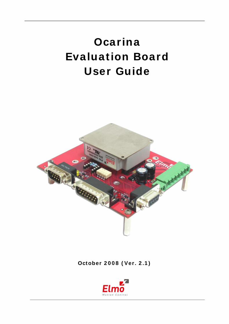
Ocarina Evaluation Board
User Guide
October 2008 (Ver. 2.1)
Notice This guide is delivered subject to the following conditions and restrictions:
This guide contains proprietary information belonging to Elmo Motion Control Ltd. Such information is supplied solely for the purpose of assisting users of the Ocarina Evaluation Board servo drive in its evaluation and testing.
The text and graphics included in this manual are for the purpose of illustration and reference only. The specifications on which they are based are subject to change without notice.
Elmo Motion Control and the Elmo Motion Control logo are trademarks of Elmo Motion Control Ltd.
Information in this document is subject to change without notice.
Document No. MAN-EVLBRD-OCA Copyright ©2008
Elmo Motion Control Ltd. All rights reserved.
Evaluation Board Catalog Number OCA-EVLBRD-1
Related Products:
Ocarina Catalog Numbers Ocarina Installation Guide Cat. No.
OCA-XX-YYY MAN-OCAIG (available on our web site)
Revision History:
Version Release Date Status Changes/Remarks
Version 2.1 October 2008 Updated MTCR 00-100-25: Added section 2.5.1.1 with clarification for connecting Ocarina/Castanet to DC Motors.
Version 2.0 April 2006 Second Release MAN- EVLBRD-OCA.PDF
Version 1.0 October 2005 First Release MAN- EVLBRD-OCA.PDF
Elmo Motion Control Ltd. 64 Gissin St., P.O. Box 463 Petach Tikva 49103 Israel Tel: +972 (3) 929-2300 Fax: +972 (3) 929-2322 [email protected]
Elmo Motion Control Inc. 1 Park Drive, Suite 12 Westford, MA 01886 USA Tel: +1 (978) 399-0034 Fax: +1 (978) 399-0035 [email protected]
Elmo Motion Control GmbH Steinkirchring 1 D-78056, Villingen-Schwenningen Germany Tel: +49 (0) 7720-85 77 60 Fax: +49 (0) 7720-85 77 70 [email protected]
www.elmomc.com
Contents
Chapter 1: Safety Information ...........................................................................................1-1 1.1 Warnings ............................................................................................................1-2 1.2 Cautions..............................................................................................................1-2 1.3 Directives and Standards..................................................................................1-3 1.4 CE Mark Conformance .....................................................................................1-3 1.5 Warranty Information.......................................................................................1-3 1.6 Before You Begin ...............................................................................................1-4
1.6.1 Site Requirements....................................................................................................1-4
Chapter 2: Evaluation Board Connectors and Cables ......................................................2-1 2.1 Connector Types on Evaluation Board ...........................................................2-1 2.2 Evaluation Board-Connector Cross-Reference Table ....................................2-2 2.3 Ocarina Evaluation Board Block Diagram......................................................2-3 2.4 Ocarina Connections on Evaluation Board.....................................................2-4
2.4.1 Connector J1 .............................................................................................................2-5 2.4.2 Connecting the Ocarina to the Evaluation Board................................................2-6
2.5 The Main Power and Motor Power Connector ..............................................2-7 2.5.1 Connecting Motor Power .......................................................................................2-7
2.5.1.1 Ocarina/Castanet Connected to DC Motors .....................................................2-7 2.5.1.2 Ocarina/Castanet Connected to AC Motors .....................................................2-7
2.5.2 Connecting Main Power .........................................................................................2-8 2.6 The Auxiliary Supply Connector.....................................................................2-8 2.7 Auxiliary Supply (optional) .............................................................................2-9 2.8 Halls Connector P1..........................................................................................2-10 2.9 Logic Connector P2 .........................................................................................2-11 2.10 Status OK Connector P3 ................................................................................2-12 2.11 DIP Switch Table .............................................................................................2-12 2.12 LED Indicators .................................................................................................2-13 2.13 Powering Up ....................................................................................................2-14 2.14 Initializing the System ....................................................................................2-14
Ocarina Evaluation Board User Guide MAN-EVLBRD-OCA (Ver. 2.1)
i
Appendix: Cables ...............................................................................................................A-1 A.1 Cable Photos .................................................................................................... A-1 A.2 Cable Kits ......................................................................................................... A-2 A.3 Logic Cable (CBL-DAUX-1) ........................................................................... A-3 A.4 Halls Cable (CBL-A001-1)............................................................................... A-4 A.5 Status OK (CBL-D003-1) ................................................................................. A-5 A.6 Motor Power Cables (CBL-MTRPWR3-1)..................................................... A-6 A.7 Auxiliary Power Cable (CBL-CEL24-1)......................................................... A-6 A.8 Guidelines for Making Your Own Cables .................................................... A-7
A.8.1 Recommended Wire Cross Sections.....................................................................A-8 A.8.2 Feedback and Control Cable Assemblies ............................................................A-8 A.8.3 Recommended Wire Cross Sections.....................................................................A-9 A.8.4 Feedback and Control Cable Assemblies ............................................................A-9
Ocarina Evaluation Board User Guide Contents MAN-EVLBRD-OCA (Ver. 2.1)
ii
Ocarina Evaluation Board User Guide MAN-EVLBRD-OCA (Ver. 2.1)
Chapter 1: Safety Information
In order to achieve the optimum, safe operation of the Ocarina Evaluation Board, it is imperative that you implement the safety procedures included in this installation guide. This information is provided to protect you and to keep your work area safe when operating the Ocarina Evaluation Board and accompanying equipment.
Please read this chapter carefully before you begin the installation process.
Before you start, ensure that all system components are connected to earth ground. Electrical safety is provided through a low-resistance earth connection.
Only qualified personnel may install, adjust, maintain and repair the servo drive. A “qualified person” has the knowledge and authorization to perform tasks such as transporting, assembling, installing, commissioning and operating motors.
The Ocarina Evaluation Board contains electrostatic-sensitive components that can be damaged if handled incorrectly. To prevent any electrostatic damage, avoid contact with highly insulating materials, such as plastic film and synthetic fabrics. Place the product on a conductive surface and ground yourself in order to discharge any possible static electricity build-up.
To avoid any potential hazards that may cause severe personal injury or damage to the product during operation, keep all covers and cabinet doors shut.
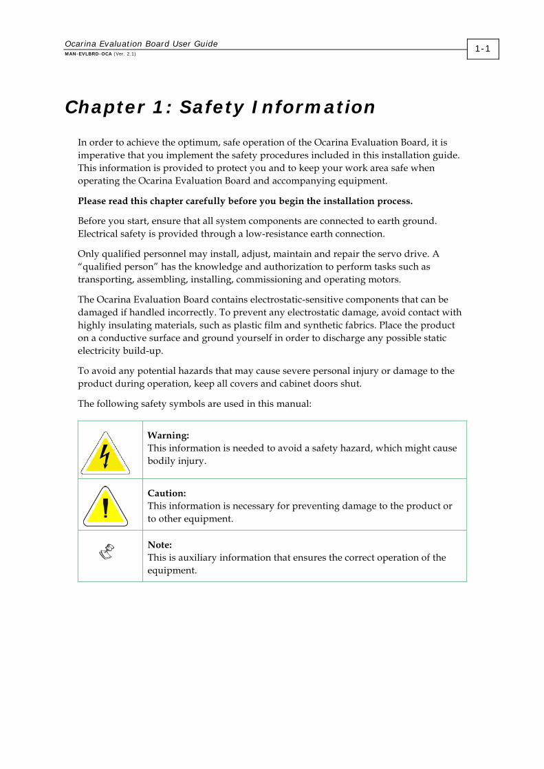
The following safety symbols are used in this manual:
Warning: This information is needed to avoid a safety hazard, which might cause bodily injury.
Caution: This information is necessary for preventing damage to the product or to other equipment.
Note: This is auxiliary information that ensures the correct operation of the equipment.
1-1
1.1 Warnings
To avoid electric arcing and hazards to personnel and electrical contacts, never connect/disconnect the servo drive while the power source is on.
Power cables can carry a high voltage, even when the motor is not in motion. Disconnect the Ocarina Evaluation Board from all voltage sources before it is opened for servicing.
The Ocarina Evaluation Board contains grounding conduits for electric current protection. Any disruption to these conduits may cause the instrument to become hot (live) and dangerous.
After shutting off the power and removing the power source from your equipment, wait at least 1 minute before touching or disconnecting parts of the equipment that are normally loaded with electrical charges (such as capacitors or contacts). Measuring the electrical contact points with a meter, before touching the equipment, is recommended.
1.2 Cautions
The Ocarina Evaluation Board contains hot surfaces and electrically-charged components during operation.
The maximum DC power supply connected to the instrument must comply with the parameters outlined in this guide. Furthermore, the power supply must be isolated from hazardous live voltages using reinforced or double insulation in accordance to approved safety standards.
When connecting the Ocarina Evaluation Board to an approved 12 ~ 95V DC auxiliary power supply, connect it through a line that is isolated from hazardous live voltages using reinforced or double insulation in accordance with approved safety standards.
Before switching on the Ocarina Evaluation Board, verify that all safety precautions have been observed and that the installation procedures in this manual have been followed.
Ocarina Evaluation Board User Guide Safety Information MAN-EVLBRD-OCA (Ver. 2.1)
1-2
1.3 Directives and Standards
The Ocarina Evaluation Board conforms to the following industry safety standards:
Safety Standard Item
In compliance with UL508c Power Conversion Equipment
In compliance with UL840 Insulation Coordination, Including Clearance and Creepage Distances of Electrical Equipment
In compliance with UL60950-1 (formerly UL1950)
Safety of Information Technology Equipment, Including Electrical Business Equipment
In compliance with EN60204-1 Low Voltage Directive, 73/23/EEC
The Ocarina Evaluation Board has been developed, produced, tested and documented in accordance with the relevant standards. Elmo Motion Control is not responsible for any deviation from the configuration and installation described in this documentation. Furthermore, Elmo is not responsible for the performance of new measurements or ensuring that regulatory requirements are met.
1.4 CE Mark Conformance
The Ocarina Evaluation Board is intended for incorporation in a machine or end product. The actual end product must comply with all safety aspects of the relevant requirements of the European Safety of Machinery Directive 98/37/EC as amended, and with those of the most recent versions of standards EN60204-1 and EN292-2 at the least.
According to Annex III of Article 13 of Council Directive 93/68/EEC, amending Council Directive 73/23/EEC concerning electrical equipment designed for use within certain voltage limits, the Ocarina Evaluation Board meets the provisions outlined in Council Directive 73/23/EEC. The party responsible for ensuring that the equipment meet the limits required by EMC regulations is the manufacturer of the end product.
1.5 Warranty Information
The products covered in this manual are warranted to be free of defects in material and workmanship and conform to the specifications stated either within this document or in the product catalog description. All Elmo drives are warranted for a period of 12 months from the time of installation, or 18 months from time of shipment, whichever comes first. No other warranties, expressed or implied — and including a warranty of merchantability and fitness for a particular purpose — extend beyond this warranty.
Ocarina Evaluation Board User Guide Safety Information MAN-EVLBRD-OCA (Ver. 2.1)
1-3
Ocarina Evaluation Board User Guide Safety Information MAN-EVLBRD-OCA (Ver. 2.1)
1-4
1.6 Before You Begin
1.6.1 Site Requirements
You can guarantee the safe operation of the Ocarina Evaluation Board by ensuring that it operates in an appropriate environment.
Feature Value
Ambient operating temperature 0° to 40°C (32° to 104°F)
Maximum relative humidity 90% non-condensing
Operating area atmosphere No flammable gases or vapors permitted in area
The Ocarina on the Ocarina Evaluation Board dissipates its heat by convection. The maximum operating ambient temperature of 0 to 40° C (32 to 104° F) must not be exceeded. Refer to the Heat Dissipation section of the Ocarina Installation Guide for more information.
Ocarina Evaluation Board User Guide MAN-EVLBRD-OCA (Ver. 2.2)
2-1
Chapter 2: Evaluation Board Connectors and Cables
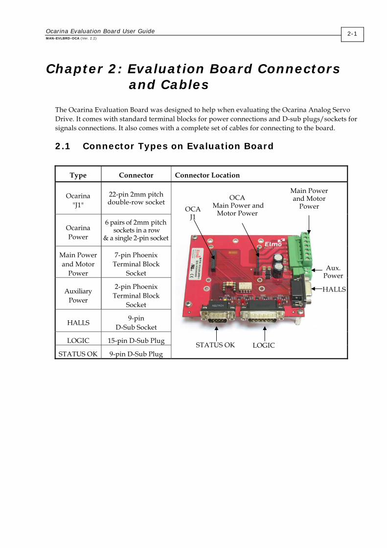
The Ocarina Evaluation Board was designed to help when evaluating the Ocarina Analog Servo Drive. It comes with standard terminal blocks for power connections and D-sub plugs/sockets for signals connections. It also comes with a complete set of cables for connecting to the board.
2.1 Connector Types on Evaluation Board
Type Connector Connector Location
Ocarina "J1"
22-pin 2mm pitch double-row socket
Ocarina Power
6 pairs of 2mm pitch sockets in a row
& a single 2-pin socket
Main Power and Motor
Power
7-pin Phoenix Terminal Block
Socket
Auxiliary Power
2-pin Phoenix Terminal Block
Socket
HALLS 9-pin D-Sub Socket
LOGIC 15-pin D-Sub Plug
STATUS OK 9-pin D-Sub Plug
Main Power and Motor
Power
Aux. Power
HALLS
OCA J1
OCA Main Power and
Motor Power
LOGIC STATUS OK
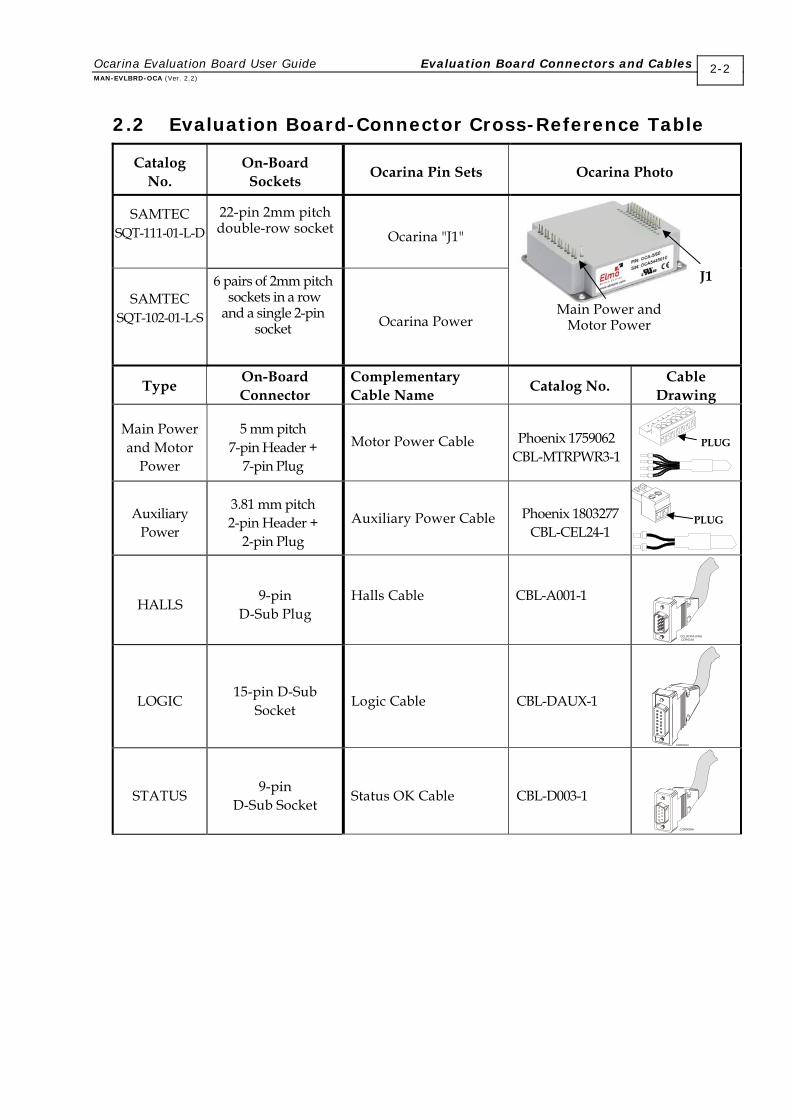
2.2 Evaluation Board-Connector Cross-Reference Table
Catalog No.
On-Board Sockets Ocarina Pin Sets Ocarina Photo
SAMTEC SQT-111-01-L-D
22-pin 2mm pitch double-row socket
Ocarina "J1"
SAMTEC SQT-102-01-L-S
6 pairs of 2mm pitch sockets in a row and a single 2-pin
socket
Ocarina Power
Type On-Board Connector
Complementary Cable Name Catalog No. Cable
Drawing
Main Power and Motor
Power
5 mm pitch 7-pin Header +
7-pin Plug
Motor Power Cable Phoenix 1759062
CBL-MTRPWR3-1 PLUG
Auxiliary Power
3.81 mm pitch 2-pin Header +
2-pin Plug
Auxiliary Power Cable Phoenix 1803277
CBL-CEL24-1 PLUG
HALLS 9-pin D-Sub Plug
Halls Cable
CBL-A001-1
CEL0040A-DWGCOR016A
LOGIC 15-pin D-Sub Socket Logic Cable CBL-DAUX-1
COR016A
STATUS 9-pin D-Sub Socket Status OK Cable CBL-D003-1
Main Power and Motor Power
J1
Ocarina Evaluation Board User Guide Evaluation Board Connectors and Cables MAN-EVLBRD-OCA (Ver. 2.2)
2-2
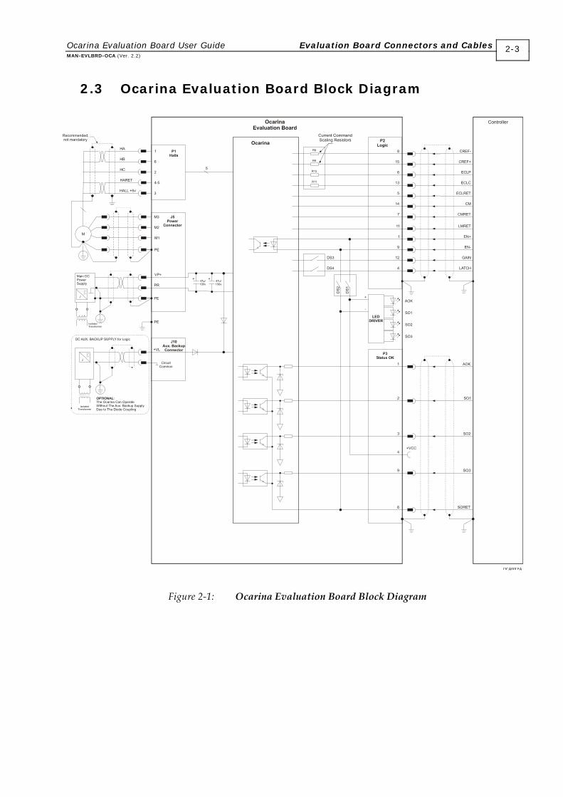
2.3 Ocarina Evaluation Board Block Diagram
Figure 2-1: Ocarina Evaluation Board Block Diagram
Ocarina Evaluation Board User Guide Evaluation Board Connectors and Cables MAN-EVLBRD-OCA (Ver. 2.2)
2-3
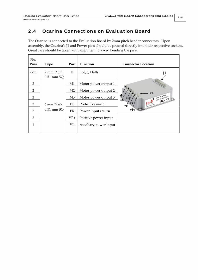
2.4 Ocarina Connections on Evaluation Board
The Ocarina is connected to the Evaluation Board by 2mm pitch header connectors. Upon assembly, the Ocarina's J1 and Power pins should be pressed directly into their respective sockets. Great care should be taken with alignment to avoid bending the pins.
No. Pins
Type
Port
Function Connector Location
2x11 2 mm Pitch 0.51 mm SQ
J1 Logic, Halls
2 M1 Motor power output 1
2 M2 Motor power output 2
2 M3 Motor power output 3
2 PE Protective earth
2 PR Power input return
2 VP+ Positive power input
1
2 mm Pitch 0.51 mm SQ
VL Auxiliary power input
J1
M3
M2 M1
PR PE
VL
VP+
Ocarina Evaluation Board User Guide Evaluation Board Connectors and Cables MAN-EVLBRD-OCA (Ver. 2.2)
2-4
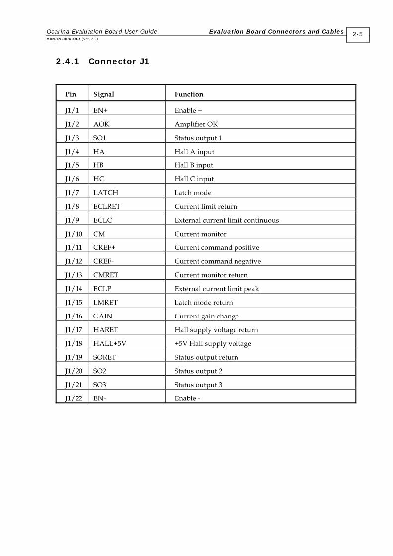
2.4.1 Connector J1
Pin Signal Function
J1/1 EN+ Enable +
J1/2 AOK Amplifier OK
J1/3 SO1 Status output 1
J1/4 HA Hall A input
J1/5 HB Hall B input
J1/6 HC Hall C input
J1/7 LATCH Latch mode
J1/8 ECLRET Current limit return
J1/9 ECLC External current limit continuous
J1/10 CM Current monitor
J1/11 CREF+ Current command positive
J1/12 CREF- Current command negative
J1/13 CMRET Current monitor return
J1/14 ECLP External current limit peak
J1/15 LMRET Latch mode return
J1/16 GAIN Current gain change
J1/17 HARET Hall supply voltage return
J1/18 HALL+5V +5V Hall supply voltage
J1/19 SORET Status output return
J1/20 SO2 Status output 2
J1/21 SO3 Status output 3
J1/22 EN- Enable -
Ocarina Evaluation Board User Guide Evaluation Board Connectors and Cables MAN-EVLBRD-OCA (Ver. 2.2)
2-5
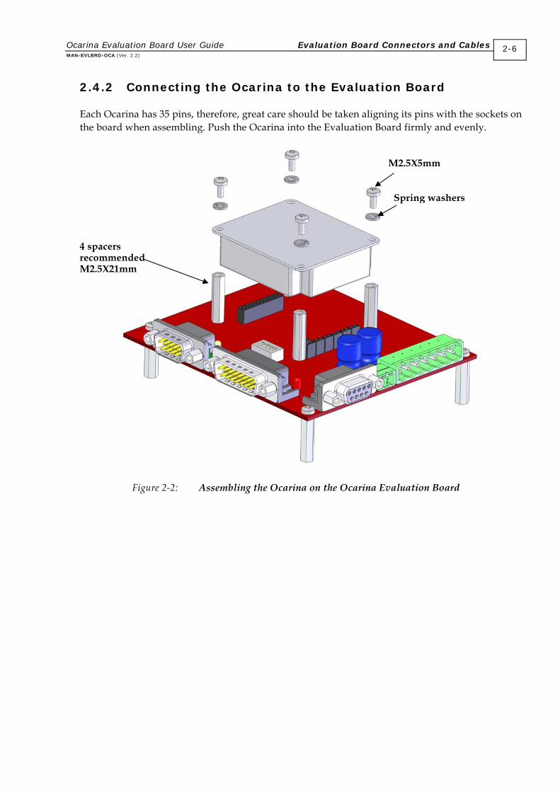
2.4.2 Connecting the Ocarina to the Evaluation Board
Each Ocarina has 35 pins, therefore, great care should be taken aligning its pins with the sockets on the board when assembling. Push the Ocarina into the Evaluation Board firmly and evenly.
Figure 2-2: Assembling the Ocarina on the Ocarina Evaluation Board
M2.5X5mm
Spring washers
4 spacers recommendedM2.5X21mm
Ocarina Evaluation Board User Guide Evaluation Board Connectors and Cables MAN-EVLBRD-OCA (Ver. 2.2)
2-6
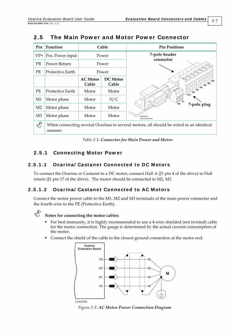
2.5 The Main Power and Motor Power Connector
Pin Function Cable Pin Positions
VP+ Pos. Power input Power
PR Power Return Power
PE Protective Earth Power AC Motor
Cable DC Motor
Cable PE Protective Earth Motor Motor
M1 Motor phase Motor N/C
M2 Motor phase Motor Motor
M3 Motor phase Motor Motor
When connecting several Ocarinas to several motors, all should be wired in an identical manner.
Table 2-1: Connector for Main Power and Motor
2.5.1 Connecting Motor Power
2.5.1.1 Ocarina/Castanet Connected to DC Motors
To connect the Ocarina or Castanet to a DC motor, connect Hall A (J1 pin 4 of the drive) to Hall return (J1 pin 17 of the drive). The motor should be connected to M2, M3.
2.5.1.2 Ocarina/Castanet Connected to AC Motors
Connect the motor power cable to the M1, M2 and M3 terminals of the main power connector and the fourth wire to the PE (Protective Earth).
Notes for connecting the motor cables: For best immunity, it is highly recommended to use a 4-wire shielded (not twisted) cable
for the motor connection. The gauge is determined by the actual current consumption of the motor.
Connect the shield of the cable to the closest ground connection at the motor end.
Figure 2-3: AC Motor Power Connection Diagram
7-pole header connector
7-pole plug
Ocarina Evaluation Board User Guide Evaluation Board Connectors and Cables MAN-EVLBRD-OCA (Ver. 2.2)
2-7
Ocarina Evaluation Board User Guide Evaluation Board Connectors and Cables MAN-EVLBRD-OCA (Ver. 2.2)
2-8
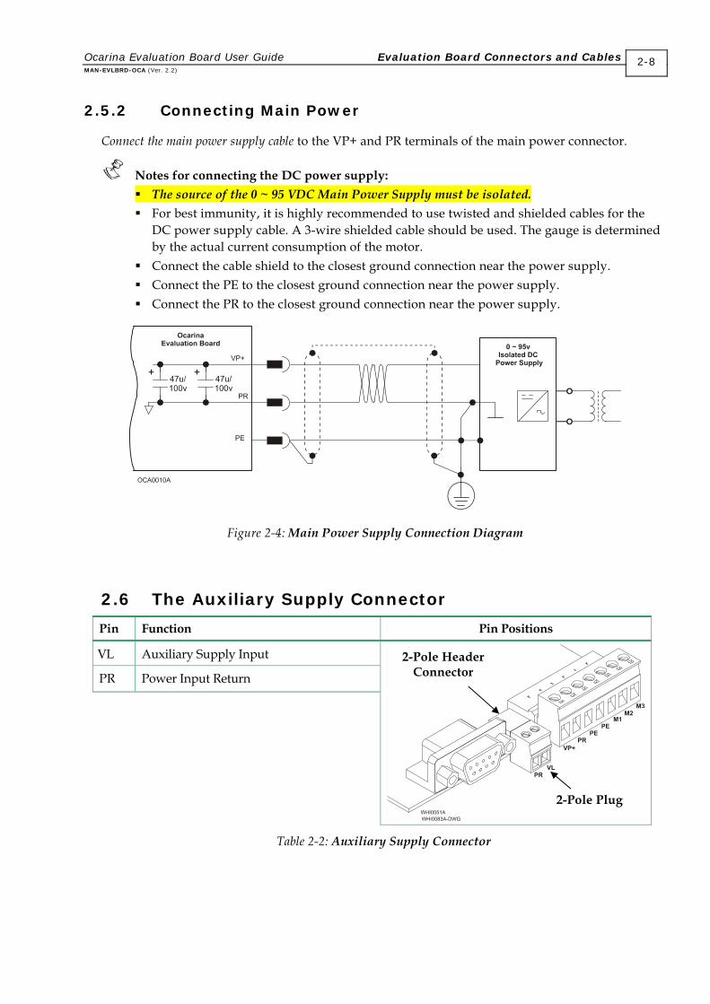
2.5.2 Connecting Main Power
Connect the main power supply cable to the VP+ and PR terminals of the main power connector.
Notes for connecting the DC power supply: The source of the 0 ~ 95 VDC Main Power Supply must be isolated. For best immunity, it is highly recommended to use twisted and shielded cables for the
DC power supply cable. A 3-wire shielded cable should be used. The gauge is determined by the actual current consumption of the motor.
Connect the cable shield to the closest ground connection near the power supply. Connect the PE to the closest ground connection near the power supply. Connect the PR to the closest ground connection near the power supply.
Figure 2-4: Main Power Supply Connection Diagram
2.6 The Auxiliary Supply Connector
Pin Function Pin Positions
VL Auxiliary Supply Input
PR Power Input Return
2-Pole Header Connector
2-Pole Plug
Table 2-2: Auxiliary Supply Connector
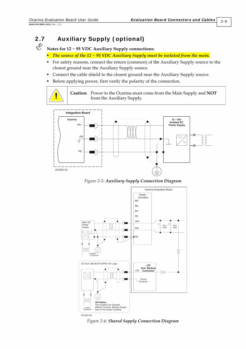
2.7 Auxiliary Supply (optional)
Notes for 12 ~ 95 VDC Auxiliary Supply connections: The source of the 12 ~ 95 VDC Auxiliary Supply must be isolated from the main. For safety reasons, connect the return (common) of the Auxiliary Supply source to the
closest ground near the Auxiliary Supply source. Connect the cable shield to the closest ground near the Auxiliary Supply source. Before applying power, first verify the polarity of the connection.
Caution: Power to the Ocarina must come from the Main Supply and NOT from the Auxiliary Supply.
Figure 2-5: Auxiliary Supply Connection Diagram
Figure 2-6: Shared Supply Connection Diagram
Ocarina Evaluation Board User Guide Evaluation Board Connectors and Cables MAN-EVLBRD-OCA (Ver. 2.2)
2-9
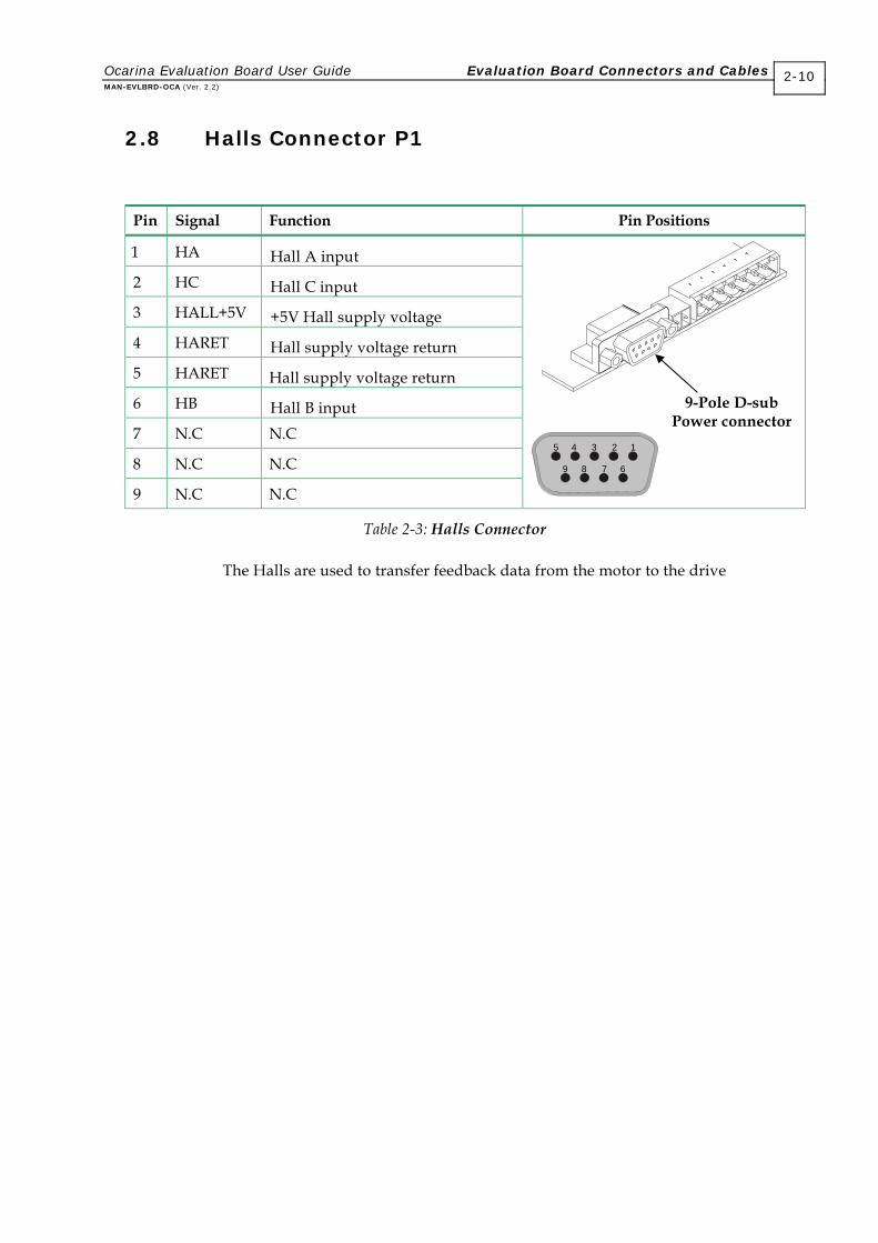
2.8 Halls Connector P1
Pin Signal Function Pin Positions
1 HA Hall A input 2 HC Hall C input 3 HALL+5V +5V Hall supply voltage 4 HARET Hall supply voltage return 5 HARET Hall supply voltage return 6 HB Hall B input 7 N.C N.C
8 N.C N.C
9 N.C N.C
12345
6789
Table 2-3: Halls Connector
The Halls are used to transfer feedback data from the motor to the drive
9-Pole D-sub Power connector
Ocarina Evaluation Board User Guide Evaluation Board Connectors and Cables MAN-EVLBRD-OCA (Ver. 2.2)
2-10
2.9 Logic Connector P2
Current command scaling resistors (R8 and R9 of the orcad design) The user can change the default scale of the differential input (±3.75) by calculating and inserting R8 and R9 into the designated solderless terminals. The value of these resistors are given by:
R8=R9=5.33XVcref-20
Vcref is the desired maximum reference voltage. If for example, the new desired scale is ±10V, all that is required is to change the default resistors (0Ω) to 33KΩ.
External current limit-continuous (ECLC) Refer to section 4.2.2 in the “Ocarina Installation Guide” A solderless terminal is available for RECLC. It is designated as R11 of the orcad design.
External current limit-peak (ECLP) Refer to section 4.2.3 in the “Ocarina Installation Guide” A solderless terminal is available for RECLP. It is designated as R12 of the orcad design.
Latch mode By setting S4 to the “ON” position, whenever one of the following failures: Short, Commutation failure and Over Temperature occur, the amplifier will be latched in disable mode. Disabling the amplifier (removing and reconnecting the power from the enable pins J1/1 and J1/22) resets the latch.
Enable Pins J1/1 and J1/22 are the inputs of an opto-coupler. The opto-coupler must be energized to enable operation of the amplifier. If the enable input is kept high before powering the amplifier, the amplifier power output will be active immediately upon power on. To enable the operation of the amplifier, the opto-coupler must be “ON”, This can be done in two ways:
1. Apply voltage between P2/1 (EN+) and P2/9 (EN-). Minimum “ON” voltage: 5V, current consumption 1.2mA.
Maximum “ON” voltage: 15V, current consumption 5mA. 2. Set Dip switches 1 and 2 to the “ON” position. Apply voltage between P3/4 (+VCC) and P3/6 (SORET) (eliminate the need for connecting voltage between P2/1 (EN+) and P2/9 (EN-). Minimum “ON” voltage: 5V, current consumption 1.2mA. Maximum “ON” voltage: 10V, current consumption 5mA. Note: For disabling the amplifier set DS1 or DS2 to “OFF”.
Ocarina Evaluation Board User Guide Evaluation Board Connectors and Cables MAN-EVLBRD-OCA (Ver. 2.2)
2-11

2.10 Status OK Connector P3
Pin Function Remarks
1 AOK Refer to section 3.6.2 in the “Ocarina Installation Guide”
2 SO1 Refer to section 3.6.2 in the “Ocarina Installation Guide”
3 SO2 Refer to section 3.6.2 in the “Ocarina Installation Guide”
4 +VCC Through this interface, the user can activate and use the “on-board” LED-Display, by applying a power source between P3/4 and P3/6. The user can use this supply also for enabling the amplifier (eliminating the need in connecting another supply between P2/1 and P2/9).
This can be achieved by setting DS1 and DS2 to the “ON” position.
+VCC min. Voltage = 5 V
+VCC max. Voltage = 15 V
+VCC max. Current = 35 ma 6 SORET Return for +VCC 9 SO3 Refer to section 3.6.2 in the “Ocarina Installation Guide”
2.11 DIP Switch Table
Switches Function ON OFF
S1 EN+ Applicable for enabling the amplifier only when the user already applied +VCC and SORET for LED-Display
Disabling the amplifier when using +VCC and SORET also for EN purposes
S2 EN- Applicable for enabling the amplifier only when the user already applied +VCC and SORET for LED-Display
Disabling the amplifier when using +VCC and SORET also for EN purposes
S3 GAIN Changing S3 to the "ON" position reduces the proportional gain (P) of the current loop by 70%
GAIN-OFF
S4 LATCH Latch mode Non-latch mode
Table 2-4: Dip Switch Table
Ocarina Evaluation Board User Guide Evaluation Board Connectors and Cables MAN-EVLBRD-OCA (Ver. 2.2)
2-12
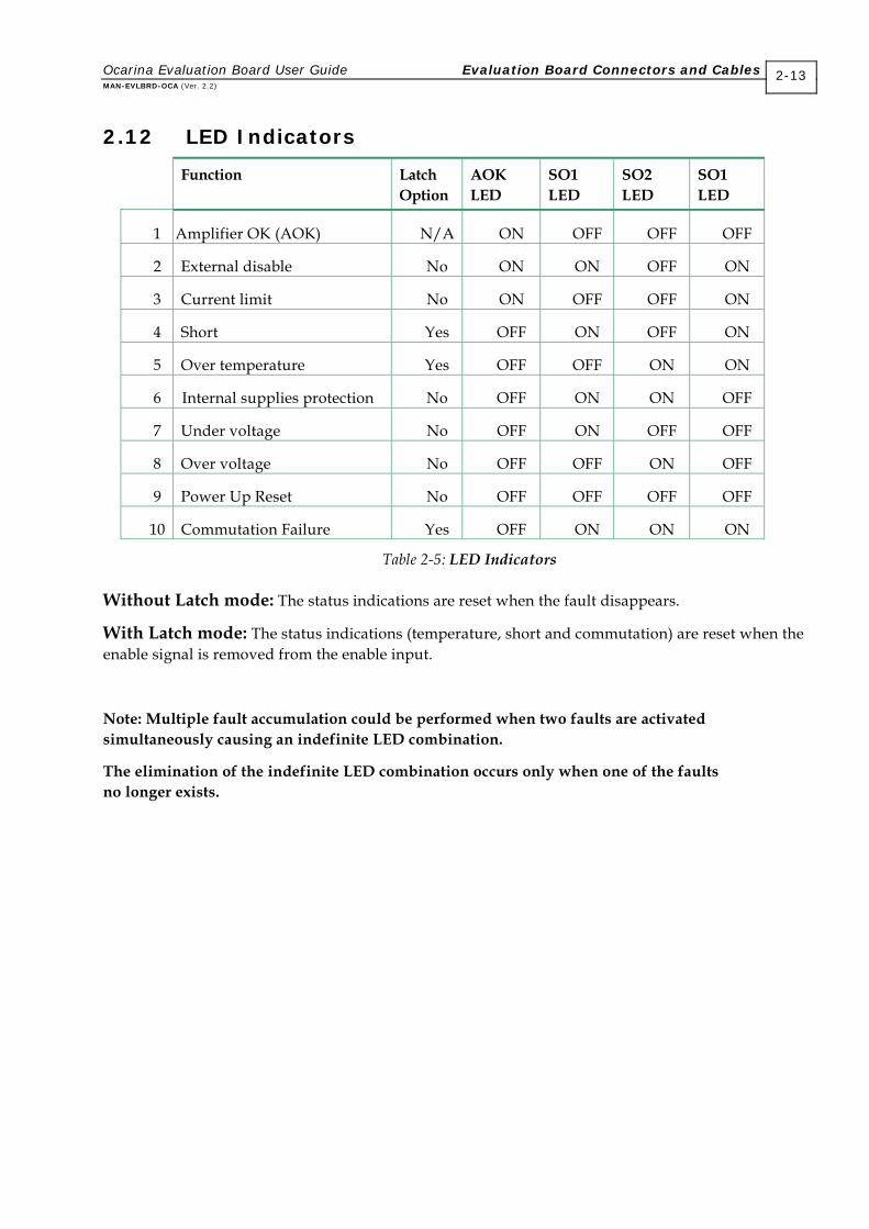
2.12 LED Indicators
Function Latch Option
AOK LED
SO1 LED
SO2 LED
SO1 LED
1 Amplifier OK (AOK) N/A ON OFF OFF OFF
2 External disable No ON ON OFF ON
3 Current limit No ON OFF OFF ON
4 Short Yes OFF ON OFF ON
5 Over temperature Yes OFF OFF ON ON
6 Internal supplies protection No OFF ON ON OFF
7 Under voltage No OFF ON OFF OFF
8 Over voltage No OFF OFF ON OFF
9 Power Up Reset No OFF OFF OFF OFF
10 Commutation Failure Yes OFF ON ON ON
Table 2-5: LED Indicators
Without Latch mode: The status indications are reset when the fault disappears.
With Latch mode: The status indications (temperature, short and commutation) are reset when the enable signal is removed from the enable input.
Note: Multiple fault accumulation could be performed when two faults are activated simultaneously causing an indefinite LED combination.
The elimination of the indefinite LED combination occurs only when one of the faults no longer exists.
Ocarina Evaluation Board User Guide Evaluation Board Connectors and Cables MAN-EVLBRD-OCA (Ver. 2.2)
2-13
2.13 Powering Up
After the Ocarina is mounted on the Ocarina Evaluation Board and the cables have been connected to their devices, the Ocarina Evaluation Board is ready to be powered up.
Caution: Before applying power, ensure that the DC supply is within the specified range and that the proper plus-minus connections are in order.
2.14 Initializing the System
After the Ocarina Evaluation Board has been connected and mounted, the system must be set up and initialized.
Ocarina Evaluation Board User Guide Evaluation Board Connectors and Cables MAN-EVLBRD-OCA (Ver. 2.2)
2-14
Ocarina Evaluation Board User Guide MAN-EVLBRD-OCA (Ver. 2.1)
A-1
Appendix: Cables
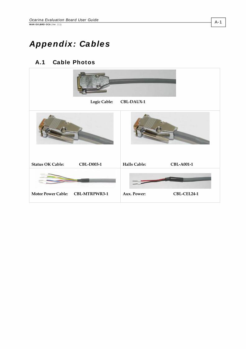
A.1 Cable Photos
Logic Cable: CBL-DAUX-1
Status OK Cable: CBL-D003-1
Halls Cable: CBL-A001-1
Motor Power Cable: CBL-MTRPWR3-1
Aux. Power: CBL-CEL24-1

A.2 Cable Kits
A full set of cables is supplied with the Evaluation Board. The cables are all 1m in length. Each set contains the cables listed below. Additional cable kits and individual cables (individually or in multiples of 10 each) are available from Elmo.
Cable Application Cable Part. No.
Logic CBL-DAUX-1
Halls CBL-A001-1
Status OK CBL-D003-1
Motor Power CBL-MTRPWR3-1
Auxiliary Power CBL-CEL24-1
Ocarina Evaluation Board User Guide Cables MAN-EVLBRD-OCA (Ver. 2.1)
A-2
Ocarina Evaluation Board User Guide Cables MAN-EVLBRD-OCA (Ver. 2.1)
A-3
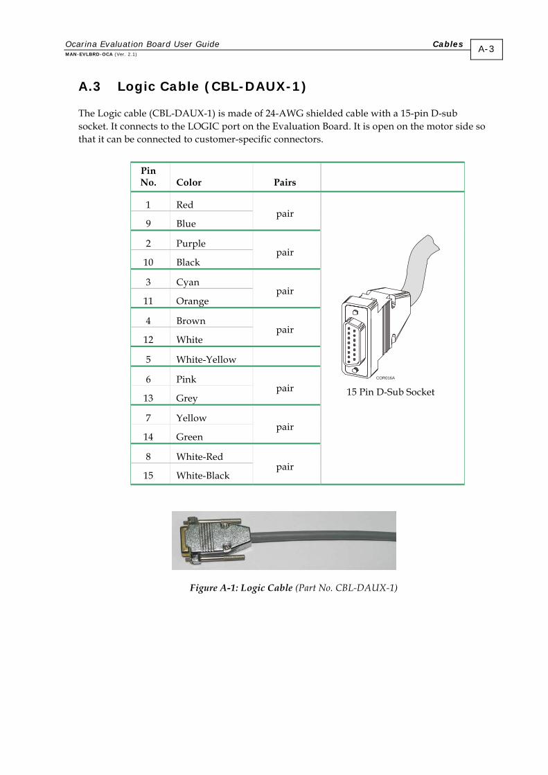
A.3 Logic Cable (CBL-DAUX-1)
The Logic cable (CBL-DAUX-1) is made of 24-AWG shielded cable with a 15-pin D-sub socket. It connects to the LOGIC port on the Evaluation Board. It is open on the motor side so that it can be connected to customer-specific connectors.
Pin No. Color Pairs
1 Red
9 Blue pair
2 Purple
10 Black pair
3 Cyan
11 Orange pair
4 Brown
12 White pair
5 White-Yellow
6 Pink
13 Grey pair
7 Yellow
14 Green pair
8 White-Red
15 White-Black pair
COR016A 15 Pin D-Sub Socket
Figure A-1: Logic Cable (Part No. CBL-DAUX-1)
Ocarina Evaluation Board User Guide Cables MAN-EVLBRD-OCA (Ver. 2.1)
A-4
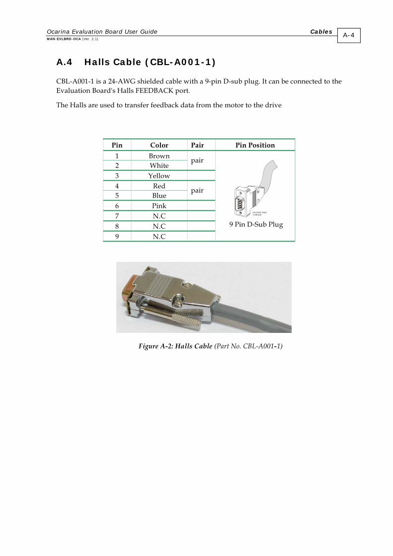
A.4 Halls Cable (CBL-A001-1)
CBL-A001-1 is a 24-AWG shielded cable with a 9-pin D-sub plug. It can be connected to the Evaluation Board's Halls FEEDBACK port.
The Halls are used to transfer feedback data from the motor to the drive
Pin Color Pair Pin Position
1 Brown 2 White
pair
3 Yellow 4 Red 5 Blue
pair
6 Pink 7 N.C 8 N.C 9 N.C
CEL0040A-DWGCOR016A
9 Pin D-Sub Plug
Figure A-2: Halls Cable (Part No. CBL-A001-1)
Ocarina Evaluation Board User Guide Cables MAN-EVLBRD-OCA (Ver. 2.1)
A-5
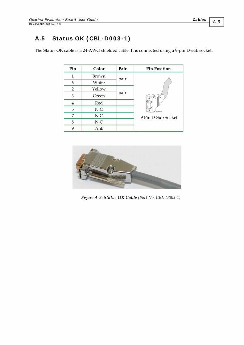
A.5 Status OK (CBL-D003-1)
The Status OK cable is a 24-AWG shielded cable. It is connected using a 9-pin D-sub socket.
Pin Color Pair Pin Position
1 Brown 6 White
pair
2 Yellow 3 Green
pair
4 Red 5 N.C 7 N.C 8 N.C 9 Pink
9 Pin D-Sub Socket
Figure A-3: Status OK Cable (Part No. CBL-D003-1)
Ocarina Evaluation Board User Guide Cables MAN-EVLBRD-OCA (Ver. 2.1)
A-6
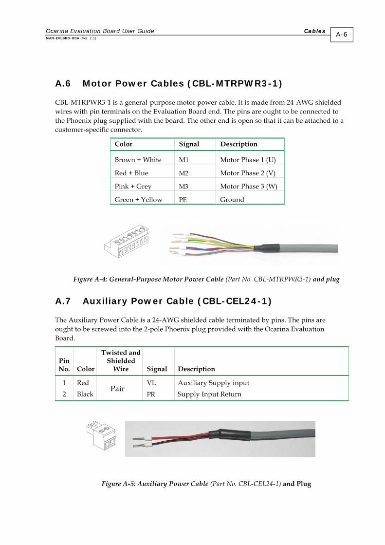
A.6 Motor Power Cables (CBL-MTRPWR3-1)
CBL-MTRPWR3-1 is a general-purpose motor power cable. It is made from 24-AWG shielded wires with pin terminals on the Evaluation Board end. The pins are ought to be connected to the Phoenix plug supplied with the board. The other end is open so that it can be attached to a customer-specific connector.
Color Signal Description
Brown + White M1 Motor Phase 1 (U)
Red + Blue M2 Motor Phase 2 (V)
Pink + Grey M3 Motor Phase 3 (W)
Green + Yellow PE Ground
Figure A-4: General-Purpose Motor Power Cable (Part No. CBL-MTRPWR3-1) and plug
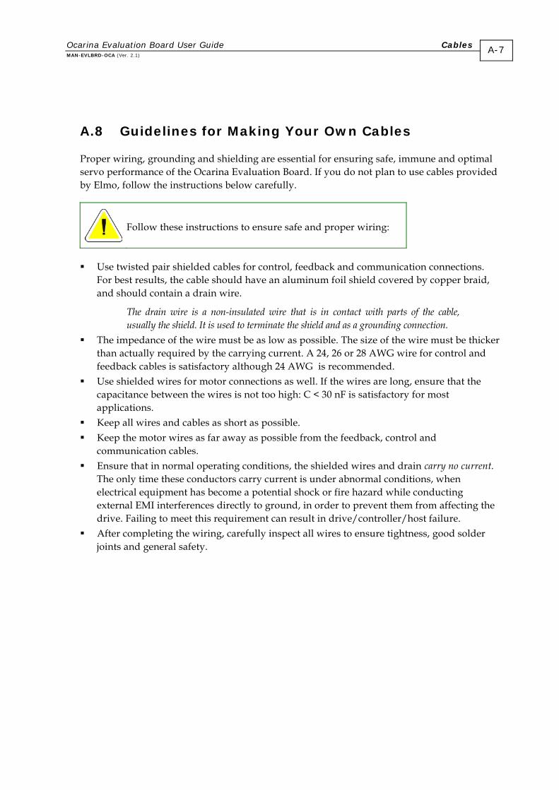
A.7 Auxiliary Power Cable (CBL-CEL24-1)
The Auxiliary Power Cable is a 24-AWG shielded cable terminated by pins. The pins are ought to be screwed into the 2-pole Phoenix plug provided with the Ocarina Evaluation Board.
Pin No.
Color
Twisted and Shielded
Wire
Signal
Description
1 Red VL Auxiliary Supply input 2 Black
Pair PR Supply Input Return
Figure A-5: Auxiliary Power Cable (Part No. CBL-CEL24-1) and Plug
A.8 Guidelines for Making Your Own Cables
If you do not plan to use cables provided by Elmo, follow the instructions below carefully.
Proper wiring, grounding and shielding are essential for ensuring safe, immune and optimal servo performance of the Ocarina Evaluation Board.
Follow these instructions to ensure safe and proper wiring:
Use twisted pair shielded cables for control, feedback and communication connections. For best results, the cable should have an aluminum foil shield covered by copper braid, and sh
e,
er ire for control and
at the tween the wires is not too high: C < 30 nF is satisfactory for most
far away as possible from the feedback, control and
rrent.
ng the
g, carefully inspect all wires to ensure tightness, good solder joints and general safety.
Ocarina Evaluation Board User Guide Cables MAN-EVLBRD-OCA (Ver. 2.1)
ould contain a drain wire.
The drain wire is a non-insulated wire that is in contact with parts of the cabl
A-7
usually the shield. It is used to terminate the shield and as a grounding connection. The impedance of the wire must be as low as possible. The size of the wire must be thick
than actually required by the carrying current. A 24, 26 or 28 AWG wfeedback cables is satisfactory although 24 AWG is recommended.
Use shielded wires for motor connections as well. If the wires are long, ensure thcapacitance beapplications.
Keep all wires and cables as short as possible. Keep the motor wires as
communication cables. Ensure that in normal operating conditions, the shielded wires and drain carry no cu
The only time these conductors carry current is under abnormal conditions, when electrical equipment has become a potential shock or fire hazard while conducting external EMI interferences directly to ground, in order to prevent them from affectidrive. Failing to meet this requirement can result in drive/controller/host failure.
After completing the wirin
A.8.1 Recommended Wire Cross Sections
Function Connection Details
Motor PE, M1, M2, M3 24 AWG
Auxiliary power VL, PR 24 AWG
Feedback and Control HALLS
LOGIC
STATUS OK
24 AWG twisted pair shielded cables as described below (Section A.8.4)
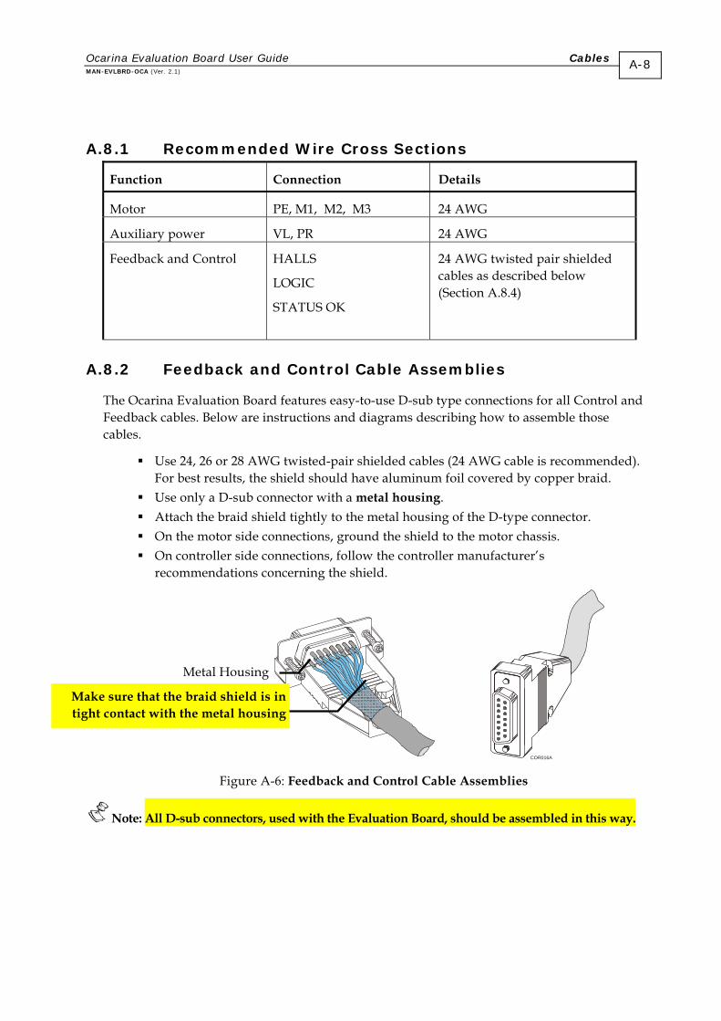
A.8.2 Feedback and Control Cable Assemblies
The Ocarina Evaluation Board features easy-to-use D-sub type connections for all Control and Feedback cables. Below are instructions and diagrams describing how to assemble those cables.
Use 24, 26 or 28 AWG twisted-pair shielded cables (24 AWG cable is recommended). For best results, the shield should have aluminum foil covered by copper braid.
Use only a D-sub connector with a metal housing. Attach the braid shield tightly to the metal housing of the D-type connector. On the motor side connections, ground the shield to the motor chassis. On controller side connections, follow the controller manufacturer’s
recommendations concerning the shield.
COR016A
Figure A-6: Feedback and Control Cable Assemblies
Note: All D-sub connectors, used with the Evaluation Board, should be assembled in this way.
Metal Housing
Make sure that the braid shield is in tight contact with the metal housing
Ocarina Evaluation Board User Guide Cables MAN-EVLBRD-OCA (Ver. 2.1)
A-8
Ocarina Evaluation Board User Guide Cables MAN-EVLBRD-OCA (Ver. 2.1)
A-9
A.8.3 Recommended Wire Cross Sections
Function Connection Details
Motor PE, M1, M2, M3 24 AWG
Auxiliary power VL, PR 24 AWG
Feedback and Control MAIN FEEDBACK
AUX FEEDBACK
GENERAL I/O
MAIN BUFFERED OUTPUT
24 AWG twisted pair shielded cables as described below (Section A.8.4)
Communications RS-232
CANopen
26 AWG twisted pair shielded cables as described below (Section A.8.4)
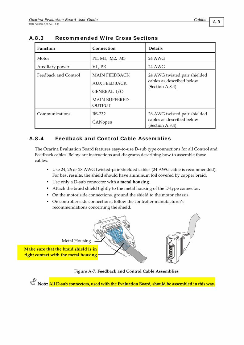
A.8.4 Feedback and Control Cable Assemblies
The Ocarina Evaluation Board features easy-to-use D-sub type connections for all Control and Feedback cables. Below are instructions and diagrams describing how to assemble those cables.
Use 24, 26 or 28 AWG twisted-pair shielded cables (24 AWG cable is recommended). For best results, the shield should have aluminum foil covered by copper braid.
Use only a D-sub connector with a metal housing. Attach the braid shield tightly to the metal housing of the D-type connector. On the motor side connections, ground the shield to the motor chassis. On controller side connections, follow the controller manufacturer’s
recommendations concerning the shield.
Figure A-7: Feedback and Control Cable Assemblies
Note: All D-sub connectors, used with the Evaluation Board, should be assembled in this way.
Metal Housing
Make sure that the braid shield is in tight contact with the metal housing