Embed Size (px)
Citation preview

OC950 Installation and Hardware Reference Manual
Document Part # MA950 Rev G
The Only Factory Authorized Repair Center for Pacific Scientific Servo & Stepper Drives
Motor Systems Inc.
460 Milford Parkway
Milford, OH . 45150
www.motorsystems.com
513-576-1725
Revision History Issue Date Brief Description G 06/04 Update corporate identity and contact information
Copyright Information © 1996 - 2004 Danaher Motion – All rights reserved. Printed in the United States of America.
DANAHER MOTION is a registered trademark of Danaher Corporation. Danaher Motion makes every attempt to ensure accuracy and reliability of the specifications in this publication. Specifications are subject to change without notice. Danaher Motion provides this information "AS IS" and disclaims all warranties, express or implied, including, but not limited to, implied warranties of merchantability and fitness for a particular purpose. It is the responsibility of the product user to determine the suitability of this product for a specific application. Danaher Motion reserves the right to make engineering refinements on all its products. Such refinements may affect information in instructions. USE ONLY THE INSTRUCTIONS PACKED WITH THE PRODUCT.
Safety-alert symbols used in this document are:
WARNING
Alerts you to potential physical danger or harm. Failure to follow warning notices could result in personal injury or death.
CAUTION
Directs attention to general precautions, which if not followed, could result in personal injury and/or equipment damage.
NOTE
Highlights information critical to your understanding or use of the product.

Danaher Motion Pacific Scientific 06/04 Table of Contents
MA950 Rev. G i
Table of Contents 1. OVERVIEW....................................................................................................................1
1. 1 OC950 PROGRAMMABLE OPTION CARD DEFINITION .................................................11.1.1. OC950 HARDWARE VARIETIES ................................................................1
1.1.1.1. STANDARD VERSION................................................................21.1.1.2. ENHANCED VERSION ...............................................................2
2. INSTALLATION AND SETUP.......................................................................................3
2. 1 HARDWARE SETUP ..................................................................................................32. 2 CONNECTIONS.........................................................................................................3
2.2.1. CONNECTION DIAGRAM............................................................................42. 3 SOFTWARE INSTALLATION ........................................................................................42. 4 USING 950IDE ........................................................................................................5
2.4.1. 950IDE MAIN MENU................................................................................52.4.2. MOVEMENT KEYS.....................................................................................5
2. 5 SYSTEM CONFIGURATION.........................................................................................62.5.1. APPLYING AC POWER .............................................................................62.5.2. SERIAL PORT ..........................................................................................62.5.3. CREATE A NEW PROGRAM .......................................................................72.5.4. WIZARDS.................................................................................................82.5.5. ENABLING DRIVE ...................................................................................102.5.6. COMPILING A PROGRAM.........................................................................102.5.7. RUN PROGRAM......................................................................................102.5.8. WORKING WITH BREAKPOINTS ...............................................................102.5.9. SETTING BREAKPOINTS..........................................................................112.5.10. REMOVING BREAKPOINTS ......................................................................112.5.11. CONTINUING PROGRAM EXECUTION .......................................................112.5.12. VARIABLES WINDOW..............................................................................12
2.5.12.1. MOTOR VELOCITY .................................................................122.5.12.2. MODIFYING VARIABLES..........................................................12
2.5.13. VIEWING VARIABLES ..............................................................................132.5.13.1. ADD VARIABLES TO A WATCH WINDOW: .................................132.5.13.2. REMOVE VARIABLES FROM A WATCH WINDOW .......................13
2.5.14. SAVING A PROGRAM ..............................................................................142.5.15. OPENING A PROGRAM............................................................................142.5.16. EXITING 950IDE....................................................................................14
3. OC950 INTERFACES AND CONNECTIONS .............................................................15
3. 1 CONNECTION DIAGRAM ..........................................................................................153. 2 SERIAL PORT J51 ..................................................................................................16
3.2.1. J51 SERIAL PORT T10 CONNECTIONS (RS-232) ....................................17

Table of Contents 06/04 Danaher Motion Pacific Scientific
ii Rev. G MA950
3.2.2. PARAMETER SETUP ...............................................................................17 3. 3 S1 SWITCH............................................................................................................18
3.3.1. S1 ADDRESS TABLE ..............................................................................19 3.3.2. OCIO + 5 VDC .....................................................................................20 3.3.3. RS-232 CONNECTIONS..........................................................................20
3.3.3.1. CABLING DIAGRAM ................................................................21 3.3.4. RS-485/RS-422 CONNECTIONS ............................................................21
3.3.4.1. RS-485/RS-422 DIAGRAM ....................................................21 3.3.4.2. OC950 SERIAL COMMUNICATIONS TRANSCEIVER SCHEMATIC 22
4. SERVO LOOP PARAMETERS ...................................................................................23 4. 1 VELOCITY LOOP .....................................................................................................23
4.1.1. VELOCITY LOOP BANDWIDTH..................................................................23 4.1.1.1. DEFAULT BANDWIDTHS ..........................................................24
4. 2 POSITION LOOP .....................................................................................................27 4. 3 ADVANCED VELOCITY LOOP TUNING .......................................................................29
5. TROUBLESHOOTING.................................................................................................31 5. 1 TROUBLESHOOTING ...............................................................................................31
5.1.1. SYSTEM STATUS....................................................................................31 5.1.2. EXTENDED FAULTCODES........................................................................32 5.1.3. TROUBLESHOOTING TABLE.....................................................................33 5.1.4. COMMUNICATIONS TROUBLESHOOTING TABLE ........................................37 5.1.5. CONTACT INFORMATION.........................................................................38
APPENDIX A SELECTING MOTOR CONTROL FUNCTIONALITY.....................................1 A.1 TORQUE BLOCK MODES ...........................................................................................1
A.1.1 ANALOG COMMAND TORQUE BLOCK (BLKTYPE = 0) .................................1 A.2.1 ANALOG COMMAND VELOCITY BLOCK (BLKTYPE = 1) ...............................3
A.3 POSITION BLOCK MODES .........................................................................................5 A.3.1 DIGITAL COMMAND POSITION BLOCK (BLKTYPE = 2) ................................5
APPENDIX B OC950 SPECIFICATIONS..............................................................................1 B.1 OC950 J51 SERIAL INTERFACE................................................................................1 B.2 OC950 J52 PROGRAMMABLE INPUTS / OUTPUTS .....................................................1 B.3 OUTPUT CHANNEL ...................................................................................................1 B.4 USER +5 V POWER..................................................................................................1 B.5 OC950 J53 (OPTIONAL) PACLAN............................................................................2 B.6 NVRAM - PROGRAM MEMORY.................................................................................2

Danaher Motion Pacific Scientific 06/04 OVERVIEW
MA950 Rev. G 1
1. OVERVIEW This section introduces the OC950 Programmable Option Card. Topics covered are: − OC950 Overview − How to Use this Manual − Warranty Information Installation and Setup is a step-by-step guide allowing you to configure an SC950 and run your motor within a few minutes. It is strongly recommended that you go through Installation and Setup first. This will give you a feel for using the SC950 and lay the framework for reading the other chapters. Thoroughly read OC950 Interfaces and Connections, Servo Loop Parameters, and Troubleshooting to gain the most from the OC950.
1. 1 OC950 PROGRAMMABLE OPTION CARD DEFINITION The OC950 is an option card that is installed in the option card slot of Danaher Motion's Pacific Scientific SC900 servo drive. Combined, the SC900 and OC950 create the SC950. It provides stand-alone, single-axis programmable positioning capability to a high performance, digital servo drive. The SC950 inherits all the advanced, high-performance functionality as well as the small package size of the SC900 platform. The SC950 also inherits all the hardware resources of that platform, including 6 points of bi-directional discrete I/O, two analog outputs, one analog input, one encoder input port and one encoder output port. The SC900 platform also provides two high-speed registration inputs. Resources provided on all varieties the OC950 include twenty-one points of bi-directional discrete I/O and an RS-232/RS-485 serial communications port. The OC950 provides for direct connection to Opto22 Industrial I/O mounting racks and industrial I/O modules with the use of the CA950-IO adapter module.
1.1.1. OC950 HARDWARE VARIETIES Two optional memory (NVRAM: nonvolatile random access memory) configurations are available, 32kx8 or 128kx8. NVRAM is battery backed, with a ten year life, and unlimited amount of write cycles. The memory provides storage for the user programs. A PacLAN™ network interface is offered as an OC950 option. PacLAN supports 2.5 MB/sec communications among a cluster of SC950 drives. The port is compatible with standard ArcNET products using 93 W coax cable in a bus configuration.

OVERVIEW 06/04 Danaher Motion Pacific Scientific
2 Rev. G MA950
1.1.1.1. Standard Version Combinations of the two memory offerings and the PacLAN option results in four standard versions of the OC950: OC950-501-01 Base 950 Option Card 32kx8 NVRAM
OC950-502-01 Base 950 Option Card 128kx8 NVRAM
OC950-503-01 Base 950 Option Card 32kx8 NVRAM + PacLAN
OC950-504-01 Base 950 Option Card 128kx8 NVRAM + PacLAN
1.1.1.2. Enhanced Version In addition, there is an Enhanced version of the OC950 which supports additional features, including MODBUS and camming. OC950-601-01 Enhanced 950 Option Card 32kx8 NVRAM OC950-602-01 Enhanced 950 Option Card 128kx8 NVRAM OC950-603-01 Enhanced 950 Option Card 32kx8 NVRAM + PacLAN OC950-604-01 Enhanced 950 Option Card 128kx8 NVRAM + PacLAN

Danaher Motion Pacific Scientific 06/04 Installation and Setup
2. INSTALLATION AND SETUP This section provides a step-by-step introduction to setting a system up to run the OC950 and the 950IDE PC interface software. This procedure uses the minimum possible equipment to run an unloaded motor and sets motor speed from a PC’s serial port. It is strongly recommended that all first time users go through this procedure to become familiar with the OC950 and the 950IDE PC interface software before installing the servo system in a machine.
2. 1 HARDWARE SETUP To go through this product introduction procedure you will need the following items: • SC900 Base Servo Drive • OC950 Programmable Option Card • Appropriate Brushless Motor with nothing attached to the shaft • PC Running Windows 3.1 or Windows95/NT • 950IDE Floppy Disk • Motor Power and Feedback Cables (J2, J3) • RS-232 Communications Cable (J51) • DB-25 Connector Mate (J4) • AC Power Line (J1)
If your OC950 is not already installed in your SC900, then use the following instructions to install it.
CAUTION
NEVER insert or remove an Option Card with the Control AC Power (J1-5, 6) active. Damage to the base SC900 or the Option Card could occur.
1. Remove Control AC Power from the SC900. The system status LED should be blank.
2. Loosen the two locking screws counterclockwise on the existing faceplate or existing Option Card and remove.
3. Position the new Option Card so that the silk screen reads the same as the base SC900.
4. Insert the Option Card by sliding it in all the way until it is flush with the base SC900.
5. Tighten the two locking screws by turning clockwise.
2. 2 CONNECTIONS Connect the motor, feedback, and AC Power cables as shown in the Connection Diagram but do not apply the AC power at this time. It is recommended that Danaher Motion motor and feedback cables be used during setup since improper cabling is the primary cause of start up problems.
MA950 Rev. G 3

Installation and Setup 06/04 Danaher Motion Pacific Scientific
Danaher Motion's RS-232 cable (part # CS-232-750) connects the 9-pin serial port socket on the OC950 to the PC. If this cable is unavailable, a simple 3-wire cable can be made using the wiring diagram shown on page 15. The last connection needed provides the hardware enable to the SC900 via J4-6 and I/O RTN on J4-5. Preferably, connect a toggle switch between J4-6 and J4-5. If a toggle switch is not available, use a clip lead that connects and disconnects J4-6 to J4-5.
2.2.1. CONNECTION DIAGRAM
2. 3 SOFTWARE INSTALLATION 1. Insert the 950IDE diskette in your disk drive (A: or B:). Start
Windows® and choose Run from the File menu of the Program Manager.
2. At the Command Line, type A:\setup950 or B:\setup950. 3. Either press the <Enter> key or click OK.
4 Rev. G MA950

Danaher Motion Pacific Scientific 06/04 Installation and Setup
4. Select the drive (default is C) and directory (default is \950Win) in which you want 950IDE installed.
5. Select a Program Manager Group (default is Pacific Scientific) in which to place the icons.
NOTE
When finished, remove the 950IDE disk from the drive and store it in a safe place.
2. 4 USING 950IDE To begin using 950IDE, if not already open, open the Pacific Scientific Group from the Program Manager. Double-click the 950 icon.
2.4.1. 950IDE MAIN MENU Once you double-click on the 950 icon, the Main Menu appears:
2.4.2. MOVEMENT KEYS 950IDE is a standard Windows application and the normal cursor movement keys operate the same way as in all windows applications. <F1> gives context sensitive on-line help
MA950 Rev. G 5

Installation and Setup 06/04 Danaher Motion Pacific Scientific
2. 5 SYSTEM CONFIGURATION
2.5.1. APPLYING AC POWER Carefully check all wiring connections and ensure that J4-6 is not connected to J4-5. Apply AC power to your controller. The drive status display LED should be alternately flashing U C (unconfigured) after the power up message.
2.5.2. SERIAL PORT To specify the PC serial port that is connected to the OC950: 1. Select Communications from the Options menu and the following
dialogue box appears:
2. Specify the serial port you want to use. 3. Specify the baud rate and click OK. 4. Select Variables from the Compile menu. 5. Type BaudRate in the Variable/expression box and press
<Enter>. 6. If the current value is incorrect, <Tab> to New Value and enter
the correct baud rate.
6 Rev. G MA950

Danaher Motion Pacific Scientific 06/04 Installation and Setup
2.5.3. CREATE A NEW PROGRAM Select New from the File menu and the following dialog box appears:
• Select the appropriate Motor Part Number from the dropdown
menu. • Select the Drive you’re using (Example: SC953). • Select Medium. • Select an inertia ratio. • Click OK. • Select a filename (*.BAS extension) for your new program. • Click OK, and the following window appears:
MA950 Rev. G 7
Installation and Setup 06/04 Danaher Motion Pacific Scientific
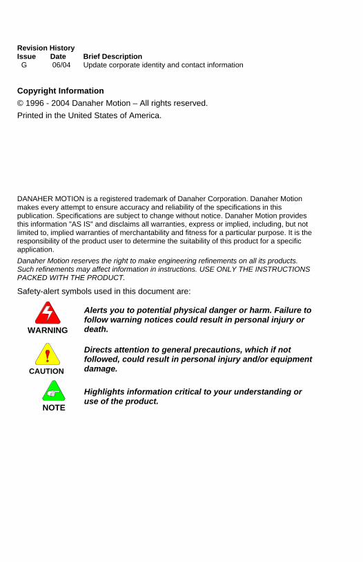
You can begin typing your program. To create a simple JOG move, type the following:
NOTE
The drive status display should show a steady 0 for configured and not enabled.
The current loop has been properly compensated for the selected motor, and the servo parameters have been set to a medium response (approximately 75 Hz velocity loop bandwidth) for the unloaded motor. Additional default settings have also been implemented.
NOTE
For additional tuning, click on the on-line tuning button in the toolbar and follow the on-line help.
Tuning Button
2.5.4. WIZARDS The following wizards in the 950IDE facilitate program creation: • Select Case • Modbus and A-B DF1 Map • Interrupt Handler • Move Command • Cam Setup
8 Rev. G MA950

Danaher Motion Pacific Scientific 06/04 Installation and Setup
To use a template to create a JOG move: 1. Select Move Command from the Wizards menu and the following
window appears:
2. Select the Velocity Move tab and enter the appropriate parameters.
3. Click OK. The text is inserted in the main program, below the cursor.
MA950 Rev. G 9
Installation and Setup 06/04 Danaher Motion Pacific Scientific
2.5.5. ENABLING DRIVE Enable the controller by closing the switch between the Enable input (J4-6) and I/O RTN (J4-5). The commanded motor speed is the power-up default (set to 0 during configuration).
WARNING
Before proceeding, the motor may need to be temporarily clamped down to prevent inertial forces from displacing the motor.
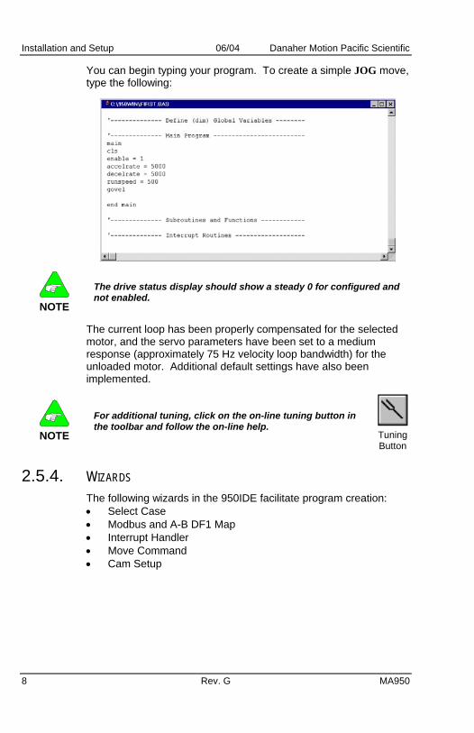
2.5.6. COMPILING A PROGRAM The SC950 requires a compiled program to be downloaded via serial communications. To compile a program: 1. Select Compile from the Compile menu. 2. Press <Ctrl> <F5> or click the Run icon.
Any error detected during compilation aborts further compilation (after the error is encountered), display the compilation status, and returns to the program, highlighting the program line containing the error.
3. Make necessary corrections until the program is successfully compiled and the Compiler Status indicates zero errors.
2.5.7. RUN PROGRAM Select Run from the Compile menu, press <F5> or click the Compile icon.
2.5.8. WORKING WITH BREAKPOINTS Breakpoints halt program execution at a specific location. 950IDE can set up to nine breakpoints within a program. Set breakpoints prior to running the program.
10 Rev. G MA950

Danaher Motion Pacific Scientific 06/04 Installation and Setup
2.5.9. SETTING BREAKPOINTS 1. Place the cursor on the line of code in which you want to set a
breakpoint. 2. Select Set Breakpoint from the Debug menu or press <F9>.
2.5.10. REMOVING BREAKPOINTS 1. Place the cursor on the line of code which contains a breakpoint
that you want to clear. 2. Select Clear Breakpoint from the Debug menu or press <F9>. 3. To remove all breakpoints in a program, select Clear All
Breakpoints from the Debug menu.
2.5.11. CONTINUING PROGRAM EXECUTION When a breakpoint is encountered during program execution, the SC950 suspends program execution and awaits further instruction. After a breakpoint is encountered, program execution can be continued by:
Selecting Continue from the Compile menu to continue program execution until the next breakpoint.
OR Selecting Single Step from the Debug menu.
OR Pressing <F8> to single step through the program line by line
OR Clicking on the Single Step icon.
MA950 Rev. G 11

Installation and Setup 06/04 Danaher Motion Pacific Scientific
2.5.12. VARIABLES WINDOW
2.5.12.1. Motor Velocity Select Variables in the Compile menu. The Variables window allows all parameters, variables, and commands to be examined, changed, or actuated as appropriate. Type the variable name in the Variable/Expression box. To examine the shaft velocity, type velcmd in the Variable/Expression box and press <Enter>. The present value of the motor velocity command in the drive is displayed under Current Value.
To continuously read and update the measured velocity, press Evaluate.
2.5.12.2. Modifying Variables To modify the value of the RUNSPEED, type RUNSPEED in the Variable/expression box and press <Enter>.The current value of RUNSPEED is displayed. To change the value, enter 1000 in the New Value box and click Modify.
12 Rev. G MA950

Danaher Motion Pacific Scientific 06/04 Installation and Setup
Type GOVEL in the Variable/Expression box and press <Enter>. The motor should run at the new speed.
2.5.13. VIEWING VARIABLES Use a Watch window to monitor multiple variables. Variables displayed in the Watch window are updated as breakpoints are encountered or after each single step. To open a Watch Window, select Watch Window from the Debug menu.
2.5.13.1. Add Variables to a Watch Window: You can add variables to the watch window while a program is not executing. 1. Select Variables from the Compile menu. 2. Type the name of the variable you which to watch in the
Variable/Expression box and click the Watch button. The Variable is added to the Watch window.
2.5.13.2. Remove Variables from a Watch Window You can remove any variable that has been added to the Watch window at any time. Select the variable in the Watch window and press <Delete>. To get help information on a particular key word, press <F1> while the cursor is located somewhere on that word in the Variable/Expression box.
MA950 Rev. G 13
Installation and Setup 06/04 Danaher Motion Pacific Scientific
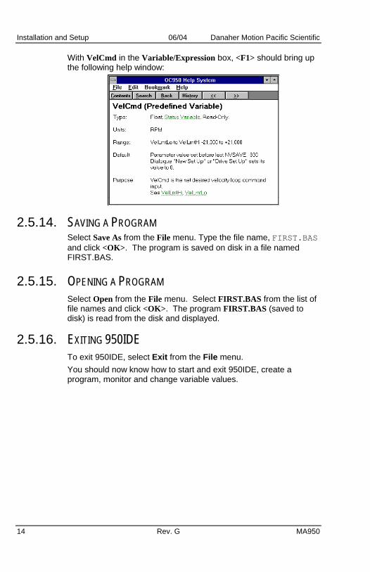
With VelCmd in the Variable/Expression box, <F1> should bring up the following help window:
2.5.14. SAVING A PROGRAM Select Save As from the File menu. Type the file name, FIRST.BAS and click <OK>. The program is saved on disk in a file named FIRST.BAS.
2.5.15. OPENING A PROGRAM Select Open from the File menu. Select FIRST.BAS from the list of file names and click <OK>. The program FIRST.BAS (saved to disk) is read from the disk and displayed.
2.5.16. EXITING 950IDE To exit 950IDE, select Exit from the File menu. You should now know how to start and exit 950IDE, create a program, monitor and change variable values.
14 Rev. G MA950

Danaher Motion Pacific Scientific 06/04 OC950 Interfaces and Connections
3. OC950 INTERFACES AND CONNECTIONS This section describes the OC950 interfaces and required connection information. The OC950 plugs into an SC900 servo controller.
WARNING
Install the OC950 with the servo controller's power off!
Turn the two lock screws (on the front panel of the OC950) until resistance is met to properly seat the OC950 into the base unit. A communications address selection switch resides on the OC950 printed circuit board and is accessible only when removed from the SC900 servo base unit. The OC950 external connections include: • Serial communications port (J51) • Bi-directional I/O connections, OCIO0-OCIO20 (J52) • Optional PacLAN™ communications port (J53)
3. 1 CONNECTION DIAGRAM
SHIELD/_I/O_RTN
SHIELD/_I/O_RTN
I/O_RTN
I/O_RTN
OCIO0OCIO1OCIO2OCIO3OCIO4
OCIO6OCIO7OCIO8OCIO9
OCIO10OCIO11OCIO12OCIO13OCIO14OCIO15OCIO16OCIO17OCIO18OCIO19OCIO20+5_VDC
LAN +LAN -
OCIO5
J51
J52 OC950OPTIONCARD
J53
I/O_RTN
RS-232_TXD
RS-485_TXD+
RS-485_RXD+RS-485_RXD-
RS-485_TXD-
RS-232_RXD+5_VDC
123456789
SERIA
L POR
TPacLA
NPR
OG
RA
MM
AB
LE I/O
12345678910111213141516171819202122232425
CS
MA950 Rev. G 15
OC950 Interfaces and Connections 06/04 Danaher Motion Pacific Scientific
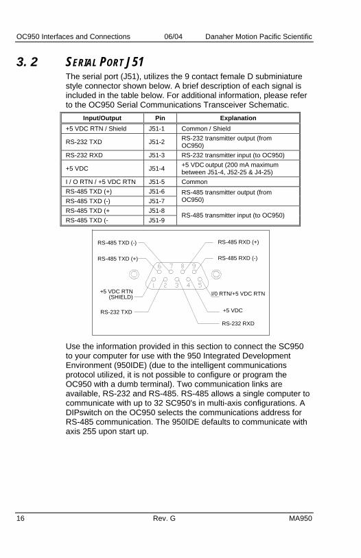
3. 2 SERIAL PORT J51 The serial port (J51), utilizes the 9 contact female D subminiature style connector shown below. A brief description of each signal is included in the table below. For additional information, please refer to the OC950 Serial Communications Transceiver Schematic.
Input/Output Pin Explanation +5 VDC RTN / Shield J51-1 Common / Shield
RS-232 TXD J51-2 RS-232 transmitter output (from OC950)
RS-232 RXD J51-3 RS-232 transmitter input (to OC950)
+5 VDC J51-4 +5 VDC output (200 mA maximum between J51-4, J52-25 & J4-25)
I / O RTN / +5 VDC RTN J51-5 Common RS-485 TXD (+) J51-6 RS-485 TXD (-) J51-7
RS-485 transmitter output (from OC950)
RS-485 TXD (+ J51-8 RS-485 TXD (- J51-9
RS-485 transmitter input (to OC950)
RS-485 TXD (-)
RS-485 RXD (-)RS-485 TXD (+)
RS-485 RXD (+)
RS-232 TXD
RS-232 RXD
+5 VDC RTN(SHIELD) I/0 RTN/+5 VDC RTN
+5 VDC
Use the information provided in this section to connect the SC950 to your computer for use with the 950 Integrated Development Environment (950IDE) (due to the intelligent communications protocol utilized, it is not possible to configure or program the OC950 with a dumb terminal). Two communication links are available, RS-232 and RS-485. RS-485 allows a single computer to communicate with up to 32 SC950's in multi-axis configurations. A DIPswitch on the OC950 selects the communications address for RS-485 communication. The 950IDE defaults to communicate with axis 255 upon start up.
16 Rev. G MA950

Danaher Motion Pacific Scientific 06/04 OC950 Interfaces and Connections
3.2.1. J51 SERIAL PORT T10 CONNECTIONS (RS-232) The T10 terminal requires a DC-9P 9-pin plug-in male D connector.
NOTE
The T10 terminal is a Burr-Brown TM2500.
SC950DA-9P
+5 VDC RTN2345
1
328
79
1
+5 VDC
+5 VDC RTN
TRANSMITTRANSMITRECEIVE
RECEIVEPOWER GND
SIGNAL GND5 VDC
T10DA-9P
1. Solder the cable leads to the SC950 mating connector and the
T10 connector as shown. 2. Assemble the connector housings. 3. Plug the connectors into the SC950 and T10 and affix the
connectors to the units.
3.2.2. PARAMETER SETUP Set up the T10 terminal as follows: 1. Enter the setup mode by pressing period ( . ) while power is
applied to the T10 (wait until the two letter prompt appears). Refer to the terminal manual for more information.
2. Enter the following values: VW = 4 Default LE = 0 Local Echo OFF
TM = 0 Character Mode EN = 1 Line Terminator (CR)
TD = 0 Turnaround Delay KC = 2 Key Click
BR = 2 Baud Rate (9600) KR = 1 Key Repeat
DF = 4 8 Bits, No Parity CU = 2 Cursor
HS = 0 Default (DTR asserted)
NOTE
The SC950 must be configured for 9600 baud (BaudRate = 9600), 8 bit, no parity data formats. Refer to the MA950-LR Reference Manual for additional information on configuring baud rate.
MA950 Rev. G 17

OC950 Interfaces and Connections 06/04 Danaher Motion Pacific Scientific
3. 3 S1 SWITCH The S1 switch sets the communication address for each OC950. RS-485 requires the ability to select different addresses for multi-drop communications. Looking down at the top of the OC950, the diagram below shows the location of switch S1.
1 8
SWITCHON
NOTE
Each SC950 subsystem connected to an RS-485 multi-drop installation or PacLAN must have a unique serial address.
The diagram below shows the S1 default switch settings. The OC950 factory default address is 255 (All switches off).
1 4 65 832 7
ON
OFF
The switches are:
On in the up position (away from number) Off in the down position (toward number)
NOTE
When using RS-232 communications, leave the address set at 255.
18 Rev. G MA950

Danaher Motion Pacific Scientific 06/04 OC950 Interfaces and Connections
MA950 Rev. G 19
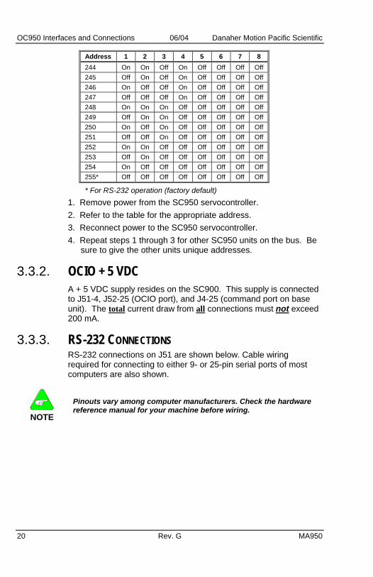
3.3.1. S1 ADDRESS TABLE Address 1 2 3 4 5 6 7 8 0 On On On On On On On On 1 Off On On On On On On On 2 On Off On On On On On On 3 Off Off On On On On On On 4 On On Off On On On On On 5 Off On Off On On On On On 6 On Off Off On On On On On 7 Off Off Off On On On On On 8 On On On Off On On On On 9 Off On On Off On On On On 10 On Off On Off On On On On 11 Off Off On Off On On On On 12 On On Off Off On On On On 13 Off On Off Off On On On On 14 On Off Off Off On On On On 15 Off Off Off Off On On On On 16 On On On On Off On On On 17 Off On On On Off On On On 18 On Off On On Off On On On 19 Off Off On On Off On On On 20 On On Off On Off On On On 21 Off On Off On Off On On On 22 On Off Off On Off On On On 23 Off Off Off On Off On On On 24 On On On Off Off On On On 25 Off On On Off Off On On On 26 On Off On Off Off On On On 27 Off Off On Off Off On On On 28 On On Off Off Off On On On 29 Off On Off Off Off On On On 30 On Off Off Off Off On On On 31 Off Off Off Off Off On On On 32 On On On On On Off On On 33 Off On On On On Off On On 34 On Off On On On Off On On 35 Off Off On On On Off On On 36 On On Off On On Off On On 37 Off On Off On On Off On On 38 On Off Off On On Off On On 39 Off Off Off On On Off On On 40 On On On Off On Off On On 240 On On On On Off Off Off Off 241 Off On On On Off Off Off Off 242 On Off On On Off Off Off Off 243 Off Off On On Off Off Off Off
OC950 Interfaces and Connections 06/04 Danaher Motion Pacific Scientific
20 Rev. G MA950
Address 1 2 3 4 5 6 7 8 244 On On Off On Off Off Off Off 245 Off On Off On Off Off Off Off 246 On Off Off On Off Off Off Off 247 Off Off Off On Off Off Off Off 248 On On On Off Off Off Off Off 249 Off On On Off Off Off Off Off 250 On Off On Off Off Off Off Off 251 Off Off On Off Off Off Off Off 252 On On Off Off Off Off Off Off 253 Off On Off Off Off Off Off Off 254 On Off Off Off Off Off Off Off 255* Off Off Off Off Off Off Off Off
* For RS-232 operation (factory default) 1. Remove power from the SC950 servocontroller. 2. Refer to the table for the appropriate address. 3. Reconnect power to the SC950 servocontroller. 4. Repeat steps 1 through 3 for other SC950 units on the bus. Be
sure to give the other units unique addresses.
3.3.2. OCIO + 5 VDC A + 5 VDC supply resides on the SC900. This supply is connected to J51-4, J52-25 (OCIO port), and J4-25 (command port on base unit). The total current draw from all connections must not exceed 200 mA.
3.3.3. RS-232 CONNECTIONS RS-232 connections on J51 are shown below. Cable wiring required for connecting to either 9- or 25-pin serial ports of most computers are also shown.
NOTE
Pinouts vary among computer manufacturers. Check the hardware reference manual for your machine before wiring.

Danaher Motion Pacific Scientific 06/04 OC950 Interfaces and Connections
3.3.3.1. Cabling Diagram
NOTE
Shielded wiring is recommended for the serial communications cable to minimize potential errors from electrical noise.
I/O RTN
RS-232 RXD
RS-232 TXD
9 CONTACT FEMALE D SUBMINIATURE CONNECTOR
TYPICAL CABLES
9 PIN FEMALE
25 PIN FEMALE
9 PIN MALE
9 PIN MALE
TO PC(9 PIN)
TO PC(25 PIN)
TO 0C950
TO 0C950
2
3
5
2
3
5
2
3
5
3
2
7
3.3.4. RS-485/RS-422 CONNECTIONS Up to 31 SC950s can be connected in parallel to a multi-drop master. The SC950s must each have a unique address, set using DIPswitch S1 (See S1 Switch). RS-485/RS-422 connections to J51 are shown below. A multi-drop interconnection diagram, showing multiple axes connected to a single host is also included.
3.3.4.1. RS-485/RS-422 Diagram
MA950 Rev. G 21

OC950 Interfaces and Connections 06/04 Danaher Motion Pacific Scientific
3.3.4.2. OC950 Serial Communications Transceiver Schematic
22 Rev. G MA950

Danaher Motion Pacific Scientific 06/04 Servo Loop Parameters
4. SERVO LOOP PARAMETERS This chapter describes setting parameters associated with the velocity and position loops. In some cases the user must adjust control loop parameters due to large mismatches between motor and load inertia, mechanical resonance, backlash, etc. This chapter provides guidance for handling these situations. Refer to Appendix A Selecting Motor Control Functionality for a description of the control loop architecture and control loop block diagrams.
NOTE
The two anti-resonant zeroes (ARZ0 and ARZ1) are assumed to both be off (set to zero) for this discussion.
4. 1 VELOCITY LOOP The velocity loop block diagram is shown in Figure 2 in Appendix A. Velocity loop bandwidth is the key indicator of system performance. Systems with fast settling time must have high velocity loop bandwidth. Conversely, if the velocity loop bandwidth is low, attempting to achieve fast settling time by increasing the position loop bandwidth, KPP, leads to overshoot and ringing.
4.1.1. VELOCITY LOOP BANDWIDTH The velocity loop bandwidth (fvc) is given by the equation:
TOT
T
TOT
Tvc
JKKVP
JKKVPHzf **138.0*2
2/3*)( ≈=π
where: KVP is the velocity loop proportional gain in amps/(rad/sec) KT is the 0-peak line-line motor torque constant in lb-in/amp JTOT is the total inertia (motor total + load total) in lb-in-sec2. (Any consistent set of units for KT, JTOT (i.e., MKS), that yields KT/JTOT in rad/sec2/amp will work)
The motor torque constant is the value of KT peak published in the Motion Control Solutions catalog.
NOTE
fvc is the unity gain open-loop crossover frequency of the idealized rigid single mass system.
MA950 Rev. G 23

Servo Loop Parameters 06/04 Danaher Motion Pacific Scientific
4.1.1.1. Default Bandwidths When creating a new program, the selections set KVP to achieve the velocity loop bandwidths shown below, assuming there is no load on the motor shaft and the motor has no mechanical brake or other secondary devices installed
NOTE
The bandwidth depends on the desired system response.
Gentle Medium Stifffvc Velocity Loop Bandwidth (Hz) 25 75 200
Load Inertia Bandwidth changes inversely with total inertia. If the load inertia equals the motor plus resolver inertia, the velocity loop bandwidth is half the values shown. If the load inertia is ten times the motor plus resolver inertia, the bandwidths are one eleventh these values. Clearly, KVP must be increased to compensate for increased load inertia if bandwidth is to be maintained. Typically, load inertia up to 3(motor + resolver) gives acceptable performance without further optimization. The most common servo setup problem is adding large load inertia without a corresponding increase in KVP. The value of KVP to achieve a desired bandwidth can easily be calculated as:
T
TOTvc
T
TOTvc
KJf
KJfKVP **26.72/3
**2≈=
π
Example To achieve 75 Hz bandwidth with an R32G motor having 20 to 1 load inertia = 0.011 lb-in-sec2:
JTOT1 = 0.00055 + 0.011 = 0.01155 lb-in-sec2
KT 2
= 4.4 lb-in/amp
43.14.4
01155.0*75*26.7 ==KVP
1 Motor plus resolver inertia (0.00055 lb-in-sec2) for the R32G motor is found in the catalog.
2 KT can be found in the catalog as KT peak (4.4 lb-in/amp) 24 Rev. G MA950

Danaher Motion Pacific Scientific 06/04 Servo Loop Parameters
MA950 Rev. G 25
950IDE can also be used to make the calculation. Simply enter the inertia ratio and 950IDE calculates the appropriate value for KVP to achieve 25, 75 or 180 Hz bandwidth, depending on the choice made for system response. There is no specific answer to the general question, “What should the bandwidth be?” In general, the higher the velocity loop bandwidth, the faster the settling time and the better the rejection of torque disturbances (increased stiffness). Typically, velocity loop bandwidths range from 30 to 100 Hz. However, too high a bandwidth can lower the damping of resonance in mechanical linkages, causing excessive ringing and/or wear in coupled mechanics. Remember, it is the resulting motion at the end of any mechanical linkages that typically matters — not the response at the motor shaft.
High Load Inertia It would seem that setting KVP is simply a matter of increasing its value to compensate for load inertia. Unfortunately, the following problems often interfere, particularly when the load inertia is large compared with the motor’s inertia: 1. Mechanical resonance between motor and load cause high
frequency oscillation. 2. Backlash between motor and load effectively unload the motor
over a small angle. Within this small angle the increased bandwidth results in oscillations.
3. Ripple in the velocity feedback signal results in large motor ripple current if KVP is large.
As a general rule, any system with KVP set higher than 5 times the medium bandwidth setting requires adjustments to the default ARF0 and ARF1 settings.
Resonance Mechanical resonance is caused by springiness between motor inertia and load inertia. This may result from belts, flexible couplings, or the torsion stiffness of shafts. In general, the stiffer the couplings, the higher the resonance frequency and the easier it is to tune the system for good performance. If the velocity loop breaks into an oscillation at a frequency well above the calculated velocity loop bandwidth, a resonance problem may exist. A second symptom is that the frequency of oscillation is relatively constant in the presence of changes to ARF0 and ARF1.

Servo Loop Parameters 06/04 Danaher Motion Pacific Scientific
ARF0 and ARF1 Two digital anti-resonant low-pass filters, ARF0 and ARF1, are included in the velocity loop. Their purpose is to lower the gain above fvc, especially at any resonant frequency greater than fvc so oscillations do not occur. Default values, also a function of the selected system response, are shown below:
Gentle Medium Stiff ARF0 (Hz) 100 150 1500 ARF1 (Hz) 200 750 1x10⁵
If the velocity loop bandwidth cannot be raised to an acceptable value without encountering a resonant oscillation: 1. Set both ARF0 and ARF1 to 400 Hz and set KVP low enough to
prevent oscillation. 2. Increase KVP slowly until oscillation at the resonant frequency
just begins. 3. Reduce KVP slightly until the oscillation just stops. Compute
the velocity loop bandwidth using the formula given at the beginning of this section. If the velocity loop bandwidth is less than .25 times the value of ARF0 and ARF1, then proceed to Step 4. Otherwise, go to Step 5.
4. Decrease both ARF0 and ARF1 by 20% and go back to Step 2. 5. The velocity loop bandwidth should now be approximately one
quarter the value of ARF0 and ARF1. For margin, reduce KVP, ARF0, and ARF1 by 20%.
Backlash Some backlash may be unavoidable, especially when gear reduction is used. If backlash is present, the inertia match must be good (load inertia should be roughly equal to motor inertia) for good servo performance. Gearing reduces the inertia reflected to the motor by the square of the gear reduction from motor to load. Select a gear ratio to give the required match.
Current Ripple The velocity feedback signal in standard SC900 drives operating with the standard 20 arc-min resolver can have up to 3% p-p ripple. The resulting motor torque current ripple, with no ARF0/ARF1 filtering, can be calculated using:
KVPrpmSpeed *602*)(*
1003 p)-p (amps rippleCurrent π
=
»0.003*Speed(rpm)*KVP
26 Rev. G MA950

Danaher Motion Pacific Scientific 06/04 Servo Loop Parameters
MA950 Rev. G 27
There is cause for concern when this p-p number exceeds 40% of the drive’s or motor’s current rating. Monitor the motor current using Dac Monitors on J4-3 to ensure actual ripple current, with ARF0/ARF1 filtering, is not excessive. Motor current ripple is reduced by lowering ARF0's and ARF1's low-pass filter break frequencies. This benefit is limited by velocity loop bandwidth and stability constraints. Velocity feedback ripple and motor current ripple are also reduced by specifying a higher accuracy resolver.
KVI KVI sets the “lag-break” frequency of the velocity loop. KVI is equal to the frequency in Hz where the velocity loop compensation transitions from predominantly integral characteristics to predominantly proportional characteristics. Drive rejection of torque disturbances increase as KVI increases. Default values for KVI are: Gentle Medium Stiff KVI (Velocity Loop Lag-Break Freq. (Hz)) 1.7 5.0 13.3
If the drive is to be used within a position loop (either with BlkType=2 or when using an external position drive and BlkType=1), KVI should be equal to or less than 0.1 times the velocity loop bandwidth. If no position loop is used, set KVI to 0.25 times the velocity loop bandwidth (or higher if some ringing can be tolerated). In general, the response to a velocity command step (or truncated ramp) has velocity overshoot for non-zero values of KVI.
4. 2 POSITION LOOP When BlkType = 2, a position loop is configured outside the velocity loop. Figure 3 in Appendix A illustrates the structure of the position loop. The velocity loop must be set up and evaluated in terms of bandwidth before attempting to setup the position loop.
KPP The position loop proportional gain, KPP, determines the settling time of the position loop. KPP is the bandwidth of the position loop, in Hz, assuming an ideal velocity loop. Default values for KPP are:
Gentle Medium Stiff KPP (Position Loop Bandwidth (Hz)) 5 15 50

Servo Loop Parameters 06/04 Danaher Motion Pacific Scientific
In general, the higher the value of KPP, the faster the settling time. However, trying to set KPP to a high value with inadequate velocity loop bandwidth results in overshoot and ringing. A good trade off is to set KPP 0.2 times the velocity loop bandwidth. Slightly higher values can be used if overshoot can be tolerated.
KVFF KVFF is the velocity feed forward gain. In the absence of velocity feed forward (KVFF = 0), the commanded velocity is proportional to the position (following) error. This means that the actual position lags the commanded position by a value proportional to the speed. The error is smaller for larger values of KPP. The following table gives a feel for the following error magnitude.
Speed(rpm)
KPP(Hz)
Following Error (revolutions)
1000 10 0.27 2000 10 0.53 5000 10 1.33 1000 20 0.13 2000 20 0.27 5000 20 0.66
NOTE
Following error can easily exceed one complete motor revolution. In many electronic gearing applications, such following errors are not acceptable (real gears don’t have following errors!) Also, stepper systems don’t have such errors.
Feed forward takes advantage of the fact that the SC900 DSP knows the frequency of the encoder or step inputs and knows how fast the motor should be going at any given instant. All or part of this velocity can be added to the velocity command to reduce following error. If KVFF is set to 100 (%), the steady state following error reduces to zero.
Overshoot Setting KVFF equal to 100% can result in position overshoot. Somewhat lower values may be required, if this is a problem. KVFF set to 70%-80% typically achieves the fastest step response with no overshoot. However, setting KVFF to less than 100% gives steady state following error when running at constant speed.
28 Rev. G MA950

Danaher Motion Pacific Scientific 06/04 Servo Loop Parameters
4. 3 ADVANCED VELOCITY LOOP TUNING
Continuous Time Transfer Function Approximation The transfer function for the velocity loop compensation block is given below
11
11
)( 2
2
++
++
=
⎟⎠⎞
⎜⎝⎛
⎟⎠⎞
⎜⎝⎛
fff
zzz
sQ
sQ
sVelErrFVelErr
s
s
ω
ω
ω
ω
⎟⎠⎞
⎜⎝⎛ +
++
++
=
⎟⎠⎞
⎜⎝⎛
⎟⎠⎞
⎜⎝⎛
sKVIKVP
sQ
sQ
sVelErrICmd
fff
zzz
s
s)(21)(
11
11
)( 2
2
π
ω
ω
ω
ω
For ARx0 > 0 both roots are real and:
)1)(0(2 ARxARxx πω =
10)1)(0(
ARxARxARxARxQx
+=
For ARx0 < 0 roots are a complex pair and:
)0(2 ARxx πω =
1ARxQx =
NOTE
FvelErrVelErr
(s)The numerator of reduces to 1 when ARZ0 and ARZ1 both=0.
s2p ARZx
+1If ARZ0 or ARZ1=0 the numerator reduces to
MA950 Rev. G 29

Servo Loop Parameters 06/04 Danaher Motion Pacific Scientific
Discrete Time Transfer Function The velocity loop compensation is actually implemented as a digital discrete time system function on the DSP. The continuous time transfer function is converted to the discrete time domain by a backward Euler mapping:
( )zsT
s 111 −−®
where Ts = 250 µs
30 Rev. G MA950

Danaher Motion Pacific Scientific 06/04 Troubleshooting
MA950 Rev. G 31
5. TROUBLESHOOTING This section covers maintenance and troubleshooting of the SC950 servo controller. The SC950 series servo controllers are designed for minimum maintenance. Remove superficial dust and dirt from the unit using clean, dry, low-pressure air. Performed as needed, this procedure minimizes problems due to dust and dirt buildup.
5. 1 TROUBLESHOOTING The system status display located on the front panel indicates unit status and is useful for troubleshooting. 0 means the drive is neither faulted nor enabled, while 8 means the drive is not faulted and enabled. 0. means the drive is disabled and a program is running, 8. means the drive is enabled and a program is running. Alternating 8 means actively inhibiting CW motion and alternating 8 means actively inhibiting CCW motion.
5.1.1. SYSTEM STATUS Status LED Value Fault Meaning (Blinking) 1 1 Velocity feedback (VelFB)
over speed (Blinking) 2 2 Motor Over-Temp (Blinking) 3 3 Drive Over-Temp (Blinking) 4 4 Drive I*t (Blinking) 5 5 l-n Fault (9x3) (Blinking) 6 6 Control ±12 V supply under
voltage (Blinking) 7 7 Output over current or bus
over voltage (Blinking) 9 9 Shunt regulator overload (Blinking) A 10 Bus OV detected by DSP (Blinking) b 11 Auxiliary +5 V Low (Blinking) C 12 Not assigned (Blinking) d 13 Not assigned (Solid) E* 14 Processor throughput fault (Blinking) E* 14 Power Up Self Test Failure (Alternating) E1 225 Bus UV, Bus Voltage
VBusThresh (Alternating) E2 226 Ambient Temp Too Low (Alternating) E3 227 Encoder commutation align
failed (Only CommSrc=1) (Alternating) E4 228 Drive software incompatible
with NV memory version

Troubleshooting 06/04 Danaher Motion Pacific Scientific
32 Rev. G MA950
Status LED Value Fault Meaning (Alternating) E5* 229 Control Card hardware not
compatible with drive software version
(Alternating) E6 230 Drive transition from unconfigured to configured while enabled
(Alternating) E7 231 Two AInNull events too close together
(Alternating) F1 241 Excessive Position Following Error
(Alternating) F2* 242 Program Checksum Error (Memory Error)
(Alternating) F3* 243 Parameter Checksum Error (Memory Error)
(Alternating) F4 244 Run Time Error (Err) *FaultReset cannot reset these faults. See Extended Faultcodes for further information on Blinking E, Blinking 1 and Alternating F2 and F3.
5.1.2. EXTENDED FAULTCODES LED Display Value of ExtFault Description 1 1 VelFB < 21038 1 2 VelFB < 1.5*max(VelLmtxx) E 0 No ExtFault information E 1 Resolver calibration data
corrupted E 2 Excessive DC offset in current
feedback sensor E 3 DSP incompletely reset by line
power dip E 6 Excessive DC offset in Analog
Command A/D E 7 Unable to determine option card
type E 8 DSP stack overflow E 10 Firmware and control card ASIC
incompatible E 11 Actual Model does not match
value in nonvolatile memory E 12 Unable to determine power
stage E 15 RAM failure E 16 Calibration RAM failure F2 13 Control card nonvolatile
parameters corrupt F3 14 Option card nonvolatile
parameters corrupt

Danaher Motion Pacific Scientific 06/04 Troubleshooting
MA950 Rev. G 33
5.1.3. TROUBLESHOOTING TABLE Problem (and system
status numbers) Possible cause Action
No control power.
Check that SC955 has AC switch set to INT or SC952, SC953 and SC954, have 115 VAC or 230 VAC applied to J3 pins 5,6.
System status display not lit.
Blown control power fuse.
Replacement of fuses within the drive is rarely useful and not recommended. A blown fuse is a strong indication that the drive is defective and should be returned to the factory for repair.
Controller unconfigured (U/C). New controller. Perform controller setup.
Incorrect resolver phasing. Verify proper phasing.
Resolver conversion overspeed (1). Open or intermittent
resolver connector. Check connector and cable.
Motor PTC pins open.
Connect PTC pins (J3-8 and J3-9).
Temperature overload due to high motor ambient temperature or excessive RMS torque.
Lower ambient temperature. Operate within continuous torque rating.
Motor over-temperature (2).
Motor PTC damaged.
Check motor PTC for resistance ≤ 310 Ω.
Temperature overload due to:
High ambient temperature.
Lower ambient temperature to below 50° C (60° C, if derated).
Restriction of cooling air due to insufficient space around unit.
Provide sufficient cooling space.
Operation above continuous power rating.
Operate within continuous power rating. Add fan option to controller to boost continuous rating.
Controller over-temperature (3).
Fan inoperative. Return to factory for fan replacement.
IT Fault (4). Excessive time at peak current.
Check time spent at peak current. If excessive, change profile or load. (Use larger motor/drive.)
Motor cable short to ground. Motor winding short.
Check motor cable. Line-neutral fault (5).
Internal failure. Contact distributor.

Troubleshooting 06/04 Danaher Motion Pacific Scientific
34 Rev. G MA950
Problem (and system status numbers) Possible cause Action
External short on signal connectors.
Remove connectors and reapply power.
Insufficient voltage on J1-5 and J1-6.
Check voltage with meter ( ≥ 90 V).
Servocontroller logic supply under-voltage (6).
Internal failure. Contact distributor. Excessive ac input voltage.
Reduce AC input voltage to below 264 VAC.
Output short circuit. Check for short. Motor cabling wires shorted together. Check for short.
Motor cabling shorted to ground. Check for short.
Open or missing regen resistor. Check regen wiring.
Internal motor winding short circuit.
Check for short.
Output over-current, or bus over-voltage (7).
Insufficient motor inductance. SC952 > 4 mH SC953 > 2 mH SC954 > 1 mH SC955 > 0.5 mH
Check current loop compensation parameters in software. Replace motor with motor of correct inductance.
Drive enabled (8) Normal Operation None. Drive enabled, no faults (8.) Program running. None.
Enabled, inhibits active. (8 ) CCW Inhibit active (8 ) CW Inhibit active (8 ∩) CCW&CW Inhibit active
Drive Inhibits are active. Deactivate inhibit inputs.
External enable not applied.
Apply enable input to pin J4-6.
Internal fault. Contact distributor. Software enable not on. Set Enable variable to 1.
Unit will not enable (does not display 8 when enable applied).
No bus power. (9x4, 9x5 only) Apply Bus power.
Problem (and system status numbers) Possible cause Action
Excessive regen in application
Increase cycle time. Reduce the inertia. Add external regen with higher wattage.
Improper external regen wiring or components on J5.
Check connections on J5.
Shunt regulator overload (9)
Internal failure. Return to factory for repair. Bus AC input overvoltage. Check AC voltage < 264.
Bus overvoltage (A) Internal failure. Return to factory for repair.

Danaher Motion Pacific Scientific 06/04 Troubleshooting
MA950 Rev. G 35
Problem (and system status numbers) Possible cause Action
Short on pin J52-25.
Remove J52 connector. Reapply AC power.
Short on pin J51-4. Remove J51 connector. Reapply AC power.
Short on pin J4-25. Remove J4 connector. Reapply AC power.
+5 V low ( b )
Internal failure. Return to factory for repair.
Intermittent failure from environment noise.
Unconfigure drive and cycle AC power. Check ground connections. Check for excessive ground noise and loose AC connections.
Microprocessor throughput fault. (E)
Internal failure or firmware version conflict.
Return to factory for repair.
VBusThresh is set too high.
Bus Under-voltage (E1) VBus < VBusThresh VBus is low because bus AC power is low. Check J1-1, J1-2, and J1-3.
Ambient temperature <0° C
Measure temperature in control cabinet. Condition if necessary.
Ambient temperature too low (E2)
Internal failure. Return to factory for repair.
Not enough current to lock the motor shaft to proper position within 1 second.
Check IlmtPlus and IlmtMinus. If vertical load, reduce load or increase motor/drive. Verify motor brake releases properly.
Encoder commutation alignment failure (E3)
Internal failure. Return to factory for repair.
Incompatible 950IDE (E4)
950IDE version is incompatible with drive’s NV memory version.
Verify that FWV and 950IDE version are the same. If FWV = 200, then 950IDE should be version 2.0 or higher.
Resolver wiring error.
Remove J2 and J3 connectors. Cycle power. If fault is now a “2”, then correct resolver excitation wiring.
Control card hardware not compatible with drive software version (E5)
Internal failure. Return to factory for repair.
Hardware Enable input active.
Disable hardware Enable input. Re-configure drive then cycle power. Drive transition from
UnConfigured to Configure while enabled (E6)
Enable inactive during several configurations, drive still faults.
Return for repair.
Two AInNull events too close together. (E7)
Connection to AInNull input has switch bounces.
Use BDOutX to trigger the AInNull input. Replace switch if no fault occurs.

Troubleshooting 06/04 Danaher Motion Pacific Scientific
36 Rev. G MA950
Problem (and system status numbers) Possible cause Action
CwInh and/or CcwInh held low while commanding motion.
Check CwInh and CcwInh inputs and variables.
Loss of feedback information.
Disable drive and spin motor shaft by hand. Verify Position variable is changing. If not, swap out motor/cables or drive with know good spare to isolate defective part.
Open motor phase. Check wiring and motor winding for open circuit.
Loss of motor power. Bus voltage is low.
Following error overflow (F1)
Tuning Wizard incomplete.
No motor selected, therefore cannot respond.
Checksum fault while reading user program memory during power up.
Cycle AC power. Download the program.
User Program Checksum Fault (F2)
Memory allocation error. Program is writing to a variable address location that has not been dimensioned.
Check Dim section of program for string variables and arrays.
Check for AC momentary glitch. Do not interrupt program or waveshape download with keystroke or power cycle.
Checksum fault reading NV memory. Typically during power cycle or after program download.
Download a new parameter set. Download a program with a valid parameters section.
Parameter checksum error (F3)
Internal failure. Return to factory for repair.
Run time error (F4) Programming error.
Read error number in Output Window or check value of Err in the variables window. Look up values in run-time error table and make necessary corrections to your program.
Processor failure ( h ) Excessive noise in application or internal failure.
Cycle AC power. Return to factory for repair.
Danaher Motion Pacific Scientific 06/04 Troubleshooting
MA950 Rev. G 37
Problem (and system status numbers) Possible cause Action
Seized load or excessive load friction.
Reduce load.
Reset command on J4-7. Remove reset from J4-7.
No bus power. Apply bus power.
Unit is enabled, no system status faults (status code 8), but motor does not respond.
Open motor connections. Connect motor.
Improper shielding and grounding. Shield cabling correctly.
Motor oscillates or runs erratically. Improper drive set
up. Review set up procedure.
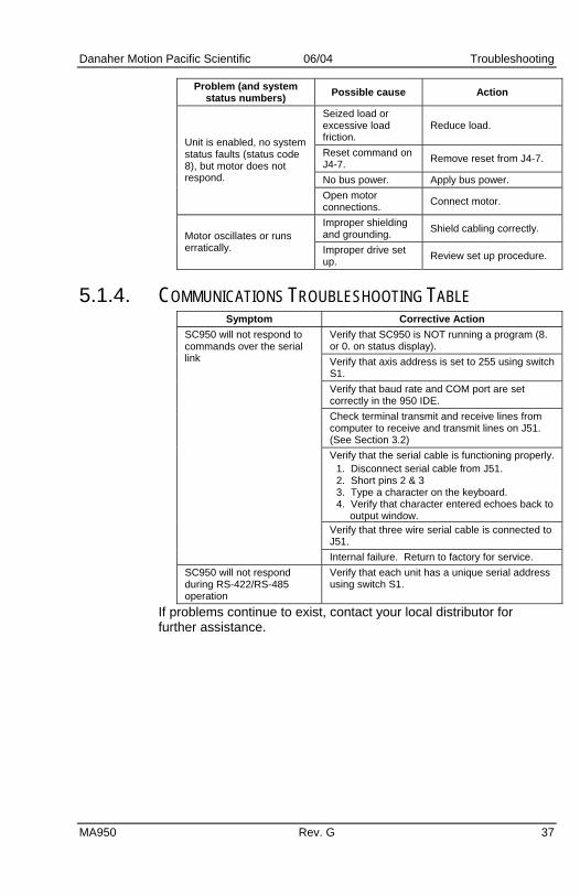
5.1.4. COMMUNICATIONS TROUBLESHOOTING TABLE Symptom Corrective Action
Verify that SC950 is NOT running a program (8. or 0. on status display). Verify that axis address is set to 255 using switch S1. Verify that baud rate and COM port are set correctly in the 950 IDE. Check terminal transmit and receive lines from computer to receive and transmit lines on J51. (See Section 3.2) Verify that the serial cable is functioning properly.
1. Disconnect serial cable from J51. 2. Short pins 2 & 3 3. Type a character on the keyboard. 4. Verify that character entered echoes back to
output window. Verify that three wire serial cable is connected to J51.
SC950 will not respond to commands over the serial link
Internal failure. Return to factory for service. SC950 will not respond during RS-422/RS-485 operation
Verify that each unit has a unique serial address using switch S1.
If problems continue to exist, contact your local distributor for further assistance.

Troubleshooting 06/04 Danaher Motion Pacific Scientific
38 Rev. G MA950
5.1.5. Contact Information Danaher Motion products are available world-wide through an extensive authorized distributor network. These distributors offer literature, technical assistance and a wide range of models off the shelf for fastest possible delivery. Danaher Motion sales engineers are conveniently located to provide prompt attention to customers' needs. Call the nearest office listed for ordering and application information or for the address of the closest authorized distributor. Danaher Motion Customer Support Phone: (815) 226-2222 Email: [email protected] Web: www.DanaherMotion.com

Danaher Motion Pacific Scientific 06/04 Appendix A Selecting Motor Control Functionality
MA950 Rev. G 1
APPENDIX A SELECTING MOTOR CONTROL FUNCTIONALITY
The SC900 family has three distinct modes of controlling the motor shaft and two distinct sources for the shaft command: Modes • Torque Control • Velocity Control • Position Control Commands • Analog Command • Program Control
A.1 TORQUE BLOCK MODES
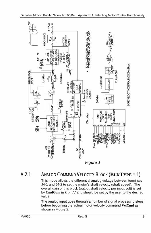
A.1.1 ANALOG COMMAND TORQUE BLOCK (BLKTYPE = 0) This mode allows the differential analog voltage between terminals J4-1 and J4-2 to set the motor’s terminal torque current amplitude. Since the actual motor current amplitude (IFB) times the motor’s 0-peak line-line torque constant KT times is the shaft torque, then the analog input directly controls motor shaft torque. The overall gain of this block, i.e. the output current amplitude in amps per input volt, is set by the CmdGain parameter directly in A/V and should be set by the user to the desired value. Figure 1 shows the analog torque block mode has the same signal processing as a velocity loop except that the velocity error signal (VelErr) is set to VelCmd not to (VelCmd - VelFB) and that the VelCmd clamp is bypassed. Thus, the analog input goes through a number of signal processing steps before becoming the motor torque current command ICmd. 1. Analog differential amplifier with 1200 Hz low pass filter. 2. High resolution A/D sampled at the velocity loop update rate and
added to ADOffset. 3. ADF0 adjustable low pass filter to become AnalogIn. 4. Bypass the VelLmtHi, VelLmtLo clamp. 5. Velocity error variable VelErr is set equal to VelCmdA. 6. The anti-resonance second order velocity loop compensation
block controlled by ARF0, ARF1, ARZ0, and ARZ1 to become FVelErr.
7. The proportional and integral velocity loop compensation block controlled by KVP and KVI, respectively.

Appendix A Selecting Motor Control Functionality 06/04 Danaher Motion Pacific Scientific
8. Through IlmtPlus and IlmtMinus current clamp to become ICmd (motor torque current).
Although this looks like a large amount of processing, the options allow tailoring the response to fit a particular application. Typically, most signal blocks are set to directly pass the signal so ICmd = CMDGain*(AnalogIn) as directly as possible. The set of parameters below accomplish this: ADF0 = 100,000 Hz to bypass, 1000 Hz by auto set up ARF0 = 100,000 Hz ARF1 = 100,000 Hz ARZ0 = 0 (not active) ARZ1 = 0 (not active) KVP = 1 A/rad/sec KVI = 0 Hz
WARNING
KVP must be set to 1 A/rad/sec for the units on CmdGain to be correct. If CmdGain is set to 1 Amp/V and KVP to 2 A/rad/sec, an analog input of 1 volt incorrectly gives 2 amps of output torque current amplitude.
When changing BlkType to 0 to get an analog torque block, set KVP to 1, KVI to 0, and the other items in the above list to appropriate values to get the system working as desired.
2 Rev. G MA950
Danaher Motion Pacific Scientific 06/04 Appendix A Selecting Motor Control Functionality
Figure 1
A.2.1 ANALOG COMMAND VELOCITY BLOCK (BLKTYPE = 1) This mode allows the differential analog voltage between terminals J4-1 and J4-2 to set the motor’s shaft velocity (shaft speed). The overall gain of this block (output shaft velocity per input volt) is set by CmdGain in krpm/V and should be set by the user to the desired value. The analog input goes through a number of signal processing steps before becoming the actual motor velocity command VelCmd as shown in Figure 2.
MA950 Rev. G 3

Appendix A Selecting Motor Control Functionality 06/04 Danaher Motion Pacific Scientific
Figure 2
1. Analog input differential amplifier with 1200 Hz low pass filter. 2. High resolution A/D sampled at the velocity loop update rate and
added to ADOffset. 3. ADF0 adjustable low pass filter to become AnalogIn. 4. Range clamped by VelLmtHi and VelLmtLo.
4 Rev. G MA950

Danaher Motion Pacific Scientific 06/04 Appendix A Selecting Motor Control Functionality
The actual velocity command (VelCmd) is then combined with the measured shaft velocity (VelFB) and processed by the velocity loop compensation to create the motor torque current command (ICmd). The detailed signal processing steps to create ICmd are listed below and shown in Figure 1. 1. VelErr set equal to (VelCmdA - VelFB) 2. The anti-resonance second order velocity loop compensation
block controlled by ARF0, ARF1, ARZ0, and ARZ1 to become FVelErr.
3. The proportional and integral velocity loop compensation block controlled by KVP and KVI, respectively.
4. Through IlmtPlus and IlmtMinus current commands clamp to become ICmd (motor torque current command).
For more information on tuning the velocity loop see Servo Loop Parameters.
A.3 POSITION BLOCK MODES
A.3.1 DIGITAL COMMAND POSITION BLOCK (BLKTYPE = 2) This mode is just a velocity block mode with the VelCmd coming from the position loop. See Figure 3. In particular, PosError = PosCommand - Position Feedback.
( )⎥⎦⎤
⎢⎣⎡+= PosCommanddtdKVFFPosErrKPPVelCmd *
100**2π
where: PosCommand is the position command in counts KPP is the proportional position loop gain KVFF is the velocity feed forward gain percentage.
When the SC900 is disabled and BlkType = 2, PosCommand is set to the position feedback value. This insures that when the drive is enabled, it picks up motion from its present position.
MA950 Rev. G 5

Appendix A Selecting Motor Control Functionality 06/04 Danaher Motion Pacific Scientific
Figure 3
6 Rev. G MA950

Danaher Motion Pacific Scientific 06/04 Appendix B OC950 Specifications
APPENDIX B OC950 SPECIFICATIONS
B.1 OC950 J51 SERIAL INTERFACE Type RS-232/RS485 (address selectable) Baud Rate 19200 or 9600 (software selectable) Parity No parity Data Word 10 bits: 1 start, 8 Data, 1 stop Connector 9 Contact Female D-subminiature
B.2 OC950 J52 PROGRAMMABLE INPUTS / OUTPUTS Input/Output Type & Quantity 21 Bi-Directional Channels Logic Voltage 5 to 24 volt, 40 V Absolute Maximum Input Channel
Pull-up resistor 10 k Ω to + 12 VDC Low-to-High Logic Threshold 3.5 volts maximum High-to-Low Logic Threshold 1.0 volts minimum Hysteresis 0.5 volts minimum, 1.5 volts maximum Filter RC Time constant 100 microseconds
B.3 OUTPUT CHANNEL Device Open Drain DMOS Transistor Sink Capability 100 mA Drain-to-Source - Impedance 5 Ω typical, 9.5 Ω maximum at 125° C Connector 25 Contact Female D-subminiature
B.4 USER +5 V POWER (OC950 J51-4, J52-25 and SC900 J4-25) Output Voltage 5 volts ± 5% Output Current 200 mA, Maximum
NOTE
Output current is the combined current of all three connection points.
MA950 Rev. G 1

Appendix B OC950 Specifications 06/04 Danaher Motion Pacific Scientific
2 Rev. G MA950
B.5 OC950 J53 (OPTIONAL) PACLAN Data Rate 2.5 MBaud Termination Impedance 93 Ω Cable Type coaxial, RG62U Maximum Bus Segment Length 305 meters Maximum Stations/Segment 8 Connector Standard BNC
B.6 NVRAM - PROGRAM MEMORY Data Retention 10 Years