Embed Size (px)
Citation preview
Machine Automation ControllerNX-series
Load Cell Input Unit
Load Cell Input Unit
User’s Manual
W565-E1-05
NX-RS

All rights reserved. No part of this publication may be reproduced, stored in a retrieval system, or transmitted, in any form, or by any means, mechanical, electronic, photocopying, recording, or otherwise, without the prior written permission of OMRON.
No patent liability is assumed with respect to the use of the information contained herein. Moreover, because OMRON is constantly striving to improve its high-quality products, the information contained in this manual is subject to change without notice. Every precaution has been taken in the preparation of this manual. Neverthe-less, OMRON assumes no responsibility for errors or omissions. Neither is any liability assumed for damages resulting from the use of the information contained in this publication.
• Sysmac and SYSMAC are trademarks or registered trademarks of OMRON Corporation in Japan and other countries for OMRON factory automation products.
• Microsoft, Windows, Windows Vista, Excel, and Visual Basic are either registered trademarks or trademarks of Microsoft Corporation in the United States and other countries.
• EtherCAT® is registered trademark and patented technology, licensed by Beckhoff Automation GmbH, Germany.
• Safety over EtherCAT® is registered trademark and patented technology, licensed by Beckhoff Automation GmbH, Germany.
• ODVA, CIP, CompoNet, DeviceNet, and EtherNet/IP are trademarks of ODVA.
• The SD and SDHC logos are trademarks of SD-3C, LLC.
Other company names and product names in this document are the trademarks or registered trademarks of their respective companies.
Trademarks
Copyrights
NOTE
Microsoft product screen shots reprinted with permission from Microsoft Corporation.
1
Introduction
NX-series Load Cell Input Unit User’s Manual (W565)
Introduction
Thank you for purchasing an NX-series Load Cell Input Unit.
This manual contains information that is necessary to use the NX-series Load Cell Input Unit. Please read this manual and make sure you understand the functionality and performance of the NX-series Load Cell Input Unit before you attempt to use it in a control system.
Keep this manual in a safe place where it will be available for reference during operation.
This manual is intended for the following personnel, who must also have knowledge of electrical sys-tems (an electrical engineer or the equivalent).
• Personnel in charge of introducing FA systems.
• Personnel in charge of designing FA systems.
• Personnel in charge of installing and maintaining FA systems.
• Personnel in charge of managing FA systems and facilities.
For programming, this manual is intended for personnel who understand the programming language specifications in international standard IEC 61131-3 or Japanese standard JIS B 3503.
This manual covers the following product.
• NX-series Load Cell Input Unit
NX-RS
Intended Audience
Applicable Products
CONTENTS
2 NX-series Load Cell Input Unit User’s Manual (W565)
CONTENTS
Introduction ..............................................................................................................1Intended Audience....................................................................................................................................... 1Applicable Products ..................................................................................................................................... 1
Relevant Manuals .....................................................................................................8
Manual Structure ......................................................................................................9Page Structure and Icons ............................................................................................................................ 9Special Information .................................................................................................................................... 10Precaution on Terminology ........................................................................................................................ 11
Terms and Conditions Agreement ........................................................................12Warranty, Limitations of Liability ................................................................................................................ 12Application Considerations ........................................................................................................................ 13Disclaimers ................................................................................................................................................ 13
Safety Precautions .................................................................................................14Definition of Precautionary Information...................................................................................................... 14Symbols ..................................................................................................................................................... 14Warnings.................................................................................................................................................... 15Cautions..................................................................................................................................................... 16
Precautions for Safe Use.......................................................................................18
Precautions for Correct Use..................................................................................23
Regulations and Standards...................................................................................24Conformance to EU Directives .................................................................................................................. 24Conformance Requirement to EU Directives............................................................................................. 25Conformance to UL and CSA Standards ................................................................................................... 25Conformance to Shipbuilding Standards ................................................................................................... 25Conformance to KC Certification ............................................................................................................... 25Software Licenses and Copyrights ............................................................................................................ 26
Unit Versions ..........................................................................................................27Unit Versions.............................................................................................................................................. 27Unit Versions and Support Software Versions ........................................................................................... 28
Related Manuals .....................................................................................................29
Terminology ............................................................................................................33
Revision History .....................................................................................................36
Sections in this Manual .........................................................................................37
Section 1 Features and System Configuration
1-1 Features of Load Cell Input Unit .......................................................................................... 1-2
1-2 System Configuration ........................................................................................................... 1-41-2-1 System Configuration in the Case of a CPU Unit........................................................................ 1-41-2-2 System Configuration of Slave Terminals ...................................................................................1-51-2-3 Configuration Examples of Weight Measurement System.......................................................... 1-71-2-4 Configuration Examples of Force Measurement System............................................................ 1-9
3
CONTENTS
NX-series Load Cell Input Unit User’s Manual (W565)
1-3 Unit Models, Functions and Support Software................................................................. 1-101-3-1 List of Unit Models .................................................................................................................... 1-101-3-2 List of Functions........................................................................................................................ 1-101-3-3 Support Software ...................................................................................................................... 1-12
Section 2 Specifications and Application Procedures
2-1 Specifications ........................................................................................................................ 2-22-1-1 General Specifications................................................................................................................ 2-22-1-2 Individual Specifications ............................................................................................................. 2-3
2-2 Operating Procedures........................................................................................................... 2-7
Section 3 Part Names and Functions
3-1 Part Names............................................................................................................................. 3-2
3-2 Indicators ............................................................................................................................... 3-3
3-3 Terminal Blocks ..................................................................................................................... 3-5
Section 4 Installation and Wiring
4-1 Installing NX Units................................................................................................................. 4-2
4-2 Wiring the Power Supply and Ground................................................................................. 4-3
4-3 Wiring the Terminals ............................................................................................................. 4-44-3-1 Wiring the Screwless Clamping Terminal Blocks........................................................................ 4-44-3-2 Checking the Wiring.................................................................................................................. 4-19
4-4 Wiring the Connected External Devices............................................................................ 4-204-4-1 Terminal Block Arrangement..................................................................................................... 4-214-4-2 Wiring Example with 6-wire Connection ................................................................................... 4-224-4-3 Wiring Example with 4-wire Connection ................................................................................... 4-224-4-4 Wiring Example of Parallel Connection .................................................................................... 4-23
Section 5 I/O Refreshing
5-1 I/O Refreshing ........................................................................................................................ 5-25-1-1 I/O Refreshing from CPU Units to NX Units ............................................................................... 5-25-1-2 I/O Refreshing from CPU Units or Industrial PCs to Slave Terminal .......................................... 5-35-1-3 Calculating the I/O Response Times of NX Units ....................................................................... 5-4
5-2 I/O Refreshing Methods ........................................................................................................ 5-55-2-1 Types of I/O Refreshing Methods ............................................................................................... 5-55-2-2 Setting the I/O Refreshing Methods............................................................................................ 5-65-2-3 Restrictions in Refresh Cycles.................................................................................................... 5-75-2-4 I/O Refreshing Method Operation............................................................................................... 5-8
Section 6 Specifications of Input Conversion and I/O Data
6-1 Specifications of Input Conversion ..................................................................................... 6-26-1-1 General Properties of the Load Cell ........................................................................................... 6-26-1-2 Terms Used in Weight Measurement.......................................................................................... 6-46-1-3 Detailed Specifications of Input Conversion ............................................................................... 6-5
6-2 Specifications of I/O Data ................................................................................................... 6-136-2-1 Data Items for Allocation to I/O................................................................................................. 6-13
CONTENTS
4 NX-series Load Cell Input Unit User’s Manual (W565)
6-2-2 Data Details............................................................................................................................... 6-15
Section 7 Calibration Methods
7-1 Overview and Precautions.................................................................................................... 7-27-1-1 Overview of Actual Load Calibration and Equivalent Input Calibration ....................................... 7-27-1-2 Precautions for Calibration.......................................................................................................... 7-3
7-2 Actual Load Calibration ........................................................................................................ 7-47-2-1 Calibration Procedure ................................................................................................................. 7-47-2-2 Basic Parameter Settings............................................................................................................ 7-77-2-3 Performing a Zero Calibration..................................................................................................... 7-97-2-4 Performing a Span Calibration .................................................................................................. 7-107-2-5 Correcting Errors by Calibration Site......................................................................................... 7-10
7-3 Equivalent Input Calibration............................................................................................... 7-117-3-1 Calibration Procedure ............................................................................................................... 7-117-3-2 Basic Parameter Settings.......................................................................................................... 7-137-3-3 Changing Calibration Modes..................................................................................................... 7-15
7-4 Calibration with the User Program .................................................................................... 7-167-4-1 Performing an Actual Load Calibration...................................................................................... 7-167-4-2 Performing an Equivalent Input Calibration............................................................................... 7-32
7-5 Calibration Failures and Calibration Value Errors............................................................ 7-457-5-1 Calibration Failures ................................................................................................................... 7-457-5-2 Calibration Value Errors ............................................................................................................ 7-48
Section 8 Functions
8-1 Gravity Acceleration Correction........................................................................................... 8-38-1-1 Function Applications and Overview ........................................................................................... 8-38-1-2 Details on the Function ............................................................................................................... 8-38-1-3 Setting Method............................................................................................................................ 8-4
8-2 Digital Filtering ...................................................................................................................... 8-58-2-1 Function Applications and Overview ........................................................................................... 8-58-2-2 Details on the Function ............................................................................................................... 8-58-2-3 Setting Method.......................................................................................................................... 8-11
8-3 Zero Set/Zero Reset............................................................................................................. 8-138-3-1 Function Applications and Overview ......................................................................................... 8-138-3-2 Details on the Function ............................................................................................................. 8-13
8-4 Zero Tracking ....................................................................................................................... 8-168-4-1 Function Applications and Overview ......................................................................................... 8-168-4-2 Details on the Function ............................................................................................................. 8-168-4-3 Setting Method.......................................................................................................................... 8-19
8-5 Zero Point Range Over Detection ...................................................................................... 8-208-5-1 Function Applications and Overview ......................................................................................... 8-208-5-2 Details on the Function ............................................................................................................. 8-208-5-3 Setting Method.......................................................................................................................... 8-22
8-6 Tare Subtraction .................................................................................................................. 8-238-6-1 Function Applications and Overview ......................................................................................... 8-238-6-2 Calculating the Net Weight Value.............................................................................................. 8-238-6-3 One-touch Tare Subtraction ...................................................................................................... 8-238-6-4 Digital Tare Subtraction ............................................................................................................. 8-25
8-7 Stable Detection .................................................................................................................. 8-278-7-1 Function Applications and Overview ......................................................................................... 8-278-7-2 Details on the Function ............................................................................................................. 8-278-7-3 Setting Method.......................................................................................................................... 8-30
5
CONTENTS
NX-series Load Cell Input Unit User’s Manual (W565)
8-8 Over Range/Under Range Detection.................................................................................. 8-318-8-1 Function Applications and Overview......................................................................................... 8-318-8-2 Details on the Function............................................................................................................. 8-31
8-9 Sensor Disconnection Test ................................................................................................ 8-328-9-1 Function Applications and Overview......................................................................................... 8-328-9-2 Details on the Function............................................................................................................. 8-32
8-10 Input Value Refreshing Stop............................................................................................... 8-358-10-1 Function Applications and Overview......................................................................................... 8-358-10-2 Details on the Function............................................................................................................. 8-35
8-11 Peak Hold/Bottom Hold....................................................................................................... 8-378-11-1 Function Applications and Overview......................................................................................... 8-378-11-2 Details on the Function............................................................................................................. 8-37
8-12 Data Tracing ......................................................................................................................... 8-418-12-1 Function Applications and Overview......................................................................................... 8-418-12-2 Details on the Function............................................................................................................. 8-428-12-3 How to Execute Data Tracing ................................................................................................... 8-438-12-4 How to Check the Tracing Result ............................................................................................. 8-45
8-13 Decimal Point Position Setting .......................................................................................... 8-478-13-1 Function Applications and Overview......................................................................................... 8-478-13-2 Details on the Function............................................................................................................. 8-478-13-3 Setting Method.......................................................................................................................... 8-48
Section 9 Troubleshooting
9-1 How to Check for Errors ....................................................................................................... 9-2
9-2 Checking for Errors with the Indicators .............................................................................. 9-3
9-3 Checking for Errors and Troubleshooting on the Support Software ............................... 9-59-3-1 Checking for Errors from the Sysmac Studio.............................................................................. 9-59-3-2 Checking for Errors from Support Software Other Than the Sysmac Studio.............................. 9-69-3-3 Event Codes and Corrections for Errors..................................................................................... 9-69-3-4 Meaning of Error ....................................................................................................................... 9-10
9-4 Resetting Errors .................................................................................................................. 9-26
9-5 Unit-specific Troubleshooting............................................................................................ 9-27
9-6 Measurement Values Used When an Error Occurs .......................................................... 9-30
9-7 Troubleshooting Flowchart ................................................................................................ 9-31
Section 10 Inspection and Maintenance
10-1 Cleaning and Inspection ..................................................................................................... 10-210-1-1 Cleaning.................................................................................................................................... 10-210-1-2 Periodic Inspection ................................................................................................................... 10-2
10-2 Maintenance Procedures .................................................................................................... 10-5
Appendices
A-1 Dimensions ............................................................................................................................A-2
A-2 Digital Filter Design That Utilizes Data Tracing ..................................................................A-3A-2-1 System Configuration ................................................................................................................. A-3A-2-2 Examples of Digital Filter Design................................................................................................ A-4
CONTENTS
6 NX-series Load Cell Input Unit User’s Manual (W565)
A-3 List of NX Objects..................................................................................................................A-7A-3-1 Format of NX Object Descriptions...............................................................................................A-7A-3-2 Unit Information Objects..............................................................................................................A-7A-3-3 Objects That Accept I/O Allocations ............................................................................................A-8A-3-4 Other Objects ............................................................................................................................A-13
A-4 Version Information with CPU Units ..................................................................................A-18A-4-1 Relationship between Unit Versions of Units ............................................................................A-18
A-5 Version Information with Communications Coupler Units ..............................................A-19A-5-1 Connection to the EtherCAT Coupler Unit ................................................................................A-19A-5-2 Connection to the EtherNet/IP Coupler Unit .............................................................................A-20
A-6 Display Methods for the Calibration View.........................................................................A-21A-6-1 Connection to the CPU Unit ......................................................................................................A-21A-6-2 Connection to the Communications Coupler Unit .....................................................................A-22
Index

7
CONTENTS
NX-series Load Cell Input Unit User’s Manual (W565)
Relevant Manuals
8 NX-series Load Cell Input Unit User’s Manual (W565)
Relevant Manuals
The table below provides the relevant manuals for the NX-series Load Cell Input Unit.
Read all of the manuals that are relevant to your system configuration and application to make the most of the NX-series Load Cell Input Unit.
Other manuals, such as related product manuals, are necessary for specific system configurations and applications. Refer to Related Manuals on page 29 for the related manuals.
Manual name Application
NX-series Load Cell Input Unit User's Manual
Learning how to use NX-series Load Cell Input Units
NX-series Data Reference Man-ual
Referencing lists of the data that is required to configure systems with NX-series Units
9
Manual Structure
NX-series Load Cell Input Unit User’s Manual (W565)
Manual Structure
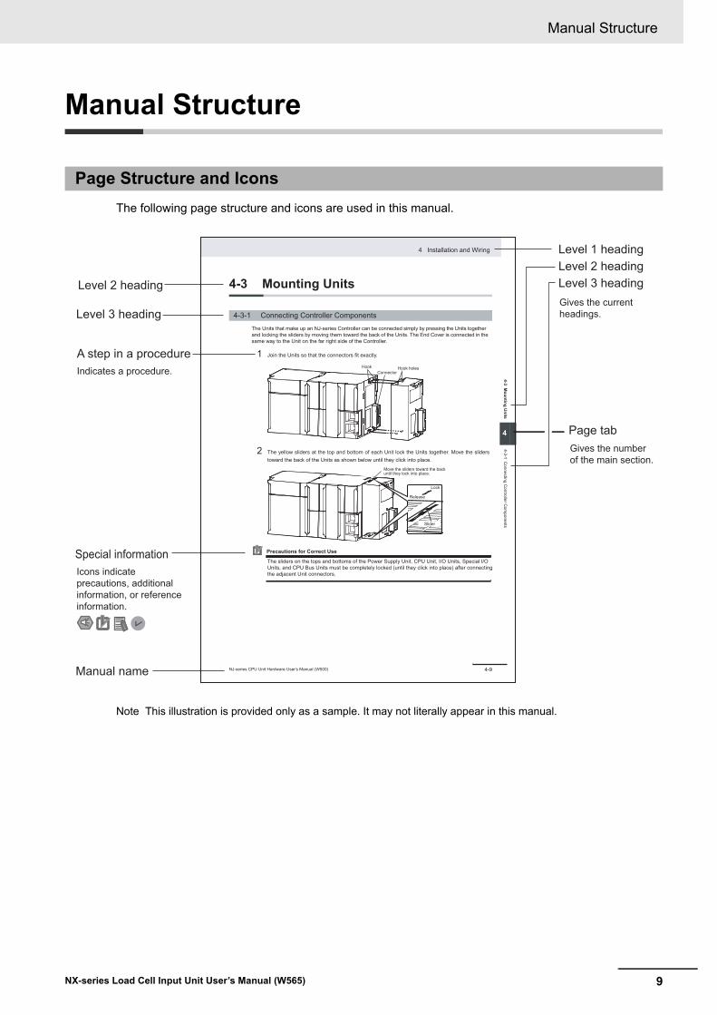
The following page structure and icons are used in this manual.
Note This illustration is provided only as a sample. It may not literally appear in this manual.
Page Structure and Icons
4-9
4 Installation and Wiring
NJ-series CPU Unit Hardware User’s Manual (W500)
stin
U gn
itnu
oM
3-4
4
stne
nop
moC r
ellort
noC
gnit
cenn
oC
1-3-
4
4-3 Mounting Units
The Units that make up an NJ-series Controller can be connected simply by pressing the Units togetherand locking the sliders by moving them toward the back of the Units. The End Cover is connected in thesame way to the Unit on the far right side of the Controller.
1 Join the Units so that the connectors fit exactly.
2 The yellow sliders at the top and bottom of each Unit lock the Units together. Move the sliderstoward the back of the Units as shown below until they click into place.
Precautions for Correct Use
4-3-1 Connecting Controller Components
ConnectorHook Hook holes
Slider
Lock
Release
Move the sliders toward the back until they lock into place.
Level 1 headingLevel 2 headingLevel 3 headingLevel 2 heading
A step in a procedure
Manual name
Special information
Level 3 heading
Page tab
Gives the current headings.
Indicates a procedure.
Icons indicate precautions, additional information, or reference information.
Gives the number of the main section.
The sliders on the tops and bottoms of the Power Supply Unit, CPU Unit, I/O Units, Special I/O Units, and CPU Bus Units must be completely locked (until they click into place) after connecting the adjacent Unit connectors.
Manual Structure
10 NX-series Load Cell Input Unit User’s Manual (W565)
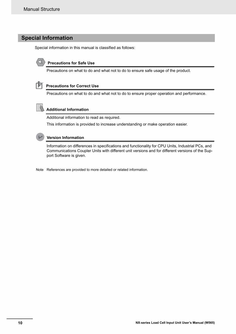
Special information in this manual is classified as follows:
Precautions for Safe Use
Precautions on what to do and what not to do to ensure safe usage of the product.
Precautions for Correct Use
Precautions on what to do and what not to do to ensure proper operation and performance.
Additional Information
Additional information to read as required.
This information is provided to increase understanding or make operation easier.
Version Information
Information on differences in specifications and functionality for CPU Units, Industrial PCs, and Communications Coupler Units with different unit versions and for different versions of the Sup-port Software is given.
Note References are provided to more detailed or related information.
Special Information
11
Manual Structure
NX-series Load Cell Input Unit User’s Manual (W565)
• In this manual, “download” refers to transferring data from the Support Software to a physical device and “upload” refers to transferring data from a physical device to the Support Software.
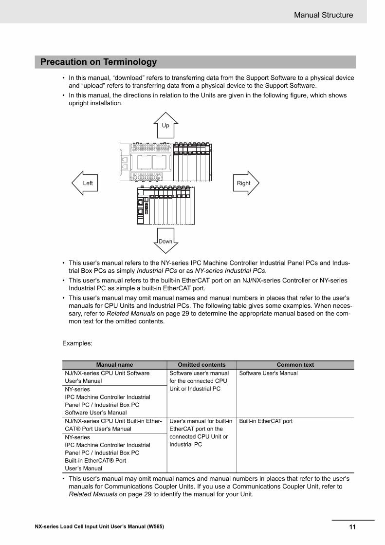
• In this manual, the directions in relation to the Units are given in the following figure, which shows upright installation.
• This user's manual refers to the NY-series IPC Machine Controller Industrial Panel PCs and Indus-trial Box PCs as simply Industrial PCs or as NY-series Industrial PCs.
• This user's manual refers to the built-in EtherCAT port on an NJ/NX-series Controller or NY-series Industrial PC as simple a built-in EtherCAT port.
• This user's manual may omit manual names and manual numbers in places that refer to the user's manuals for CPU Units and Industrial PCs. The following table gives some examples. When neces-sary, refer to Related Manuals on page 29 to determine the appropriate manual based on the com-mon text for the omitted contents.
Examples:
• This user's manual may omit manual names and manual numbers in places that refer to the user's manuals for Communications Coupler Units. If you use a Communications Coupler Unit, refer to Related Manuals on page 29 to identify the manual for your Unit.
Precaution on Terminology
Manual name Omitted contents Common text
NJ/NX-series CPU Unit Software User's Manual
Software user's manual for the connected CPU Unit or Industrial PC
Software User's Manual
NY-series IPC Machine Controller Industrial Panel PC / Industrial Box PCSoftware User’s Manual
NJ/NX-series CPU Unit Built-in Ether-CAT® Port User's Manual
User's manual for built-in EtherCAT port on the connected CPU Unit or Industrial PC
Built-in EtherCAT port
NY-seriesIPC Machine Controller Industrial Panel PC / Industrial Box PCBuilt-in EtherCAT® PortUser’s Manual
RightLeft
Up
Down
Terms and Conditions Agreement
12 NX-series Load Cell Input Unit User’s Manual (W565)
Terms and Conditions Agreement
Exclusive Warranty
Omron’s exclusive warranty is that the Products will be free from defects in materials and workman-ship for a period of twelve months from the date of sale by Omron (or such other period expressed in writing by Omron). Omron disclaims all other warranties, express or implied.
Limitations
OMRON MAKES NO WARRANTY OR REPRESENTATION, EXPRESS OR IMPLIED, ABOUT NON-INFRINGEMENT, MERCHANTABILITY OR FITNESS FOR A PARTICULAR PURPOSE OF THE PRODUCTS. BUYER ACKNOWLEDGES THAT IT ALONE HAS DETERMINED THAT THE PRODUCTS WILL SUITABLY MEET THE REQUIREMENTS OF THEIR INTENDED USE.
Omron further disclaims all warranties and responsibility of any type for claims or expenses based on infringement by the Products or otherwise of any intellectual property right.
Buyer Remedy
Omron’s sole obligation hereunder shall be, at Omron’s election, to (i) replace (in the form originally shipped with Buyer responsible for labor charges for removal or replacement thereof) the non-com-plying Product, (ii) repair the non-complying Product, or (iii) repay or credit Buyer an amount equal to the purchase price of the non-complying Product; provided that in no event shall Omron be responsible for warranty, repair, indemnity or any other claims or expenses regarding the Products unless Omron’s analysis confirms that the Products were properly handled, stored, installed and maintained and not subject to contamination, abuse, misuse or inappropriate modification. Return of any Products by Buyer must be approved in writing by Omron before shipment. Omron Companies shall not be liable for the suitability or unsuitability or the results from the use of Products in combi-nation with any electrical or electronic components, circuits, system assemblies or any other materi-als or substances or environments. Any advice, recommendations or information given orally or in writing, are not to be construed as an amendment or addition to the above warranty.
See http://www.omron.com/global/ or contact your Omron representative for published information.
OMRON COMPANIES SHALL NOT BE LIABLE FOR SPECIAL, INDIRECT, INCIDENTAL, OR CON-SEQUENTIAL DAMAGES, LOSS OF PROFITS OR PRODUCTION OR COMMERCIAL LOSS IN ANY WAY CONNECTED WITH THE PRODUCTS, WHETHER SUCH CLAIM IS BASED IN CONTRACT, WARRANTY, NEGLIGENCE OR STRICT LIABILITY.
Further, in no event shall liability of Omron Companies exceed the individual price of the Product on which liability is asserted.
Warranty, Limitations of Liability
Warranties
Limitation on Liability; Etc
13
Terms and Conditions Agreement
NX-series Load Cell Input Unit User’s Manual (W565)
Omron Companies shall not be responsible for conformity with any standards, codes or regulations which apply to the combination of the Product in the Buyer’s application or use of the Product. At Buyer’s request, Omron will provide applicable third party certification documents identifying ratings and limitations of use which apply to the Product. This information by itself is not sufficient for a com-plete determination of the suitability of the Product in combination with the end product, machine, sys-tem, or other application or use. Buyer shall be solely responsible for determining appropriateness of the particular Product with respect to Buyer’s application, product or system. Buyer shall take applica-tion responsibility in all cases.
NEVER USE THE PRODUCT FOR AN APPLICATION INVOLVING SERIOUS RISK TO LIFE OR PROPERTY OR IN LARGE QUANTITIES WITHOUT ENSURING THAT THE SYSTEM AS A WHOLE HAS BEEN DESIGNED TO ADDRESS THE RISKS, AND THAT THE OMRON PRODUCT(S) IS PROPERLY RATED AND INSTALLED FOR THE INTENDED USE WITHIN THE OVERALL EQUIP-MENT OR SYSTEM.
Omron Companies shall not be responsible for the user’s programming of a programmable Product, or any consequence thereof.
Data presented in Omron Company websites, catalogs and other materials is provided as a guide for the user in determining suitability and does not constitute a warranty. It may represent the result of Omron’s test conditions, and the user must correlate it to actual application requirements. Actual perfor-mance is subject to the Omron’s Warranty and Limitations of Liability.
Product specifications and accessories may be changed at any time based on improvements and other reasons. It is our practice to change part numbers when published ratings or features are changed, or when significant construction changes are made. However, some specifications of the Product may be changed without any notice. When in doubt, special part numbers may be assigned to fix or establish key specifications for your application. Please consult with your Omron’s representative at any time to confirm actual specifications of purchased Product.
Information presented by Omron Companies has been checked and is believed to be accurate; how-ever, no responsibility is assumed for clerical, typographical or proofreading errors or omissions.
Application Considerations
Suitability of Use
Programmable Products
Disclaimers
Performance Data
Change in Specifications
Errors and Omissions
Safety Precautions
14 NX-series Load Cell Input Unit User’s Manual (W565)
Safety Precautions
The following notation is used in this manual to provide precautions required to ensure safe usage of an NX-series Load Cell Input Unit.
The safety precautions that are provided are extremely important to safety. Always read and heed the information provided in all safety precautions.
The following notation is used.
Definition of Precautionary Information
Symbols
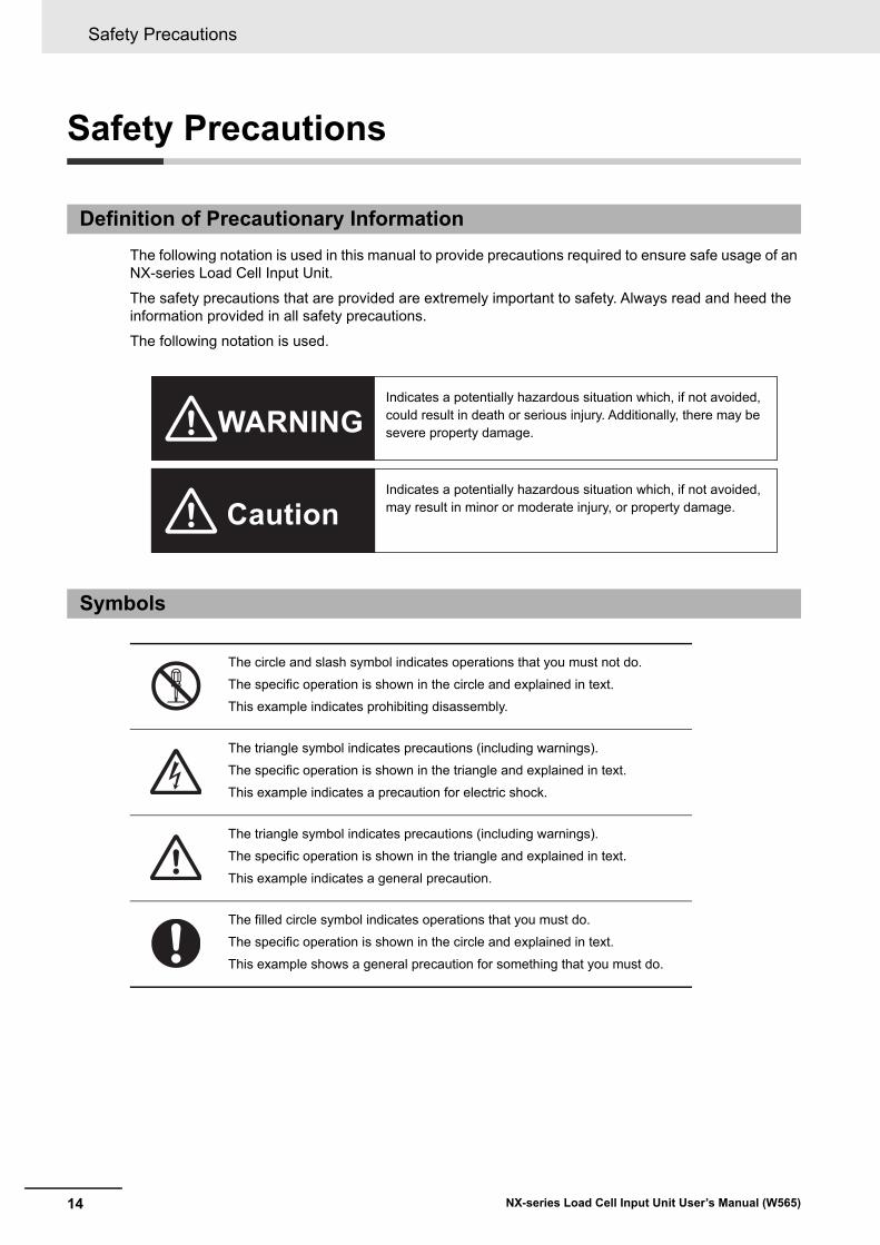
The circle and slash symbol indicates operations that you must not do.
The specific operation is shown in the circle and explained in text.
This example indicates prohibiting disassembly.
The triangle symbol indicates precautions (including warnings).
The specific operation is shown in the triangle and explained in text.
This example indicates a precaution for electric shock.
The triangle symbol indicates precautions (including warnings).
The specific operation is shown in the triangle and explained in text.
This example indicates a general precaution.
The filled circle symbol indicates operations that you must do.
The specific operation is shown in the circle and explained in text.
This example shows a general precaution for something that you must do.
WARNING
Caution
Indicates a potentially hazardous situation which, if not avoided, could result in death or serious injury. Additionally, there may be severe property damage.
Indicates a potentially hazardous situation which, if not avoided, may result in minor or moderate injury, or property damage.
15
Safety Precautions
NX-series Load Cell Input Unit User’s Manual (W565)
Warnings
During Power Supply
Do not touch the terminal section while power is ON.
Electric shock may occur.
Do not attempt to take any Unit apart.
In particular, high-voltage parts are present in Units that supply power while power is sup-plied or immediately after power is turned OFF. Touching any of these parts may result in electric shock. There are sharp parts inside the Unit that may cause injury.
Fail-safe Measures
Provide safety measures in external circuits to ensure safety in the system if an abnormality occurs due to malfunction of the CPU Unit, Industrial PCs, other Units, or slaves or due to other external factors affecting operation.
Not doing so may result in serious accidents due to incorrect operation.
Emergency stop circuits, interlock circuits, limit circuits, and similar safety measures must be provided in external control circuits.
The CPU Unit or Industrial PCs will turn OFF all outputs from Output Units in the following cases. The remote I/O slaves will operate according to the settings in the slaves.
• If a power supply error occurs.
• If the power supply connection becomes faulty.
• If a CPU watchdog timer error or CPU reset occurs.
• If a Controller error in the major fault level occurs.
• While the CPU Unit is on standby until RUN mode is entered after the power is turned ON
External safety measures must be provided to ensure safe operation of the system in such cases.
The outputs may remain ON or OFF due to deposition or burning of the output relays or destruction of the output transistors. As a countermeasure for such problems, external safety measures must be provided to ensure safe operation of the system.
If external power supplies for slaves or other devices are overloaded or short-circuited, the voltage will drop, outputs will turn OFF, and the system may be unable to read inputs. Pro-vide external safety measures in control with monitoring of external power supply voltage as required so that the system operates safely in such a case.
You must take fail-safe measures to ensure safety in the event of incorrect, missing, or abnormal signals caused by broken signal lines, momentary power interruptions, or other causes.
Not doing so may result in serious accidents due to incorrect operation.
WARNING
Safety Precautions
16 NX-series Load Cell Input Unit User’s Manual (W565)
Voltage and Current Inputs
Make sure that the voltages and currents that are input to the Units and slaves are within the specified ranges.
Inputting voltages or currents that are outside of the specified ranges may cause accidents or fire.
Transferring
Always confirm safety at the destination node before you transfer Unit configuration infor-mation, parameters, settings, or other data from tools such as the Sysmac Studio.
The devices or machines may operate unexpectedly, regardless of the operating mode of the Controller.
Cautions
Wiring
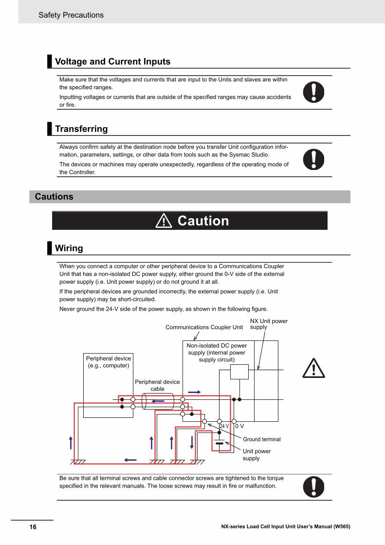
When you connect a computer or other peripheral device to a Communications Coupler Unit that has a non-isolated DC power supply, either ground the 0-V side of the external power supply (i.e. Unit power supply) or do not ground it at all.
If the peripheral devices are grounded incorrectly, the external power supply (i.e. Unit power supply) may be short-circuited.
Never ground the 24-V side of the power supply, as shown in the following figure.
Be sure that all terminal screws and cable connector screws are tightened to the torque specified in the relevant manuals. The loose screws may result in fire or malfunction.
Caution
Peripheral device (e.g., computer)
Non-isolated DC power supply (internal power
supply circuit)
24 V 0 V
Peripheral device cable
Ground terminal
Communications Coupler UnitNX Unit power supply
Unit power supply
17
Safety Precautions
NX-series Load Cell Input Unit User’s Manual (W565)
Online Editing
Execute online editing only after confirming that no adverse effects will be caused by devia-tions in the timing of I/O. If you perform online editing, the task execution time may exceed the task period, I/O may not be refreshed with external devices, input signals may not be read, and output timing may change.
Precautions for Safe Use
18 NX-series Load Cell Input Unit User’s Manual (W565)
Precautions for Safe Use
• When transporting any Unit, use the special packing box for it.Also, do not subject the Unit to excessive vibration or shock during transportation.
• Do not drop any Unit or subject it to abnormal vibration or shock.Doing so may result in Unit malfunction or burning.
• Mount terminal blocks and connectors only after checking the mounting location carefully.
• Be sure that the terminal blocks, expansion cables, and other items with locking devices are properly locked into place.
• Always turn OFF the power supply before installing the Unit. If the power supply is not OFF, the Unit may malfunction or may be damaged.
• Always turn OFF the Unit power supply and I/O power supply before you remove the NX Unit.
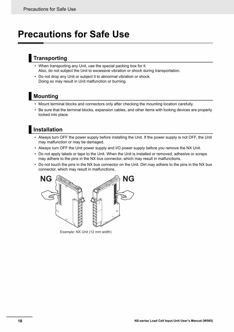
• Do not apply labels or tape to the Unit. When the Unit is installed or removed, adhesive or scraps may adhere to the pins in the NX bus connector, which may result in malfunctions.
• Do not touch the pins in the NX bus connector on the Unit. Dirt may adhere to the pins in the NX bus connector, which may result in malfunctions.
Transporting
Mounting
Installation
Example: NX Unit (12 mm width)
NG NG
19
Precautions for Safe Use
NX-series Load Cell Input Unit User’s Manual (W565)
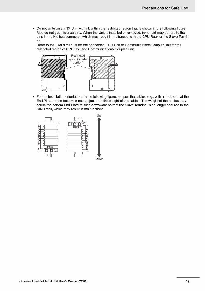
• Do not write on an NX Unit with ink within the restricted region that is shown in the following figure. Also do not get this area dirty. When the Unit is installed or removed, ink or dirt may adhere to the pins in the NX bus connector, which may result in malfunctions in the CPU Rack or the Slave Termi-nal.Refer to the user’s manual for the connected CPU Unit or Communications Coupler Unit for the restricted region of CPU Unit and Communications Coupler Unit.
• For the installation orientations in the following figure, support the cables, e.g., with a duct, so that the End Plate on the bottom is not subjected to the weight of the cables. The weight of the cables may cause the bottom End Plate to slide downward so that the Slave Terminal is no longer secured to the DIN Track, which may result in malfunctions.
Restricted region (shaded
portion)
Up
Down
Precautions for Safe Use
20 NX-series Load Cell Input Unit User’s Manual (W565)
• Double-check all switches and other settings and double-check all wiring to make sure that they are correct before turning ON the power supply.Use the correct wiring parts and tools when you wire the system.
• Do not pull on the cables or bend the cables beyond their natural limit. Also, do not place heavy objects on top of the cables or other wiring lines. Doing so may break the cable.
• When wiring or installing the Units, do not allow metal fragments to enter the Units.
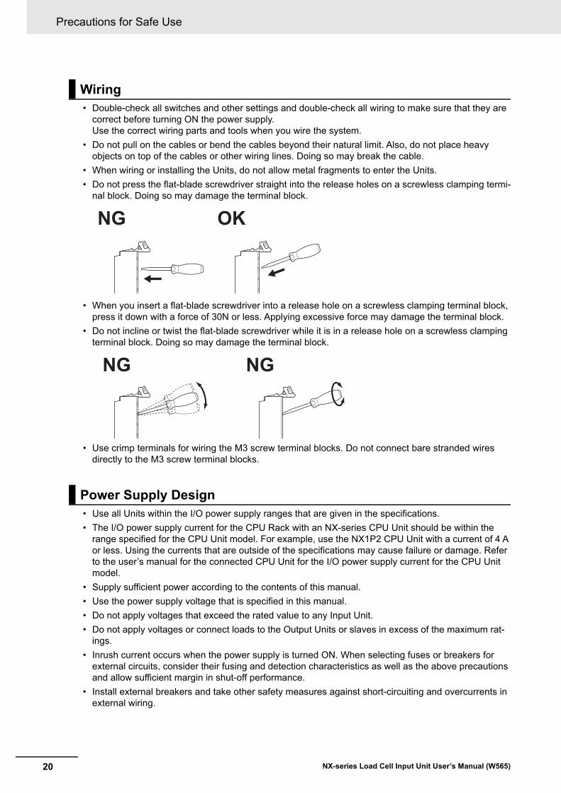
• Do not press the flat-blade screwdriver straight into the release holes on a screwless clamping termi-nal block. Doing so may damage the terminal block.
• When you insert a flat-blade screwdriver into a release hole on a screwless clamping terminal block, press it down with a force of 30N or less. Applying excessive force may damage the terminal block.
• Do not incline or twist the flat-blade screwdriver while it is in a release hole on a screwless clamping terminal block. Doing so may damage the terminal block.
• Use crimp terminals for wiring the M3 screw terminal blocks. Do not connect bare stranded wires directly to the M3 screw terminal blocks.
• Use all Units within the I/O power supply ranges that are given in the specifications.
• The I/O power supply current for the CPU Rack with an NX-series CPU Unit should be within the range specified for the CPU Unit model. For example, use the NX1P2 CPU Unit with a current of 4 A or less. Using the currents that are outside of the specifications may cause failure or damage. Refer to the user’s manual for the connected CPU Unit for the I/O power supply current for the CPU Unit model.
• Supply sufficient power according to the contents of this manual.
• Use the power supply voltage that is specified in this manual.
• Do not apply voltages that exceed the rated value to any Input Unit.
• Do not apply voltages or connect loads to the Output Units or slaves in excess of the maximum rat-ings.
• Inrush current occurs when the power supply is turned ON. When selecting fuses or breakers for external circuits, consider their fusing and detection characteristics as well as the above precautions and allow sufficient margin in shut-off performance.
• Install external breakers and take other safety measures against short-circuiting and overcurrents in external wiring.
Wiring
Power Supply Design
NG OK
NG NG
21
Precautions for Safe Use
NX-series Load Cell Input Unit User’s Manual (W565)
• When you set the Operating Mode at Startup, confirm that no adverse effect will occur in the system.
• Before you start operation, always register the NX Units that are connected to the Communications Coupler Unit in the host communications master as the Unit Configuration Information.
• Check the user program, data, and parameter settings for proper execution before you use them for actual operation.
• If you change the fail-soft operation setting, the output status when the error occurs may also change. Confirm safety before you change the fail-soft operation setting.
• If you use fail-soft operation, write programming to determine whether Unit I/O data is valid. Without such programming, the user program cannot distinguish between Units for which I/O refreshing is continued and Units for which I/O refreshing is stopped.
• Do not disconnect the cable or turn OFF the power supply to the Controller or a Slave Terminal when downloading data or the user program from the Support Software.
• Always turn OFF the external power supply to the Units before attempting any of the following.
Mounting or removing an NX Unit, Communications Coupler Unit, CPU Unit, or Industrial PC Assembling UnitsSetting DIP switches or rotary switchesConnecting or wiring cablesAttaching or removing terminal blocks or connectors
Units that supply power continue to supply power to the Units for up to several seconds after the power supply is turned OFF. The PWR indicator remains lit as long as power is supplied. Confirm that the PWR indicator is not lit before you perform any of the above.
• Confirm that the controlled system will not be adversely affected before you perform any of the fol-lowing operations.
Changing the operating mode of the CPU Unit or the Industrial PC (including changing the setting of the Operating Mode at Startup)Changing the user program or settingsChanging set values or present valuesForced refreshing
• Always sufficiently check the safety at the connected devices before you change the settings of a slave or Unit.
• Do not exceed the ranges that are given in the specifications for the communications distance and number of connected Units.
• Refer to the user’s manual for the Communications Coupler Unit for precautions for the safe use of communications with the connected Communications Coupler Unit.
Turning ON the Power Supply
Actual Operation
Turning OFF the Power Supply
Operation
General Communications
Precautions for Safe Use
22 NX-series Load Cell Input Unit User’s Manual (W565)
• When you replace a Unit, start operation only after you transfer the settings and variables that are required for operation to the new Unit.
• Dispose of the product according to local ordinances as they apply.
Unit Replacement
Disposal
23
Precautions for Correct Use
NX-series Load Cell Input Unit User’s Manual (W565)
Precautions for Correct Use
• Follow the instructions in this manual to correctly perform installation and wiring.
• Do not operate or store the Units in the following locations. Doing so may result in malfunction, in operation stopping, or in burning.
Locations subject to direct sunlightLocations subject to temperatures or humidity outside the range specified in the specificationsLocations subject to condensation as the result of severe changes in temperatureLocations subject to corrosive or flammable gasesLocations subject to dust (especially iron dust) or saltsLocations subject to exposure to water, oil, or chemicalsLocations subject to shock or vibration
• Take appropriate and sufficient countermeasures during installation in the following locations.
Locations subject to strong, high-frequency noiseLocations subject to static electricity or other forms of noiseLocations subject to strong electromagnetic fieldsLocations subject to possible exposure to radioactivityLocations close to power lines
• Before touching a Unit, be sure to first touch a grounded metallic object in order to discharge any static build-up.
• Use the rated power supply voltage for the Units that supply power. Take appropriate measures to ensure that the specified power with the rated voltage and frequency is supplied in places where the power supply is unstable.
• Install the Units away from sources of heat and ensure proper ventilation. Not doing so may result in malfunction, in operation stopping, or in burning.
• Do not allow foreign matter to enter the openings in the Unit. Doing so may result in Unit burning, electric shock, or failure.
• If you change the event level of an error, the output status when the error occurs may also change. Confirm safety before you change an event level.
• Do not turn OFF the power supply while data is being transferred.
• Do not turn OFF the power supply while parameters are being written to the CPU Unit, the Communi-cations Coupler Unit or NX Units.
• Refer to the user’s manual for the Communications Coupler Unit for precautions for the correct use of communications with the connected Communications Coupler Unit.
Storage, Mounting, and Wiring
Actual Operation
Turning OFF the Power Supply
General Communications
Regulations and Standards
24 NX-series Load Cell Input Unit User’s Manual (W565)
Regulations and Standards
• EMC Directives
• Low Voltage Directive
EMC Directives
OMRON devices that comply with EU Directives also conform to the related EMC standards so that they can be more easily built into other devices or the overall machine. The actual products have been checked for conformity to EMC standards.*1
Whether the products conform to the standards in the system used by the customer, however, must be checked by the customer. EMC-related performance of the OMRON devices that comply with EU Directives will vary depending on the configuration, wiring, and other conditions of the equipment or control panel on which the OMRON devices are installed. The customer must, therefore, perform the final check to confirm that devices and the overall machine conform to EMC standards.
*1. Applicable EMC (Electromagnetic Compatibility) standards are as follows:EMS (Electromagnetic Susceptibility): EN 61131-2EMI (Electromagnetic Interference): EN 61131-2 (Radiated emission: 10-m regulations).
Low Voltage Directive
Always ensure that devices operating at voltages of 50 to 1,000 VAC and 75 to 1,500 VDC meet the required safety standards. The applicable directive is EN 61010-2-201.
Conformance to EU Directives
The NX-series Units comply with EU Directives. To ensure that the machine or device in which the NX-series Units are used complies with EU Directives, the following precautions must be observed.
• The NX-series Units must be installed within a control panel.
• You must use SELV power supply for the DC power supplies that are connected as the Unit power supplies and I/O power supplies for the NX-series Units. EMC standard compliance was confirmed for the recommended Power Supplies. Refer to the user’s manual for the connected CPU Unit for the recommended power supplies for the CPU Rack with an NX-series CPU Unit. Refer to the user’s manual for the connected Communications Coupler Unit for the recommended power supplies for the Slave Terminal.
• NX-series Units that comply with EU Directives also conform to the Common Emission Standard (EN 61131-2). Radiated emission characteristics (10-m regulations) may vary depending on the configuration of the control panel used, other devices connected to the control panel, wiring, and other conditions.
You must therefore confirm that the overall machine or equipment in which the NX-series Units are used complies with EU Directives.
• You must use power supplies with an output hold time of 10 ms or longer for the DC power sup-plies that are connected as the Unit power supplies and I/O power supplies for the NX-series Units.
Conformance to EU Directives
Applicable Directives
Concepts
25
Regulations and Standards
NX-series Load Cell Input Unit User’s Manual (W565)
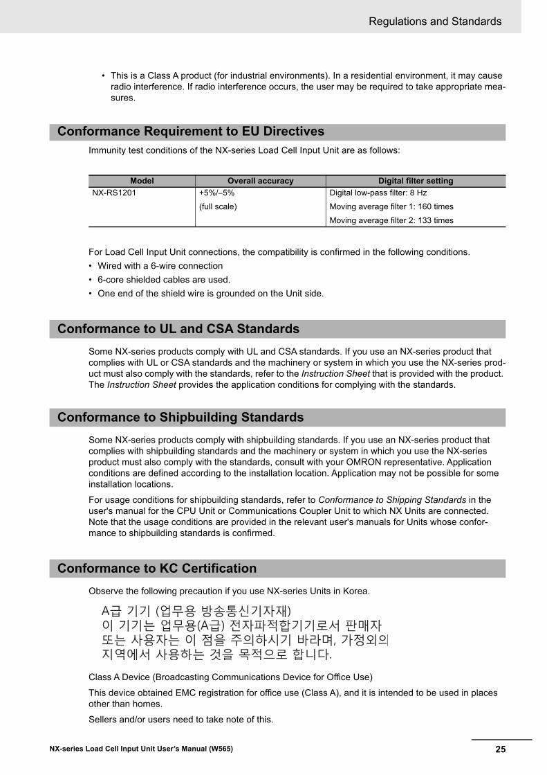
• This is a Class A product (for industrial environments). In a residential environment, it may cause radio interference. If radio interference occurs, the user may be required to take appropriate mea-sures.
Immunity test conditions of the NX-series Load Cell Input Unit are as follows:
For Load Cell Input Unit connections, the compatibility is confirmed in the following conditions.
• Wired with a 6-wire connection
• 6-core shielded cables are used.
• One end of the shield wire is grounded on the Unit side.
Some NX-series products comply with UL and CSA standards. If you use an NX-series product that complies with UL or CSA standards and the machinery or system in which you use the NX-series prod-uct must also comply with the standards, refer to the Instruction Sheet that is provided with the product. The Instruction Sheet provides the application conditions for complying with the standards.
Some NX-series products comply with shipbuilding standards. If you use an NX-series product that complies with shipbuilding standards and the machinery or system in which you use the NX-series product must also comply with the standards, consult with your OMRON representative. Application conditions are defined according to the installation location. Application may not be possible for some installation locations.
For usage conditions for shipbuilding standards, refer to Conformance to Shipping Standards in the user's manual for the CPU Unit or Communications Coupler Unit to which NX Units are connected. Note that the usage conditions are provided in the relevant user's manuals for Units whose confor-mance to shipbuilding standards is confirmed.
Observe the following precaution if you use NX-series Units in Korea.
Class A Device (Broadcasting Communications Device for Office Use)
This device obtained EMC registration for office use (Class A), and it is intended to be used in places other than homes.
Sellers and/or users need to take note of this.
Conformance Requirement to EU Directives
Model Overall accuracy Digital filter setting
NX-RS1201 +5%/5%
(full scale)
Digital low-pass filter: 8 Hz
Moving average filter 1: 160 times
Moving average filter 2: 133 times
Conformance to UL and CSA Standards
Conformance to Shipbuilding Standards
Conformance to KC Certification

Regulations and Standards
26 NX-series Load Cell Input Unit User’s Manual (W565)
This product incorporates certain third party software. The license and copyright information associated with this software is available at http://www.fa.omron.co.jp/nj_info_e/.
Software Licenses and Copyrights
27
Unit Versions
NX-series Load Cell Input Unit User’s Manual (W565)
Unit Versions
This section describes the notation that is used for unit versions, the confirmation method for unit ver-sions, and the relationship between unit versions and Support Software versions.
A “unit version” has been introduced to manage the Units in the NX Series according to differences in functionality accompanying Unit upgrades.
An example is provided below for Communications Coupler Units and NX Units. For the notation that is used for the unit versions of CPU Units or Industrial PCs and the confirmation method for unit versions, refer to the user's manual for each Unit.
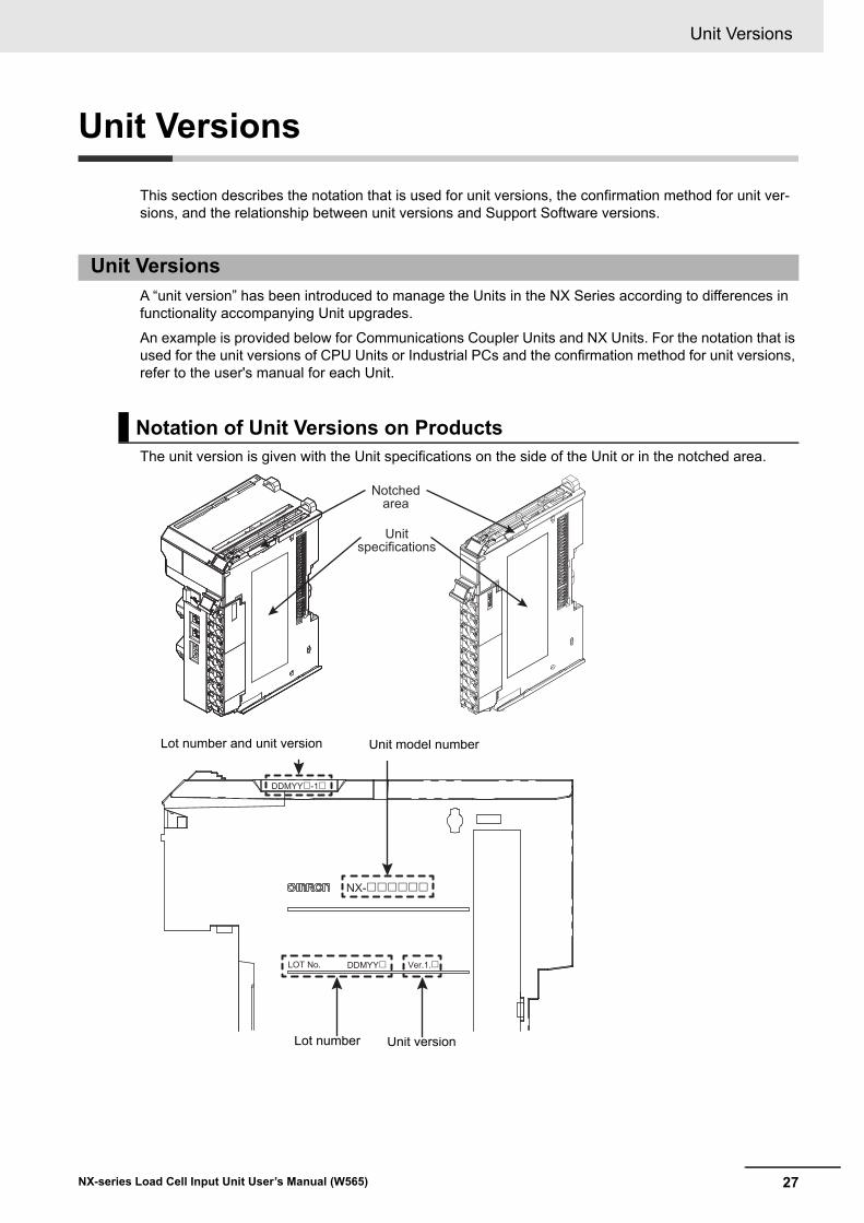
The unit version is given with the Unit specifications on the side of the Unit or in the notched area.
Unit Versions
Notation of Unit Versions on Products
Notched area
Unit specifications
LOT No.
Unit versionLot number
Unit model numberLot number and unit version
Unit Versions
28 NX-series Load Cell Input Unit User’s Manual (W565)
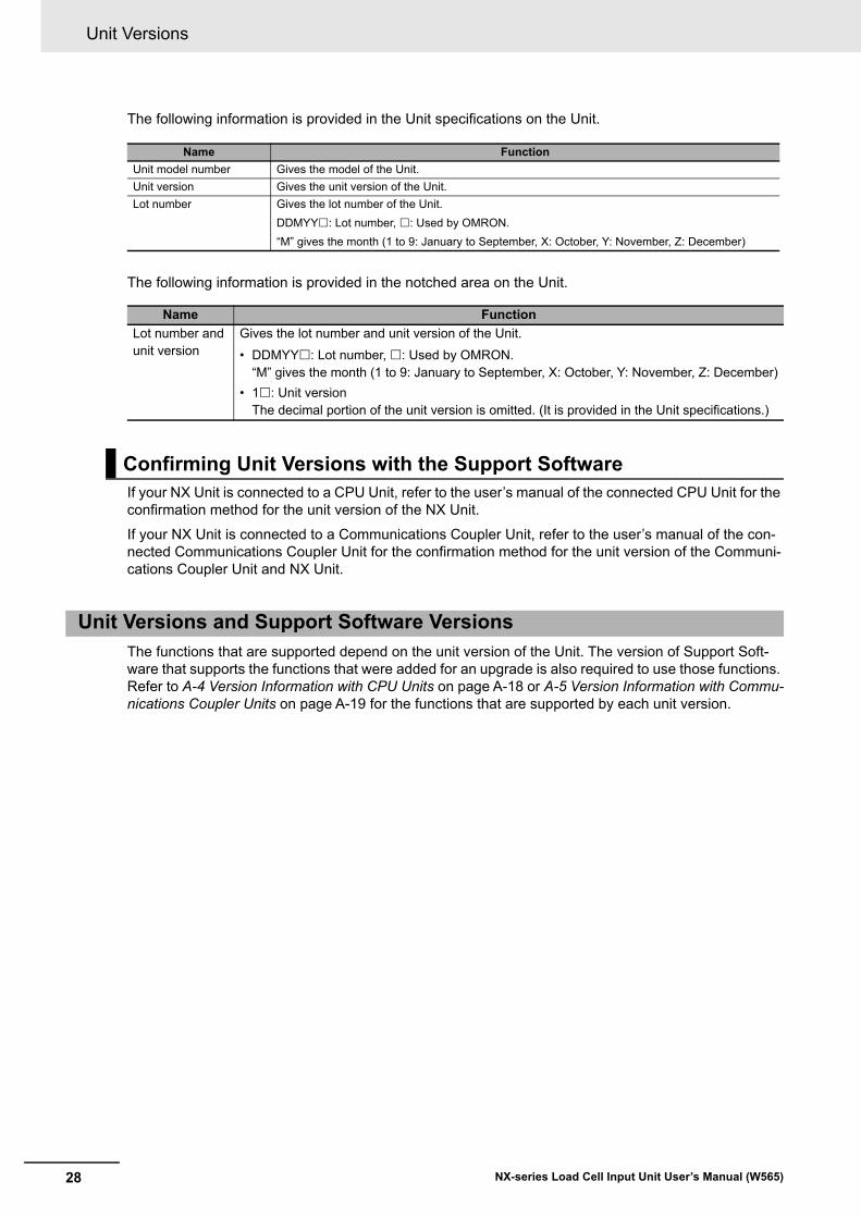
The following information is provided in the Unit specifications on the Unit.
The following information is provided in the notched area on the Unit.
If your NX Unit is connected to a CPU Unit, refer to the user’s manual of the connected CPU Unit for the confirmation method for the unit version of the NX Unit.
If your NX Unit is connected to a Communications Coupler Unit, refer to the user’s manual of the con-nected Communications Coupler Unit for the confirmation method for the unit version of the Communi-cations Coupler Unit and NX Unit.
The functions that are supported depend on the unit version of the Unit. The version of Support Soft-ware that supports the functions that were added for an upgrade is also required to use those functions. Refer to A-4 Version Information with CPU Units on page A-18 or A-5 Version Information with Commu-nications Coupler Units on page A-19 for the functions that are supported by each unit version.
Name Function
Unit model number Gives the model of the Unit.
Unit version Gives the unit version of the Unit.
Lot number Gives the lot number of the Unit.
DDMYY: Lot number, : Used by OMRON.
“M” gives the month (1 to 9: January to September, X: October, Y: November, Z: December)
Name Function
Lot number and unit version
Gives the lot number and unit version of the Unit.
• DDMYY: Lot number, : Used by OMRON.“M” gives the month (1 to 9: January to September, X: October, Y: November, Z: December)
• 1: Unit versionThe decimal portion of the unit version is omitted. (It is provided in the Unit specifications.)
Confirming Unit Versions with the Support Software
Unit Versions and Support Software Versions
29
Related Manuals
NX-series Load Cell Input Unit User’s Manual (W565)
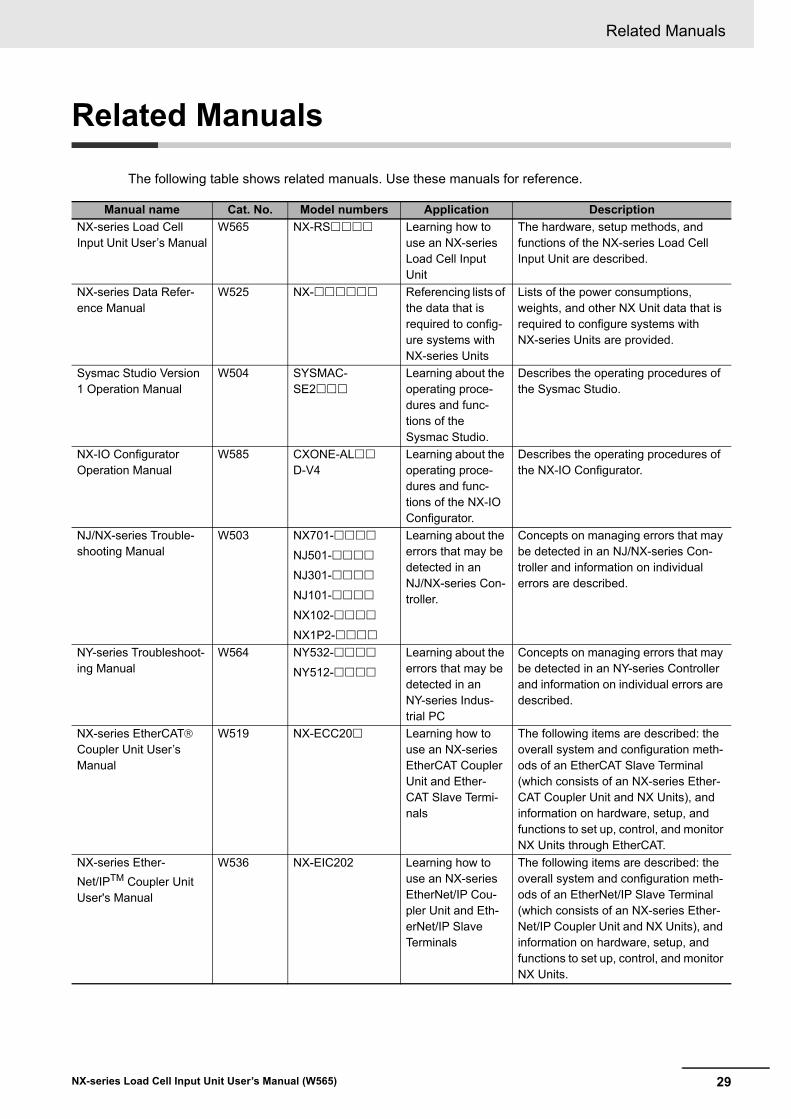
Related Manuals
The following table shows related manuals. Use these manuals for reference.
Manual name Cat. No. Model numbers Application Description
NX-series Load Cell Input Unit User’s Manual
W565 NX-RS Learning how to use an NX-series Load Cell Input Unit
The hardware, setup methods, and functions of the NX-series Load Cell Input Unit are described.
NX-series Data Refer-ence Manual
W525 NX- Referencing lists of the data that is required to config-ure systems with NX-series Units
Lists of the power consumptions, weights, and other NX Unit data that is required to configure systems with NX-series Units are provided.
Sysmac Studio Version 1 Operation Manual
W504 SYSMAC-SE2
Learning about the operating proce-dures and func-tions of the Sysmac Studio.
Describes the operating procedures of the Sysmac Studio.
NX-IO Configurator Operation Manual
W585 CXONE-AL D-V4
Learning about the operating proce-dures and func-tions of the NX-IO Configurator.
Describes the operating procedures of the NX-IO Configurator.
NJ/NX-series Trouble-shooting Manual
W503 NX701-
NJ501-
NJ301-
NJ101-
NX102-
NX1P2-
Learning about the errors that may be detected in an NJ/NX-series Con-troller.
Concepts on managing errors that may be detected in an NJ/NX-series Con-troller and information on individual errors are described.
NY-series Troubleshoot-ing Manual
W564 NY532-
NY512-
Learning about the errors that may be detected in an NY-series Indus-trial PC
Concepts on managing errors that may be detected in an NY-series Controller and information on individual errors are described.
NX-series EtherCAT Coupler Unit User’s Manual
W519 NX-ECC20 Learning how to use an NX-series EtherCAT Coupler Unit and Ether-CAT Slave Termi-nals
The following items are described: the overall system and configuration meth-ods of an EtherCAT Slave Terminal (which consists of an NX-series Ether-CAT Coupler Unit and NX Units), and information on hardware, setup, and functions to set up, control, and monitor NX Units through EtherCAT.
NX-series Ether-
Net/IPTM Coupler Unit User's Manual
W536 NX-EIC202 Learning how to use an NX-series EtherNet/IP Cou-pler Unit and Eth-erNet/IP Slave Terminals
The following items are described: the overall system and configuration meth-ods of an EtherNet/IP Slave Terminal (which consists of an NX-series Ether-Net/IP Coupler Unit and NX Units), and information on hardware, setup, and functions to set up, control, and monitor NX Units.
Related Manuals
30 NX-series Load Cell Input Unit User’s Manual (W565)
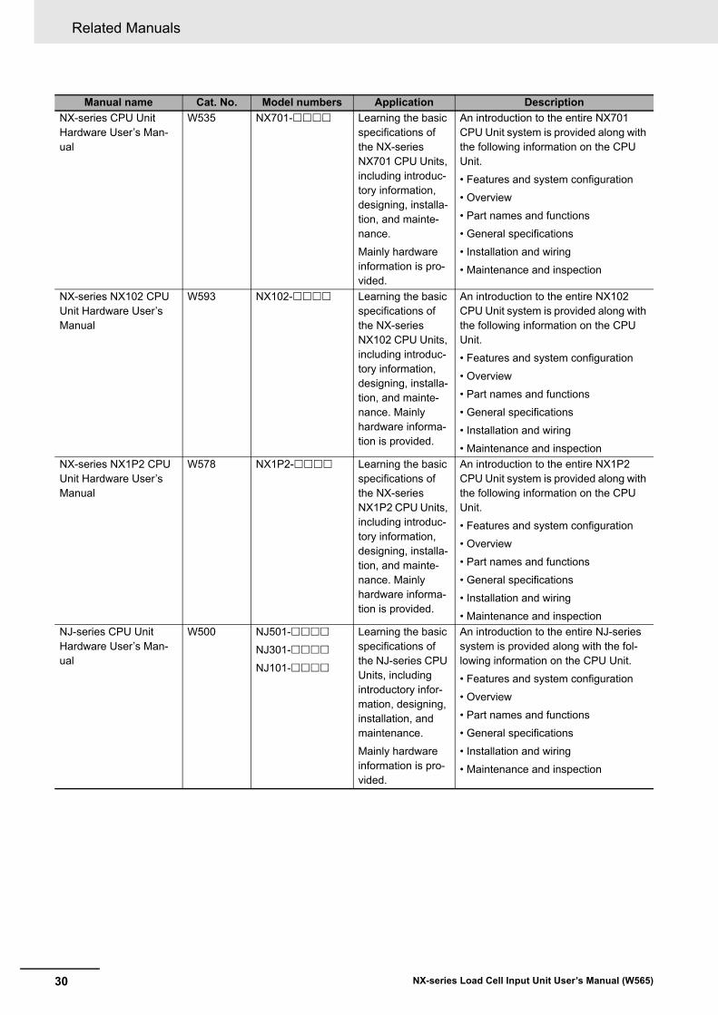
NX-series CPU Unit Hardware User’s Man-ual
W535 NX701- Learning the basic specifications of the NX-series NX701 CPU Units, including introduc-tory information, designing, installa-tion, and mainte-nance.
Mainly hardware information is pro-vided.
An introduction to the entire NX701 CPU Unit system is provided along with the following information on the CPU Unit.
• Features and system configuration
• Overview
• Part names and functions
• General specifications
• Installation and wiring
• Maintenance and inspection
NX-series NX102 CPU Unit Hardware User’s Manual
W593 NX102- Learning the basic specifications of the NX-series NX102 CPU Units, including introduc-tory information, designing, installa-tion, and mainte-nance. Mainly hardware informa-tion is provided.
An introduction to the entire NX102 CPU Unit system is provided along with the following information on the CPU Unit.
• Features and system configuration
• Overview
• Part names and functions
• General specifications
• Installation and wiring
• Maintenance and inspection
NX-series NX1P2 CPU Unit Hardware User’s Manual
W578 NX1P2- Learning the basic specifications of the NX-series NX1P2 CPU Units, including introduc-tory information, designing, installa-tion, and mainte-nance. Mainly hardware informa-tion is provided.
An introduction to the entire NX1P2 CPU Unit system is provided along with the following information on the CPU Unit.
• Features and system configuration
• Overview
• Part names and functions
• General specifications
• Installation and wiring
• Maintenance and inspection
NJ-series CPU Unit Hardware User’s Man-ual
W500 NJ501-
NJ301-
NJ101-
Learning the basic specifications of the NJ-series CPU Units, including introductory infor-mation, designing, installation, and maintenance.
Mainly hardware information is pro-vided.
An introduction to the entire NJ-series system is provided along with the fol-lowing information on the CPU Unit.
• Features and system configuration
• Overview
• Part names and functions
• General specifications
• Installation and wiring
• Maintenance and inspection
Manual name Cat. No. Model numbers Application Description
31
Related Manuals
NX-series Load Cell Input Unit User’s Manual (W565)
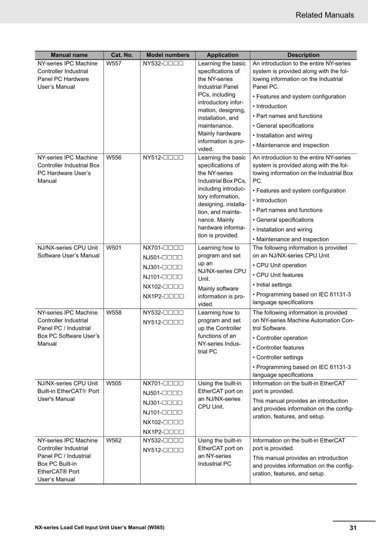
NY-series IPC Machine Controller Industrial Panel PC Hardware User’s Manual
W557 NY532- Learning the basic specifications of the NY-series Industrial Panel PCs, including introductory infor-mation, designing, installation, and maintenance. Mainly hardware information is pro-vided.
An introduction to the entire NY-series system is provided along with the fol-lowing information on the Industrial Panel PC.
• Features and system configuration
• Introduction
• Part names and functions
• General specifications
• Installation and wiring
• Maintenance and inspection
NY-series IPC Machine Controller Industrial Box PC Hardware User’s Manual
W556 NY512- Learning the basic specifications of the NY-series Industrial Box PCs, including introduc-tory information, designing, installa-tion, and mainte-nance. Mainly hardware informa-tion is provided.
An introduction to the entire NY-series system is provided along with the fol-lowing information on the Industrial Box PC.
• Features and system configuration
• Introduction
• Part names and functions
• General specifications
• Installation and wiring
• Maintenance and inspection
NJ/NX-series CPU Unit Software User’s Manual
W501 NX701-
NJ501-
NJ301-
NJ101-
NX102-
NX1P2-
Learning how to program and set up an NJ/NX-series CPU Unit.
Mainly software information is pro-vided.
The following information is provided on an NJ/NX-series CPU Unit.
• CPU Unit operation
• CPU Unit features
• Initial settings
• Programming based on IEC 61131-3 language specifications
NY-series IPC Machine Controller Industrial Panel PC / Industrial Box PC Software User’s Manual
W558 NY532-
NY512-
Learning how to program and set up the Controller functions of an NY-series Indus-trial PC
The following information is provided on NY-series Machine Automation Con-trol Software.
• Controller operation
• Controller features
• Controller settings
• Programming based on IEC 61131-3 language specifications
NJ/NX-series CPU Unit Built-in EtherCAT Port User's Manual
W505 NX701-
NJ501-
NJ301-
NJ101-
NX102-
NX1P2-
Using the built-in EtherCAT port on an NJ/NX-series CPU Unit.
Information on the built-in EtherCAT port is provided.
This manual provides an introduction and provides information on the config-uration, features, and setup.
NY-series IPC Machine Controller Industrial Panel PC / Industrial Box PC Built-in EtherCAT® Port User’s Manual
W562 NY532-
NY512-
Using the built-in EtherCAT port on an NY-series Industrial PC
Information on the built-in EtherCAT port is provided.
This manual provides an introduction and provides information on the config-uration, features, and setup.
Manual name Cat. No. Model numbers Application Description
Related Manuals
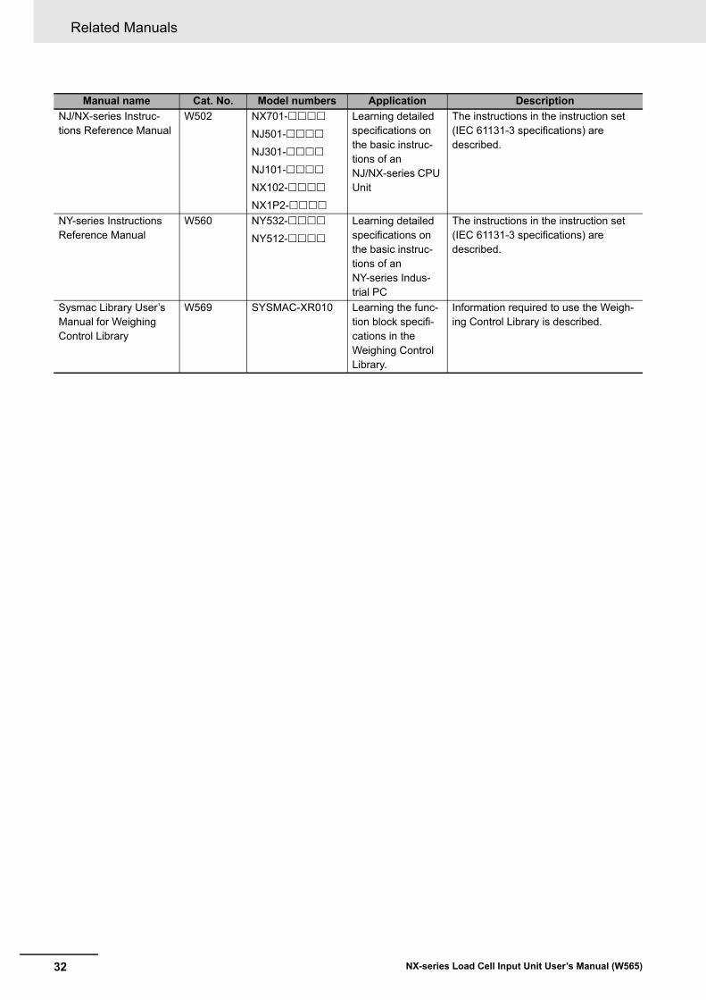
32 NX-series Load Cell Input Unit User’s Manual (W565)
NJ/NX-series Instruc-tions Reference Manual
W502 NX701-
NJ501-
NJ301-
NJ101-
NX102-
NX1P2-
Learning detailed specifications on the basic instruc-tions of an NJ/NX-series CPU Unit
The instructions in the instruction set (IEC 61131-3 specifications) are described.
NY-series Instructions Reference Manual
W560 NY532-
NY512-
Learning detailed specifications on the basic instruc-tions of an NY-series Indus-trial PC
The instructions in the instruction set (IEC 61131-3 specifications) are described.
Sysmac Library User’s Manual for Weighing Control Library
W569 SYSMAC-XR010 Learning the func-tion block specifi-cations in the Weighing Control Library.
Information required to use the Weigh-ing Control Library is described.
Manual name Cat. No. Model numbers Application Description
33
Terminology
NX-series Load Cell Input Unit User’s Manual (W565)
Terminology
TermAbbre-viation
Description
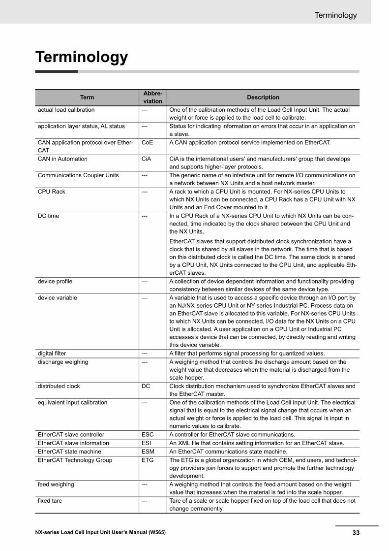
actual load calibration --- One of the calibration methods of the Load Cell Input Unit. The actual weight or force is applied to the load cell to calibrate.
application layer status, AL status --- Status for indicating information on errors that occur in an application on a slave.
CAN application protocol over Ether-CAT
CoE A CAN application protocol service implemented on EtherCAT.
CAN in Automation CiA CiA is the international users' and manufacturers' group that develops and supports higher-layer protocols.
Communications Coupler Units --- The generic name of an interface unit for remote I/O communications on a network between NX Units and a host network master.
CPU Rack --- A rack to which a CPU Unit is mounted. For NX-series CPU Units to which NX Units can be connected, a CPU Rack has a CPU Unit with NX Units and an End Cover mounted to it.
DC time --- In a CPU Rack of a NX-series CPU Unit to which NX Units can be con-nected, time indicated by the clock shared between the CPU Unit and the NX Units.
EtherCAT slaves that support distributed clock synchronization have a clock that is shared by all slaves in the network. The time that is based on this distributed clock is called the DC time. The same clock is shared by a CPU Unit, NX Units connected to the CPU Unit, and applicable Eth-erCAT slaves.
device profile --- A collection of device dependent information and functionality providing consistency between similar devices of the same device type.
device variable --- A variable that is used to access a specific device through an I/O port by an NJ/NX-series CPU Unit or NY-series Industrial PC. Process data on an EtherCAT slave is allocated to this variable. For NX-series CPU Units to which NX Units can be connected, I/O data for the NX Units on a CPU Unit is allocated. A user application on a CPU Unit or Industrial PC accesses a device that can be connected, by directly reading and writing this device variable.
digital filter --- A filter that performs signal processing for quantized values.
discharge weighing --- A weighing method that controls the discharge amount based on the weight value that decreases when the material is discharged from the scale hopper.
distributed clock DC Clock distribution mechanism used to synchronize EtherCAT slaves and the EtherCAT master.
equivalent input calibration --- One of the calibration methods of the Load Cell Input Unit. The electrical signal that is equal to the electrical signal change that occurs when an actual weight or force is applied to the load cell. This signal is input in numeric values to calibrate.
EtherCAT slave controller ESC A controller for EtherCAT slave communications.
EtherCAT slave information ESI An XML file that contains setting information for an EtherCAT slave.
EtherCAT state machine ESM An EtherCAT communications state machine.
EtherCAT Technology Group ETG The ETG is a global organization in which OEM, end users, and technol-ogy providers join forces to support and promote the further technology development.
feed weighing --- A weighing method that controls the feed amount based on the weight value that increases when the material is fed into the scale hopper.
fixed tare --- Tare of a scale or scale hopper fixed on top of the load cell that does not change permanently.
Terminology
34 NX-series Load Cell Input Unit User’s Manual (W565)
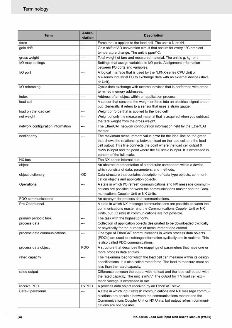
force --- Force that is applied to the load cell. The unit is N or kN.
gain drift --- Gain shift of AD conversion circuit that occurs for every 1°C ambient temperature change. The unit is ppm/°C.
gross weight --- Total weight of tare and measured material. The unit is g, kg, or t.
I/O map settings --- Settings that assign variables to I/O ports. Assignment information between I/O ports and variables.
I/O port --- A logical interface that is used by the NJ/NX-series CPU Unit or NY-series Industrial PC to exchange data with an external device (slave or Unit).
I/O refreshing --- Cyclic data exchange with external devices that is performed with prede-termined memory addresses.
index --- Address of an object within an application process.
load cell --- A sensor that converts the weight or force into an electrical signal to out-put. Generally, it refers to a sensor that uses a strain gauge.
load on the load cell --- Weight or force that is applied to the load cell.
net weight --- Weight of only the measured material that is acquired when you subtract the tare weight from the gross weight.
network configuration information --- The EtherCAT network configuration information held by the EtherCAT master.
nonlinearity --- The maximum measurement value error for the ideal line on the graph that shows the relationship between load on the load cell and the load cell output. This line connects the point where the load cell output 0 mV/V is input and the point where the full scale is input. It is expressed in percent of the full scale.
NX bus --- The NX-series internal bus.
object --- An abstract representation of a particular component within a device, which consists of data, parameters, and methods.
object dictionary OD Data structure that contains description of data type objects, communi-cation objects and application objects.
Operational --- A state in which I/O refresh communications and NX message communi-cations are possible between the communications master and the Com-munications Coupler Unit or NX Units.
PDO communications --- An acronym for process data communications.
Pre-Operational --- A state in which NX message communications are possible between the communications master and the Communications Coupler Unit or NX Units, but I/O refresh communications are not possible.
primary periodic task --- The task with the highest priority.
process data --- Collection of application objects designated to be downloaded cyclically or acyclically for the purpose of measurement and control.
process data communications --- One type of EtherCAT communications in which process data objects (PDOs) are used to exchange information cyclically and in realtime. This is also called PDO communications.
process data object PDO A structure that describes the mappings of parameters that have one or more process data entities.
rated capacity --- The maximum load for which the load cell can measure within its design specifications. It is also called rated force. The load to measure must be less than the rated capacity.
rated output --- Difference between the output with no load and the load cell output with the rated capacity. The unit is mV/V. The output for 1 V load cell exci-tation voltage is expressed in mV.
receive PDO RxPDO A process data object received by an EtherCAT slave.
Safe-Operational --- A state in which input refresh communications and NX message commu-nications are possible between the communications master and the Communications Coupler Unit or NX Units, but output refresh communi-cations are not possible.
TermAbbre-viation
Description
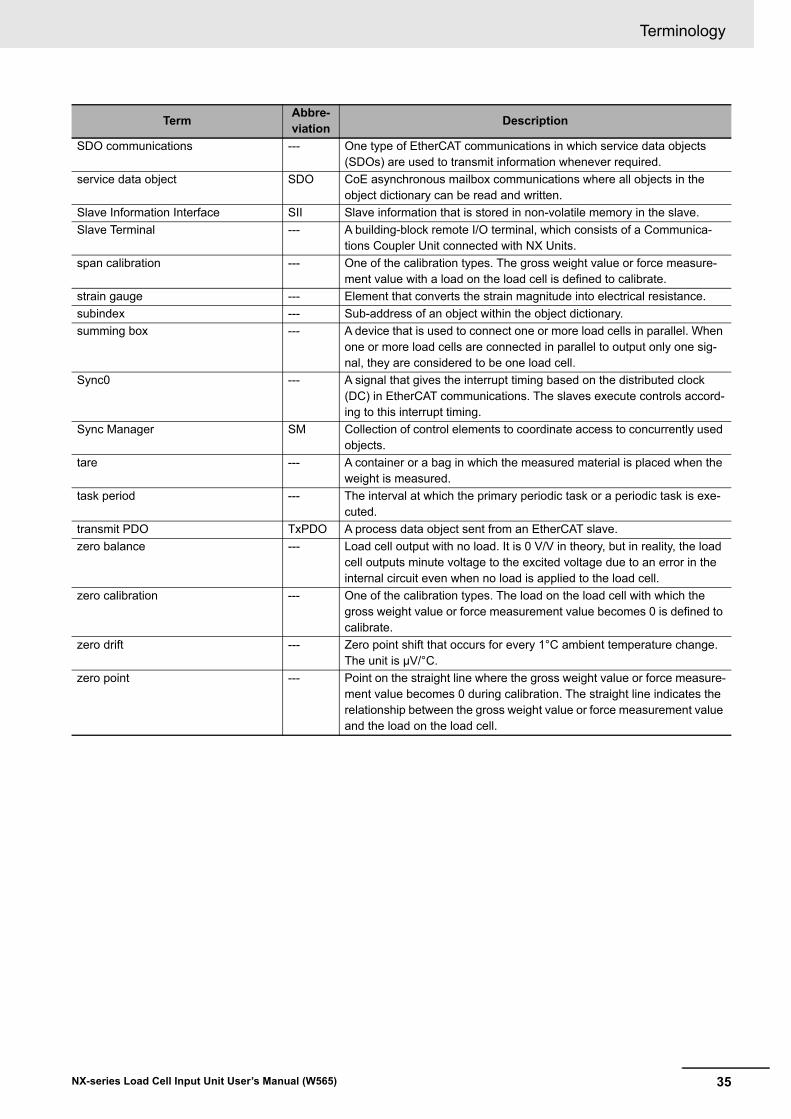
35
Terminology
NX-series Load Cell Input Unit User’s Manual (W565)
SDO communications --- One type of EtherCAT communications in which service data objects (SDOs) are used to transmit information whenever required.
service data object SDO CoE asynchronous mailbox communications where all objects in the object dictionary can be read and written.
Slave Information Interface SII Slave information that is stored in non-volatile memory in the slave.
Slave Terminal --- A building-block remote I/O terminal, which consists of a Communica-tions Coupler Unit connected with NX Units.
span calibration --- One of the calibration types. The gross weight value or force measure-ment value with a load on the load cell is defined to calibrate.
strain gauge --- Element that converts the strain magnitude into electrical resistance.
subindex --- Sub-address of an object within the object dictionary.
summing box --- A device that is used to connect one or more load cells in parallel. When one or more load cells are connected in parallel to output only one sig-nal, they are considered to be one load cell.
Sync0 --- A signal that gives the interrupt timing based on the distributed clock (DC) in EtherCAT communications. The slaves execute controls accord-ing to this interrupt timing.
Sync Manager SM Collection of control elements to coordinate access to concurrently used objects.
tare --- A container or a bag in which the measured material is placed when the weight is measured.
task period --- The interval at which the primary periodic task or a periodic task is exe-cuted.
transmit PDO TxPDO A process data object sent from an EtherCAT slave.
zero balance --- Load cell output with no load. It is 0 V/V in theory, but in reality, the load cell outputs minute voltage to the excited voltage due to an error in the internal circuit even when no load is applied to the load cell.
zero calibration --- One of the calibration types. The load on the load cell with which the gross weight value or force measurement value becomes 0 is defined to calibrate.
zero drift --- Zero point shift that occurs for every 1°C ambient temperature change. The unit is µV/°C.
zero point --- Point on the straight line where the gross weight value or force measure-ment value becomes 0 during calibration. The straight line indicates the relationship between the gross weight value or force measurement value and the load on the load cell.
TermAbbre-viation
Description
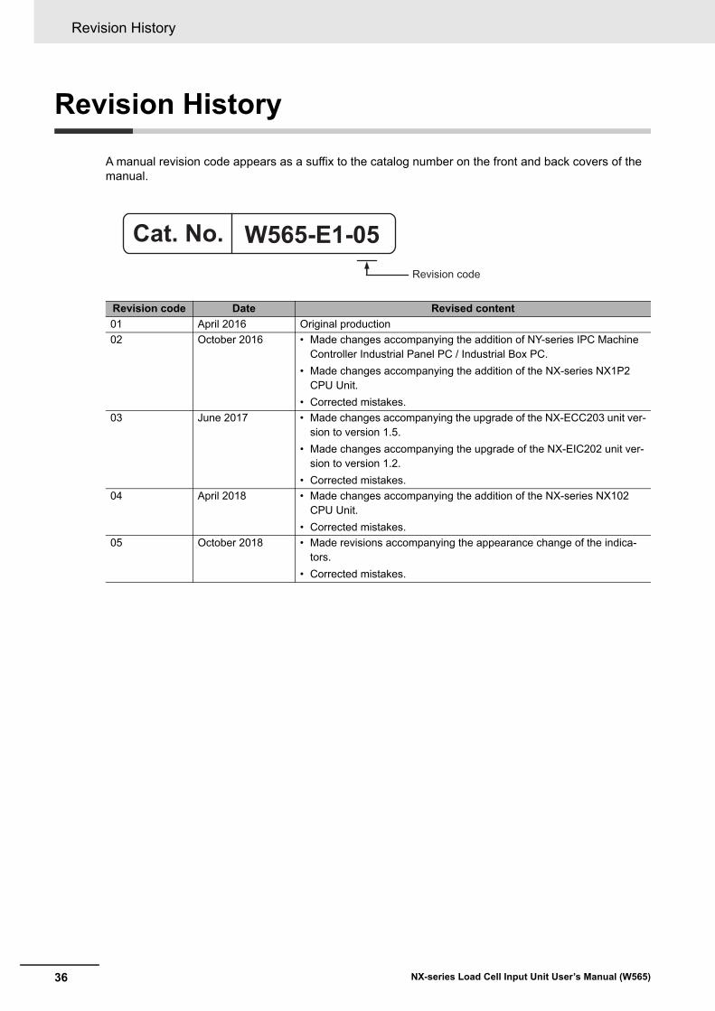
Revision History
36 NX-series Load Cell Input Unit User’s Manual (W565)
Revision History
A manual revision code appears as a suffix to the catalog number on the front and back covers of the manual.
Revision code Date Revised content
01 April 2016 Original production
02 October 2016 • Made changes accompanying the addition of NY-series IPC Machine Controller Industrial Panel PC / Industrial Box PC.
• Made changes accompanying the addition of the NX-series NX1P2 CPU Unit.
• Corrected mistakes.
03 June 2017 • Made changes accompanying the upgrade of the NX-ECC203 unit ver-sion to version 1.5.
• Made changes accompanying the upgrade of the NX-EIC202 unit ver-sion to version 1.2.
• Corrected mistakes.
04 April 2018 • Made changes accompanying the addition of the NX-series NX102 CPU Unit.
• Corrected mistakes.
05 October 2018 • Made revisions accompanying the appearance change of the indica-tors.
• Corrected mistakes.
Cat. No. W565-E1-05Revision code
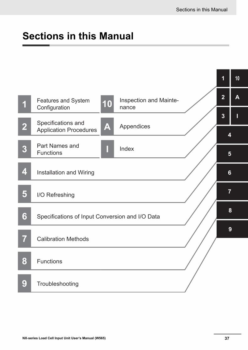
37
Sections in this Manual
NX-series Load Cell Input Unit User’s Manual (W565)
1
2
3
4
5
6
7
8
9
1 10
2 A
3 I
4
5
6
7
8
9
Features and SystemConfiguration
Specifications andApplication Procedures
Part Names andFunctions
A Appendices
I/O Refreshing
Installation and Wiring
10 Inspection and Mainte-nance
Calibration Methods
Specifications of Input Conversion and I/O Data
Functions
Troubleshooting
I Index
Sections in this Manual

Sections in this Manual
38 NX-series Load Cell Input Unit User’s Manual (W565)
1 - 1
1
NX-series Load Cell Input Unit User’s Manual (W565)
This section provides overviews of the features, system configurations, Unit models, functions of the Load Cell Input Unit, and support software.
1-1 Features of Load Cell Input Unit . . . . . . . . . . . . . . . . . . . . . . . . . . . . . . . . . . 1-2
1-2 System Configuration . . . . . . . . . . . . . . . . . . . . . . . . . . . . . . . . . . . . . . . . . . 1-41-2-1 System Configuration in the Case of a CPU Unit . . . . . . . . . . . . . . . . . . . . . . . 1-4
1-2-2 System Configuration of Slave Terminals . . . . . . . . . . . . . . . . . . . . . . . . . . . . . 1-5
1-2-3 Configuration Examples of Weight Measurement System . . . . . . . . . . . . . . . . 1-7
1-2-4 Configuration Examples of Force Measurement System . . . . . . . . . . . . . . . . . 1-9
1-3 Unit Models, Functions and Support Software . . . . . . . . . . . . . . . . . . . . . 1-101-3-1 List of Unit Models . . . . . . . . . . . . . . . . . . . . . . . . . . . . . . . . . . . . . . . . . . . . . 1-10
1-3-2 List of Functions . . . . . . . . . . . . . . . . . . . . . . . . . . . . . . . . . . . . . . . . . . . . . . . 1-10
1-3-3 Support Software . . . . . . . . . . . . . . . . . . . . . . . . . . . . . . . . . . . . . . . . . . . . . . 1-12
Features and System Configura-tion
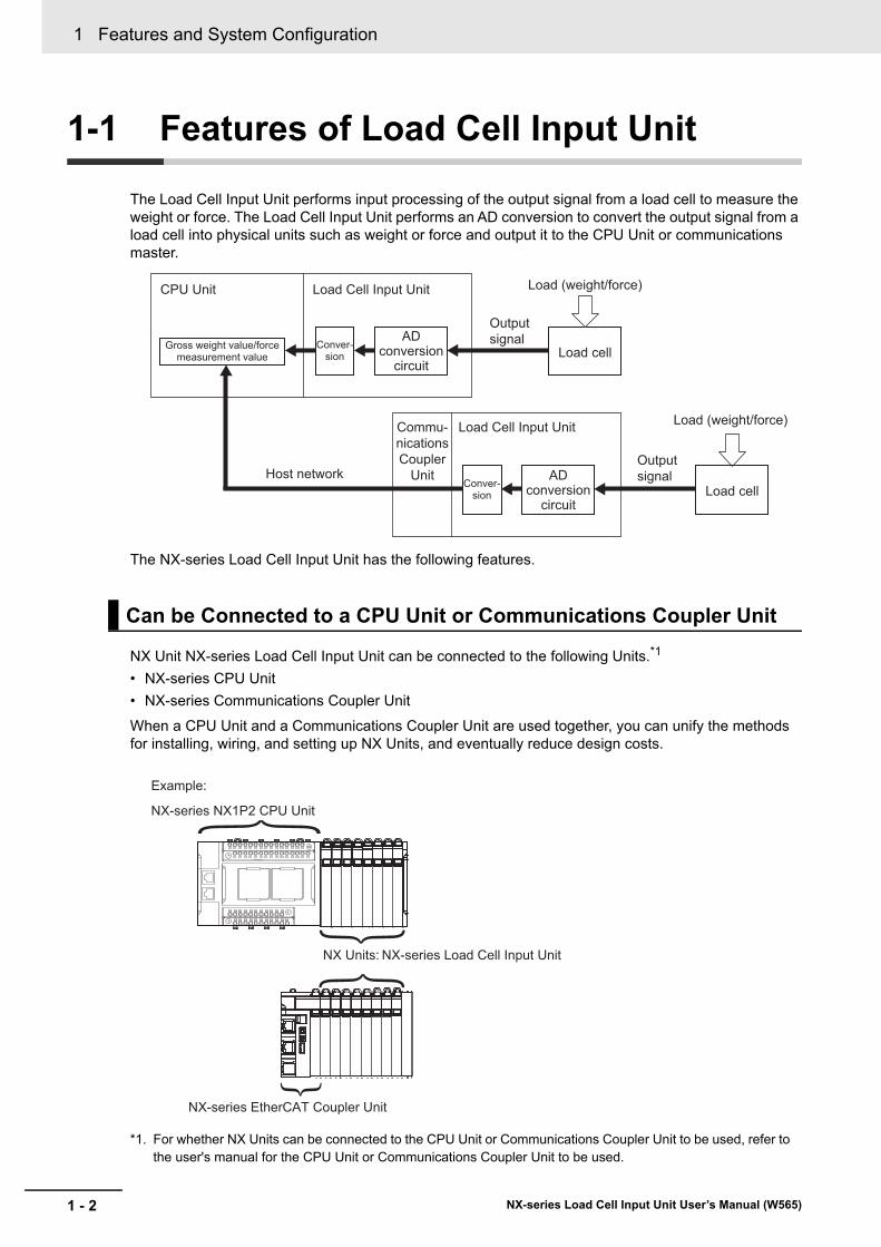
1 Features and System Configuration
1 - 2 NX-series Load Cell Input Unit User’s Manual (W565)
1-1 Features of Load Cell Input Unit
The Load Cell Input Unit performs input processing of the output signal from a load cell to measure the weight or force. The Load Cell Input Unit performs an AD conversion to convert the output signal from a load cell into physical units such as weight or force and output it to the CPU Unit or communications master.
The NX-series Load Cell Input Unit has the following features.
NX Unit NX-series Load Cell Input Unit can be connected to the following Units.*1
• NX-series CPU Unit
• NX-series Communications Coupler Unit
When a CPU Unit and a Communications Coupler Unit are used together, you can unify the methods for installing, wiring, and setting up NX Units, and eventually reduce design costs.
*1. For whether NX Units can be connected to the CPU Unit or Communications Coupler Unit to be used, refer to the user's manual for the CPU Unit or Communications Coupler Unit to be used.
Can be Connected to a CPU Unit or Communications Coupler Unit
CPU Unit
Gross weight value/force measurement value
Load Cell Input Unit
Output signal
Output signal
Load cell
Load (weight/force)
Load (weight/force)
Conver-sion
Commu-nicationsCoupler
Unit
Load Cell Input Unit
Host networkLoad cellConver-
sion
AD conversion
circuit
AD conversion
circuit
NX Units: NX-series Load Cell Input Unit
NX-series EtherCAT Coupler Unit
NX-series NX1P2 CPU Unit
Example:
1 - 3
1 Features and System Configuration
NX-series Load Cell Input Unit User’s Manual (W565)
1-1 F
eatu
res o
f Lo
ad C
ell Inp
ut
Un
it
1
When the NX-series CPU Unit or EtherCAT Coupler Unit is used together with NX Units that support synchronous I/O refreshing, the I/O control of multiple NX Units can be synchronized at the time to syn-chronize with the refresh cycle of the NX bus.
This provides an accurate I/O control because it suppresses jitter in the I/O timing of multiple NX Units.
The terminal block is a screwless clamping terminal block.
You can connect the wires simply by pushing the ferrules into the terminals. The amount of wiring work is reduced without requiring the use of screws.
The Load Cell Input Unit can measure output signals from load cells with the following accuracies.
Therefore, it is applicable to load cells with high measurement resolution.
• Nonlinearity: ±0.01% (full scale)
• Zero drift: ±0.1 μV/°C RTI
• Gain drift: ±10 ppm/°C
You can use digital filtering to suppress fluctuations of measurement values that are caused by electri-cal noise and mechanical noise, and provide stable measurements. You can freely combine the follow-ing three digital filters to use digital filtering.
• Digital low-pass filter
• Moving average filter 1
• Moving average filter 2
You can use data tracing to sample measurement values before and after digital filtering, and record the data.
You can refer to the recorded results to easily identify the noise frequency band and confirm the noise removal effect to achieve the optimum digital filter design.
You can use sensor disconnection test to check if the cable that connects the load cell and Load Cell Input Unit is disconnected.
This allows you to easily check if the connection cable is disconnected when starting up, operating, and maintaining devices.
Synchronous I/O with Refresh Cycle of the NX Bus
Simple I/O Wiring with a Screwless Clamping Terminal Block
Accuracy That is Applicable to High-precision Load Cells
Stable Measurements with Digital Filtering
Optimum Digital Filter Design
Cable Disconnection Check
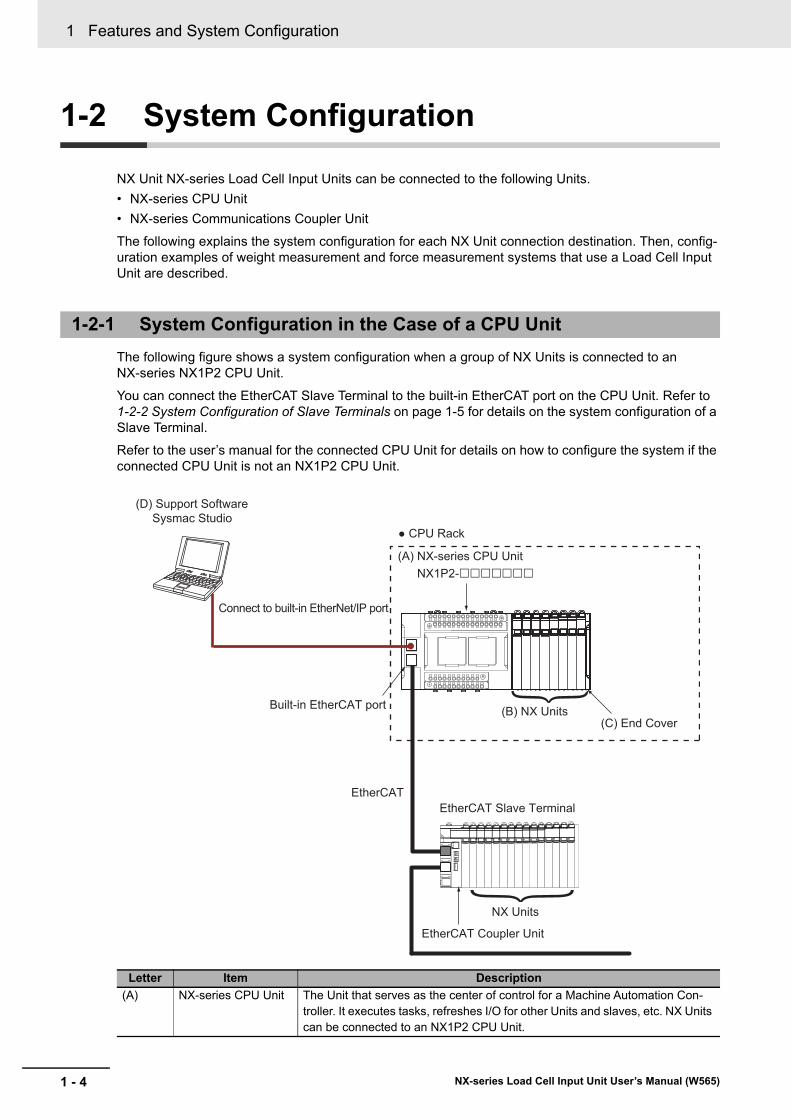
1 Features and System Configuration
1 - 4 NX-series Load Cell Input Unit User’s Manual (W565)
1-2 System Configuration
NX Unit NX-series Load Cell Input Units can be connected to the following Units.
• NX-series CPU Unit
• NX-series Communications Coupler Unit
The following explains the system configuration for each NX Unit connection destination. Then, config-uration examples of weight measurement and force measurement systems that use a Load Cell Input Unit are described.
The following figure shows a system configuration when a group of NX Units is connected to an NX-series NX1P2 CPU Unit.
You can connect the EtherCAT Slave Terminal to the built-in EtherCAT port on the CPU Unit. Refer to 1-2-2 System Configuration of Slave Terminals on page 1-5 for details on the system configuration of a Slave Terminal.
Refer to the user’s manual for the connected CPU Unit for details on how to configure the system if the connected CPU Unit is not an NX1P2 CPU Unit.
1-2-1 System Configuration in the Case of a CPU Unit
Letter Item Description
(A) NX-series CPU Unit The Unit that serves as the center of control for a Machine Automation Con-troller. It executes tasks, refreshes I/O for other Units and slaves, etc. NX Units can be connected to an NX1P2 CPU Unit.
(A) NX-series CPU Unit
EtherCAT Slave Terminal
(D) Support Software Sysmac Studio
Built-in EtherCAT port
Connect to built-in EtherNet/IP port
(B) NX Units
CPU Rack
NX1P2-
(C) End Cover
EtherCAT
NX Units
EtherCAT Coupler Unit
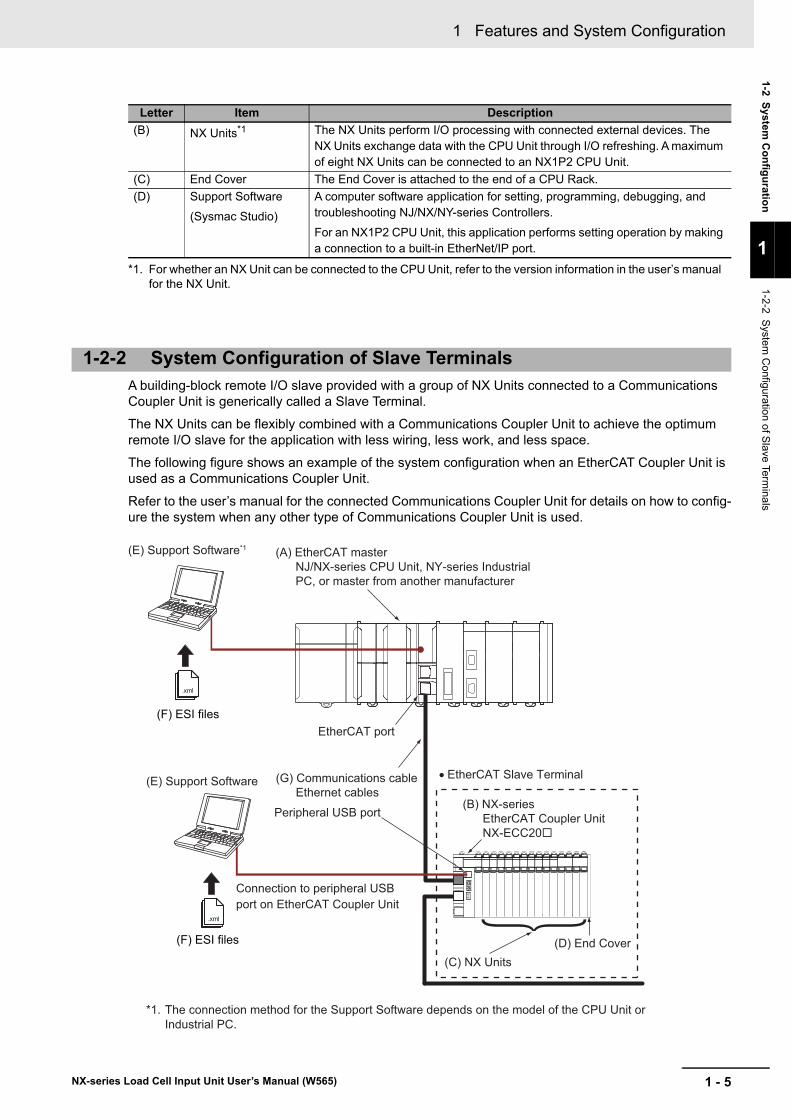
1 - 5
1 Features and System Configuration
NX-series Load Cell Input Unit User’s Manual (W565)
1-2 System
Co
nfig
uratio
n
1
1-2-2 S
ystem C
onfiguration of S
lave Termina
ls
A building-block remote I/O slave provided with a group of NX Units connected to a Communications Coupler Unit is generically called a Slave Terminal.
The NX Units can be flexibly combined with a Communications Coupler Unit to achieve the optimum remote I/O slave for the application with less wiring, less work, and less space.
The following figure shows an example of the system configuration when an EtherCAT Coupler Unit is used as a Communications Coupler Unit.
Refer to the user’s manual for the connected Communications Coupler Unit for details on how to config-ure the system when any other type of Communications Coupler Unit is used.
(B) NX Units*1 The NX Units perform I/O processing with connected external devices. The NX Units exchange data with the CPU Unit through I/O refreshing. A maximum of eight NX Units can be connected to an NX1P2 CPU Unit.
(C) End Cover The End Cover is attached to the end of a CPU Rack.
(D) Support Software
(Sysmac Studio)
A computer software application for setting, programming, debugging, and troubleshooting NJ/NX/NY-series Controllers.
For an NX1P2 CPU Unit, this application performs setting operation by making a connection to a built-in EtherNet/IP port.
*1. For whether an NX Unit can be connected to the CPU Unit, refer to the version information in the user’s manual for the NX Unit.
1-2-2 System Configuration of Slave Terminals
Letter Item Description
.xml
.xml
(E) Support Software*1 (A) EtherCAT masterNJ/NX-series CPU Unit, NY-series Industrial PC, or master from another manufacturer
(F) ESI filesEtherCAT port
(E) Support Software (G) Communications cableEthernet cables
Peripheral USB port
• EtherCAT Slave Terminal
(B) NX-seriesEtherCAT Coupler UnitNX-ECC20
(D) End Cover(C) NX Units
Connection to peripheral USB port on EtherCAT Coupler Unit
(F) ESI files
*1. The connection method for the Support Software depends on the model of the CPU Unit or Industrial PC.
1 Features and System Configuration
1 - 6 NX-series Load Cell Input Unit User’s Manual (W565)
Letter Item Description
(A) EtherCAT master *1
*1. An EtherCAT Slave Terminal cannot be connected to any of the OMRON CJ1W-NC81/82 Position Control Units even though they can operate as EtherCAT masters.
The EtherCAT master manages the network, monitors the status of slaves, and exchanges I/O data with slaves.
(B) EtherCAT Coupler Unit The EtherCAT Coupler Unit serves as an interface for process data com-munications on the EtherCAT network between the NX Units and the Eth-erCAT master.
The I/O data for the NX Units is accumulated in the EtherCAT Coupler Unit and then all of the data is exchanged with the EtherCAT master at the same time.
The EtherCAT Coupler Unit can also perform message communications (SDO communications) with the EtherCAT master.
(C) NX Units*2
*2. For whether an NX Unit can be connected to the Communications Coupler Unit, refer to the version information in the user’s manual for the NX Unit.
The NX Units perform I/O processing with connected external devices.
The NX Units perform process data communications with the EtherCAT master through the EtherCAT Coupler Unit. The Load Cell Input Unit is one of the NX Units.
(D) End Cover The End Cover is attached to the end of the Slave Terminal.
(E) Support Software *3 *4
*3. The term Support Software indicates software that is provided by OMRON. If you connect to a master from another company, use the software tool corresponding to that master.
*4. Refer to 1-3-3 Support Software on page 1-12 for information on Support Software.
The Sysmac Studio runs on a personal computer and it is used to config-ure the EtherCAT network and EtherCAT Slave Terminal, and to program, monitor, and troubleshoot the Controllers.
(F) ESI (EtherCAT Slave Information) file
The ESI file contains information that is unique to the EtherCAT Slave Ter-minal in XML format. You can load the ESI file into the Support Software to easily allocate Slave Terminal process data and configure other settings.
The ESI files for OMRON EtherCAT slaves are already installed in the Support Software. You can update the Support Software to get the ESI files for the most recent models.
(G) Communications cable Use a double-shielded cable with aluminum tape and braiding of Ethernet category 5 (100Base-TX) or higher, and use straight wiring.
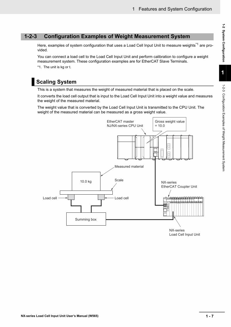
1 - 7
1 Features and System Configuration
NX-series Load Cell Input Unit User’s Manual (W565)
1-2 System
Co
nfig
uratio
n
1
1-2-3 C
onfiguration Exam
ples of W
eight M
easurement S
ystem
Here, examples of system configuration that uses a Load Cell Input Unit to measure weights*1 are pro-vided.
You can connect a load cell to the Load Cell Input Unit and perform calibration to configure a weight measurement system. These configuration examples are for EtherCAT Slave Terminals.
*1. The unit is kg or t.
This is a system that measures the weight of measured material that is placed on the scale.
It converts the load cell output that is input to the Load Cell Input Unit into a weight value and measures the weight of the measured material.
The weight value that is converted by the Load Cell Input Unit is transmitted to the CPU Unit. The weight of the measured material can be measured as a gross weight value.
1-2-3 Configuration Examples of Weight Measurement System
Scaling System
EtherCAT master NJ/NX-series CPU Unit
NX-series EtherCAT Coupler Unit
NX-series Load Cell Input Unit
Summing box
10.0 kg
Load cell Load cell
Scale
Measured material
Gross weight value = 10.0
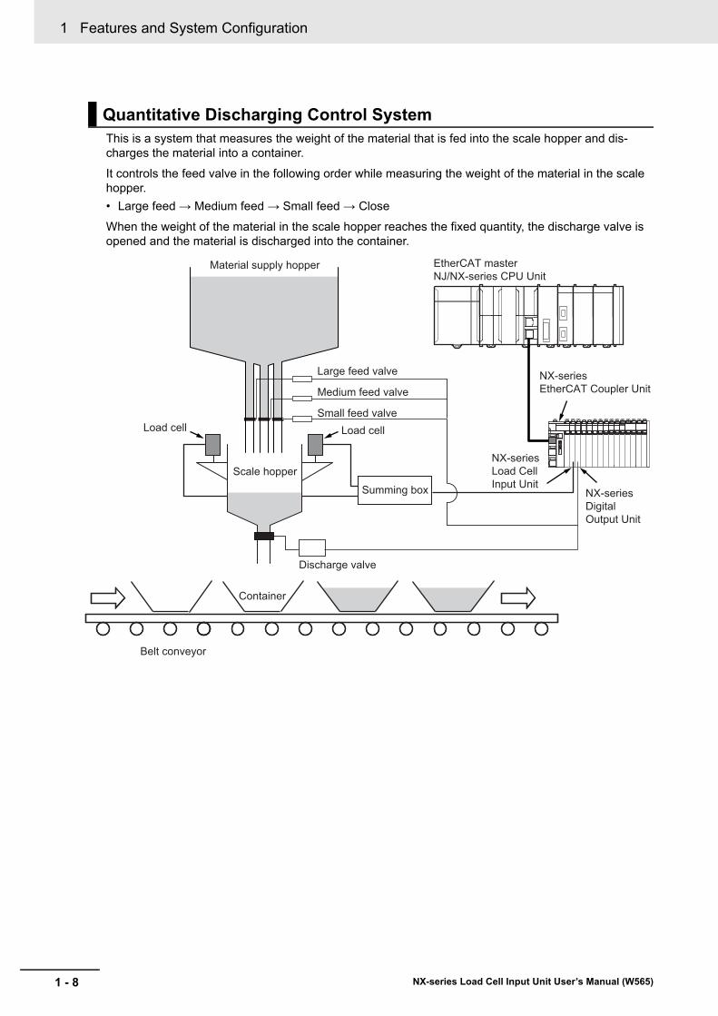
1 Features and System Configuration
1 - 8 NX-series Load Cell Input Unit User’s Manual (W565)
This is a system that measures the weight of the material that is fed into the scale hopper and dis-charges the material into a container.
It controls the feed valve in the following order while measuring the weight of the material in the scale hopper.
• Large feed → Medium feed → Small feed → Close
When the weight of the material in the scale hopper reaches the fixed quantity, the discharge valve is opened and the material is discharged into the container.
Quantitative Discharging Control System
Material supply hopper
Summing boxScale hopper
Container
Belt conveyor
Load cell Load cell
Large feed valve
Medium feed valve
Small feed valve
Discharge valve
NX-series Load Cell Input Unit
EtherCAT master NJ/NX-series CPU Unit
NX-series EtherCAT Coupler Unit
NX-series Digital Output Unit
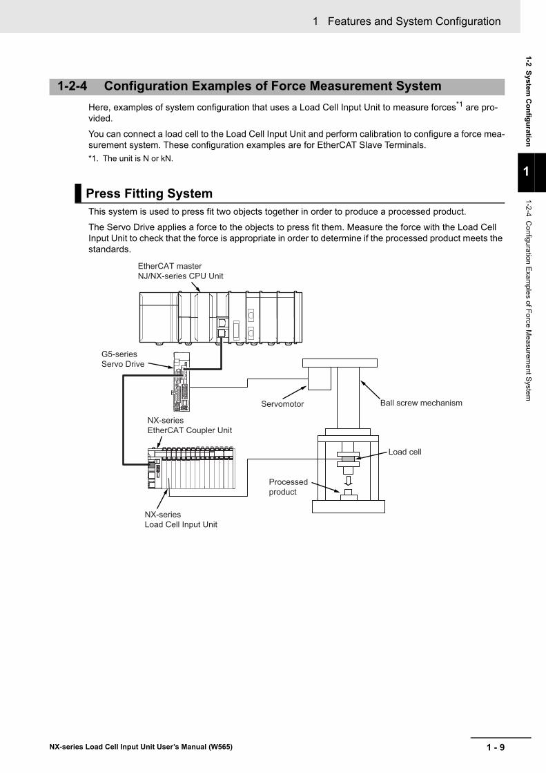
1 - 9
1 Features and System Configuration
NX-series Load Cell Input Unit User’s Manual (W565)
1-2 System
Co
nfig
uratio
n
1
1-2-4 C
onfiguration Exam
ples of F
orce Measurem
ent S
ystem
Here, examples of system configuration that uses a Load Cell Input Unit to measure forces*1 are pro-vided.
You can connect a load cell to the Load Cell Input Unit and perform calibration to configure a force mea-surement system. These configuration examples are for EtherCAT Slave Terminals.
*1. The unit is N or kN.
This system is used to press fit two objects together in order to produce a processed product.
The Servo Drive applies a force to the objects to press fit them. Measure the force with the Load Cell Input Unit to check that the force is appropriate in order to determine if the processed product meets the standards.
1-2-4 Configuration Examples of Force Measurement System
Press Fitting System
EtherCAT master NJ/NX-series CPU Unit
G5-series Servo Drive
NX-series EtherCAT Coupler Unit
NX-series Load Cell Input Unit
Ball screw mechanism
Processed product
Load cell
Servomotor
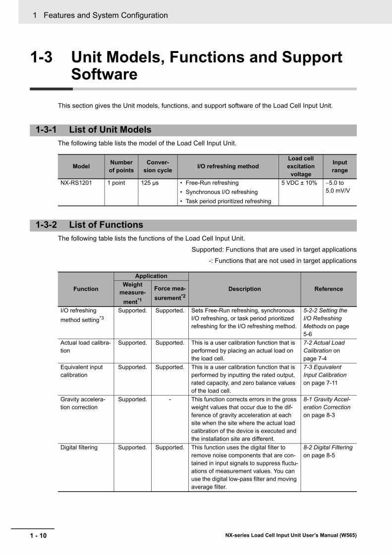
1 Features and System Configuration
1 - 10 NX-series Load Cell Input Unit User’s Manual (W565)
1-3 Unit Models, Functions and Support Software
This section gives the Unit models, functions, and support software of the Load Cell Input Unit.
The following table lists the model of the Load Cell Input Unit.
The following table lists the functions of the Load Cell Input Unit.
Supported: Functions that are used in target applications
-: Functions that are not used in target applications
1-3-1 List of Unit Models
ModelNumber of points
Conver-sion cycle
I/O refreshing methodLoad cell excitation
voltage
Input range
NX-RS1201 1 point 125 µs • Free-Run refreshing
• Synchronous I/O refreshing
• Task period prioritized refreshing
5 VDC ± 10% 5.0 to 5.0 mV/V
1-3-2 List of Functions
Function
Application
Description ReferenceWeight
measure-
ment*1
Force mea-
surement*2
I/O refreshing
method setting*3
Supported. Supported. Sets Free-Run refreshing, synchronous I/O refreshing, or task period prioritized refreshing for the I/O refreshing method.
5-2-2 Setting the I/O Refreshing Methods on page 5-6
Actual load calibra-tion
Supported. Supported. This is a user calibration function that is performed by placing an actual load on the load cell.
7-2 Actual Load Calibration on page 7-4
Equivalent input calibration
Supported. Supported. This is a user calibration function that is performed by inputting the rated output, rated capacity, and zero balance values of the load cell.
7-3 Equivalent Input Calibration on page 7-11
Gravity accelera-tion correction
Supported. - This function corrects errors in the gross weight values that occur due to the dif-ference of gravity acceleration at each site when the site where the actual load calibration of the device is executed and the installation site are different.
8-1 Gravity Accel-eration Correction on page 8-3
Digital filtering Supported. Supported. This function uses the digital filter to remove noise components that are con-tained in input signals to suppress fluctu-ations of measurement values. You can use the digital low-pass filter and moving average filter.
8-2 Digital Filtering on page 8-5
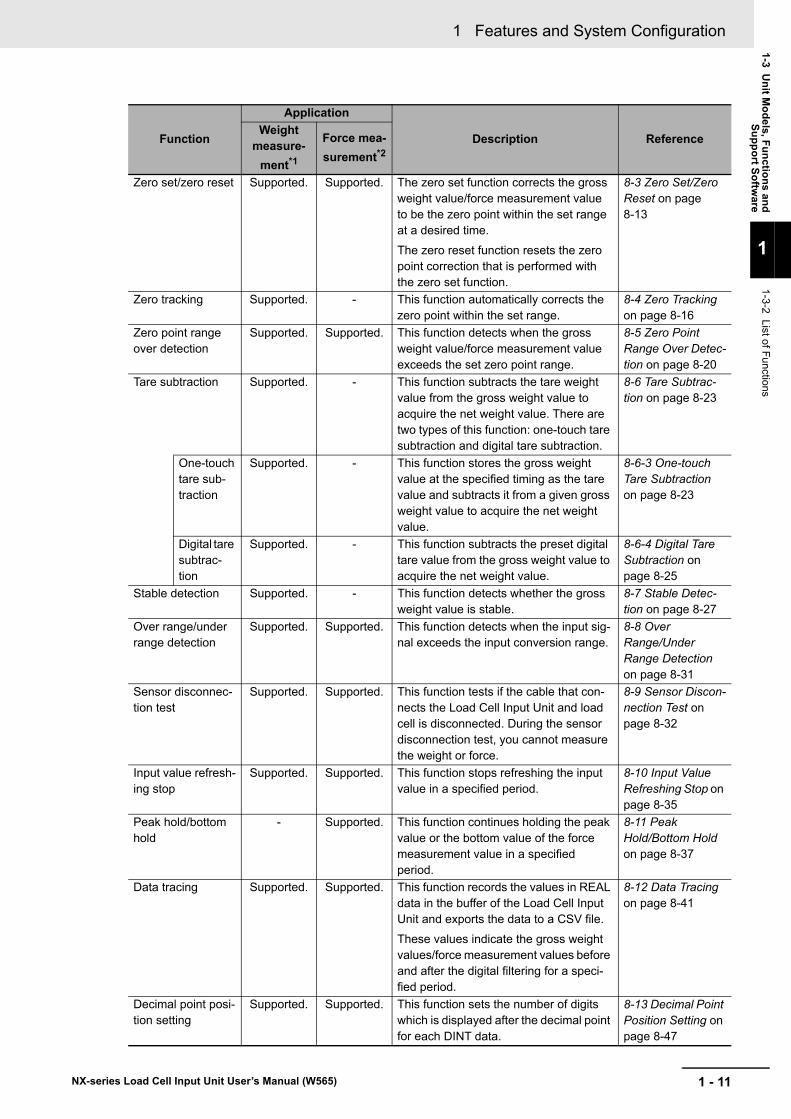
1 - 11
1 Features and System Configuration
NX-series Load Cell Input Unit User’s Manual (W565)
1-3 Un
it Mo
dels, F
un
ction
s and
Su
pp
ort S
oftw
are
1
1-3-2 List of F
unctions
Zero set/zero reset Supported. Supported. The zero set function corrects the gross weight value/force measurement value to be the zero point within the set range at a desired time.
The zero reset function resets the zero point correction that is performed with the zero set function.
8-3 Zero Set/Zero Reset on page 8-13
Zero tracking Supported. - This function automatically corrects the zero point within the set range.
8-4 Zero Tracking on page 8-16
Zero point range over detection
Supported. Supported. This function detects when the gross weight value/force measurement value exceeds the set zero point range.
8-5 Zero Point Range Over Detec-tion on page 8-20
Tare subtraction Supported. - This function subtracts the tare weight value from the gross weight value to acquire the net weight value. There are two types of this function: one-touch tare subtraction and digital tare subtraction.
8-6 Tare Subtrac-tion on page 8-23
One-touch tare sub-traction
Supported. - This function stores the gross weight value at the specified timing as the tare value and subtracts it from a given gross weight value to acquire the net weight value.
8-6-3 One-touch Tare Subtraction on page 8-23
Digital tare subtrac-tion
Supported. - This function subtracts the preset digital tare value from the gross weight value to acquire the net weight value.
8-6-4 Digital Tare Subtraction on page 8-25
Stable detection Supported. - This function detects whether the gross weight value is stable.
8-7 Stable Detec-tion on page 8-27
Over range/under range detection
Supported. Supported. This function detects when the input sig-nal exceeds the input conversion range.
8-8 Over Range/Under Range Detection on page 8-31
Sensor disconnec-tion test
Supported. Supported. This function tests if the cable that con-nects the Load Cell Input Unit and load cell is disconnected. During the sensor disconnection test, you cannot measure the weight or force.
8-9 Sensor Discon-nection Test on page 8-32
Input value refresh-ing stop
Supported. Supported. This function stops refreshing the input value in a specified period.
8-10 Input Value Refreshing Stop on page 8-35
Peak hold/bottom hold
- Supported. This function continues holding the peak value or the bottom value of the force measurement value in a specified period.
8-11 Peak Hold/Bottom Hold on page 8-37
Data tracing Supported. Supported. This function records the values in REAL data in the buffer of the Load Cell Input Unit and exports the data to a CSV file.
These values indicate the gross weight values/force measurement values before and after the digital filtering for a speci-fied period.
8-12 Data Tracing on page 8-41
Decimal point posi-tion setting
Supported. Supported. This function sets the number of digits which is displayed after the decimal point for each DINT data.
8-13 Decimal Point Position Setting on page 8-47
Function
Application
Description ReferenceWeight
measure-
ment*1
Force mea-
surement*2
1 Features and System Configuration
1 - 12 NX-series Load Cell Input Unit User’s Manual (W565)
The Support Software that is used depends on the system configuration.
Support Software for a System Configured with a CPU Unit
If your system is configured by connecting an NX Unit to a CPU Unit, the Sysmac Studio is used as the Support Software.
Support Software for a System Configured with a Slave Terminal
If your system is configured by connecting an NX Unit to a Communications Coupler Unit, refer to the user’s manual for the Communications Coupler Unit for information on the Support Software.
Refer to A-4 Version Information with CPU Units on page A-18 or A-5 Version Information with Communications Coupler Units on page A-19 for information on the Support Software versions.
*1. It is used to measure the weight in the unit of kg or t.
*2. It is used to measure the force in the unit of N or kN.
*3. Refer to 5-2-2 Setting the I/O Refreshing Methods on page 5-6 for details on the setting method.
1-3-3 Support Software
2 - 1
2
NX-series Load Cell Input Unit User’s Manual (W565)
This section provides the specifications of the Load Cell Input Unit and describes how to use the Load Cell Input Unit.
2-1 Specifications . . . . . . . . . . . . . . . . . . . . . . . . . . . . . . . . . . . . . . . . . . . . . . . . . 2-22-1-1 General Specifications . . . . . . . . . . . . . . . . . . . . . . . . . . . . . . . . . . . . . . . . . . . 2-2
2-1-2 Individual Specifications . . . . . . . . . . . . . . . . . . . . . . . . . . . . . . . . . . . . . . . . . . 2-3
2-2 Operating Procedures . . . . . . . . . . . . . . . . . . . . . . . . . . . . . . . . . . . . . . . . . . 2-7
Specifications and Application Procedures
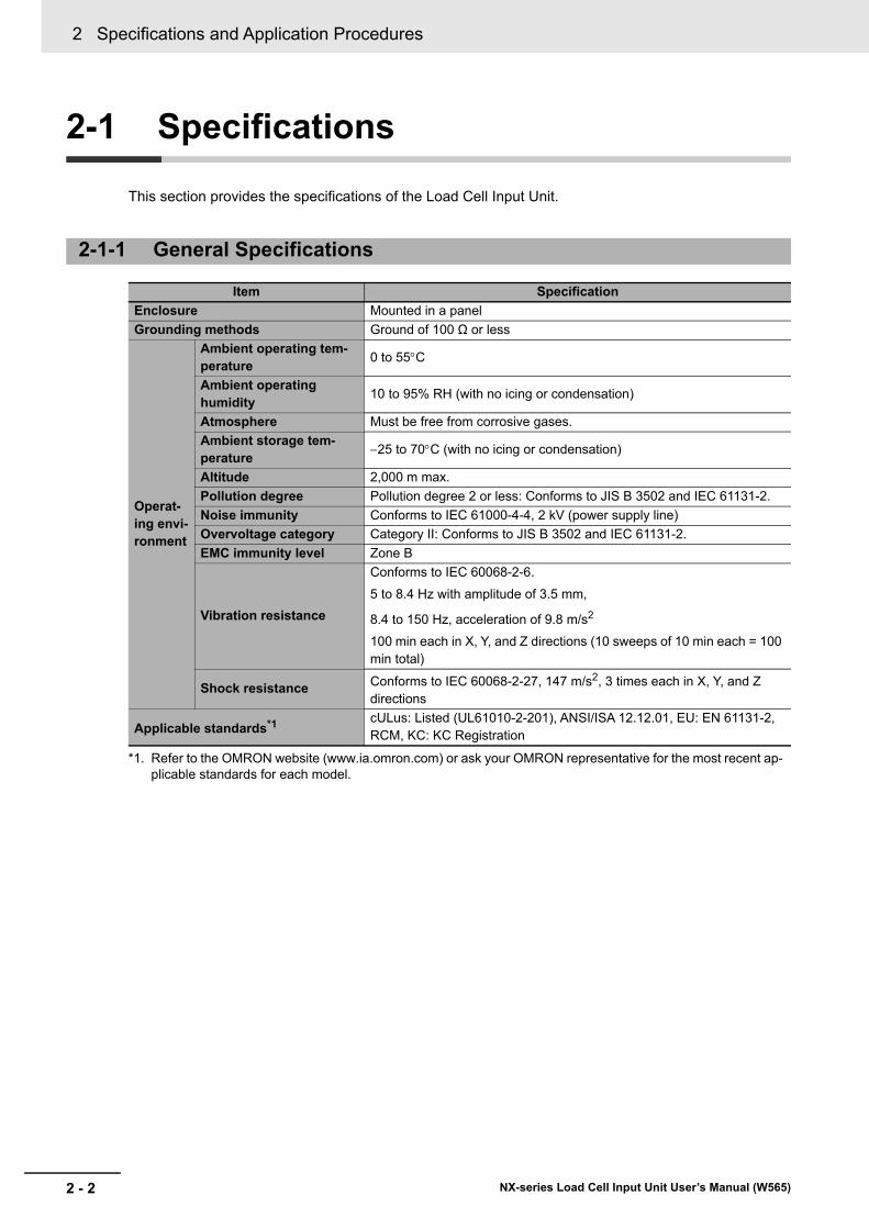
2 Specifications and Application Procedures
2 - 2 NX-series Load Cell Input Unit User’s Manual (W565)
2-1 Specifications
This section provides the specifications of the Load Cell Input Unit.
2-1-1 General Specifications
Item Specification
Enclosure Mounted in a panel
Grounding methods Ground of 100 Ω or less
Operat-ing envi-ronment
Ambient operating tem-perature
0 to 55C
Ambient operating humidity
10 to 95% RH (with no icing or condensation)
Atmosphere Must be free from corrosive gases.
Ambient storage tem-perature
25 to 70C (with no icing or condensation)
Altitude 2,000 m max.
Pollution degree Pollution degree 2 or less: Conforms to JIS B 3502 and IEC 61131-2.
Noise immunity Conforms to IEC 61000-4-4, 2 kV (power supply line)
Overvoltage category Category II: Conforms to JIS B 3502 and IEC 61131-2.
EMC immunity level Zone B
Vibration resistance
Conforms to IEC 60068-2-6.
5 to 8.4 Hz with amplitude of 3.5 mm,
8.4 to 150 Hz, acceleration of 9.8 m/s2
100 min each in X, Y, and Z directions (10 sweeps of 10 min each = 100 min total)
Shock resistance Conforms to IEC 60068-2-27, 147 m/s2, 3 times each in X, Y, and Z directions
Applicable standards*1
*1. Refer to the OMRON website (www.ia.omron.com) or ask your OMRON representative for the most recent ap-plicable standards for each model.
cULus: Listed (UL61010-2-201), ANSI/ISA 12.12.01, EU: EN 61131-2, RCM, KC: KC Registration
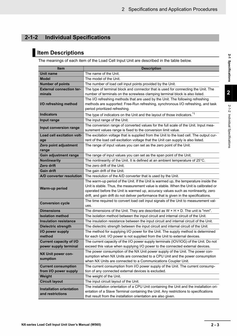
2 - 3
2 Specifications and Application Procedures
NX-series Load Cell Input Unit User’s Manual (W565)
2-1 Sp
ecificatio
ns
2
2-1-2 Individual Spe
cifications
The meanings of each item of the Load Cell Input Unit are described in the table below.
2-1-2 Individual Specifications
Item Descriptions
Item Description
Unit name The name of the Unit.
Model The model of the Unit.
Number of points The number of load cell input points provided by the Unit.
External connection ter-minals
The type of terminal block and connector that is used for connecting the Unit. The number of terminals on the screwless clamping terminal block is also listed.
I/O refreshing methodThe I/O refreshing methods that are used by the Unit. The following refreshing methods are supported: Free-Run refreshing, synchronous I/O refreshing, and task period prioritized refreshing.
Indicators The type of indicators on the Unit and the layout of those indicators.*1
Input range The input range of the Unit.
Input conversion rangeThe conversion range of converted values for the full scale of the Unit. Input mea-surement values range is fixed to the conversion limit value.
Load cell excitation volt-age
The excitation voltage that is supplied from the Unit to the load cell. The output cur-rent of the load cell excitation voltage that the Unit can supply is also listed.
Zero point adjustment range
The range of input values you can set as the zero point of the Unit.
Gain adjustment range The range of input values you can set as the span point of the Unit.
Nonlinearity The nonlinearity of the Unit. It is defined at an ambient temperature of 25°C.
Zero drift The zero drift of the Unit.
Gain drift The gain drift of the Unit.
A/D converter resolution The resolution of the A/D converter that is used by the Unit.
Warm-up period
The warm-up period of the Unit. If the Unit is warmed up, the temperature inside the Unit is stable. Thus, the measurement value is stable. When the Unit is calibrated or operated before the Unit is warmed up, accuracy values such as nonlinearity, zero drift, and gain drift do not deliver performance that is given in the specifications.
Conversion cycleThe time required to convert load cell input signals of the Unit to measurement val-ues.
Dimensions The dimensions of the Unit. They are described as W × H × D. The unit is "mm".
Isolation method The isolation method between the input circuit and internal circuit of the Unit.
Insulation resistance The insulation resistance between the input circuit and internal circuit of the Unit.
Dielectric strength The dielectric strength between the input circuit and internal circuit of the Unit.
I/O power supply method
The method for supplying I/O power for the Unit. The supply method is determined for each Unit. I/O power is not supplied from the Unit to external devices.
Current capacity of I/O power supply terminal
The current capacity of the I/O power supply terminals (IOV/IOG) of the Unit. Do not exceed this value when supplying I/O power to the connected external devices.
NX Unit power con-sumption
The power consumption of the NX Unit power supply of the Unit. The power con-sumption when NX Units are connected to a CPU Unit and the power consumption when NX Units are connected to a Communications Coupler Unit.
Current consumption from I/O power supply
The current consumption from I/O power supply of the Unit. The current consump-tion of any connected external devices is excluded.
Weight The weight of the Unit.
Circuit layout The input circuit layout of the Unit.
Installation orientation and restrictions
The installation orientation of a CPU Unit containing the Unit and the installation ori-entation of a Slave Terminal containing the Unit. Any restrictions to specifications that result from the installation orientation are also given.
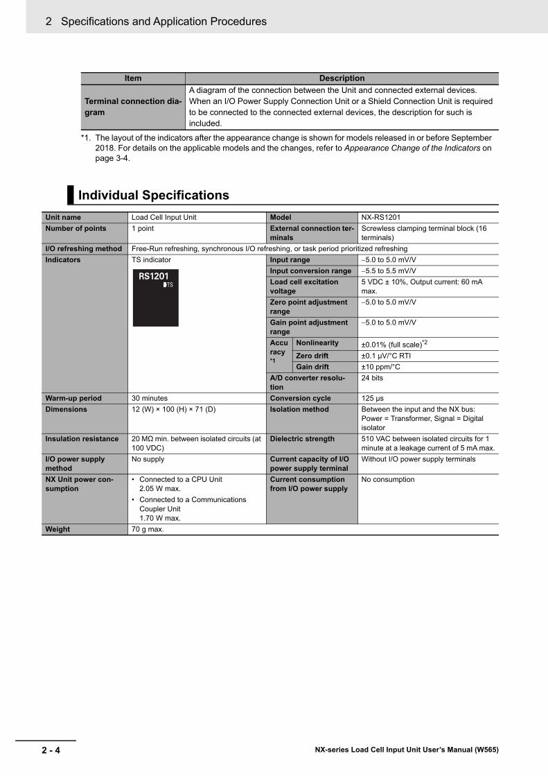
2 Specifications and Application Procedures
2 - 4 NX-series Load Cell Input Unit User’s Manual (W565)
Terminal connection dia-gram
A diagram of the connection between the Unit and connected external devices. When an I/O Power Supply Connection Unit or a Shield Connection Unit is required to be connected to the connected external devices, the description for such is included.
*1. The layout of the indicators after the appearance change is shown for models released in or before September 2018. For details on the applicable models and the changes, refer to Appearance Change of the Indicators on page 3-4.
Individual Specifications
Unit name Load Cell Input Unit Model NX-RS1201
Number of points 1 point External connection ter-minals
Screwless clamping terminal block (16 terminals)
I/O refreshing method Free-Run refreshing, synchronous I/O refreshing, or task period prioritized refreshing
Indicators TS indicator Input range 5.0 to 5.0 mV/V
Input conversion range 5.5 to 5.5 mV/V
Load cell excitation voltage
5 VDC ± 10%, Output current: 60 mA max.
Zero point adjustment range
5.0 to 5.0 mV/V
Gain point adjustment range
5.0 to 5.0 mV/V
Accuracy*1
Nonlinearity ±0.01% (full scale)*2
Zero drift ±0.1 μV/°C RTI
Gain drift ±10 ppm/°C
A/D converter resolu-tion
24 bits
Warm-up period 30 minutes Conversion cycle 125 µs
Dimensions 12 (W) × 100 (H) × 71 (D) Isolation method Between the input and the NX bus: Power = Transformer, Signal = Digital isolator
Insulation resistance 20 MΩ min. between isolated circuits (at 100 VDC)
Dielectric strength 510 VAC between isolated circuits for 1 minute at a leakage current of 5 mA max.
I/O power supply method
No supply Current capacity of I/O power supply terminal
Without I/O power supply terminals
NX Unit power con-sumption
• Connected to a CPU Unit 2.05 W max.
• Connected to a Communications Coupler Unit 1.70 W max.
Current consumption from I/O power supply
No consumption
Weight 70 g max.
Item Description
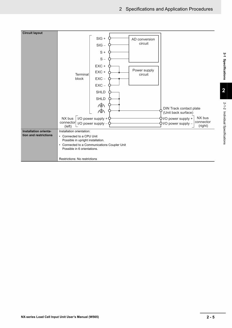
2 - 5
2 Specifications and Application Procedures
NX-series Load Cell Input Unit User’s Manual (W565)
2-1 Sp
ecificatio
ns
2
2-1-2 Individual Spe
cifications
Circuit layout
Installation orienta-tion and restrictions
Installation orientation:
• Connected to a CPU Unit Possible in upright installation.
• Connected to a Communications Coupler Unit Possible in 6 orientations.
Restrictions: No restrictions
SHLD
DIN Track contact plate (Unit back surface)
Terminal block
SIG −
SIG +
S −
S +
Power supply circuit
EXC +EXC +
I/O power supply +I/O power supply −
I/O power supply +I/O power supply −
NX bus connector
(left)
NX bus connector
(right)
EXC −
EXC −
SHLD
AD conversion circuit
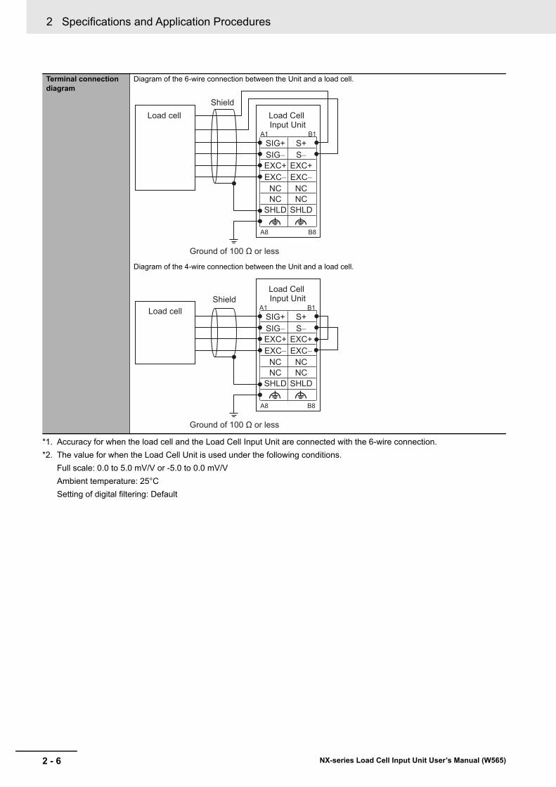
2 Specifications and Application Procedures
2 - 6 NX-series Load Cell Input Unit User’s Manual (W565)
Terminal connection diagram
Diagram of the 6-wire connection between the Unit and a load cell.
Diagram of the 4-wire connection between the Unit and a load cell.
*1. Accuracy for when the load cell and the Load Cell Input Unit are connected with the 6-wire connection.
*2. The value for when the Load Cell Unit is used under the following conditions.
Full scale: 0.0 to 5.0 mV/V or -5.0 to 0.0 mV/V
Ambient temperature: 25°C
Setting of digital filtering: Default
SHLDNC
SHLD
EXC− EXC−
SIG− S−EXC+ EXC+
SIG+ S+
NCNC NC
Load Cell Input Unit
Load cellShield
Ground of 100 Ω or less
A1 B1
A8 B8
SHLDNC
SHLD
EXC− EXC−
SIG− S−EXC+ EXC+
SIG+ S+
NCNC NC
Load Cell Input Unit
Load cell
Ground of 100 Ω or less
A1 B1
A8 B8
Shield
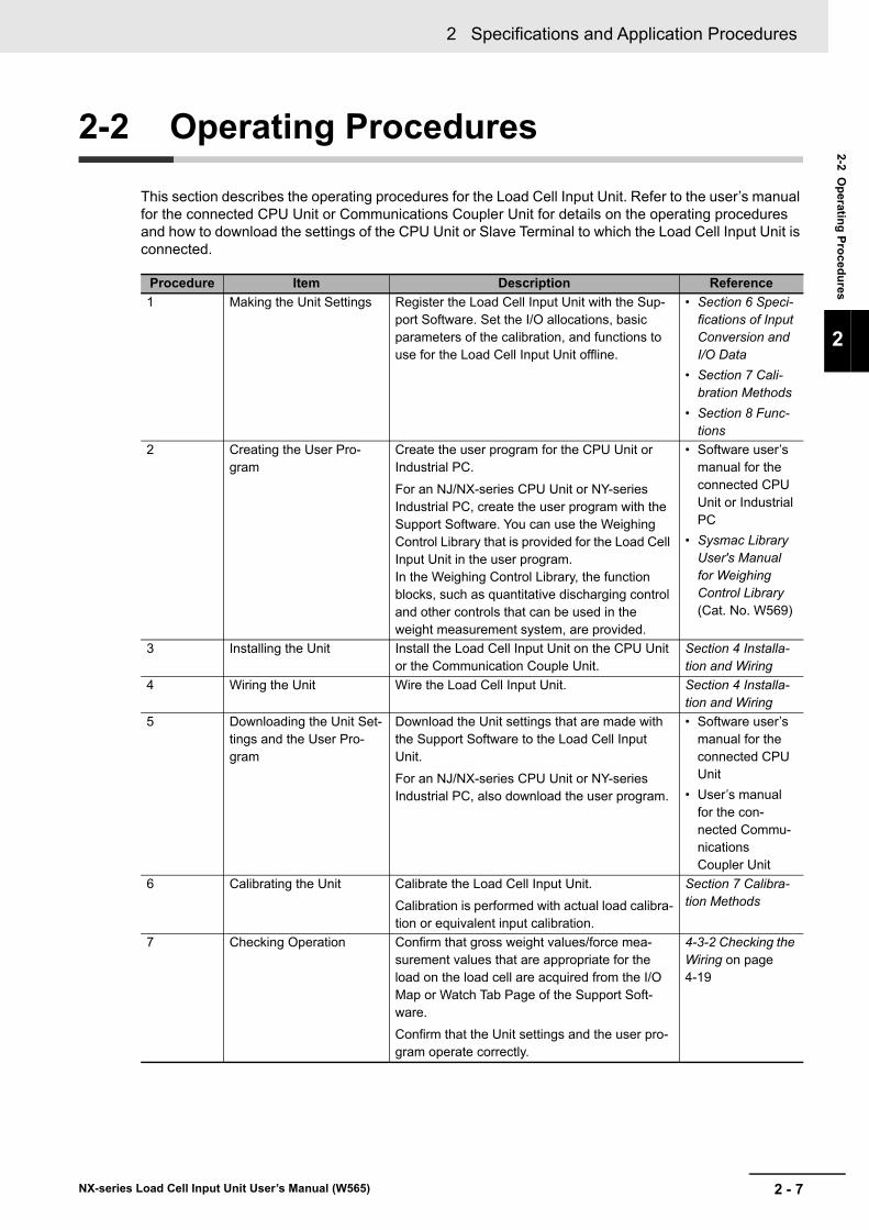
2 - 7
2 Specifications and Application Procedures
NX-series Load Cell Input Unit User’s Manual (W565)
2-2 Op
erating
Pro
cedu
res
2
2-2 Operating Procedures
This section describes the operating procedures for the Load Cell Input Unit. Refer to the user’s manual for the connected CPU Unit or Communications Coupler Unit for details on the operating procedures and how to download the settings of the CPU Unit or Slave Terminal to which the Load Cell Input Unit is connected.
Procedure Item Description Reference
1 Making the Unit Settings Register the Load Cell Input Unit with the Sup-port Software. Set the I/O allocations, basic parameters of the calibration, and functions to use for the Load Cell Input Unit offline.
• Section 6 Speci-fications of Input Conversion and I/O Data
• Section 7 Cali-bration Methods
• Section 8 Func-tions
2 Creating the User Pro-gram
Create the user program for the CPU Unit or Industrial PC.
For an NJ/NX-series CPU Unit or NY-series Industrial PC, create the user program with the Support Software. You can use the Weighing Control Library that is provided for the Load Cell Input Unit in the user program. In the Weighing Control Library, the function blocks, such as quantitative discharging control and other controls that can be used in the weight measurement system, are provided.
• Software user’s manual for the connected CPU Unit or Industrial PC
• Sysmac Library User's Manual for Weighing Control Library (Cat. No. W569)
3 Installing the Unit Install the Load Cell Input Unit on the CPU Unit or the Communication Couple Unit.
Section 4 Installa-tion and Wiring
4 Wiring the Unit Wire the Load Cell Input Unit. Section 4 Installa-tion and Wiring
5 Downloading the Unit Set-tings and the User Pro-gram
Download the Unit settings that are made with the Support Software to the Load Cell Input Unit.
For an NJ/NX-series CPU Unit or NY-series Industrial PC, also download the user program.
• Software user’s manual for the connected CPU Unit
• User’s manual for the con-nected Commu-nications Coupler Unit
6 Calibrating the Unit Calibrate the Load Cell Input Unit.
Calibration is performed with actual load calibra-tion or equivalent input calibration.
Section 7 Calibra-tion Methods
7 Checking Operation Confirm that gross weight values/force mea-surement values that are appropriate for the load on the load cell are acquired from the I/O Map or Watch Tab Page of the Support Soft-ware.
Confirm that the Unit settings and the user pro-gram operate correctly.
4-3-2 Checking the Wiring on page 4-19

2 Specifications and Application Procedures
2 - 8 NX-series Load Cell Input Unit User’s Manual (W565)
3 - 1
3
NX-series Load Cell Input Unit User’s Manual (W565)
This section describes the names and functions of the Load Cell Input Unit parts.
3-1 Part Names . . . . . . . . . . . . . . . . . . . . . . . . . . . . . . . . . . . . . . . . . . . . . . . . . . . 3-2
3-2 Indicators . . . . . . . . . . . . . . . . . . . . . . . . . . . . . . . . . . . . . . . . . . . . . . . . . . . . 3-3
3-3 Terminal Blocks . . . . . . . . . . . . . . . . . . . . . . . . . . . . . . . . . . . . . . . . . . . . . . . 3-5
Part Names and Functions
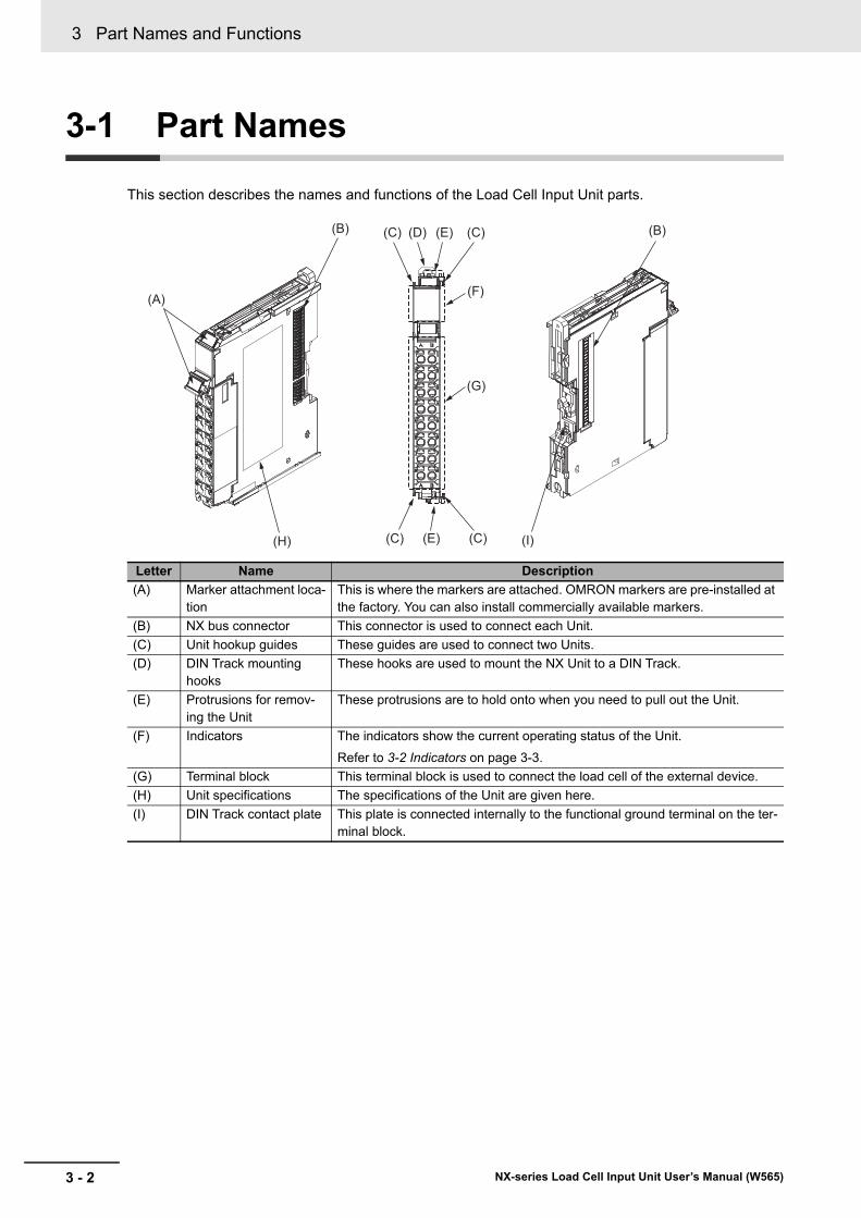
3 Part Names and Functions
3 - 2 NX-series Load Cell Input Unit User’s Manual (W565)
3-1 Part Names
This section describes the names and functions of the Load Cell Input Unit parts.
Letter Name Description
(A) Marker attachment loca-tion
This is where the markers are attached. OMRON markers are pre-installed at the factory. You can also install commercially available markers.
(B) NX bus connector This connector is used to connect each Unit.
(C) Unit hookup guides These guides are used to connect two Units.
(D) DIN Track mounting hooks
These hooks are used to mount the NX Unit to a DIN Track.
(E) Protrusions for remov-ing the Unit
These protrusions are to hold onto when you need to pull out the Unit.
(F) Indicators The indicators show the current operating status of the Unit.
Refer to 3-2 Indicators on page 3-3.
(G) Terminal block This terminal block is used to connect the load cell of the external device.
(H) Unit specifications The specifications of the Unit are given here.
(I) DIN Track contact plate This plate is connected internally to the functional ground terminal on the ter-minal block.
(C)(D)
(H)
(G)
(F)
(C)
(A)
(E)
(C) (I)(E)(C)
(B) (B)
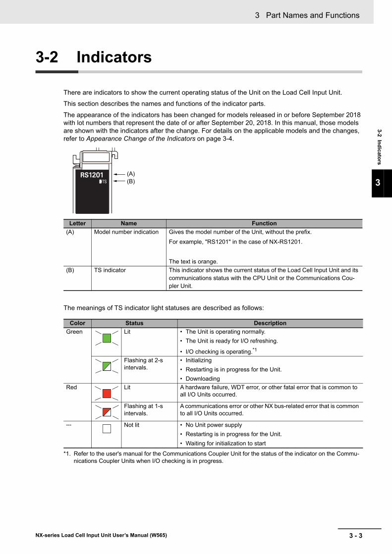
3 - 3
3 Part Names and Functions
NX-series Load Cell Input Unit User’s Manual (W565)
3-2 Ind
icators
3
3-2 Indicators
There are indicators to show the current operating status of the Unit on the Load Cell Input Unit.
This section describes the names and functions of the indicator parts.
The appearance of the indicators has been changed for models released in or before September 2018 with lot numbers that represent the date of or after September 20, 2018. In this manual, those models are shown with the indicators after the change. For details on the applicable models and the changes, refer to Appearance Change of the Indicators on page 3-4.
The meanings of TS indicator light statuses are described as follows:
Letter Name Function
(A) Model number indication Gives the model number of the Unit, without the prefix.
For example, "RS1201" in the case of NX-RS1201.
The text is orange.
(B) TS indicator This indicator shows the current status of the Load Cell Input Unit and its communications status with the CPU Unit or the Communications Cou-pler Unit.
Color Status Description
Green Lit • The Unit is operating normally.
• The Unit is ready for I/O refreshing.
• I/O checking is operating.*1
*1. Refer to the user's manual for the Communications Coupler Unit for the status of the indicator on the Commu-nications Coupler Units when I/O checking is in progress.
Flashing at 2-s intervals.
• Initializing
• Restarting is in progress for the Unit.
• Downloading
Red Lit A hardware failure, WDT error, or other fatal error that is common to all I/O Units occurred.
Flashing at 1-s intervals.
A communications error or other NX bus-related error that is common to all I/O Units occurred.
--- Not lit • No Unit power supply
• Restarting is in progress for the Unit.
• Waiting for initialization to start
(A)(B)
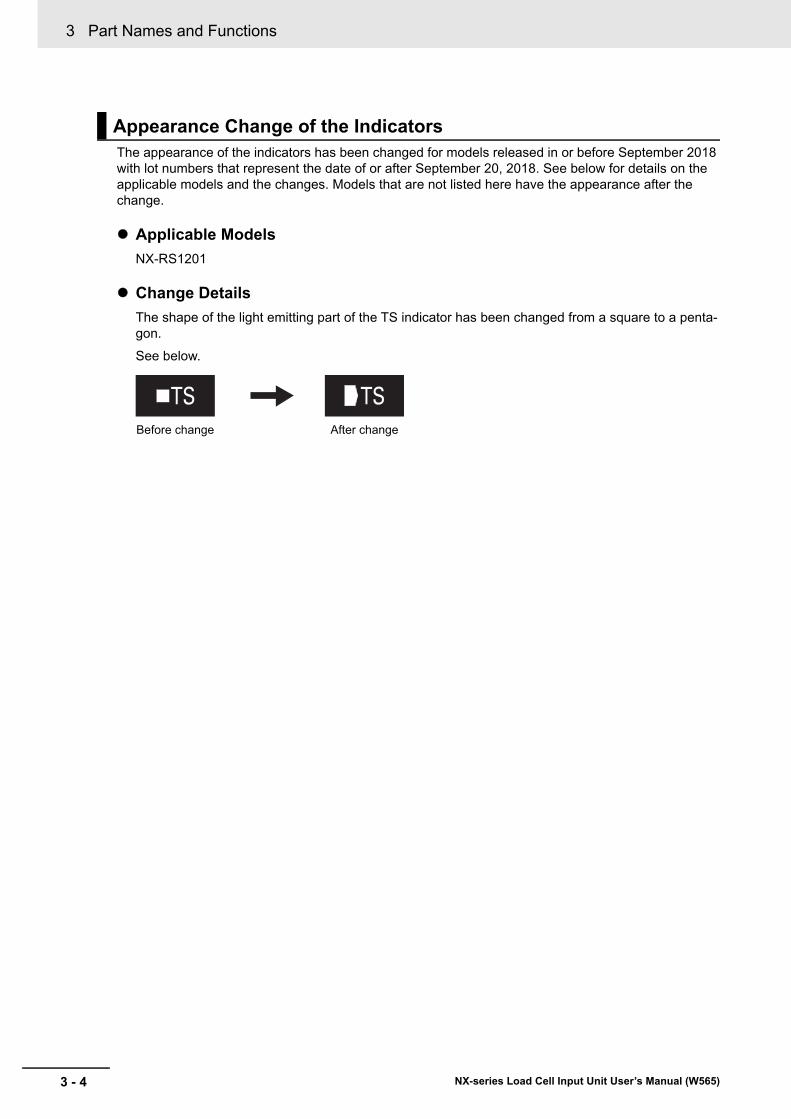
3 Part Names and Functions
3 - 4 NX-series Load Cell Input Unit User’s Manual (W565)
The appearance of the indicators has been changed for models released in or before September 2018 with lot numbers that represent the date of or after September 20, 2018. See below for details on the applicable models and the changes. Models that are not listed here have the appearance after the change.
Applicable Models
NX-RS1201
Change Details
The shape of the light emitting part of the TS indicator has been changed from a square to a penta-gon.
See below.
Appearance Change of the Indicators
Before change After change
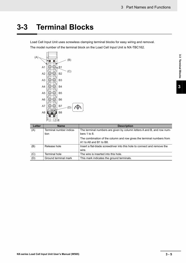
3 - 5
3 Part Names and Functions
NX-series Load Cell Input Unit User’s Manual (W565)
3-3 Termin
al Blo
cks
3
3-3 Terminal Blocks
Load Cell Input Unit uses screwless clamping terminal blocks for easy wiring and removal.
The model number of the terminal block on the Load Cell Input Unit is NX-TBC162.
Letter Name Description
(A) Terminal number indica-tion
The terminal numbers are given by column letters A and B, and row num-bers 1 to 8.
The combination of the column and row gives the terminal numbers from A1 to A8 and B1 to B8.
(B) Release hole Insert a flat-blade screwdriver into this hole to connect and remove the wire.
(C) Terminal hole The wire is inserted into this hole.
(D) Ground terminal mark This mark indicates the ground terminals.
(B)
(C)
(A)
A1
A2
A3
A4
A5
A6
A7
A8
B1
B2
B3
B4
B5
B6
B7
B8
(D)

3 Part Names and Functions
3 - 6 NX-series Load Cell Input Unit User’s Manual (W565)
4 - 1
4
NX-series Load Cell Input Unit User’s Manual (W565)
This section describes how to install and wire the Load Cell Input Unit.
4-1 Installing NX Units . . . . . . . . . . . . . . . . . . . . . . . . . . . . . . . . . . . . . . . . . . . . . 4-2
4-2 Wiring the Power Supply and Ground . . . . . . . . . . . . . . . . . . . . . . . . . . . . . 4-3
4-3 Wiring the Terminals . . . . . . . . . . . . . . . . . . . . . . . . . . . . . . . . . . . . . . . . . . . 4-44-3-1 Wiring the Screwless Clamping Terminal Blocks . . . . . . . . . . . . . . . . . . . . . . . 4-4
4-3-2 Checking the Wiring . . . . . . . . . . . . . . . . . . . . . . . . . . . . . . . . . . . . . . . . . . . . 4-19
4-4 Wiring the Connected External Devices . . . . . . . . . . . . . . . . . . . . . . . . . . 4-204-4-1 Terminal Block Arrangement . . . . . . . . . . . . . . . . . . . . . . . . . . . . . . . . . . . . . . 4-21
4-4-2 Wiring Example with 6-wire Connection . . . . . . . . . . . . . . . . . . . . . . . . . . . . . 4-22
4-4-3 Wiring Example with 4-wire Connection . . . . . . . . . . . . . . . . . . . . . . . . . . . . . 4-22
4-4-4 Wiring Example of Parallel Connection . . . . . . . . . . . . . . . . . . . . . . . . . . . . . . 4-23
Installation and Wiring
4 Installation and Wiring
4 - 2 NX-series Load Cell Input Unit User’s Manual (W565)
4-1 Installing NX Units
Refer to Installation in the hardware user’s manual for the connected CPU Unit or the user’s manual forthe connected Communications Coupler Unit for information on installing NX Units, including Load CellInput Units.
4 - 3
4 Installation and Wiring
NX-series Load Cell Input Unit User’s Manual (W565)
4-2 Wirin
g th
e Po
wer S
up
ply
and
Gro
un
d
4
4-2 Wiring the Power Supply and Ground
There is the following one type of power supply that supplies power to the Load Cell Input Unit.
NX Unit power supply
The method for supplying power to the Load Cell Input Unit and the wiring and grounding methods depend on the specifications for the CPU Unit or Slave Terminal to which NX Units are connected. Refer to Designing the Power Supply System and Wiring in the hardware user’s manual for the con-nected CPU Unit and the user’s manual for the Communications Coupler Unit for details on the method for supplying power to the Load Cell Input Unit and the wiring and grounding methods.
Refer to 4-4 Wiring the Connected External Devices on page 4-20 for information on connecting the shield wire when you connect the Load Cell Input Unit to an external device.
Precautions for Safe Use
The I/O power supply current for the CPU Rack with an NX-series CPU Unit should be within the range specified for the CPU Unit model. For example, use the NX1P2 CPU Unit with a cur-rent of 4 A or less. Using the currents that are outside of the specifications may cause failure or damage. Refer to the user’s manual for the connected CPU Unit for the I/O power supply cur-rent for the CPU Unit model.
Additional Information
• It is not necessary to supply I/O power to the Load Cell Input Unit. The Load Cell Input Unit operates with the NX Unit power supply and supplies excitation voltage to the load cell.
• The terminal block on a Load Cell Input Unit has a functional ground terminal and you must ground it. However, if the DIN Track on which the CPU Rack and Slave Terminal are installed is made of steel and the surface is not treated using an insulating material, you can omit grounding the functional ground terminal on the Load Cell Input Unit. This is because the functional ground terminal on the Load Cell Input Unit is electrically connected to the DIN Track through the DIN Track contact plate. Refer to Wiring in the hardware user’s manual for the connected CPU Unit for details on grounding the CPU Rack. Refer to Wiring in the user’s manual for the connected Communi-cations Coupler Unit for details on grounding the Slave Terminal.
4 Installation and Wiring
4 - 4 NX-series Load Cell Input Unit User’s Manual (W565)
4-3 Wiring the Terminals
This section describes how to wire the terminals on the Load Cell Input Unit.
This section describes how to connect wires to the screwless clamping terminal block, the installation and removing methods, and functions for preventing incorrect attachment.
You can connect ferrules that are attached to the twisted wires to the screwless clamping terminal block. You can also connect the twisted wires or the solid wires to the screwless clamping terminal block. If you connect the ferrules, all you need to do to connect the wires is to insert the ferrules into the terminal holes.
The terminals to be wired are as follows.
• I/O terminals
The wires that you can connect to the screwless clamping terminal block are twisted wires, solid wires, and ferrules that are attached to the twisted wires. The following section describes the dimensions and processed methods for applicable wires.
Recommended Wires
The following table gives the recommended wires.
Make sure that the voltages and currents that are input to the Units and slaves are within the speci-fied ranges.
Inputting voltages or currents that are outside of the specified ranges may cause accidents or fire.
4-3-1 Wiring the Screwless Clamping Terminal Blocks
Wiring Terminals
Applicable Wires
Wiring part Specification
Wires Shielded cable
Size: AWG28 to 16 (0.08 to 1.5 mm2)
WARNING

4 - 5
4 Installation and Wiring
NX-series Load Cell Input Unit User’s Manual (W565)
4-3 Wirin
g th
e Termin
als
4
4-3-1 Wiring the S
crewless C
lamping Te
rminal B
locks
Dimensions of Wires Connected to the Terminal Block
The dimensions of wires that you can connect into the terminal holes of the screwless clamping ter-minal block are as in the figure below.
Process the applicable wires that are specified in the following description to apply the dimensions.
Using Ferrules
If you use ferrules, attach the twisted wires to them.
Observe the application instructions for your ferrules for the wire stripping length when attaching fer-rules.
Always use plated one-pin ferrules. Do not use unplated ferrules or two-pin ferrules.
The applicable ferrules, wires, and crimping tools are listed in the following table.
Terminal types
Manufac-turer
Ferrule model
Applica-ble wire
(mm2 (AWG))
Crimping tool
Terminals other than ground ter-minals
Phoenix Contact
AI0,34-8 0.34 (#22) Phoenix Contact (The figure in parentheses is the applicable wire size.)
CRIMPFOX 6 (0.25 to 6 mm2, AWG24 to 10)
AI0,5-8 0.5 (#20)
AI0,5-10
AI0,75-8 0.75 (#18)
AI0,75-10
AI1,0-8 1.0 (#18)
AI1,0-10
AI1,5-8 1.5 (#16)
AI1,5-10
Ground ter-minals
AI2,5-10 2.0 *1
*1. Some AWG14 wires exceed 2.0 mm2 and cannot be used in the screwless clamping terminal block.
Terminals other than ground ter-minals
Weidmuller H0.14/12 0.14 (#26) Weidmuller (The figure in parentheses is the appli-cable wire size.)
PZ6 Roto (0.14 to 6 mm2, AWG26 to 10)
H0.25/12 0.25 (#24)
H0.34/12 0.34 (#22)
H0.5/14 0.5 (#20)
H0.5/16
H0.75/14 0.75 (#18)
H0.75/16
H1.0/14 1.0 (#18)
H1.0/16
H1.5/14 1.5 (#16)
H1.5/16
1.6 mm max. (Terminals other than ground terminals)2.0 mm max. (Ground terminals)
2.4 mm max. (Terminals other than ground terminals)2.7 mm max. (Ground terminals)
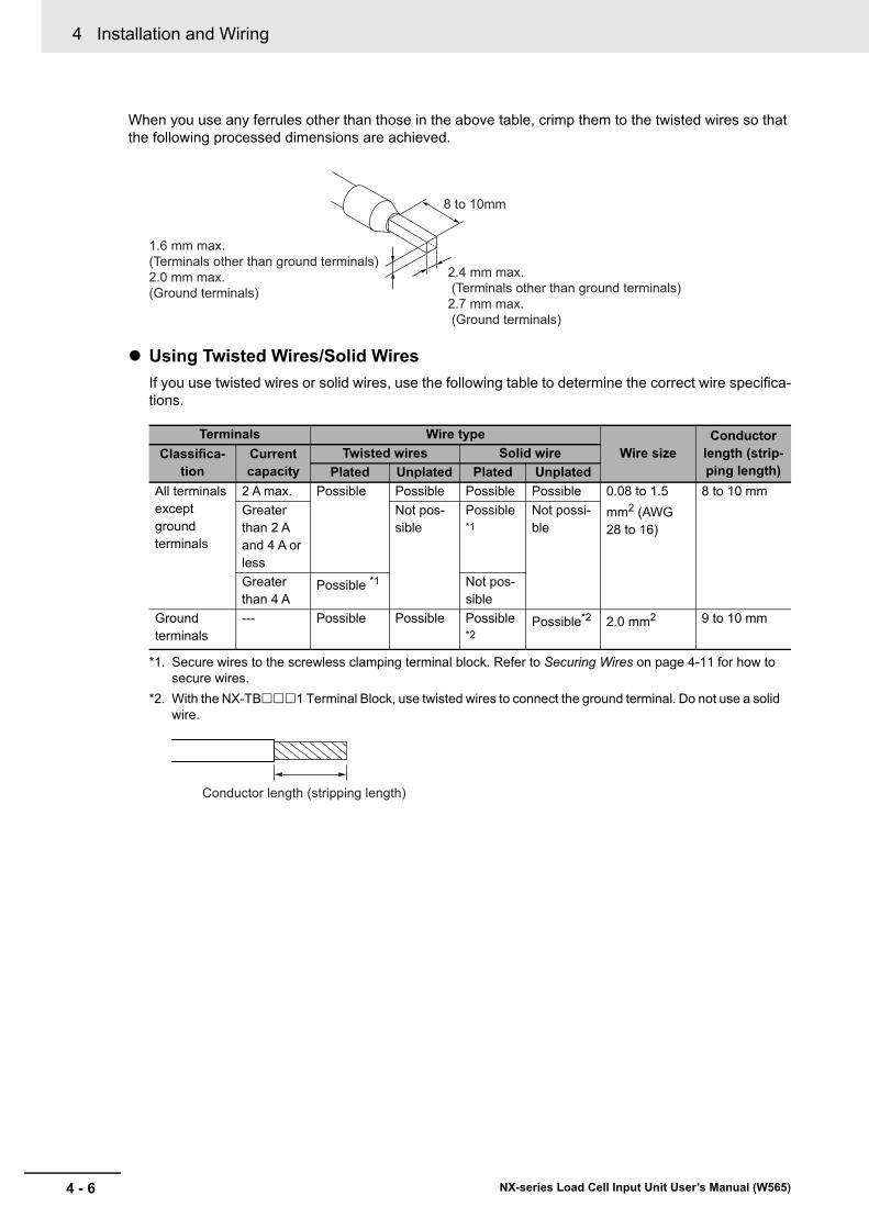
4 Installation and Wiring
4 - 6 NX-series Load Cell Input Unit User’s Manual (W565)
When you use any ferrules other than those in the above table, crimp them to the twisted wires so that the following processed dimensions are achieved.
Using Twisted Wires/Solid Wires
If you use twisted wires or solid wires, use the following table to determine the correct wire specifica-tions.
Terminals Wire type
Wire sizeConductor
length (strip-ping length)
Classifica-tion
Current capacity
Twisted wires Solid wire
Plated Unplated Plated Unplated
All terminals except ground terminals
2 A max. Possible Possible Possible Possible 0.08 to 1.5
mm2 (AWG 28 to 16)
8 to 10 mm
Greater than 2 A and 4 A or less
Not pos-sible
Possible *1
Not possi-ble
Greater than 4 A
Possible *1
*1. Secure wires to the screwless clamping terminal block. Refer to Securing Wires on page 4-11 for how to secure wires.
Not pos-sible
Ground terminals
--- Possible Possible Possible *2
*2. With the NX-TB1 Terminal Block, use twisted wires to connect the ground terminal. Do not use a solid wire.
Possible*2 2.0 mm2 9 to 10 mm
8 to 10mm
2.4 mm max. (Terminals other than ground terminals)2.7 mm max. (Ground terminals)
1.6 mm max. (Terminals other than ground terminals)2.0 mm max. (Ground terminals)
Conductor length (stripping length)
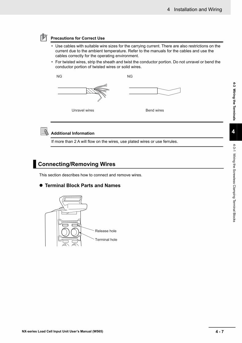
4 - 7
4 Installation and Wiring
NX-series Load Cell Input Unit User’s Manual (W565)
4-3 Wirin
g th
e Termin
als
4
4-3-1 Wiring the S
crewless C
lamping Te
rminal B
locks
Precautions for Correct Use
• Use cables with suitable wire sizes for the carrying current. There are also restrictions on the current due to the ambient temperature. Refer to the manuals for the cables and use the cables correctly for the operating environment.
• For twisted wires, strip the sheath and twist the conductor portion. Do not unravel or bend the conductor portion of twisted wires or solid wires.
Additional Information
If more than 2 A will flow on the wires, use plated wires or use ferrules.
This section describes how to connect and remove wires.
Terminal Block Parts and Names
Connecting/Removing Wires
Unravel wires Bend wires
NG NG
Terminal hole
Release hole
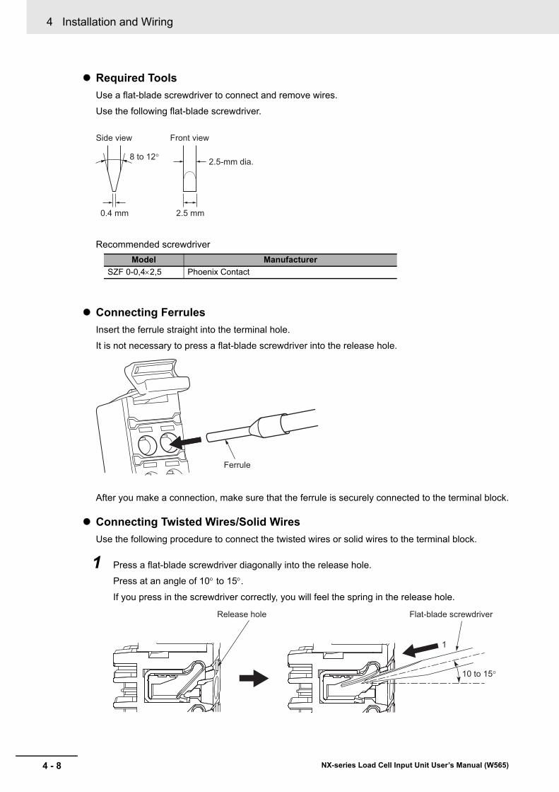
4 Installation and Wiring
4 - 8 NX-series Load Cell Input Unit User’s Manual (W565)
Required Tools
Use a flat-blade screwdriver to connect and remove wires.
Use the following flat-blade screwdriver.
Recommended screwdriver
Connecting Ferrules
Insert the ferrule straight into the terminal hole.
It is not necessary to press a flat-blade screwdriver into the release hole.
After you make a connection, make sure that the ferrule is securely connected to the terminal block.
Connecting Twisted Wires/Solid Wires
Use the following procedure to connect the twisted wires or solid wires to the terminal block.
1 Press a flat-blade screwdriver diagonally into the release hole.
Press at an angle of 10 to 15.
If you press in the screwdriver correctly, you will feel the spring in the release hole.
Model Manufacturer
SZF 0-0,42,5 Phoenix Contact
2.5 mm0.4 mm
Front view
8 to 12°
Side view
2.5-mm dia.
Ferrule
1
10 to 15°
Release hole Flat-blade screwdriver
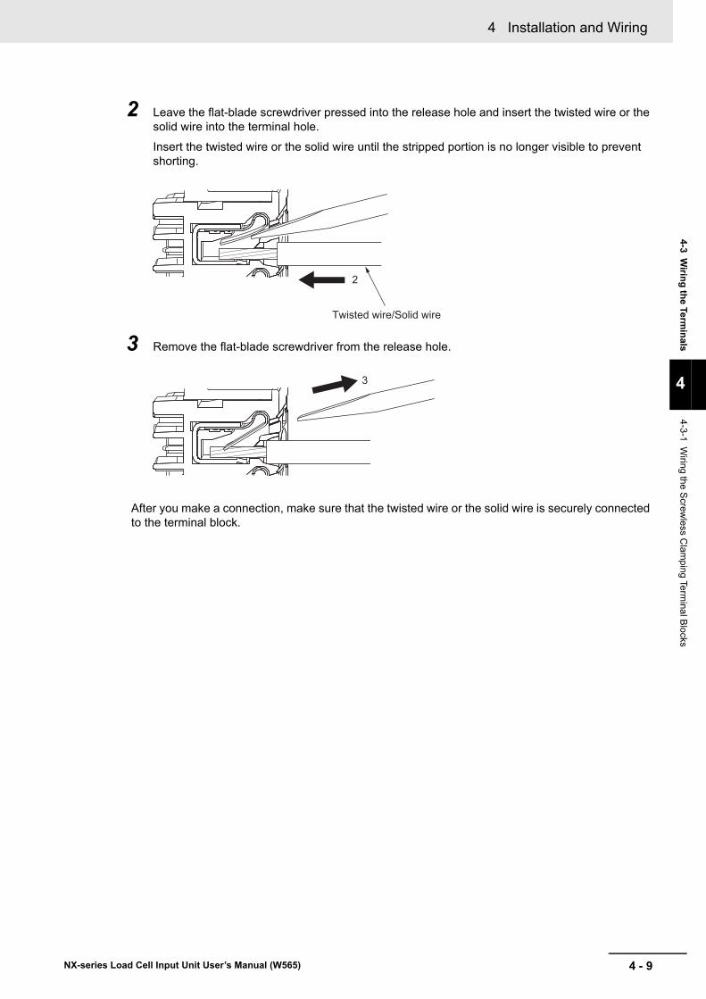
4 - 9
4 Installation and Wiring
NX-series Load Cell Input Unit User’s Manual (W565)
4-3 Wirin
g th
e Termin
als
4
4-3-1 Wiring the S
crewless C
lamping Te
rminal B
locks
2 Leave the flat-blade screwdriver pressed into the release hole and insert the twisted wire or the solid wire into the terminal hole.
Insert the twisted wire or the solid wire until the stripped portion is no longer visible to prevent shorting.
3 Remove the flat-blade screwdriver from the release hole.
After you make a connection, make sure that the twisted wire or the solid wire is securely connected to the terminal block.
2
Twisted wire/Solid wire
3
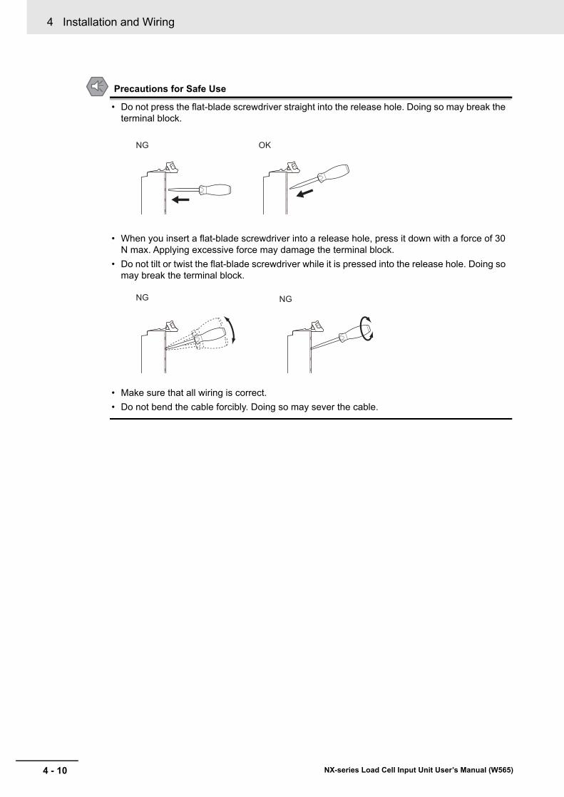
4 Installation and Wiring
4 - 10 NX-series Load Cell Input Unit User’s Manual (W565)
Precautions for Safe Use
• Do not press the flat-blade screwdriver straight into the release hole. Doing so may break the terminal block.
• When you insert a flat-blade screwdriver into a release hole, press it down with a force of 30 N max. Applying excessive force may damage the terminal block.
• Do not tilt or twist the flat-blade screwdriver while it is pressed into the release hole. Doing so may break the terminal block.
• Make sure that all wiring is correct.
• Do not bend the cable forcibly. Doing so may sever the cable.
NG OK
NG NG
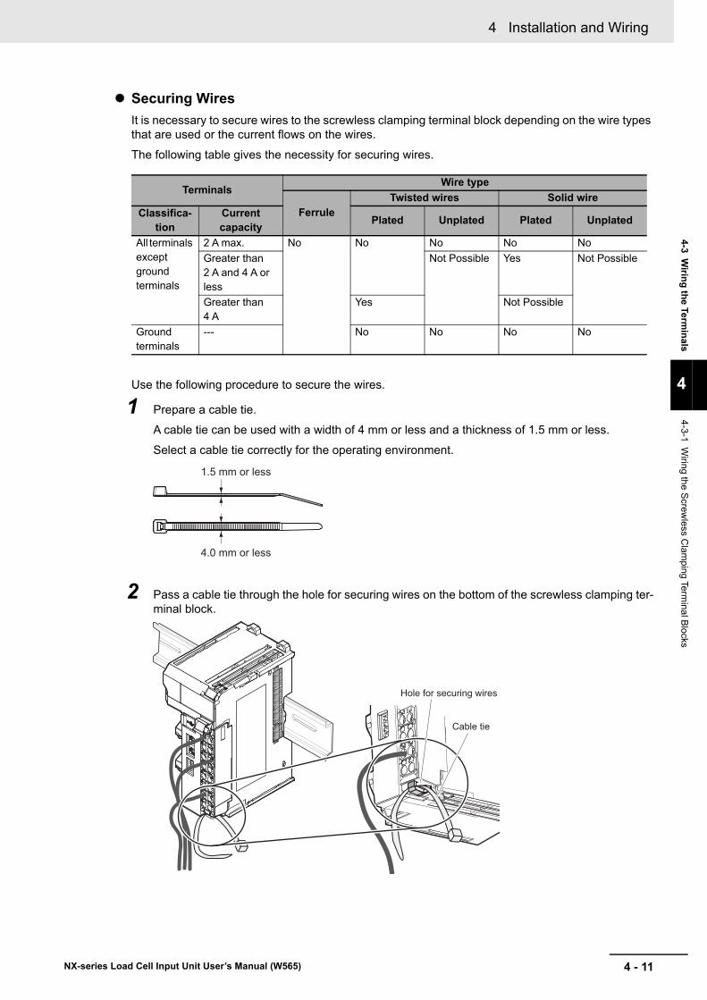
4 - 11
4 Installation and Wiring
NX-series Load Cell Input Unit User’s Manual (W565)
4-3 Wirin
g th
e Termin
als
4
4-3-1 Wiring the S
crewless C
lamping Te
rminal B
locks
Securing Wires
It is necessary to secure wires to the screwless clamping terminal block depending on the wire types that are used or the current flows on the wires.
The following table gives the necessity for securing wires.
Use the following procedure to secure the wires.
1 Prepare a cable tie.
A cable tie can be used with a width of 4 mm or less and a thickness of 1.5 mm or less.
Select a cable tie correctly for the operating environment.
2 Pass a cable tie through the hole for securing wires on the bottom of the screwless clamping ter-minal block.
TerminalsWire type
FerruleTwisted wires Solid wire
Classifica-tion
Current capacity
Plated Unplated Plated Unplated
All terminals except ground terminals
2 A max. No No No No No
Greater than 2 A and 4 A or less
Not Possible Yes Not Possible
Greater than 4 A
Yes Not Possible
Ground terminals
--- No No No No
1.5 mm or less
4.0 mm or less
Hole for securing wires
Cable tie
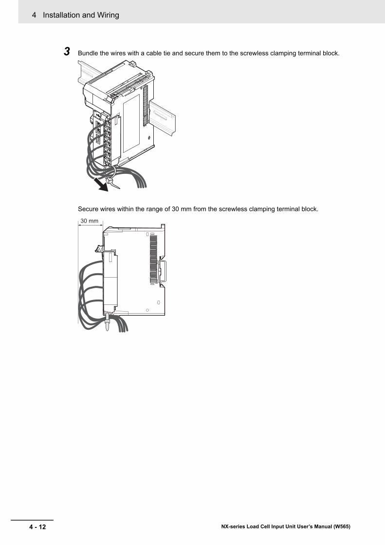
4 Installation and Wiring
4 - 12 NX-series Load Cell Input Unit User’s Manual (W565)
3 Bundle the wires with a cable tie and secure them to the screwless clamping terminal block.
Secure wires within the range of 30 mm from the screwless clamping terminal block.
30 mm
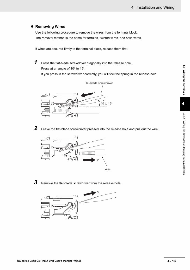
4 - 13
4 Installation and Wiring
NX-series Load Cell Input Unit User’s Manual (W565)
4-3 Wirin
g th
e Termin
als
4
4-3-1 Wiring the S
crewless C
lamping Te
rminal B
locks
Removing Wires
Use the following procedure to remove the wires from the terminal block.
The removal method is the same for ferrules, twisted wires, and solid wires.
If wires are secured firmly to the terminal block, release them first.
1 Press the flat-blade screwdriver diagonally into the release hole.
Press at an angle of 10 to 15.
If you press in the screwdriver correctly, you will feel the spring in the release hole.
2 Leave the flat-blade screwdriver pressed into the release hole and pull out the wire.
3 Remove the flat-blade screwdriver from the release hole.
1
10 to 15°
Flat-blade screwdriver
2
Wire
3
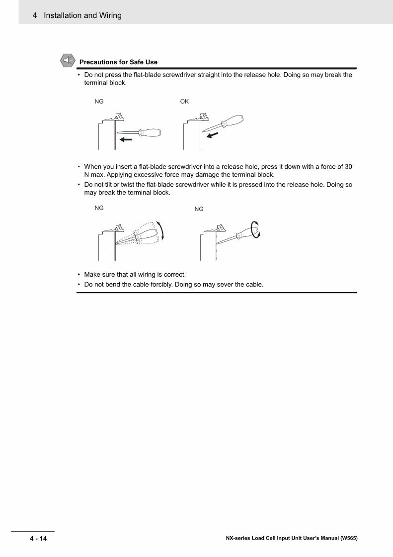
4 Installation and Wiring
4 - 14 NX-series Load Cell Input Unit User’s Manual (W565)
Precautions for Safe Use
• Do not press the flat-blade screwdriver straight into the release hole. Doing so may break the terminal block.
• When you insert a flat-blade screwdriver into a release hole, press it down with a force of 30 N max. Applying excessive force may damage the terminal block.
• Do not tilt or twist the flat-blade screwdriver while it is pressed into the release hole. Doing so may break the terminal block.
• Make sure that all wiring is correct.
• Do not bend the cable forcibly. Doing so may sever the cable.
NG OK
NG NG
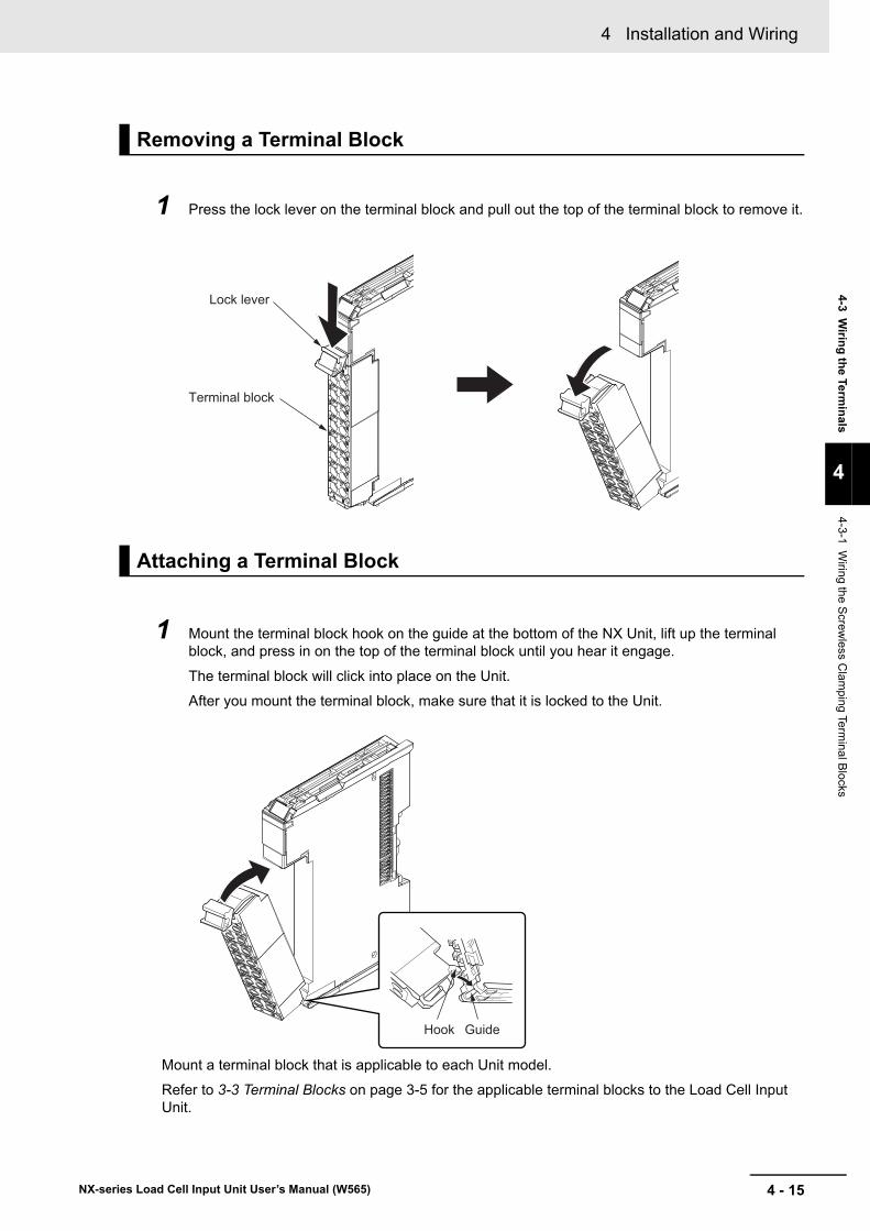
4 - 15
4 Installation and Wiring
NX-series Load Cell Input Unit User’s Manual (W565)
4-3 Wirin
g th
e Termin
als
4
4-3-1 Wiring the S
crewless C
lamping Te
rminal B
locks
1 Press the lock lever on the terminal block and pull out the top of the terminal block to remove it.
1 Mount the terminal block hook on the guide at the bottom of the NX Unit, lift up the terminal block, and press in on the top of the terminal block until you hear it engage.
The terminal block will click into place on the Unit.
After you mount the terminal block, make sure that it is locked to the Unit.
Mount a terminal block that is applicable to each Unit model.
Refer to 3-3 Terminal Blocks on page 3-5 for the applicable terminal blocks to the Load Cell Input Unit.
Removing a Terminal Block
Attaching a Terminal Block
Lock lever
Terminal block
GuideHook
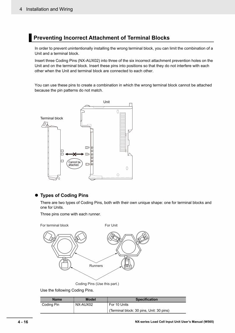
4 Installation and Wiring
4 - 16 NX-series Load Cell Input Unit User’s Manual (W565)
In order to prevent unintentionally installing the wrong terminal block, you can limit the combination of a Unit and a terminal block.
Insert three Coding Pins (NX-AUX02) into three of the six incorrect attachment prevention holes on the Unit and on the terminal block. Insert these pins into positions so that they do not interfere with each other when the Unit and terminal block are connected to each other.
You can use these pins to create a combination in which the wrong terminal block cannot be attached because the pin patterns do not match.
Types of Coding Pins
There are two types of Coding Pins, both with their own unique shape: one for terminal blocks and one for Units.
Three pins come with each runner.
Use the following Coding Pins.
Preventing Incorrect Attachment of Terminal Blocks
Name Model Specification
Coding Pin NX-AUX02 For 10 Units
(Terminal block: 30 pins, Unit: 30 pins)
Terminal block
Unit
Cannot be attached.
For terminal block For Unit
Coding Pins (Use this part.)
Runners
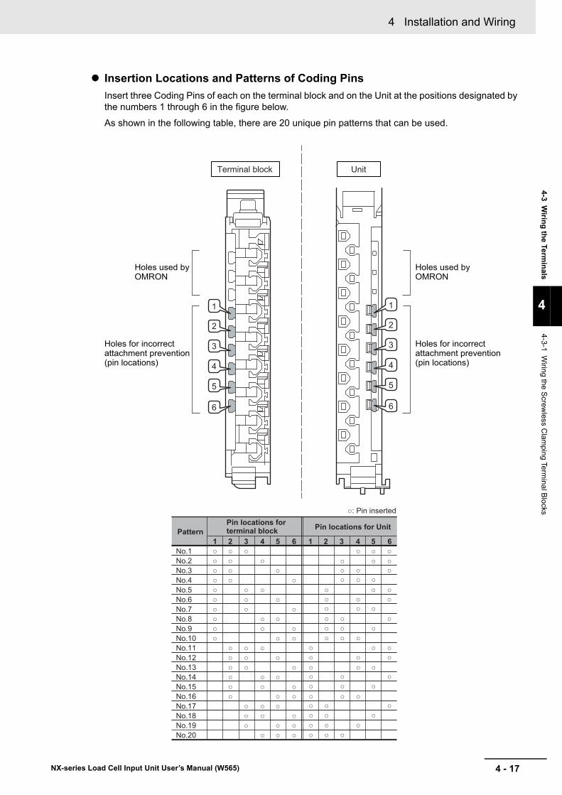
4 - 17
4 Installation and Wiring
NX-series Load Cell Input Unit User’s Manual (W565)
4-3 Wirin
g th
e Termin
als
4
4-3-1 Wiring the S
crewless C
lamping Te
rminal B
locks
Insertion Locations and Patterns of Coding Pins
Insert three Coding Pins of each on the terminal block and on the Unit at the positions designated by the numbers 1 through 6 in the figure below.
As shown in the following table, there are 20 unique pin patterns that can be used.
Pin locations for terminal block
: Pin inserted
Terminal block Unit
1 2 3 4 5 6No.1 No.2 No.3 No.4 No.5 No.6 No.7 No.8 No.9 No.10
No.11 No.12 No.13 No.14 No.15 No.16 No.17 No.18 No.19 No.20
1 2 3 4 5 6
1
2
3
4
5
6
1
2
3
4
5
6
Holes used byOMRON
Holes for incorrectattachment prevention(pin locations)
Pin locations for UnitPattern
Holes used byOMRON
Holes for incorrectattachment prevention(pin locations)
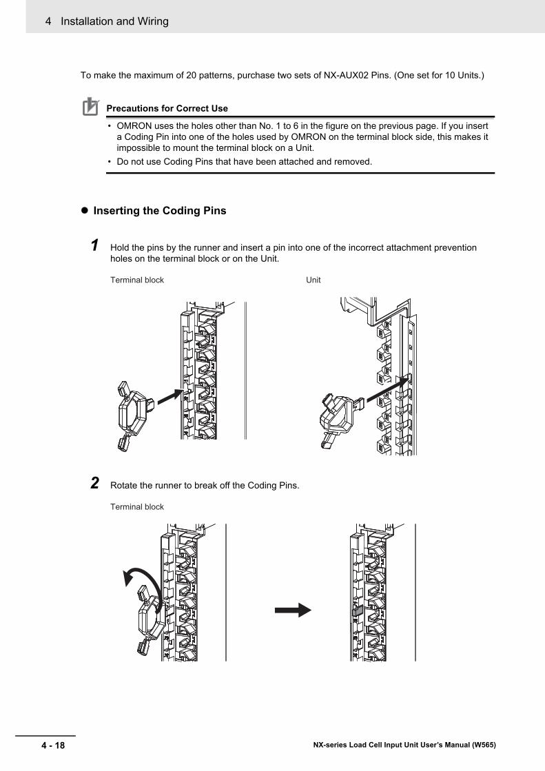
4 Installation and Wiring
4 - 18 NX-series Load Cell Input Unit User’s Manual (W565)
To make the maximum of 20 patterns, purchase two sets of NX-AUX02 Pins. (One set for 10 Units.)
Precautions for Correct Use
• OMRON uses the holes other than No. 1 to 6 in the figure on the previous page. If you insert a Coding Pin into one of the holes used by OMRON on the terminal block side, this makes it impossible to mount the terminal block on a Unit.
• Do not use Coding Pins that have been attached and removed.
Inserting the Coding Pins
1 Hold the pins by the runner and insert a pin into one of the incorrect attachment prevention holes on the terminal block or on the Unit.
2 Rotate the runner to break off the Coding Pins.
Terminal block Unit
Terminal block
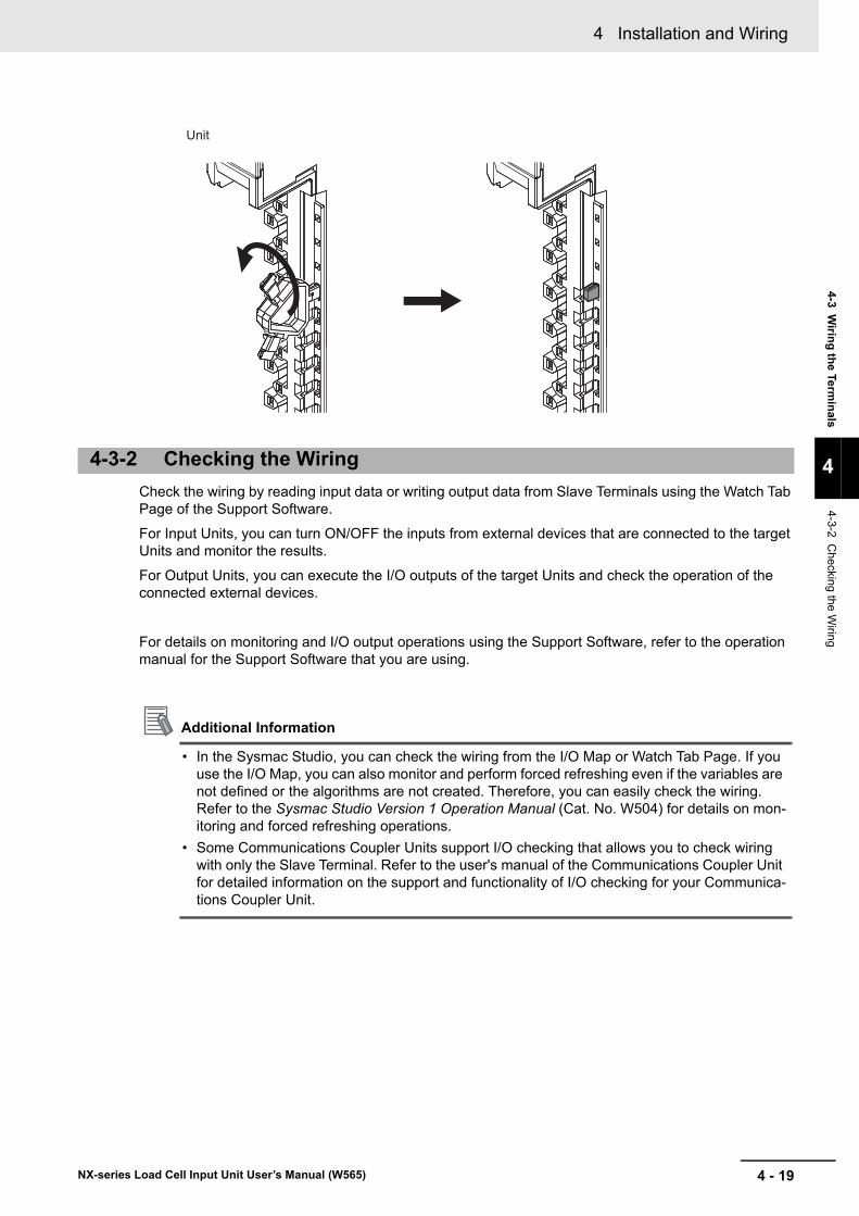
4 - 19
4 Installation and Wiring
NX-series Load Cell Input Unit User’s Manual (W565)
4-3 Wirin
g th
e Termin
als
4
4-3-2 Checking the W
iring
Check the wiring by reading input data or writing output data from Slave Terminals using the Watch Tab Page of the Support Software.
For Input Units, you can turn ON/OFF the inputs from external devices that are connected to the target Units and monitor the results.
For Output Units, you can execute the I/O outputs of the target Units and check the operation of the connected external devices.
For details on monitoring and I/O output operations using the Support Software, refer to the operation manual for the Support Software that you are using.
Additional Information
• In the Sysmac Studio, you can check the wiring from the I/O Map or Watch Tab Page. If you use the I/O Map, you can also monitor and perform forced refreshing even if the variables are not defined or the algorithms are not created. Therefore, you can easily check the wiring. Refer to the Sysmac Studio Version 1 Operation Manual (Cat. No. W504) for details on mon-itoring and forced refreshing operations.
• Some Communications Coupler Units support I/O checking that allows you to check wiring with only the Slave Terminal. Refer to the user's manual of the Communications Coupler Unit for detailed information on the support and functionality of I/O checking for your Communica-tions Coupler Unit.
4-3-2 Checking the Wiring
Unit
4 Installation and Wiring
4 - 20 NX-series Load Cell Input Unit User’s Manual (W565)
4-4 Wiring the Connected External Devices
This section provides information on wiring the Load Cell Input Unit to the connected external devices.
You can connect the Load Cell Input Unit to the load cell with a 6-wire or 4-wire connection. We recom-mend that you use a 6-wire connection for connecting the load cell with the Load Cell Input Unit to achieve high-precision measurements.
Precautions for Safe Use
• Use a shielded cable to connect to the load cell. Connect the shield wire to the SHLD termi-nal on the Load Cell Input Unit.
• Ground the functional ground terminal on the Load Cell Input Unit to 100 Ω or less.
Precautions for Correct Use
• We recommend that you use a 6-wire connection for connecting the load cell with the Load Cell Input Unit to achieve high-precision measurements. When you use a 4-wire connection, the measurement resolution of wiring resistance is deteriorated due to temperature changes.
• Keep the wiring resistance from the load cell to the Load Cell Input Unit to 5 Ω or less while in use.
• Wire the cable that connects the load cell and the Load Cell Input Unit separately from AC power supply lines or power lines in order to avoid the effects of the noise. Do not place such lines in the same duct.
• Insert a noise filter into the power supply input section if noise may overlap from power sup-ply lines when using the same power supply to power an electrical welder or an electric dis-charge machine, or there is a high-frequency source nearby.
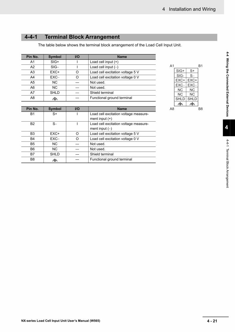
4 - 21
4 Installation and Wiring
NX-series Load Cell Input Unit User’s Manual (W565)
4-4 W
iring
the C
on
nected
Extern
al Devices
4
4-4-1 Terminal B
lock Arrangem
ent
The table below shows the terminal block arrangement of the Load Cell Input Unit.
4-4-1 Terminal Block Arrangement
Pin No. Symbol I/O Name
A1 SIG+ I Load cell input (+)
A2 SIG I Load cell input ()
A3 EXC+ O Load cell excitation voltage 5 V
A4 EXC O Load cell excitation voltage 0 V
A5 NC --- Not used.
A6 NC --- Not used.
A7 SHLD --- Shield terminal
A8 --- Functional ground terminal
Pin No. Symbol I/O Name
B1 S+ I Load cell excitation voltage measure-ment input (+)
B2 S I Load cell excitation voltage measure-ment input ()
B3 EXC+ O Load cell excitation voltage 5 V
B4 EXC O Load cell excitation voltage 0 V
B5 NC --- Not used.
B6 NC --- Not used.
B7 SHLD --- Shield terminal
B8 --- Functional ground terminal
SHLDNC
SHLD
EXC− EXC−
SIG- S−EXC+ EXC+
SIG+ S+
NCNC NC
A1 B1
A8 B8
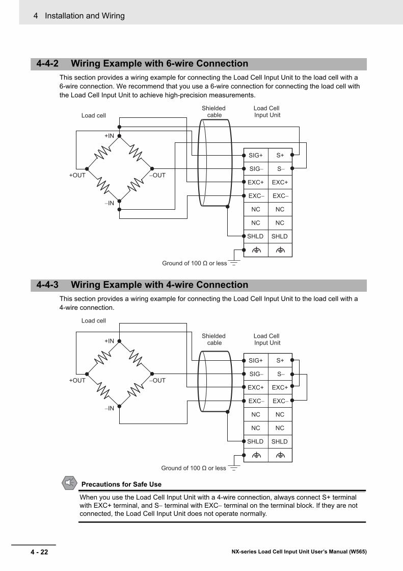
4 Installation and Wiring
4 - 22 NX-series Load Cell Input Unit User’s Manual (W565)
This section provides a wiring example for connecting the Load Cell Input Unit to the load cell with a 6-wire connection. We recommend that you use a 6-wire connection for connecting the load cell with the Load Cell Input Unit to achieve high-precision measurements.
This section provides a wiring example for connecting the Load Cell Input Unit to the load cell with a 4-wire connection.
Precautions for Safe Use
When you use the Load Cell Input Unit with a 4-wire connection, always connect S+ terminal with EXC+ terminal, and S terminal with EXC terminal on the terminal block. If they are not connected, the Load Cell Input Unit does not operate normally.
4-4-2 Wiring Example with 6-wire Connection
4-4-3 Wiring Example with 4-wire Connection
Load cell
+IN
−IN
−OUT+OUT
Shielded cable
Load Cell Input Unit
SIG+ S+
SIG− S−
EXC+ EXC+
EXC− EXC−
NC NC
NC NC
SHLD SHLD
Ground of 100 Ω or less
Load cell
+IN
−IN
−OUT+OUT
Shielded cable
Load Cell Input Unit
SIG+ S+
SIG− S−
EXC+ EXC+
EXC− EXC−
NC NC
NC NC
SHLD SHLD
Ground of 100 Ω or less
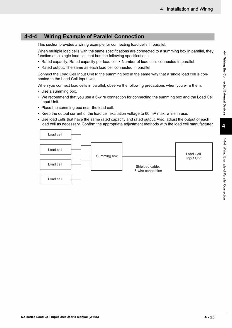
4 - 23
4 Installation and Wiring
NX-series Load Cell Input Unit User’s Manual (W565)
4-4 W
iring
the C
on
nected
Extern
al Devices
4
4-4-4 Wiring E
xam
ple of Pa
rallel Conne
ction
This section provides a wiring example for connecting load cells in parallel.
When multiple load cells with the same specifications are connected to a summing box in parallel, they function as a single load cell that has the following specifications.
• Rated capacity: Rated capacity per load cell × Number of load cells connected in parallel
• Rated output: The same as each load cell connected in parallel
Connect the Load Cell Input Unit to the summing box in the same way that a single load cell is con-nected to the Load Cell Input Unit.
When you connect load cells in parallel, observe the following precautions when you wire them.
• Use a summing box.
• We recommend that you use a 6-wire connection for connecting the summing box and the Load Cell Input Unit.
• Place the summing box near the load cell.
• Keep the output current of the load cell excitation voltage to 60 mA max. while in use.
• Use load cells that have the same rated capacity and rated output. Also, adjust the output of each load cell as necessary. Confirm the appropriate adjustment methods with the load cell manufacturer.
4-4-4 Wiring Example of Parallel Connection
Load Cell Input UnitSumming box
Shielded cable, 6-wire connection
Load cell
Load cell
Load cell
Load cell

4 Installation and Wiring
4 - 24 NX-series Load Cell Input Unit User’s Manual (W565)
5 - 1
5
NX-series Load Cell Input Unit User’s Manual (W565)
This section describes the types and functions of I/O refreshing for the Load Cell Input Unit.
5-1 I/O Refreshing . . . . . . . . . . . . . . . . . . . . . . . . . . . . . . . . . . . . . . . . . . . . . . . . . 5-25-1-1 I/O Refreshing from CPU Units to NX Units . . . . . . . . . . . . . . . . . . . . . . . . . . . 5-2
5-1-2 I/O Refreshing from CPU Units or Industrial PCs to Slave Terminal . . . . . . . . . 5-3
5-1-3 Calculating the I/O Response Times of NX Units . . . . . . . . . . . . . . . . . . . . . . . 5-4
5-2 I/O Refreshing Methods . . . . . . . . . . . . . . . . . . . . . . . . . . . . . . . . . . . . . . . . . 5-55-2-1 Types of I/O Refreshing Methods . . . . . . . . . . . . . . . . . . . . . . . . . . . . . . . . . . . 5-5
5-2-2 Setting the I/O Refreshing Methods . . . . . . . . . . . . . . . . . . . . . . . . . . . . . . . . . 5-6
5-2-3 Restrictions in Refresh Cycles . . . . . . . . . . . . . . . . . . . . . . . . . . . . . . . . . . . . . 5-7
5-2-4 I/O Refreshing Method Operation . . . . . . . . . . . . . . . . . . . . . . . . . . . . . . . . . . . 5-8
I/O Refreshing
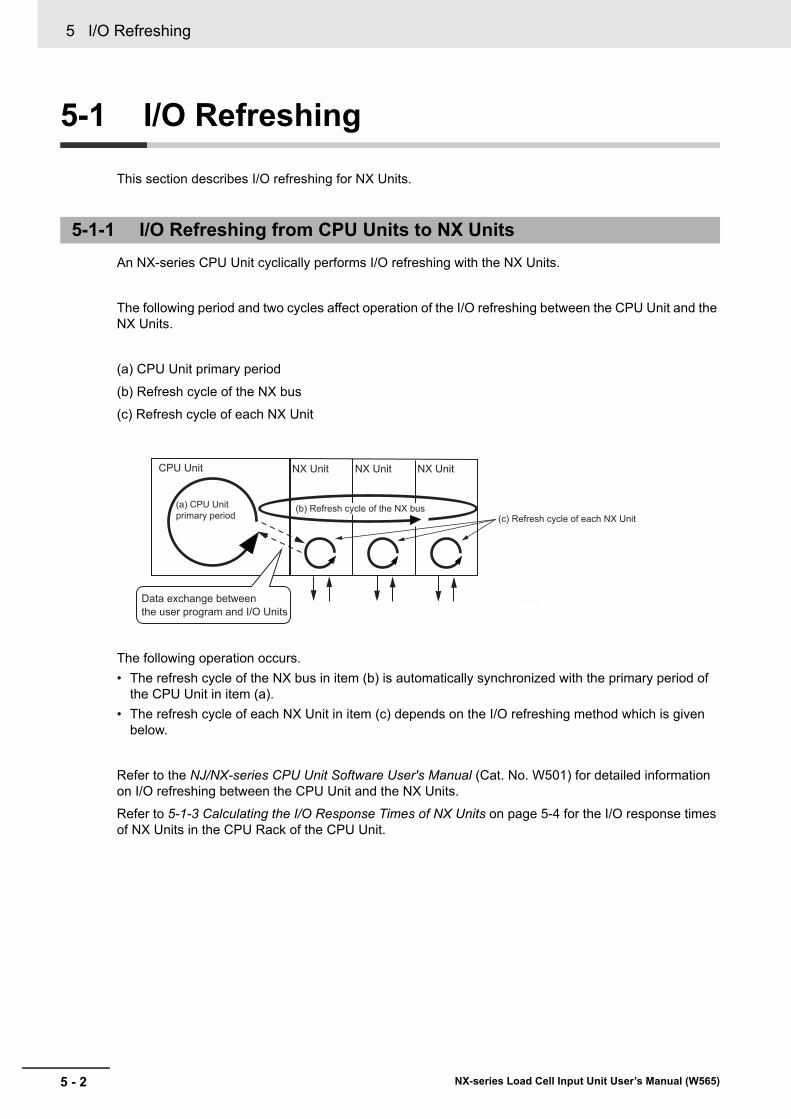
5 I/O Refreshing
5 - 2 NX-series Load Cell Input Unit User’s Manual (W565)
5-1 I/O Refreshing
This section describes I/O refreshing for NX Units.
An NX-series CPU Unit cyclically performs I/O refreshing with the NX Units.
The following period and two cycles affect operation of the I/O refreshing between the CPU Unit and the NX Units.
(a) CPU Unit primary period
(b) Refresh cycle of the NX bus
(c) Refresh cycle of each NX Unit
The following operation occurs.
• The refresh cycle of the NX bus in item (b) is automatically synchronized with the primary period of the CPU Unit in item (a).
• The refresh cycle of each NX Unit in item (c) depends on the I/O refreshing method which is given below.
Refer to the NJ/NX-series CPU Unit Software User's Manual (Cat. No. W501) for detailed information on I/O refreshing between the CPU Unit and the NX Units.
Refer to 5-1-3 Calculating the I/O Response Times of NX Units on page 5-4 for the I/O response times of NX Units in the CPU Rack of the CPU Unit.
5-1-1 I/O Refreshing from CPU Units to NX Units
CPU Unit
(b) Refresh cycle of the NX bus
NX UnitNX Unit
(c) Refresh cycle of each NX Unit
NX Unit
(a) CPU Unit primary period
Data exchange between the user program and I/O Units
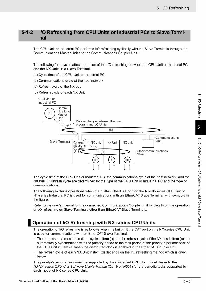
5 - 3
5 I/O Refreshing
NX-series Load Cell Input Unit User’s Manual (W565)
5-1 I/O R
efreshin
g
5
5-1-2 I/O R
efreshing from C
PU
Units or Industrial P
Cs to S
lave Term
inal
The CPU Unit or Industrial PC performs I/O refreshing cyclically with the Slave Terminals through the Communications Master Unit and the Communications Coupler Unit.
The following four cycles affect operation of the I/O refreshing between the CPU Unit or Industrial PC and the NX Units in a Slave Terminal:
(a) Cycle time of the CPU Unit or Industrial PC
(b) Communications cycle of the host network
(c) Refresh cycle of the NX bus
(d) Refresh cycle of each NX Unit
The cycle time of the CPU Unit or Industrial PC, the communications cycle of the host network, and the NX bus I/O refresh cycle are determined by the type of the CPU Unit or Industrial PC and the type of communications.
The following explains operations when the built-in EtherCAT port on the NJ/NX-series CPU Unit or NY-series Industrial PC is used for communications with an EtherCAT Slave Terminal, with symbols in the figure.
Refer to the user’s manual for the connected Communications Coupler Unit for details on the operation of I/O refreshing on Slave Terminals other than EtherCAT Slave Terminals.
The operation of I/O refreshing is as follows when the built-in EtherCAT port on the NX-series CPU Unit is used for communications with an EtherCAT Slave Terminal.
• The process data communications cycle in item (b) and the refresh cycle of the NX bus in item (c) are automatically synchronized with the primary period or the task period of the priority-5 periodic task of the CPU Unit in item (a) when the distributed clock is enabled in the EtherCAT Coupler Unit.
• The refresh cycle of each NX Unit in item (d) depends on the I/O refreshing method which is given below.
The priority-5 periodic task must be supported by the connected CPU Unit model. Refer to the NJ/NX-series CPU Unit Software User's Manual (Cat. No. W501) for the periodic tasks supported by each model of NX-series CPU Unit.
5-1-2 I/O Refreshing from CPU Units or Industrial PCs to Slave Termi-nal
Operation of I/O Refreshing with NX-series CPU Units
CPU Unit or Industrial PC
Data exchange between the user program and I/O Units
Slave Terminal NX Unit NX Unit NX Unit
Other communications slave
Communications path
(a)
(b)
(d) (d) (d)
(c)
Commu-nications Master Unit
Commu-nications Coupler Unit
5 I/O Refreshing
5 - 4 NX-series Load Cell Input Unit User’s Manual (W565)
The operation of I/O refreshing is as follows when the built-in EtherCAT port on the NJ-series CPU Unit or NY-series Industrial PC is used for communications with an EtherCAT Slave Terminal.
• The process data communications cycle in item (b) and the refresh cycle of the NX bus in item (c) are automatically synchronized with the primary period of the CPU Unit or Industrial PC in item (a) when
the distributed clock is enabled in the EtherCAT Coupler Unit.*1
• The refresh cycle of each NX Unit in item (d) depends on the I/O refreshing method which is given below.
*1. It applies when the task period of a periodic task is set to a value that is longer than the NX bus refresh cycle that was automatically calculated by the Support Software.
Refer to the NX-series EtherCAT Coupler Unit User’s Manual (Cat. No. W519) for detailed information on I/O refreshing between the built-in EtherCAT port and EtherCAT Slave Terminals.
Refer to 5-1-3 Calculating the I/O Response Times of NX Units on page 5-4 for the I/O response times of NX Units on Slave Terminals.
Depending on where the NX Unit is connected, refer to the following manuals to calculate the I/O response times of an NX unit.
Operation of I/O Refreshing with NJ-series CPU Units or NY-series Industrial PCs
5-1-3 Calculating the I/O Response Times of NX Units
Connected to a CPU Unit
Manual to reference Description
Software user’s manual for the con-nected CPU Unit
The method for calculating the I/O response times of NX Units in the CPU Rack with a CPU Unit is described.
NX-series Data Reference Manual The NX Unit parameter values used for calculating the I/O response times of NX Units are described.
Connected to a Communications Coupler Unit
Manual to reference Description
User’s manual for the connected Com-munications Coupler Unit
The method for calculating the I/O response times of NX Units on Slave Terminals is described.
NX-series Data Reference Manual The NX Unit parameter values used for calculating the I/O response times of NX Units are described.
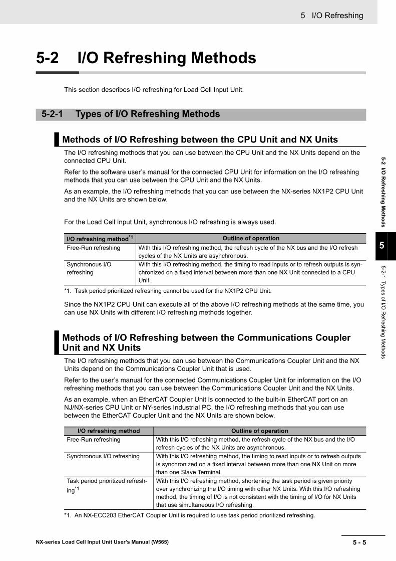
5 - 5
5 I/O Refreshing
NX-series Load Cell Input Unit User’s Manual (W565)
5-2 I/O R
efresh
ing
Meth
od
s
5
5-2-1 Types of I/O
Refreshing M
ethods
5-2 I/O Refreshing Methods
This section describes I/O refreshing for Load Cell Input Unit.
The I/O refreshing methods that you can use between the CPU Unit and the NX Units depend on the connected CPU Unit.
Refer to the software user’s manual for the connected CPU Unit for information on the I/O refreshing methods that you can use between the CPU Unit and the NX Units.
As an example, the I/O refreshing methods that you can use between the NX-series NX1P2 CPU Unit and the NX Units are shown below.
For the Load Cell Input Unit, synchronous I/O refreshing is always used.
Since the NX1P2 CPU Unit can execute all of the above I/O refreshing methods at the same time, you can use NX Units with different I/O refreshing methods together.
The I/O refreshing methods that you can use between the Communications Coupler Unit and the NX Units depend on the Communications Coupler Unit that is used.
Refer to the user’s manual for the connected Communications Coupler Unit for information on the I/O refreshing methods that you can use between the Communications Coupler Unit and the NX Units.
As an example, when an EtherCAT Coupler Unit is connected to the built-in EtherCAT port on an NJ/NX-series CPU Unit or NY-series Industrial PC, the I/O refreshing methods that you can use between the EtherCAT Coupler Unit and the NX Units are shown below.
5-2-1 Types of I/O Refreshing Methods
Methods of I/O Refreshing between the CPU Unit and NX Units
I/O refreshing method*1
*1. Task period prioritized refreshing cannot be used for the NX1P2 CPU Unit.
Outline of operation
Free-Run refreshing With this I/O refreshing method, the refresh cycle of the NX bus and the I/O refresh cycles of the NX Units are asynchronous.
Synchronous I/O refreshing
With this I/O refreshing method, the timing to read inputs or to refresh outputs is syn-chronized on a fixed interval between more than one NX Unit connected to a CPU Unit.
Methods of I/O Refreshing between the Communications Coupler Unit and NX Units
I/O refreshing method Outline of operation
Free-Run refreshing With this I/O refreshing method, the refresh cycle of the NX bus and the I/O refresh cycles of the NX Units are asynchronous.
Synchronous I/O refreshing With this I/O refreshing method, the timing to read inputs or to refresh outputs is synchronized on a fixed interval between more than one NX Unit on more than one Slave Terminal.
Task period prioritized refresh-
ing*1
*1. An NX-ECC203 EtherCAT Coupler Unit is required to use task period prioritized refreshing.
With this I/O refreshing method, shortening the task period is given priority over synchronizing the I/O timing with other NX Units. With this I/O refreshing method, the timing of I/O is not consistent with the timing of I/O for NX Units that use simultaneous I/O refreshing.
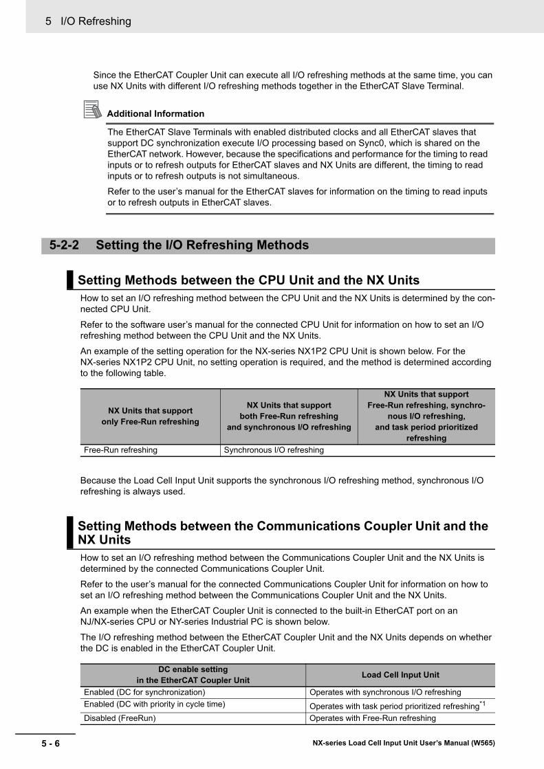
5 I/O Refreshing
5 - 6 NX-series Load Cell Input Unit User’s Manual (W565)
Since the EtherCAT Coupler Unit can execute all I/O refreshing methods at the same time, you can use NX Units with different I/O refreshing methods together in the EtherCAT Slave Terminal.
Additional Information
The EtherCAT Slave Terminals with enabled distributed clocks and all EtherCAT slaves that support DC synchronization execute I/O processing based on Sync0, which is shared on the EtherCAT network. However, because the specifications and performance for the timing to read inputs or to refresh outputs for EtherCAT slaves and NX Units are different, the timing to read inputs or to refresh outputs is not simultaneous.
Refer to the user’s manual for the EtherCAT slaves for information on the timing to read inputs or to refresh outputs in EtherCAT slaves.
How to set an I/O refreshing method between the CPU Unit and the NX Units is determined by the con-nected CPU Unit.
Refer to the software user’s manual for the connected CPU Unit for information on how to set an I/O refreshing method between the CPU Unit and the NX Units.
An example of the setting operation for the NX-series NX1P2 CPU Unit is shown below. For the NX-series NX1P2 CPU Unit, no setting operation is required, and the method is determined according to the following table.
Because the Load Cell Input Unit supports the synchronous I/O refreshing method, synchronous I/O refreshing is always used.
How to set an I/O refreshing method between the Communications Coupler Unit and the NX Units is determined by the connected Communications Coupler Unit.
Refer to the user’s manual for the connected Communications Coupler Unit for information on how to set an I/O refreshing method between the Communications Coupler Unit and the NX Units.
An example when the EtherCAT Coupler Unit is connected to the built-in EtherCAT port on an NJ/NX-series CPU or NY-series Industrial PC is shown below.
The I/O refreshing method between the EtherCAT Coupler Unit and the NX Units depends on whether the DC is enabled in the EtherCAT Coupler Unit.
5-2-2 Setting the I/O Refreshing Methods
Setting Methods between the CPU Unit and the NX Units
NX Units that support only Free-Run refreshing
NX Units that support both Free-Run refreshing
and synchronous I/O refreshing
NX Units that support Free-Run refreshing, synchro-
nous I/O refreshing, and task period prioritized
refreshing
Free-Run refreshing Synchronous I/O refreshing
Setting Methods between the Communications Coupler Unit and the NX Units
DC enable setting in the EtherCAT Coupler Unit
Load Cell Input Unit
Enabled (DC for synchronization) Operates with synchronous I/O refreshing
Enabled (DC with priority in cycle time) Operates with task period prioritized refreshing*1
Disabled (FreeRun) Operates with Free-Run refreshing
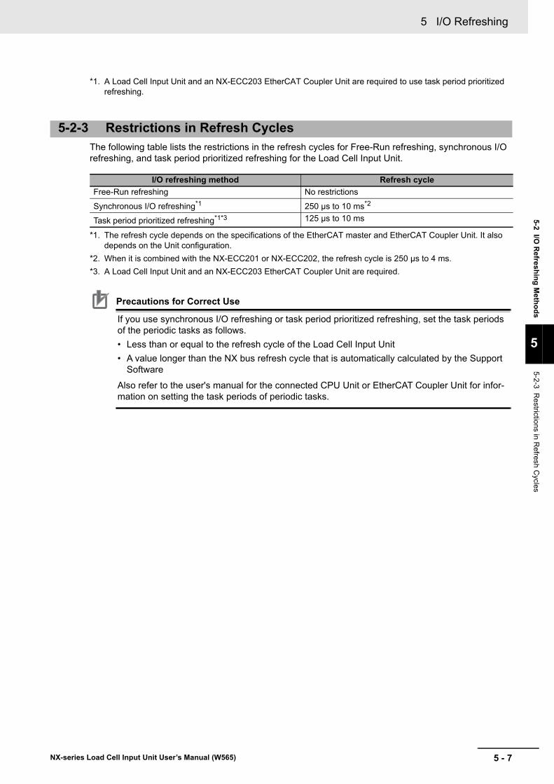
5 - 7
5 I/O Refreshing
NX-series Load Cell Input Unit User’s Manual (W565)
5-2 I/O R
efresh
ing
Meth
od
s
5
5-2-3 Restrictions in R
efresh Cycles
The following table lists the restrictions in the refresh cycles for Free-Run refreshing, synchronous I/O refreshing, and task period prioritized refreshing for the Load Cell Input Unit.
Precautions for Correct Use
If you use synchronous I/O refreshing or task period prioritized refreshing, set the task periods of the periodic tasks as follows.
• Less than or equal to the refresh cycle of the Load Cell Input Unit
• A value longer than the NX bus refresh cycle that is automatically calculated by the Support Software
Also refer to the user's manual for the connected CPU Unit or EtherCAT Coupler Unit for infor-mation on setting the task periods of periodic tasks.
*1. A Load Cell Input Unit and an NX-ECC203 EtherCAT Coupler Unit are required to use task period prioritized refreshing.
5-2-3 Restrictions in Refresh Cycles
I/O refreshing method Refresh cycle
Free-Run refreshing No restrictions
Synchronous I/O refreshing*1
*1. The refresh cycle depends on the specifications of the EtherCAT master and EtherCAT Coupler Unit. It also depends on the Unit configuration.
250 μs to 10 ms*2
*2. When it is combined with the NX-ECC201 or NX-ECC202, the refresh cycle is 250 μs to 4 ms.
Task period prioritized refreshing*1*3
*3. A Load Cell Input Unit and an NX-ECC203 EtherCAT Coupler Unit are required.
125 μs to 10 ms
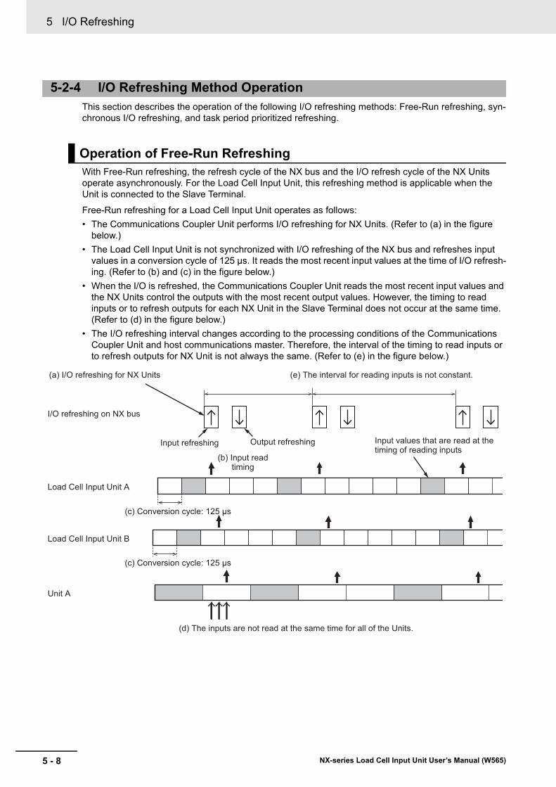
5 I/O Refreshing
5 - 8 NX-series Load Cell Input Unit User’s Manual (W565)
This section describes the operation of the following I/O refreshing methods: Free-Run refreshing, syn-chronous I/O refreshing, and task period prioritized refreshing.
With Free-Run refreshing, the refresh cycle of the NX bus and the I/O refresh cycle of the NX Units operate asynchronously. For the Load Cell Input Unit, this refreshing method is applicable when the Unit is connected to the Slave Terminal.
Free-Run refreshing for a Load Cell Input Unit operates as follows:
• The Communications Coupler Unit performs I/O refreshing for NX Units. (Refer to (a) in the figure below.)
• The Load Cell Input Unit is not synchronized with I/O refreshing of the NX bus and refreshes input values in a conversion cycle of 125 μs. It reads the most recent input values at the time of I/O refresh-ing. (Refer to (b) and (c) in the figure below.)
• When the I/O is refreshed, the Communications Coupler Unit reads the most recent input values and the NX Units control the outputs with the most recent output values. However, the timing to read inputs or to refresh outputs for each NX Unit in the Slave Terminal does not occur at the same time. (Refer to (d) in the figure below.)
• The I/O refreshing interval changes according to the processing conditions of the Communications Coupler Unit and host communications master. Therefore, the interval of the timing to read inputs or to refresh outputs for NX Unit is not always the same. (Refer to (e) in the figure below.)
5-2-4 I/O Refreshing Method Operation
Operation of Free-Run Refreshing
I/O refreshing on NX bus
Unit A
Load Cell Input Unit A
Input refreshing Output refreshing
(a) I/O refreshing for NX Units (e) The interval for reading inputs is not constant.
Load Cell Input Unit B
(c) Conversion cycle: 125 μs
(c) Conversion cycle: 125 μs
(d) The inputs are not read at the same time for all of the Units.
Input values that are read at the timing of reading inputs
(b) Input read timing
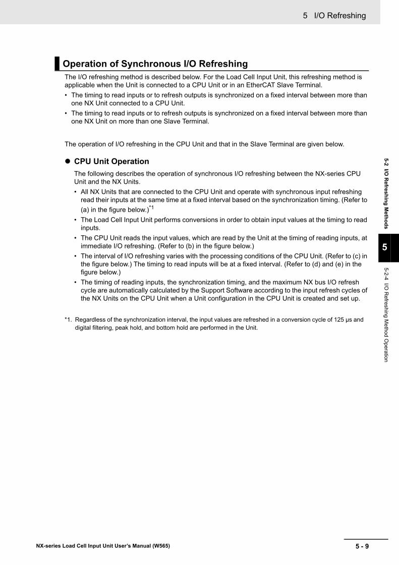
5 - 9
5 I/O Refreshing
NX-series Load Cell Input Unit User’s Manual (W565)
5-2 I/O R
efresh
ing
Meth
od
s
5
5-2-4 I/O R
efreshing Method O
peration
The I/O refreshing method is described below. For the Load Cell Input Unit, this refreshing method is applicable when the Unit is connected to a CPU Unit or in an EtherCAT Slave Terminal.
• The timing to read inputs or to refresh outputs is synchronized on a fixed interval between more than one NX Unit connected to a CPU Unit.
• The timing to read inputs or to refresh outputs is synchronized on a fixed interval between more than one NX Unit on more than one Slave Terminal.
The operation of I/O refreshing in the CPU Unit and that in the Slave Terminal are given below.
CPU Unit Operation
The following describes the operation of synchronous I/O refreshing between the NX-series CPU Unit and the NX Units.
• All NX Units that are connected to the CPU Unit and operate with synchronous input refreshing read their inputs at the same time at a fixed interval based on the synchronization timing. (Refer to
(a) in the figure below.)*1
• The Load Cell Input Unit performs conversions in order to obtain input values at the timing to read inputs.
• The CPU Unit reads the input values, which are read by the Unit at the timing of reading inputs, at immediate I/O refreshing. (Refer to (b) in the figure below.)
• The interval of I/O refreshing varies with the processing conditions of the CPU Unit. (Refer to (c) in the figure below.) The timing to read inputs will be at a fixed interval. (Refer to (d) and (e) in the figure below.)
• The timing of reading inputs, the synchronization timing, and the maximum NX bus I/O refresh cycle are automatically calculated by the Support Software according to the input refresh cycles of the NX Units on the CPU Unit when a Unit configuration in the CPU Unit is created and set up.
*1. Regardless of the synchronization interval, the input values are refreshed in a conversion cycle of 125 μs and digital filtering, peak hold, and bottom hold are performed in the Unit.
Operation of Synchronous I/O Refreshing
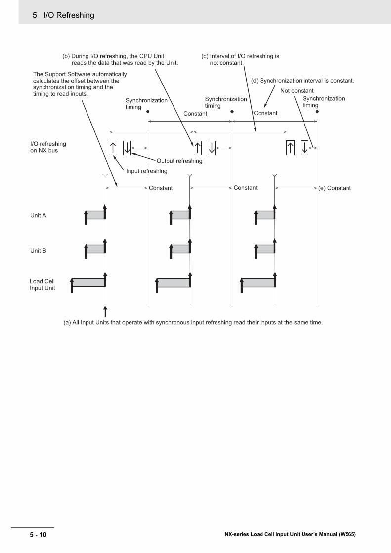
5 I/O Refreshing
5 - 10 NX-series Load Cell Input Unit User’s Manual (W565)
Input refreshing
Output refreshing
(b) During I/O refreshing, the CPU Unit reads the data that was read by the Unit.
(c) Interval of I/O refreshing is not constant.
I/O refreshingon NX bus
Synchronizationtiming
Unit A
Unit B
Load CellInput Unit
The Support Software automatically calculates the offset between the synchronization timing and the timing to read inputs.
Constant Constant (e) Constant
Not constant
Constant Constant
Synchronizationtiming
(d) Synchronization interval is constant.
(a) All Input Units that operate with synchronous input refreshing read their inputs at the same time.
Synchronizationtiming
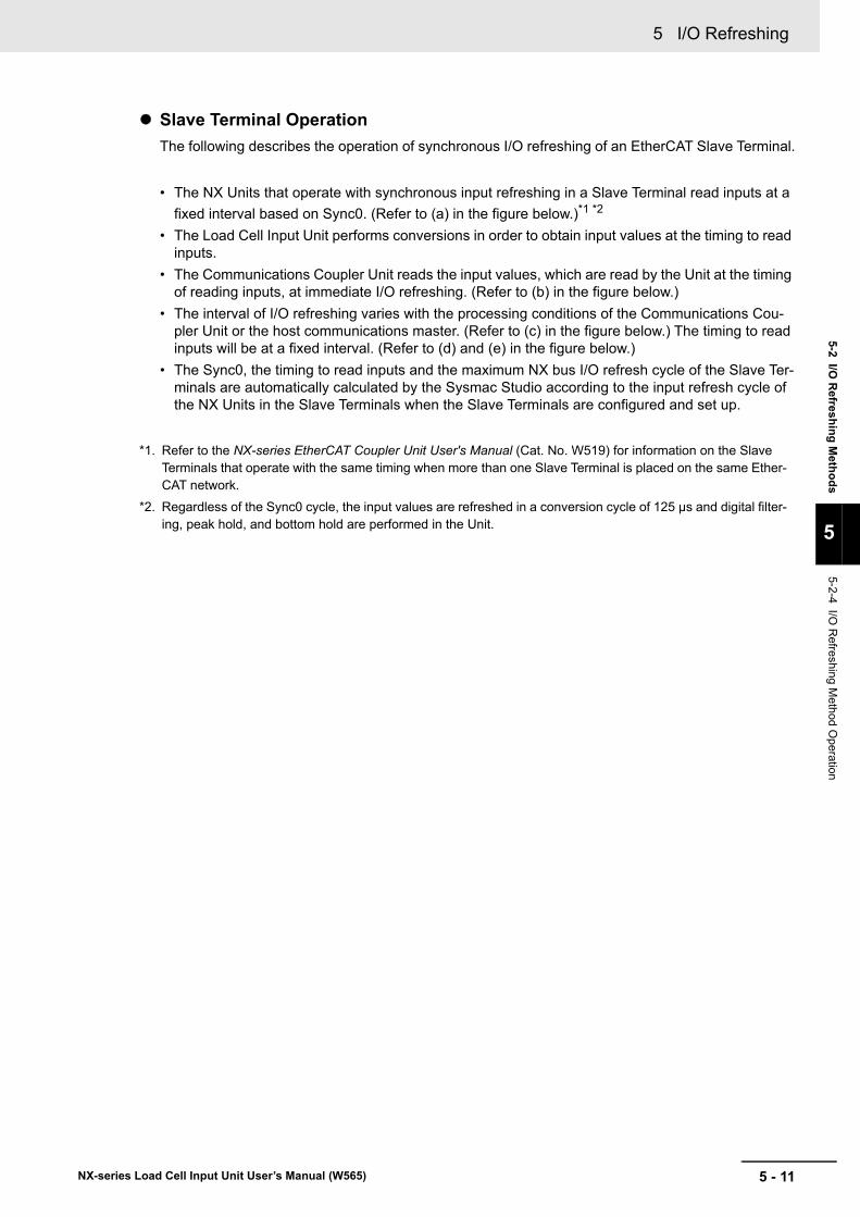
5 - 11
5 I/O Refreshing
NX-series Load Cell Input Unit User’s Manual (W565)
5-2 I/O R
efresh
ing
Meth
od
s
5
5-2-4 I/O R
efreshing Method O
peration
Slave Terminal Operation
The following describes the operation of synchronous I/O refreshing of an EtherCAT Slave Terminal.
• The NX Units that operate with synchronous input refreshing in a Slave Terminal read inputs at a
fixed interval based on Sync0. (Refer to (a) in the figure below.)*1 *2
• The Load Cell Input Unit performs conversions in order to obtain input values at the timing to read inputs.
• The Communications Coupler Unit reads the input values, which are read by the Unit at the timing of reading inputs, at immediate I/O refreshing. (Refer to (b) in the figure below.)
• The interval of I/O refreshing varies with the processing conditions of the Communications Cou-pler Unit or the host communications master. (Refer to (c) in the figure below.) The timing to read inputs will be at a fixed interval. (Refer to (d) and (e) in the figure below.)
• The Sync0, the timing to read inputs and the maximum NX bus I/O refresh cycle of the Slave Ter-minals are automatically calculated by the Sysmac Studio according to the input refresh cycle of the NX Units in the Slave Terminals when the Slave Terminals are configured and set up.
*1. Refer to the NX-series EtherCAT Coupler Unit User's Manual (Cat. No. W519) for information on the Slave Terminals that operate with the same timing when more than one Slave Terminal is placed on the same Ether-CAT network.
*2. Regardless of the Sync0 cycle, the input values are refreshed in a conversion cycle of 125 μs and digital filter-ing, peak hold, and bottom hold are performed in the Unit.
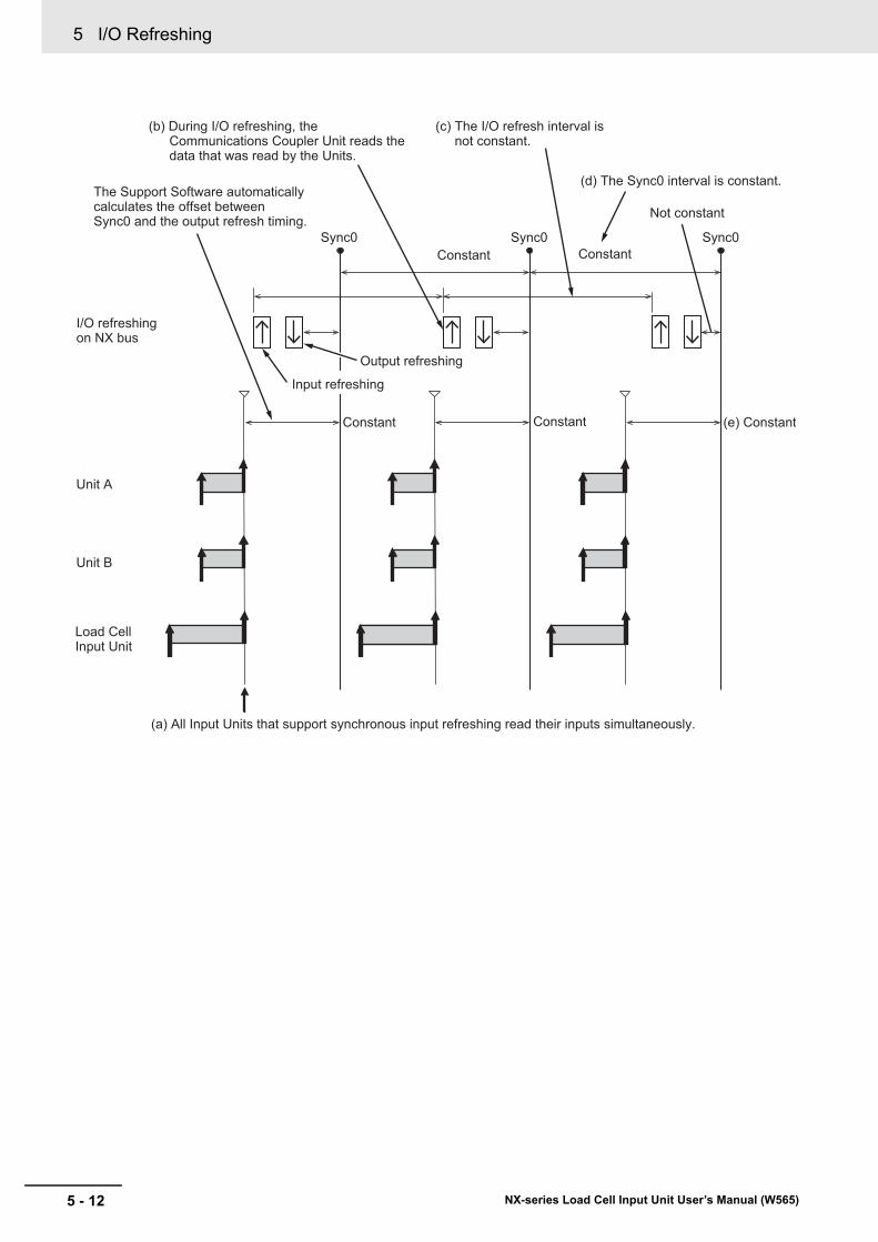
5 I/O Refreshing
5 - 12 NX-series Load Cell Input Unit User’s Manual (W565)
Input refreshing
Output refreshing
(b) During I/O refreshing, the Communications Coupler Unit reads the data that was read by the Units.
(c) The I/O refresh interval is not constant.
I/O refreshing on NX bus
Sync0
Unit A
Unit B
Load Cell Input Unit
The Support Software automatically calculates the offset between Sync0 and the output refresh timing.
Constant Constant (e) Constant
Not constant
ConstantConstantSync0
(d) The Sync0 interval is constant.
(a) All Input Units that support synchronous input refreshing read their inputs simultaneously.
Sync0
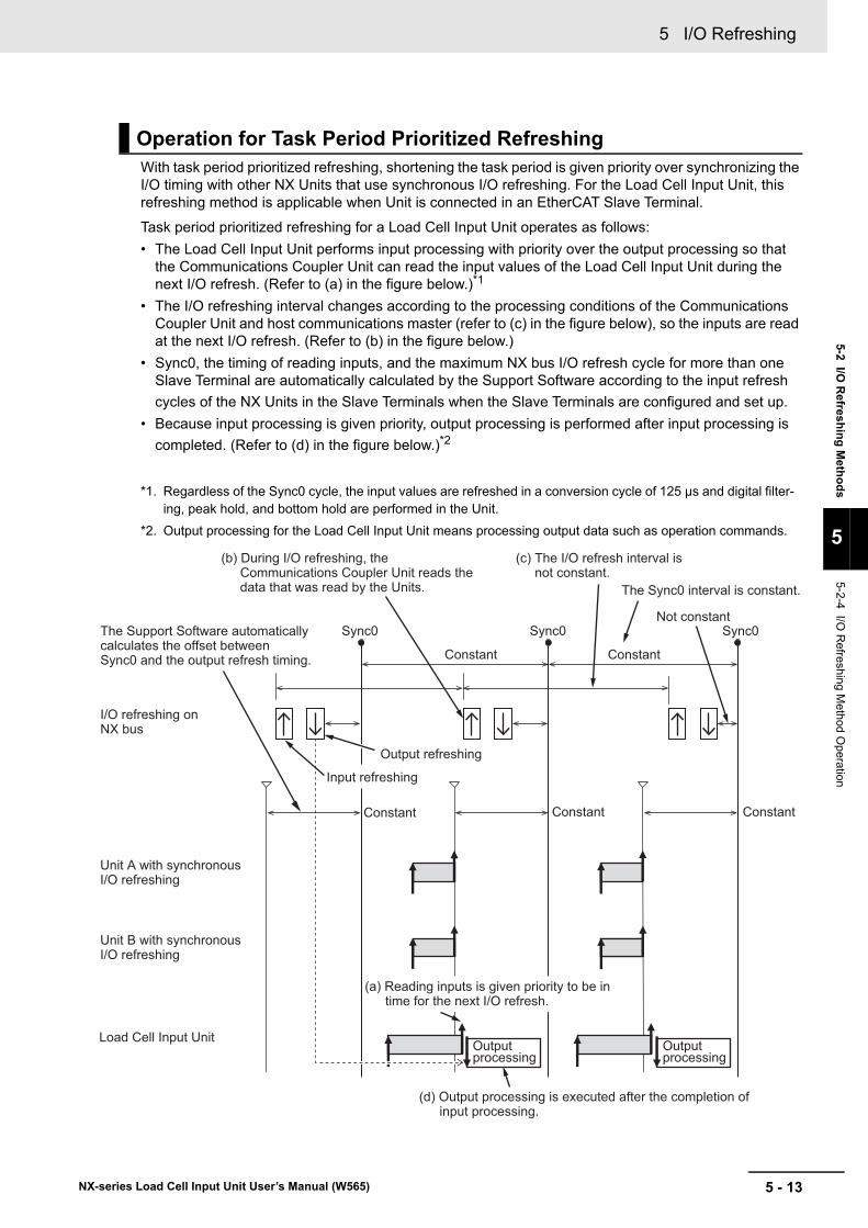
5 - 13
5 I/O Refreshing
NX-series Load Cell Input Unit User’s Manual (W565)
5-2 I/O R
efresh
ing
Meth
od
s
5
5-2-4 I/O R
efreshing Method O
peration
With task period prioritized refreshing, shortening the task period is given priority over synchronizing the I/O timing with other NX Units that use synchronous I/O refreshing. For the Load Cell Input Unit, this refreshing method is applicable when Unit is connected in an EtherCAT Slave Terminal.
Task period prioritized refreshing for a Load Cell Input Unit operates as follows:
• The Load Cell Input Unit performs input processing with priority over the output processing so that the Communications Coupler Unit can read the input values of the Load Cell Input Unit during the next I/O refresh. (Refer to (a) in the figure below.)*1
• The I/O refreshing interval changes according to the processing conditions of the Communications Coupler Unit and host communications master (refer to (c) in the figure below), so the inputs are read at the next I/O refresh. (Refer to (b) in the figure below.)
• Sync0, the timing of reading inputs, and the maximum NX bus I/O refresh cycle for more than one Slave Terminal are automatically calculated by the Support Software according to the input refresh
cycles of the NX Units in the Slave Terminals when the Slave Terminals are configured and set up.
• Because input processing is given priority, output processing is performed after input processing is
completed. (Refer to (d) in the figure below.)*2
*1. Regardless of the Sync0 cycle, the input values are refreshed in a conversion cycle of 125 μs and digital filter-ing, peak hold, and bottom hold are performed in the Unit.
*2. Output processing for the Load Cell Input Unit means processing output data such as operation commands.
Operation for Task Period Prioritized Refreshing
I/O refreshing on NX bus
Sync0 Sync0
Unit A with synchronous I/O refreshing
Unit B with synchronous I/O refreshing
Load Cell Input Unit
The Support Software automatically calculates the offset between Sync0 and the output refresh timing.
Constant Constant Constant
ConstantConstant
Sync0
(b) During I/O refreshing, the Communications Coupler Unit reads the data that was read by the Units.
(c) The I/O refresh interval is not constant.
The Sync0 interval is constant.
Input refreshing
Output refreshing
Not constant
(a) Reading inputs is given priority to be in time for the next I/O refresh.
(d) Output processing is executed after the completion of input processing.
Output processing
Output processing

5 I/O Refreshing
5 - 14 NX-series Load Cell Input Unit User’s Manual (W565)
6 - 1
6
NX-series Load Cell Input Unit User’s Manual (W565)
This section describes the specifications of input conversion and I/O data for the Load Cell Input Unit.
6-1 Specifications of Input Conversion . . . . . . . . . . . . . . . . . . . . . . . . . . . . . . . 6-26-1-1 General Properties of the Load Cell . . . . . . . . . . . . . . . . . . . . . . . . . . . . . . . . . 6-2
6-1-2 Terms Used in Weight Measurement . . . . . . . . . . . . . . . . . . . . . . . . . . . . . . . . 6-4
6-1-3 Detailed Specifications of Input Conversion . . . . . . . . . . . . . . . . . . . . . . . . . . . 6-5
6-2 Specifications of I/O Data . . . . . . . . . . . . . . . . . . . . . . . . . . . . . . . . . . . . . . 6-136-2-1 Data Items for Allocation to I/O . . . . . . . . . . . . . . . . . . . . . . . . . . . . . . . . . . . . 6-13
6-2-2 Data Details . . . . . . . . . . . . . . . . . . . . . . . . . . . . . . . . . . . . . . . . . . . . . . . . . . 6-15
Specifications of Input Conver-sion and I/O Data
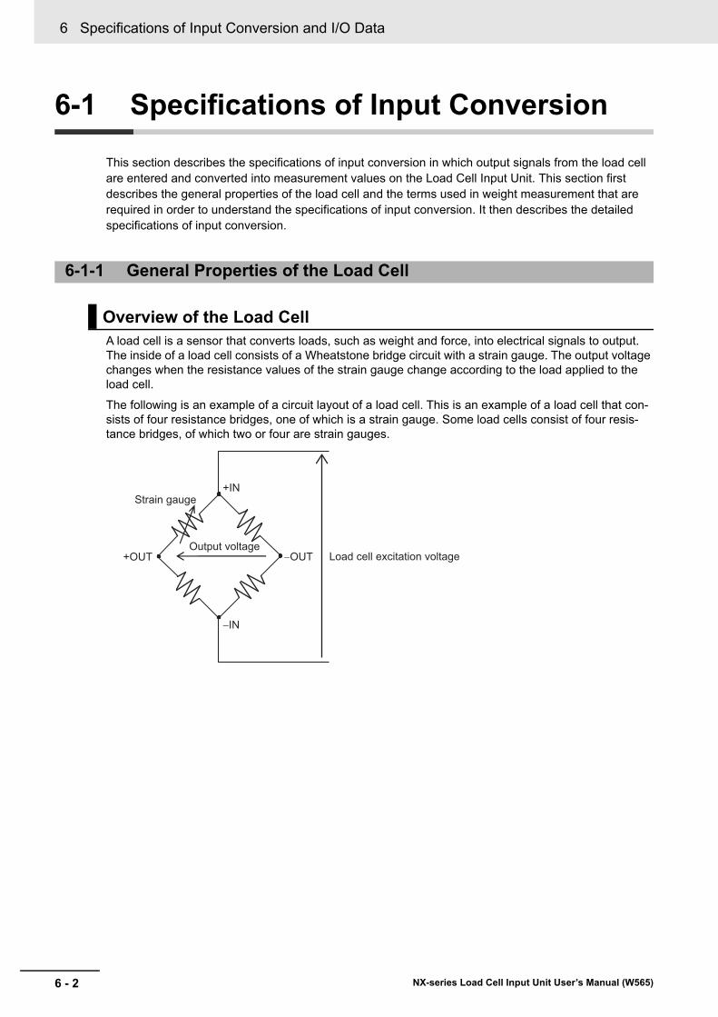
6 Specifications of Input Conversion and I/O Data
6 - 2 NX-series Load Cell Input Unit User’s Manual (W565)
6-1 Specifications of Input Conversion
This section describes the specifications of input conversion in which output signals from the load cell are entered and converted into measurement values on the Load Cell Input Unit. This section first describes the general properties of the load cell and the terms used in weight measurement that are required in order to understand the specifications of input conversion. It then describes the detailed specifications of input conversion.
A load cell is a sensor that converts loads, such as weight and force, into electrical signals to output. The inside of a load cell consists of a Wheatstone bridge circuit with a strain gauge. The output voltage changes when the resistance values of the strain gauge change according to the load applied to the load cell.
The following is an example of a circuit layout of a load cell. This is an example of a load cell that con-sists of four resistance bridges, one of which is a strain gauge. Some load cells consist of four resis-tance bridges, of which two or four are strain gauges.
6-1-1 General Properties of the Load Cell
Overview of the Load Cell
+IN
−IN
−OUT +OUT Load cell excitation voltageOutput voltage
Strain gauge
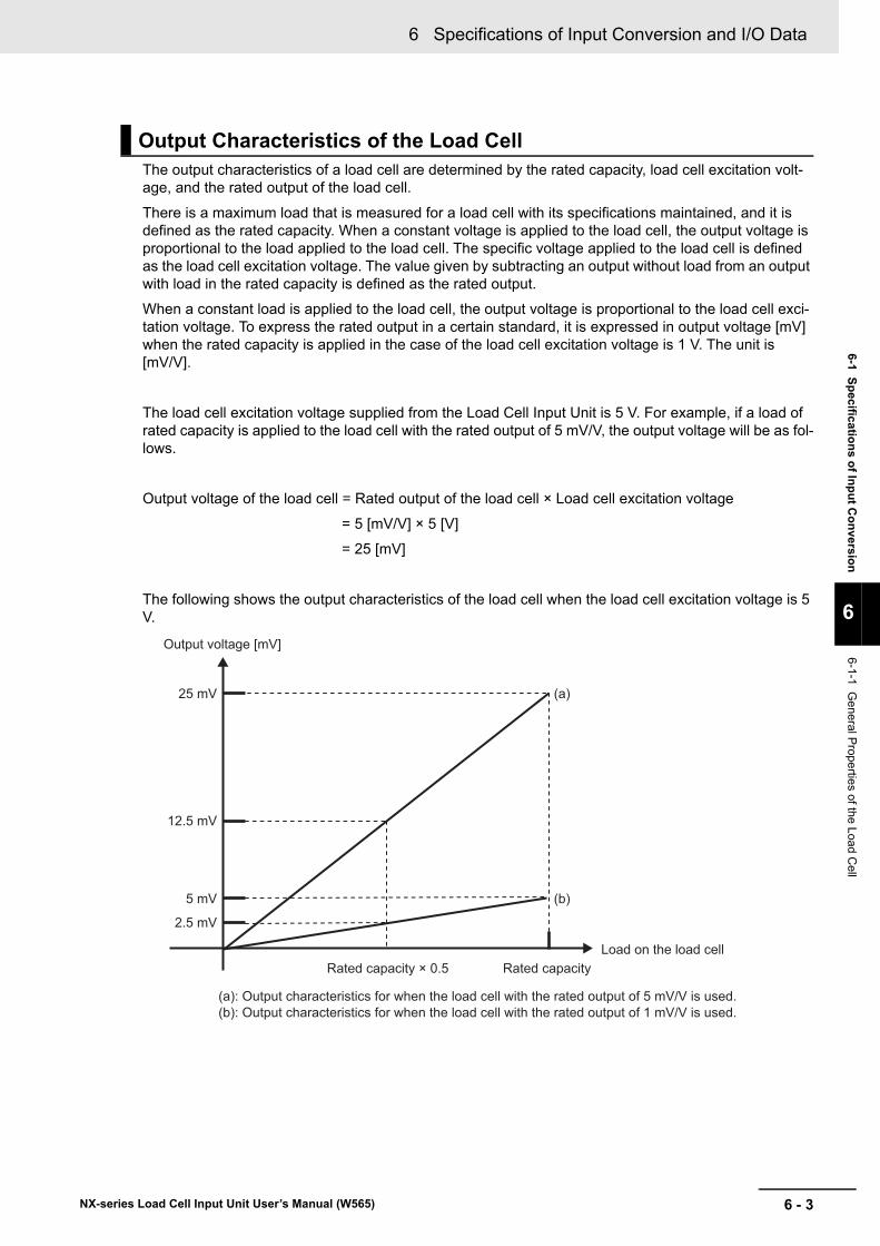
6 - 3
6 Specifications of Input Conversion and I/O Data
NX-series Load Cell Input Unit User’s Manual (W565)
6-1 Sp
ecificatio
ns o
f Inp
ut C
on
version
6
6-1-1 General P
roperties of the Load Cell
The output characteristics of a load cell are determined by the rated capacity, load cell excitation volt-age, and the rated output of the load cell.
There is a maximum load that is measured for a load cell with its specifications maintained, and it is defined as the rated capacity. When a constant voltage is applied to the load cell, the output voltage is proportional to the load applied to the load cell. The specific voltage applied to the load cell is defined as the load cell excitation voltage. The value given by subtracting an output without load from an output with load in the rated capacity is defined as the rated output.
When a constant load is applied to the load cell, the output voltage is proportional to the load cell exci-tation voltage. To express the rated output in a certain standard, it is expressed in output voltage [mV] when the rated capacity is applied in the case of the load cell excitation voltage is 1 V. The unit is [mV/V].
The load cell excitation voltage supplied from the Load Cell Input Unit is 5 V. For example, if a load of rated capacity is applied to the load cell with the rated output of 5 mV/V, the output voltage will be as fol-lows.
Output voltage of the load cell = Rated output of the load cell × Load cell excitation voltage
= 5 [mV/V] × 5 [V]
= 25 [mV]
The following shows the output characteristics of the load cell when the load cell excitation voltage is 5 V.
Output Characteristics of the Load Cell
Load on the load cell
25 mV
Rated capacity Rated capacity × 0.5
Output voltage [mV]
12.5 mV
2.5 mV
5 mV
(a)
(a): Output characteristics for when the load cell with the rated output of 5 mV/V is used.(b): Output characteristics for when the load cell with the rated output of 1 mV/V is used.
(b)
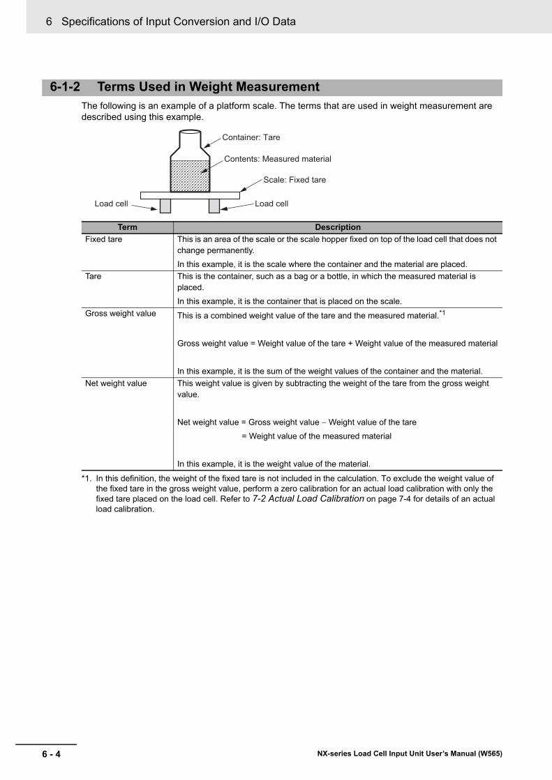
6 Specifications of Input Conversion and I/O Data
6 - 4 NX-series Load Cell Input Unit User’s Manual (W565)
The following is an example of a platform scale. The terms that are used in weight measurement are described using this example.
6-1-2 Terms Used in Weight Measurement
Term Description
Fixed tare This is an area of the scale or the scale hopper fixed on top of the load cell that does not change permanently.
In this example, it is the scale where the container and the material are placed.
Tare This is the container, such as a bag or a bottle, in which the measured material is placed.
In this example, it is the container that is placed on the scale.
Gross weight value This is a combined weight value of the tare and the measured material.*1
Gross weight value = Weight value of the tare + Weight value of the measured material
In this example, it is the sum of the weight values of the container and the material.
*1. In this definition, the weight of the fixed tare is not included in the calculation. To exclude the weight value of the fixed tare in the gross weight value, perform a zero calibration for an actual load calibration with only the fixed tare placed on the load cell. Refer to 7-2 Actual Load Calibration on page 7-4 for details of an actual load calibration.
Net weight value This weight value is given by subtracting the weight of the tare from the gross weight value.
Net weight value = Gross weight value Weight value of the tare
= Weight value of the measured material
In this example, it is the weight value of the material.
Scale: Fixed tare
Load cellLoad cell
Container: Tare
Contents: Measured material
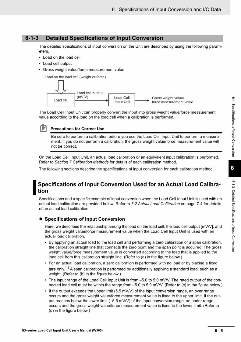
6 - 5
6 Specifications of Input Conversion and I/O Data
NX-series Load Cell Input Unit User’s Manual (W565)
6-1 Sp
ecificatio
ns o
f Inp
ut C
on
version
6
6-1-3 De
tailed Specification
s of Input C
onversion
The detailed specifications of input conversion on the Unit are described by using the following param-eters.
• Load on the load cell
• Load cell output
• Gross weight value/force measurement value
The Load Cell Input Unit can properly convert the input into gross weight value/force measurement value according to the load on the load cell when a calibration is performed.
Precautions for Correct Use
Be sure to perform a calibration before you use the Load Cell Input Unit to perform a measure-ment. If you do not perform a calibration, the gross weight value/force measurement value will not be correct.
On the Load Cell Input Unit, an actual load calibration or an equivalent input calibration is performed. Refer to Section 7 Calibration Methods for details of each calibration method.
The following sections describe the specifications of input conversion for each calibration method.
Specifications and a specific example of input conversion when the Load Cell Input Unit is used with an actual load calibration are provided below. Refer to 7-2 Actual Load Calibration on page 7-4 for details of an actual load calibration.
Specifications of Input Conversion
Here, we describes the relationship among the load on the load cell, the load cell output [mV/V], and the gross weight value/force measurement value when the Load Cell Input Unit is used with an actual load calibration.
• By applying an actual load to the load cell and performing a zero calibration or a span calibration, the calibration straight line that connects the zero point and the span point is acquired. The gross weight value/force measurement value is converted according to the load that is applied to the load cell from this calibration straight line. (Refer to (a) in the figure below.)
• For an actual load calibration, a zero calibration is performed with no load or by placing a fixed
tare only.* 1 A span calibration is performed by additionally applying a standard load, such as a weight. (Refer to (b) in the figure below.)
• The input range of the Load Cell Input Unit is from 5.0 to 5.0 mV/V. The rated output of the con-nected load cell must be within the range from 5.0 to 5.0 mV/V. (Refer to (c) in the figure below.)
• If the output exceeds the upper limit (5.5 mV/V) of the input conversion range, an over range occurs and the gross weight value/force measurement value is fixed to the upper limit. If the out-put reaches below the lower limit (5.5 mV/V) of the input conversion range, an under range occurs and the gross weight value/force measurement value is fixed to the lower limit. (Refer to (d) in the figure below.)
6-1-3 Detailed Specifications of Input Conversion
Specifications of Input Conversion Used for an Actual Load Calibra-tion
Gross weight value/force measurement value
Load cell output(mV/V) Load Cell
Input Unit
Load on the load cell (weight or force)
Load cell
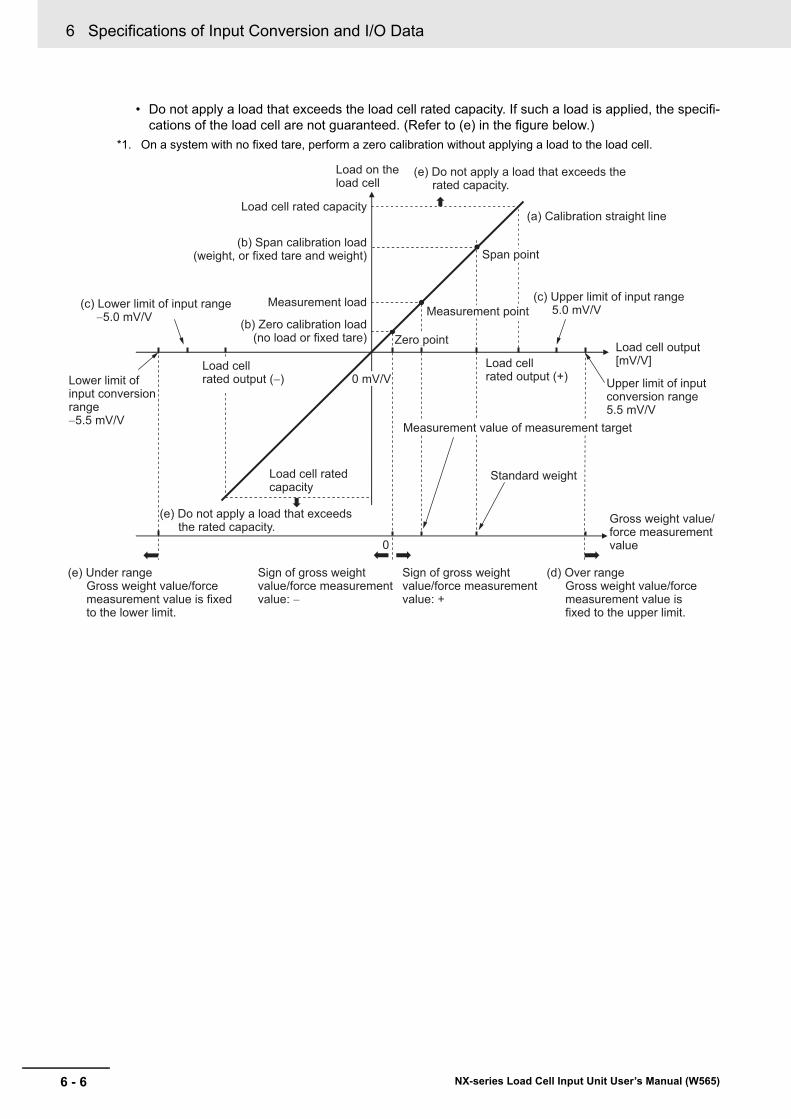
6 Specifications of Input Conversion and I/O Data
6 - 6 NX-series Load Cell Input Unit User’s Manual (W565)
• Do not apply a load that exceeds the load cell rated capacity. If such a load is applied, the specifi-cations of the load cell are not guaranteed. (Refer to (e) in the figure below.)
*1. On a system with no fixed tare, perform a zero calibration without applying a load to the load cell.
Load cell rated output (+)
Load cell rated output (−)
Load on the load cell
Standard weight
Measurement value of measurement target
Load cell rated capacity
(b) Span calibration load(weight, or fixed tare and weight)
0
Load cell rated capacity
Span point
Measurement point
Zero point(b) Zero calibration load
(no load or fixed tare)
Measurement load
Load cell output[mV/V]
Gross weight value/force measurement value
(a) Calibration straight line
Sign of gross weight value/force measurement value: −
Sign of gross weight value/force measurement value: +
(c) Lower limit of input range −5.0 mV/V
(c) Upper limit of input range5.0 mV/V
Upper limit of input conversion range5.5 mV/V
(e) Under range Gross weight value/force measurement value is fixed to the lower limit.
(d) Over range Gross weight value/force measurement value is fixed to the upper limit.
Lower limit of input conversion range−5.5 mV/V
(e) Do not apply a load that exceeds the rated capacity.
(e) Do not apply a load that exceeds the rated capacity.
0 mV/V
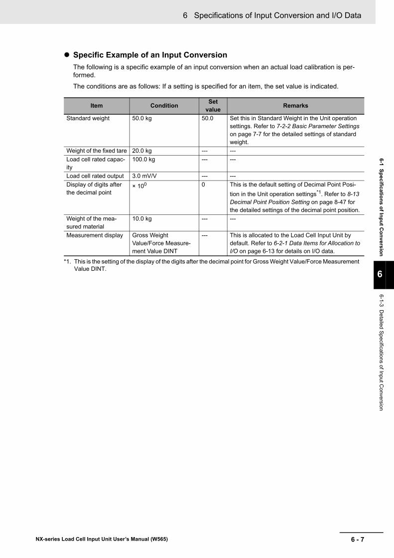
6 - 7
6 Specifications of Input Conversion and I/O Data
NX-series Load Cell Input Unit User’s Manual (W565)
6-1 Sp
ecificatio
ns o
f Inp
ut C
on
version
6
6-1-3 De
tailed Specification
s of Input C
onversion
Specific Example of an Input Conversion
The following is a specific example of an input conversion when an actual load calibration is per-formed.
The conditions are as follows: If a setting is specified for an item, the set value is indicated.
Item ConditionSet
valueRemarks
Standard weight 50.0 kg 50.0 Set this in Standard Weight in the Unit operation settings. Refer to 7-2-2 Basic Parameter Settings on page 7-7 for the detailed settings of standard weight.
Weight of the fixed tare 20.0 kg --- ---
Load cell rated capac-ity
100.0 kg --- ---
Load cell rated output 3.0 mV/V --- ---
Display of digits after the decimal point
× 100 0 This is the default setting of Decimal Point Posi-
tion in the Unit operation settings*1. Refer to 8-13 Decimal Point Position Setting on page 8-47 for the detailed settings of the decimal point position.
*1. This is the setting of the display of the digits after the decimal point for Gross Weight Value/Force Measurement Value DINT.
Weight of the mea-sured material
10.0 kg --- ---
Measurement display Gross Weight Value/Force Measure-ment Value DINT
--- This is allocated to the Load Cell Input Unit by default. Refer to 6-2-1 Data Items for Allocation to I/O on page 6-13 for details on I/O data.
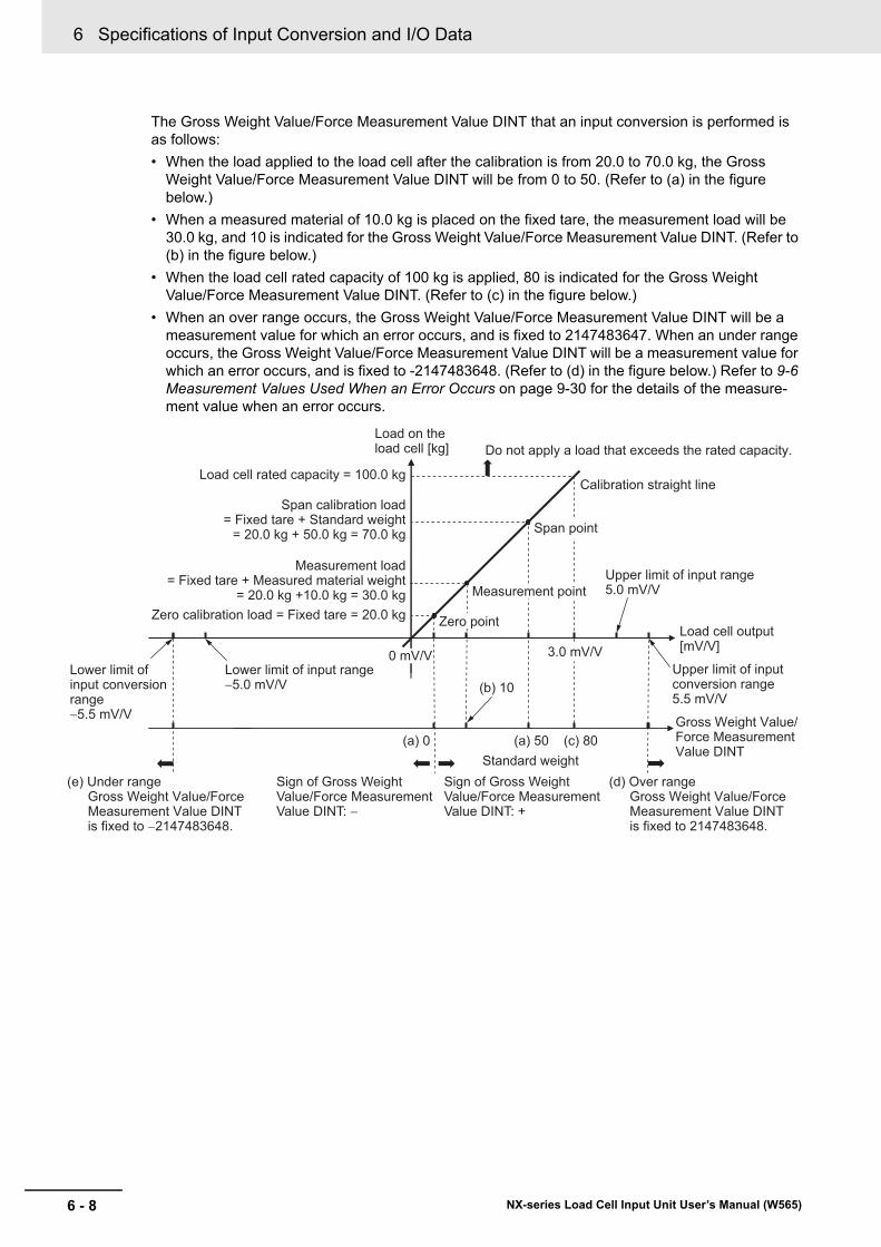
6 Specifications of Input Conversion and I/O Data
6 - 8 NX-series Load Cell Input Unit User’s Manual (W565)
The Gross Weight Value/Force Measurement Value DINT that an input conversion is performed is as follows:
• When the load applied to the load cell after the calibration is from 20.0 to 70.0 kg, the Gross Weight Value/Force Measurement Value DINT will be from 0 to 50. (Refer to (a) in the figure below.)
• When a measured material of 10.0 kg is placed on the fixed tare, the measurement load will be 30.0 kg, and 10 is indicated for the Gross Weight Value/Force Measurement Value DINT. (Refer to (b) in the figure below.)
• When the load cell rated capacity of 100 kg is applied, 80 is indicated for the Gross Weight Value/Force Measurement Value DINT. (Refer to (c) in the figure below.)
• When an over range occurs, the Gross Weight Value/Force Measurement Value DINT will be a measurement value for which an error occurs, and is fixed to 2147483647. When an under range occurs, the Gross Weight Value/Force Measurement Value DINT will be a measurement value for which an error occurs, and is fixed to -2147483648. (Refer to (d) in the figure below.) Refer to 9-6 Measurement Values Used When an Error Occurs on page 9-30 for the details of the measure-ment value when an error occurs.
Standard weight
Load cell rated capacity = 100.0 kg
Span calibration load = Fixed tare + Standard weight
= 20.0 kg + 50.0 kg = 70.0 kg
(a) 0
Do not apply a load that exceeds the rated capacity.
Span point
Measurement point
Zero pointZero calibration load = Fixed tare = 20.0 kg
Measurement load = Fixed tare + Measured material weight
= 20.0 kg +10.0 kg = 30.0 kg
Lower limit of input conversion range−5.5 mV/V
Upper limit of input conversion range5.5 mV/V
3.0 mV/V Lower limit of input range−5.0 mV/V
Upper limit of input range5.0 mV/V
Gross Weight Value/Force MeasurementValue DINT
Calibration straight line
Load on the load cell [kg]
(e) Under range Gross Weight Value/ForceMeasurement Value DINT is fixed to −2147483648.
(d) Over range Gross Weight Value/ForceMeasurement Value DINT is fixed to 2147483648.
Sign of Gross WeightValue/Force MeasurementValue DINT: −
Sign of Gross WeightValue/Force MeasurementValue DINT: +
Load cell output[mV/V]
(b) 10
(a) 50 (c) 80
0 mV/V
6 - 9
6 Specifications of Input Conversion and I/O Data
NX-series Load Cell Input Unit User’s Manual (W565)
6-1 Sp
ecificatio
ns o
f Inp
ut C
on
version
6
6-1-3 De
tailed Specification
s of Input C
onversion
Specifications and a specific example of input conversion when the Load Cell Input Unit is used with an equivalent input calibration are provided below. Refer to 7-3 Equivalent Input Calibration on page 7-11 for details of an equivalent input calibration.
Specifications of Input Conversion
Here, we describes the relationship among the load cell output [mV/V], the load cell load, and the gross weight value/force measurement value when the Load Cell Input Unit is used with an equiva-lent input calibration.
• By setting numeric values for the zero point and the span point without applying an actual load to the load cell, the calibration straight line that connects the two points is acquired. The gross weight value/force measurement value is converted according to the load that is applied to the load cell from this calibration straight line. (Refer to (a) in the figure below.)
• For an equivalent input calibration, Load Cell Zero Balance is set for the zero point. Load Cell Rated Output and Load Cell Rated Capacity are set for the span point. (Refer to (b) in the figure below.)
• The input range of the Load Cell Input Unit is from 5.0 to 5.0 mV/V. The rated output of the con-nected load cell must be within the range from 5.0 to 5.0 mV/V. (Refer to (c) in the figure below.)
• If the output exceeds the upper limit (5.5 mV/V) of the input conversion range, an over range occurs and the gross weight value/force measurement value is fixed to the upper limit. If the out-put reaches below the lower limit (5.5 mV/V) of the input conversion range, an under range occurs and the gross weight value/force measurement value is fixed to the lower limit. (Refer to (d) in the figure below.)
• Do not apply a load that exceeds the load cell rated capacity. If such a load is applied, the specifi-cations of the load cell are not guaranteed. (Refer to (e) in the figure below.)
Specifications of Input Conversion Used for an Equivalent Input Cal-ibration
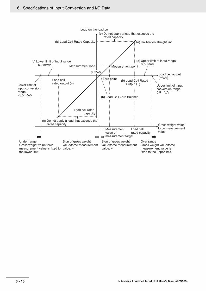
6 Specifications of Input Conversion and I/O Data
6 - 10 NX-series Load Cell Input Unit User’s Manual (W565)
(b) Load Cell Rated Capacity
0
0 mV/V
Measurement point
Zero point
Measurement load
Upper limit of input conversion range5.5 mV/V
Gross weight value/force measurement value
(a) Calibration straight line
Load cell rated capacity
Load on the load cell
Load cell rated capacity
Measurement value of measurement target
(b) Load Cell Zero Balance
Lower limit of input conversion range−5.5 mV/V
Load cell rated output (−)
Load cell output[mV/V]
(b) Load Cell Rated Output (+)
(c) Upper limit of input range5.0 mV/V
(c) Lower limit of input range−5.0 mV/V
(e) Do not apply a load that exceeds the rated capacity.
(e) Do not apply a load that exceeds the rated capacity.
Sign of gross weight value/force measurement value: −
Sign of gross weight value/force measurement value: +
Under range Gross weight value/force measurement value is fixed to the lower limit.
Over range Gross weight value/force measurement value is fixed to the upper limit.
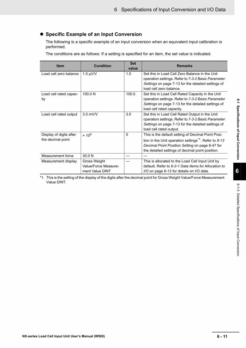
6 - 11
6 Specifications of Input Conversion and I/O Data
NX-series Load Cell Input Unit User’s Manual (W565)
6-1 Sp
ecificatio
ns o
f Inp
ut C
on
version
6
6-1-3 De
tailed Specification
s of Input C
onversion
Specific Example of an Input Conversion
The following is a specific example of an input conversion when an equivalent input calibration is performed.
The conditions are as follows: If a setting is specified for an item, the set value is indicated.
Item ConditionSet
valueRemarks
Load cell zero balance 1.0 μV/V 1.0 Set this in Load Cell Zero Balance in the Unit operation settings. Refer to 7-3-2 Basic Parameter Settings on page 7-13 for the detailed settings of load cell zero balance.
Load cell rated capac-ity
100.0 N 100.0 Set this in Load Cell Rated Capacity in the Unit operation settings. Refer to 7-3-2 Basic Parameter Settings on page 7-13 for the detailed settings of load cell rated capacity.
Load cell rated output 3.0 mV/V 3.0 Set this in Load Cell Rated Output in the Unit operation settings. Refer to 7-3-2 Basic Parameter Settings on page 7-13 for the detailed settings of load cell rated output.
Display of digits after the decimal point
× 100 0 This is the default setting of Decimal Point Posi-
tion in the Unit operation settings*1. Refer to 8-13 Decimal Point Position Setting on page 8-47 for the detailed settings of decimal point position.
*1. This is the setting of the display of the digits after the decimal point for Gross Weight Value/Force Measurement Value DINT.
Measurement force 30.0 N --- ---
Measurement display Gross Weight Value/Force Measure-ment Value DINT
--- This is allocated to the Load Cell Input Unit by default. Refer to 6-2-1 Data Items for Allocation to I/O on page 6-13 for details on I/O data.
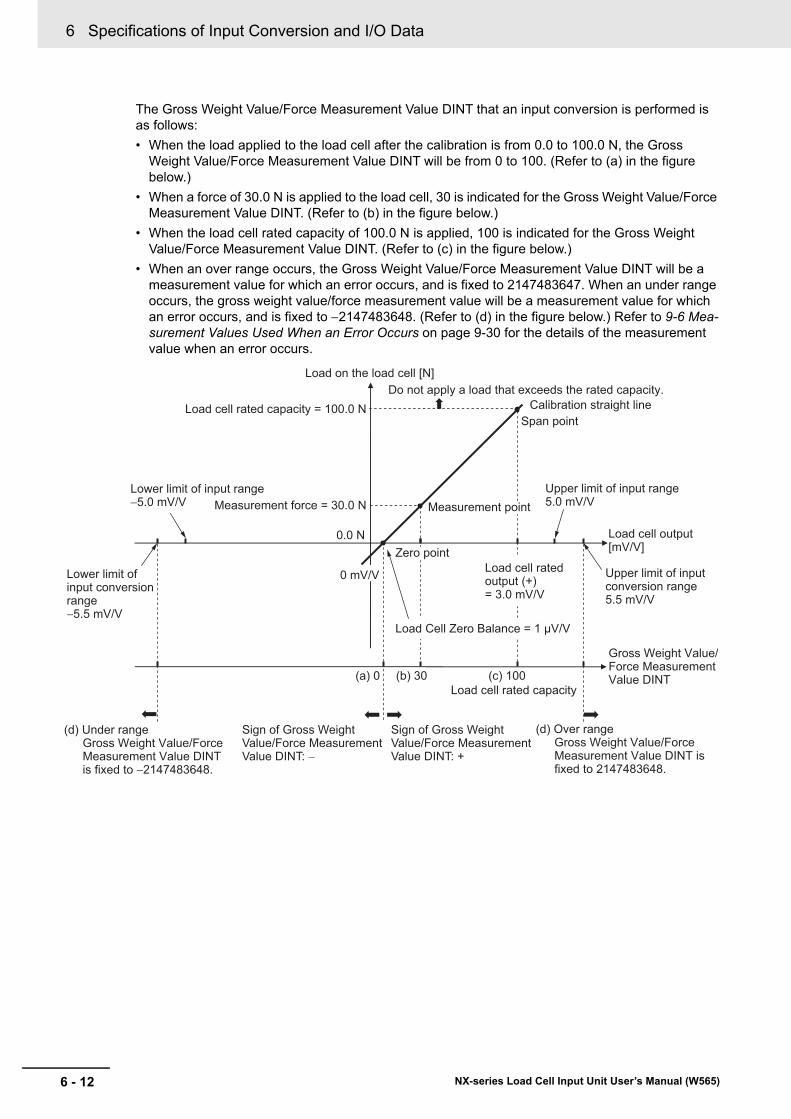
6 Specifications of Input Conversion and I/O Data
6 - 12 NX-series Load Cell Input Unit User’s Manual (W565)
The Gross Weight Value/Force Measurement Value DINT that an input conversion is performed is as follows:
• When the load applied to the load cell after the calibration is from 0.0 to 100.0 N, the Gross Weight Value/Force Measurement Value DINT will be from 0 to 100. (Refer to (a) in the figure below.)
• When a force of 30.0 N is applied to the load cell, 30 is indicated for the Gross Weight Value/Force Measurement Value DINT. (Refer to (b) in the figure below.)
• When the load cell rated capacity of 100.0 N is applied, 100 is indicated for the Gross Weight Value/Force Measurement Value DINT. (Refer to (c) in the figure below.)
• When an over range occurs, the Gross Weight Value/Force Measurement Value DINT will be a measurement value for which an error occurs, and is fixed to 2147483647. When an under range occurs, the gross weight value/force measurement value will be a measurement value for which an error occurs, and is fixed to 2147483648. (Refer to (d) in the figure below.) Refer to 9-6 Mea-surement Values Used When an Error Occurs on page 9-30 for the details of the measurement value when an error occurs.
Load cell rated capacity = 100.0 N
(a) 0
0 mV/V
0.0 N
Do not apply a load that exceeds the rated capacity.
Measurement point
Zero point
Measurement force = 30.0 NUpper limit of input range5.0 mV/V
Calibration straight line
Load cell rated output (+)= 3.0 mV/V
Load cell rated capacity
Load Cell Zero Balance = 1 μV/V
Load on the load cell [N]
Span point
Lower limit of input range−5.0 mV/V
Gross Weight Value/Force MeasurementValue DINT
Load cell output[mV/V]
(d) Under range Gross Weight Value/ForceMeasurement Value DINT is fixed to −2147483648.
(d) Over range Gross Weight Value/ForceMeasurement Value DINT is fixed to 2147483648.
Sign of Gross WeightValue/Force MeasurementValue DINT: −
Sign of Gross WeightValue/Force MeasurementValue DINT: +
Upper limit of input conversion range5.5 mV/V
Lower limit of input conversion range−5.5 mV/V
(b) 30 (c) 100
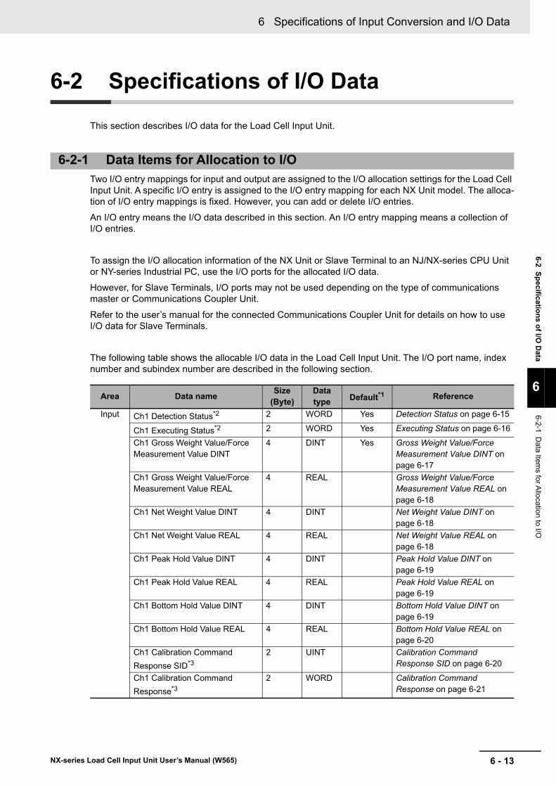
6 - 13
6 Specifications of Input Conversion and I/O Data
NX-series Load Cell Input Unit User’s Manual (W565)
6-2 S
pecificatio
ns o
f I/O D
ata
6
6-2-1 Da
ta Items for A
llocation to I/O
6-2 Specifications of I/O Data
This section describes I/O data for the Load Cell Input Unit.
Two I/O entry mappings for input and output are assigned to the I/O allocation settings for the Load Cell Input Unit. A specific I/O entry is assigned to the I/O entry mapping for each NX Unit model. The alloca-tion of I/O entry mappings is fixed. However, you can add or delete I/O entries.
An I/O entry means the I/O data described in this section. An I/O entry mapping means a collection of I/O entries.
To assign the I/O allocation information of the NX Unit or Slave Terminal to an NJ/NX-series CPU Unit or NY-series Industrial PC, use the I/O ports for the allocated I/O data.
However, for Slave Terminals, I/O ports may not be used depending on the type of communications master or Communications Coupler Unit.
Refer to the user’s manual for the connected Communications Coupler Unit for details on how to use I/O data for Slave Terminals.
The following table shows the allocable I/O data in the Load Cell Input Unit. The I/O port name, index number and subindex number are described in the following section.
6-2-1 Data Items for Allocation to I/O
Area Data nameSize
(Byte)Data type Default*1 Reference
Input Ch1 Detection Status*2 2 WORD Yes Detection Status on page 6-15
Ch1 Executing Status*2 2 WORD Yes Executing Status on page 6-16
Ch1 Gross Weight Value/Force Measurement Value DINT
4 DINT Yes Gross Weight Value/Force Measurement Value DINT on page 6-17
Ch1 Gross Weight Value/Force Measurement Value REAL
4 REAL Gross Weight Value/Force Measurement Value REAL on page 6-18
Ch1 Net Weight Value DINT 4 DINT Net Weight Value DINT on page 6-18
Ch1 Net Weight Value REAL 4 REAL Net Weight Value REAL on page 6-18
Ch1 Peak Hold Value DINT 4 DINT Peak Hold Value DINT on page 6-19
Ch1 Peak Hold Value REAL 4 REAL Peak Hold Value REAL on page 6-19
Ch1 Bottom Hold Value DINT 4 DINT Bottom Hold Value DINT on page 6-19
Ch1 Bottom Hold Value REAL 4 REAL Bottom Hold Value REAL on page 6-20
Ch1 Calibration Command
Response SID*3
2 UINT Calibration Command Response SID on page 6-20
Ch1 Calibration Command
Response*3
2 WORD Calibration Command Response on page 6-21
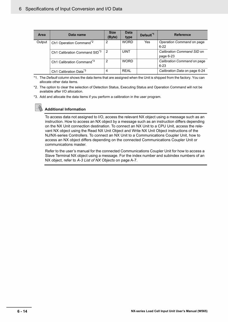
6 Specifications of Input Conversion and I/O Data
6 - 14 NX-series Load Cell Input Unit User’s Manual (W565)
Additional Information
To access data not assigned to I/O, access the relevant NX object using a message such as an instruction. How to access an NX object by a message such as an instruction differs depending on the NX Unit connection destination. To connect an NX Unit to a CPU Unit, access the rele-vant NX object using the Read NX Unit Object and Write NX Unit Object instructions of the NJ/NX-series Controllers. To connect an NX Unit to a Communications Coupler Unit, how to access an NX object differs depending on the connected Communications Coupler Unit or communications master.
Refer to the user’s manual for the connected Communications Coupler Unit for how to access a Slave Terminal NX object using a message. For the index number and subindex numbers of an NX object, refer to A-3 List of NX Objects on page A-7.
Output Ch1 Operation Command*2 2 WORD Yes Operation Command on page 6-22
Ch1 Calibration Command SID*3 2 UINT Calibration Command SID on page 6-23
Ch1 Calibration Command*3 2 WORD Calibration Command on page 6-23
Ch1 Calibration Data*3 4 REAL Calibration Data on page 6-24
*1. The Default column shows the data items that are assigned when the Unit is shipped from the factory. You can allocate other data items.
*2. The option to clear the selection of Detection Status, Executing Status and Operation Command will not be available after I/O allocation.
*3. Add and allocate the data items if you perform a calibration in the user program.
Area Data nameSize
(Byte)Data type Default*1 Reference
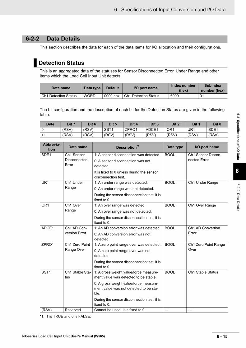
6 - 15
6 Specifications of Input Conversion and I/O Data
NX-series Load Cell Input Unit User’s Manual (W565)
6-2 S
pecificatio
ns o
f I/O D
ata
6
6-2-2 Da
ta Details
This section describes the data for each of the data items for I/O allocation and their configurations.
This is an aggregated data of the statuses for Sensor Disconnected Error, Under Range and other items which the Load Cell Input Unit detects.
The bit configuration and the description of each bit for the Detection Status are given in the following table.
6-2-2 Data Details
Detection Status
Data name Data type Default I/O port nameIndex number
(hex)Subindex
number (hex)
Ch1 Detection Status WORD 0000 hex Ch1 Detection Status 6000 01
Byte Bit 7 Bit 6 Bit 5 Bit 4 Bit 3 Bit 2 Bit 1 Bit 0
0 (RSV) (RSV) SST1 ZPRO1 ADCE1 OR1 UR1 SDE1
+1 (RSV) (RSV) (RSV) (RSV) (RSV) (RSV) (RSV) (RSV)
Abbrevia-tion
Data name Description*1
*1. 1 is TRUE and 0 is FALSE.
Data type I/O port name
SDE1 Ch1 Sensor Disconnected Error
1: A sensor disconnection was detected.
0: A sensor disconnection was not detected.
It is fixed to 0 unless during the sensor disconnection test.
BOOL Ch1 Sensor Discon-nected Error
UR1 Ch1 Under Range
1: An under range was detected.
0: An under range was not detected.
During the sensor disconnection test, it is fixed to 0.
BOOL Ch1 Under Range
OR1 Ch1 Over Range
1: An over range was detected.
0: An over range was not detected.
During the sensor disconnection test, it is fixed to 0.
BOOL Ch1 Over Range
ADCE1 Ch1 AD Con-version Error
1: An AD conversion error was detected.
0: An AD conversion error was not detected.
BOOL Ch1 AD Convertion Error
ZPRO1 Ch1 Zero Point Range Over
1: A zero point range over was detected.
0: A zero point range over was not detected.
During the sensor disconnection test, it is fixed to 0.
BOOL Ch1 Zero Point Range Over
SST1 Ch1 Stable Sta-tus
1: A gross weight value/force measure-ment value was detected to be stable.
0: A gross weight value/force measure-ment value was not detected to be sta-ble.
During the sensor disconnection test, it is fixed to 0.
BOOL Ch1 Stable Status
(RSV) Reserved Cannot be used. It is fixed to 0. --- ---
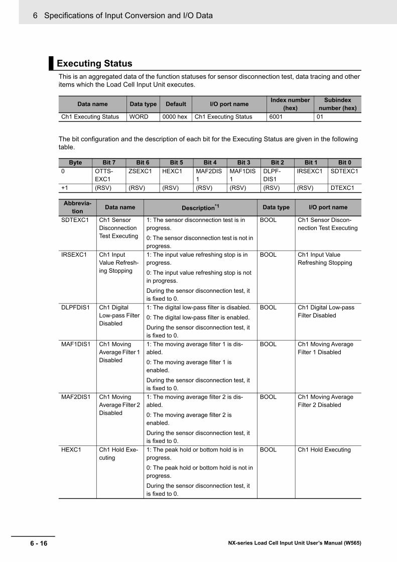
6 Specifications of Input Conversion and I/O Data
6 - 16 NX-series Load Cell Input Unit User’s Manual (W565)
This is an aggregated data of the function statuses for sensor disconnection test, data tracing and other items which the Load Cell Input Unit executes.
The bit configuration and the description of each bit for the Executing Status are given in the following table.
Executing Status
Data name Data type Default I/O port nameIndex number
(hex)Subindex
number (hex)
Ch1 Executing Status WORD 0000 hex Ch1 Executing Status 6001 01
Byte Bit 7 Bit 6 Bit 5 Bit 4 Bit 3 Bit 2 Bit 1 Bit 0
0 OTTS-EXC1
ZSEXC1 HEXC1 MAF2DIS1
MAF1DIS1
DLPF-DIS1
IRSEXC1 SDTEXC1
+1 (RSV) (RSV) (RSV) (RSV) (RSV) (RSV) (RSV) DTEXC1
Abbrevia-tion
Data name Description*1 Data type I/O port name
SDTEXC1 Ch1 Sensor Disconnection Test Executing
1: The sensor disconnection test is in progress.
0: The sensor disconnection test is not in progress.
BOOL Ch1 Sensor Discon-nection Test Executing
IRSEXC1 Ch1 Input Value Refresh-ing Stopping
1: The input value refreshing stop is in progress.
0: The input value refreshing stop is not in progress.
During the sensor disconnection test, it is fixed to 0.
BOOL Ch1 Input Value Refreshing Stopping
DLPFDIS1 Ch1 Digital Low-pass Filter Disabled
1: The digital low-pass filter is disabled.
0: The digital low-pass filter is enabled.
During the sensor disconnection test, it is fixed to 0.
BOOL Ch1 Digital Low-pass Filter Disabled
MAF1DIS1 Ch1 Moving Average Filter 1 Disabled
1: The moving average filter 1 is dis-abled.
0: The moving average filter 1 is enabled.
During the sensor disconnection test, it is fixed to 0.
BOOL Ch1 Moving Average Filter 1 Disabled
MAF2DIS1 Ch1 Moving Average Filter 2 Disabled
1: The moving average filter 2 is dis-abled.
0: The moving average filter 2 is enabled.
During the sensor disconnection test, it is fixed to 0.
BOOL Ch1 Moving Average Filter 2 Disabled
HEXC1 Ch1 Hold Exe-cuting
1: The peak hold or bottom hold is in progress.
0: The peak hold or bottom hold is not in progress.
During the sensor disconnection test, it is fixed to 0.
BOOL Ch1 Hold Executing
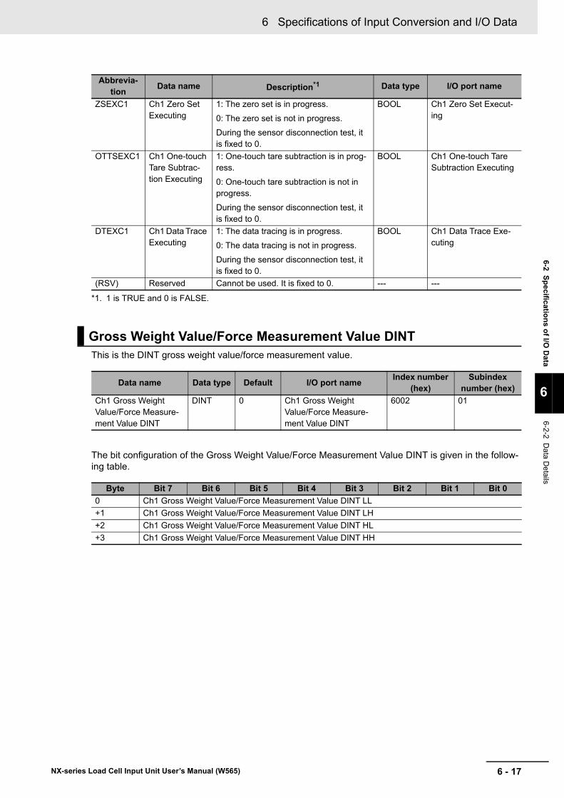
6 - 17
6 Specifications of Input Conversion and I/O Data
NX-series Load Cell Input Unit User’s Manual (W565)
6-2 S
pecificatio
ns o
f I/O D
ata
6
6-2-2 Da
ta Details
This is the DINT gross weight value/force measurement value.
The bit configuration of the Gross Weight Value/Force Measurement Value DINT is given in the follow-ing table.
ZSEXC1 Ch1 Zero Set Executing
1: The zero set is in progress.
0: The zero set is not in progress.
During the sensor disconnection test, it is fixed to 0.
BOOL Ch1 Zero Set Execut-ing
OTTSEXC1 Ch1 One-touch Tare Subtrac-tion Executing
1: One-touch tare subtraction is in prog-ress.
0: One-touch tare subtraction is not in progress.
During the sensor disconnection test, it is fixed to 0.
BOOL Ch1 One-touch Tare Subtraction Executing
DTEXC1 Ch1 Data Trace Executing
1: The data tracing is in progress.
0: The data tracing is not in progress.
During the sensor disconnection test, it is fixed to 0.
BOOL Ch1 Data Trace Exe-cuting
(RSV) Reserved Cannot be used. It is fixed to 0. --- ---
*1. 1 is TRUE and 0 is FALSE.
Gross Weight Value/Force Measurement Value DINT
Data name Data type Default I/O port nameIndex number
(hex)Subindex
number (hex)
Ch1 Gross Weight Value/Force Measure-ment Value DINT
DINT 0 Ch1 Gross Weight Value/Force Measure-ment Value DINT
6002 01
Byte Bit 7 Bit 6 Bit 5 Bit 4 Bit 3 Bit 2 Bit 1 Bit 0
0 Ch1 Gross Weight Value/Force Measurement Value DINT LL
+1 Ch1 Gross Weight Value/Force Measurement Value DINT LH
+2 Ch1 Gross Weight Value/Force Measurement Value DINT HL
+3 Ch1 Gross Weight Value/Force Measurement Value DINT HH
Abbrevia-tion
Data name Description*1 Data type I/O port name
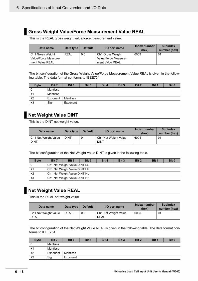
6 Specifications of Input Conversion and I/O Data
6 - 18 NX-series Load Cell Input Unit User’s Manual (W565)
This is the REAL gross weight value/force measurement value.
The bit configuration of the Gross Weight Value/Force Measurement Value REAL is given in the follow-ing table. The data format conforms to IEEE754.
This is the DINT net weight value.
The bit configuration of the Net Weight Value DINT is given in the following table.
This is the REAL net weight value.
The bit configuration of the Net Weight Value REAL is given in the following table. The data format con-forms to IEEE754.
Gross Weight Value/Force Measurement Value REAL
Data name Data type Default I/O port nameIndex number
(hex)Subindex
number (hex)
Ch1 Gross Weight Value/Force Measure-ment Value REAL
REAL 0.0 Ch1 Gross Weight Value/Force Measure-ment Value REAL
6003 01
Byte Bit 7 Bit 6 Bit 5 Bit 4 Bit 3 Bit 2 Bit 1 Bit 0
0 Mantissa
+1 Mantissa
+2 Exponent Mantissa
+3 Sign Exponent
Net Weight Value DINT
Data name Data type Default I/O port nameIndex number
(hex)Subindex
number (hex)
Ch1 Net Weight Value DINT
DINT 0 Ch1 Net Weight Value DINT
6004 01
Byte Bit 7 Bit 6 Bit 5 Bit 4 Bit 3 Bit 2 Bit 1 Bit 0
0 Ch1 Net Weight Value DINT LL
+1 Ch1 Net Weight Value DINT LH
+2 Ch1 Net Weight Value DINT HL
+3 Ch1 Net Weight Value DINT HH
Net Weight Value REAL
Data name Data type Default I/O port nameIndex number
(hex)Subindex
number (hex)
Ch1 Net Weight Value REAL
REAL 0.0 Ch1 Net Weight Value REAL
6005 01
Byte Bit 7 Bit 6 Bit 5 Bit 4 Bit 3 Bit 2 Bit 1 Bit 0
0 Mantissa
+1 Mantissa
+2 Exponent Mantissa
+3 Sign Exponent
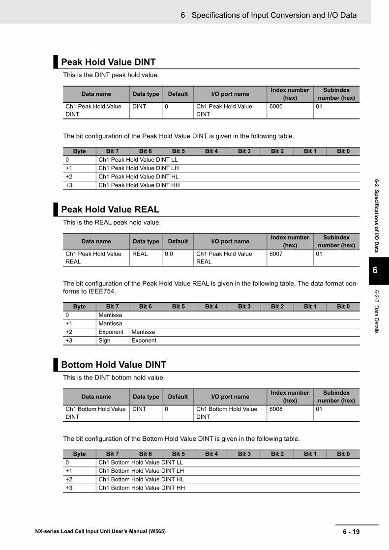
6 - 19
6 Specifications of Input Conversion and I/O Data
NX-series Load Cell Input Unit User’s Manual (W565)
6-2 S
pecificatio
ns o
f I/O D
ata
6
6-2-2 Da
ta Details
This is the DINT peak hold value.
The bit configuration of the Peak Hold Value DINT is given in the following table.
This is the REAL peak hold value.
The bit configuration of the Peak Hold Value REAL is given in the following table. The data format con-forms to IEEE754.
This is the DINT bottom hold value.
The bit configuration of the Bottom Hold Value DINT is given in the following table.
Peak Hold Value DINT
Data name Data type Default I/O port nameIndex number
(hex)Subindex
number (hex)
Ch1 Peak Hold Value DINT
DINT 0 Ch1 Peak Hold Value DINT
6006 01
Byte Bit 7 Bit 6 Bit 5 Bit 4 Bit 3 Bit 2 Bit 1 Bit 0
0 Ch1 Peak Hold Value DINT LL
+1 Ch1 Peak Hold Value DINT LH
+2 Ch1 Peak Hold Value DINT HL
+3 Ch1 Peak Hold Value DINT HH
Peak Hold Value REAL
Data name Data type Default I/O port nameIndex number
(hex)Subindex
number (hex)
Ch1 Peak Hold Value REAL
REAL 0.0 Ch1 Peak Hold Value REAL
6007 01
Byte Bit 7 Bit 6 Bit 5 Bit 4 Bit 3 Bit 2 Bit 1 Bit 0
0 Mantissa
+1 Mantissa
+2 Exponent Mantissa
+3 Sign Exponent
Bottom Hold Value DINT
Data name Data type Default I/O port nameIndex number
(hex)Subindex
number (hex)
Ch1 Bottom Hold Value DINT
DINT 0 Ch1 Bottom Hold Value DINT
6008 01
Byte Bit 7 Bit 6 Bit 5 Bit 4 Bit 3 Bit 2 Bit 1 Bit 0
0 Ch1 Bottom Hold Value DINT LL
+1 Ch1 Bottom Hold Value DINT LH
+2 Ch1 Bottom Hold Value DINT HL
+3 Ch1 Bottom Hold Value DINT HH
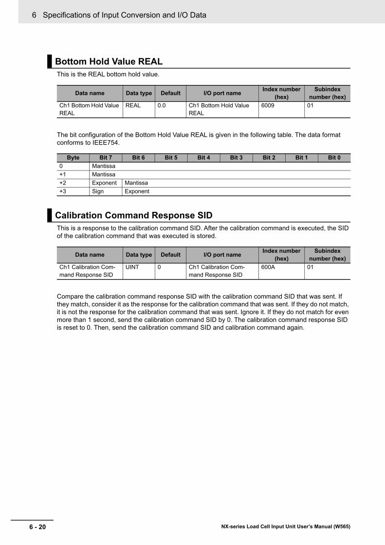
6 Specifications of Input Conversion and I/O Data
6 - 20 NX-series Load Cell Input Unit User’s Manual (W565)
This is the REAL bottom hold value.
The bit configuration of the Bottom Hold Value REAL is given in the following table. The data format conforms to IEEE754.
This is a response to the calibration command SID. After the calibration command is executed, the SID of the calibration command that was executed is stored.
Compare the calibration command response SID with the calibration command SID that was sent. If they match, consider it as the response for the calibration command that was sent. If they do not match, it is not the response for the calibration command that was sent. Ignore it. If they do not match for even more than 1 second, send the calibration command SID by 0. The calibration command response SID is reset to 0. Then, send the calibration command SID and calibration command again.
Bottom Hold Value REAL
Data name Data type Default I/O port nameIndex number
(hex)Subindex
number (hex)
Ch1 Bottom Hold Value REAL
REAL 0.0 Ch1 Bottom Hold Value REAL
6009 01
Byte Bit 7 Bit 6 Bit 5 Bit 4 Bit 3 Bit 2 Bit 1 Bit 0
0 Mantissa
+1 Mantissa
+2 Exponent Mantissa
+3 Sign Exponent
Calibration Command Response SID
Data name Data type Default I/O port nameIndex number
(hex)Subindex
number (hex)
Ch1 Calibration Com-mand Response SID
UINT 0 Ch1 Calibration Com-mand Response SID
600A 01
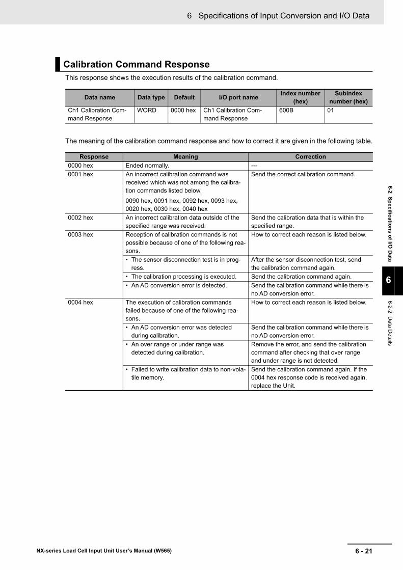
6 - 21
6 Specifications of Input Conversion and I/O Data
NX-series Load Cell Input Unit User’s Manual (W565)
6-2 S
pecificatio
ns o
f I/O D
ata
6
6-2-2 Da
ta Details
This response shows the execution results of the calibration command.
The meaning of the calibration command response and how to correct it are given in the following table.
Calibration Command Response
Data name Data type Default I/O port nameIndex number
(hex)Subindex
number (hex)
Ch1 Calibration Com-mand Response
WORD 0000 hex Ch1 Calibration Com-mand Response
600B 01
Response Meaning Correction
0000 hex Ended normally. ---
0001 hex An incorrect calibration command was received which was not among the calibra-tion commands listed below.
0090 hex, 0091 hex, 0092 hex, 0093 hex, 0020 hex, 0030 hex, 0040 hex
Send the correct calibration command.
0002 hex An incorrect calibration data outside of the specified range was received.
Send the calibration data that is within the specified range.
0003 hex Reception of calibration commands is not possible because of one of the following rea-sons.
How to correct each reason is listed below.
• The sensor disconnection test is in prog-ress.
After the sensor disconnection test, send the calibration command again.
• The calibration processing is executed. Send the calibration command again.
• An AD conversion error is detected. Send the calibration command while there is no AD conversion error.
0004 hex The execution of calibration commands failed because of one of the following rea-sons.
How to correct each reason is listed below.
• An AD conversion error was detected during calibration.
Send the calibration command while there is no AD conversion error.
• An over range or under range was detected during calibration.
Remove the error, and send the calibration command after checking that over range and under range is not detected.
• Failed to write calibration data to non-vola-tile memory.
Send the calibration command again. If the 0004 hex response code is received again, replace the Unit.
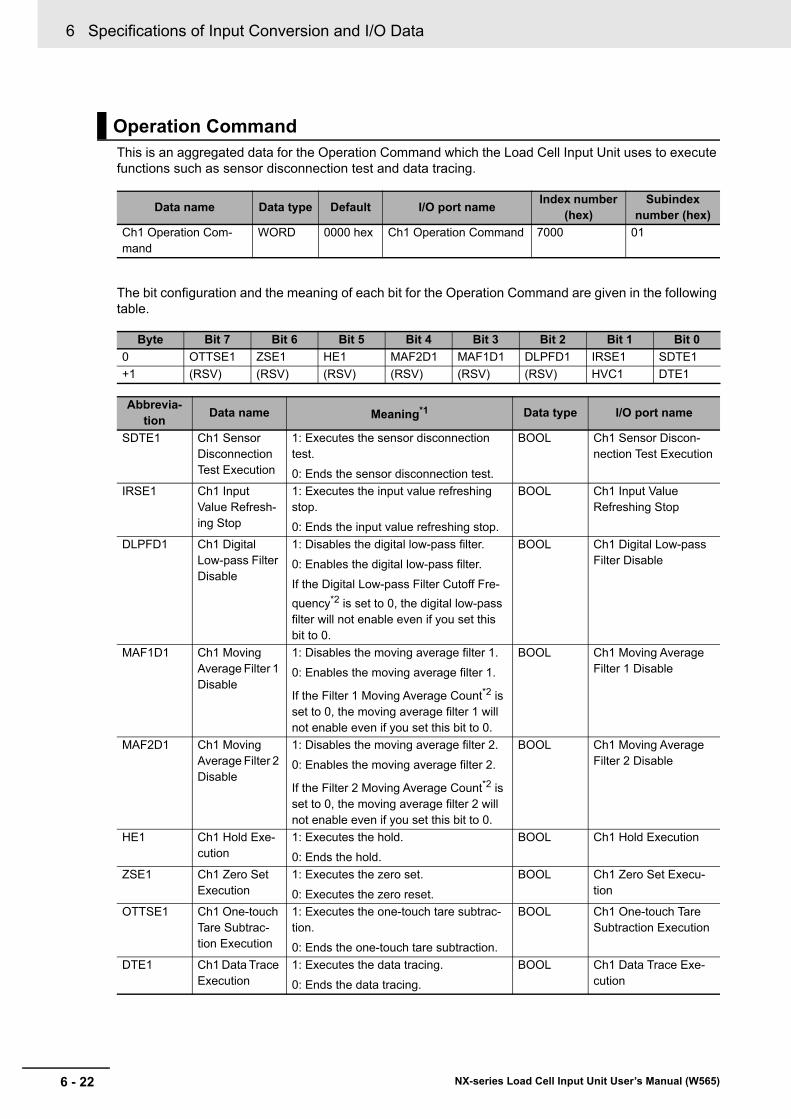
6 Specifications of Input Conversion and I/O Data
6 - 22 NX-series Load Cell Input Unit User’s Manual (W565)
This is an aggregated data for the Operation Command which the Load Cell Input Unit uses to execute functions such as sensor disconnection test and data tracing.
The bit configuration and the meaning of each bit for the Operation Command are given in the following table.
Operation Command
Data name Data type Default I/O port nameIndex number
(hex)Subindex
number (hex)
Ch1 Operation Com-mand
WORD 0000 hex Ch1 Operation Command 7000 01
Byte Bit 7 Bit 6 Bit 5 Bit 4 Bit 3 Bit 2 Bit 1 Bit 0
0 OTTSE1 ZSE1 HE1 MAF2D1 MAF1D1 DLPFD1 IRSE1 SDTE1
+1 (RSV) (RSV) (RSV) (RSV) (RSV) (RSV) HVC1 DTE1
Abbrevia-tion
Data name Meaning*1 Data type I/O port name
SDTE1 Ch1 Sensor Disconnection Test Execution
1: Executes the sensor disconnection test.
0: Ends the sensor disconnection test.
BOOL Ch1 Sensor Discon-nection Test Execution
IRSE1 Ch1 Input Value Refresh-ing Stop
1: Executes the input value refreshing stop.
0: Ends the input value refreshing stop.
BOOL Ch1 Input Value Refreshing Stop
DLPFD1 Ch1 Digital Low-pass Filter Disable
1: Disables the digital low-pass filter.
0: Enables the digital low-pass filter.
If the Digital Low-pass Filter Cutoff Fre-
quency*2 is set to 0, the digital low-pass filter will not enable even if you set this bit to 0.
BOOL Ch1 Digital Low-pass Filter Disable
MAF1D1 Ch1 Moving Average Filter 1 Disable
1: Disables the moving average filter 1.
0: Enables the moving average filter 1.
If the Filter 1 Moving Average Count*2 is set to 0, the moving average filter 1 will not enable even if you set this bit to 0.
BOOL Ch1 Moving Average Filter 1 Disable
MAF2D1 Ch1 Moving Average Filter 2 Disable
1: Disables the moving average filter 2.
0: Enables the moving average filter 2.
If the Filter 2 Moving Average Count*2 is set to 0, the moving average filter 2 will not enable even if you set this bit to 0.
BOOL Ch1 Moving Average Filter 2 Disable
HE1 Ch1 Hold Exe-cution
1: Executes the hold.
0: Ends the hold.
BOOL Ch1 Hold Execution
ZSE1 Ch1 Zero Set Execution
1: Executes the zero set.
0: Executes the zero reset.
BOOL Ch1 Zero Set Execu-tion
OTTSE1 Ch1 One-touch Tare Subtrac-tion Execution
1: Executes the one-touch tare subtrac-tion.
0: Ends the one-touch tare subtraction.
BOOL Ch1 One-touch Tare Subtraction Execution
DTE1 Ch1 Data Trace Execution
1: Executes the data tracing.
0: Ends the data tracing.
BOOL Ch1 Data Trace Exe-cution
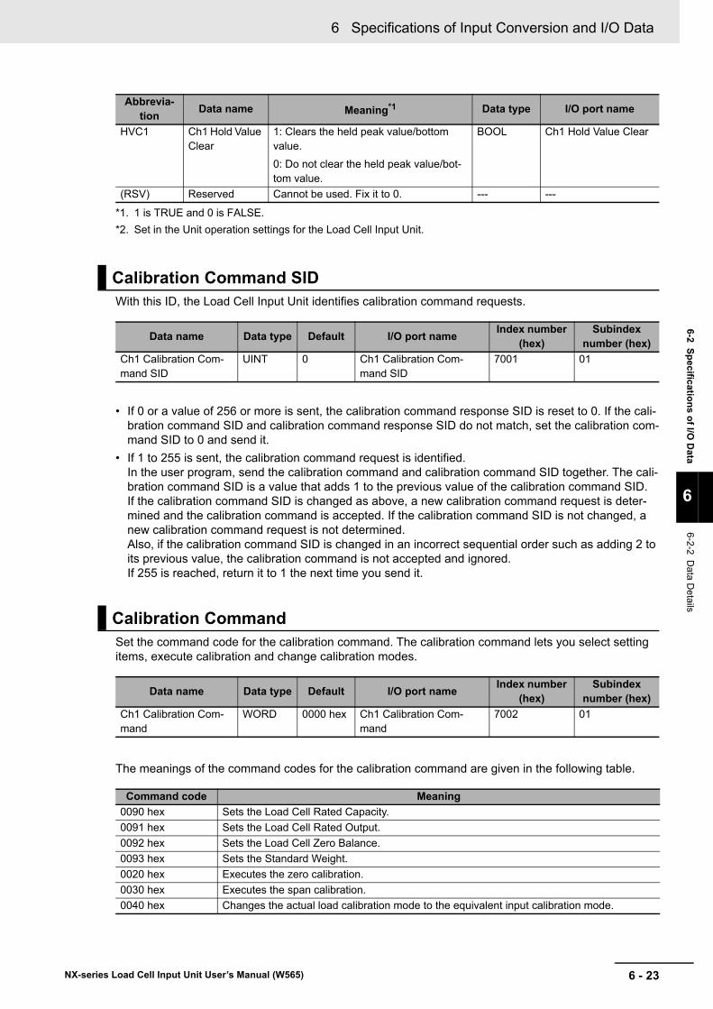
6 - 23
6 Specifications of Input Conversion and I/O Data
NX-series Load Cell Input Unit User’s Manual (W565)
6-2 S
pecificatio
ns o
f I/O D
ata
6
6-2-2 Da
ta Details
With this ID, the Load Cell Input Unit identifies calibration command requests.
• If 0 or a value of 256 or more is sent, the calibration command response SID is reset to 0. If the cali-bration command SID and calibration command response SID do not match, set the calibration com-mand SID to 0 and send it.
• If 1 to 255 is sent, the calibration command request is identified. In the user program, send the calibration command and calibration command SID together. The cali-bration command SID is a value that adds 1 to the previous value of the calibration command SID. If the calibration command SID is changed as above, a new calibration command request is deter-mined and the calibration command is accepted. If the calibration command SID is not changed, a new calibration command request is not determined. Also, if the calibration command SID is changed in an incorrect sequential order such as adding 2 to its previous value, the calibration command is not accepted and ignored. If 255 is reached, return it to 1 the next time you send it.
Set the command code for the calibration command. The calibration command lets you select setting items, execute calibration and change calibration modes.
The meanings of the command codes for the calibration command are given in the following table.
HVC1 Ch1 Hold Value Clear
1: Clears the held peak value/bottom value.
0: Do not clear the held peak value/bot-tom value.
BOOL Ch1 Hold Value Clear
(RSV) Reserved Cannot be used. Fix it to 0. --- ---
*1. 1 is TRUE and 0 is FALSE.
*2. Set in the Unit operation settings for the Load Cell Input Unit.
Calibration Command SID
Data name Data type Default I/O port nameIndex number
(hex)Subindex
number (hex)
Ch1 Calibration Com-mand SID
UINT 0 Ch1 Calibration Com-mand SID
7001 01
Calibration Command
Data name Data type Default I/O port nameIndex number
(hex)Subindex
number (hex)
Ch1 Calibration Com-mand
WORD 0000 hex Ch1 Calibration Com-mand
7002 01
Command code Meaning
0090 hex Sets the Load Cell Rated Capacity.
0091 hex Sets the Load Cell Rated Output.
0092 hex Sets the Load Cell Zero Balance.
0093 hex Sets the Standard Weight.
0020 hex Executes the zero calibration.
0030 hex Executes the span calibration.
0040 hex Changes the actual load calibration mode to the equivalent input calibration mode.
Abbrevia-tion
Data name Meaning*1 Data type I/O port name
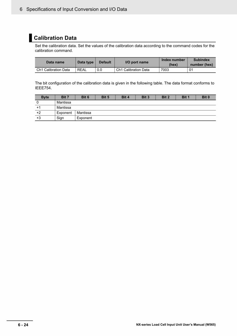
6 Specifications of Input Conversion and I/O Data
6 - 24 NX-series Load Cell Input Unit User’s Manual (W565)
Set the calibration data. Set the values of the calibration data according to the command codes for the calibration command.
The bit configuration of the calibration data is given in the following table. The data format conforms to IEEE754.
Calibration Data
Data name Data type Default I/O port nameIndex number
(hex)Subindex
number (hex)
Ch1 Calibration Data REAL 0.0 Ch1 Calibration Data 7003 01
Byte Bit 7 Bit 6 Bit 5 Bit 4 Bit 3 Bit 2 Bit 1 Bit 0
0 Mantissa
+1 Mantissa
+2 Exponent Mantissa
+3 Sign Exponent
7 - 1
7
NX-series Load Cell Input Unit User’s Manual (W565)
This section describes the methods of calibrating the Load Cell Input Unit.
7-1 Overview and Precautions . . . . . . . . . . . . . . . . . . . . . . . . . . . . . . . . . . . . . . 7-27-1-1 Overview of Actual Load Calibration and Equivalent Input Calibration . . . . . . . 7-2
7-1-2 Precautions for Calibration . . . . . . . . . . . . . . . . . . . . . . . . . . . . . . . . . . . . . . . . 7-3
7-2 Actual Load Calibration . . . . . . . . . . . . . . . . . . . . . . . . . . . . . . . . . . . . . . . . . 7-47-2-1 Calibration Procedure . . . . . . . . . . . . . . . . . . . . . . . . . . . . . . . . . . . . . . . . . . . . 7-4
7-2-2 Basic Parameter Settings . . . . . . . . . . . . . . . . . . . . . . . . . . . . . . . . . . . . . . . . . 7-7
7-2-3 Performing a Zero Calibration . . . . . . . . . . . . . . . . . . . . . . . . . . . . . . . . . . . . . . 7-9
7-2-4 Performing a Span Calibration . . . . . . . . . . . . . . . . . . . . . . . . . . . . . . . . . . . . 7-10
7-2-5 Correcting Errors by Calibration Site . . . . . . . . . . . . . . . . . . . . . . . . . . . . . . . 7-10
7-3 Equivalent Input Calibration . . . . . . . . . . . . . . . . . . . . . . . . . . . . . . . . . . . . 7-117-3-1 Calibration Procedure . . . . . . . . . . . . . . . . . . . . . . . . . . . . . . . . . . . . . . . . . . . .7-11
7-3-2 Basic Parameter Settings . . . . . . . . . . . . . . . . . . . . . . . . . . . . . . . . . . . . . . . . 7-13
7-3-3 Changing Calibration Modes . . . . . . . . . . . . . . . . . . . . . . . . . . . . . . . . . . . . . 7-15
7-4 Calibration with the User Program . . . . . . . . . . . . . . . . . . . . . . . . . . . . . . . 7-167-4-1 Performing an Actual Load Calibration . . . . . . . . . . . . . . . . . . . . . . . . . . . . . . 7-16
7-4-2 Performing an Equivalent Input Calibration . . . . . . . . . . . . . . . . . . . . . . . . . . 7-32
7-5 Calibration Failures and Calibration Value Errors . . . . . . . . . . . . . . . . . . 7-457-5-1 Calibration Failures . . . . . . . . . . . . . . . . . . . . . . . . . . . . . . . . . . . . . . . . . . . . . 7-45
7-5-2 Calibration Value Errors . . . . . . . . . . . . . . . . . . . . . . . . . . . . . . . . . . . . . . . . . 7-48
Calibration Methods
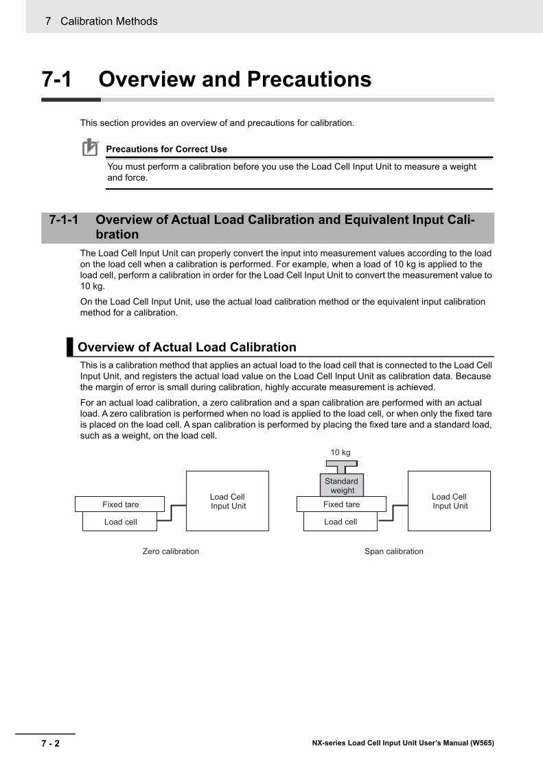
7 Calibration Methods
7 - 2 NX-series Load Cell Input Unit User’s Manual (W565)
7-1 Overview and Precautions
This section provides an overview of and precautions for calibration.
Precautions for Correct Use
You must perform a calibration before you use the Load Cell Input Unit to measure a weight and force.
The Load Cell Input Unit can properly convert the input into measurement values according to the load on the load cell when a calibration is performed. For example, when a load of 10 kg is applied to the load cell, perform a calibration in order for the Load Cell Input Unit to convert the measurement value to 10 kg.
On the Load Cell Input Unit, use the actual load calibration method or the equivalent input calibration method for a calibration.
This is a calibration method that applies an actual load to the load cell that is connected to the Load Cell Input Unit, and registers the actual load value on the Load Cell Input Unit as calibration data. Because the margin of error is small during calibration, highly accurate measurement is achieved.
For an actual load calibration, a zero calibration and a span calibration are performed with an actual load. A zero calibration is performed when no load is applied to the load cell, or when only the fixed tare is placed on the load cell. A span calibration is performed by placing the fixed tare and a standard load, such as a weight, on the load cell.
7-1-1 Overview of Actual Load Calibration and Equivalent Input Cali-bration
Overview of Actual Load Calibration
Load Cell Input Unit
Load Cell Input Unit
Load cell
Fixed tare Fixed tare
Load cell
Standard weight
10 kg
Zero calibration Span calibration
7 - 3
7 Calibration Methods
NX-series Load Cell Input Unit User’s Manual (W565)
7-1 O
verview an
d P
recautio
ns
7
7-1-2 P
recautions for C
alibration
This is a calibration method that sets the rated capacity, the rated output and the zero balance that are listed on the data sheet for the load cell by entering numeric values, and registers the values on the Load Cell Input Unit as calibration data.
Compared to an actual load calibration, the measurement resolution is lower because the margin of error is greater with this calibration. An equivalent input calibration is performed in the following cases:
• When measuring a force
• When measuring a material of a weight for which preparation of a standard weight is not possible
• When spatial limitation makes it difficult to apply an actual load, such as when the load cell and the filling machine are integrated.
When a zero balance is not listed on the data sheet for the load cell, perform one of the following:
• Contact the manufacturer of the load cell to obtain the zero balance value.
• Set the set value of the load cell zero balance to 0. To eliminate any impact of the zero balance, use the zero set to correct the zero point before you perform a measurement.
Precautions when performing a calibration are provided as follows:
• Perform an actual load calibration in the actual equipment system.
• Before you perform an actual load calibration, turn ON the power supply and warm-up the system for at least 30 minutes. If the system is not warmed up, the error by a zero drift or a gain drift after the calibration becomes greater than that of when the system is warmed up and the error of measure-ment values becomes larger.
• When you perform an actual load calibration for the first time, be sure to perform both a zero calibra-tion and a span calibration. If only one of them is performed, the measurement values are not con-verted properly.
• Check that there are no errors before you perform a calibration.
• The measurement values continue to be refreshed even during a calibration as they are during a nor-mal operation. The measurement values during a calibration are not accurately displayed until the calibration is completed.
• If a calibration fails, the calibration values are not recorded to the non-volatile memory of the Load Cell Input Unit. Remove the cause of the failure and perform the calibration again. Refer to 7-5 Cali-bration Failures and Calibration Value Errors on page 7-45 for details of calibration failure.
Overview of Equivalent Input Calibration
7-1-2 Precautions for Calibration
7 Calibration Methods
7 - 4 NX-series Load Cell Input Unit User’s Manual (W565)
7-2 Actual Load Calibration
This section describes an actual load calibration of the Load Cell Input Unit.
The calibration procedure varies depending on the following situations:
• When performing an actual load calibration for the first time
• When performing an actual load calibration again
The procedure of an actual load calibration for each situation is described.
7-2-1 Calibration Procedure
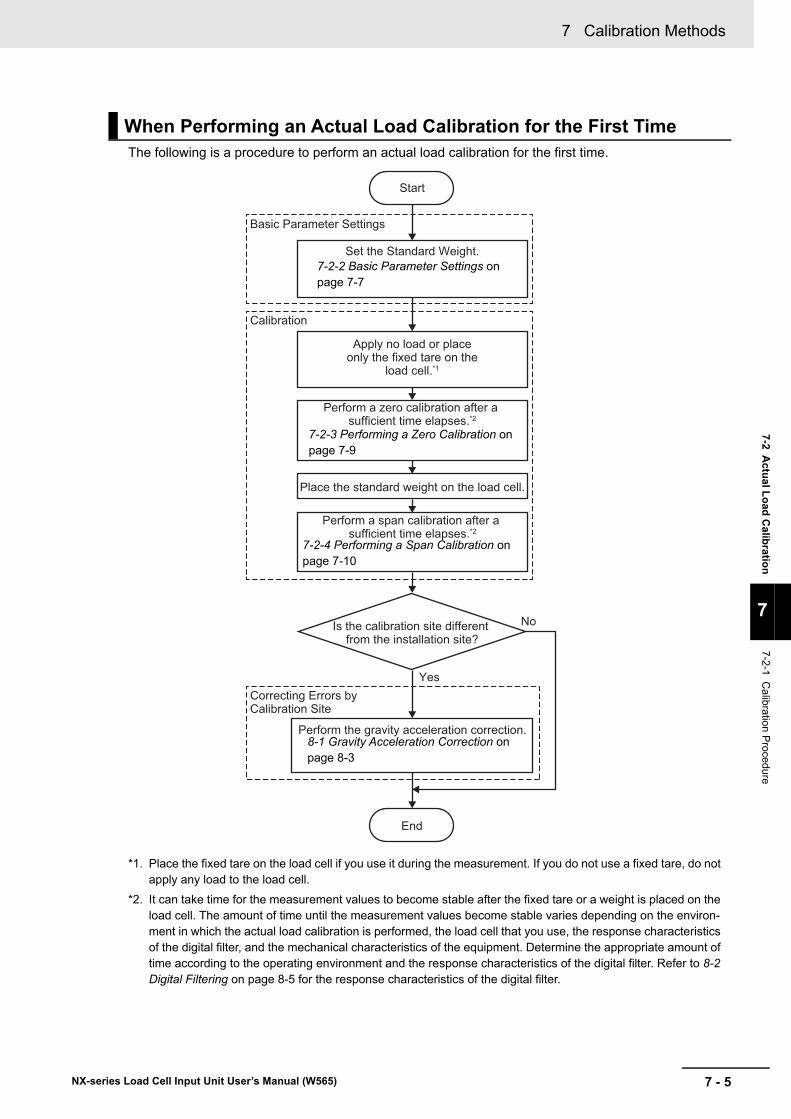
7 - 5
7 Calibration Methods
NX-series Load Cell Input Unit User’s Manual (W565)
7-2 Actu
al Lo
ad C
alibratio
n
7
7-2-1 C
alibration Procedure
The following is a procedure to perform an actual load calibration for the first time.
*1. Place the fixed tare on the load cell if you use it during the measurement. If you do not use a fixed tare, do not apply any load to the load cell.
*2. It can take time for the measurement values to become stable after the fixed tare or a weight is placed on the load cell. The amount of time until the measurement values become stable varies depending on the environ-ment in which the actual load calibration is performed, the load cell that you use, the response characteristics of the digital filter, and the mechanical characteristics of the equipment. Determine the appropriate amount of time according to the operating environment and the response characteristics of the digital filter. Refer to 8-2 Digital Filtering on page 8-5 for the response characteristics of the digital filter.
When Performing an Actual Load Calibration for the First Time
Set the Standard Weight.
Start
Perform a zero calibration after a sufficient time elapses.*2
Perform a span calibration after a sufficient time elapses.*2
Basic Parameter Settings
Is the calibration site different from the installation site?
Calibration
Perform the gravity acceleration correction.
Correcting Errors by Calibration Site
End
Yes
No
Place the standard weight on the load cell.
Apply no load or place only the fixed tare on the
load cell.*1
7-2-2 Basic Parameter Settings on page 7-7
7-2-3 Performing a Zero Calibration on page 7-9
7-2-4 Performing a Span Calibration on page 7-10
8-1 Gravity Acceleration Correction on page 8-3
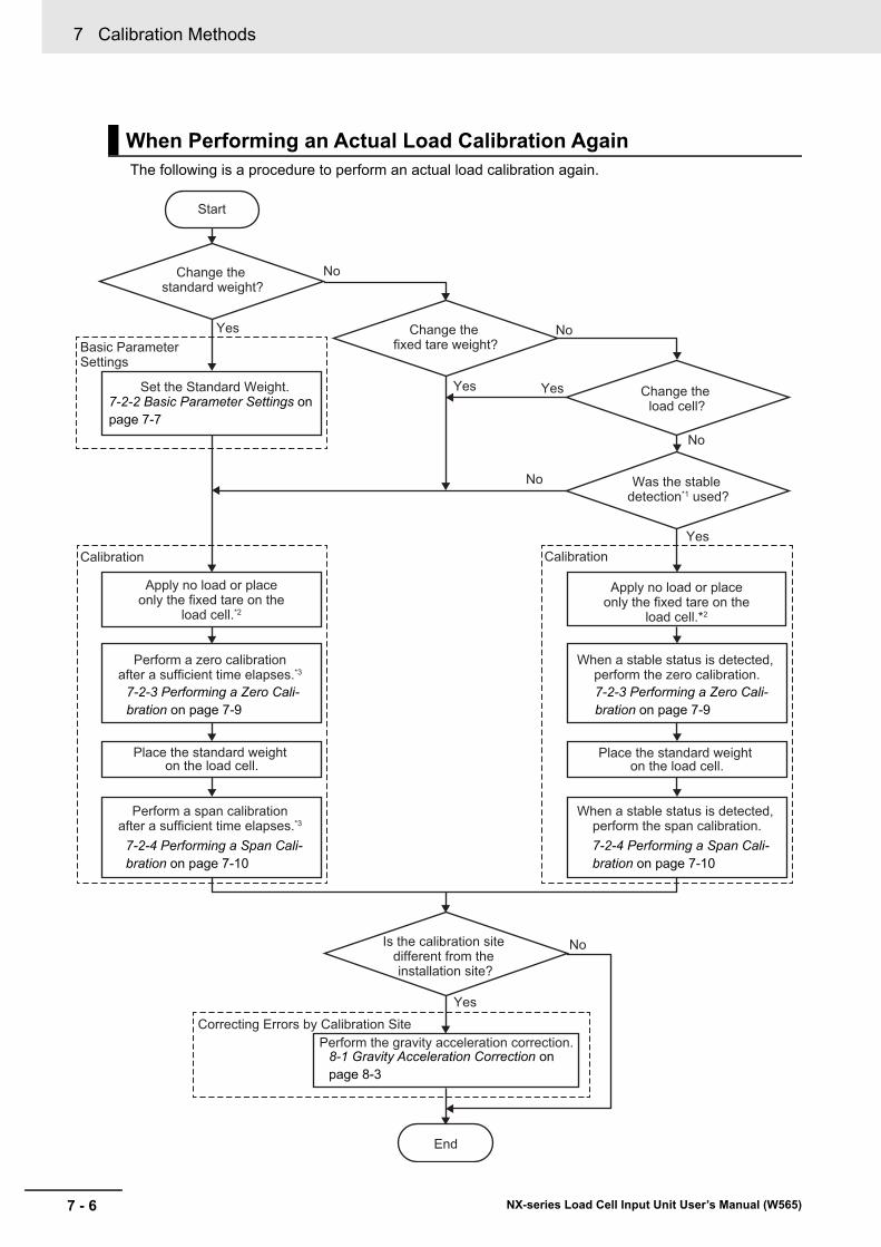
7 Calibration Methods
7 - 6 NX-series Load Cell Input Unit User’s Manual (W565)
The following is a procedure to perform an actual load calibration again.
When Performing an Actual Load Calibration Again
Change the standard weight?
Yes
No
Start
Basic Parameter Settings
Calibration Calibration
Was the stable detection*1 used?
Set the Standard Weight.
Perform a zero calibration after a sufficient time elapses.*3
Perform a span calibration after a sufficient time elapses.*3
Place the standard weight on the load cell.
When a stable status is detected, perform the zero calibration.
When a stable status is detected, perform the span calibration.
Place the standard weight on the load cell.
Change the fixed tare weight?
Change the load cell?
Yes Yes
Yes
No
No
No
Perform the gravity acceleration correction.Correcting Errors by Calibration Site
Yes
NoIs the calibration site different from the installation site?
Apply no load or place only the fixed tare on the
load cell.*2
Apply no load or place only the fixed tare on the
load cell.*2
End
7-2-2 Basic Parameter Settings on page 7-7
7-2-3 Performing a Zero Cali-bration on page 7-9
7-2-4 Performing a Span Cali-bration on page 7-10
7-2-3 Performing a Zero Cali-bration on page 7-9
7-2-4 Performing a Span Cali-bration on page 7-10
8-1 Gravity Acceleration Correction on page 8-3
7 - 7
7 Calibration Methods
NX-series Load Cell Input Unit User’s Manual (W565)
7-2 Actu
al Lo
ad C
alibratio
n
7
7-2-2 B
asic Param
eter Settings
*1. This function detects whether the gross weight values are stable. Refer to 8-7 Stable Detection on page 8-27 for details of the stable detection. When an actual load calibration is performed for the first time, the stable detection cannot be used with the calibration operation.
*2. Place the fixed tare on the load cell if you use it during the measurement. If you do not use a fixed tare, do not apply any load to the load cell.
*3. It can take time for the measurement values to become stable after the fixed tare or a weight is placed on the load cell. The amount of time until the measurement values become stable varies depending on the environ-ment in which the actual load calibration is performed, the load cell that you use, the response characteristics of the digital filter, and the mechanical characteristics of the equipment. Determine the appropriate amount of time according to the operating environment and the response characteristics of the digital filter. Refer to 8-2 Digital Filtering on page 8-5 for the response characteristics of the digital filter.
When performing an actual load calibration, set the following as the basic parameters.
Additional Information
If you clear all memory on the Support Software after an actual load calibration is performed, the value of the Ch1 Standard Weight is reset to the default and the measurement value is not converted correctly.
Perform the actual load calibration again or set the value of the Ch1 Standard Weight to the value before you clear all memory to convert the measurement value correctly. If the standard weight is already set, you do not need to perform the actual load calibration again because the calibration value is saved in the Load Cell Input Unit when an actual load calibration is per-formed even if you clear all memory.
7-2-2 Basic Parameter Settings
Parameters
ItemSetting descrip-
tionDefault Setting range Unit Remarks
Ch1 Stan-dard Weight
Sets the value of the standard weight placed on the load cell to per-form a span cali-bration.
5.0 1.175495e38 to 3.402823e+38
--- Set the value that matches the unit of the gross weight value/force measurement value to measure. For example, if the value of the standard weight is 100 kg and the unit of the measurement is kg, set 100 as the set value. For the mea-surement in the unit of t, set 0.1 as the set value because 100 kg equals 0.1 t.
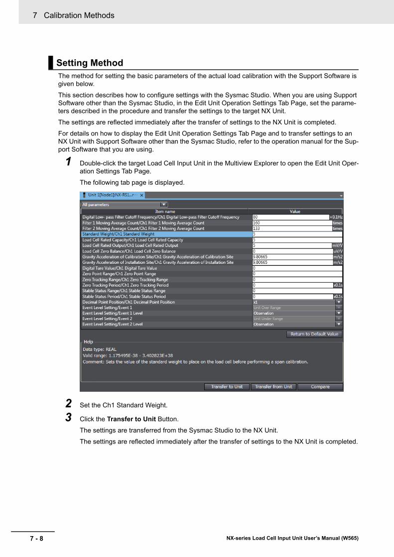
7 Calibration Methods
7 - 8 NX-series Load Cell Input Unit User’s Manual (W565)
The method for setting the basic parameters of the actual load calibration with the Support Software is given below.
This section describes how to configure settings with the Sysmac Studio. When you are using Support Software other than the Sysmac Studio, in the Edit Unit Operation Settings Tab Page, set the parame-ters described in the procedure and transfer the settings to the target NX Unit.
The settings are reflected immediately after the transfer of settings to the NX Unit is completed.
For details on how to display the Edit Unit Operation Settings Tab Page and to transfer settings to an NX Unit with Support Software other than the Sysmac Studio, refer to the operation manual for the Sup-port Software that you are using.
1 Double-click the target Load Cell Input Unit in the Multiview Explorer to open the Edit Unit Oper-ation Settings Tab Page.
The following tab page is displayed.
2 Set the Ch1 Standard Weight.
3 Click the Transfer to Unit Button.
The settings are transferred from the Sysmac Studio to the NX Unit.
The settings are reflected immediately after the transfer of settings to the NX Unit is completed.
Setting Method
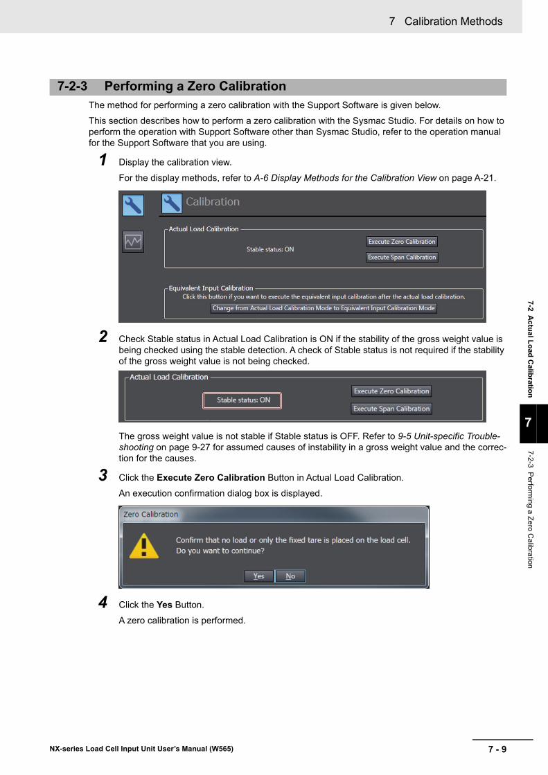
7 - 9
7 Calibration Methods
NX-series Load Cell Input Unit User’s Manual (W565)
7-2 Actu
al Lo
ad C
alibratio
n
7
7-2-3 P
erforming a Z
ero C
alibration
The method for performing a zero calibration with the Support Software is given below.
This section describes how to perform a zero calibration with the Sysmac Studio. For details on how to perform the operation with Support Software other than Sysmac Studio, refer to the operation manual for the Support Software that you are using.
1 Display the calibration view.
For the display methods, refer to A-6 Display Methods for the Calibration View on page A-21.
2 Check Stable status in Actual Load Calibration is ON if the stability of the gross weight value is being checked using the stable detection. A check of Stable status is not required if the stability of the gross weight value is not being checked.
The gross weight value is not stable if Stable status is OFF. Refer to 9-5 Unit-specific Trouble-shooting on page 9-27 for assumed causes of instability in a gross weight value and the correc-tion for the causes.
3 Click the Execute Zero Calibration Button in Actual Load Calibration.
An execution confirmation dialog box is displayed.
4 Click the Yes Button.
A zero calibration is performed.
7-2-3 Performing a Zero Calibration
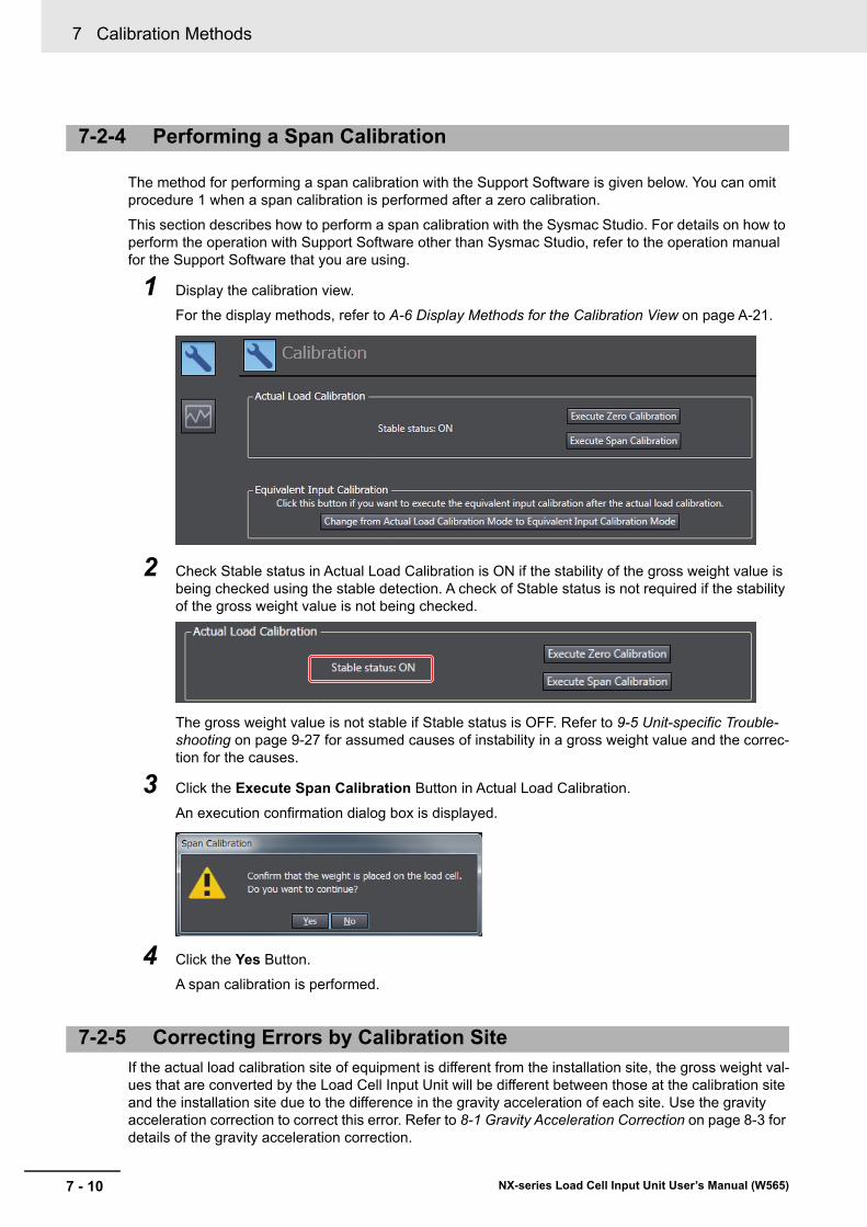
7 Calibration Methods
7 - 10 NX-series Load Cell Input Unit User’s Manual (W565)
The method for performing a span calibration with the Support Software is given below. You can omit procedure 1 when a span calibration is performed after a zero calibration.
This section describes how to perform a span calibration with the Sysmac Studio. For details on how to perform the operation with Support Software other than Sysmac Studio, refer to the operation manual for the Support Software that you are using.
1 Display the calibration view.
For the display methods, refer to A-6 Display Methods for the Calibration View on page A-21.
2 Check Stable status in Actual Load Calibration is ON if the stability of the gross weight value is being checked using the stable detection. A check of Stable status is not required if the stability of the gross weight value is not being checked.
The gross weight value is not stable if Stable status is OFF. Refer to 9-5 Unit-specific Trouble-shooting on page 9-27 for assumed causes of instability in a gross weight value and the correc-tion for the causes.
3 Click the Execute Span Calibration Button in Actual Load Calibration.
An execution confirmation dialog box is displayed.
4 Click the Yes Button.
A span calibration is performed.
If the actual load calibration site of equipment is different from the installation site, the gross weight val-ues that are converted by the Load Cell Input Unit will be different between those at the calibration site and the installation site due to the difference in the gravity acceleration of each site. Use the gravity acceleration correction to correct this error. Refer to 8-1 Gravity Acceleration Correction on page 8-3 for details of the gravity acceleration correction.
7-2-4 Performing a Span Calibration
7-2-5 Correcting Errors by Calibration Site
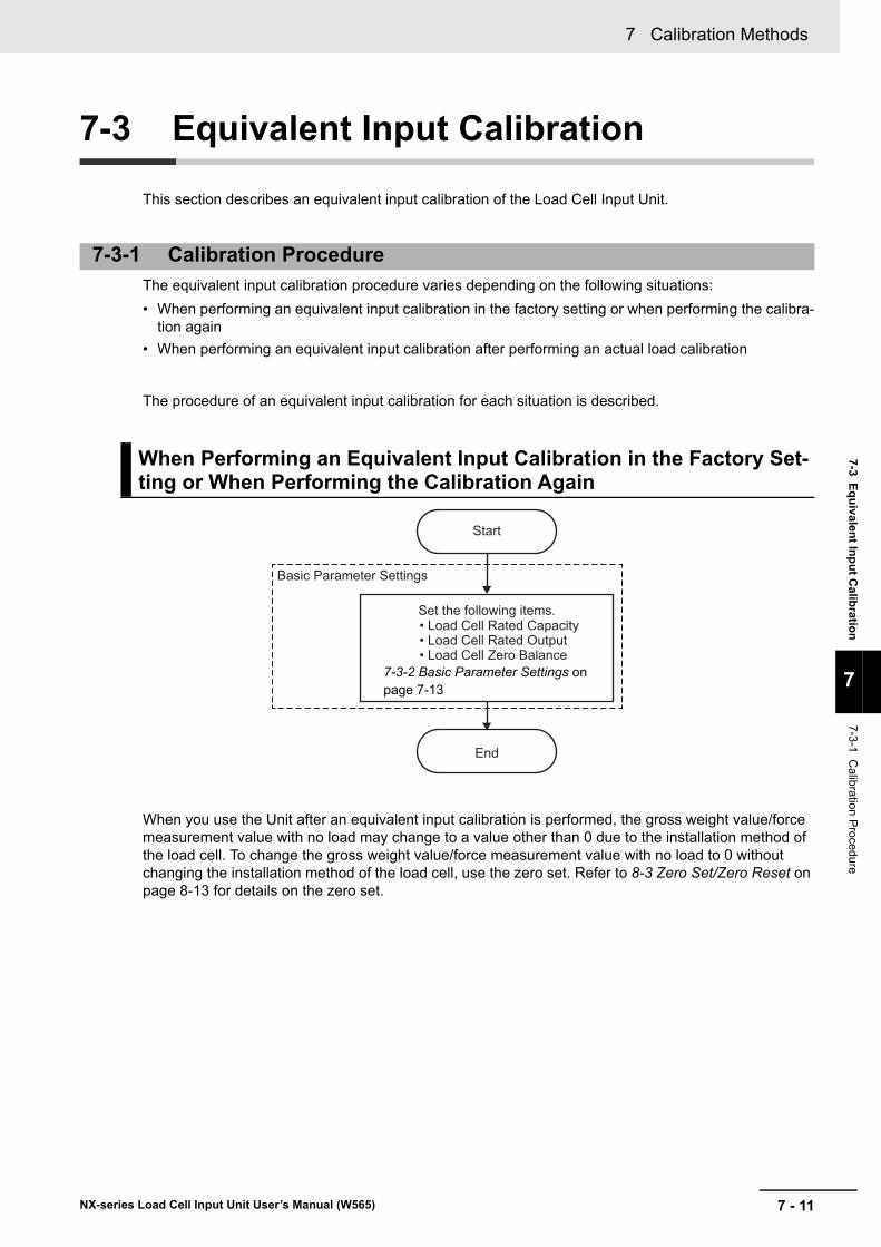
7 - 11
7 Calibration Methods
NX-series Load Cell Input Unit User’s Manual (W565)
7-3 Eq
uivalen
t Inp
ut C
alibratio
n
7
7-3-1 C
alibration Procedure
7-3 Equivalent Input Calibration
This section describes an equivalent input calibration of the Load Cell Input Unit.
The equivalent input calibration procedure varies depending on the following situations:
• When performing an equivalent input calibration in the factory setting or when performing the calibra-tion again
• When performing an equivalent input calibration after performing an actual load calibration
The procedure of an equivalent input calibration for each situation is described.
When you use the Unit after an equivalent input calibration is performed, the gross weight value/force measurement value with no load may change to a value other than 0 due to the installation method of the load cell. To change the gross weight value/force measurement value with no load to 0 without changing the installation method of the load cell, use the zero set. Refer to 8-3 Zero Set/Zero Reset on page 8-13 for details on the zero set.
7-3-1 Calibration Procedure
When Performing an Equivalent Input Calibration in the Factory Set-ting or When Performing the Calibration Again
Set the following items.
Start
End
Basic Parameter Settings
• Load Cell Rated Capacity• Load Cell Rated Output• Load Cell Zero Balance
7-3-2 Basic Parameter Settings on page 7-13
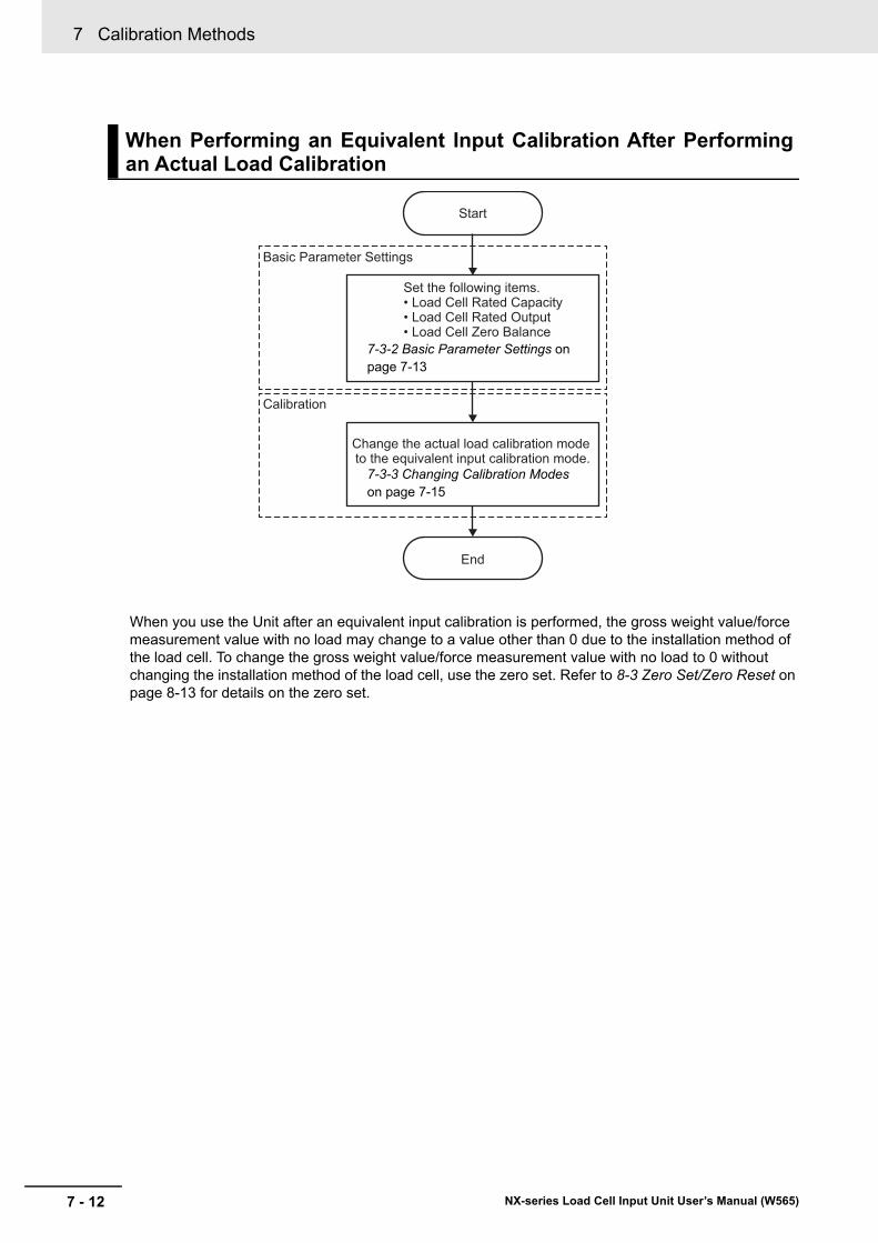
7 Calibration Methods
7 - 12 NX-series Load Cell Input Unit User’s Manual (W565)
When you use the Unit after an equivalent input calibration is performed, the gross weight value/force measurement value with no load may change to a value other than 0 due to the installation method of the load cell. To change the gross weight value/force measurement value with no load to 0 without changing the installation method of the load cell, use the zero set. Refer to 8-3 Zero Set/Zero Reset on page 8-13 for details on the zero set.
When Performing an Equivalent Input Calibration After Performingan Actual Load Calibration
Start
End
Basic Parameter Settings
Change the actual load calibration mode to the equivalent input calibration mode.
Calibration
Set the following items.• Load Cell Rated Capacity• Load Cell Rated Output• Load Cell Zero Balance
7-3-2 Basic Parameter Settings on page 7-13
7-3-3 Changing Calibration Modes on page 7-15
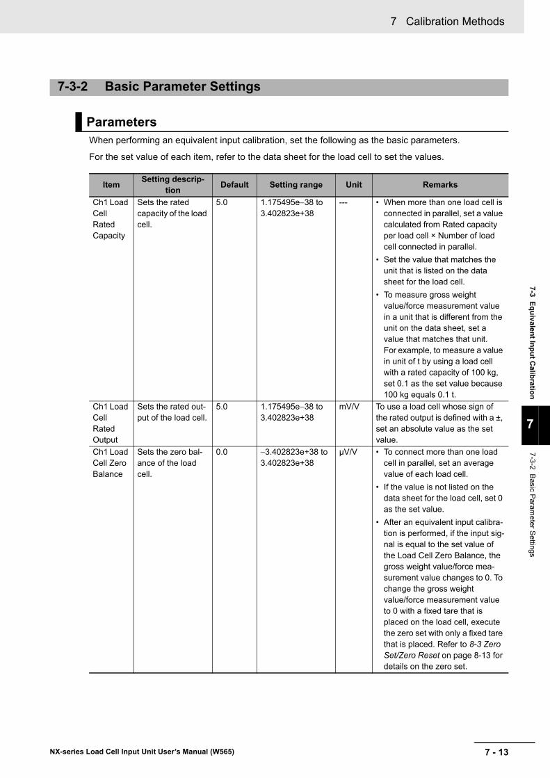
7 - 13
7 Calibration Methods
NX-series Load Cell Input Unit User’s Manual (W565)
7-3 Eq
uivalen
t Inp
ut C
alibratio
n
7
7-3-2 B
asic Param
eter Settings
When performing an equivalent input calibration, set the following as the basic parameters.
For the set value of each item, refer to the data sheet for the load cell to set the values.
7-3-2 Basic Parameter Settings
Parameters
ItemSetting descrip-
tionDefault Setting range Unit Remarks
Ch1 Load Cell Rated Capacity
Sets the rated capacity of the load cell.
5.0 1.175495e38 to 3.402823e+38
--- • When more than one load cell is connected in parallel, set a value calculated from Rated capacity per load cell × Number of load cell connected in parallel.
• Set the value that matches the unit that is listed on the data sheet for the load cell.
• To measure gross weight value/force measurement value in a unit that is different from the unit on the data sheet, set a value that matches that unit. For example, to measure a value in unit of t by using a load cell with a rated capacity of 100 kg, set 0.1 as the set value because 100 kg equals 0.1 t.
Ch1 Load Cell Rated Output
Sets the rated out-put of the load cell.
5.0 1.175495e38 to 3.402823e+38
mV/V To use a load cell whose sign of the rated output is defined with a ±, set an absolute value as the set value.
Ch1 Load Cell Zero Balance
Sets the zero bal-ance of the load cell.
0.0 3.402823e+38 to 3.402823e+38
μV/V • To connect more than one load cell in parallel, set an average value of each load cell.
• If the value is not listed on the data sheet for the load cell, set 0 as the set value.
• After an equivalent input calibra-tion is performed, if the input sig-nal is equal to the set value of the Load Cell Zero Balance, the gross weight value/force mea-surement value changes to 0. To change the gross weight value/force measurement value to 0 with a fixed tare that is placed on the load cell, execute the zero set with only a fixed tare that is placed. Refer to 8-3 Zero Set/Zero Reset on page 8-13 for details on the zero set.
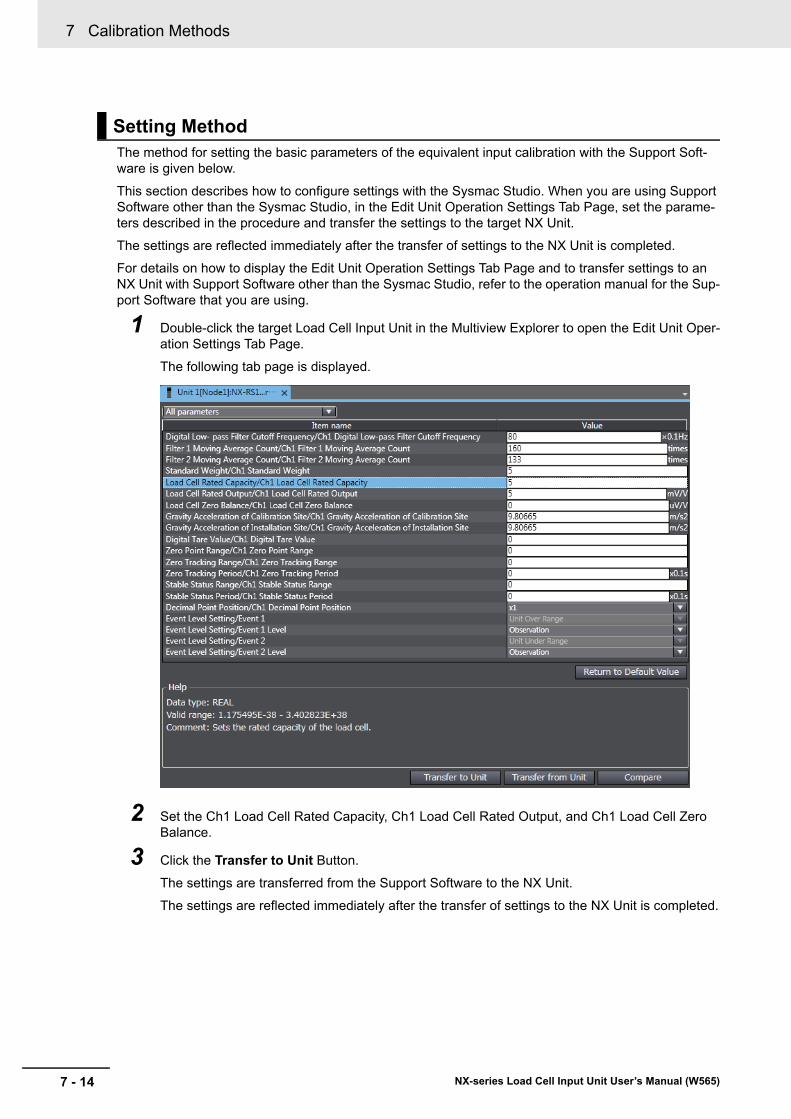
7 Calibration Methods
7 - 14 NX-series Load Cell Input Unit User’s Manual (W565)
The method for setting the basic parameters of the equivalent input calibration with the Support Soft-ware is given below.
This section describes how to configure settings with the Sysmac Studio. When you are using Support Software other than the Sysmac Studio, in the Edit Unit Operation Settings Tab Page, set the parame-ters described in the procedure and transfer the settings to the target NX Unit.
The settings are reflected immediately after the transfer of settings to the NX Unit is completed.
For details on how to display the Edit Unit Operation Settings Tab Page and to transfer settings to an NX Unit with Support Software other than the Sysmac Studio, refer to the operation manual for the Sup-port Software that you are using.
1 Double-click the target Load Cell Input Unit in the Multiview Explorer to open the Edit Unit Oper-ation Settings Tab Page.
The following tab page is displayed.
2 Set the Ch1 Load Cell Rated Capacity, Ch1 Load Cell Rated Output, and Ch1 Load Cell Zero Balance.
3 Click the Transfer to Unit Button.
The settings are transferred from the Support Software to the NX Unit.
The settings are reflected immediately after the transfer of settings to the NX Unit is completed.
Setting Method
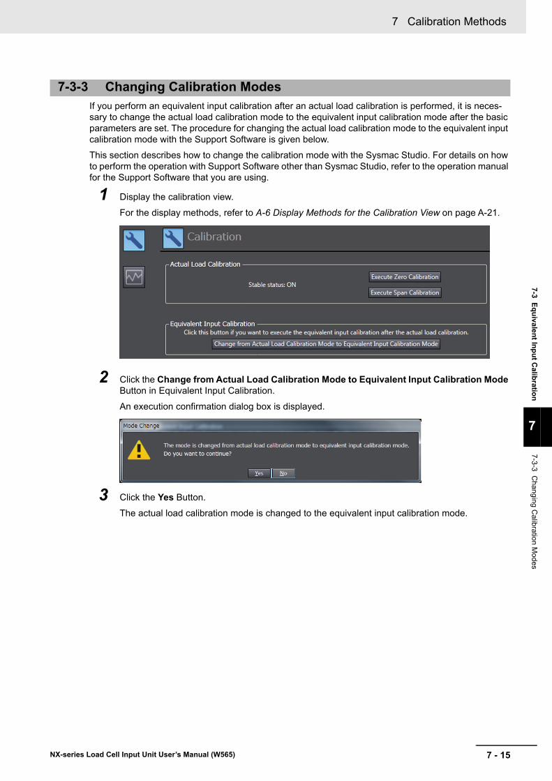
7 - 15
7 Calibration Methods
NX-series Load Cell Input Unit User’s Manual (W565)
7-3 Eq
uivalen
t Inp
ut C
alibratio
n
7
7-3-3 C
hanging
Calibration M
odes
If you perform an equivalent input calibration after an actual load calibration is performed, it is neces-sary to change the actual load calibration mode to the equivalent input calibration mode after the basic parameters are set. The procedure for changing the actual load calibration mode to the equivalent input calibration mode with the Support Software is given below.
This section describes how to change the calibration mode with the Sysmac Studio. For details on how to perform the operation with Support Software other than Sysmac Studio, refer to the operation manual for the Support Software that you are using.
1 Display the calibration view.
For the display methods, refer to A-6 Display Methods for the Calibration View on page A-21.
2 Click the Change from Actual Load Calibration Mode to Equivalent Input Calibration Mode Button in Equivalent Input Calibration.
An execution confirmation dialog box is displayed.
3 Click the Yes Button.
The actual load calibration mode is changed to the equivalent input calibration mode.
7-3-3 Changing Calibration Modes
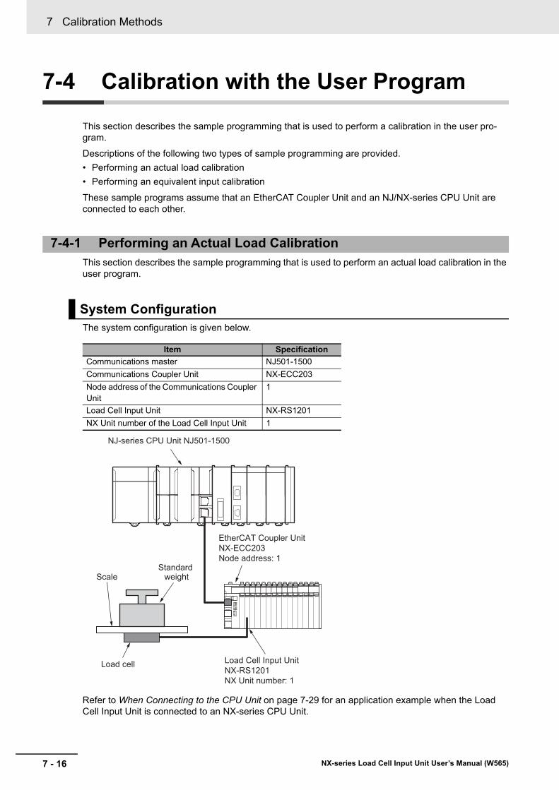
7 Calibration Methods
7 - 16 NX-series Load Cell Input Unit User’s Manual (W565)
7-4 Calibration with the User Program
This section describes the sample programming that is used to perform a calibration in the user pro-gram.
Descriptions of the following two types of sample programming are provided.
• Performing an actual load calibration
• Performing an equivalent input calibration
These sample programs assume that an EtherCAT Coupler Unit and an NJ/NX-series CPU Unit are connected to each other.
This section describes the sample programming that is used to perform an actual load calibration in the user program.
The system configuration is given below.
Refer to When Connecting to the CPU Unit on page 7-29 for an application example when the Load Cell Input Unit is connected to an NX-series CPU Unit.
7-4-1 Performing an Actual Load Calibration
System Configuration
Item Specification
Communications master NJ501-1500
Communications Coupler Unit NX-ECC203
Node address of the Communications Coupler Unit
1
Load Cell Input Unit NX-RS1201
NX Unit number of the Load Cell Input Unit 1
NJ-series CPU Unit NJ501-1500
EtherCAT Coupler UnitNX-ECC203Node address: 1
Load Cell Input UnitNX-RS1201NX Unit number: 1
Load cell
ScaleStandard
weight
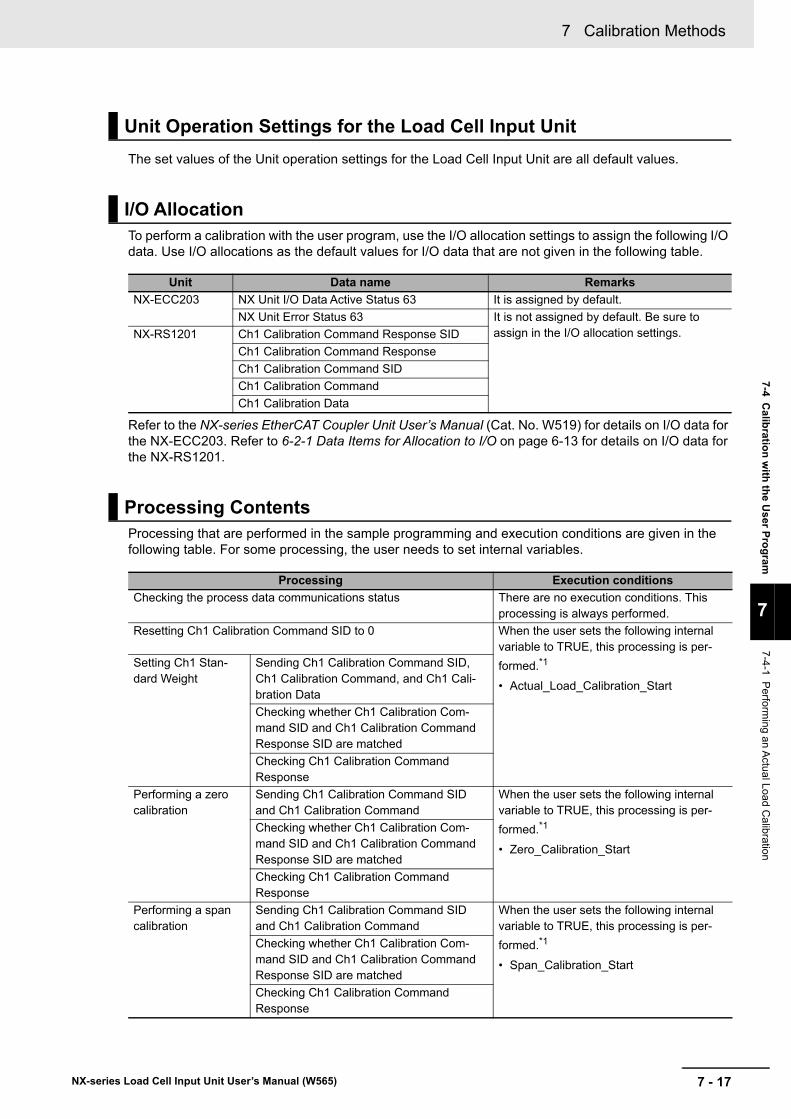
7 - 17
7 Calibration Methods
NX-series Load Cell Input Unit User’s Manual (W565)
7-4 Calib
ration
with
the U
ser Pro
gram
7
7-4-1 P
erforming an A
ctual Load
Calibration
The set values of the Unit operation settings for the Load Cell Input Unit are all default values.
To perform a calibration with the user program, use the I/O allocation settings to assign the following I/O data. Use I/O allocations as the default values for I/O data that are not given in the following table.
Refer to the NX-series EtherCAT Coupler Unit User’s Manual (Cat. No. W519) for details on I/O data for the NX-ECC203. Refer to 6-2-1 Data Items for Allocation to I/O on page 6-13 for details on I/O data for the NX-RS1201.
Processing that are performed in the sample programming and execution conditions are given in the following table. For some processing, the user needs to set internal variables.
Unit Operation Settings for the Load Cell Input Unit
I/O Allocation
Unit Data name Remarks
NX-ECC203 NX Unit I/O Data Active Status 63 It is assigned by default.
NX Unit Error Status 63 It is not assigned by default. Be sure to assign in the I/O allocation settings.NX-RS1201 Ch1 Calibration Command Response SID
Ch1 Calibration Command Response
Ch1 Calibration Command SID
Ch1 Calibration Command
Ch1 Calibration Data
Processing Contents
Processing Execution conditions
Checking the process data communications status There are no execution conditions. This processing is always performed.
Resetting Ch1 Calibration Command SID to 0 When the user sets the following internal variable to TRUE, this processing is per-
formed.*1
• Actual_Load_Calibration_Start
Setting Ch1 Stan-dard Weight
Sending Ch1 Calibration Command SID, Ch1 Calibration Command, and Ch1 Cali-bration Data
Checking whether Ch1 Calibration Com-mand SID and Ch1 Calibration Command Response SID are matched
Checking Ch1 Calibration Command Response
Performing a zero calibration
Sending Ch1 Calibration Command SID and Ch1 Calibration Command
When the user sets the following internal variable to TRUE, this processing is per-
formed.*1
• Zero_Calibration_Start
Checking whether Ch1 Calibration Com-mand SID and Ch1 Calibration Command Response SID are matched
Checking Ch1 Calibration Command Response
Performing a span calibration
Sending Ch1 Calibration Command SID and Ch1 Calibration Command
When the user sets the following internal variable to TRUE, this processing is per-
formed.*1
• Span_Calibration_Start
Checking whether Ch1 Calibration Com-mand SID and Ch1 Calibration Command Response SID are matched
Checking Ch1 Calibration Command Response
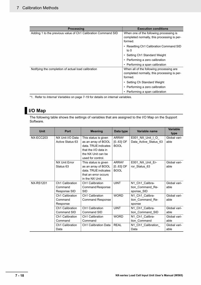
7 Calibration Methods
7 - 18 NX-series Load Cell Input Unit User’s Manual (W565)
The following table shows the settings of variables that are assigned to the I/O Map on the Support Software.
Adding 1 to the previous value of Ch1 Calibration Command SID When one of the following processing is completed normally, this processing is per-formed.
• Resetting Ch1 Calibration Command SID to 0
• Setting Ch1 Standard Weight
• Performing a zero calibration
• Performing a span calibration
Notifying the completion of actual load calibration When all of the following processing are completed normally, this processing is per-formed.
• Setting Ch Standard Weight
• Performing a zero calibration
• Performing a span calibration
*1. Refer to Internal Variables on page 7-19 for details on internal variables.
I/O Map
Unit Port Meaning Data type Variable nameVariable
type
NX-ECC203 NX Unit I/O Data Active Status 63
This status is given as an array of BOOL data. TRUE indicates that the I/O data in the NX Unit can be used for control.
ARRAY [0..63] OF BOOL
E001_NX_Unit_I_O_Data_Active_Status_63
Global vari-able
NX Unit Error Status 63
This status is given as an array of BOOL data. TRUE indicates that an error occurs in the NX Unit.
ARRAY [0..63] OF BOOL
E001_NX_Unit_Er-ror_Status_63
Global vari-able
NX-RS1201 Ch1 Calibration Command Response SID
Ch1 Calibration Command Response SID
UINT N1_Ch1_Calibra-tion_Command_Re-sponse_SID
Global vari-able
Ch1 Calibration Command Response
Ch1 Calibration Command Response
WORD N1_Ch1_Calibra-tion_Command_Re-sponse
Global vari-able
Ch1 Calibration Command SID
Ch1 Calibration Command SID
UINT N1_Ch1_Calibra-tion_Command_SID
Global vari-able
Ch1 Calibration Command
Ch1 Calibration Command
WORD N1_Ch1_Calibra-tion_Command
Global vari-able
Ch1 Calibration Data
Ch1 Calibration Data REAL N1_Ch1_Calibration_Data
Global vari-able
Processing Execution conditions
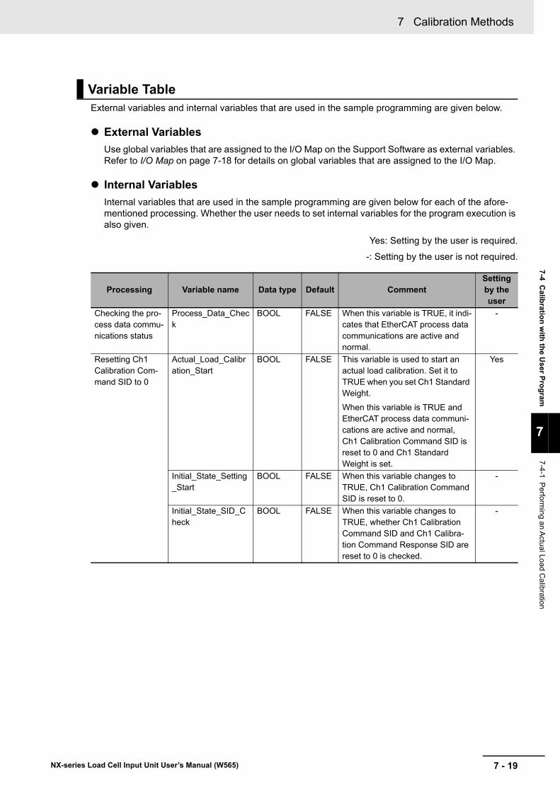
7 - 19
7 Calibration Methods
NX-series Load Cell Input Unit User’s Manual (W565)
7-4 Calib
ration
with
the U
ser Pro
gram
7
7-4-1 P
erforming an A
ctual Load
Calibration
External variables and internal variables that are used in the sample programming are given below.
External Variables
Use global variables that are assigned to the I/O Map on the Support Software as external variables. Refer to I/O Map on page 7-18 for details on global variables that are assigned to the I/O Map.
Internal Variables
Internal variables that are used in the sample programming are given below for each of the afore-mentioned processing. Whether the user needs to set internal variables for the program execution is also given.
Yes: Setting by the user is required.
-: Setting by the user is not required.
Variable Table
Processing Variable name Data type Default CommentSetting by the user
Checking the pro-cess data commu-nications status
Process_Data_Check
BOOL FALSE When this variable is TRUE, it indi-cates that EtherCAT process data communications are active and normal.
-
Resetting Ch1 Calibration Com-mand SID to 0
Actual_Load_Calibration_Start
BOOL FALSE This variable is used to start an actual load calibration. Set it to TRUE when you set Ch1 Standard Weight.
When this variable is TRUE and EtherCAT process data communi-cations are active and normal, Ch1 Calibration Command SID is reset to 0 and Ch1 Standard Weight is set.
Yes
Initial_State_Setting_Start
BOOL FALSE When this variable changes to TRUE, Ch1 Calibration Command SID is reset to 0.
-
Initial_State_SID_Check
BOOL FALSE When this variable changes to TRUE, whether Ch1 Calibration Command SID and Ch1 Calibra-tion Command Response SID are reset to 0 is checked.
-
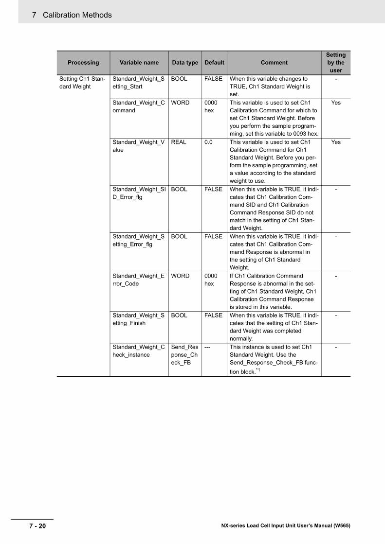
7 Calibration Methods
7 - 20 NX-series Load Cell Input Unit User’s Manual (W565)
Setting Ch1 Stan-dard Weight
Standard_Weight_Setting_Start
BOOL FALSE When this variable changes to TRUE, Ch1 Standard Weight is set.
-
Standard_Weight_Command
WORD 0000 hex
This variable is used to set Ch1 Calibration Command for which to set Ch1 Standard Weight. Before you perform the sample program-ming, set this variable to 0093 hex.
Yes
Standard_Weight_Value
REAL 0.0 This variable is used to set Ch1 Calibration Command for Ch1 Standard Weight. Before you per-form the sample programming, set a value according to the standard weight to use.
Yes
Standard_Weight_SID_Error_flg
BOOL FALSE When this variable is TRUE, it indi-cates that Ch1 Calibration Com-mand SID and Ch1 Calibration Command Response SID do not match in the setting of Ch1 Stan-dard Weight.
-
Standard_Weight_Setting_Error_flg
BOOL FALSE When this variable is TRUE, it indi-cates that Ch1 Calibration Com-mand Response is abnormal in the setting of Ch1 Standard Weight.
-
Standard_Weight_Error_Code
WORD 0000 hex
If Ch1 Calibration Command Response is abnormal in the set-ting of Ch1 Standard Weight, Ch1 Calibration Command Response is stored in this variable.
-
Standard_Weight_Setting_Finish
BOOL FALSE When this variable is TRUE, it indi-cates that the setting of Ch1 Stan-dard Weight was completed normally.
-
Standard_Weight_Check_instance
Send_Response_Check_FB
--- This instance is used to set Ch1 Standard Weight. Use the Send_Response_Check_FB func-
tion block.*1
-
Processing Variable name Data type Default CommentSetting by the user
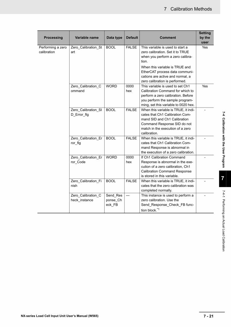
7 - 21
7 Calibration Methods
NX-series Load Cell Input Unit User’s Manual (W565)
7-4 Calib
ration
with
the U
ser Pro
gram
7
7-4-1 P
erforming an A
ctual Load
Calibration
Performing a zero calibration
Zero_Calibration_Start
BOOL FALSE This variable is used to start a zero calibration. Set it to TRUE when you perform a zero calibra-tion.
When this variable is TRUE and EtherCAT process data communi-cations are active and normal, a zero calibration is performed.
Yes
Zero_Calibration_Command
WORD 0000 hex
This variable is used to set Ch1 Calibration Command for which to perform a zero calibration. Before you perform the sample program-ming, set this variable to 0020 hex.
Yes
Zero_Calibration_SID_Error_flg
BOOL FALSE When this variable is TRUE, it indi-cates that Ch1 Calibration Com-mand SID and Ch1 Calibration Command Response SID do not match in the execution of a zero calibration.
-
Zero_Calibration_Error_flg
BOOL FALSE When this variable is TRUE, it indi-cates that Ch1 Calibration Com-mand Response is abnormal in the execution of a zero calibration.
-
Zero_Calibration_Error_Code
WORD 0000 hex
If Ch1 Calibration Command Response is abnormal in the exe-cution of a zero calibration, Ch1 Calibration Command Response is stored in this variable.
-
Zero_Calibration_Finish
BOOL FALSE When this variable is TRUE, it indi-cates that the zero calibration was completed normally.
-
Zero_Calibration_Check_instance
Send_Response_Check_FB
--- This instance is used to perform a zero calibration. Use the Send_Response_Check_FB func-
tion block.*1
-
Processing Variable name Data type Default CommentSetting by the user
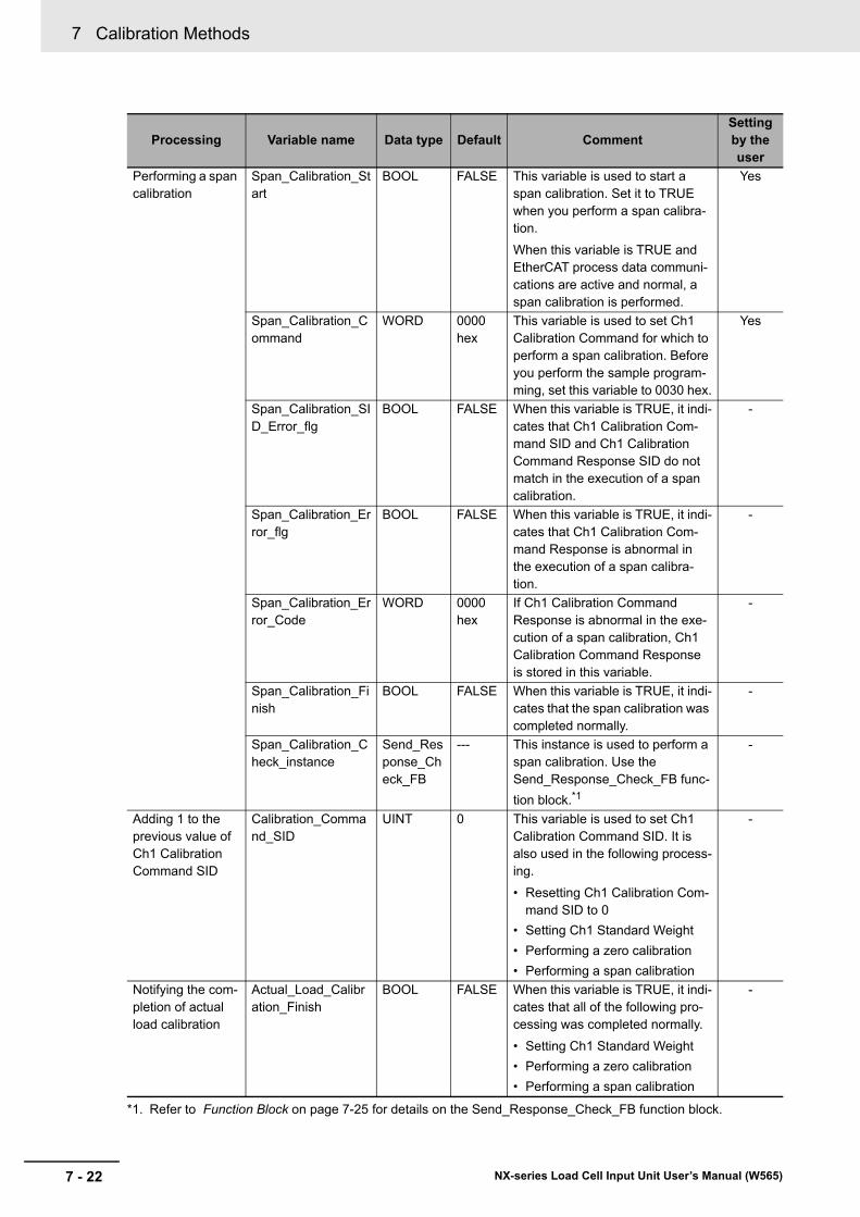
7 Calibration Methods
7 - 22 NX-series Load Cell Input Unit User’s Manual (W565)
Performing a span calibration
Span_Calibration_Start
BOOL FALSE This variable is used to start a span calibration. Set it to TRUE when you perform a span calibra-tion.
When this variable is TRUE and EtherCAT process data communi-cations are active and normal, a span calibration is performed.
Yes
Span_Calibration_Command
WORD 0000 hex
This variable is used to set Ch1 Calibration Command for which to perform a span calibration. Before you perform the sample program-ming, set this variable to 0030 hex.
Yes
Span_Calibration_SID_Error_flg
BOOL FALSE When this variable is TRUE, it indi-cates that Ch1 Calibration Com-mand SID and Ch1 Calibration Command Response SID do not match in the execution of a span calibration.
-
Span_Calibration_Error_flg
BOOL FALSE When this variable is TRUE, it indi-cates that Ch1 Calibration Com-mand Response is abnormal in the execution of a span calibra-tion.
-
Span_Calibration_Error_Code
WORD 0000 hex
If Ch1 Calibration Command Response is abnormal in the exe-cution of a span calibration, Ch1 Calibration Command Response is stored in this variable.
-
Span_Calibration_Finish
BOOL FALSE When this variable is TRUE, it indi-cates that the span calibration was completed normally.
-
Span_Calibration_Check_instance
Send_Response_Check_FB
--- This instance is used to perform a span calibration. Use the Send_Response_Check_FB func-
tion block.*1
-
Adding 1 to the previous value of Ch1 Calibration Command SID
Calibration_Command_SID
UINT 0 This variable is used to set Ch1 Calibration Command SID. It is also used in the following process-ing.
• Resetting Ch1 Calibration Com-mand SID to 0
• Setting Ch1 Standard Weight
• Performing a zero calibration
• Performing a span calibration
-
Notifying the com-pletion of actual load calibration
Actual_Load_Calibration_Finish
BOOL FALSE When this variable is TRUE, it indi-cates that all of the following pro-cessing was completed normally.
• Setting Ch1 Standard Weight
• Performing a zero calibration
• Performing a span calibration
-
*1. Refer to Function Block on page 7-25 for details on the Send_Response_Check_FB function block.
Processing Variable name Data type Default CommentSetting by the user
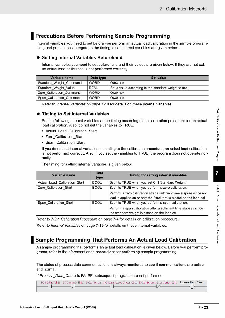
7 - 23
7 Calibration Methods
NX-series Load Cell Input Unit User’s Manual (W565)
7-4 Calib
ration
with
the U
ser Pro
gram
7
7-4-1 P
erforming an A
ctual Load
Calibration
Internal variables you need to set before you perform an actual load calibration in the sample program-ming and precautions in regard to the timing to set internal variables are given below.
Setting Internal Variables Beforehand
Internal variables you need to set beforehand and their values are given below. If they are not set, an actual load calibration is not performed correctly.
Refer to Internal Variables on page 7-19 for details on these internal variables.
Timing to Set Internal Variables
Set the following internal variables at the timing according to the calibration procedure for an actual load calibration. Also, do not set the variables to TRUE.
• Actual_Load_Calibration_Start
• Zero_Calibration_Start
• Span_Calibration_Start
If you do not set internal variables according to the calibration procedure, an actual load calibration is not performed correctly. Also, if you set the variables to TRUE, the program does not operate nor-mally.
The timing for setting internal variables is given below.
Refer to 7-2-1 Calibration Procedure on page 7-4 for details on calibration procedure.
Refer to Internal Variables on page 7-19 for details on these internal variables.
A sample programming that performs an actual load calibration is given below. Before you perform pro-grams, refer to the aforementioned precautions for performing sample programming.
The status of process data communications is always monitored to see if communications are active and normal.
If Process_Data_Check is FALSE, subsequent programs are not performed.
Precautions Before Performing Sample Programming
Variable name Data type Set value
Standard_Weight_Command WORD 0093 hex
Standard_Weight_Value REAL Set a value according to the standard weight to use.
Zero_Calibration_Command WORD 0020 hex
Span_Calibration_Command WORD 0030 hex
Variable nameData type
Timing for setting internal variables
Actual_Load_Calibration_Start BOOL Set it to TRUE when you set Ch1 Standard Weight.
Zero_Calibration_Start BOOL Set it to TRUE when you perform a zero calibration.
Perform a zero calibration after a sufficient time elapses since no load is applied on or only the fixed tare is placed on the load cell.
Span_Calibration_Start BOOL Set it to TRUE when you perform a span calibration.
Perform a span calibration after a sufficient time elapses since the standard weight is placed on the load cell.
Sample Programming That Performs An Actual Load Calibration
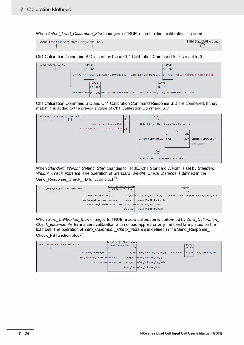
7 Calibration Methods
7 - 24 NX-series Load Cell Input Unit User’s Manual (W565)
When Actual_Load_Calibration_Start changes to TRUE, an actual load calibration is started.
Ch1 Calibration Command SID is sent by 0 and Ch1 Calibration Command SID is reset to 0.
Ch1 Calibration Command SID and Ch1 Calibration Command Response SID are compared. If they match, 1 is added to the previous value of Ch1 Calibration Command SID.
When Standard_Weight_Setting_Start changes to TRUE, Ch1 Standard Weight is set by Standard_Weight_Check_instance. The operation of Standard_Weight_Check_instance is defined in the
Send_Response_Check_FB function block*1.
When Zero_Calibration_Start changes to TRUE, a zero calibration is performed by Zero_Calibration_Check_instance. Perform a zero calibration with no load applied or only the fixed tare placed on the load cell. The operation of Zero_Calibration_Check_instance is defined in the Send_Response_
Check_FB function block*1.
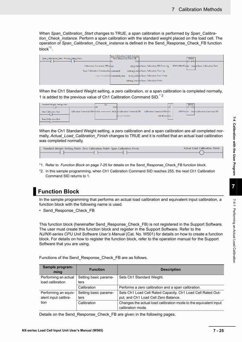
7 - 25
7 Calibration Methods
NX-series Load Cell Input Unit User’s Manual (W565)
7-4 Calib
ration
with
the U
ser Pro
gram
7
7-4-1 P
erforming an A
ctual Load
Calibration
When Span_Calibration_Start changes to TRUE, a span calibration is performed by Span_Calibra-tion_Check_instance. Perform a span calibration with the standard weight placed on the load cell. The operation of Span_Calibration_Check_instance is defined in the Send_Response_Check_FB function
block*1.
When the Ch1 Standard Weight setting, a zero calibration, or a span calibration is completed normally,
1 is added to the previous value of Ch1 Calibration Command SID.* 2
When the Ch1 Standard Weight setting, a zero calibration and a span calibration are all completed nor-mally, Actual_Load_Calibration_Finish changes to TRUE and it is notified that an actual load calibration was completed normally.
*1. Refer to Function Block on page 7-25 for details on the Send_Response_Check_FB function block.
*2. In this sample programming, when Ch1 Calibration Command SID reaches 255, the next Ch1 Calibration Command SID returns to 1.
In the sample programming that performs an actual load calibration and equivalent input calibration, a function block with the following name is used.
• Send_Response_Check_FB
This function block (hereinafter Send_Response_Check_FB) is not registered in the Support Software. The user must create this function block and register in the Support Software. Refer to the NJ/NX-series CPU Unit Software User’s Manual (Cat. No. W501) for details on how to create a function block. For details on how to register the function block, refer to the operation manual for the Support Software that you are using.
Functions of the Send_Response_Check_FB are as follows.
Details on the Send_Response_Check_FB are given in the following pages.
Function Block
Sample program-ming
Function Description
Performing an actual load calibration
Setting basic parame-ters
Sets Ch1 Standard Weight.
Calibration Performs a zero calibration and a span calibration.
Performing an equiv-alent input calibra-tion
Setting basic parame-ters
Sets Ch1 Load Cell Rated Capacity, Ch1 Load Cell Rated Out-put, and Ch1 Load Cell Zero Balance.
Calibration Changes the actual load calibration mode to the equivalent input calibration mode.
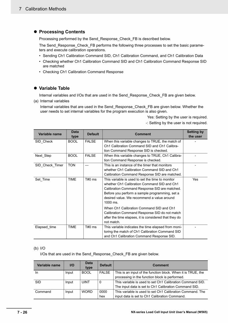
7 Calibration Methods
7 - 26 NX-series Load Cell Input Unit User’s Manual (W565)
Processing Contents
Processing performed by the Send_Response_Check_FB is described below.
The Send_Response_Check_FB performs the following three processes to set the basic parame-ters and execute calibration operations.
• Sending Ch1 Calibration Command SID, Ch1 Calibration Command, and Ch1 Calibration Data
• Checking whether Ch1 Calibration Command SID and Ch1 Calibration Command Response SID are matched
• Checking Ch1 Calibration Command Response
Variable Table
Internal variables and I/Os that are used in the Send_Response_Check_FB are given below.
(a) Internal variables
Internal variables that are used in the Send_Response_Check_FB are given below. Whether the user needs to set internal variables for the program execution is also given.
Yes: Setting by the user is required.
-: Setting by the user is not required.
(b) I/O
I/Os that are used in the Send_Response_Check_FB are given below.
Variable nameData type
Default CommentSetting by the user
SID_Check BOOL FALSE When this variable changes to TRUE, the match of Ch1 Calibration Command SID and Ch1 Calibra-tion Command Response SID is checked.
-
Next_Step BOOL FALSE When this variable changes to TRUE, Ch1 Calibra-tion Command Response is checked.
-
SID_Check_Timer TON --- This is an instance of the timer that monitors whether Ch1 Calibration Command SID and Ch1 Calibration Command Response SID are matched.
-
Set_Time TIME T#0 ms This variable is used to set the time to monitor whether Ch1 Calibration Command SID and Ch1 Calibration Command Response SID are matched. Before you perform a sample programming, set a desired value. We recommend a value around 1000 ms.
When Ch1 Calibration Command SID and Ch1 Calibration Command Response SID do not match after the time elapses, it is considered that they do not match.
Yes
Elapsed_time TIME T#0 ms This variable indicates the time elapsed from moni-toring the match of Ch1 Calibration Command SID and Ch1 Calibration Command Response SID.
-
Variable name I/OData type
Default Comment
In Input BOOL FALSE This is an input of the function block. When it is TRUE, the processing in the function block is performed.
SID Input UINT 0 This variable is used to set Ch1 Calibration Command SID. The input data is set to Ch1 Calibration Command SID.
Command Input WORD 0000 hex
This variable is used to set Ch1 Calibration Command. The input data is set to Ch1 Calibration Command.
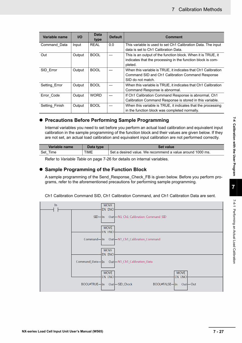
7 - 27
7 Calibration Methods
NX-series Load Cell Input Unit User’s Manual (W565)
7-4 Calib
ration
with
the U
ser Pro
gram
7
7-4-1 P
erforming an A
ctual Load
Calibration
Precautions Before Performing Sample Programming
Internal variables you need to set before you perform an actual load calibration and equivalent input calibration in the sample programming of the function block and their values are given below. If they are not set, an actual load calibration and equivalent input calibration are not performed correctly.
Refer to Variable Table on page 7-26 for details on internal variables.
Sample Programming of the Function Block
A sample programming of the Send_Response_Check_FB is given below. Before you perform pro-grams, refer to the aforementioned precautions for performing sample programming.
Ch1 Calibration Command SID, Ch1 Calibration Command, and Ch1 Calibration Data are sent.
Command_Data Input REAL 0.0 This variable is used to set Ch1 Calibration Data. The input data is set to Ch1 Calibration Data.
Out Output BOOL --- This is an output of the function block. When it is TRUE, it indicates that the processing in the function block is com-pleted.
SID_Error Output BOOL --- When this variable is TRUE, it indicates that Ch1 Calibration Command SID and Ch1 Calibration Command Response SID do not match.
Setting_Error Output BOOL --- When this variable is TRUE, it indicates that Ch1 Calibration Command Response is abnormal.
Error_Code Output WORD --- If Ch1 Calibration Command Response is abnormal, Ch1 Calibration Command Response is stored in this variable.
Setting_Finish Output BOOL --- When this variable is TRUE, it indicates that the processing in the function block was completed normally.
Variable name Data type Set value
Set_Time TIME Set a desired value. We recommend a value around 1000 ms.
Variable name I/OData type
Default Comment
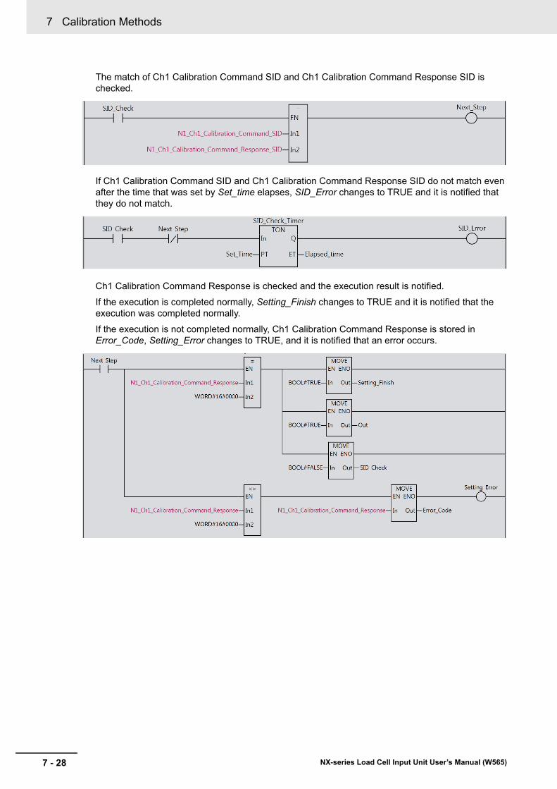
7 Calibration Methods
7 - 28 NX-series Load Cell Input Unit User’s Manual (W565)
The match of Ch1 Calibration Command SID and Ch1 Calibration Command Response SID is checked.
If Ch1 Calibration Command SID and Ch1 Calibration Command Response SID do not match even after the time that was set by Set_time elapses, SID_Error changes to TRUE and it is notified that they do not match.
Ch1 Calibration Command Response is checked and the execution result is notified.
If the execution is completed normally, Setting_Finish changes to TRUE and it is notified that the execution was completed normally.
If the execution is not completed normally, Ch1 Calibration Command Response is stored in Error_Code, Setting_Error changes to TRUE, and it is notified that an error occurs.
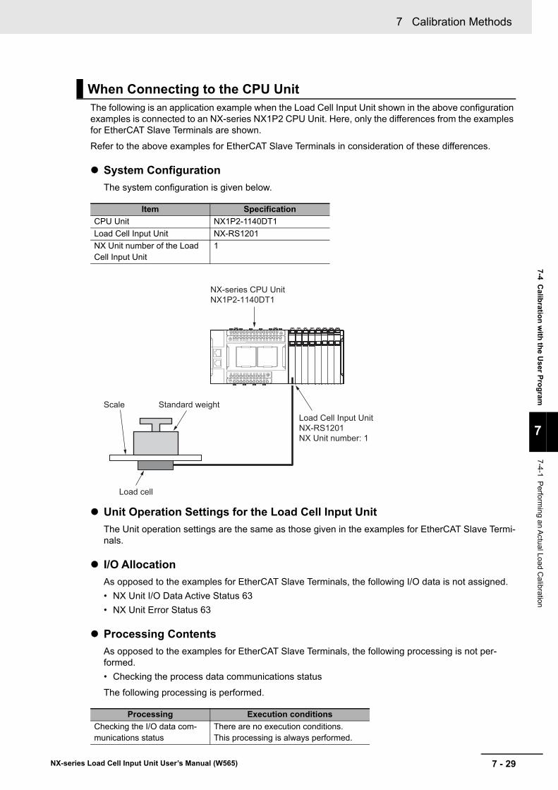
7 - 29
7 Calibration Methods
NX-series Load Cell Input Unit User’s Manual (W565)
7-4 Calib
ration
with
the U
ser Pro
gram
7
7-4-1 P
erforming an A
ctual Load
Calibration
The following is an application example when the Load Cell Input Unit shown in the above configuration examples is connected to an NX-series NX1P2 CPU Unit. Here, only the differences from the examples for EtherCAT Slave Terminals are shown.
Refer to the above examples for EtherCAT Slave Terminals in consideration of these differences.
System Configuration
The system configuration is given below.
Unit Operation Settings for the Load Cell Input Unit
The Unit operation settings are the same as those given in the examples for EtherCAT Slave Termi-nals.
I/O Allocation
As opposed to the examples for EtherCAT Slave Terminals, the following I/O data is not assigned.
• NX Unit I/O Data Active Status 63
• NX Unit Error Status 63
Processing Contents
As opposed to the examples for EtherCAT Slave Terminals, the following processing is not per-formed.
• Checking the process data communications status
The following processing is performed.
When Connecting to the CPU Unit
Item Specification
CPU Unit NX1P2-1140DT1
Load Cell Input Unit NX-RS1201
NX Unit number of the Load Cell Input Unit
1
Processing Execution conditions
Checking the I/O data com-munications status
There are no execution conditions. This processing is always performed.
Load Cell Input UnitNX-RS1201NX Unit number: 1
Load cell
Scale Standard weight
NX-series CPU UnitNX1P2-1140DT1
7 Calibration Methods
7 - 30 NX-series Load Cell Input Unit User’s Manual (W565)
I/O Map
As opposed to the examples for EtherCAT Slave Terminals, the following variables are not assigned to the I/O Map.
• E001_NX_Unit_I_O_Data_Active_Status_63
• E001_NX_Unit_Error_Status_63
You assign the following variables to the I/O Map.
Variable Table
a) External Variables
They are the same as those given in the examples for EtherCAT Slave Terminals.
b) Internal Variables
As opposed to the examples for EtherCAT Slave Terminals, the Process_Data_Check variable is not used.
The following variable is used.
Yes: Setting by the user is required.
-: Setting by the user is not required.
Unit Port MeaningData type
Variable nameVariable
type
NX-RS1201 N1 NX Unit I/O Data Active Status
TRUE indicates that the I/O data in the NX Unit can be used for control.
BOOL NXBus_N1_NX_Unit_I_O_Data_Active_Status
Global variable
N1 NX Unit Error Status
TRUE indicates that an error occurs in the NX Unit.
BOOL NXBus_N1_NX_Unit_Error_Status
Global variable
Processing Variable name Data type Default CommentSetting by the user
Checking the I/O data com-munications status
I_O_Data_Check BOOL FALSE When this variable is TRUE, it indicates that I/O data commu-nications with the NX Units are active and normal.
-
7 - 31
7 Calibration Methods
NX-series Load Cell Input Unit User’s Manual (W565)
7-4 Calib
ration
with
the U
ser Pro
gram
7
7-4-1 P
erforming an A
ctual Load
Calibration
In addition, the comments for the Actual_Load_Calibration_Start, Zero_Calibration_Start, and Span_Calibration_Start variables are replaced as follows.
Precautions Before Performing Sample Programming
They are the same as those given in the examples for EtherCAT Slave Terminals.
Sample Programming That Performs An Actual Load Calibration
Change the following inputs in the ladder diagram program for EtherCAT Slave Terminals.
In addition, replace “process data communications” in program comments with “I/O data communi-cations with the NX Units.”
Function Block
They are the same as those given in the examples for EtherCAT Slave Terminals.
Processing Variable name Data type Default CommentSetting by the user
Resetting Ch1 Calibration Command SID to 0
Actual_Load_Cali-bration_Start
BOOL FALSE This variable is used to start an actual load calibration. Set it to TRUE when you set Ch1 Standard Weight.
When this variable is TRUE and I/O data communications with the NX Units are active and normal, Ch1 Calibration Command SID is reset to 0 and Ch1 Standard Weight is set.
Yes
Performing a zero calibration
Zero_Calibra-tion_Start
BOOL FALSE This variable is used to start a zero calibration. Set it to TRUE when you perform a zero calibration.
When this variable is TRUE and I/O data communications with the NX Units are active and normal, a zero calibration is performed.
Yes
Performing a span calibra-tion
Span_Calibra-tion_Start
BOOL FALSE This variable is used to start a span calibration. Set it to TRUE when you perform a span calibration.
When this variable is TRUE and I/O data communications with the NX Units are active and normal, a span calibra-tion is performed.
Yes
Input to change Change description
_EC_PDSlavTbl[1] Delete.
_EC_CommErrTbl[1] Delete.
E001_NX_Unit_I_O_Data_Active_Status_63[1] Change to the following variable.
NXBus_N1_NX_Unit_I_O_Data_Active_Status
E001_NX_Unit_Error_Status_63[1] Change to the following variable.
NXBus_N1_NX_Unit_Error_Status
Process_Data_Check Change to the following variable.
I_O_Data_Check
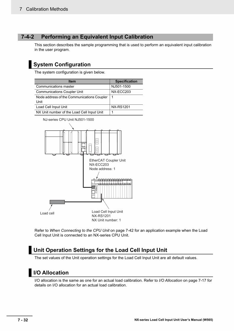
7 Calibration Methods
7 - 32 NX-series Load Cell Input Unit User’s Manual (W565)
This section describes the sample programming that is used to perform an equivalent input calibration in the user program.
The system configuration is given below.
Refer to When Connecting to the CPU Unit on page 7-42 for an application example when the Load Cell Input Unit is connected to an NX-series CPU Unit.
The set values of the Unit operation settings for the Load Cell Input Unit are all default values.
I/O allocation is the same as one for an actual load calibration. Refer to I/O Allocation on page 7-17 for details on I/O allocation for an actual load calibration.
7-4-2 Performing an Equivalent Input Calibration
System Configuration
Item Specification
Communications master NJ501-1500
Communications Coupler Unit NX-ECC203
Node address of the Communications Coupler Unit
1
Load Cell Input Unit NX-RS1201
NX Unit number of the Load Cell Input Unit 1
Unit Operation Settings for the Load Cell Input Unit
I/O Allocation
NJ-series CPU Unit NJ501-1500
EtherCAT Coupler UnitNX-ECC203Node address: 1
Load Cell Input UnitNX-RS1201NX Unit number: 1
Load cell
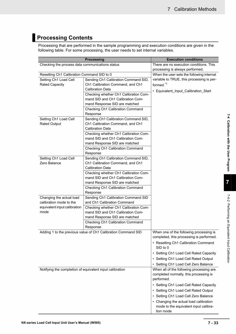
7 - 33
7 Calibration Methods
NX-series Load Cell Input Unit User’s Manual (W565)
7-4 Calib
ration
with
the U
ser Pro
gram
7
7-4-2 P
erforming an E
quivalent In
put Calibratio
n
Processing that are performed in the sample programming and execution conditions are given in the following table. For some processing, the user needs to set internal variables.
Processing Contents
Processing Execution conditions
Checking the process data communications status There are no execution conditions. This processing is always performed.
Resetting Ch1 Calibration Command SID to 0 When the user sets the following internal variable to TRUE, this processing is per-
formed.*1
• Equivalent_Input_Calibration_Start
Setting Ch1 Load Cell Rated Capacity
Sending Ch1 Calibration Command SID, Ch1 Calibration Command, and Ch1 Calibration Data
Checking whether Ch1 Calibration Com-mand SID and Ch1 Calibration Com-mand Response SID are matched
Checking Ch1 Calibration Command Response
Setting Ch1 Load Cell Rated Output
Sending Ch1 Calibration Command SID, Ch1 Calibration Command, and Ch1 Calibration Data
Checking whether Ch1 Calibration Com-mand SID and Ch1 Calibration Com-mand Response SID are matched
Checking Ch1 Calibration Command Response
Setting Ch1 Load Cell Zero Balance
Sending Ch1 Calibration Command SID, Ch1 Calibration Command, and Ch1 Calibration Data
Checking whether Ch1 Calibration Com-mand SID and Ch1 Calibration Com-mand Response SID are matched
Checking Ch1 Calibration Command Response
Changing the actual load calibration mode to the equivalent input calibration mode
Sending Ch1 Calibration Command SID and Ch1 Calibration Command
Checking whether Ch1 Calibration Com-mand SID and Ch1 Calibration Com-mand Response SID are matched
Checking Ch1 Calibration Command Response
Adding 1 to the previous value of Ch1 Calibration Command SID When one of the following processing is completed, this processing is performed.
• Resetting Ch1 Calibration Command SID to 0
• Setting Ch1 Load Cell Rated Capacity
• Setting Ch1 Load Cell Rated Output
• Setting Ch1 Load Cell Zero Balance
Notifying the completion of equivalent input calibration When all of the following processing are completed normally, this processing is performed.
• Setting Ch1 Load Cell Rated Capacity
• Setting Ch1 Load Cell Rated Output
• Setting Ch1 Load Cell Zero Balance
• Changing the actual load calibration mode to the equivalent input calibra-tion mode
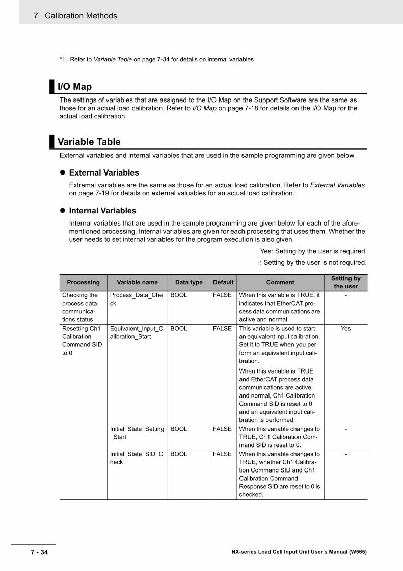
7 Calibration Methods
7 - 34 NX-series Load Cell Input Unit User’s Manual (W565)
The settings of variables that are assigned to the I/O Map on the Support Software are the same as those for an actual load calibration. Refer to I/O Map on page 7-18 for details on the I/O Map for the actual load calibration.
External variables and internal variables that are used in the sample programming are given below.
External Variables
Extremal variables are the same as those for an actual load calibration. Refer to External Variables on page 7-19 for details on external valuables for an actual load calibration.
Internal Variables
Internal variables that are used in the sample programming are given below for each of the afore-mentioned processing. Internal variables are given for each processing that uses them. Whether the user needs to set internal variables for the program execution is also given.
Yes: Setting by the user is required.
-: Setting by the user is not required.
*1. Refer to Variable Table on page 7-34 for details on internal variables.
I/O Map
Variable Table
Processing Variable name Data type Default CommentSetting by the user
Checking the process data communica-tions status
Process_Data_Check
BOOL FALSE When this variable is TRUE, it indicates that EtherCAT pro-cess data communications are active and normal.
-
Resetting Ch1 Calibration Command SID to 0
Equivalent_Input_Calibration_Start
BOOL FALSE This variable is used to start an equivalent input calibration. Set it to TRUE when you per-form an equivalent input cali-bration.
When this variable is TRUE and EtherCAT process data communications are active and normal, Ch1 Calibration Command SID is reset to 0 and an equivalent input cali-bration is performed.
Yes
Initial_State_Setting_Start
BOOL FALSE When this variable changes to TRUE, Ch1 Calibration Com-mand SID is reset to 0.
-
Initial_State_SID_Check
BOOL FALSE When this variable changes to TRUE, whether Ch1 Calibra-tion Command SID and Ch1 Calibration Command Response SID are reset to 0 is checked.
-
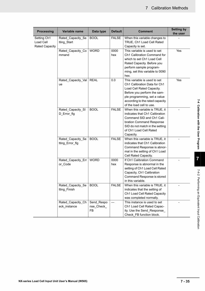
7 - 35
7 Calibration Methods
NX-series Load Cell Input Unit User’s Manual (W565)
7-4 Calib
ration
with
the U
ser Pro
gram
7
7-4-2 P
erforming an E
quivalent In
put Calibratio
n
Setting Ch1 Load Cell Rated Capacity
Rated_Capacity_Setting_Start
BOOL FALSE When this variable changes to TRUE, Ch1 Load Cell Rated Capacity is set.
-
Rated_Capacity_Command
WORD 0000 hex
This variable is used to set Ch1 Calibration Command for which to set Ch1 Load Cell Rated Capacity. Before you perform sample program-ming, set this variable to 0090 hex.
Yes
Rated_Capacity_Value
REAL 0.0 This variable is used to set Ch1 Calibration Data for Ch1 Load Cell Rated Capacity. Before you perform the sam-ple programming, set a value according to the rated capacity of the load cell to use.
Yes
Rated_Capacity_SID_Error_flg
BOOL FALSE When this variable is TRUE, it indicates that Ch1 Calibration Command SID and Ch1 Cali-bration Command Response SID do not match in the setting of Ch1 Load Cell Rated Capacity.
-
Rated_Capacity_Setting_Error_flg
BOOL FALSE When this variable is TRUE, it indicates that Ch1 Calibration Command Response is abnor-mal in the setting of Ch1 Load Cell Rated Capacity.
-
Rated_Capacity_Error_Code
WORD 0000 hex
If Ch1 Calibration Command Response is abnormal in the setting of Ch1 Load Cell Rated Capacity, Ch1 Calibration Command Response is stored in this variable.
-
Rated_Capacity_Setting_Finish
BOOL FALSE When this variable is TRUE, it indicates that the setting of Ch1 Load Cell Rated Capacity was completed normally.
-
Rated_Capacity_Check_instance
Send_Response_Check_FB
--- This instance is used to set Ch1 Load Cell Rated Capac-ity. Use the Send_Response_Check_FB function block.
-
Processing Variable name Data type Default CommentSetting by the user
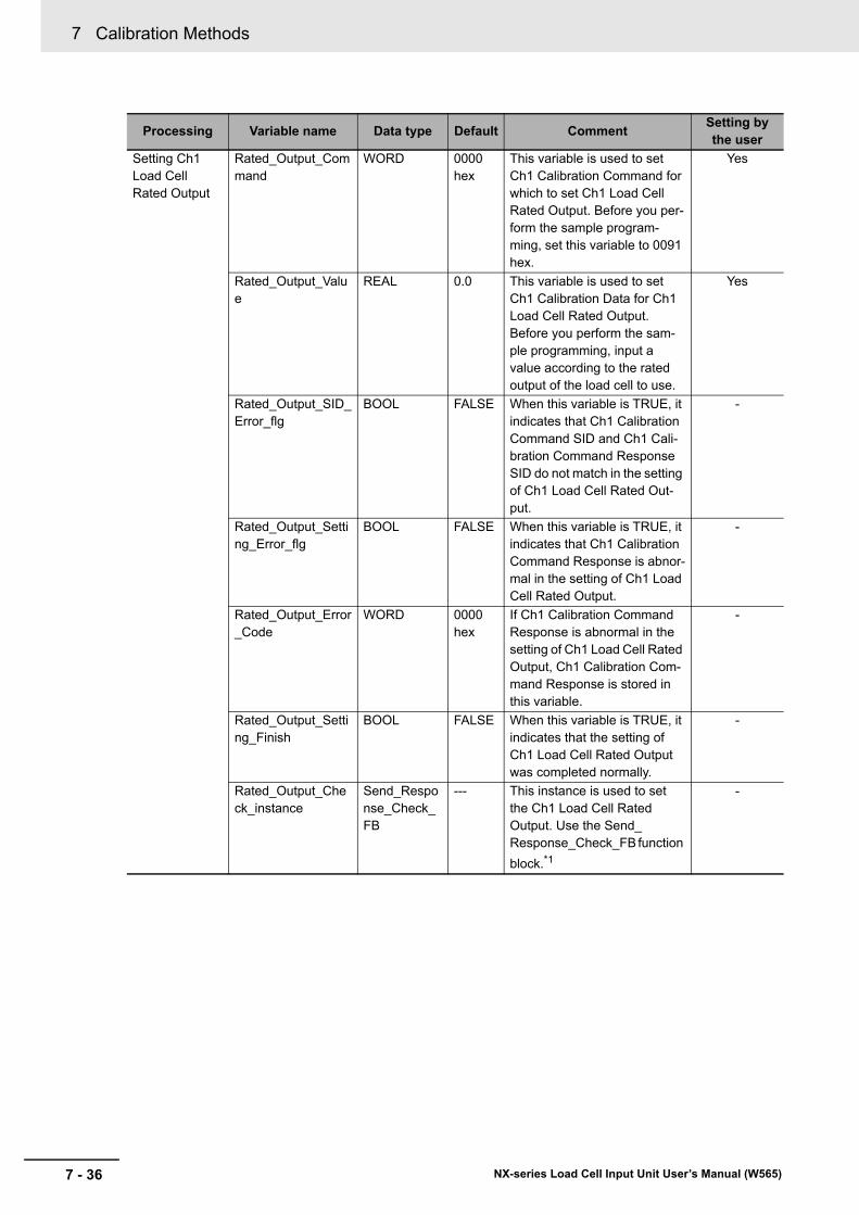
7 Calibration Methods
7 - 36 NX-series Load Cell Input Unit User’s Manual (W565)
Setting Ch1 Load Cell Rated Output
Rated_Output_Command
WORD 0000 hex
This variable is used to set Ch1 Calibration Command for which to set Ch1 Load Cell Rated Output. Before you per-form the sample program-ming, set this variable to 0091 hex.
Yes
Rated_Output_Value
REAL 0.0 This variable is used to set Ch1 Calibration Data for Ch1 Load Cell Rated Output. Before you perform the sam-ple programming, input a value according to the rated output of the load cell to use.
Yes
Rated_Output_SID_Error_flg
BOOL FALSE When this variable is TRUE, it indicates that Ch1 Calibration Command SID and Ch1 Cali-bration Command Response SID do not match in the setting of Ch1 Load Cell Rated Out-put.
-
Rated_Output_Setting_Error_flg
BOOL FALSE When this variable is TRUE, it indicates that Ch1 Calibration Command Response is abnor-mal in the setting of Ch1 Load Cell Rated Output.
-
Rated_Output_Error_Code
WORD 0000 hex
If Ch1 Calibration Command Response is abnormal in the setting of Ch1 Load Cell Rated Output, Ch1 Calibration Com-mand Response is stored in this variable.
-
Rated_Output_Setting_Finish
BOOL FALSE When this variable is TRUE, it indicates that the setting of Ch1 Load Cell Rated Output was completed normally.
-
Rated_Output_Check_instance
Send_Response_Check_FB
--- This instance is used to set the Ch1 Load Cell Rated Output. Use the Send_Response_Check_FB function
block.*1
-
Processing Variable name Data type Default CommentSetting by the user
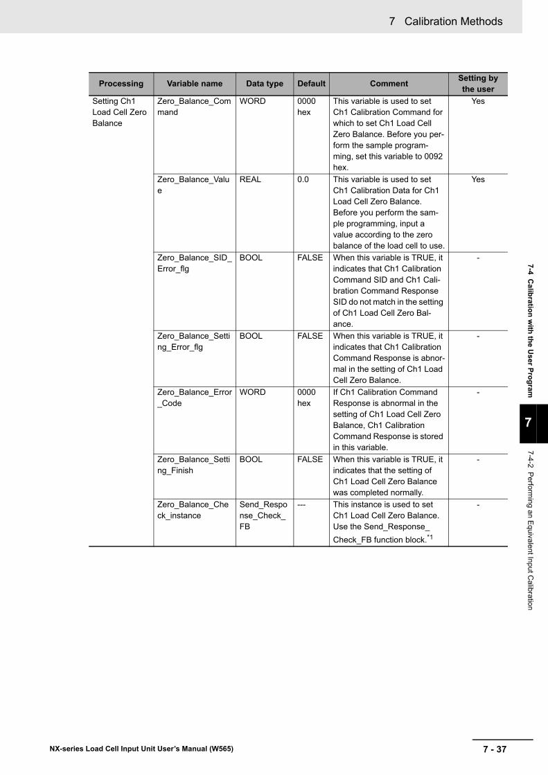
7 - 37
7 Calibration Methods
NX-series Load Cell Input Unit User’s Manual (W565)
7-4 Calib
ration
with
the U
ser Pro
gram
7
7-4-2 P
erforming an E
quivalent In
put Calibratio
n
Setting Ch1 Load Cell Zero Balance
Zero_Balance_Command
WORD 0000 hex
This variable is used to set Ch1 Calibration Command for which to set Ch1 Load Cell Zero Balance. Before you per-form the sample program-ming, set this variable to 0092 hex.
Yes
Zero_Balance_Value
REAL 0.0 This variable is used to set Ch1 Calibration Data for Ch1 Load Cell Zero Balance. Before you perform the sam-ple programming, input a value according to the zero balance of the load cell to use.
Yes
Zero_Balance_SID_Error_flg
BOOL FALSE When this variable is TRUE, it indicates that Ch1 Calibration Command SID and Ch1 Cali-bration Command Response SID do not match in the setting of Ch1 Load Cell Zero Bal-ance.
-
Zero_Balance_Setting_Error_flg
BOOL FALSE When this variable is TRUE, it indicates that Ch1 Calibration Command Response is abnor-mal in the setting of Ch1 Load Cell Zero Balance.
-
Zero_Balance_Error_Code
WORD 0000 hex
If Ch1 Calibration Command Response is abnormal in the setting of Ch1 Load Cell Zero Balance, Ch1 Calibration Command Response is stored in this variable.
-
Zero_Balance_Setting_Finish
BOOL FALSE When this variable is TRUE, it indicates that the setting of Ch1 Load Cell Zero Balance was completed normally.
-
Zero_Balance_Check_instance
Send_Response_Check_FB
--- This instance is used to set Ch1 Load Cell Zero Balance. Use the Send_Response_
Check_FB function block.*1
-
Processing Variable name Data type Default CommentSetting by the user
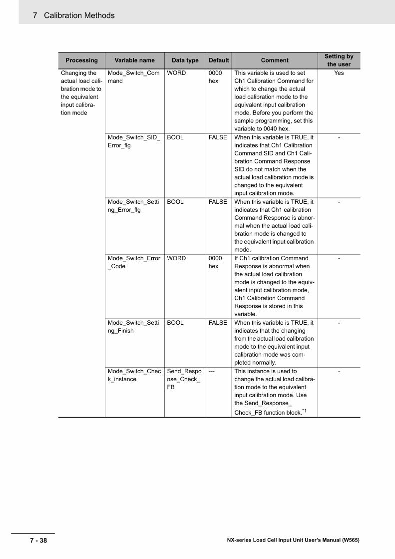
7 Calibration Methods
7 - 38 NX-series Load Cell Input Unit User’s Manual (W565)
Changing the actual load cali-bration mode to the equivalent input calibra-tion mode
Mode_Switch_Command
WORD 0000 hex
This variable is used to set Ch1 Calibration Command for which to change the actual load calibration mode to the equivalent input calibration mode. Before you perform the sample programming, set this variable to 0040 hex.
Yes
Mode_Switch_SID_Error_flg
BOOL FALSE When this variable is TRUE, it indicates that Ch1 Calibration Command SID and Ch1 Cali-bration Command Response SID do not match when the actual load calibration mode is changed to the equivalent input calibration mode.
-
Mode_Switch_Setting_Error_flg
BOOL FALSE When this variable is TRUE, it indicates that Ch1 calibration Command Response is abnor-mal when the actual load cali-bration mode is changed to the equivalent input calibration mode.
-
Mode_Switch_Error_Code
WORD 0000 hex
If Ch1 calibration Command Response is abnormal when the actual load calibration mode is changed to the equiv-alent input calibration mode, Ch1 Calibration Command Response is stored in this variable.
-
Mode_Switch_Setting_Finish
BOOL FALSE When this variable is TRUE, it indicates that the changing from the actual load calibration mode to the equivalent input calibration mode was com-pleted normally.
-
Mode_Switch_Check_instance
Send_Response_Check_FB
--- This instance is used to change the actual load calibra-tion mode to the equivalent input calibration mode. Use the Send_Response_
Check_FB function block.*1
-
Processing Variable name Data type Default CommentSetting by the user
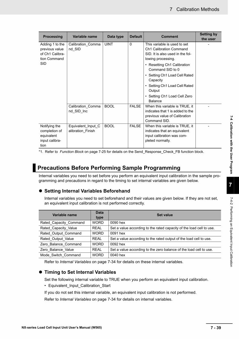
7 - 39
7 Calibration Methods
NX-series Load Cell Input Unit User’s Manual (W565)
7-4 Calib
ration
with
the U
ser Pro
gram
7
7-4-2 P
erforming an E
quivalent In
put Calibratio
n
Internal variables you need to set before you perform an equivalent input calibration in the sample pro-gramming and precautions in regard to the timing to set internal variables are given below.
Setting Internal Variables Beforehand
Internal variables you need to set beforehand and their values are given below. If they are not set, an equivalent input calibration is not performed correctly.
Refer to Internal Variables on page 7-34 for details on these internal variables.
Timing to Set Internal Variables
Set the following internal variable to TRUE when you perform an equivalent input calibration.
• Equivalent_Input_Calibration_Start
If you do not set this internal variable, an equivalent input calibration is not performed.
Refer to Internal Variables on page 7-34 for details on internal variables.
Adding 1 to the previous value of Ch1 Calibra-tion Command SID
Calibration_Command_SID
UINT 0 This variable is used to set Ch1 Calibration Command SID. It is also used in the fol-lowing processing.
• Resetting Ch1 Calibration Command SID to 0
• Setting Ch1 Load Cell Rated Capacity
• Setting Ch1 Load Cell Rated Output
• Setting Ch1 Load Cell Zero Balance
-
Calibration_Command_SID_Inc
BOOL FALSE When this variable is TRUE, it indicates that 1 is added to the previous value of Calibration Command SID.
-
Notifying the completion of equivalent input calibra-tion
Equivalent_Input_Calibration_Finish
BOOL FALSE When this variable is TRUE, it indicates that an equivalent input calibration was com-pleted normally.
-
*1. Refer to Function Block on page 7-25 for details on the Send_Response_Check_FB function block.
Precautions Before Performing Sample Programming
Variable nameData type
Set value
Rated_Capacity_Command WORD 0090 hex
Rated_Capacity_Value REAL Set a value according to the rated capacity of the load cell to use.
Rated_Output_Command WORD 0091 hex
Rated_Output_Value REAL Set a value according to the rated output of the load cell to use.
Zero_Balance_Command WORD 0092 hex
Zero_Balance_Value REAL Set a value according to the zero balance of the load cell to use.
Mode_Switch_Command WORD 0040 hex
Processing Variable name Data type Default CommentSetting by the user
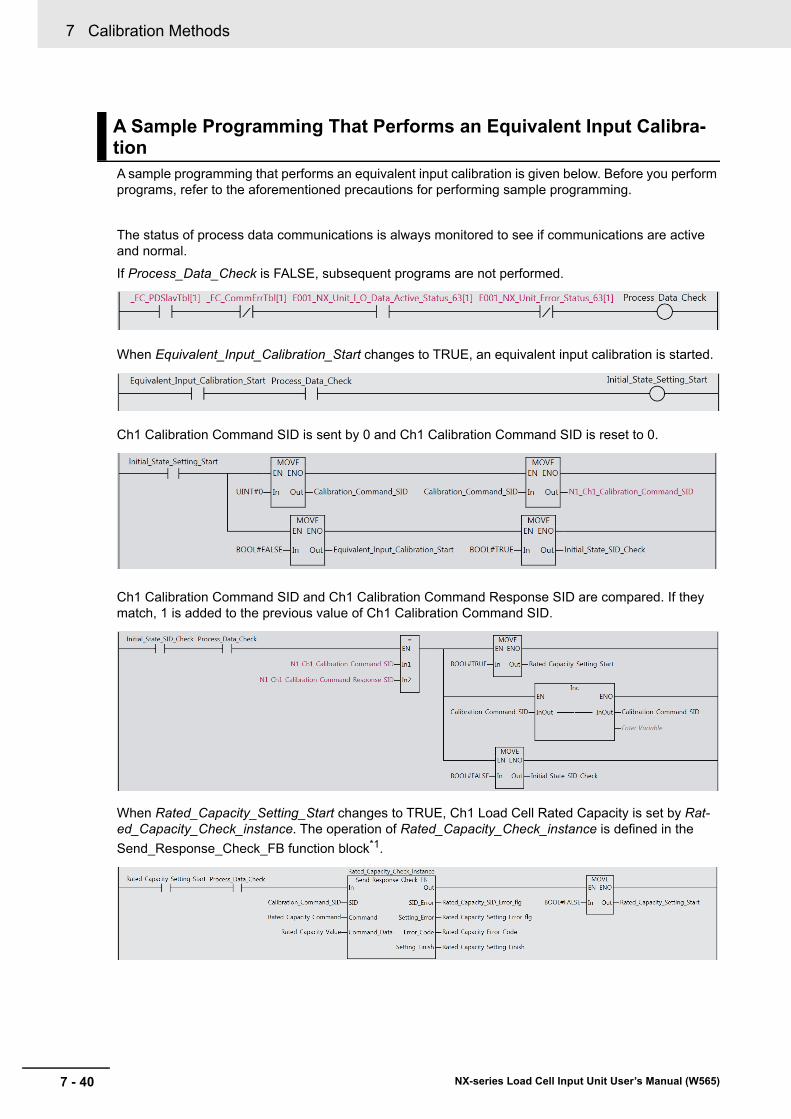
7 Calibration Methods
7 - 40 NX-series Load Cell Input Unit User’s Manual (W565)
A sample programming that performs an equivalent input calibration is given below. Before you perform programs, refer to the aforementioned precautions for performing sample programming.
The status of process data communications is always monitored to see if communications are active and normal.
If Process_Data_Check is FALSE, subsequent programs are not performed.
When Equivalent_Input_Calibration_Start changes to TRUE, an equivalent input calibration is started.
Ch1 Calibration Command SID is sent by 0 and Ch1 Calibration Command SID is reset to 0.
Ch1 Calibration Command SID and Ch1 Calibration Command Response SID are compared. If they match, 1 is added to the previous value of Ch1 Calibration Command SID.
When Rated_Capacity_Setting_Start changes to TRUE, Ch1 Load Cell Rated Capacity is set by Rat-ed_Capacity_Check_instance. The operation of Rated_Capacity_Check_instance is defined in the
Send_Response_Check_FB function block*1.
A Sample Programming That Performs an Equivalent Input Calibra-tion
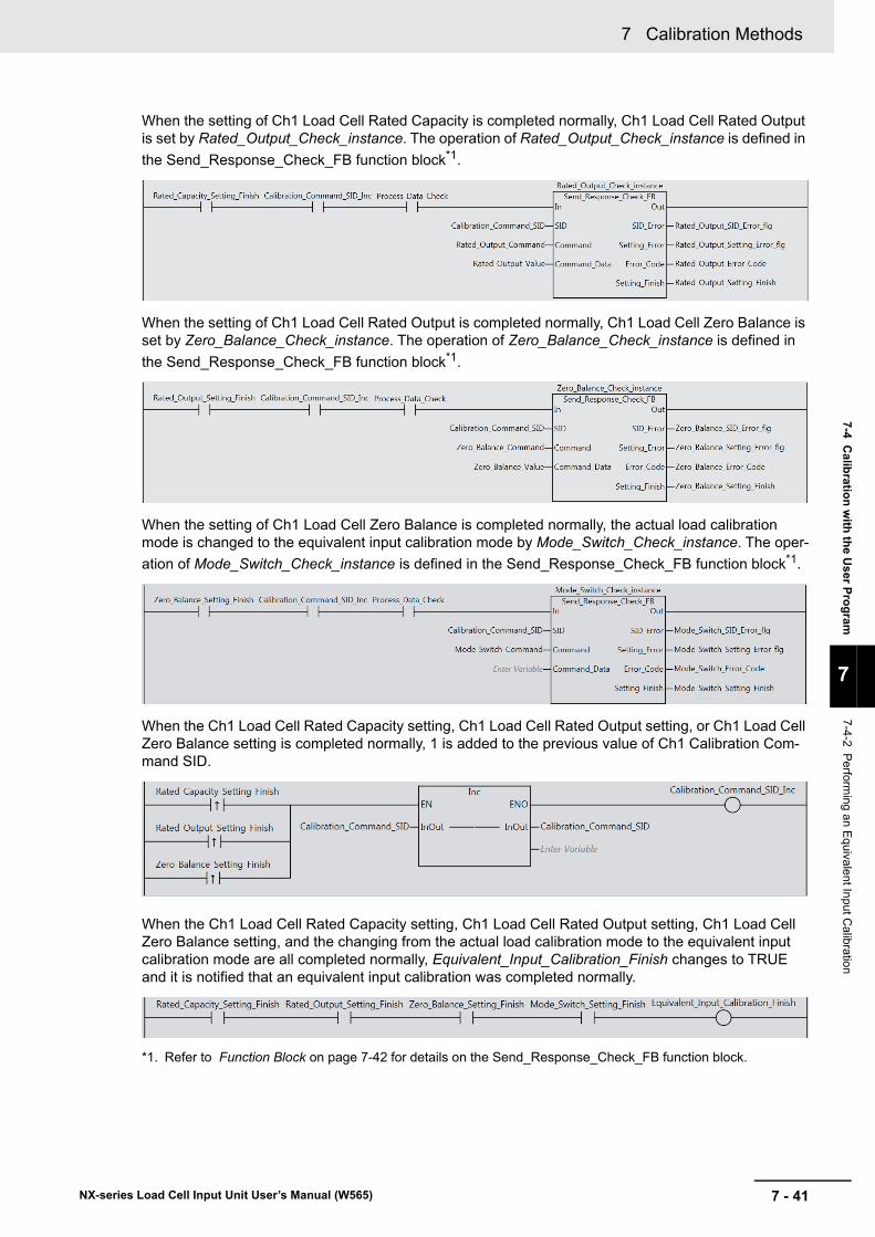
7 - 41
7 Calibration Methods
NX-series Load Cell Input Unit User’s Manual (W565)
7-4 Calib
ration
with
the U
ser Pro
gram
7
7-4-2 P
erforming an E
quivalent In
put Calibratio
n
When the setting of Ch1 Load Cell Rated Capacity is completed normally, Ch1 Load Cell Rated Output is set by Rated_Output_Check_instance. The operation of Rated_Output_Check_instance is defined in
the Send_Response_Check_FB function block*1.
When the setting of Ch1 Load Cell Rated Output is completed normally, Ch1 Load Cell Zero Balance is set by Zero_Balance_Check_instance. The operation of Zero_Balance_Check_instance is defined in
the Send_Response_Check_FB function block*1.
When the setting of Ch1 Load Cell Zero Balance is completed normally, the actual load calibration mode is changed to the equivalent input calibration mode by Mode_Switch_Check_instance. The oper-
ation of Mode_Switch_Check_instance is defined in the Send_Response_Check_FB function block*1.
When the Ch1 Load Cell Rated Capacity setting, Ch1 Load Cell Rated Output setting, or Ch1 Load Cell Zero Balance setting is completed normally, 1 is added to the previous value of Ch1 Calibration Com-mand SID.
When the Ch1 Load Cell Rated Capacity setting, Ch1 Load Cell Rated Output setting, Ch1 Load Cell Zero Balance setting, and the changing from the actual load calibration mode to the equivalent input calibration mode are all completed normally, Equivalent_Input_Calibration_Finish changes to TRUE and it is notified that an equivalent input calibration was completed normally.
*1. Refer to Function Block on page 7-42 for details on the Send_Response_Check_FB function block.
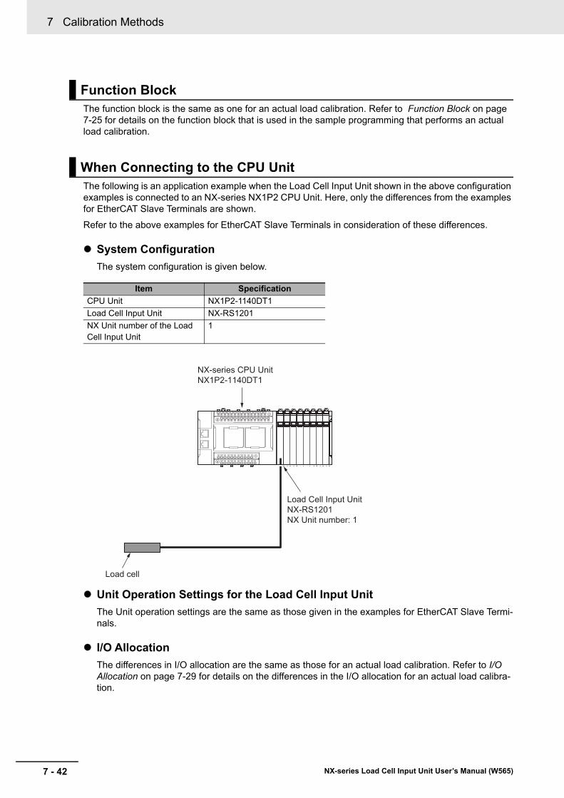
7 Calibration Methods
7 - 42 NX-series Load Cell Input Unit User’s Manual (W565)
The function block is the same as one for an actual load calibration. Refer to Function Block on page 7-25 for details on the function block that is used in the sample programming that performs an actual load calibration.
The following is an application example when the Load Cell Input Unit shown in the above configuration examples is connected to an NX-series NX1P2 CPU Unit. Here, only the differences from the examples for EtherCAT Slave Terminals are shown.
Refer to the above examples for EtherCAT Slave Terminals in consideration of these differences.
System Configuration
The system configuration is given below.
Unit Operation Settings for the Load Cell Input Unit
The Unit operation settings are the same as those given in the examples for EtherCAT Slave Termi-nals.
I/O Allocation
The differences in I/O allocation are the same as those for an actual load calibration. Refer to I/O Allocation on page 7-29 for details on the differences in the I/O allocation for an actual load calibra-tion.
Function Block
When Connecting to the CPU Unit
Item Specification
CPU Unit NX1P2-1140DT1
Load Cell Input Unit NX-RS1201
NX Unit number of the Load Cell Input Unit
1
Load Cell Input UnitNX-RS1201NX Unit number: 1
Load cell
NX-series CPU UnitNX1P2-1140DT1
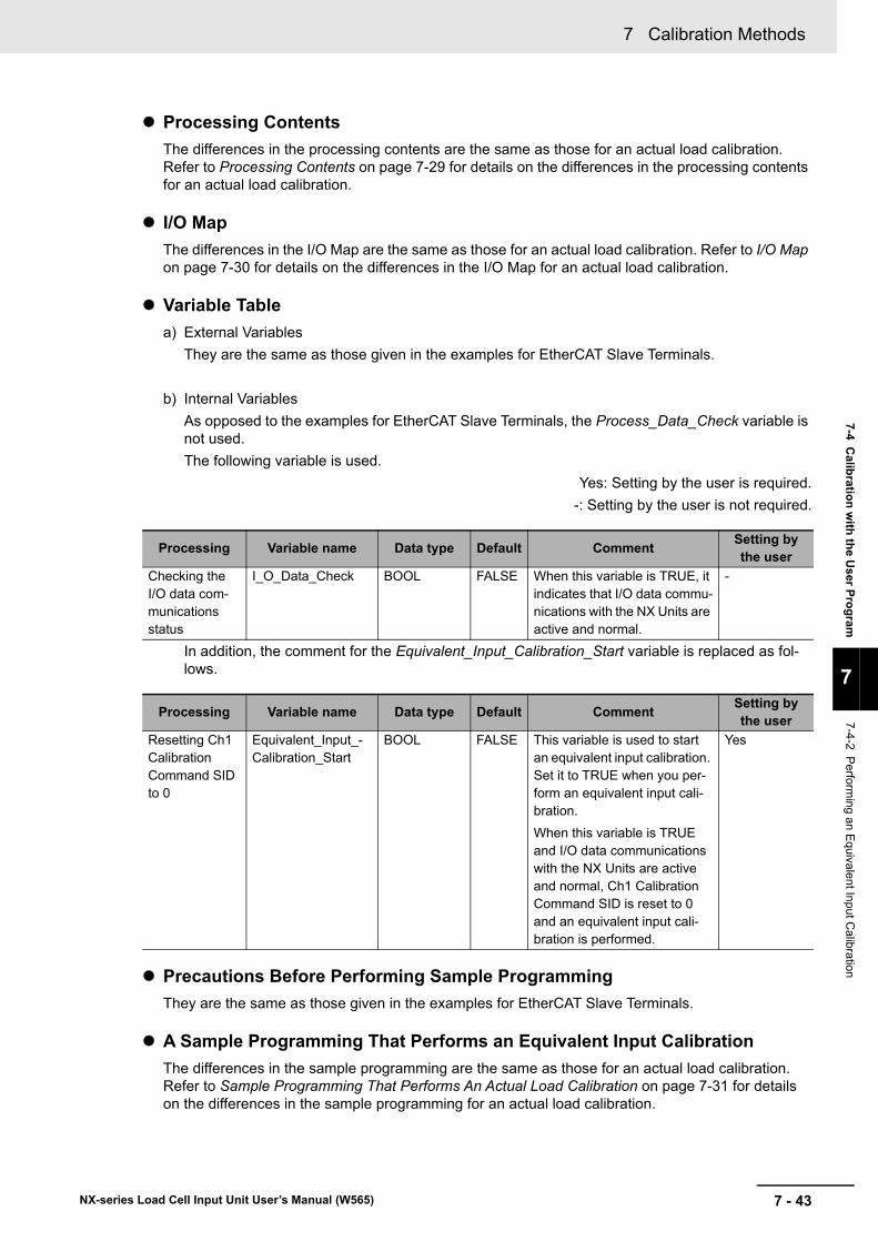
7 - 43
7 Calibration Methods
NX-series Load Cell Input Unit User’s Manual (W565)
7-4 Calib
ration
with
the U
ser Pro
gram
7
7-4-2 P
erforming an E
quivalent In
put Calibratio
n
Processing Contents
The differences in the processing contents are the same as those for an actual load calibration. Refer to Processing Contents on page 7-29 for details on the differences in the processing contents for an actual load calibration.
I/O Map
The differences in the I/O Map are the same as those for an actual load calibration. Refer to I/O Map on page 7-30 for details on the differences in the I/O Map for an actual load calibration.
Variable Table
a) External Variables
They are the same as those given in the examples for EtherCAT Slave Terminals.
b) Internal Variables
As opposed to the examples for EtherCAT Slave Terminals, the Process_Data_Check variable is not used.
The following variable is used.
Yes: Setting by the user is required.
-: Setting by the user is not required.
In addition, the comment for the Equivalent_Input_Calibration_Start variable is replaced as fol-lows.
Precautions Before Performing Sample Programming
They are the same as those given in the examples for EtherCAT Slave Terminals.
A Sample Programming That Performs an Equivalent Input Calibration
The differences in the sample programming are the same as those for an actual load calibration. Refer to Sample Programming That Performs An Actual Load Calibration on page 7-31 for details on the differences in the sample programming for an actual load calibration.
Processing Variable name Data type Default CommentSetting by the user
Checking the I/O data com-munications status
I_O_Data_Check BOOL FALSE When this variable is TRUE, it indicates that I/O data commu-nications with the NX Units are active and normal.
-
Processing Variable name Data type Default CommentSetting by the user
Resetting Ch1 Calibration Command SID to 0
Equivalent_Input_-Calibration_Start
BOOL FALSE This variable is used to start an equivalent input calibration. Set it to TRUE when you per-form an equivalent input cali-bration.
When this variable is TRUE and I/O data communications with the NX Units are active and normal, Ch1 Calibration Command SID is reset to 0 and an equivalent input cali-bration is performed.
Yes
7 Calibration Methods
7 - 44 NX-series Load Cell Input Unit User’s Manual (W565)
Function Block
They are the same as those given in the examples for EtherCAT Slave Terminals.
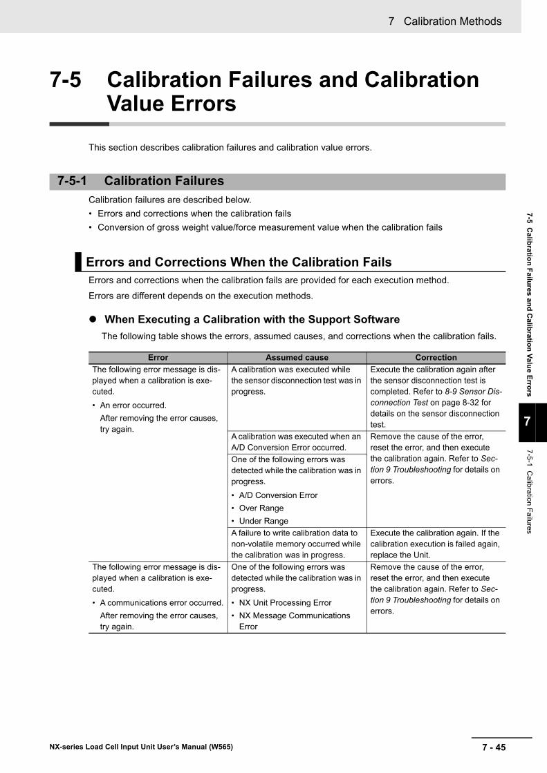
7 - 45
7 Calibration Methods
NX-series Load Cell Input Unit User’s Manual (W565)
7-5 C
alibratio
n F
ailures an
d C
alibratio
n V
alue E
rrors
7
7-5-1 C
alibration Failures
7-5 Calibration Failures and Calibration Value Errors
This section describes calibration failures and calibration value errors.
Calibration failures are described below.
• Errors and corrections when the calibration fails
• Conversion of gross weight value/force measurement value when the calibration fails
Errors and corrections when the calibration fails are provided for each execution method.
Errors are different depends on the execution methods.
When Executing a Calibration with the Support Software
The following table shows the errors, assumed causes, and corrections when the calibration fails.
7-5-1 Calibration Failures
Errors and Corrections When the Calibration Fails
Error Assumed cause Correction
The following error message is dis-played when a calibration is exe-cuted.
• An error occurred.
After removing the error causes, try again.
A calibration was executed while the sensor disconnection test was in progress.
Execute the calibration again after the sensor disconnection test is completed. Refer to 8-9 Sensor Dis-connection Test on page 8-32 for details on the sensor disconnection test.
A calibration was executed when an A/D Conversion Error occurred.
Remove the cause of the error, reset the error, and then execute the calibration again. Refer to Sec-tion 9 Troubleshooting for details on errors.
One of the following errors was detected while the calibration was in progress.
• A/D Conversion Error
• Over Range
• Under Range
A failure to write calibration data to non-volatile memory occurred while the calibration was in progress.
Execute the calibration again. If the calibration execution is failed again, replace the Unit.
The following error message is dis-played when a calibration is exe-cuted.
• A communications error occurred.
After removing the error causes, try again.
One of the following errors was detected while the calibration was in progress.
• NX Unit Processing Error
• NX Message Communications Error
Remove the cause of the error, reset the error, and then execute the calibration again. Refer to Sec-tion 9 Troubleshooting for details on errors.
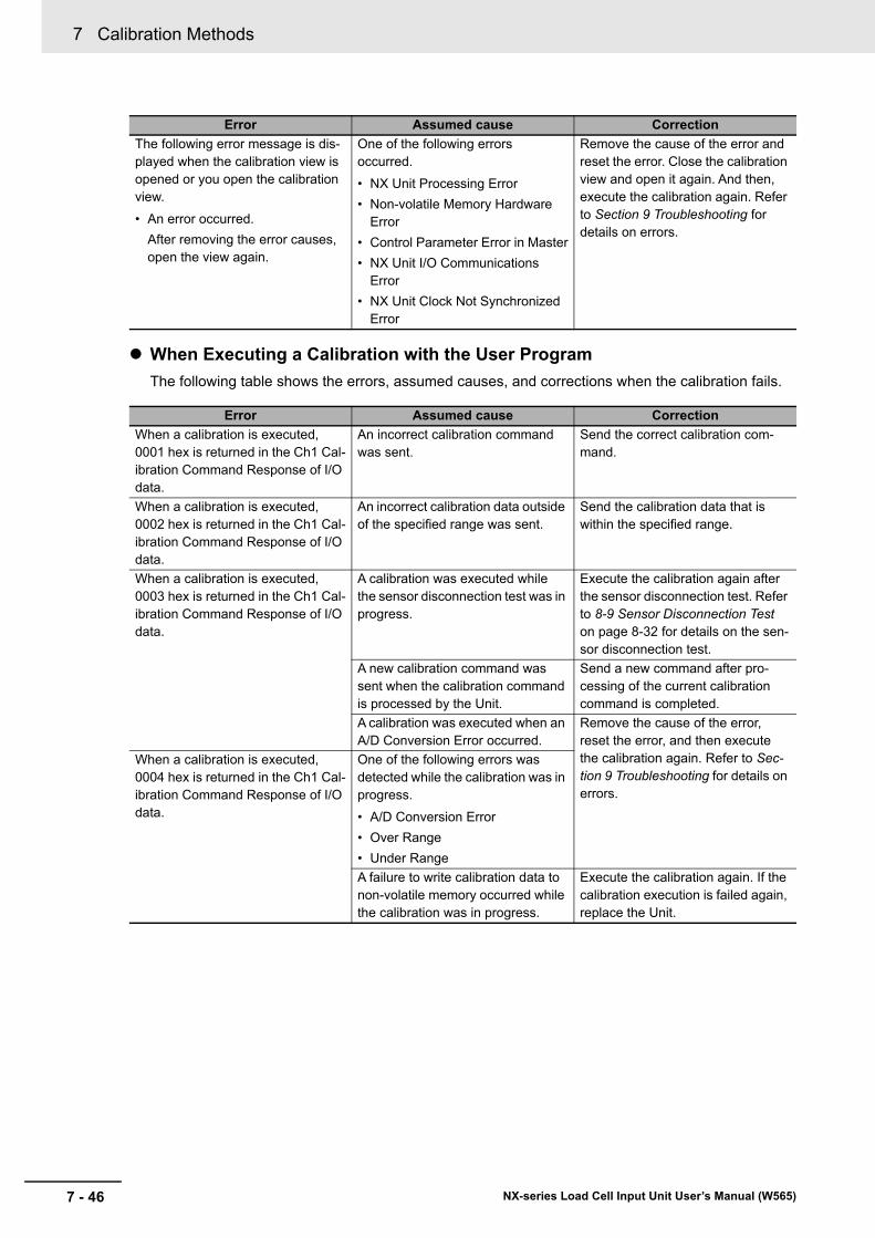
7 Calibration Methods
7 - 46 NX-series Load Cell Input Unit User’s Manual (W565)
When Executing a Calibration with the User Program
The following table shows the errors, assumed causes, and corrections when the calibration fails.
The following error message is dis-played when the calibration view is opened or you open the calibration view.
• An error occurred.
After removing the error causes, open the view again.
One of the following errors occurred.
• NX Unit Processing Error
• Non-volatile Memory Hardware Error
• Control Parameter Error in Master
• NX Unit I/O Communications Error
• NX Unit Clock Not Synchronized Error
Remove the cause of the error and reset the error. Close the calibration view and open it again. And then, execute the calibration again. Refer to Section 9 Troubleshooting for details on errors.
Error Assumed cause Correction
When a calibration is executed, 0001 hex is returned in the Ch1 Cal-ibration Command Response of I/O data.
An incorrect calibration command was sent.
Send the correct calibration com-mand.
When a calibration is executed, 0002 hex is returned in the Ch1 Cal-ibration Command Response of I/O data.
An incorrect calibration data outside of the specified range was sent.
Send the calibration data that is within the specified range.
When a calibration is executed, 0003 hex is returned in the Ch1 Cal-ibration Command Response of I/O data.
A calibration was executed while the sensor disconnection test was in progress.
Execute the calibration again after the sensor disconnection test. Refer to 8-9 Sensor Disconnection Test on page 8-32 for details on the sen-sor disconnection test.
A new calibration command was sent when the calibration command is processed by the Unit.
Send a new command after pro-cessing of the current calibration command is completed.
A calibration was executed when an A/D Conversion Error occurred.
Remove the cause of the error, reset the error, and then execute the calibration again. Refer to Sec-tion 9 Troubleshooting for details on errors.
When a calibration is executed, 0004 hex is returned in the Ch1 Cal-ibration Command Response of I/O data.
One of the following errors was detected while the calibration was in progress.
• A/D Conversion Error
• Over Range
• Under Range
A failure to write calibration data to non-volatile memory occurred while the calibration was in progress.
Execute the calibration again. If the calibration execution is failed again, replace the Unit.
Error Assumed cause Correction
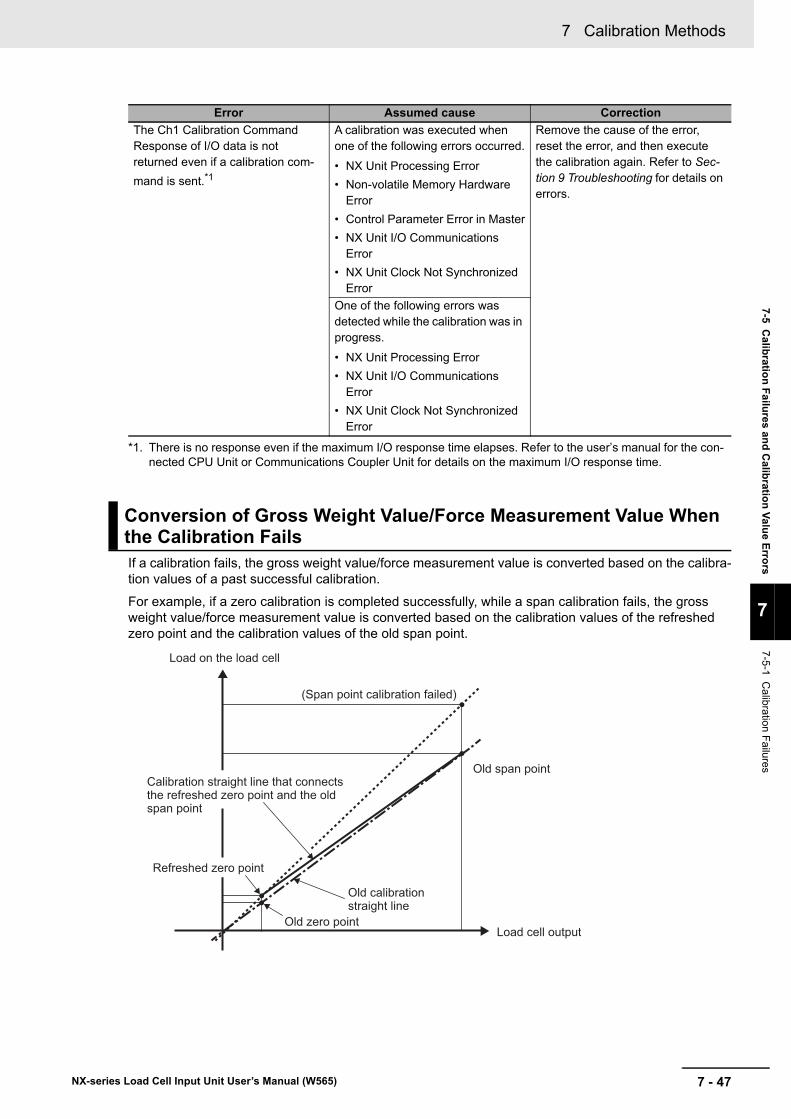
7 - 47
7 Calibration Methods
NX-series Load Cell Input Unit User’s Manual (W565)
7-5 C
alibratio
n F
ailures an
d C
alibratio
n V
alue E
rrors
7
7-5-1 C
alibration Failures
If a calibration fails, the gross weight value/force measurement value is converted based on the calibra-tion values of a past successful calibration.
For example, if a zero calibration is completed successfully, while a span calibration fails, the gross weight value/force measurement value is converted based on the calibration values of the refreshed zero point and the calibration values of the old span point.
The Ch1 Calibration Command Response of I/O data is not returned even if a calibration com-
mand is sent.*1
A calibration was executed when one of the following errors occurred.
• NX Unit Processing Error
• Non-volatile Memory Hardware Error
• Control Parameter Error in Master
• NX Unit I/O Communications Error
• NX Unit Clock Not Synchronized Error
Remove the cause of the error, reset the error, and then execute the calibration again. Refer to Sec-tion 9 Troubleshooting for details on errors.
One of the following errors was detected while the calibration was in progress.
• NX Unit Processing Error
• NX Unit I/O Communications Error
• NX Unit Clock Not Synchronized Error
*1. There is no response even if the maximum I/O response time elapses. Refer to the user’s manual for the con-nected CPU Unit or Communications Coupler Unit for details on the maximum I/O response time.
Conversion of Gross Weight Value/Force Measurement Value When the Calibration Fails
Error Assumed cause Correction
Load cell output
Load on the load cell
Old span point
Old calibration straight line
(Span point calibration failed)
Old zero point
Refreshed zero point
Calibration straight line that connects the refreshed zero point and the old span point
7 Calibration Methods
7 - 48 NX-series Load Cell Input Unit User’s Manual (W565)
The Load Cell Input Unit checks whether the correct calibration values are stored in the non-volatile memory inside the Unit when the power is turned ON. If the checked calibration values are not correct, one or both of the following events occur:
• Actual Load Calibration Value Error
• Unit Calibration Value Error
Refer to 9-3-3 Event Codes and Corrections for Errors on page 9-6 for event details.
7-5-2 Calibration Value Errors
8 - 1
8
NX-series Load Cell Input Unit User’s Manual (W565)
This section describes the functions of the Load Cell Input Unit.
8-1 Gravity Acceleration Correction . . . . . . . . . . . . . . . . . . . . . . . . . . . . . . . . . . 8-38-1-1 Function Applications and Overview . . . . . . . . . . . . . . . . . . . . . . . . . . . . . . . . . 8-3
8-1-2 Details on the Function . . . . . . . . . . . . . . . . . . . . . . . . . . . . . . . . . . . . . . . . . . . 8-3
8-1-3 Setting Method . . . . . . . . . . . . . . . . . . . . . . . . . . . . . . . . . . . . . . . . . . . . . . . . . 8-4
8-2 Digital Filtering . . . . . . . . . . . . . . . . . . . . . . . . . . . . . . . . . . . . . . . . . . . . . . . . 8-58-2-1 Function Applications and Overview . . . . . . . . . . . . . . . . . . . . . . . . . . . . . . . . . 8-5
8-2-2 Details on the Function . . . . . . . . . . . . . . . . . . . . . . . . . . . . . . . . . . . . . . . . . . . 8-5
8-2-3 Setting Method . . . . . . . . . . . . . . . . . . . . . . . . . . . . . . . . . . . . . . . . . . . . . . . . .8-11
8-3 Zero Set/Zero Reset . . . . . . . . . . . . . . . . . . . . . . . . . . . . . . . . . . . . . . . . . . . 8-138-3-1 Function Applications and Overview . . . . . . . . . . . . . . . . . . . . . . . . . . . . . . . . 8-13
8-3-2 Details on the Function . . . . . . . . . . . . . . . . . . . . . . . . . . . . . . . . . . . . . . . . . . 8-13
8-4 Zero Tracking . . . . . . . . . . . . . . . . . . . . . . . . . . . . . . . . . . . . . . . . . . . . . . . . 8-168-4-1 Function Applications and Overview . . . . . . . . . . . . . . . . . . . . . . . . . . . . . . . . 8-16
8-4-2 Details on the Function . . . . . . . . . . . . . . . . . . . . . . . . . . . . . . . . . . . . . . . . . . 8-16
8-4-3 Setting Method . . . . . . . . . . . . . . . . . . . . . . . . . . . . . . . . . . . . . . . . . . . . . . . . 8-19
8-5 Zero Point Range Over Detection . . . . . . . . . . . . . . . . . . . . . . . . . . . . . . . . 8-208-5-1 Function Applications and Overview . . . . . . . . . . . . . . . . . . . . . . . . . . . . . . . . 8-20
8-5-2 Details on the Function . . . . . . . . . . . . . . . . . . . . . . . . . . . . . . . . . . . . . . . . . . 8-20
8-5-3 Setting Method . . . . . . . . . . . . . . . . . . . . . . . . . . . . . . . . . . . . . . . . . . . . . . . . 8-22
8-6 Tare Subtraction . . . . . . . . . . . . . . . . . . . . . . . . . . . . . . . . . . . . . . . . . . . . . . 8-238-6-1 Function Applications and Overview . . . . . . . . . . . . . . . . . . . . . . . . . . . . . . . . 8-23
8-6-2 Calculating the Net Weight Value . . . . . . . . . . . . . . . . . . . . . . . . . . . . . . . . . . 8-23
8-6-3 One-touch Tare Subtraction . . . . . . . . . . . . . . . . . . . . . . . . . . . . . . . . . . . . . . 8-23
8-6-4 Digital Tare Subtraction . . . . . . . . . . . . . . . . . . . . . . . . . . . . . . . . . . . . . . . . . . 8-25
8-7 Stable Detection . . . . . . . . . . . . . . . . . . . . . . . . . . . . . . . . . . . . . . . . . . . . . . 8-278-7-1 Function Applications and Overview . . . . . . . . . . . . . . . . . . . . . . . . . . . . . . . . 8-27
8-7-2 Details on the Function . . . . . . . . . . . . . . . . . . . . . . . . . . . . . . . . . . . . . . . . . . 8-27
8-7-3 Setting Method . . . . . . . . . . . . . . . . . . . . . . . . . . . . . . . . . . . . . . . . . . . . . . . . 8-30
8-8 Over Range/Under Range Detection . . . . . . . . . . . . . . . . . . . . . . . . . . . . . 8-318-8-1 Function Applications and Overview . . . . . . . . . . . . . . . . . . . . . . . . . . . . . . . . 8-31
8-8-2 Details on the Function . . . . . . . . . . . . . . . . . . . . . . . . . . . . . . . . . . . . . . . . . . 8-31
Functions
8 Functions
8 - 2 NX-series Load Cell Input Unit User’s Manual (W565)
8-9 Sensor Disconnection Test . . . . . . . . . . . . . . . . . . . . . . . . . . . . . . . . . . . . . 8-328-9-1 Function Applications and Overview . . . . . . . . . . . . . . . . . . . . . . . . . . . . . . . . 8-32
8-9-2 Details on the Function . . . . . . . . . . . . . . . . . . . . . . . . . . . . . . . . . . . . . . . . . . 8-32
8-10 Input Value Refreshing Stop . . . . . . . . . . . . . . . . . . . . . . . . . . . . . . . . . . . . 8-358-10-1 Function Applications and Overview . . . . . . . . . . . . . . . . . . . . . . . . . . . . . . . . 8-35
8-10-2 Details on the Function . . . . . . . . . . . . . . . . . . . . . . . . . . . . . . . . . . . . . . . . . . 8-35
8-11 Peak Hold/Bottom Hold . . . . . . . . . . . . . . . . . . . . . . . . . . . . . . . . . . . . . . . . 8-378-11-1 Function Applications and Overview . . . . . . . . . . . . . . . . . . . . . . . . . . . . . . . . 8-37
8-11-2 Details on the Function . . . . . . . . . . . . . . . . . . . . . . . . . . . . . . . . . . . . . . . . . . 8-37
8-12 Data Tracing . . . . . . . . . . . . . . . . . . . . . . . . . . . . . . . . . . . . . . . . . . . . . . . . . . 8-418-12-1 Function Applications and Overview . . . . . . . . . . . . . . . . . . . . . . . . . . . . . . . . 8-41
8-12-2 Details on the Function . . . . . . . . . . . . . . . . . . . . . . . . . . . . . . . . . . . . . . . . . . 8-42
8-12-3 How to Execute Data Tracing . . . . . . . . . . . . . . . . . . . . . . . . . . . . . . . . . . . . . . 8-43
8-12-4 How to Check the Tracing Result . . . . . . . . . . . . . . . . . . . . . . . . . . . . . . . . . . . 8-45
8-13 Decimal Point Position Setting . . . . . . . . . . . . . . . . . . . . . . . . . . . . . . . . . . 8-478-13-1 Function Applications and Overview . . . . . . . . . . . . . . . . . . . . . . . . . . . . . . . . 8-47
8-13-2 Details on the Function . . . . . . . . . . . . . . . . . . . . . . . . . . . . . . . . . . . . . . . . . . 8-47
8-13-3 Setting Method . . . . . . . . . . . . . . . . . . . . . . . . . . . . . . . . . . . . . . . . . . . . . . . . . 8-48
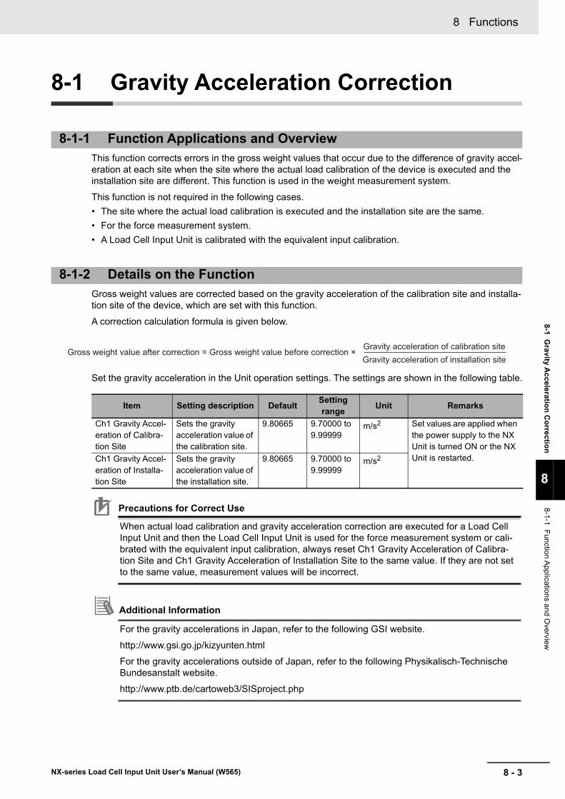
8 - 3
8 Functions
NX-series Load Cell Input Unit User’s Manual (W565)
8-1 Gravity A
cceleration
Co
rrection
8
8-1-1 F
unction Applicatio
ns and O
verview
8-1 Gravity Acceleration Correction
This function corrects errors in the gross weight values that occur due to the difference of gravity accel-eration at each site when the site where the actual load calibration of the device is executed and the installation site are different. This function is used in the weight measurement system.
This function is not required in the following cases.
• The site where the actual load calibration is executed and the installation site are the same.
• For the force measurement system.
• A Load Cell Input Unit is calibrated with the equivalent input calibration.
Gross weight values are corrected based on the gravity acceleration of the calibration site and installa-tion site of the device, which are set with this function.
A correction calculation formula is given below.
Set the gravity acceleration in the Unit operation settings. The settings are shown in the following table.
Precautions for Correct Use
When actual load calibration and gravity acceleration correction are executed for a Load Cell Input Unit and then the Load Cell Input Unit is used for the force measurement system or cali-brated with the equivalent input calibration, always reset Ch1 Gravity Acceleration of Calibra-tion Site and Ch1 Gravity Acceleration of Installation Site to the same value. If they are not set to the same value, measurement values will be incorrect.
Additional Information
For the gravity accelerations in Japan, refer to the following GSI website.
http://www.gsi.go.jp/kizyunten.html
For the gravity accelerations outside of Japan, refer to the following Physikalisch-Technische Bundesanstalt website.
http://www.ptb.de/cartoweb3/SISproject.php
8-1-1 Function Applications and Overview
8-1-2 Details on the Function
Item Setting description DefaultSetting range
Unit Remarks
Ch1 Gravity Accel-eration of Calibra-tion Site
Sets the gravity acceleration value of the calibration site.
9.80665 9.70000 to 9.99999
m/s2 Set values are applied when the power supply to the NX Unit is turned ON or the NX Unit is restarted.Ch1 Gravity Accel-
eration of Installa-tion Site
Sets the gravity acceleration value of the installation site.
9.80665 9.70000 to 9.99999
m/s2
Gross weight value after correction = Gross weight value before correction × Gravity acceleration of calibration siteGravity acceleration of installation site

8 Functions
8 - 4 NX-series Load Cell Input Unit User’s Manual (W565)
The method for setting the gravity acceleration with the Support Software is given below.
This section describes how to configure settings with the Sysmac Studio. For details on how to config-ure settings with Support Software other than Sysmac Studio, refer to the operation manual for the Sup-port Software that you are using.
1 Double-click the target Load Cell Input Unit in the Multiview Explorer to open the Edit Unit Oper-ation Settings Tab Page.
The following tab page is displayed.
2 Set the Ch1 Gravity Acceleration of Calibration Site and Ch1 Gravity Acceleration of Installation Site.
3 Click the Transfer to Unit Button.
The settings are transferred from the Support Software to the NX Unit.
The settings are reflected after the NX Unit is restarted.
Precautions for Safe Use
The Unit is required to restart after the transfer of Unit operation settings on the Support Soft-ware is completed. Always sufficiently check the safety at the connected devices before you transfer the Unit operation settings.
8-1-3 Setting Method
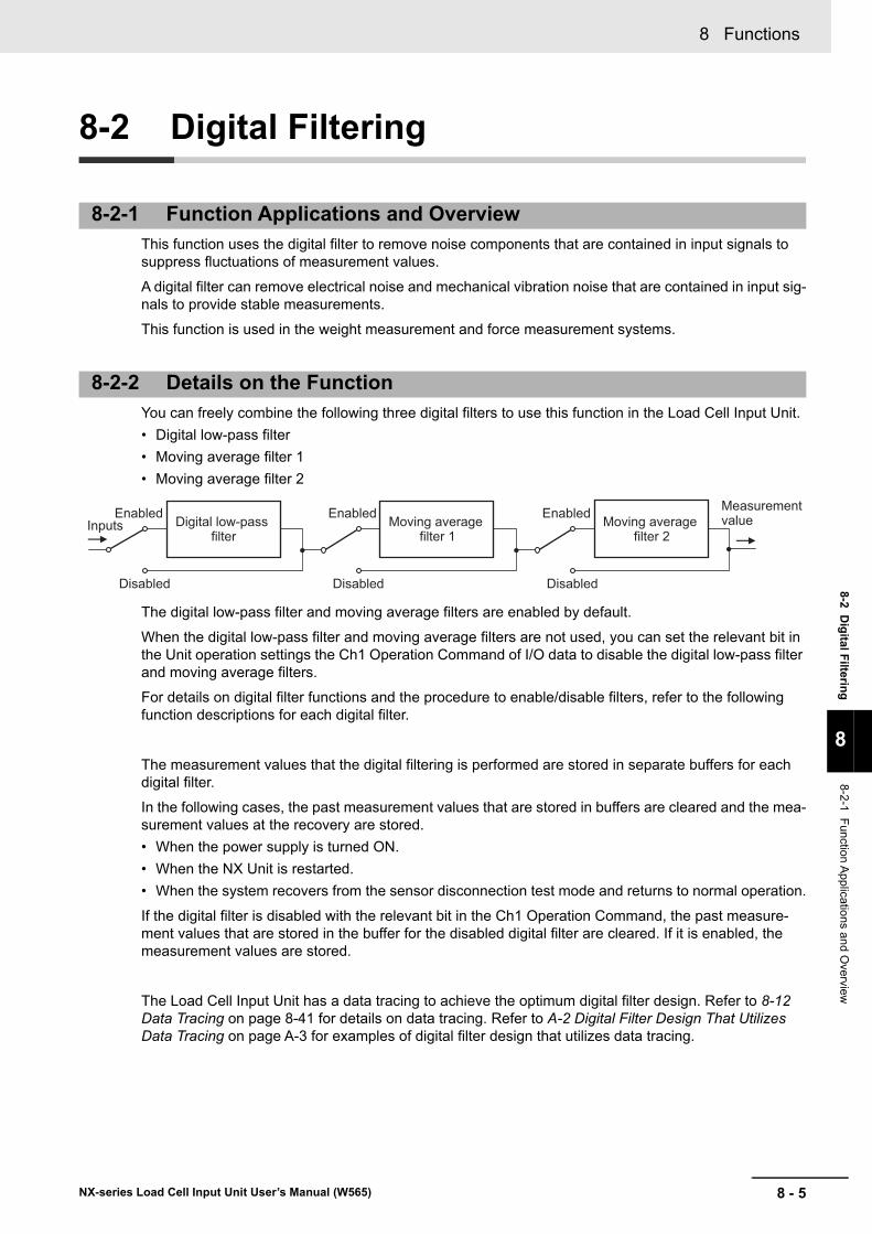
8 - 5
8 Functions
NX-series Load Cell Input Unit User’s Manual (W565)
8-2 Dig
ital Filterin
g
8
8-2-1 F
unction Applicatio
ns and O
verview
8-2 Digital Filtering
This function uses the digital filter to remove noise components that are contained in input signals to suppress fluctuations of measurement values.
A digital filter can remove electrical noise and mechanical vibration noise that are contained in input sig-nals to provide stable measurements.
This function is used in the weight measurement and force measurement systems.
You can freely combine the following three digital filters to use this function in the Load Cell Input Unit.
• Digital low-pass filter
• Moving average filter 1
• Moving average filter 2
The digital low-pass filter and moving average filters are enabled by default.
When the digital low-pass filter and moving average filters are not used, you can set the relevant bit in the Unit operation settings the Ch1 Operation Command of I/O data to disable the digital low-pass filter and moving average filters.
For details on digital filter functions and the procedure to enable/disable filters, refer to the following function descriptions for each digital filter.
The measurement values that the digital filtering is performed are stored in separate buffers for each digital filter.
In the following cases, the past measurement values that are stored in buffers are cleared and the mea-surement values at the recovery are stored.
• When the power supply is turned ON.
• When the NX Unit is restarted.
• When the system recovers from the sensor disconnection test mode and returns to normal operation.
If the digital filter is disabled with the relevant bit in the Ch1 Operation Command, the past measure-ment values that are stored in the buffer for the disabled digital filter are cleared. If it is enabled, the measurement values are stored.
The Load Cell Input Unit has a data tracing to achieve the optimum digital filter design. Refer to 8-12 Data Tracing on page 8-41 for details on data tracing. Refer to A-2 Digital Filter Design That Utilizes Data Tracing on page A-3 for examples of digital filter design that utilizes data tracing.
8-2-1 Function Applications and Overview
8-2-2 Details on the Function
InputsEnabled
Disabled
Enabled
Disabled
Enabled
Disabled
Measurement valueDigital low-pass
filterMoving average
filter 1Moving average
filter 2
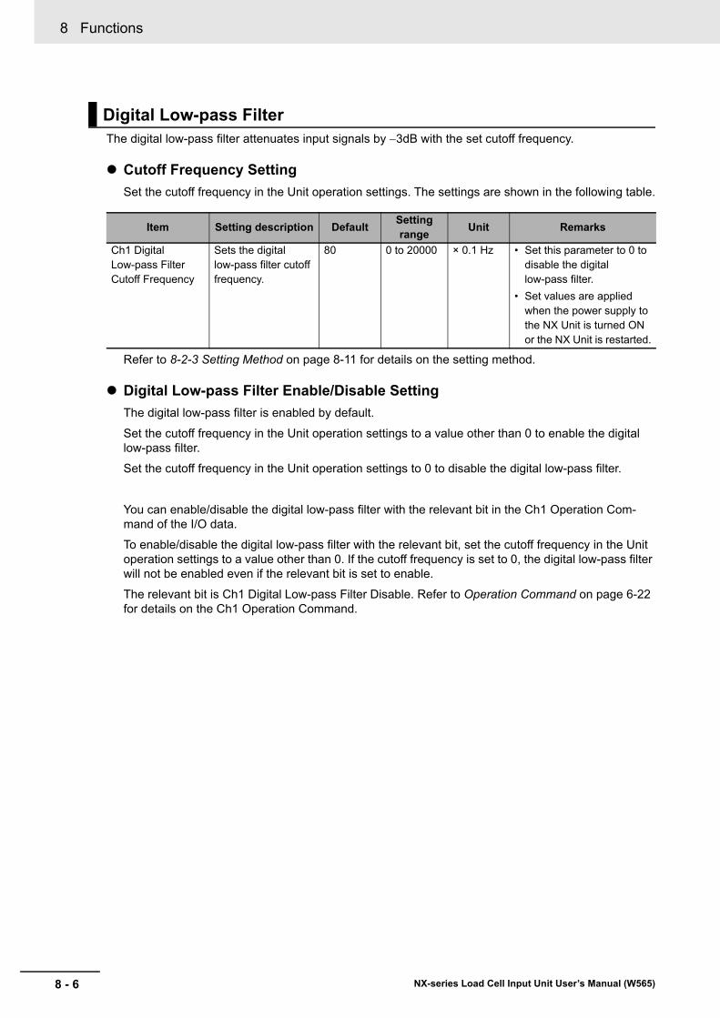
8 Functions
8 - 6 NX-series Load Cell Input Unit User’s Manual (W565)
The digital low-pass filter attenuates input signals by 3dB with the set cutoff frequency.
Cutoff Frequency Setting
Set the cutoff frequency in the Unit operation settings. The settings are shown in the following table.
Refer to 8-2-3 Setting Method on page 8-11 for details on the setting method.
Digital Low-pass Filter Enable/Disable Setting
The digital low-pass filter is enabled by default.
Set the cutoff frequency in the Unit operation settings to a value other than 0 to enable the digital low-pass filter.
Set the cutoff frequency in the Unit operation settings to 0 to disable the digital low-pass filter.
You can enable/disable the digital low-pass filter with the relevant bit in the Ch1 Operation Com-mand of the I/O data.
To enable/disable the digital low-pass filter with the relevant bit, set the cutoff frequency in the Unit operation settings to a value other than 0. If the cutoff frequency is set to 0, the digital low-pass filter will not be enabled even if the relevant bit is set to enable.
The relevant bit is Ch1 Digital Low-pass Filter Disable. Refer to Operation Command on page 6-22 for details on the Ch1 Operation Command.
Digital Low-pass Filter
Item Setting description DefaultSetting range
Unit Remarks
Ch1 Digital Low-pass Filter Cutoff Frequency
Sets the digital low-pass filter cutoff frequency.
80 0 to 20000 × 0.1 Hz • Set this parameter to 0 to disable the digital low-pass filter.
• Set values are applied when the power supply to the NX Unit is turned ON or the NX Unit is restarted.
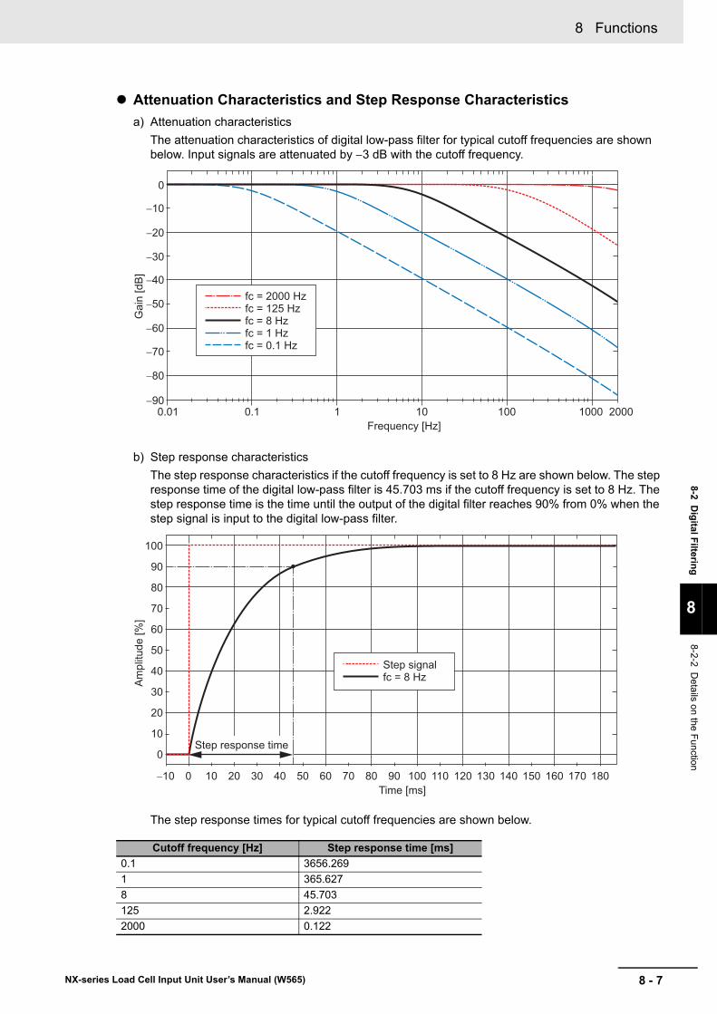
8 - 7
8 Functions
NX-series Load Cell Input Unit User’s Manual (W565)
8-2 Dig
ital Filterin
g
8
8-2-2 D
etails on
the Fun
ction
Attenuation Characteristics and Step Response Characteristics
a) Attenuation characteristics
The attenuation characteristics of digital low-pass filter for typical cutoff frequencies are shown below. Input signals are attenuated by 3 dB with the cutoff frequency.
b) Step response characteristics
The step response characteristics if the cutoff frequency is set to 8 Hz are shown below. The step response time of the digital low-pass filter is 45.703 ms if the cutoff frequency is set to 8 Hz. The step response time is the time until the output of the digital filter reaches 90% from 0% when the step signal is input to the digital low-pass filter.
The step response times for typical cutoff frequencies are shown below.
Cutoff frequency [Hz] Step response time [ms]
0.1 3656.269
1 365.627
8 45.703
125 2.922
2000 0.122
0
−10
−20
−30
−40
−50
−60
−70
−80
−900.01 0.1 1 10 100 1000 2000
fc = 2000 Hzfc = 125 Hzfc = 8 Hzfc = 1 Hzfc = 0.1 Hz
Gai
n [d
B]
Frequency [Hz]
100
90
80
70
60
50
40
30
20
10
0
−10 10 20 30 40 50 60 70 80 900 100 110 120 130 140 150 160 170 180
Ampl
itude
[%]
Time [ms]
Step response time
Step signalfc = 8 Hz
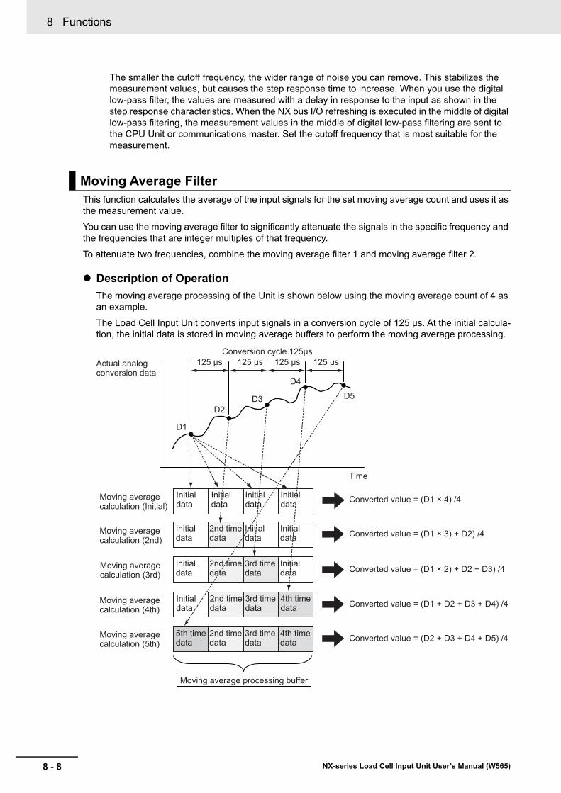
8 Functions
8 - 8 NX-series Load Cell Input Unit User’s Manual (W565)
The smaller the cutoff frequency, the wider range of noise you can remove. This stabilizes the measurement values, but causes the step response time to increase. When you use the digital low-pass filter, the values are measured with a delay in response to the input as shown in the step response characteristics. When the NX bus I/O refreshing is executed in the middle of digital low-pass filtering, the measurement values in the middle of digital low-pass filtering are sent to the CPU Unit or communications master. Set the cutoff frequency that is most suitable for the measurement.
This function calculates the average of the input signals for the set moving average count and uses it as the measurement value.
You can use the moving average filter to significantly attenuate the signals in the specific frequency and the frequencies that are integer multiples of that frequency.
To attenuate two frequencies, combine the moving average filter 1 and moving average filter 2.
Description of Operation
The moving average processing of the Unit is shown below using the moving average count of 4 as an example.
The Load Cell Input Unit converts input signals in a conversion cycle of 125 μs. At the initial calcula-tion, the initial data is stored in moving average buffers to perform the moving average processing.
Moving Average Filter
Initial data
Initial data
Initial data
Initial data
Initial data
2nd time data
Initial data
Initial data
Initial data
2nd time data
3rd time data
Initial data
Initial data
2nd time data
3rd time data
4th time data
5th time data
2nd time data
3rd time data
4th time data
Moving average calculation (Initial)
Moving average calculation (2nd)
Moving average calculation (3rd)
Moving average calculation (4th)
Moving average calculation (5th)
Converted value = (D1 × 4) /4
Converted value = (D1 × 3) + D2) /4
Converted value = (D1 × 2) + D2 + D3) /4
Converted value = (D1 + D2 + D3 + D4) /4
Converted value = (D2 + D3 + D4 + D5) /4
Actual analog conversion data
Conversion cycle 125μs125 μs 125 μs 125 μs 125 μs
Time
D1
D2D3
D4
D5
Moving average processing buffer
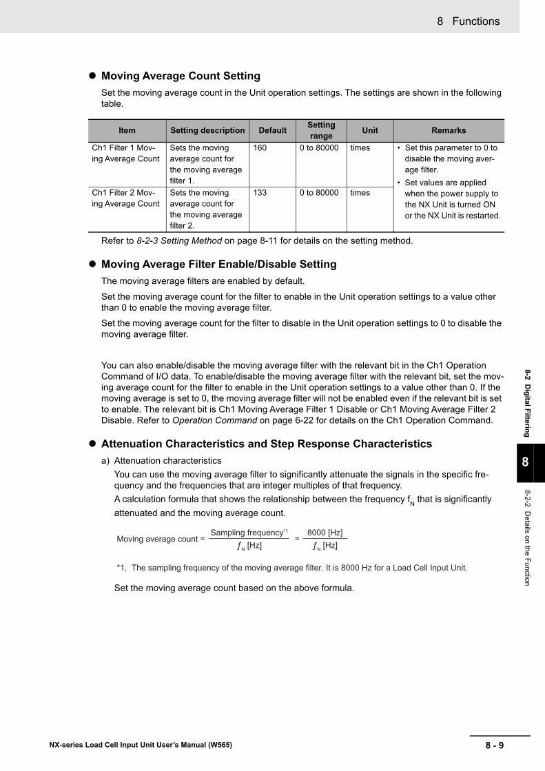
8 - 9
8 Functions
NX-series Load Cell Input Unit User’s Manual (W565)
8-2 Dig
ital Filterin
g
8
8-2-2 D
etails on
the Fun
ction
Moving Average Count Setting
Set the moving average count in the Unit operation settings. The settings are shown in the following table.
Refer to 8-2-3 Setting Method on page 8-11 for details on the setting method.
Moving Average Filter Enable/Disable Setting
The moving average filters are enabled by default.
Set the moving average count for the filter to enable in the Unit operation settings to a value other than 0 to enable the moving average filter.
Set the moving average count for the filter to disable in the Unit operation settings to 0 to disable the moving average filter.
You can also enable/disable the moving average filter with the relevant bit in the Ch1 Operation Command of I/O data. To enable/disable the moving average filter with the relevant bit, set the mov-ing average count for the filter to enable in the Unit operation settings to a value other than 0. If the moving average is set to 0, the moving average filter will not be enabled even if the relevant bit is set to enable. The relevant bit is Ch1 Moving Average Filter 1 Disable or Ch1 Moving Average Filter 2 Disable. Refer to Operation Command on page 6-22 for details on the Ch1 Operation Command.
Attenuation Characteristics and Step Response Characteristics
a) Attenuation characteristics
You can use the moving average filter to significantly attenuate the signals in the specific fre-quency and the frequencies that are integer multiples of that frequency.
A calculation formula that shows the relationship between the frequency fN that is significantly
attenuated and the moving average count.
Set the moving average count based on the above formula.
Item Setting description DefaultSetting range
Unit Remarks
Ch1 Filter 1 Mov-ing Average Count
Sets the moving average count for the moving average filter 1.
160 0 to 80000 times • Set this parameter to 0 to disable the moving aver-age filter.
• Set values are applied when the power supply to the NX Unit is turned ON or the NX Unit is restarted.
Ch1 Filter 2 Mov-ing Average Count
Sets the moving average count for the moving average filter 2.
133 0 to 80000 times
Moving average count = =Sampling frequency*1
ƒN [Hz]8000 [Hz]
ƒN [Hz]
*1. The sampling frequency of the moving average filter. It is 8000 Hz for a Load Cell Input Unit.
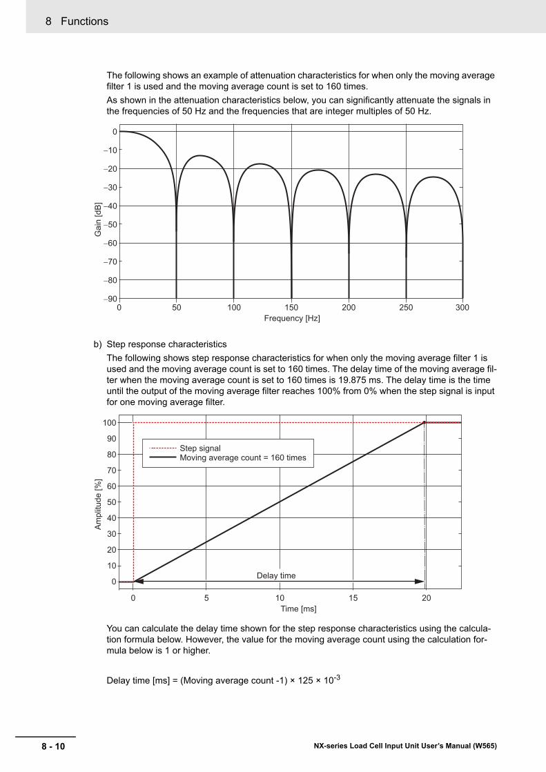
8 Functions
8 - 10 NX-series Load Cell Input Unit User’s Manual (W565)
The following shows an example of attenuation characteristics for when only the moving average filter 1 is used and the moving average count is set to 160 times.
As shown in the attenuation characteristics below, you can significantly attenuate the signals in the frequencies of 50 Hz and the frequencies that are integer multiples of 50 Hz.
b) Step response characteristics
The following shows step response characteristics for when only the moving average filter 1 is used and the moving average count is set to 160 times. The delay time of the moving average fil-ter when the moving average count is set to 160 times is 19.875 ms. The delay time is the time until the output of the moving average filter reaches 100% from 0% when the step signal is input for one moving average filter.
You can calculate the delay time shown for the step response characteristics using the calcula-tion formula below. However, the value for the moving average count using the calculation for-mula below is 1 or higher.
Delay time [ms] = (Moving average count -1) × 125 × 10-3
0
−10
−20
−30
−40
−50
−60
−70
−80
−900 50 100 150 200 250 300
Gai
n [d
B]
Frequency [Hz]
100
90
80
70
60
50
40
30
20
10
0
5 100 15 20
Ampl
itude
[%]
Time [ms]
Step signal
Delay time
Moving average count = 160 times
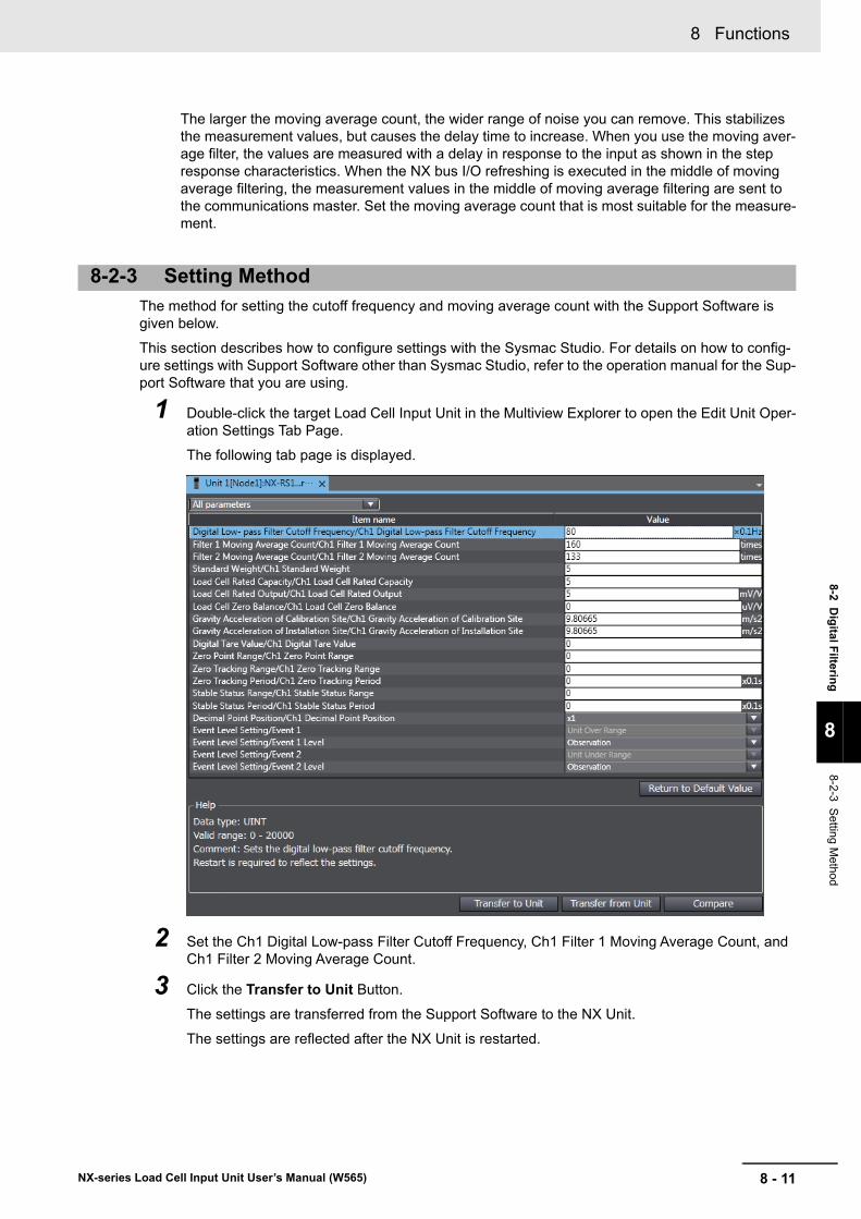
8 - 11
8 Functions
NX-series Load Cell Input Unit User’s Manual (W565)
8-2 Dig
ital Filterin
g
8
8-2-3 S
etting Method
The larger the moving average count, the wider range of noise you can remove. This stabilizes the measurement values, but causes the delay time to increase. When you use the moving aver-age filter, the values are measured with a delay in response to the input as shown in the step response characteristics. When the NX bus I/O refreshing is executed in the middle of moving average filtering, the measurement values in the middle of moving average filtering are sent to the communications master. Set the moving average count that is most suitable for the measure-ment.
The method for setting the cutoff frequency and moving average count with the Support Software is given below.
This section describes how to configure settings with the Sysmac Studio. For details on how to config-ure settings with Support Software other than Sysmac Studio, refer to the operation manual for the Sup-port Software that you are using.
1 Double-click the target Load Cell Input Unit in the Multiview Explorer to open the Edit Unit Oper-ation Settings Tab Page.
The following tab page is displayed.
2 Set the Ch1 Digital Low-pass Filter Cutoff Frequency, Ch1 Filter 1 Moving Average Count, and Ch1 Filter 2 Moving Average Count.
3 Click the Transfer to Unit Button.
The settings are transferred from the Support Software to the NX Unit.
The settings are reflected after the NX Unit is restarted.
8-2-3 Setting Method
8 Functions
8 - 12 NX-series Load Cell Input Unit User’s Manual (W565)
Precautions for Safe Use
The Unit is required to restart after the transfer of Unit operation settings on the Support Soft-ware is completed. Always sufficiently check the safety at the connected devices before you transfer the Unit operation settings.
8 - 13
8 Functions
NX-series Load Cell Input Unit User’s Manual (W565)
8-3 Zero
Set/Z
ero R
eset
8
8-3-1 F
unction Applicatio
ns and O
verview
8-3 Zero Set/Zero Reset
The zero set function corrects the gross weight value/force measurement value to be the zero point within the set range at a desired time. The zero reset function resets the correction that is performed with the zero set function.
Use this function to execute zero point correction in the following cases.
• The zero point is changed due to dust being adhered to the weighing machine
• To eliminate the fixed tare weight value from the gross weight value/force measurement value when you use the Unit after an equivalent input calibration is performed
• If the gross weight value/force measurement value with no load changes to a value other than 0 due to the installation method of the load cell when you use the Unit after an equivalent input calibration is performed
This function is used in the weight measurement and force measurement systems.
When the zero set is executed with the gross weight value/force measurement value within the zero point range, the gross weight value/force measurement value at the point of execution is corrected to be the zero point.
When the zero reset is executed, the zero point correction is reset and returns to the zero point at the point of calibration.
Use the Unit operation settings and I/O data to execute the zero set or the zero reset.
Use I/O data to check the execution status.
Refer to 6-2-1 Data Items for Allocation to I/O on page 6-13 for details on I/O data.
How to Execute the Function
Set the zero point range in the Unit operation settings. Set the zero point range to a value other than 0 to use the zero set or the zero reset. The zero set or the zero reset does not operate if the zero point range is set to 0.
After the zero point range is set, set the Ch1 Zero Set Execution bit in the Ch1 Operation Command of I/O data to execute the zero set or the zero reset.
Execution Status Check
You can check the zero set or the zero reset execution status with the Ch1 Zero Set Executing bit in the Ch1 Executing Status of I/O data.
You can also check if the zero point range is exceeded with the Ch1 Zero Point Range Over bit in the Ch1 Detection Status of I/O data.
8-3-1 Function Applications and Overview
8-3-2 Details on the Function
How to Execute the Function and Check the Execution Status
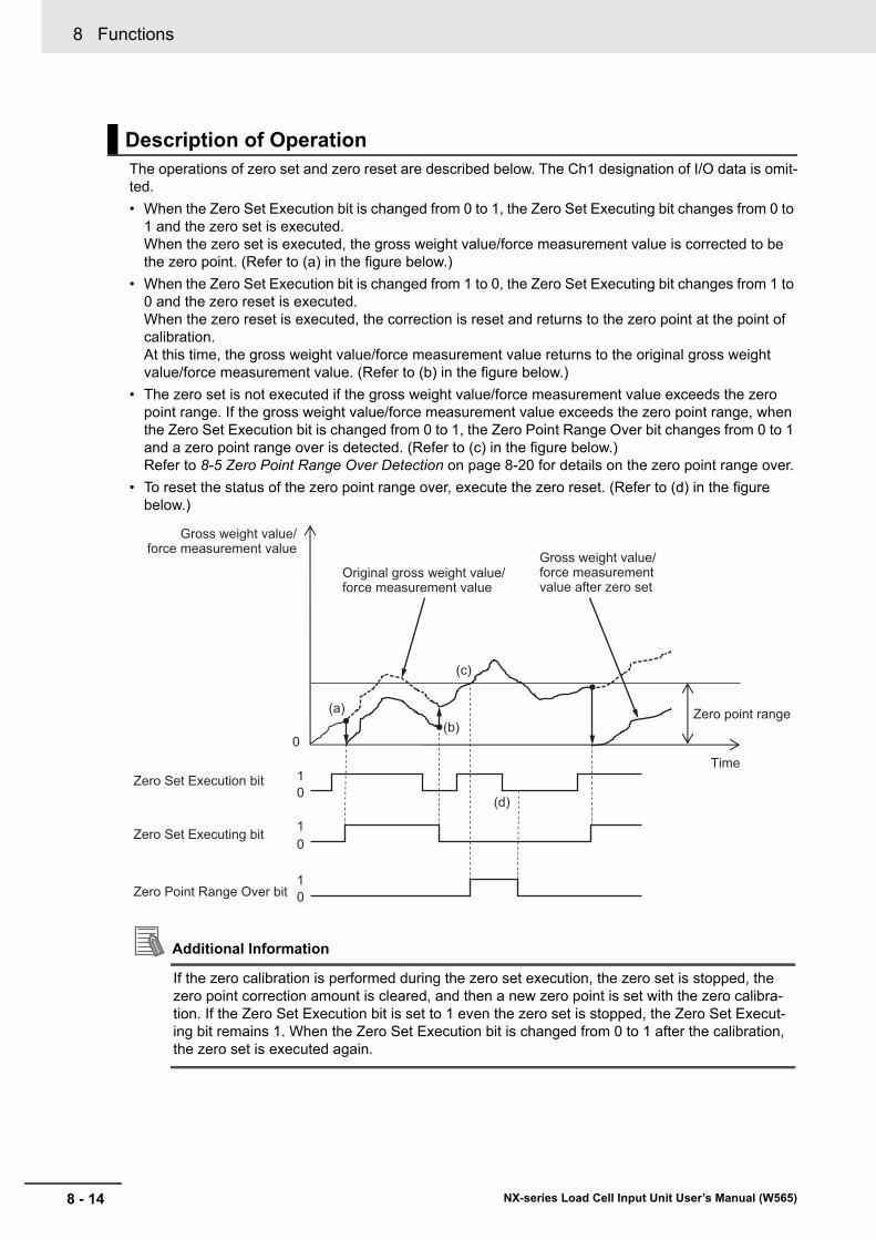
8 Functions
8 - 14 NX-series Load Cell Input Unit User’s Manual (W565)
The operations of zero set and zero reset are described below. The Ch1 designation of I/O data is omit-ted.
• When the Zero Set Execution bit is changed from 0 to 1, the Zero Set Executing bit changes from 0 to 1 and the zero set is executed. When the zero set is executed, the gross weight value/force measurement value is corrected to be the zero point. (Refer to (a) in the figure below.)
• When the Zero Set Execution bit is changed from 1 to 0, the Zero Set Executing bit changes from 1 to 0 and the zero reset is executed. When the zero reset is executed, the correction is reset and returns to the zero point at the point of calibration.At this time, the gross weight value/force measurement value returns to the original gross weight value/force measurement value. (Refer to (b) in the figure below.)
• The zero set is not executed if the gross weight value/force measurement value exceeds the zero point range. If the gross weight value/force measurement value exceeds the zero point range, when the Zero Set Execution bit is changed from 0 to 1, the Zero Point Range Over bit changes from 0 to 1 and a zero point range over is detected. (Refer to (c) in the figure below.) Refer to 8-5 Zero Point Range Over Detection on page 8-20 for details on the zero point range over.
• To reset the status of the zero point range over, execute the zero reset. (Refer to (d) in the figure below.)
Additional Information
If the zero calibration is performed during the zero set execution, the zero set is stopped, the zero point correction amount is cleared, and then a new zero point is set with the zero calibra-tion. If the Zero Set Execution bit is set to 1 even the zero set is stopped, the Zero Set Execut-ing bit remains 1. When the Zero Set Execution bit is changed from 0 to 1 after the calibration, the zero set is executed again.
Description of Operation
Time1Zero Set Execution bit
Gross weight value/force measurement value
0
1Zero Set Executing bit0
0
Zero Point Range Over bit
Original gross weight value/force measurement value
Gross weight value/force measurement value after zero set
01
(a)(b)
(c)
(d)
Zero point range
8 - 15
8 Functions
NX-series Load Cell Input Unit User’s Manual (W565)
8-3 Zero
Set/Z
ero R
eset
8
8-3-2 D
etails on
the Fun
ction
Set the zero point range in the Unit operation settings. Refer to 8-5 Zero Point Range Over Detection on page 8-20 for the setting of zero point range.
Parameters
8 Functions
8 - 16 NX-series Load Cell Input Unit User’s Manual (W565)
8-4 Zero Tracking
This function automatically corrects the zero point within the set range.
If the zero point is changed due to a change in the ambient operating temperature after calibration or dust being adhered to the weighing machine, this function is used to correct the zero point. This func-tion is used in the weight measurement system.
If the zero tracking period elapses while the fluctuation of the gross weight value is kept within the zero point range and 0 ± zero tracking range, the gross weight value is automatically corrected to 0.
You can use this function by setting the following items in the Unit operation settings.
• Zero point range
• Zero tracking range
• Zero tracking period
Set the above items to a value other than 0 to use the zero tracking.
The zero tracking does not operate when any of the above items is set to 0.
8-4-1 Function Applications and Overview
8-4-2 Details on the Function
How to Execute the Function

8 - 17
8 Functions
NX-series Load Cell Input Unit User’s Manual (W565)
8-4 Zero
Trac
king
8
8-4-2 D
etails on
the Fun
ction
The operation of zero tracking is described below.
• If the zero tracking period elapses while the fluctuation of the gross weight value is kept within the zero point range and 0 ± zero tracking range, the gross weight value is automatically corrected to 0. (Refer to (a) in the figure below.) After the gross weight value is corrected to 0, the above operation (hereinafter zero tracking operation) is repeated and the gross weight value is corrected repeatedly.
• While the gross weight value after the correction exceeds the 0 ± zero tracking range, the zero track-ing operation is stopped. (Refer to period between (b) and (c) in the figure below.) When the gross weight value fluctuates again within the 0 ± zero tracking range, the zero tracking operation is resumed.
• While the original gross weight value exceeds the zero point range, the zero tracking operation is stopped. (Refer to period between (d) and (e) in the figure below.)
Additional Information
• If the gross weight value does not change to 0 even the zero tracking is used without a mea-sured material, remove any adhered materials from the weighing machine or perform the zero calibration again.
• If the zero calibration is performed during the zero tracking operation, the zero tracking oper-ation is paused and a new zero point is set with the zero calibration. When the calibration is completed, the zero tracking operation is resumed.
Description of Operation
Time
Zero point range
Gross weight value
0
Zero tracking range
Original gross weight value
Gross weight value after correction
Zero tracking period
(a)
(b)(c)
(d) (e) Zero point after correction
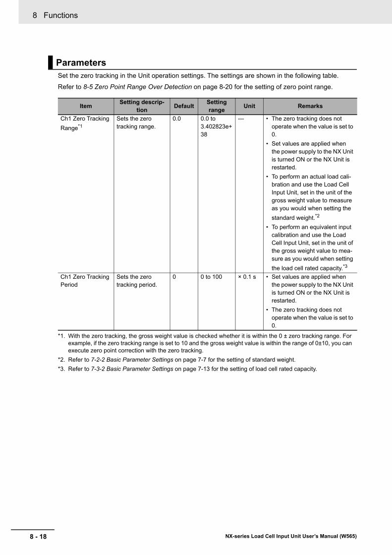
8 Functions
8 - 18 NX-series Load Cell Input Unit User’s Manual (W565)
Set the zero tracking in the Unit operation settings. The settings are shown in the following table.
Refer to 8-5 Zero Point Range Over Detection on page 8-20 for the setting of zero point range.
Parameters
ItemSetting descrip-
tionDefault
Setting range
Unit Remarks
Ch1 Zero Tracking
Range*1
*1. With the zero tracking, the gross weight value is checked whether it is within the 0 ± zero tracking range. For example, if the zero tracking range is set to 10 and the gross weight value is within the range of 0±10, you can execute zero point correction with the zero tracking.
Sets the zero tracking range.
0.0 0.0 to 3.402823e+38
--- • The zero tracking does not operate when the value is set to 0.
• Set values are applied when the power supply to the NX Unit is turned ON or the NX Unit is restarted.
• To perform an actual load cali-bration and use the Load Cell Input Unit, set in the unit of the gross weight value to measure as you would when setting the
standard weight.*2
• To perform an equivalent input calibration and use the Load Cell Input Unit, set in the unit of the gross weight value to mea-sure as you would when setting
the load cell rated capacity.*3
*2. Refer to 7-2-2 Basic Parameter Settings on page 7-7 for the setting of standard weight.
*3. Refer to 7-3-2 Basic Parameter Settings on page 7-13 for the setting of load cell rated capacity.
Ch1 Zero Tracking Period
Sets the zero tracking period.
0 0 to 100 × 0.1 s • Set values are applied when the power supply to the NX Unit is turned ON or the NX Unit is restarted.
• The zero tracking does not operate when the value is set to 0.
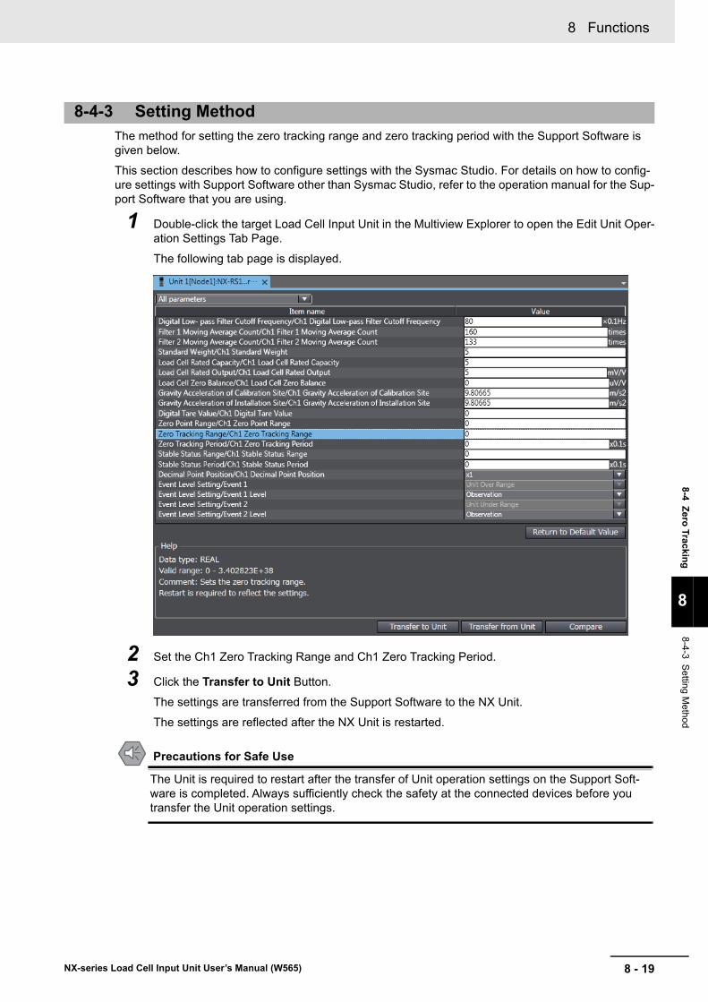
8 - 19
8 Functions
NX-series Load Cell Input Unit User’s Manual (W565)
8-4 Zero
Trac
king
8
8-4-3 S
etting Method
The method for setting the zero tracking range and zero tracking period with the Support Software is given below.
This section describes how to configure settings with the Sysmac Studio. For details on how to config-ure settings with Support Software other than Sysmac Studio, refer to the operation manual for the Sup-port Software that you are using.
1 Double-click the target Load Cell Input Unit in the Multiview Explorer to open the Edit Unit Oper-ation Settings Tab Page.
The following tab page is displayed.
2 Set the Ch1 Zero Tracking Range and Ch1 Zero Tracking Period.
3 Click the Transfer to Unit Button.
The settings are transferred from the Support Software to the NX Unit.
The settings are reflected after the NX Unit is restarted.
Precautions for Safe Use
The Unit is required to restart after the transfer of Unit operation settings on the Support Soft-ware is completed. Always sufficiently check the safety at the connected devices before you transfer the Unit operation settings.
8-4-3 Setting Method
8 Functions
8 - 20 NX-series Load Cell Input Unit User’s Manual (W565)
8-5 Zero Point Range Over Detection
This function detects when the gross weight value/force measurement value exceeds the set zero point range.
You need to set this function to use the zero set, zero reset, and zero tracking.
This function is used in the weight measurement and force measurement systems.
You can check if the zero point range is exceeded with the Ch1 Zero Point Range Over bit in the Ch1 Detection Status of I/O data.
Refer to 6-2 Specifications of I/O Data on page 6-13 for details on I/O data.
The operation varies between the zero set, zero reset, and zero tracking. Operations of each function are provided below.
Bit Operations for Zero Set and Zero Reset
Refer to the description of operation in 8-3 Zero Set/Zero Reset on page 8-13 for details on opera-tions of the Ch1 Zero Point Range Over bit.
Bit Operations for Zero Tracking
The zero point range over is not detected even if the gross weight value/force measurement value exceeds the set zero point range. Therefore, the Ch1 Zero Point Range Over bit remains 0. The zero point range is used only to execute and stop the zero tracking operations.
8-5-1 Function Applications and Overview
8-5-2 Details on the Function
How to Check If the Zero Point Range Is Exceeded
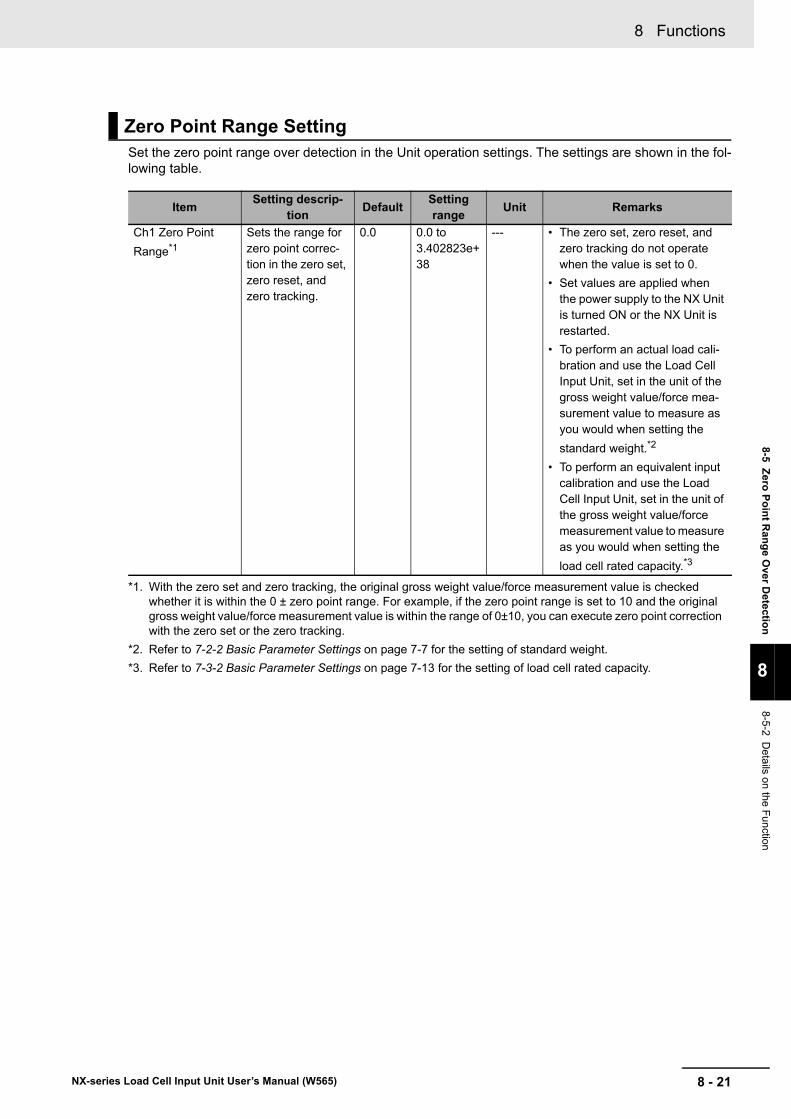
8 - 21
8 Functions
NX-series Load Cell Input Unit User’s Manual (W565)
8-5 Zero
Po
int R
ang
e O
ver Detectio
n
8
8-5-2 D
etails on
the Fun
ction
Set the zero point range over detection in the Unit operation settings. The settings are shown in the fol-lowing table.
Zero Point Range Setting
ItemSetting descrip-
tionDefault
Setting range
Unit Remarks
Ch1 Zero Point
Range*1
*1. With the zero set and zero tracking, the original gross weight value/force measurement value is checked whether it is within the 0 ± zero point range. For example, if the zero point range is set to 10 and the original gross weight value/force measurement value is within the range of 0±10, you can execute zero point correction with the zero set or the zero tracking.
Sets the range for zero point correc-tion in the zero set, zero reset, and zero tracking.
0.0 0.0 to 3.402823e+38
--- • The zero set, zero reset, and zero tracking do not operate when the value is set to 0.
• Set values are applied when the power supply to the NX Unit is turned ON or the NX Unit is restarted.
• To perform an actual load cali-bration and use the Load Cell Input Unit, set in the unit of the gross weight value/force mea-surement value to measure as you would when setting the
standard weight.*2
• To perform an equivalent input calibration and use the Load Cell Input Unit, set in the unit of the gross weight value/force measurement value to measure as you would when setting the
load cell rated capacity.*3
*2. Refer to 7-2-2 Basic Parameter Settings on page 7-7 for the setting of standard weight.
*3. Refer to 7-3-2 Basic Parameter Settings on page 7-13 for the setting of load cell rated capacity.

8 Functions
8 - 22 NX-series Load Cell Input Unit User’s Manual (W565)
The method for setting the zero point range with the Support Software is given below.
This section describes how to configure settings with the Sysmac Studio. For details on how to config-ure settings with Support Software other than Sysmac Studio, refer to the operation manual for the Sup-port Software that you are using.
1 Double-click the target Load Cell Input Unit in the Multiview Explorer to open the Edit Unit Oper-ation Settings Tab Page.
The following tab page is displayed.
2 Set the Ch1 Zero Point Range.
3 Click the Transfer to Unit Button.
The settings are transferred from the Support Software to the NX Unit.
The settings are reflected after the NX Unit is restarted.
Precautions for Safe Use
The Unit is required to restart after the transfer of Unit operation settings on the Support Soft-ware is completed. Always sufficiently check the safety at the connected devices before you transfer the Unit operation settings.
8-5-3 Setting Method
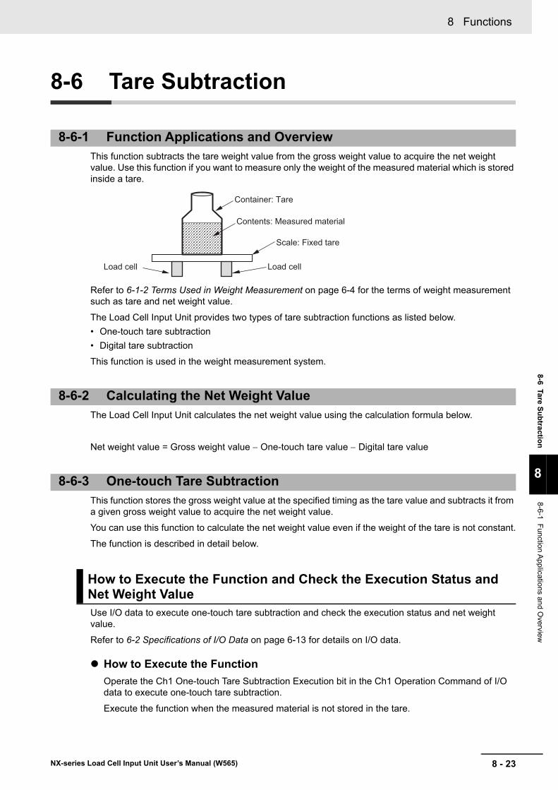
8 - 23
8 Functions
NX-series Load Cell Input Unit User’s Manual (W565)
8-6 Tare Su
btractio
n
8
8-6-1 F
unction Applicatio
ns and O
verview
8-6 Tare Subtraction
This function subtracts the tare weight value from the gross weight value to acquire the net weight value. Use this function if you want to measure only the weight of the measured material which is stored inside a tare.
Refer to 6-1-2 Terms Used in Weight Measurement on page 6-4 for the terms of weight measurement such as tare and net weight value.
The Load Cell Input Unit provides two types of tare subtraction functions as listed below.
• One-touch tare subtraction
• Digital tare subtraction
This function is used in the weight measurement system.
The Load Cell Input Unit calculates the net weight value using the calculation formula below.
Net weight value = Gross weight value One-touch tare value Digital tare value
This function stores the gross weight value at the specified timing as the tare value and subtracts it from a given gross weight value to acquire the net weight value.
You can use this function to calculate the net weight value even if the weight of the tare is not constant.
The function is described in detail below.
Use I/O data to execute one-touch tare subtraction and check the execution status and net weight value.
Refer to 6-2 Specifications of I/O Data on page 6-13 for details on I/O data.
How to Execute the Function
Operate the Ch1 One-touch Tare Subtraction Execution bit in the Ch1 Operation Command of I/O data to execute one-touch tare subtraction.
Execute the function when the measured material is not stored in the tare.
8-6-1 Function Applications and Overview
8-6-2 Calculating the Net Weight Value
8-6-3 One-touch Tare Subtraction
How to Execute the Function and Check the Execution Status and Net Weight Value
Scale: Fixed tare
Load cellLoad cell
Container: Tare
Contents: Measured material
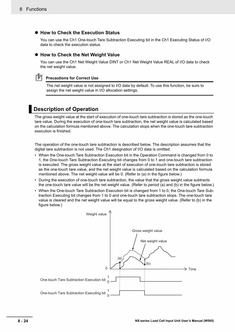
8 Functions
8 - 24 NX-series Load Cell Input Unit User’s Manual (W565)
How to Check the Execution Status
You can use the Ch1 One-touch Tare Subtraction Executing bit in the Ch1 Executing Status of I/O data to check the execution status.
How to Check the Net Weight Value
You can use the Ch1 Net Weight Value DINT or Ch1 Net Weight Value REAL of I/O data to check the net weight value.
Precautions for Correct Use
The net weight value is not assigned to I/O data by default. To use this function, be sure to assign the net weight value in I/O allocation settings.
The gross weight value at the start of execution of one-touch tare subtraction is stored as the one-touch tare value. During the execution of one-touch tare subtraction, the net weight value is calculated based on the calculation formula mentioned above. The calculation stops when the one-touch tare subtraction execution is finished.
The operation of the one-touch tare subtraction is described below. The description assumes that the digital tare subtraction is not used. The Ch1 designation of I/O data is omitted.
• When the One-touch Tare Subtraction Execution bit in the Operation Command is changed from 0 to 1, the One-touch Tare Subtraction Executing bit changes from 0 to 1 and one-touch tare subtraction is executed. The gross weight value at the start of execution of one-touch tare subtraction is stored as the one-touch tare value, and the net weight value is calculated based on the calculation formula mentioned above. The net weight value will be 0. (Refer to (a) in the figure below.)
• During the execution of one-touch tare subtraction, the value that the gross weight value subtracts the one-touch tare value will be the net weight value. (Refer to period (a) and (b) in the figure below.)
• When the One-touch Tare Subtraction Execution bit is changed from 1 to 0, the One-touch Tare Sub-traction Executing bit changes from 1 to 0 and one-touch tare subtraction stops. The one-touch tare value is cleared and the net weight value will be equal to the gross weight value. (Refer to (b) in the figure below.)
Description of Operation
Time
One-touch Tare Subtraction Execution bit
Weight value
One-touch Tare Subtraction Executing bit
0
Gross weight value
Net weight value
(a)(b)
01
01
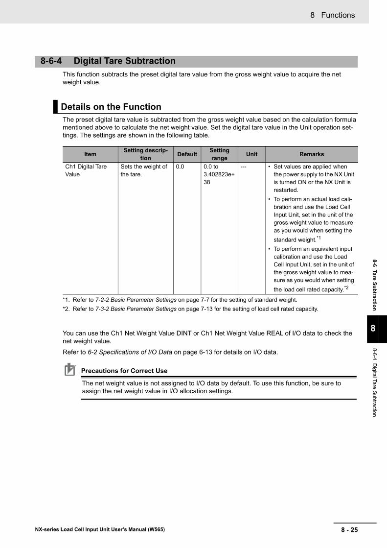
8 - 25
8 Functions
NX-series Load Cell Input Unit User’s Manual (W565)
8-6 Tare Su
btractio
n
8
8-6-4 D
igital Tare Subtraction
This function subtracts the preset digital tare value from the gross weight value to acquire the net weight value.
The preset digital tare value is subtracted from the gross weight value based on the calculation formula mentioned above to calculate the net weight value. Set the digital tare value in the Unit operation set-tings. The settings are shown in the following table.
You can use the Ch1 Net Weight Value DINT or Ch1 Net Weight Value REAL of I/O data to check the net weight value.
Refer to 6-2 Specifications of I/O Data on page 6-13 for details on I/O data.
Precautions for Correct Use
The net weight value is not assigned to I/O data by default. To use this function, be sure to assign the net weight value in I/O allocation settings.
8-6-4 Digital Tare Subtraction
Details on the Function
ItemSetting descrip-
tionDefault
Setting range
Unit Remarks
Ch1 Digital Tare Value
Sets the weight of the tare.
0.0 0.0 to 3.402823e+38
--- • Set values are applied when the power supply to the NX Unit is turned ON or the NX Unit is restarted.
• To perform an actual load cali-bration and use the Load Cell Input Unit, set in the unit of the gross weight value to measure as you would when setting the
standard weight.*1
• To perform an equivalent input calibration and use the Load Cell Input Unit, set in the unit of the gross weight value to mea-sure as you would when setting
the load cell rated capacity.*2
*1. Refer to 7-2-2 Basic Parameter Settings on page 7-7 for the setting of standard weight.
*2. Refer to 7-3-2 Basic Parameter Settings on page 7-13 for the setting of load cell rated capacity.
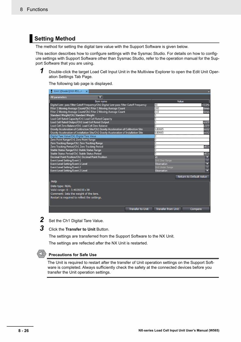
8 Functions
8 - 26 NX-series Load Cell Input Unit User’s Manual (W565)
The method for setting the digital tare value with the Support Software is given below.
This section describes how to configure settings with the Sysmac Studio. For details on how to config-ure settings with Support Software other than Sysmac Studio, refer to the operation manual for the Sup-port Software that you are using.
1 Double-click the target Load Cell Input Unit in the Multiview Explorer to open the Edit Unit Oper-ation Settings Tab Page.
The following tab page is displayed.
2 Set the Ch1 Digital Tare Value.
3 Click the Transfer to Unit Button.
The settings are transferred from the Support Software to the NX Unit.
The settings are reflected after the NX Unit is restarted.
Precautions for Safe Use
The Unit is required to restart after the transfer of Unit operation settings on the Support Soft-ware is completed. Always sufficiently check the safety at the connected devices before you transfer the Unit operation settings.
Setting Method
8 - 27
8 Functions
NX-series Load Cell Input Unit User’s Manual (W565)
8-7 Stab
le Detectio
n
8
8-7-1 F
unction Applicatio
ns and O
verview
8-7 Stable Detection
This function detects whether the gross weight value is stable. Use it for stability check before and after weight measurement.
This function is used in the weight measurement system.
Stability is detected if the stable status period elapses while the fluctuation of the gross weight value is kept within the range of gross weight value ± stable status range.
Use the Unit operation settings to execute the stable detection.
Use I/O data to check the execution status. Refer to 6-2-1 Data Items for Allocation to I/O on page 6-13 for details on I/O data.
How to Execute the Function
You can use this function by setting the stable status range and stable status period in the Unit oper-ation settings.
To use the stable detection, set the stable status range and stable status period to a value other than 0. The stable detection does not operate when either the stable status range or the stable status period is set to 0.
How to Check the Execution Status
You can use Ch1 Stable Status bit in the Ch1 Detection Status of I/O data to check the execution status of the stable detection.
Refer to 6-2 Specifications of I/O Data on page 6-13 for details on I/O data.
8-7-1 Function Applications and Overview
8-7-2 Details on the Function
How to Execute the Function and Check the Execution Status
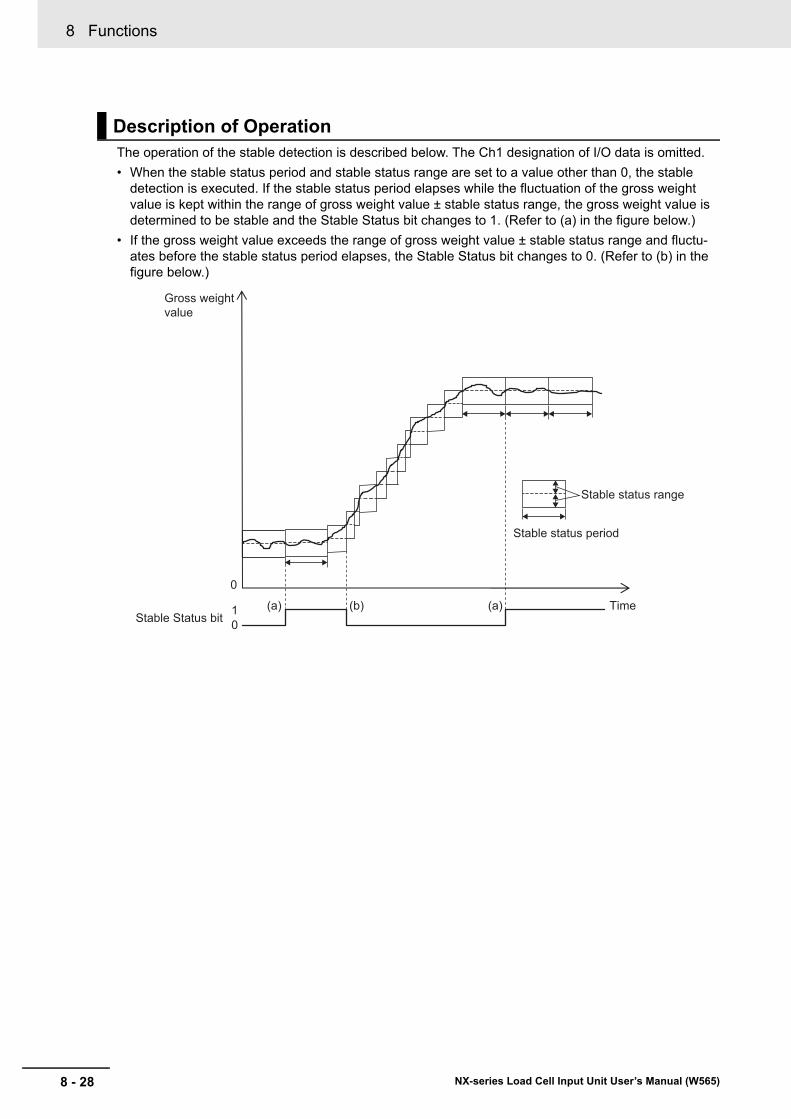
8 Functions
8 - 28 NX-series Load Cell Input Unit User’s Manual (W565)
The operation of the stable detection is described below. The Ch1 designation of I/O data is omitted.
• When the stable status period and stable status range are set to a value other than 0, the stable detection is executed. If the stable status period elapses while the fluctuation of the gross weight value is kept within the range of gross weight value ± stable status range, the gross weight value is determined to be stable and the Stable Status bit changes to 1. (Refer to (a) in the figure below.)
• If the gross weight value exceeds the range of gross weight value ± stable status range and fluctu-ates before the stable status period elapses, the Stable Status bit changes to 0. (Refer to (b) in the figure below.)
Description of Operation
Time
Gross weight value
0
Stable Status bit
Stable status period
Stable status range
10
(a) (a)(b)
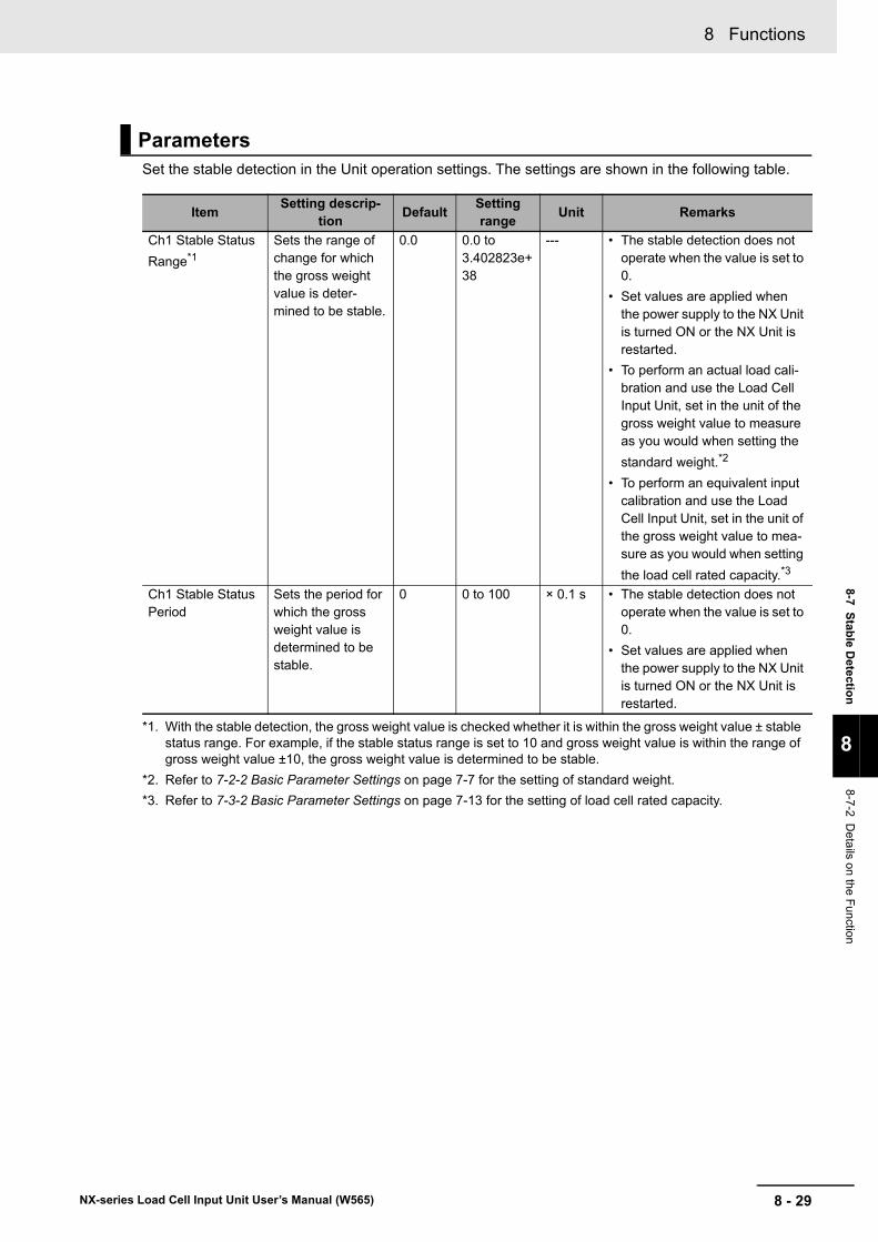
8 - 29
8 Functions
NX-series Load Cell Input Unit User’s Manual (W565)
8-7 Stab
le Detectio
n
8
8-7-2 D
etails on
the Fun
ction
Set the stable detection in the Unit operation settings. The settings are shown in the following table.
Parameters
ItemSetting descrip-
tionDefault
Setting range
Unit Remarks
Ch1 Stable Status
Range*1
*1. With the stable detection, the gross weight value is checked whether it is within the gross weight value ± stable status range. For example, if the stable status range is set to 10 and gross weight value is within the range of gross weight value ±10, the gross weight value is determined to be stable.
Sets the range of change for which the gross weight value is deter-mined to be stable.
0.0 0.0 to 3.402823e+38
--- • The stable detection does not operate when the value is set to 0.
• Set values are applied when the power supply to the NX Unit is turned ON or the NX Unit is restarted.
• To perform an actual load cali-bration and use the Load Cell Input Unit, set in the unit of the gross weight value to measure as you would when setting the
standard weight.*2
• To perform an equivalent input calibration and use the Load Cell Input Unit, set in the unit of the gross weight value to mea-sure as you would when setting
the load cell rated capacity.*3
*2. Refer to 7-2-2 Basic Parameter Settings on page 7-7 for the setting of standard weight.
*3. Refer to 7-3-2 Basic Parameter Settings on page 7-13 for the setting of load cell rated capacity.
Ch1 Stable Status Period
Sets the period for which the gross weight value is determined to be stable.
0 0 to 100 × 0.1 s • The stable detection does not operate when the value is set to 0.
• Set values are applied when the power supply to the NX Unit is turned ON or the NX Unit is restarted.
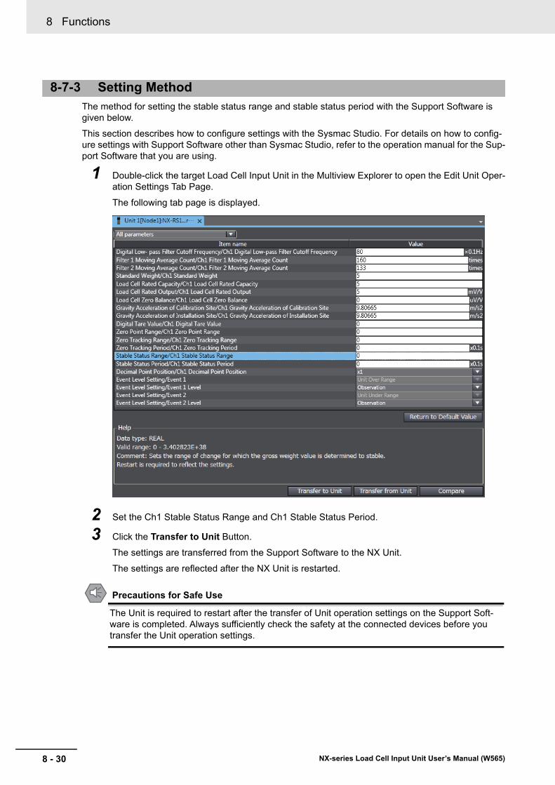
8 Functions
8 - 30 NX-series Load Cell Input Unit User’s Manual (W565)
The method for setting the stable status range and stable status period with the Support Software is given below.
This section describes how to configure settings with the Sysmac Studio. For details on how to config-ure settings with Support Software other than Sysmac Studio, refer to the operation manual for the Sup-port Software that you are using.
1 Double-click the target Load Cell Input Unit in the Multiview Explorer to open the Edit Unit Oper-ation Settings Tab Page.
The following tab page is displayed.
2 Set the Ch1 Stable Status Range and Ch1 Stable Status Period.
3 Click the Transfer to Unit Button.
The settings are transferred from the Support Software to the NX Unit.
The settings are reflected after the NX Unit is restarted.
Precautions for Safe Use
The Unit is required to restart after the transfer of Unit operation settings on the Support Soft-ware is completed. Always sufficiently check the safety at the connected devices before you transfer the Unit operation settings.
8-7-3 Setting Method
8 - 31
8 Functions
NX-series Load Cell Input Unit User’s Manual (W565)
8-8 Over R
ang
e/Un
der R
ang
e Detectio
n
8
8-8-1 F
unction Applicatio
ns and O
verview
8-8 Over Range/Under Range Detection
This function detects when the input signal exceeds the input conversion range.
This function is used in the weight measurement and force measurement systems.
You can use the Ch1 Over Range bit in the Ch1 Detection Status of I/O data to check if an over range is detected.
You can use the Ch1 Under Range bit in the Ch1 Detection Status of I/O data to check if an under range is detected.
Refer to 6-2 Specifications of I/O Data on page 6-13 for details on I/O data.
When an over range is detected, an Over Range event occurs. When an under range is detected, an Under Range event occurs. Refer to 9-3-3 Event Codes and Corrections for Errors on page 9-6 for event details.
The operations of the over range/under range detection are described below. The Ch1 designation of I/O data is omitted.
• If the input signal exceeds the upper limit (5.5 mV/V) of the input conversion range, the measurement values are fixed to the measurement values when an error occurs. At this time, the Over Range bit changes to 1 and an Over Range event occurs. Refer to 9-6 Measurement Values Used When an Error Occurs on page 9-30 for information on measurement values when an error occurs.
• If the input signal is below the lower limit (5.5 mV/V) of the input conversion range, the measure-ment values are fixed to the measurement values when an error occurs. At this time, the Under Range bit changes to 1 and an Under Range event occurs. Refer to 9-6 Measurement Values Used When an Error Occurs on page 9-30 for information on measurement values when an error occurs.
• When the input signal returns to the input conversion range, the fixing is canceled and the values become the normal measurement values.
• When the cause of the error is removed and the error is reset, the Over Range bit or Under Range bit changes to 0. The Over Range bit or Under Range bit remains 1 until the error is reset.
No setting is required.
8-8-1 Function Applications and Overview
8-8-2 Details on the Function
How to Check the Detection Result
Description of Operation
Setting Method
8 Functions
8 - 32 NX-series Load Cell Input Unit User’s Manual (W565)
8-9 Sensor Disconnection Test
This function tests if the cable that connects the Load Cell Input Unit and load cell is disconnected. You can check if the connection cable is disconnected when starting up, operating, and maintaining devices.
This function is used in the weight measurement and force measurement systems.
Precautions for Correct Use
Observe the following precautions when you use the sensor disconnection test.
• Use 6-wire connections.
• During the sensor disconnection test, you cannot measure the gross weight value or force measurement value.
Use I/O data to execute the sensor disconnection test and check the execution status. Refer to 6-2 Specifications of I/O Data on page 6-13 for details on I/O data.
Use I/O data and event codes to check the test results. Refer to 9-3-3 Event Codes and Corrections for Errors on page 9-6 for event code details.
How to Execute the Function
Operate the Ch1 Sensor Disconnection Test Execution bit in the Ch1 Operation Command of I/O data to execute the sensor disconnection test.
How to Check the Execution Status
You can use the Ch1 Sensor Disconnection Test Executing bit in the Ch1 Executing Status of I/O data to check the execution status.
How to Check the Test Result
You can use the Ch1 Sensor Disconnected Error bit in the Ch1 Detection Status of I/O data to check if the cable is disconnected.
When a disconnection is detected, a Sensor Disconnected Error event occurs.
8-9-1 Function Applications and Overview
8-9-2 Details on the Function
How to Execute the Function and Check the Execution Status and Test Result

8 - 33
8 Functions
NX-series Load Cell Input Unit User’s Manual (W565)
8-9 Sen
sor D
isco
nn
ection
Test
8
8-9-2 D
etails on
the Fun
ction
The operation of the sensor disconnection test is described below. The Ch1 designation of I/O data is omitted.
• When the Sensor Disconnection Test Execution bit is changed from 0 to 1, the Sensor Disconnection Test Executing bit changes from 0 to 1. At this time, the Load Cell Input Unit enters the sensor dis-connection test mode and the sensor disconnection test starts. (Refer to (a) in the figure below.) During the sensor disconnection test, you cannot measure the gross weight value or force measure-ment value. (Refer to period (a) and (d) in the following figure.)
• When an error exists, the Sensor Disconnected Error bit changes to 1 and a Sensor Disconnected Error event occurs. (Refer to (b) in the figure below.)
• t1 time is required for a disconnection to be detected after the Sensor Disconnection Test Execution bit is changed from 0 to 1. (Refer to (b) in the figure below.)
• During the sensor disconnection test, the sensor disconnection test is executed repeatedly.
• After t2 elapses since the Sensor Disconnection Test Execution bit is changed from 1 to 0, the Sen-sor Disconnection Test Executing bit changes from 1 to 0 and the system changes to normal opera-tion. (Refer to (c) and (d) in the figure below.)
• The Sensor Disconnected Error bit remains 1 until the error is reset. When the cause of the error is removed and the error is reset, the Sensor Disconnected Error bit changes from 1 to 0. (Refer to (e) in the figure below.)
t1: Time required from the sensor disconnection test is executed until the disconnection is detected.
Maximum 260 ms + Maximum I/O response time*1 is required.
t2: Time required from the Sensor Disconnection Test Execution bit changes from 1 to 0 until the sys-
tem changes to the normal operation mode. Maximum 300 ms + Maximum I/O response time*1 is required.
*1. Refer to the user’s manual for the connected CPU Unit or Communications Coupler Unit for details on the maximum I/O response time.
Precautions for Correct Use
Change the Sensor Disconnection Test Execution bit from 1 to 0 after the Sensor Disconnec-tion Test Executing bit changes from 0 to 1. Otherwise, the sensor disconnection test may not execute.
Description of Operation
Sensor Disconnection Test Execution bit
Sensor Disconnection Test Executing bit
Sensor Disconnected Error bit
Error is reset
Disconnection is detected
Sensor disconnection test mode Normal operationNormal operationUnit status
(a)
(b)
(c)
(d)
(e)t1
t2
0
1
0
1
0
1
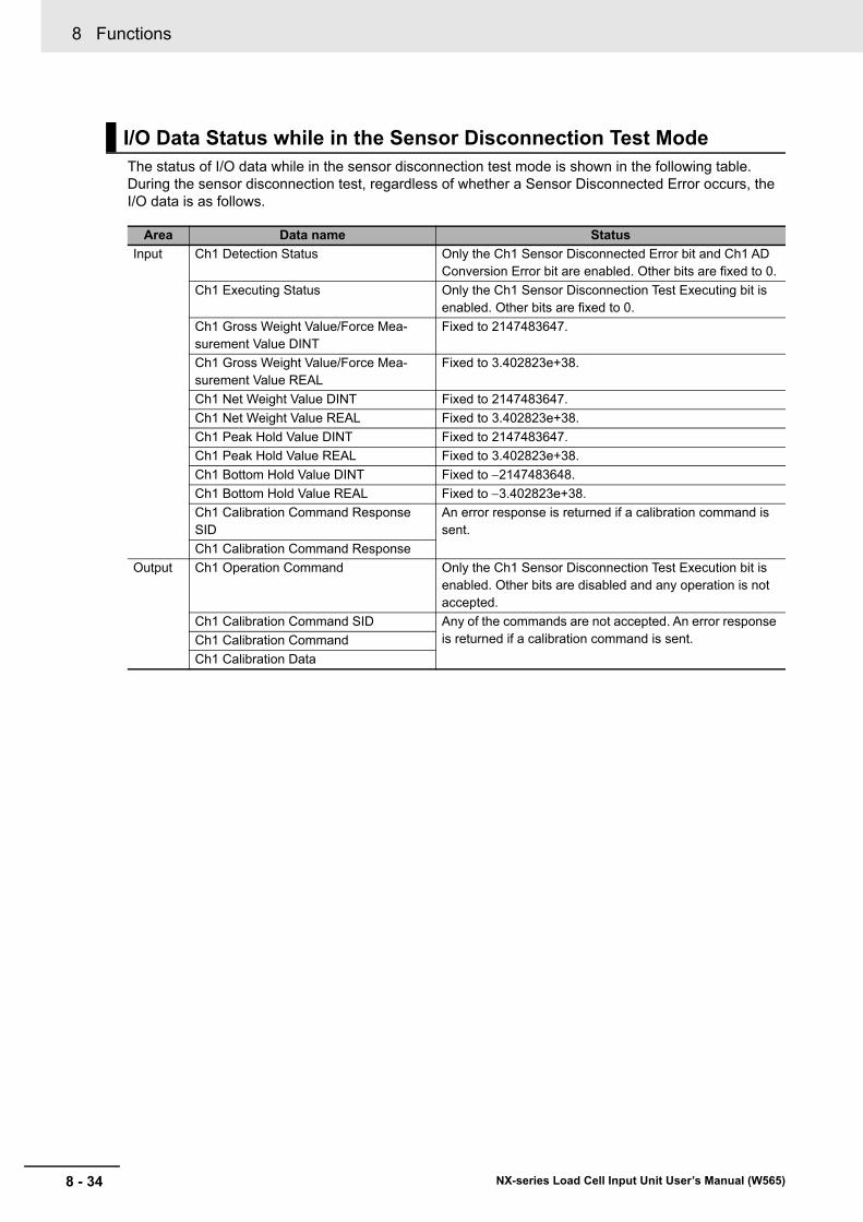
8 Functions
8 - 34 NX-series Load Cell Input Unit User’s Manual (W565)
The status of I/O data while in the sensor disconnection test mode is shown in the following table. During the sensor disconnection test, regardless of whether a Sensor Disconnected Error occurs, the I/O data is as follows.
I/O Data Status while in the Sensor Disconnection Test Mode
Area Data name Status
Input Ch1 Detection Status Only the Ch1 Sensor Disconnected Error bit and Ch1 AD Conversion Error bit are enabled. Other bits are fixed to 0.
Ch1 Executing Status Only the Ch1 Sensor Disconnection Test Executing bit is enabled. Other bits are fixed to 0.
Ch1 Gross Weight Value/Force Mea-surement Value DINT
Fixed to 2147483647.
Ch1 Gross Weight Value/Force Mea-surement Value REAL
Fixed to 3.402823e+38.
Ch1 Net Weight Value DINT Fixed to 2147483647.
Ch1 Net Weight Value REAL Fixed to 3.402823e+38.
Ch1 Peak Hold Value DINT Fixed to 2147483647.
Ch1 Peak Hold Value REAL Fixed to 3.402823e+38.
Ch1 Bottom Hold Value DINT Fixed to 2147483648.
Ch1 Bottom Hold Value REAL Fixed to 3.402823e+38.
Ch1 Calibration Command Response SID
An error response is returned if a calibration command is sent.
Ch1 Calibration Command Response
Output Ch1 Operation Command Only the Ch1 Sensor Disconnection Test Execution bit is enabled. Other bits are disabled and any operation is not accepted.
Ch1 Calibration Command SID Any of the commands are not accepted. An error response is returned if a calibration command is sent.Ch1 Calibration Command
Ch1 Calibration Data
8 - 35
8 Functions
NX-series Load Cell Input Unit User’s Manual (W565)
8-10 Inp
ut V
alue R
efreshin
g S
top
8
8-10-1 F
unction Applications a
nd Overview
8-10 Input Value Refreshing Stop
This function stops refreshing the input value in a specified period.
Use this function in the following cases.
• To avoid overshooting and undershooting due to mechanical vibrations occurred at a fixed timing
• To avoid overshooting and undershooting when filling is started
This function is used in the weight measurement and force measurement systems.
Use I/O data to execute the input value refreshing stop and check the execution status. Refer to 6-2 Specifications of I/O Data on page 6-13 for details on I/O data.
How to Execute the Function
Operate the Ch1 Input Value Refreshing Stop bit in the Ch1 Operation Command of I/O data to exe-cute the input value refreshing stop.
How to Check the Execution Status
You can use the Ch1 Input Value Refreshing Stopping bit in the Ch1 Executing Status of I/O data to check the execution status.
8-10-1 Function Applications and Overview
8-10-2 Details on the Function
How to Execute the Function and Check the Execution Status
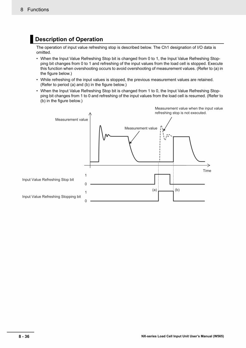
8 Functions
8 - 36 NX-series Load Cell Input Unit User’s Manual (W565)
The operation of input value refreshing stop is described below. The Ch1 designation of I/O data is omitted.
• When the Input Value Refreshing Stop bit is changed from 0 to 1, the Input Value Refreshing Stop-ping bit changes from 0 to 1 and refreshing of the input values from the load cell is stopped. Execute this function when overshooting occurs to avoid overshooting of measurement values. (Refer to (a) in the figure below.)
• While refreshing of the input values is stopped, the previous measurement values are retained. (Refer to period (a) and (b) in the figure below.)
• When the Input Value Refreshing Stop bit is changed from 1 to 0, the Input Value Refreshing Stop-ping bit changes from 1 to 0 and refreshing of the input values from the load cell is resumed. (Refer to (b) in the figure below.)
Description of Operation
0
1Input Value Refreshing Stop bit
Measurement value
Measurement value
Time
0
1 (a) (b)
Input Value Refreshing Stopping bit
Measurement value when the input value refreshing stop is not executed.
8 - 37
8 Functions
NX-series Load Cell Input Unit User’s Manual (W565)
8-11 Peak H
old
/Bo
ttom
Ho
ld
8
8-11-1 Function A
pplications and Overview
8-11 Peak Hold/Bottom Hold
This function continues holding the peak value or the bottom value of the force measurement value in a specified period.
This function is used in the force measurement system.
Use I/O data to execute the peak hold or bottom hold, check the execution status, and check the peak hold value or bottom hold value.
Refer to 6-2 Specifications of I/O Data on page 6-13 for details on I/O data.
How to Execute and Cancel the Function
Operate the Ch1 Hold Execution bit in the Ch1 Operation Command of I/O data to execute the peak hold or bottom hold.
Operate the Ch1 Hold Value Clear bit in the Ch1 Operation Command of I/O data to cancel the peak hold or bottom hold.
How to Check the Execution Status
You can use the Ch1 Hold Executing bit in the Ch1 Executing Status of I/O data to check the execu-tion status.
How to Check the Hold Values
You can use the Ch1 Peak Hold Value DINT or Ch1 Peak Hold Value REAL of I/O data to check the peal hold value.
You can use the Ch1 Bottom Hold Value DINT or Ch1 Bottom Hold value REAL of I/O data to check the bottom hold value.
Precautions for Correct Use
• The peak hold value is not assigned to I/O data by default. To use the peak hold, be sure to assign the peak hold value in I/O allocation settings.
• The bottom hold value is not assigned to I/O data by default. To use the bottom hold, be sure to assign the bottom hold value in I/O allocation settings.
8-11-1 Function Applications and Overview
8-11-2 Details on the Function
How to Execute and Cancel the Function and Check the ExecutionStatus and Hold Values
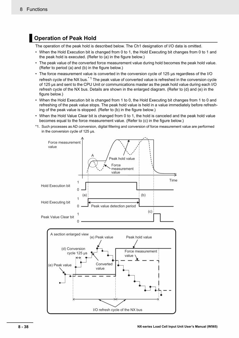
8 Functions
8 - 38 NX-series Load Cell Input Unit User’s Manual (W565)
The operation of the peak hold is described below. The Ch1 designation of I/O data is omitted.
• When the Hold Execution bit is changed from 0 to 1, the Hold Executing bit changes from 0 to 1 and the peak hold is executed. (Refer to (a) in the figure below.)
• The peak value of the converted force measurement value during hold becomes the peak hold value. (Refer to period (a) and (b) in the figure below.)
• The force measurement value is converted in the conversion cycle of 125 μs regardless of the I/O
refresh cycle of the NX bus.* 1 The peak value of converted value is refreshed in the conversion cycle of 125 μs and sent to the CPU Unit or communications master as the peak hold value during each I/O refresh cycle of the NX bus. Details are shown in the enlarged diagram. (Refer to (d) and (e) in the figure below.)
• When the Hold Execution bit is changed from 1 to 0, the Hold Executing bit changes from 1 to 0 and refreshing of the peak value stops. The peak hold value is held in a value immediately before refresh-ing of the peak value is stopped. (Refer to (b) in the figure below.)
• When the Hold Value Clear bit is changed from 0 to 1, the hold is canceled and the peak hold value becomes equal to the force measurement value. (Refer to (c) in the figure below.)
*1. Such processes as AD conversion, digital filtering and conversion of force measurement value are performed in the conversion cycle of 125 μs.
Operation of Peak Hold
Peak Value Clear bit
Peak hold value
Peak value detection period
Force measurement value
0
1Hold Execution bit
(e) Peak value
(e) Peak value
I/O refresh cycle of the NX bus
A section enlarged viewPeak hold value
0
1
Force measurement value
Converted value
0
1Hold Executing bit
Time
Force measurement value
A
(a) (b)
(c)
(d) Conversion cycle 125 μs
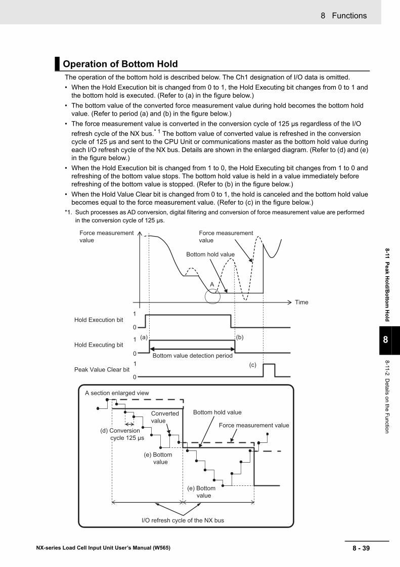
8 - 39
8 Functions
NX-series Load Cell Input Unit User’s Manual (W565)
8-11 Peak H
old
/Bo
ttom
Ho
ld
8
8-11-2 Details on the F
unction
The operation of the bottom hold is described below. The Ch1 designation of I/O data is omitted.
• When the Hold Execution bit is changed from 0 to 1, the Hold Executing bit changes from 0 to 1 and the bottom hold is executed. (Refer to (a) in the figure below.)
• The bottom value of the converted force measurement value during hold becomes the bottom hold value. (Refer to period (a) and (b) in the figure below.)
• The force measurement value is converted in the conversion cycle of 125 μs regardless of the I/O
refresh cycle of the NX bus.* 1 The bottom value of converted value is refreshed in the conversion cycle of 125 μs and sent to the CPU Unit or communications master as the bottom hold value during each I/O refresh cycle of the NX bus. Details are shown in the enlarged diagram. (Refer to (d) and (e) in the figure below.)
• When the Hold Execution bit is changed from 1 to 0, the Hold Executing bit changes from 1 to 0 and refreshing of the bottom value stops. The bottom hold value is held in a value immediately before refreshing of the bottom value is stopped. (Refer to (b) in the figure below.)
• When the Hold Value Clear bit is changed from 0 to 1, the hold is canceled and the bottom hold value becomes equal to the force measurement value. (Refer to (c) in the figure below.)
*1. Such processes as AD conversion, digital filtering and conversion of force measurement value are performed in the conversion cycle of 125 μs.
Operation of Bottom Hold
(e) Bottom value
(e) Bottom value
(d) Conversion cycle 125 μs
A section enlarged view
Force measurement value
Bottom hold value
0
1
Force measurement value
Converted value
Bottom hold value
Bottom value detection period
0
1
0
1
Time
Force measurement value
A
I/O refresh cycle of the NX bus
(a) (b)
(c)Peak Value Clear bit
Hold Execution bit
Hold Executing bit
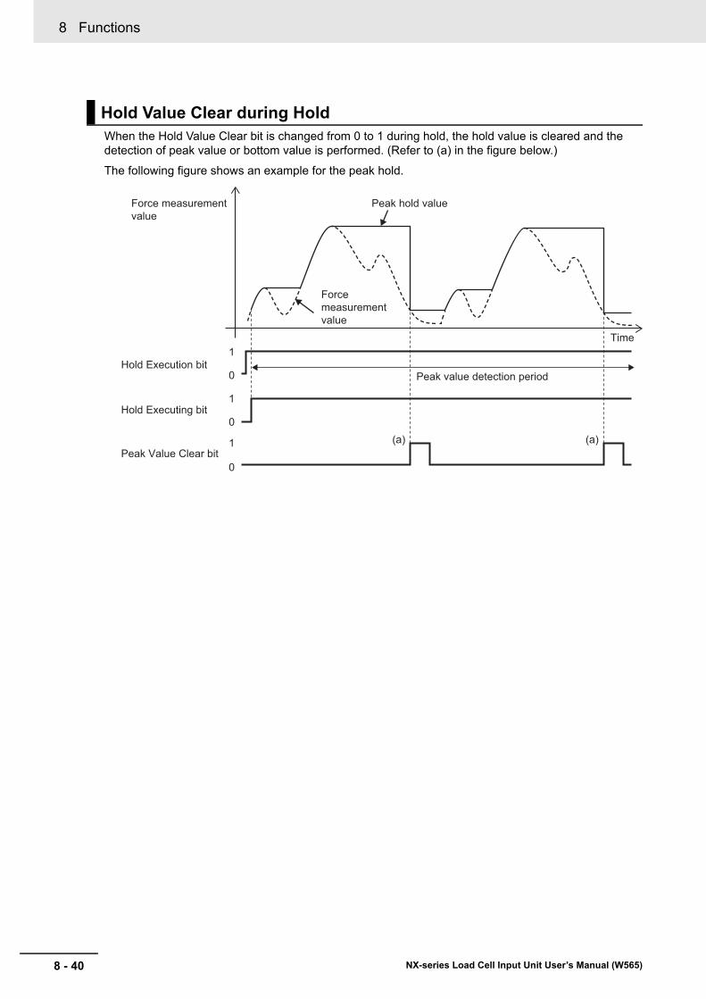
8 Functions
8 - 40 NX-series Load Cell Input Unit User’s Manual (W565)
When the Hold Value Clear bit is changed from 0 to 1 during hold, the hold value is cleared and the detection of peak value or bottom value is performed. (Refer to (a) in the figure below.)
The following figure shows an example for the peak hold.
Hold Value Clear during Hold
Peak Value Clear bit
Peak hold value
Peak value detection period
Force measurement value
0
1Hold Execution bit
0
1
0
1Hold Executing bit
Force measurement value
Time
(a) (a)
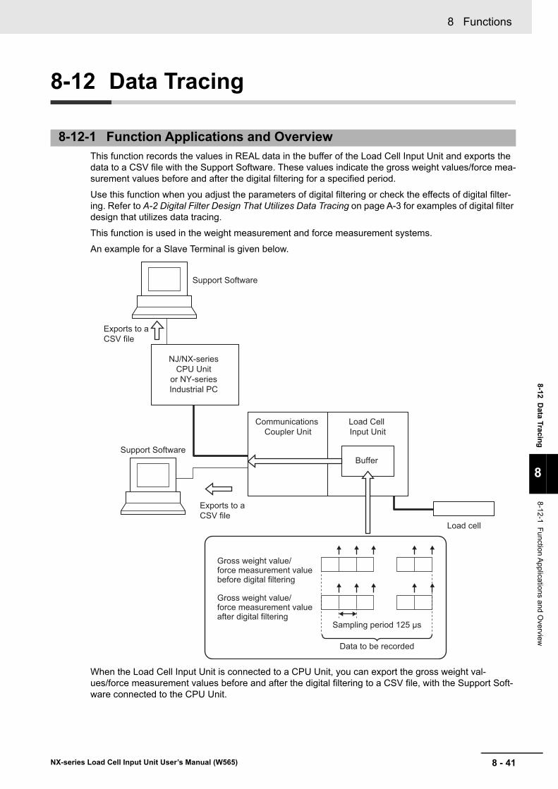
8 - 41
8 Functions
NX-series Load Cell Input Unit User’s Manual (W565)
8-12 D
ata Tracin
g
8
8-12-1 F
unction Applications a
nd Overview
8-12 Data Tracing
This function records the values in REAL data in the buffer of the Load Cell Input Unit and exports the data to a CSV file with the Support Software. These values indicate the gross weight values/force mea-surement values before and after the digital filtering for a specified period.
Use this function when you adjust the parameters of digital filtering or check the effects of digital filter-ing. Refer to A-2 Digital Filter Design That Utilizes Data Tracing on page A-3 for examples of digital filter design that utilizes data tracing.
This function is used in the weight measurement and force measurement systems.
An example for a Slave Terminal is given below.
When the Load Cell Input Unit is connected to a CPU Unit, you can export the gross weight val-ues/force measurement values before and after the digital filtering to a CSV file, with the Support Soft-ware connected to the CPU Unit.
8-12-1 Function Applications and Overview
Support Software
Support Software
Communications Coupler Unit
NJ/NX-series CPU Unit
or NY-series Industrial PC
Load Cell Input Unit
Buffer
Load cell
Sampling period 125 μs
Data to be recorded
Gross weight value/force measurement value after digital filtering
Gross weight value/force measurement value before digital filtering
Exports to a CSV file
Exports to a CSV file
8 Functions
8 - 42 NX-series Load Cell Input Unit User’s Manual (W565)
Specifications of Data Tracing
The specifications of data tracing is as follows.
Clearing and Overwriting the Tracing Data
When the power to the Unit is turned on or NX Unit is restarted, the tracing data is cleared.
If you terminate the data tracing and perform it again, the tracing data is cleared and overwritten with the data for which the data tracing is executed again.
How to Check the Tracing Result
You can use Support Software to check the tracing result by exporting the tracing data that is stored in the buffer of the Load Cell Input Unit to a CSV file. Refer to 8-12-4 How to Check the Tracing Result on page 8-45 for details on how to check the tracing results.
Precautions for Correct Use
• When the power supply to the Unit is turned on again or NX Unit is restarted, the tracing data is cleared. Pay attention that the data is removed and you cannot check it.
• If you terminate the data tracing and perform it again, the tracing data is cleared and overwrit-ten with the data for which the data tracing is executed again. Pay attention that you cannot check the previous data.
8-12-2 Details on the Function
Item Specification
Sampling period 125 µs
Recording data size • Gross weight values/force measurement values before filtering
80000 max.*1
• Gross weight values/force measurement values after filtering
80000 max.*1
*1. When the maximum recording data size is reached, data tracing is automatically ended.
Tracing data type REAL*2
*2. REAL data is recorded regardless of the assignment of the Gross Weight Value/Force Measurement Value DINT or Gross Weight Value/Force Measurement Value REAL of I/O data.
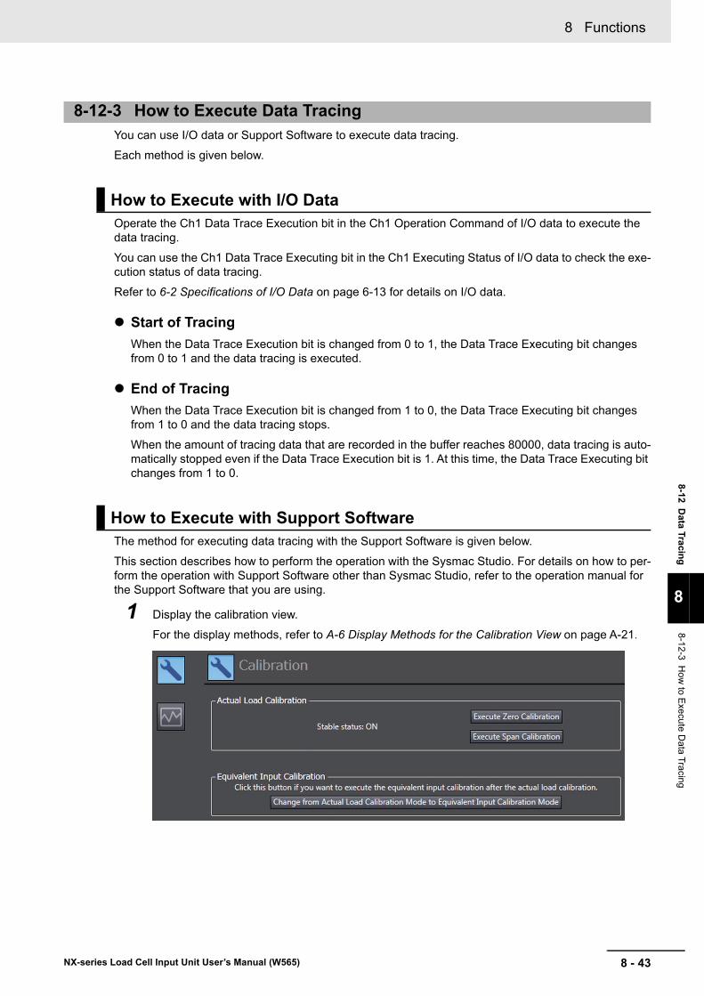
8 - 43
8 Functions
NX-series Load Cell Input Unit User’s Manual (W565)
8-12 D
ata Tracin
g
8
8-12-3 H
ow
to Exe
cute Data T
racing
You can use I/O data or Support Software to execute data tracing.
Each method is given below.
Operate the Ch1 Data Trace Execution bit in the Ch1 Operation Command of I/O data to execute the data tracing.
You can use the Ch1 Data Trace Executing bit in the Ch1 Executing Status of I/O data to check the exe-cution status of data tracing.
Refer to 6-2 Specifications of I/O Data on page 6-13 for details on I/O data.
Start of Tracing
When the Data Trace Execution bit is changed from 0 to 1, the Data Trace Executing bit changes from 0 to 1 and the data tracing is executed.
End of Tracing
When the Data Trace Execution bit is changed from 1 to 0, the Data Trace Executing bit changes from 1 to 0 and the data tracing stops.
When the amount of tracing data that are recorded in the buffer reaches 80000, data tracing is auto-matically stopped even if the Data Trace Execution bit is 1. At this time, the Data Trace Executing bit changes from 1 to 0.
The method for executing data tracing with the Support Software is given below.
This section describes how to perform the operation with the Sysmac Studio. For details on how to per-form the operation with Support Software other than Sysmac Studio, refer to the operation manual for the Support Software that you are using.
1 Display the calibration view.
For the display methods, refer to A-6 Display Methods for the Calibration View on page A-21.
8-12-3 How to Execute Data Tracing
How to Execute with I/O Data
How to Execute with Support Software
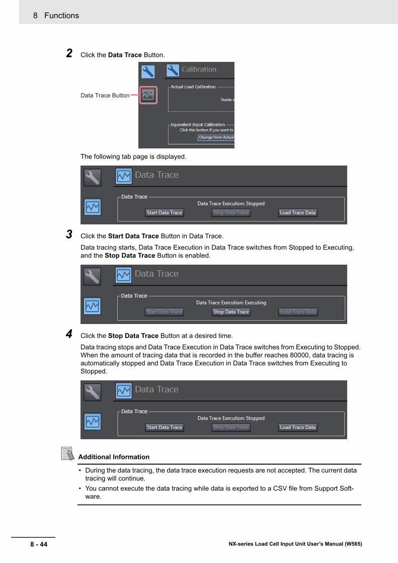
8 Functions
8 - 44 NX-series Load Cell Input Unit User’s Manual (W565)
2 Click the Data Trace Button.
The following tab page is displayed.
3 Click the Start Data Trace Button in Data Trace.
Data tracing starts, Data Trace Execution in Data Trace switches from Stopped to Executing, and the Stop Data Trace Button is enabled.
4 Click the Stop Data Trace Button at a desired time.
Data tracing stops and Data Trace Execution in Data Trace switches from Executing to Stopped. When the amount of tracing data that is recorded in the buffer reaches 80000, data tracing is automatically stopped and Data Trace Execution in Data Trace switches from Executing to Stopped.
Additional Information
• During the data tracing, the data trace execution requests are not accepted. The current data tracing will continue.
• You cannot execute the data tracing while data is exported to a CSV file from Support Soft-ware.
Data Trace Button
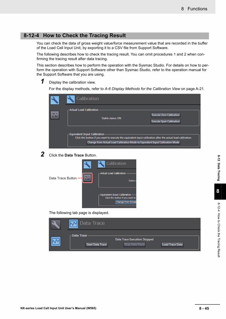
8 - 45
8 Functions
NX-series Load Cell Input Unit User’s Manual (W565)
8-12 D
ata Tracin
g
8
8-12-4 H
ow
to Check the T
racing R
esult
You can check the data of gross weight value/force measurement value that are recorded in the buffer of the Load Cell Input Unit, by exporting it to a CSV file from Support Software.
The following describes how to check the tracing result. You can omit procedures 1 and 2 when con-firming the tracing result after data tracing.
This section describes how to perform the operation with the Sysmac Studio. For details on how to per-form the operation with Support Software other than Sysmac Studio, refer to the operation manual for the Support Software that you are using.
1 Display the calibration view.
For the display methods, refer to A-6 Display Methods for the Calibration View on page A-21.
2 Click the Data Trace Button.
The following tab page is displayed.
8-12-4 How to Check the Tracing Result
Data Trace Button
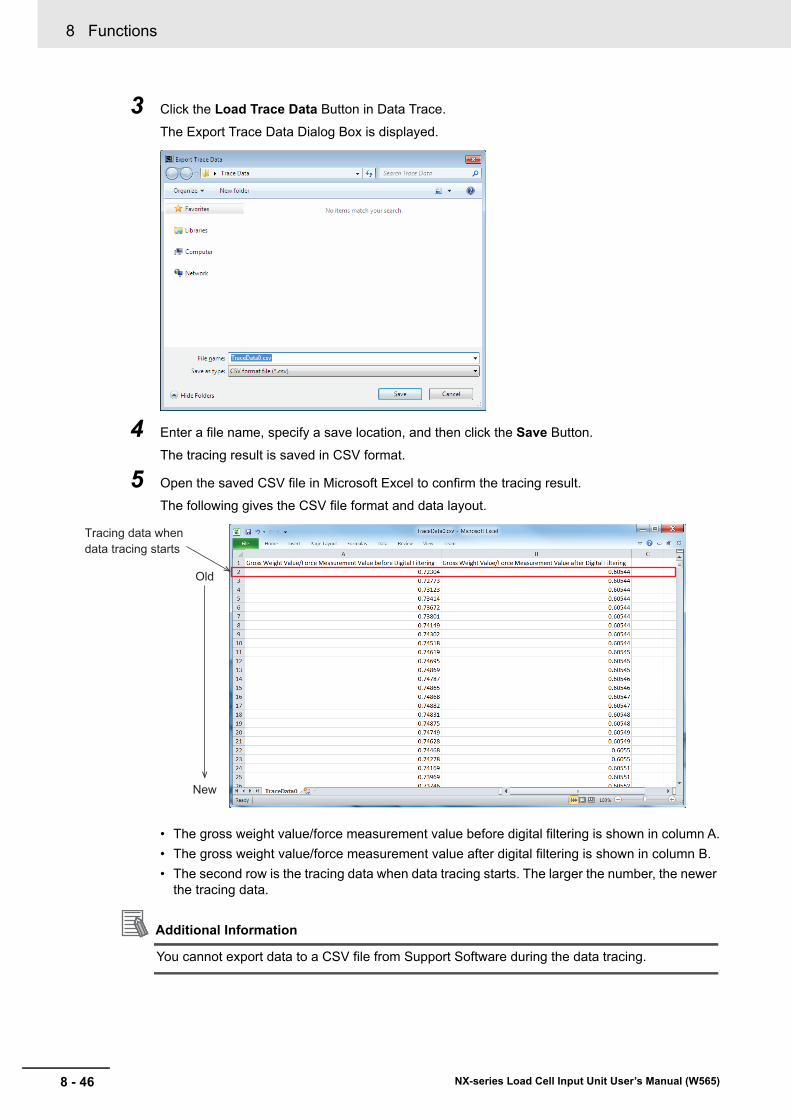
8 Functions
8 - 46 NX-series Load Cell Input Unit User’s Manual (W565)
3 Click the Load Trace Data Button in Data Trace.
The Export Trace Data Dialog Box is displayed.
4 Enter a file name, specify a save location, and then click the Save Button.
The tracing result is saved in CSV format.
5 Open the saved CSV file in Microsoft Excel to confirm the tracing result.
The following gives the CSV file format and data layout.
• The gross weight value/force measurement value before digital filtering is shown in column A.
• The gross weight value/force measurement value after digital filtering is shown in column B.
• The second row is the tracing data when data tracing starts. The larger the number, the newer the tracing data.
Additional Information
You cannot export data to a CSV file from Support Software during the data tracing.
Old
New
Tracing data when data tracing starts
8 - 47
8 Functions
NX-series Load Cell Input Unit User’s Manual (W565)
8-13 Decim
al Po
int P
os
ition
Settin
g
8
8-13-1 F
unction Applications a
nd Overview
8-13 Decimal Point Position Setting
This function sets the number of digits which is displayed after the decimal point for each DINT data.
This function is used in the weight measurement and force measurement systems.
After the measurement values in the Load Cell Input Unit are converted to REAL data, they are con-verted to DINT data.
During the conversion, DINT data are rounded following the number of digits after the decimal point, which was set by this function, and the rounded results become measurement values.
In the case of a REAL measurement value of 1.45454, for example, its DINT data value varies as fol-lows depending on the setting of the decimal point position.
Set the decimal point position for DINT data in the Unit operation settings. The settings are shown in the following table.
8-13-1 Function Applications and Overview
8-13-2 Details on the Function
Decimal point position DINT data value
0th decimal point 1
First decimal point 15
Second decimal point 145
Third decimal point 1455
Fourth decimal point 14545
Item Setting description Default Setting range Unit Remarks
Ch1 Deci-mal Point Position
Sets the decimal point position for Gross Weight Value/Force Measurement Value DINT, Net Weight Value DINT, Peak Hold Value DINT and Bottom Hold Value DINT.
0 0: × 100
1: × 101
2: × 102
3: × 103
4: × 104
--- Set values are applied when the power supply to the NX Unit is turned ON or the NX Unit is restarted.

8 Functions
8 - 48 NX-series Load Cell Input Unit User’s Manual (W565)
The method for setting the decimal point with the Support Software is given below.
This section describes how to configure settings with the Sysmac Studio. For details on how to config-ure settings with Support Software other than Sysmac Studio, refer to the operation manual for the Sup-port Software that you are using.
1 Double-click the target Load Cell Input Unit in the Multiview Explorer to open the Edit Unit Oper-ation Settings Tab Page.
The following tab page is displayed.
2 Set the Ch1 Decimal Point Position.
3 Click the Transfer to Unit Button.
The settings are transferred from the Support Software to the NX Unit.
The settings are reflected after the NX Unit is restarted.
Precautions for Safe Use
The Unit is required to restart after the transfer of Unit operation settings on the Support Soft-ware is completed. Always sufficiently check the safety at the connected devices before you transfer the Unit operation settings.
8-13-3 Setting Method
9 - 1
9
NX-series Load Cell Input Unit User’s Manual (W565)
This section describes the error information and corrections for errors that can occur when the Load Cell Input Unit is used.
9-1 How to Check for Errors . . . . . . . . . . . . . . . . . . . . . . . . . . . . . . . . . . . . . . . . 9-2
9-2 Checking for Errors with the Indicators . . . . . . . . . . . . . . . . . . . . . . . . . . . . 9-3
9-3 Checking for Errors and Troubleshooting on the Support Software . . . . 9-59-3-1 Checking for Errors from the Sysmac Studio . . . . . . . . . . . . . . . . . . . . . . . . . . 9-5
9-3-2 Checking for Errors from Support Software Other Than the Sysmac Studio . . 9-6
9-3-3 Event Codes and Corrections for Errors . . . . . . . . . . . . . . . . . . . . . . . . . . . . . . 9-6
9-3-4 Meaning of Error . . . . . . . . . . . . . . . . . . . . . . . . . . . . . . . . . . . . . . . . . . . . . . . 9-10
9-4 Resetting Errors . . . . . . . . . . . . . . . . . . . . . . . . . . . . . . . . . . . . . . . . . . . . . . 9-26
9-5 Unit-specific Troubleshooting . . . . . . . . . . . . . . . . . . . . . . . . . . . . . . . . . . 9-27
9-6 Measurement Values Used When an Error Occurs . . . . . . . . . . . . . . . . . . 9-30
9-7 Troubleshooting Flowchart . . . . . . . . . . . . . . . . . . . . . . . . . . . . . . . . . . . . . 9-31
Troubleshooting
9 Troubleshooting
9 - 2 NX-series Load Cell Input Unit User’s Manual (W565)
9-1 How to Check for Errors
Use one of the following error checking methods.
• Checking the indicators
• Troubleshooting with the Support Software
Refer to the user’s manual for the connected CPU Unit or Communications Coupler Unit for information on checking errors with the troubleshooting functions of the Support Software.
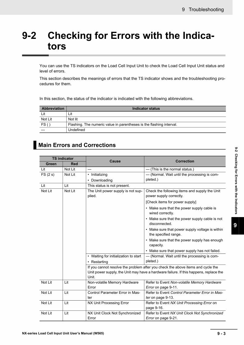
9 - 3
9 Troubleshooting
NX-series Load Cell Input Unit User’s Manual (W565)
9-2 Ch
ecking
for E
rrors w
ith th
e In
dicato
rs
9
9-2 Checking for Errors with the Indica-tors
You can use the TS indicators on the Load Cell Input Unit to check the Load Cell Input Unit status and level of errors.
This section describes the meanings of errors that the TS indicator shows and the troubleshooting pro-cedures for them.
In this section, the status of the indicator is indicated with the following abbreviations.
Abbreviation Indicator status
Lit Lit
Not Lit Not lit
FS ( ) Flashing. The numeric value in parentheses is the flashing interval.
--- Undefined
Main Errors and Corrections
TS indicatorCause Correction
Green Red
Lit Not Lit --- --- (This is the normal status.)
FS (2 s) Not Lit • Initializing
• Downloading
--- (Normal. Wait until the processing is com-pleted.)
Lit Lit This status is not present.
Not Lit Not Lit The Unit power supply is not sup-plied.
Check the following items and supply the Unit power supply correctly.
[Check items for power supply]
• Make sure that the power supply cable is wired correctly.
• Make sure that the power supply cable is not disconnected.
• Make sure that power supply voltage is within the specified range.
• Make sure that the power supply has enough capacity.
• Make sure that power supply has not failed.
• Waiting for initialization to start
• Restarting
--- (Normal. Wait until the processing is com-pleted.)
If you cannot resolve the problem after you check the above items and cycle the Unit power supply, the Unit may have a hardware failure. If this happens, replace the Unit.
Not Lit Lit Non-volatile Memory Hardware Error
Refer to Event Non-volatile Memory Hardware Error on page 9-11.
Not Lit Lit Control Parameter Error in Mas-ter
Refer to Event Control Parameter Error in Mas-ter on page 9-13.
Not Lit Lit NX Unit Processing Error Refer to Event NX Unit Processing Error on page 9-16.
Not Lit Lit NX Unit Clock Not Synchronized Error
Refer to Event NX Unit Clock Not Synchronized Error on page 9-21.
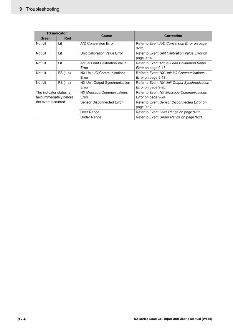
9 Troubleshooting
9 - 4 NX-series Load Cell Input Unit User’s Manual (W565)
Not Lit Lit A/D Conversion Error Refer to Event A/D Conversion Error on page 9-12.
Not Lit Lit Unit Calibration Value Error Refer to Event Unit Calibration Value Error on page 9-14.
Not Lit Lit Actual Load Calibration Value Error
Refer to Event Actual Load Calibration Value Error on page 9-15.
Not Lit FS (1 s) NX Unit I/O Communications Error
Refer to Event NX Unit I/O Communications Error on page 9-18.
Not Lit FS (1 s) NX Unit Output Synchronization Error
Refer to Event NX Unit Output Synchronization Error on page 9-20.
The indicator status is held immediately before the event occurred.
NX Message Communications Error
Refer to Event NX Message Communications Error on page 9-24.
Sensor Disconnected Error Refer to Event Sensor Disconnected Error on page 9-17.
Over Range Refer to Event Over Range on page 9-22.
Under Range Refer to Event Under Range on page 9-23.
TS indicatorCause Correction
Green Red
9 - 5
9 Troubleshooting
NX-series Load Cell Input Unit User’s Manual (W565)
9-3 Ch
ecking
for E
rrors an
d Tro
ub
lesho
otin
g o
n th
e Su
pp
ort S
oftw
are
9
9-3-1 Checking for E
rrors from the S
ysmac S
tudio
9-3 Checking for Errors and Trouble-shooting on the Support Software
Error management on the NX Series is based on the methods used for the NJ/NX/NY-series Control-lers.
This allows you to use the Support Software to check the meanings of errors and troubleshooting pro-cedures. The confirmation method depends on the Support Software.
When an error occurs, you can place the Sysmac Studio online to the Controller or the Communications Coupler Unit to check current Controller errors and the log of past Controller errors.
Refer to the user’s manual for the connected CPU Unit or Communications Coupler Unit for details on how to check errors.
Open the Sysmac Studio's Controller Error Tab Page to check the current error's level, source,
source details, event name, event codes, details, attached information 1 to 4, and correction.
Errors in the observation level are not displayed.
Additional Information
Number of Current Errors
The following table gives the number of errors that are reported simultaneously as current errors in the Load Cell Input Unit.
If the number of errors exceeds the maximum number of reportable current errors, errors are reported with a priority given to the oldest and highest-level errors. Errors that exceed the limit on simultaneous error notifications are not reported.
Errors that are not reported are still reflected in the error status.
9-3-1 Checking for Errors from the Sysmac Studio
Current Errors
Unit Number of simultaneous error notifications
Load Cell Input Unit 15 errors
9 Troubleshooting
9 - 6 NX-series Load Cell Input Unit User’s Manual (W565)
Open the Sysmac Studio's Controller Event Log Tab Page to check the times, levels, sources, source details, event names, event codes, details, attached information 1 to 4, and corrections for previous errors.
Additional Information
Number of Logs of Past Errors
Event logs in the Load Cell Input Unit are stored in the Load Cell Input Unit itself.
The system event log can record 15 events. The access event log can record 2 events.
Refer to the troubleshooting manual for the connected CPU Unit or Industrial PC and the Sysmac Studio Version 1 Operation Manual (Cat. No. W504) for the items that you can check and the procedures to check for errors.Refer to 9-3-3 Event Codes and Corrections for Errors on page 9-6 for details on event codes.
You can check the error descriptions and logs with Support Software other than the Sysmac Studio. For the error checking methods, refer to the user’s manual for the connected Communications Coupler Unit and the operation manual for the Support Software.
Refer to 9-3-3 Event Codes and Corrections for Errors on page 9-6 for details on event codes.
The number of current errors and the number of error log errors that occurred in the past are the same as for the Sysmac Studio.
The errors (i.e.,events) that occur in the Load Cell Input Unit is given below.
The following abbreviations are used in the event level column.
Refer to the troubleshooting manual for the connected CPU Unit or Industrial PC for information on NJ/NX/NY-series event codes.
Log of Past Errors
9-3-2 Checking for Errors from Support Software Other Than the Sysmac Studio
9-3-3 Event Codes and Corrections for Errors
Abbreviation Name
Maj Major fault level
Prt Partial fault level
Min Minor fault level
Obs Observation
Info Information
Symbol Meaning
S Event levels that are defined by the system.
U Event levels that can be changed by the user. *1
*1. This symbol appears only for events for which the user can change the event level.
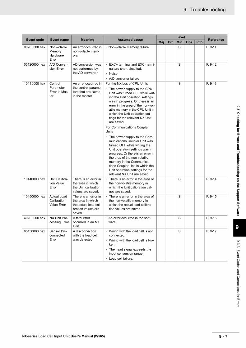
9 - 7
9 Troubleshooting
NX-series Load Cell Input Unit User’s Manual (W565)
9-3 Ch
ecking
for E
rrors an
d Tro
ub
lesho
otin
g o
n th
e Su
pp
ort S
oftw
are
9
9-3-3 Event C
odes and Corre
ctions for Errors
Event code Event name Meaning Assumed causeLevel
ReferenceMaj Prt Min Obs Info
00200000 hex Non-volatile Memory Hardware Error
An error occurred in non-volatile mem-ory.
• Non-volatile memory failure S P. 9-11
05120000 hex A/D Conver-sion Error
AD conversion was not performed by the AD converter.
• EXC+ terminal and EXC- termi-nal are short-circuited.
• Noise
• A/D converter failure
S P. 9-12
10410000 hex Control Parameter Error in Mas-ter
An error occurred in the control parame-ters that are saved in the master.
For the NX bus of CPU Units
• The power supply to the CPU Unit was turned OFF while writ-ing the Unit operation settings was in progress. Or there is an error in the area of the non-vol-atile memory in the CPU Unit in which the Unit operation set-tings for the relevant NX Unit are saved.
For Communications Coupler Units
• The power supply to the Com-munications Coupler Unit was turned OFF while writing the Unit operation settings was in progress. Or there is an error in the area of the non-volatile memory in the Communica-tions Coupler Unit in which the Unit operation settings for the relevant NX Unit are saved.
S P. 9-13
10440000 hex Unit Calibra-tion Value Error
There is an error in the area in which the Unit calibration values are saved.
• There is an error in the area of the non-volatile memory in which the Unit calibration val-ues are saved.
S P. 9-14
10450000 hex Actual Load Calibration Value Error
There is an error in the area in which the actual load cali-bration values are saved.
• There is an error in the area of the non-volatile memory in which the actual load calibra-tion values are saved.
S P. 9-15
40200000 hex NX Unit Pro-cessing Error
A fatal error occurred in an NX Unit.
• An error occurred in the soft-ware.
S P. 9-16
65130000 hex Sensor Dis-connected Error
A disconnection with the load cell was detected.
• Wiring with the load cell is not connected.
• Wiring with the load cell is bro-ken.
• The input signal exceeds the input conversion range.
• Load cell failure.
S P. 9-17
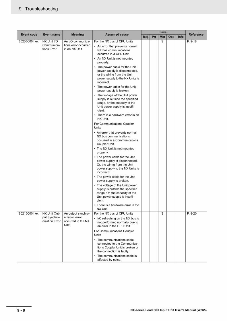
9 Troubleshooting
9 - 8 NX-series Load Cell Input Unit User’s Manual (W565)
80200000 hex NX Unit I/O Communica-tions Error
An I/O communica-tions error occurred in an NX Unit.
For the NX bus of CPU Units
• An error that prevents normal NX bus communications occurred in a CPU Unit.
• An NX Unit is not mounted properly.
• The power cable for the Unit power supply is disconnected, or the wiring from the Unit power supply to the NX Units is incorrect.
• The power cable for the Unit power supply is broken.
• The voltage of the Unit power supply is outside the specified range, or the capacity of the Unit power supply is insuffi-cient.
• There is a hardware error in an NX Unit.
For Communications Coupler Units
• An error that prevents normal NX bus communications occurred in a Communications Coupler Unit.
• The NX Unit is not mounted properly.
• The power cable for the Unit power supply is disconnected. Or, the wiring from the Unit power supply to the NX Units is incorrect.
• The power cable for the Unit power supply is broken.
• The voltage of the Unit power supply is outside the specified range. Or, the capacity of the Unit power supply is insuffi-cient.
• There is a hardware error in the NX Unit.
S P. 9-18
80210000 hex NX Unit Out-put Synchro-nization Error
An output synchro-nization error occurred in the NX Unit.
For the NX bus of CPU Units
• I/O refreshing on the NX bus is not performed normally due to an error in the CPU Unit.
For Communications Coupler Units
• The communications cable connected to the Communica-tions Coupler Unit is broken or the connection is faulty.
• The communications cable is affected by noise.
S P. 9-20
Event code Event name Meaning Assumed causeLevel
ReferenceMaj Prt Min Obs Info
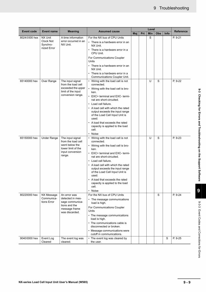
9 - 9
9 Troubleshooting
NX-series Load Cell Input Unit User’s Manual (W565)
9-3 Ch
ecking
for E
rrors an
d Tro
ub
lesho
otin
g o
n th
e Su
pp
ort S
oftw
are
9
9-3-3 Event C
odes and Corre
ctions for Errors
80240000 hex NX Unit Clock Not Synchro-nized Error
A time information error occurred in an NX Unit.
For the NX bus of CPU Units
• There is a hardware error in an NX Unit.
• There is a hardware error in a CPU Unit.
For Communications Coupler Units
• There is a hardware error in an NX Unit.
• There is a hardware error in a Communications Coupler Unit.
S P. 9-21
65140000 hex Over Range The input signal from the load cell exceeded the upper limit of the input conversion range.
• Wiring with the load cell is not connected.
• Wiring with the load cell is bro-ken.
• EXC+ terminal and EXC- termi-nal are short-circuited.
• Load cell failure.
• A load cell with which the rated output exceeds the input range of the Load Cell Input Unit is used.
• A load that exceeds the rated capacity is applied to the load cell.
• Noise
U S P. 9-22
65150000 hex Under Range The input signal from the load cell went below the lower limit of the input conversion range.
• Wiring with the load cell is not connected.
• Wiring with the load cell is bro-ken.
• EXC+ terminal and EXC- termi-nal are short-circuited.
• Load cell failure.
• A load cell with which the rated output exceeds the input range of the Load Cell Input Unit is used.
• A load that exceeds the rated capacity is applied to the load cell.
• Noise
U S P. 9-23
80220000 hex NX Message Communica-tions Error
An error was detected in mes-sage communica-tions and the message frame was discarded.
For the NX bus of CPU Units
• The message communications load is high.
For Communications Coupler Units
• The message communications load is high.
• The communications cable is disconnected or broken.
• Message communications were cutoff in communications.
S P. 9-24
90400000 hex Event Log Cleared
The event log was cleared.
• The event log was cleared by the user.
S P. 9-25
Event code Event name Meaning Assumed causeLevel
ReferenceMaj Prt Min Obs Info
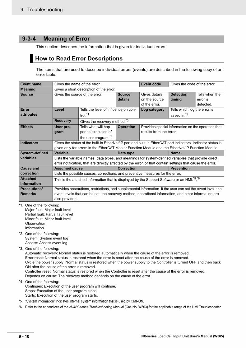
9 Troubleshooting
9 - 10 NX-series Load Cell Input Unit User’s Manual (W565)
This section describes the information that is given for individual errors.
The items that are used to describe individual errors (events) are described in the following copy of an error table.
9-3-4 Meaning of Error
How to Read Error Descriptions
Event name Gives the name of the error. Event code Gives the code of the error.Meaning Gives a short description of the error.Source Gives the source of the error. Source
detailsGives details on the source of the error.
Detection timing
Tells when the error is detected.
Error attributes
Level Tells the level of influence on con-
trol.*1
*1. One of the following:Major fault: Major fault levelPartial fault: Partial fault levelMinor fault: Minor fault levelObservationInformation
Log category Tells which log the error is
saved in.*2
*2. One of the following:System: System event logAccess: Access event log
Recovery Gives the recovery method.*3
*3. One of the following:Automatic recovery: Normal status is restored automatically when the cause of the error is removed.Error reset: Normal status is restored when the error is reset after the cause of the error is removed.Cycle the power supply: Normal status is restored when the power supply to the Controller is turned OFF and then back ON after the cause of the error is removed.Controller reset: Normal status is restored when the Controller is reset after the cause of the error is removed.Depends on cause: The recovery method depends on the cause of the error.
Effects User pro-gram
Tells what will hap-pen to execution of
the user program.*4
*4. One of the following:Continues: Execution of the user program will continue.Stops: Execution of the user program stops.Starts: Execution of the user program starts.
Operation Provides special information on the operation that results from the error.
Indicators Gives the status of the built-in EtherNet/IP port and built-in EtherCAT port indicators. Indicator status is given only for errors in the EtherCAT Master Function Module and the EtherNet/IP Function Module.
System-defined variables
Variable Data type NameLists the variable names, data types, and meanings for system-defined variables that provide direct error notification, that are directly affected by the error, or that contain settings that cause the error.
Cause and correction
Assumed cause Correction PreventionLists the possible causes, corrections, and preventive measures for the error.
Attached information
This is the attached information that is displayed by the Support Software or an HMI.*5,*6
*5. “System information” indicates internal system information that is used by OMRON.
*6. Refer to the appendices of the NJ/NX-series Troubleshooting Manual (Cat. No. W503) for the applicable range of the HMI Troubleshooter.
Precautions/Remarks
Provides precautions, restrictions, and supplemental information. If the user can set the event level, the event levels that can be set, the recovery method, operational information, and other information are also provided.
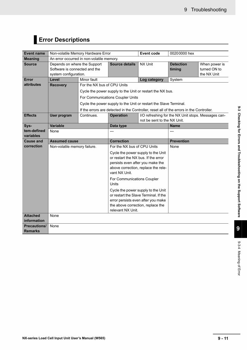
9 - 11
9 Troubleshooting
NX-series Load Cell Input Unit User’s Manual (W565)
9-3 Ch
ecking
for E
rrors an
d Tro
ub
lesho
otin
g o
n th
e Su
pp
ort S
oftw
are
9
9-3-4 Meaning of E
rror
Error Descriptions
Event name Non-volatile Memory Hardware Error Event code 00200000 hex
Meaning An error occurred in non-volatile memory.
Source Depends on where the Support Software is connected and the system configuration.
Source details NX Unit Detection timing
When power is turned ON to the NX Unit
Error attributes
Level Minor fault Log category System
Recovery For the NX bus of CPU Units
Cycle the power supply to the Unit or restart the NX bus.
For Communications Coupler Units
Cycle the power supply to the Unit or restart the Slave Terminal.
If the errors are detected in the Controller, reset all of the errors in the Controller.
Effects User program Continues. Operation I/O refreshing for the NX Unit stops. Messages can-not be sent to the NX Unit.
Sys-tem-defined variables
Variable Data type Name
None --- ---
Cause and correction
Assumed cause Correction Prevention
Non-volatile memory failure. For the NX bus of CPU Units
Cycle the power supply to the Unit or restart the NX bus. If the error persists even after you make the above correction, replace the rele-vant NX Unit.
For Communications Coupler Units
Cycle the power supply to the Unit or restart the Slave Terminal. If the error persists even after you make the above correction, replace the relevant NX Unit.
None
Attached information
None
Precautions/Remarks
None
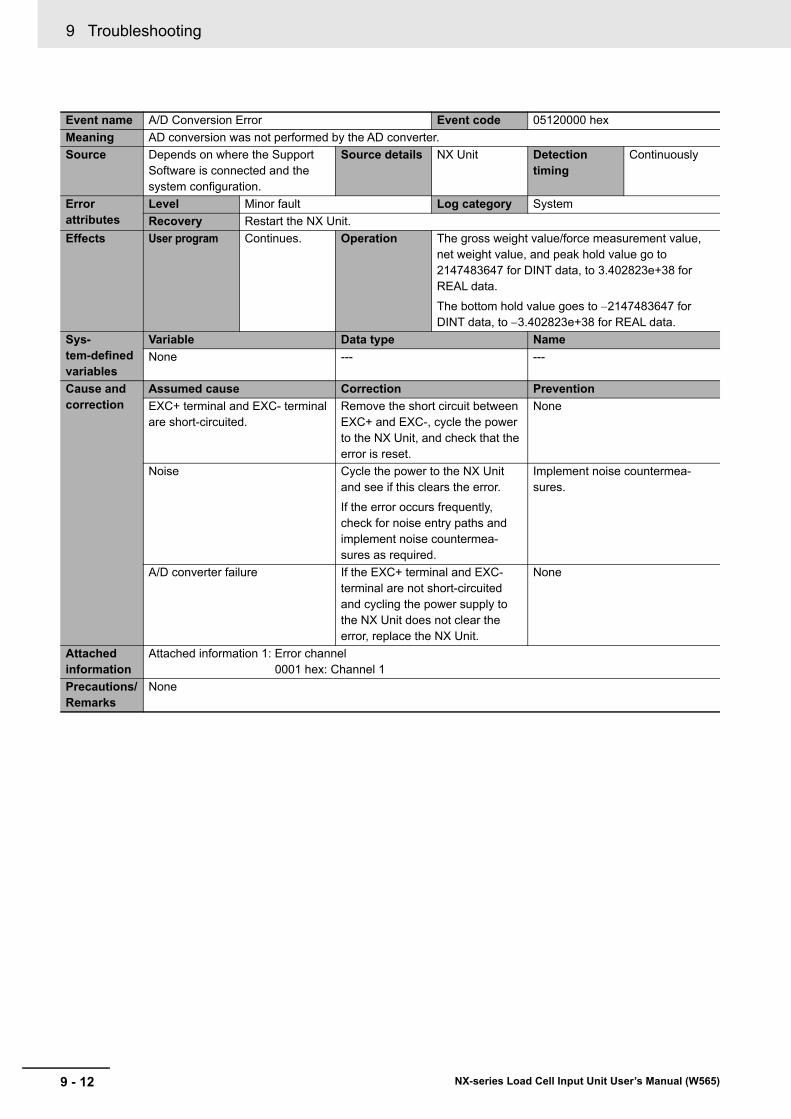
9 Troubleshooting
9 - 12 NX-series Load Cell Input Unit User’s Manual (W565)
Event name A/D Conversion Error Event code 05120000 hex
Meaning AD conversion was not performed by the AD converter.
Source Depends on where the Support Software is connected and the system configuration.
Source details NX Unit Detection timing
Continuously
Error attributes
Level Minor fault Log category System
Recovery Restart the NX Unit.
Effects User program Continues. Operation The gross weight value/force measurement value, net weight value, and peak hold value go to 2147483647 for DINT data, to 3.402823e+38 for REAL data.
The bottom hold value goes to 2147483647 for DINT data, to 3.402823e+38 for REAL data.
Sys-tem-defined variables
Variable Data type Name
None --- ---
Cause and correction
Assumed cause Correction Prevention
EXC+ terminal and EXC- terminal are short-circuited.
Remove the short circuit between EXC+ and EXC-, cycle the power to the NX Unit, and check that the error is reset.
None
Noise Cycle the power to the NX Unit and see if this clears the error.
If the error occurs frequently, check for noise entry paths and implement noise countermea-sures as required.
Implement noise countermea-sures.
A/D converter failure If the EXC+ terminal and EXC- terminal are not short-circuited and cycling the power supply to the NX Unit does not clear the error, replace the NX Unit.
None
Attached information
Attached information 1: Error channel0001 hex: Channel 1
Precautions/Remarks
None
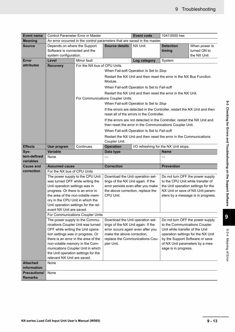
9 - 13
9 Troubleshooting
NX-series Load Cell Input Unit User’s Manual (W565)
9-3 Ch
ecking
for E
rrors an
d Tro
ub
lesho
otin
g o
n th
e Su
pp
ort S
oftw
are
9
9-3-4 Meaning of E
rror
Event name Control Parameter Error in Master Event code 10410000 hex
Meaning An error occurred in the control parameters that are saved in the master.
Source Depends on where the Support Software is connected and the system configuration.
Source details NX Unit Detection timing
When power is turned ON to the NX Unit
Error attributes
Level Minor fault Log category System
Recovery For the NX bus of CPU Units
When Fail-soft Operation Is Set to Stop
Restart the NX Unit and then reset the error in the NX Bus Function Module.
When Fail-soft Operation Is Set to Fail-soft
Restart the NX Unit and then reset the error in the NX Unit.
For Communications Coupler Units
When Fail-soft Operation Is Set to Stop
If the errors are detected in the Controller, restart the NX Unit and then reset all of the errors in the Controller.
If the errors are not detected in the Controller, restart the NX Unit and then reset the error in the Communications Coupler Unit.
When Fail-soft Operation Is Set to Fail-soft
Restart the NX Unit and then reset the error in the Communications Coupler Unit.
Effects User program Continues. Operation I/O refreshing for the NX Unit stops.
Sys-tem-defined variables
Variable Data type Name
None --- ---
Cause and correction
Assumed cause Correction Prevention
For the NX bus of CPU Units
The power supply to the CPU Unit was turned OFF while writing the Unit operation settings was in progress. Or there is an error in the area of the non-volatile mem-ory in the CPU Unit in which the Unit operation settings for the rel-evant NX Unit are saved.
Download the Unit operation set-tings of the NX Unit again. If the error persists even after you make the above correction, replace the CPU Unit.
Do not turn OFF the power supply to the CPU Unit while transfer of the Unit operation settings for the NX Unit or save of NX Unit param-eters by a message is in progress.
For Communications Coupler Units
The power supply to the Commu-nications Coupler Unit was turned OFF while writing the Unit opera-tion settings was in progress. Or there is an error in the area of the non-volatile memory in the Com-munications Coupler Unit in which the Unit operation settings for the relevant NX Unit are saved.
Download the Unit operation set-tings of the NX Unit again. If the error occurs again even after you make the above correction, replace the Communications Cou-pler Unit.
Do not turn OFF the power supply to the Communications Coupler Unit while transfer of the Unit operation settings for the NX Unit by the Support Software or save of NX Unit parameters by a mes-sage is in progress.
Attached information
None
Precautions/Remarks
None
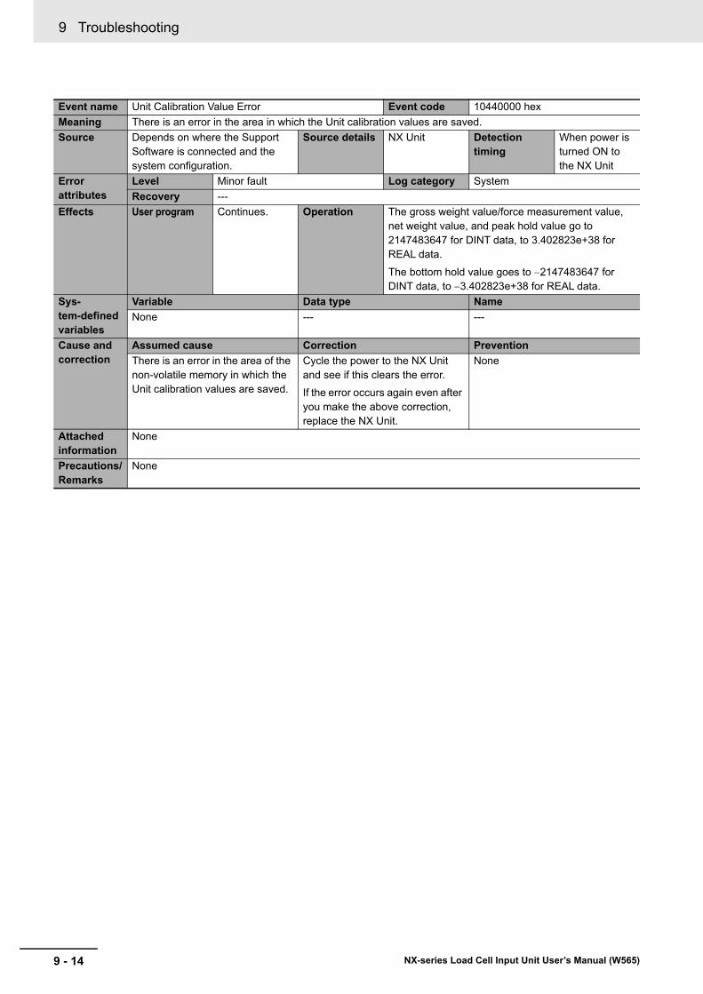
9 Troubleshooting
9 - 14 NX-series Load Cell Input Unit User’s Manual (W565)
Event name Unit Calibration Value Error Event code 10440000 hex
Meaning There is an error in the area in which the Unit calibration values are saved.
Source Depends on where the Support Software is connected and the system configuration.
Source details NX Unit Detection timing
When power is turned ON to the NX Unit
Error attributes
Level Minor fault Log category System
Recovery ---
Effects User program Continues. Operation The gross weight value/force measurement value, net weight value, and peak hold value go to 2147483647 for DINT data, to 3.402823e+38 for REAL data.
The bottom hold value goes to 2147483647 for DINT data, to 3.402823e+38 for REAL data.
Sys-tem-defined variables
Variable Data type Name
None --- ---
Cause and correction
Assumed cause Correction Prevention
There is an error in the area of the non-volatile memory in which the Unit calibration values are saved.
Cycle the power to the NX Unit and see if this clears the error.
If the error occurs again even after you make the above correction, replace the NX Unit.
None
Attached information
None
Precautions/Remarks
None
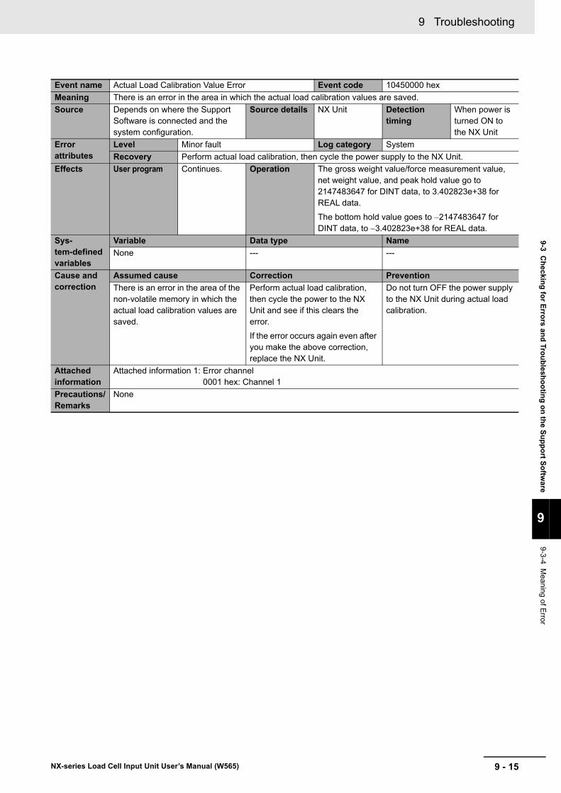
9 - 15
9 Troubleshooting
NX-series Load Cell Input Unit User’s Manual (W565)
9-3 Ch
ecking
for E
rrors an
d Tro
ub
lesho
otin
g o
n th
e Su
pp
ort S
oftw
are
9
9-3-4 Meaning of E
rror
Event name Actual Load Calibration Value Error Event code 10450000 hex
Meaning There is an error in the area in which the actual load calibration values are saved.
Source Depends on where the Support Software is connected and the system configuration.
Source details NX Unit Detection timing
When power is turned ON to the NX Unit
Error attributes
Level Minor fault Log category System
Recovery Perform actual load calibration, then cycle the power supply to the NX Unit.
Effects User program Continues. Operation The gross weight value/force measurement value, net weight value, and peak hold value go to 2147483647 for DINT data, to 3.402823e+38 for REAL data.
The bottom hold value goes to 2147483647 for DINT data, to 3.402823e+38 for REAL data.
Sys-tem-defined variables
Variable Data type Name
None --- ---
Cause and correction
Assumed cause Correction Prevention
There is an error in the area of the non-volatile memory in which the actual load calibration values are saved.
Perform actual load calibration, then cycle the power to the NX Unit and see if this clears the error.
If the error occurs again even after you make the above correction, replace the NX Unit.
Do not turn OFF the power supply to the NX Unit during actual load calibration.
Attached information
Attached information 1: Error channel0001 hex: Channel 1
Precautions/Remarks
None
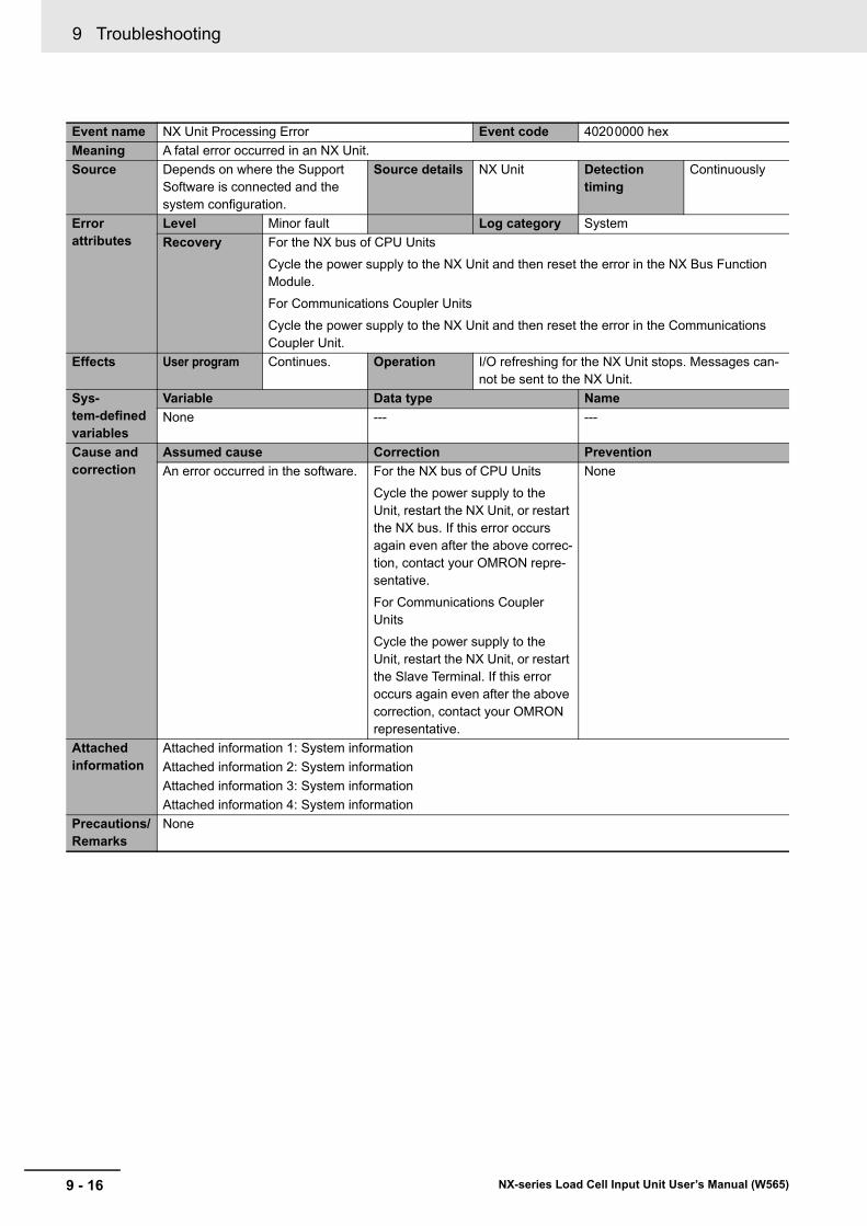
9 Troubleshooting
9 - 16 NX-series Load Cell Input Unit User’s Manual (W565)
Event name NX Unit Processing Error Event code 40200000 hex
Meaning A fatal error occurred in an NX Unit.
Source Depends on where the Support Software is connected and the system configuration.
Source details NX Unit Detection timing
Continuously
Error attributes
Level Minor fault Log category System
Recovery For the NX bus of CPU Units
Cycle the power supply to the NX Unit and then reset the error in the NX Bus Function Module.
For Communications Coupler Units
Cycle the power supply to the NX Unit and then reset the error in the Communications Coupler Unit.
Effects User program Continues. Operation I/O refreshing for the NX Unit stops. Messages can-not be sent to the NX Unit.
Sys-tem-defined variables
Variable Data type Name
None --- ---
Cause and correction
Assumed cause Correction Prevention
An error occurred in the software. For the NX bus of CPU Units
Cycle the power supply to the Unit, restart the NX Unit, or restart the NX bus. If this error occurs again even after the above correc-tion, contact your OMRON repre-sentative.
For Communications Coupler Units
Cycle the power supply to the Unit, restart the NX Unit, or restart the Slave Terminal. If this error occurs again even after the above correction, contact your OMRON representative.
None
Attached information
Attached information 1: System information
Attached information 2: System information
Attached information 3: System information
Attached information 4: System information
Precautions/Remarks
None
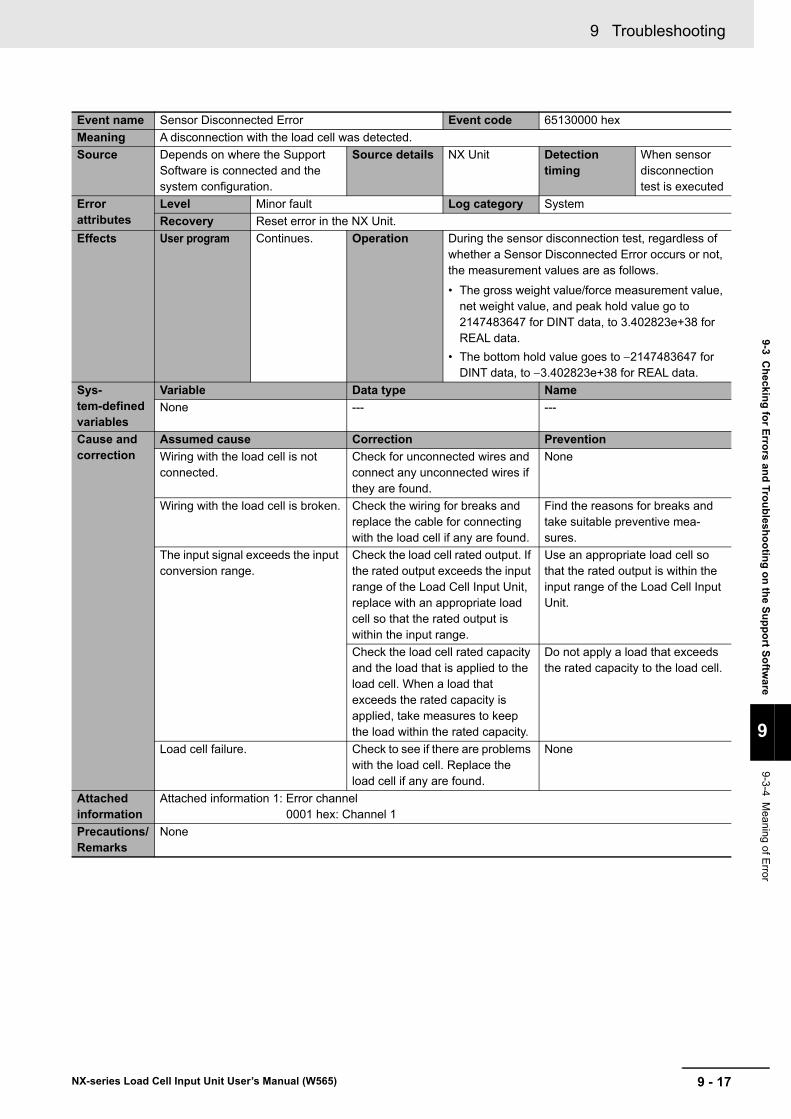
9 - 17
9 Troubleshooting
NX-series Load Cell Input Unit User’s Manual (W565)
9-3 Ch
ecking
for E
rrors an
d Tro
ub
lesho
otin
g o
n th
e Su
pp
ort S
oftw
are
9
9-3-4 Meaning of E
rror
Event name Sensor Disconnected Error Event code 65130000 hex
Meaning A disconnection with the load cell was detected.
Source Depends on where the Support Software is connected and the system configuration.
Source details NX Unit Detection timing
When sensor disconnection test is executed
Error attributes
Level Minor fault Log category System
Recovery Reset error in the NX Unit.
Effects User program Continues. Operation During the sensor disconnection test, regardless of whether a Sensor Disconnected Error occurs or not, the measurement values are as follows.
• The gross weight value/force measurement value, net weight value, and peak hold value go to 2147483647 for DINT data, to 3.402823e+38 for REAL data.
• The bottom hold value goes to 2147483647 for DINT data, to 3.402823e+38 for REAL data.
Sys-tem-defined variables
Variable Data type Name
None --- ---
Cause and correction
Assumed cause Correction Prevention
Wiring with the load cell is not connected.
Check for unconnected wires and connect any unconnected wires if they are found.
None
Wiring with the load cell is broken. Check the wiring for breaks and replace the cable for connecting with the load cell if any are found.
Find the reasons for breaks and take suitable preventive mea-sures.
The input signal exceeds the input conversion range.
Check the load cell rated output. If the rated output exceeds the input range of the Load Cell Input Unit, replace with an appropriate load cell so that the rated output is within the input range.
Use an appropriate load cell so that the rated output is within the input range of the Load Cell Input Unit.
Check the load cell rated capacity and the load that is applied to the load cell. When a load that exceeds the rated capacity is applied, take measures to keep the load within the rated capacity.
Do not apply a load that exceeds the rated capacity to the load cell.
Load cell failure. Check to see if there are problems with the load cell. Replace the load cell if any are found.
None
Attached information
Attached information 1: Error channel0001 hex: Channel 1
Precautions/Remarks
None
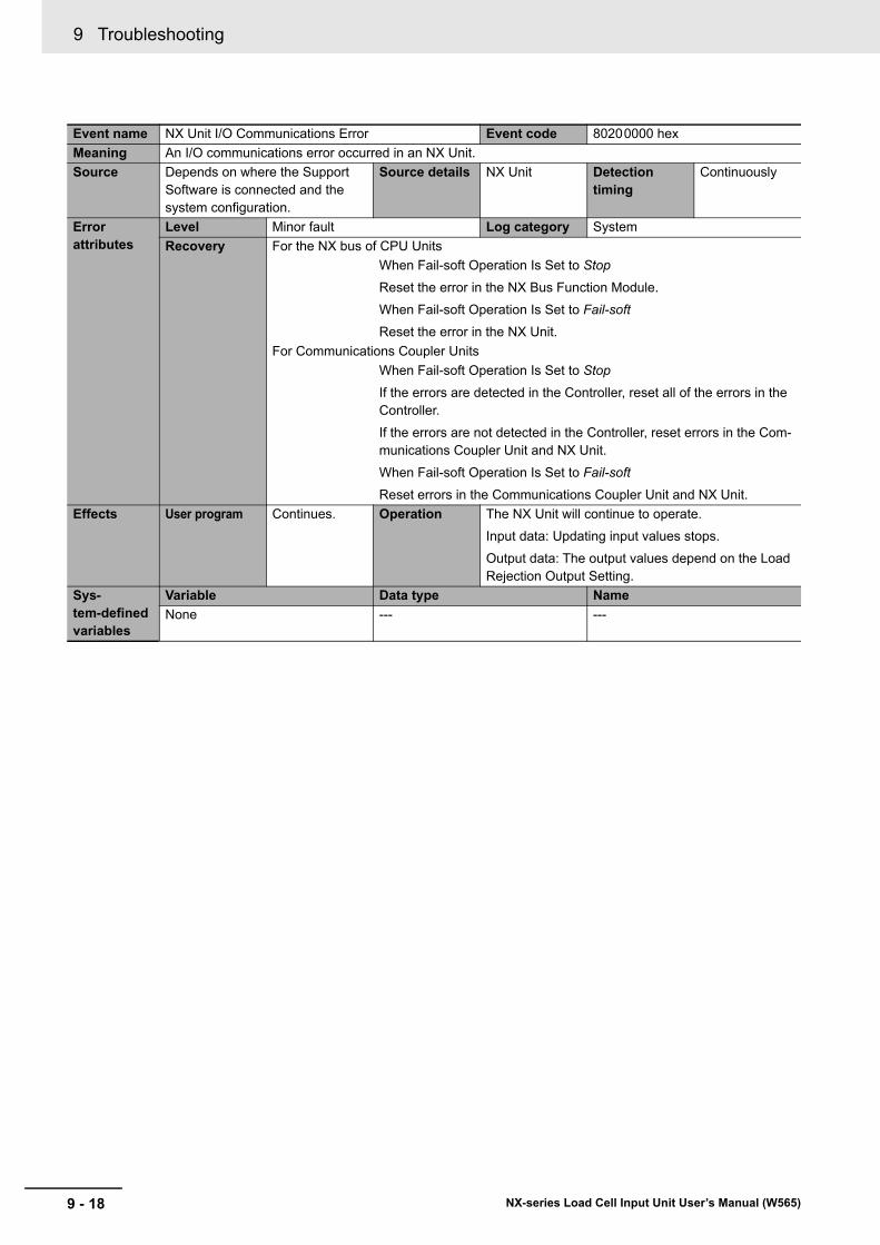
9 Troubleshooting
9 - 18 NX-series Load Cell Input Unit User’s Manual (W565)
Event name NX Unit I/O Communications Error Event code 80200000 hex
Meaning An I/O communications error occurred in an NX Unit.
Source Depends on where the Support Software is connected and the system configuration.
Source details NX Unit Detection timing
Continuously
Error attributes
Level Minor fault Log category System
Recovery For the NX bus of CPU Units
When Fail-soft Operation Is Set to Stop
Reset the error in the NX Bus Function Module.
When Fail-soft Operation Is Set to Fail-soft
Reset the error in the NX Unit.
For Communications Coupler Units
When Fail-soft Operation Is Set to Stop
If the errors are detected in the Controller, reset all of the errors in the Controller.
If the errors are not detected in the Controller, reset errors in the Com-munications Coupler Unit and NX Unit.
When Fail-soft Operation Is Set to Fail-soft
Reset errors in the Communications Coupler Unit and NX Unit.
Effects User program Continues. Operation The NX Unit will continue to operate.
Input data: Updating input values stops.
Output data: The output values depend on the Load Rejection Output Setting.
Sys-tem-defined variables
Variable Data type Name
None --- ---
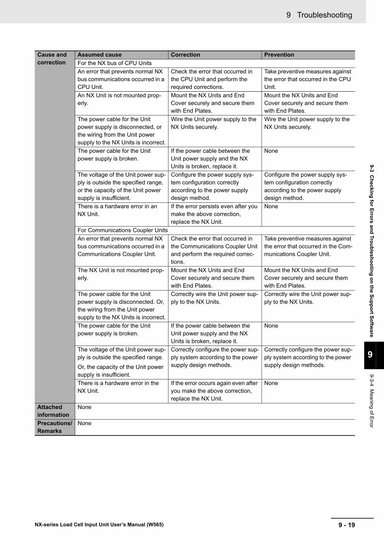
9 - 19
9 Troubleshooting
NX-series Load Cell Input Unit User’s Manual (W565)
9-3 Ch
ecking
for E
rrors an
d Tro
ub
lesho
otin
g o
n th
e Su
pp
ort S
oftw
are
9
9-3-4 Meaning of E
rror
Cause and correction
Assumed cause Correction Prevention
For the NX bus of CPU Units
An error that prevents normal NX bus communications occurred in a CPU Unit.
Check the error that occurred in the CPU Unit and perform the required corrections.
Take preventive measures against the error that occurred in the CPU Unit.
An NX Unit is not mounted prop-erly.
Mount the NX Units and End Cover securely and secure them with End Plates.
Mount the NX Units and End Cover securely and secure them with End Plates.
The power cable for the Unit power supply is disconnected, or the wiring from the Unit power supply to the NX Units is incorrect.
Wire the Unit power supply to the NX Units securely.
Wire the Unit power supply to the NX Units securely.
The power cable for the Unit power supply is broken.
If the power cable between the Unit power supply and the NX Units is broken, replace it.
None
The voltage of the Unit power sup-ply is outside the specified range, or the capacity of the Unit power supply is insufficient.
Configure the power supply sys-tem configuration correctly according to the power supply design method.
Configure the power supply sys-tem configuration correctly according to the power supply design method.
There is a hardware error in an NX Unit.
If the error persists even after you make the above correction, replace the NX Unit.
None
For Communications Coupler Units
An error that prevents normal NX bus communications occurred in a Communications Coupler Unit.
Check the error that occurred in the Communications Coupler Unit and perform the required correc-tions.
Take preventive measures against the error that occurred in the Com-munications Coupler Unit.
The NX Unit is not mounted prop-erly.
Mount the NX Units and End Cover securely and secure them with End Plates.
Mount the NX Units and End Cover securely and secure them with End Plates.
The power cable for the Unit power supply is disconnected. Or, the wiring from the Unit power supply to the NX Units is incorrect.
Correctly wire the Unit power sup-ply to the NX Units.
Correctly wire the Unit power sup-ply to the NX Units.
The power cable for the Unit power supply is broken.
If the power cable between the Unit power supply and the NX Units is broken, replace it.
None
The voltage of the Unit power sup-ply is outside the specified range.
Or, the capacity of the Unit power supply is insufficient.
Correctly configure the power sup-ply system according to the power supply design methods.
Correctly configure the power sup-ply system according to the power supply design methods.
There is a hardware error in the NX Unit.
If the error occurs again even after you make the above correction, replace the NX Unit.
None
Attached information
None
Precautions/Remarks
None
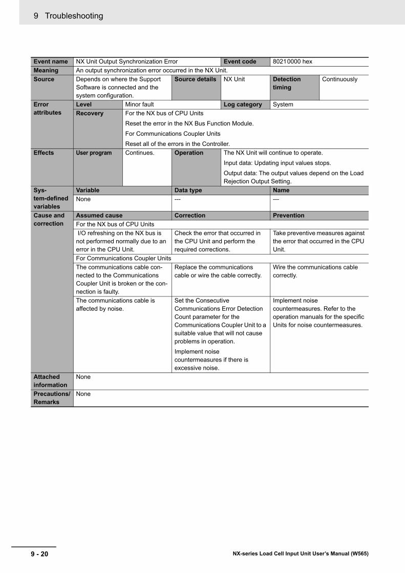
9 Troubleshooting
9 - 20 NX-series Load Cell Input Unit User’s Manual (W565)
Event name NX Unit Output Synchronization Error Event code 80210000 hex
Meaning An output synchronization error occurred in the NX Unit.
Source Depends on where the Support Software is connected and the system configuration.
Source details NX Unit Detection timing
Continuously
Error attributes
Level Minor fault Log category System
Recovery For the NX bus of CPU Units
Reset the error in the NX Bus Function Module.
For Communications Coupler Units
Reset all of the errors in the Controller.
Effects User program Continues. Operation The NX Unit will continue to operate.
Input data: Updating input values stops.
Output data: The output values depend on the Load Rejection Output Setting.
Sys-tem-defined variables
Variable Data type Name
None --- ---
Cause and correction
Assumed cause Correction Prevention
For the NX bus of CPU Units
I/O refreshing on the NX bus is not performed normally due to an error in the CPU Unit.
Check the error that occurred in the CPU Unit and perform the required corrections.
Take preventive measures against the error that occurred in the CPU Unit.
For Communications Coupler Units
The communications cable con-nected to the Communications Coupler Unit is broken or the con-nection is faulty.
Replace the communications cable or wire the cable correctly.
Wire the communications cable correctly.
The communications cable is affected by noise.
Set the Consecutive Communications Error Detection Count parameter for the Communications Coupler Unit to a suitable value that will not cause problems in operation.
Implement noise countermeasures if there is excessive noise.
Implement noise countermeasures. Refer to the operation manuals for the specific Units for noise countermeasures.
Attached information
None
Precautions/Remarks
None
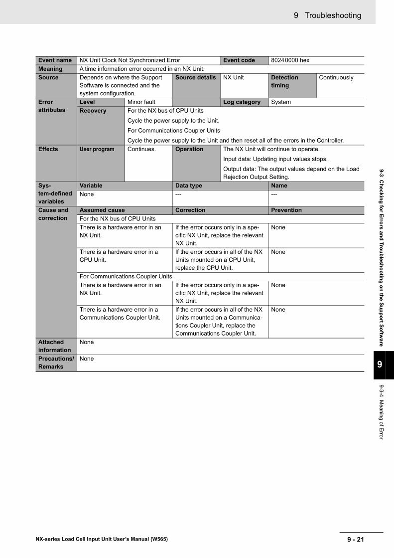
9 - 21
9 Troubleshooting
NX-series Load Cell Input Unit User’s Manual (W565)
9-3 Ch
ecking
for E
rrors an
d Tro
ub
lesho
otin
g o
n th
e Su
pp
ort S
oftw
are
9
9-3-4 Meaning of E
rror
Event name NX Unit Clock Not Synchronized Error Event code 80240000 hex
Meaning A time information error occurred in an NX Unit.
Source Depends on where the Support Software is connected and the system configuration.
Source details NX Unit Detection timing
Continuously
Error attributes
Level Minor fault Log category System
Recovery For the NX bus of CPU Units
Cycle the power supply to the Unit.
For Communications Coupler Units
Cycle the power supply to the Unit and then reset all of the errors in the Controller.
Effects User program Continues. Operation The NX Unit will continue to operate.
Input data: Updating input values stops.
Output data: The output values depend on the Load Rejection Output Setting.
Sys-tem-defined variables
Variable Data type Name
None --- ---
Cause and correction
Assumed cause Correction Prevention
For the NX bus of CPU Units
There is a hardware error in an NX Unit.
If the error occurs only in a spe-cific NX Unit, replace the relevant NX Unit.
None
There is a hardware error in a CPU Unit.
If the error occurs in all of the NX Units mounted on a CPU Unit, replace the CPU Unit.
None
For Communications Coupler Units
There is a hardware error in an NX Unit.
If the error occurs only in a spe-cific NX Unit, replace the relevant NX Unit.
None
There is a hardware error in a Communications Coupler Unit.
If the error occurs in all of the NX Units mounted on a Communica-tions Coupler Unit, replace the Communications Coupler Unit.
None
Attached information
None
Precautions/Remarks
None
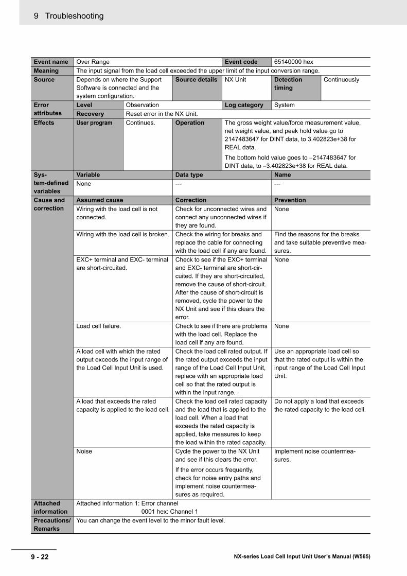
9 Troubleshooting
9 - 22 NX-series Load Cell Input Unit User’s Manual (W565)
Event name Over Range Event code 65140000 hex
Meaning The input signal from the load cell exceeded the upper limit of the input conversion range.
Source Depends on where the Support Software is connected and the system configuration.
Source details NX Unit Detection timing
Continuously
Error attributes
Level Observation Log category System
Recovery Reset error in the NX Unit.
Effects User program Continues. Operation The gross weight value/force measurement value, net weight value, and peak hold value go to 2147483647 for DINT data, to 3.402823e+38 for REAL data.
The bottom hold value goes to 2147483647 for DINT data, to 3.402823e+38 for REAL data.
Sys-tem-defined variables
Variable Data type Name
None --- ---
Cause and correction
Assumed cause Correction Prevention
Wiring with the load cell is not connected.
Check for unconnected wires and connect any unconnected wires if they are found.
None
Wiring with the load cell is broken. Check the wiring for breaks and replace the cable for connecting with the load cell if any are found.
Find the reasons for the breaks and take suitable preventive mea-sures.
EXC+ terminal and EXC- terminal are short-circuited.
Check to see if the EXC+ terminal and EXC- terminal are short-cir-cuited. If they are short-circuited, remove the cause of short-circuit. After the cause of short-circuit is removed, cycle the power to the NX Unit and see if this clears the error.
None
Load cell failure. Check to see if there are problems with the load cell. Replace the load cell if any are found.
None
A load cell with which the rated output exceeds the input range of the Load Cell Input Unit is used.
Check the load cell rated output. If the rated output exceeds the input range of the Load Cell Input Unit, replace with an appropriate load cell so that the rated output is within the input range.
Use an appropriate load cell so that the rated output is within the input range of the Load Cell Input Unit.
A load that exceeds the rated capacity is applied to the load cell.
Check the load cell rated capacity and the load that is applied to the load cell. When a load that exceeds the rated capacity is applied, take measures to keep the load within the rated capacity.
Do not apply a load that exceeds the rated capacity to the load cell.
Noise Cycle the power to the NX Unit and see if this clears the error.
If the error occurs frequently, check for noise entry paths and implement noise countermea-sures as required.
Implement noise countermea-sures.
Attached information
Attached information 1: Error channel0001 hex: Channel 1
Precautions/Remarks
You can change the event level to the minor fault level.
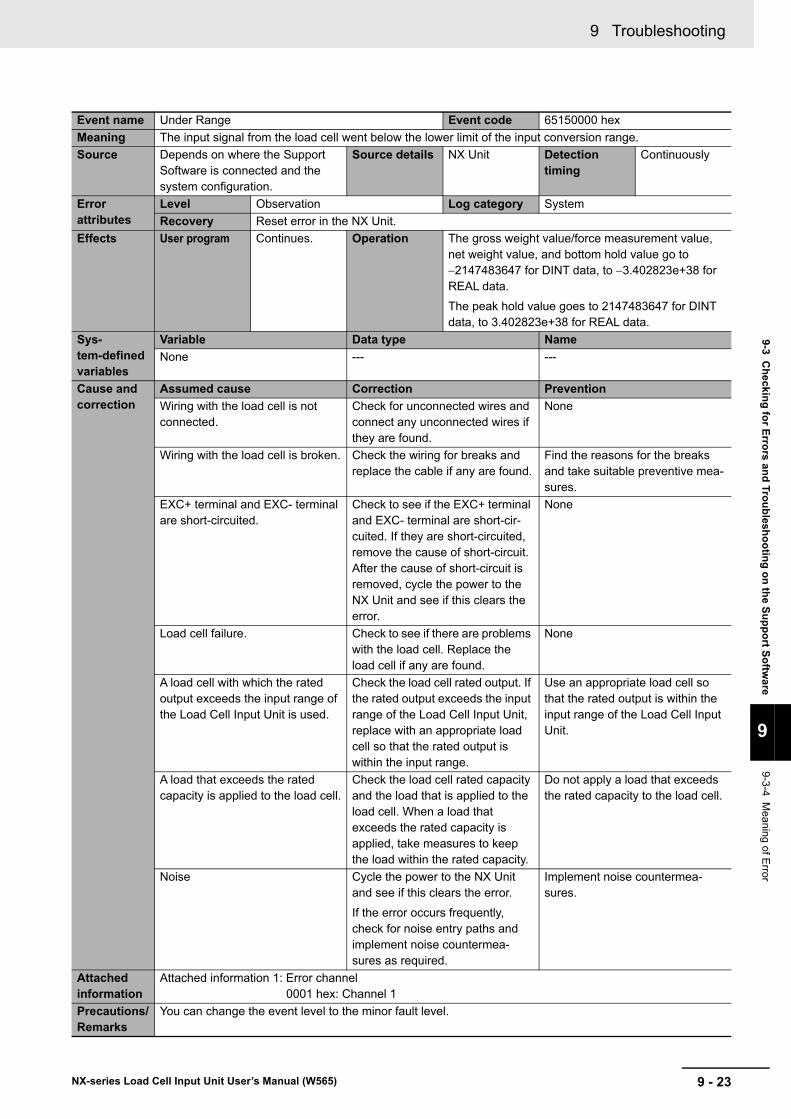
9 - 23
9 Troubleshooting
NX-series Load Cell Input Unit User’s Manual (W565)
9-3 Ch
ecking
for E
rrors an
d Tro
ub
lesho
otin
g o
n th
e Su
pp
ort S
oftw
are
9
9-3-4 Meaning of E
rror
Event name Under Range Event code 65150000 hex
Meaning The input signal from the load cell went below the lower limit of the input conversion range.
Source Depends on where the Support Software is connected and the system configuration.
Source details NX Unit Detection timing
Continuously
Error attributes
Level Observation Log category System
Recovery Reset error in the NX Unit.
Effects User program Continues. Operation The gross weight value/force measurement value, net weight value, and bottom hold value go to 2147483647 for DINT data, to 3.402823e+38 for REAL data.
The peak hold value goes to 2147483647 for DINT data, to 3.402823e+38 for REAL data.
Sys-tem-defined variables
Variable Data type Name
None --- ---
Cause and correction
Assumed cause Correction Prevention
Wiring with the load cell is not connected.
Check for unconnected wires and connect any unconnected wires if they are found.
None
Wiring with the load cell is broken. Check the wiring for breaks and replace the cable if any are found.
Find the reasons for the breaks and take suitable preventive mea-sures.
EXC+ terminal and EXC- terminal are short-circuited.
Check to see if the EXC+ terminal and EXC- terminal are short-cir-cuited. If they are short-circuited, remove the cause of short-circuit. After the cause of short-circuit is removed, cycle the power to the NX Unit and see if this clears the error.
None
Load cell failure. Check to see if there are problems with the load cell. Replace the load cell if any are found.
None
A load cell with which the rated output exceeds the input range of the Load Cell Input Unit is used.
Check the load cell rated output. If the rated output exceeds the input range of the Load Cell Input Unit, replace with an appropriate load cell so that the rated output is within the input range.
Use an appropriate load cell so that the rated output is within the input range of the Load Cell Input Unit.
A load that exceeds the rated capacity is applied to the load cell.
Check the load cell rated capacity and the load that is applied to the load cell. When a load that exceeds the rated capacity is applied, take measures to keep the load within the rated capacity.
Do not apply a load that exceeds the rated capacity to the load cell.
Noise Cycle the power to the NX Unit and see if this clears the error.
If the error occurs frequently, check for noise entry paths and implement noise countermea-sures as required.
Implement noise countermea-sures.
Attached information
Attached information 1: Error channel0001 hex: Channel 1
Precautions/Remarks
You can change the event level to the minor fault level.
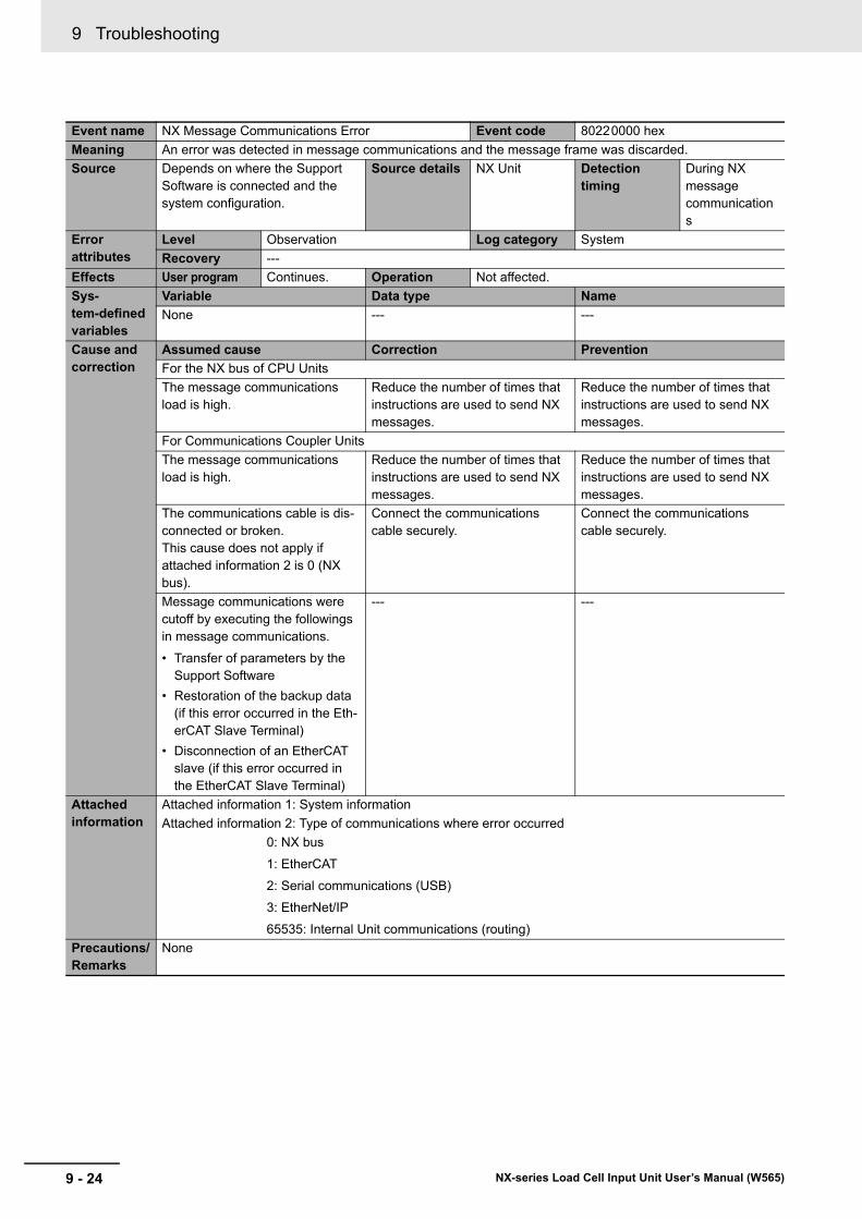
9 Troubleshooting
9 - 24 NX-series Load Cell Input Unit User’s Manual (W565)
Event name NX Message Communications Error Event code 80220000 hex
Meaning An error was detected in message communications and the message frame was discarded.
Source Depends on where the Support Software is connected and the system configuration.
Source details NX Unit Detection timing
During NX message communications
Error attributes
Level Observation Log category System
Recovery ---
Effects User program Continues. Operation Not affected.
Sys-tem-defined variables
Variable Data type Name
None --- ---
Cause and correction
Assumed cause Correction Prevention
For the NX bus of CPU Units
The message communications load is high.
Reduce the number of times that instructions are used to send NX messages.
Reduce the number of times that instructions are used to send NX messages.
For Communications Coupler Units
The message communications load is high.
Reduce the number of times that instructions are used to send NX messages.
Reduce the number of times that instructions are used to send NX messages.
The communications cable is dis-connected or broken.This cause does not apply if attached information 2 is 0 (NX bus).
Connect the communications cable securely.
Connect the communications cable securely.
Message communications were cutoff by executing the followings in message communications.
• Transfer of parameters by the Support Software
• Restoration of the backup data (if this error occurred in the Eth-erCAT Slave Terminal)
• Disconnection of an EtherCAT slave (if this error occurred in the EtherCAT Slave Terminal)
--- ---
Attached information
Attached information 1: System information
Attached information 2: Type of communications where error occurred
0: NX bus
1: EtherCAT
2: Serial communications (USB)
3: EtherNet/IP
65535: Internal Unit communications (routing)
Precautions/Remarks
None
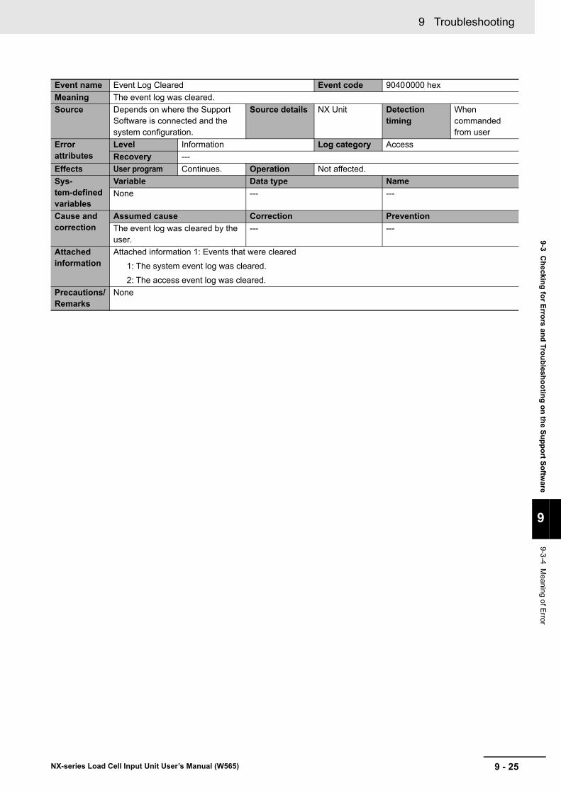
9 - 25
9 Troubleshooting
NX-series Load Cell Input Unit User’s Manual (W565)
9-3 Ch
ecking
for E
rrors an
d Tro
ub
lesho
otin
g o
n th
e Su
pp
ort S
oftw
are
9
9-3-4 Meaning of E
rror
Event name Event Log Cleared Event code 90400000 hex
Meaning The event log was cleared.
Source Depends on where the Support Software is connected and the system configuration.
Source details NX Unit Detection timing
When commanded from user
Error attributes
Level Information Log category Access
Recovery ---
Effects User program Continues. Operation Not affected.
Sys-tem-defined variables
Variable Data type Name
None --- ---
Cause and correction
Assumed cause Correction Prevention
The event log was cleared by the user.
--- ---
Attached information
Attached information 1: Events that were cleared
1: The system event log was cleared.
2: The access event log was cleared.
Precautions/Remarks
None
9 Troubleshooting
9 - 26 NX-series Load Cell Input Unit User’s Manual (W565)
9-4 Resetting Errors
Refer to the user’s manual for the connected CPU Unit or Communications Coupler Unit for details on how to reset errors.
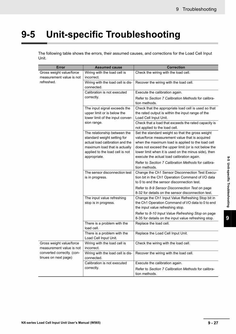
9 - 27
9 Troubleshooting
NX-series Load Cell Input Unit User’s Manual (W565)
9-5 Un
it-specific T
rou
blesh
oo
ting
9
9-5 Unit-specific Troubleshooting
The following table shows the errors, their assumed causes, and corrections for the Load Cell Input Unit.
Error Assumed cause Correction
Gross weight value/force measurement value is not refreshed.
Wiring with the load cell is incorrect.
Check the wiring with the load cell.
Wiring with the load cell is dis-connected.
Recover the wiring with the load cell.
Calibration is not executed correctly.
Execute the calibration again.
Refer to Section 7 Calibration Methods for calibra-tion methods.
The input signal exceeds the upper limit or is below the lower limit of the input conver-sion range.
Check that the appropriate load cell is used so that the rated output is within the input range of the Load Cell Input Unit.
Check that a load that exceeds the rated capacity is not applied to the load cell.
The relationship between the standard weight setting for actual load calibration and the maximum load that is actually applied to the load cell is not appropriate.
Set the standard weight so that the gross weight value/force measurement value that is acquired when the maximum load is applied to the load cell does not exceed the upper limit (or is not below the lower limit when it is used on the minus side), then execute the actual load calibration again.
Refer to Section 7 Calibration Methods for calibra-tion methods.
The sensor disconnection test is in progress.
Change the Ch1 Sensor Disconnection Test Execu-tion bit in the Ch1 Operation Command of I/O data to 0 to end the sensor disconnection test.
Refer to 8-9 Sensor Disconnection Test on page 8-32 for details on the sensor disconnection test.
The input value refreshing stop is in progress.
Change the Ch1 Input Value Refreshing Stop bit in the Ch1 Operation Command of I/O data to 0 to end the input value refreshing stop.
Refer to 8-10 Input Value Refreshing Stop on page 8-35 for details on the input value refreshing stop.
There is a problem with the load cell.
Replace the load cell.
There is a problem with the Load Cell Input Unit.
Replace the Load Cell Input Unit.
Gross weight value/force measurement value is not converted correctly. (con-tinues on next page)
Wiring with the load cell is incorrect.
Check the wiring with the load cell.
Wiring with the load cell is dis-connected.
Recover the wiring with the load cell.
Calibration is not executed correctly.
Execute the calibration again.
Refer to Section 7 Calibration Methods for calibra-tion methods.
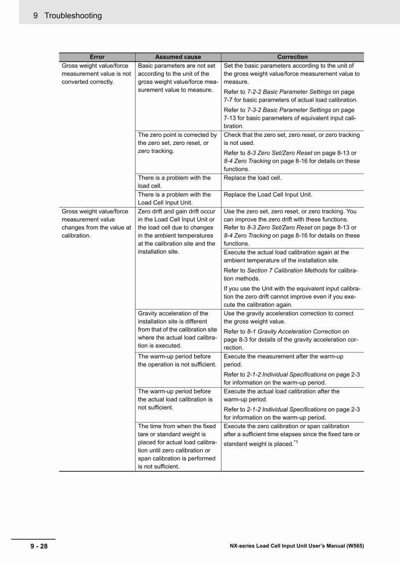
9 Troubleshooting
9 - 28 NX-series Load Cell Input Unit User’s Manual (W565)
Gross weight value/force measurement value is not converted correctly.
Basic parameters are not set according to the unit of the gross weight value/force mea-surement value to measure.
Set the basic parameters according to the unit of the gross weight value/force measurement value to measure.
Refer to 7-2-2 Basic Parameter Settings on page 7-7 for basic parameters of actual load calibration.
Refer to 7-3-2 Basic Parameter Settings on page 7-13 for basic parameters of equivalent input cali-bration.
The zero point is corrected by the zero set, zero reset, or zero tracking.
Check that the zero set, zero reset, or zero tracking is not used.
Refer to 8-3 Zero Set/Zero Reset on page 8-13 or 8-4 Zero Tracking on page 8-16 for details on these functions.
There is a problem with the load cell.
Replace the load cell.
There is a problem with the Load Cell Input Unit.
Replace the Load Cell Input Unit.
Gross weight value/force measurement value changes from the value at calibration.
Zero drift and gain drift occur in the Load Cell Input Unit or the load cell due to changes in the ambient temperatures at the calibration site and the installation site.
Use the zero set, zero reset, or zero tracking. You can improve the zero drift with these functions. Refer to 8-3 Zero Set/Zero Reset on page 8-13 or 8-4 Zero Tracking on page 8-16 for details on these functions.
Execute the actual load calibration again at the ambient temperature of the installation site.
Refer to Section 7 Calibration Methods for calibra-tion methods.
If you use the Unit with the equivalent input calibra-tion the zero drift cannot improve even if you exe-cute the calibration again.
Gravity acceleration of the installation site is different from that of the calibration site where the actual load calibra-tion is executed.
Use the gravity acceleration correction to correct the gross weight value.
Refer to 8-1 Gravity Acceleration Correction on page 8-3 for details of the gravity acceleration cor-rection.
The warm-up period before the operation is not sufficient.
Execute the measurement after the warm-up period.
Refer to 2-1-2 Individual Specifications on page 2-3 for information on the warm-up period.
The warm-up period before the actual load calibration is not sufficient.
Execute the actual load calibration after the warm-up period.
Refer to 2-1-2 Individual Specifications on page 2-3 for information on the warm-up period.
The time from when the fixed tare or standard weight is placed for actual load calibra-tion until zero calibration or span calibration is performed is not sufficient.
Execute the zero calibration or span calibration after a sufficient time elapses since the fixed tare or
standard weight is placed.*1
Error Assumed cause Correction
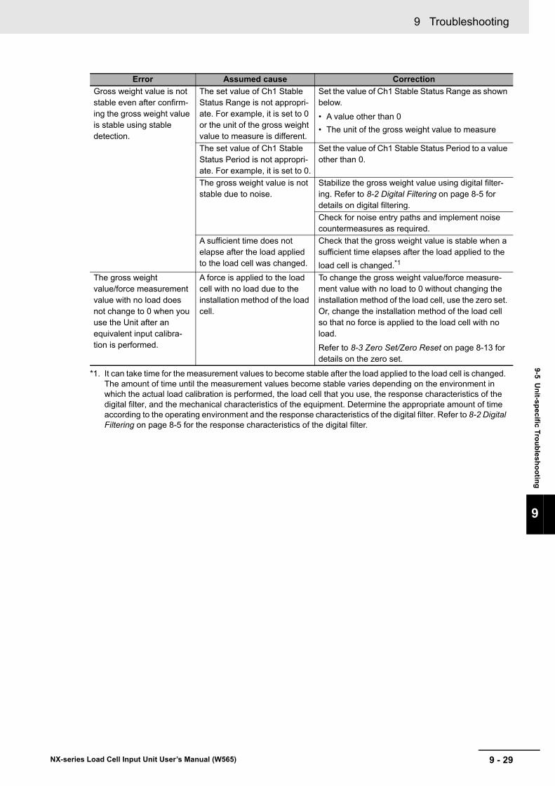
9 - 29
9 Troubleshooting
NX-series Load Cell Input Unit User’s Manual (W565)
9-5 Un
it-specific T
rou
blesh
oo
ting
9
Gross weight value is not stable even after confirm-ing the gross weight value is stable using stable detection.
The set value of Ch1 Stable Status Range is not appropri-ate. For example, it is set to 0 or the unit of the gross weight value to measure is different.
Set the value of Ch1 Stable Status Range as shown below.
• A value other than 0
• The unit of the gross weight value to measure
The set value of Ch1 Stable Status Period is not appropri-ate. For example, it is set to 0.
Set the value of Ch1 Stable Status Period to a value other than 0.
The gross weight value is not stable due to noise.
Stabilize the gross weight value using digital filter-ing. Refer to 8-2 Digital Filtering on page 8-5 for details on digital filtering.
Check for noise entry paths and implement noise countermeasures as required.
A sufficient time does not elapse after the load applied to the load cell was changed.
Check that the gross weight value is stable when a sufficient time elapses after the load applied to the
load cell is changed.*1
The gross weight value/force measurement value with no load does not change to 0 when you use the Unit after an equivalent input calibra-tion is performed.
A force is applied to the load cell with no load due to the installation method of the load cell.
To change the gross weight value/force measure-ment value with no load to 0 without changing the installation method of the load cell, use the zero set. Or, change the installation method of the load cell so that no force is applied to the load cell with no load.
Refer to 8-3 Zero Set/Zero Reset on page 8-13 for details on the zero set.
*1. It can take time for the measurement values to become stable after the load applied to the load cell is changed. The amount of time until the measurement values become stable varies depending on the environment in which the actual load calibration is performed, the load cell that you use, the response characteristics of the digital filter, and the mechanical characteristics of the equipment. Determine the appropriate amount of time according to the operating environment and the response characteristics of the digital filter. Refer to 8-2 Digital Filtering on page 8-5 for the response characteristics of the digital filter.
Error Assumed cause Correction
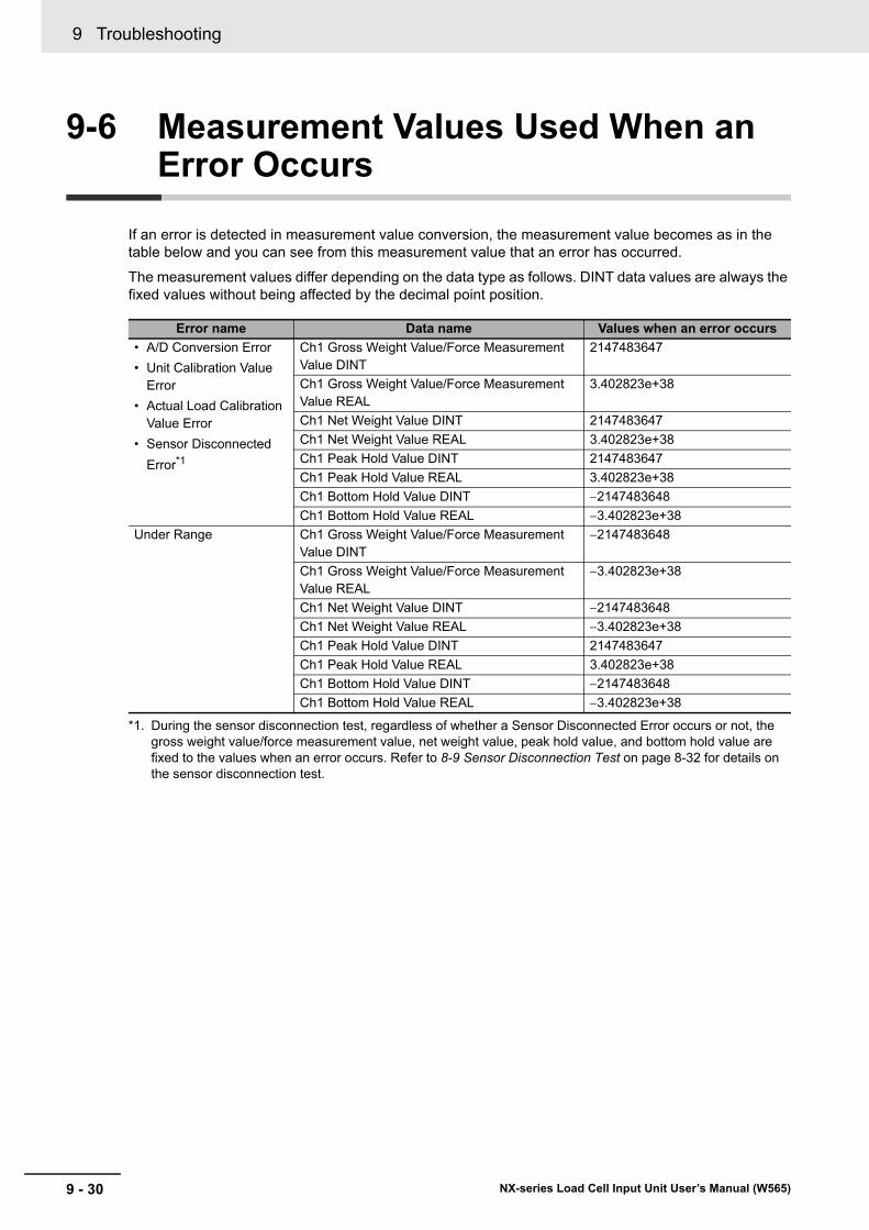
9 Troubleshooting
9 - 30 NX-series Load Cell Input Unit User’s Manual (W565)
9-6 Measurement Values Used When an Error Occurs
If an error is detected in measurement value conversion, the measurement value becomes as in the table below and you can see from this measurement value that an error has occurred.
The measurement values differ depending on the data type as follows. DINT data values are always the fixed values without being affected by the decimal point position.
Error name Data name Values when an error occurs
• A/D Conversion Error
• Unit Calibration Value Error
• Actual Load Calibration Value Error
• Sensor Disconnected
Error*1
*1. During the sensor disconnection test, regardless of whether a Sensor Disconnected Error occurs or not, the gross weight value/force measurement value, net weight value, peak hold value, and bottom hold value are fixed to the values when an error occurs. Refer to 8-9 Sensor Disconnection Test on page 8-32 for details on the sensor disconnection test.
Ch1 Gross Weight Value/Force Measurement Value DINT
2147483647
Ch1 Gross Weight Value/Force Measurement Value REAL
3.402823e+38
Ch1 Net Weight Value DINT 2147483647
Ch1 Net Weight Value REAL 3.402823e+38
Ch1 Peak Hold Value DINT 2147483647
Ch1 Peak Hold Value REAL 3.402823e+38
Ch1 Bottom Hold Value DINT 2147483648
Ch1 Bottom Hold Value REAL 3.402823e+38
Under Range Ch1 Gross Weight Value/Force Measurement Value DINT
2147483648
Ch1 Gross Weight Value/Force Measurement Value REAL
3.402823e+38
Ch1 Net Weight Value DINT 2147483648
Ch1 Net Weight Value REAL 3.402823e+38
Ch1 Peak Hold Value DINT 2147483647
Ch1 Peak Hold Value REAL 3.402823e+38
Ch1 Bottom Hold Value DINT 2147483648
Ch1 Bottom Hold Value REAL 3.402823e+38
9 - 31
9 Troubleshooting
NX-series Load Cell Input Unit User’s Manual (W565)
9-7 Trou
blesh
oo
ting
Flo
wch
art
9
9-7 Troubleshooting Flowchart
Refer to the user’s manual for the connected CPU Unit or Communications Coupler Unit for details on the standard troubleshooting process when an error occurs.

9 Troubleshooting
9 - 32 NX-series Load Cell Input Unit User’s Manual (W565)
10 - 1
10
NX-series Load Cell Input Unit User’s Manual (W565)
This section describes the procedures for cleaning, inspecting, and replacing the Load Cell Input Unit.
10-1 Cleaning and Inspection . . . . . . . . . . . . . . . . . . . . . . . . . . . . . . . . . . . . . . . 10-210-1-1 Cleaning . . . . . . . . . . . . . . . . . . . . . . . . . . . . . . . . . . . . . . . . . . . . . . . . . . . . . 10-2
10-1-2 Periodic Inspection . . . . . . . . . . . . . . . . . . . . . . . . . . . . . . . . . . . . . . . . . . . . . 10-2
10-2 Maintenance Procedures . . . . . . . . . . . . . . . . . . . . . . . . . . . . . . . . . . . . . . . 10-5
Inspection and Maintenance
10 Inspection and Maintenance
10 - 2 NX-series Load Cell Input Unit User’s Manual (W565)
10-1 Cleaning and Inspection
This section describes daily device maintenance such as cleaning and inspection.
Make sure to perform daily or periodic inspections in order to maintain the Load Cell Input Unit's
functions in the best operating condition.
Perform the following cleaning procedures periodically to ensure the Load Cell Input Unit is maintained
in the best operating condition.
• Wipe the equipment over with a soft, dry cloth when performing daily cleaning.
• If dirt remains even after wiping with a soft, dry cloth, wipe with a cloth that has been wet with a suffi-ciently diluted detergent (2%) and wrung dry.
• Units will become stained if items such as rubber, vinyl products, or adhesive tape are left on the NX Unit for a long period. Remove such items during regular cleaning.
Precautions for Correct Use
• Never use benzene, thinners, other volatile solvents, or chemical cloths.
• Do not touch the NX bus connectors.
NX Units do not have parts with a specific life. However, its elements can deteriorate under improper
environmental conditions. Periodic inspections are thus required to ensure that the required conditions
are being maintained.
Inspection is recommended at least once every six months to a year, but more frequent inspections
may be necessary depending on the severe environments.
Take immediate steps to correct the situation if any of the conditions in the following table are not met.
10-1-1 Cleaning
10-1-2 Periodic Inspection
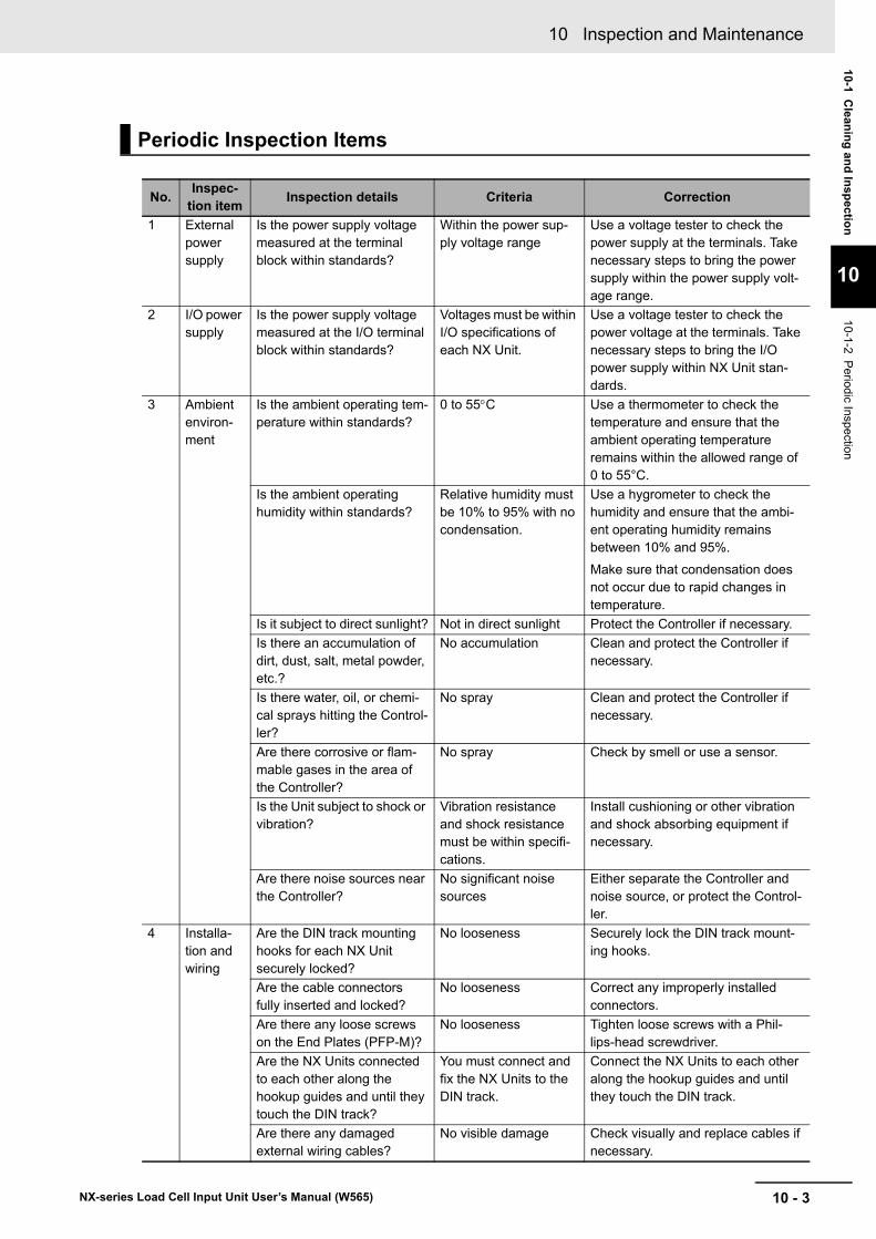
10 - 3
10 Inspection and Maintenance
NX-series Load Cell Input Unit User’s Manual (W565)
10-1 Clean
ing
and
Insp
ection
10
10-1-2
Periodic Inspection
Periodic Inspection Items
No.Inspec-
tion itemInspection details Criteria Correction
1 External power supply
Is the power supply voltage measured at the terminal block within standards?
Within the power sup-ply voltage range
Use a voltage tester to check the power supply at the terminals. Take necessary steps to bring the power supply within the power supply volt-age range.
2 I/O power supply
Is the power supply voltage measured at the I/O terminal block within standards?
Voltages must be within I/O specifications of each NX Unit.
Use a voltage tester to check the power voltage at the terminals. Take necessary steps to bring the I/O power supply within NX Unit stan-dards.
3 Ambient environ-ment
Is the ambient operating tem-perature within standards?
0 to 55C Use a thermometer to check the temperature and ensure that the ambient operating temperature remains within the allowed range of 0 to 55°C.
Is the ambient operating humidity within standards?
Relative humidity must be 10% to 95% with no condensation.
Use a hygrometer to check the humidity and ensure that the ambi-ent operating humidity remains between 10% and 95%.
Make sure that condensation does not occur due to rapid changes in temperature.
Is it subject to direct sunlight? Not in direct sunlight Protect the Controller if necessary.
Is there an accumulation of dirt, dust, salt, metal powder, etc.?
No accumulation Clean and protect the Controller if necessary.
Is there water, oil, or chemi-cal sprays hitting the Control-ler?
No spray Clean and protect the Controller if necessary.
Are there corrosive or flam-mable gases in the area of the Controller?
No spray Check by smell or use a sensor.
Is the Unit subject to shock or vibration?
Vibration resistance and shock resistance must be within specifi-cations.
Install cushioning or other vibration and shock absorbing equipment if necessary.
Are there noise sources near the Controller?
No significant noise sources
Either separate the Controller and noise source, or protect the Control-ler.
4 Installa-tion and wiring
Are the DIN track mounting hooks for each NX Unit securely locked?
No looseness Securely lock the DIN track mount-ing hooks.
Are the cable connectors fully inserted and locked?
No looseness Correct any improperly installed connectors.
Are there any loose screws on the End Plates (PFP-M)?
No looseness Tighten loose screws with a Phil-lips-head screwdriver.
Are the NX Units connected to each other along the hookup guides and until they touch the DIN track?
You must connect and fix the NX Units to the DIN track.
Connect the NX Units to each other along the hookup guides and until they touch the DIN track.
Are there any damaged external wiring cables?
No visible damage Check visually and replace cables if necessary.
10 Inspection and Maintenance
10 - 4 NX-series Load Cell Input Unit User’s Manual (W565)
Required Tools
• Phillips screwdriver
• Flat-blade screwdriver
• Voltage tester or digital voltmeter
• Industrial alcohol and pure cotton cloth
Tools Required Occasionally
• Oscilloscope
• Thermometer and hygrometer
Tools Required for Inspections
10 - 5
10 Inspection and Maintenance
NX-series Load Cell Input Unit User’s Manual (W565)
10-2 Main
ten
ance P
roced
ures
10
10-2 Maintenance Procedures
When you replace a Load Cell Input Unit, follow the procedure in the user’s manual for the connected CPU Unit or Communications Coupler Unit.
When you use the Load Cell Input Unit with the actual load calibration, execute the actual load calibra-tion again.

10 Inspection and Maintenance
10 - 6 NX-series Load Cell Input Unit User’s Manual (W565)
A - 1
A
NX-series Load Cell Input Unit User’s Manual (W565)
This appendix provides dimensions of the Load Cell Input Unit, examples of digital filter design that utilizes data tracing, and other information.
A-1 Dimensions . . . . . . . . . . . . . . . . . . . . . . . . . . . . . . . . . . . . . . . . . . . . . . . . . . . A-2
A-2 Digital Filter Design That Utilizes Data Tracing . . . . . . . . . . . . . . . . . . . . . . A-3A-2-1 System Configuration . . . . . . . . . . . . . . . . . . . . . . . . . . . . . . . . . . . . . . . . . . . . A-3
A-2-2 Examples of Digital Filter Design . . . . . . . . . . . . . . . . . . . . . . . . . . . . . . . . . . . A-4
A-3 List of NX Objects . . . . . . . . . . . . . . . . . . . . . . . . . . . . . . . . . . . . . . . . . . . . . A-7A-3-1 Format of NX Object Descriptions . . . . . . . . . . . . . . . . . . . . . . . . . . . . . . . . . . A-7
A-3-2 Unit Information Objects . . . . . . . . . . . . . . . . . . . . . . . . . . . . . . . . . . . . . . . . . . A-7
A-3-3 Objects That Accept I/O Allocations . . . . . . . . . . . . . . . . . . . . . . . . . . . . . . . . . A-8
A-3-4 Other Objects . . . . . . . . . . . . . . . . . . . . . . . . . . . . . . . . . . . . . . . . . . . . . . . . . A-13
A-4 Version Information with CPU Units . . . . . . . . . . . . . . . . . . . . . . . . . . . . . . A-18A-4-1 Relationship between Unit Versions of Units . . . . . . . . . . . . . . . . . . . . . . . . . A-18
A-5 Version Information with Communications Coupler Units . . . . . . . . . . . A-19A-5-1 Connection to the EtherCAT Coupler Unit . . . . . . . . . . . . . . . . . . . . . . . . . . . A-19
A-5-2 Connection to the EtherNet/IP Coupler Unit . . . . . . . . . . . . . . . . . . . . . . . . . . A-20
A-6 Display Methods for the Calibration View . . . . . . . . . . . . . . . . . . . . . . . . . A-21A-6-1 Connection to the CPU Unit . . . . . . . . . . . . . . . . . . . . . . . . . . . . . . . . . . . . . . A-21
A-6-2 Connection to the Communications Coupler Unit . . . . . . . . . . . . . . . . . . . . . . A-22
Appendices
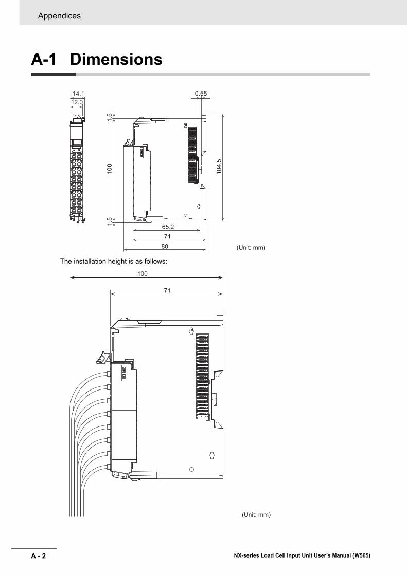
Appendices
A - 2 NX-series Load Cell Input Unit User’s Manual (W565)
A-1 Dimensions
The installation height is as follows:
(Unit: mm)8071
104.
5
100
14.1
65.2
12.01.
51.
5
0.55
100
71
(Unit: mm)
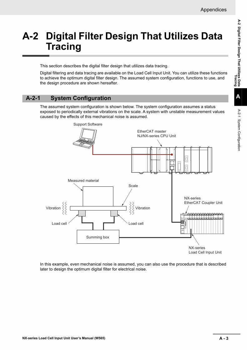
A - 3
Appendices
NX-series Load Cell Input Unit User’s Manual (W565)
A-2 D
igital F
ilter Desig
n T
hat U
tilizes Data
Tracing
A
A-2-1 S
ystem
Configuration
A-2 Digital Filter Design That Utilizes Data Tracing
This section describes the digital filter design that utilizes data tracing.
Digital filtering and data tracing are available on the Load Cell Input Unit. You can utilize these functions to achieve the optimum digital filter design. The assumed system configuration, functions to use, and the design procedure are shown hereafter.
The assumed system configuration is shown below. The system configuration assumes a status exposed to periodically external vibrations on the scale. A system with unstable measurement values caused by the effects of this mechanical noise is assumed.
In this example, even mechanical noise is assumed, you can also use the procedure that is described later to design the optimum digital filter for electrical noise.
A-2-1 System Configuration
EtherCAT master NJ/NX-series CPU Unit
Support Software
NX-series EtherCAT Coupler Unit
NX-series Load Cell Input Unit
Summing box
Load cell
Vibration Vibration
Load cell
ScaleMeasured material
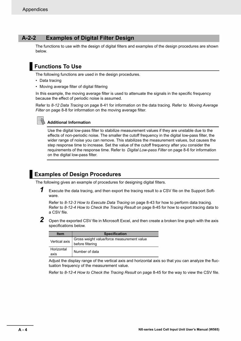
Appendices
A - 4 NX-series Load Cell Input Unit User’s Manual (W565)
The functions to use with the design of digital filters and examples of the design procedures are shown below.
The following functions are used in the design procedures.
• Data tracing
• Moving average filter of digital filtering
In this example, the moving average filter is used to attenuate the signals in the specific frequency because the effect of periodic noise is assumed.
Refer to 8-12 Data Tracing on page 8-41 for information on the data tracing. Refer to Moving Average Filter on page 8-8 for information on the moving average filter.
Additional Information
Use the digital low-pass filter to stabilize measurement values if they are unstable due to the effects of non-periodic noise. The smaller the cutoff frequency in the digital low-pass filter, the wider range of noise you can remove. This stabilizes the measurement values, but causes the step response time to increase. Set the value of the cutoff frequency after you consider the requirements of the response time. Refer to Digital Low-pass Filter on page 8-6 for information on the digital low-pass filter.
The following gives an example of procedures for designing digital filters.
1 Execute the data tracing, and then export the tracing result to a CSV file on the Support Soft-ware.
Refer to 8-12-3 How to Execute Data Tracing on page 8-43 for how to perform data tracing. Refer to 8-12-4 How to Check the Tracing Result on page 8-45 for how to export tracing data to a CSV file.
2 Open the exported CSV file in Microsoft Excel, and then create a broken line graph with the axis specifications below.
Adjust the display range of the vertical axis and horizontal axis so that you can analyze the fluc-tuation frequency of the measurement value.
Refer to 8-12-4 How to Check the Tracing Result on page 8-45 for the way to view the CSV file.
A-2-2 Examples of Digital Filter Design
Functions To Use
Examples of Design Procedures
Item Specification
Vertical axisGross weight value/force measurement value before filtering
Horizontal axis
Number of data
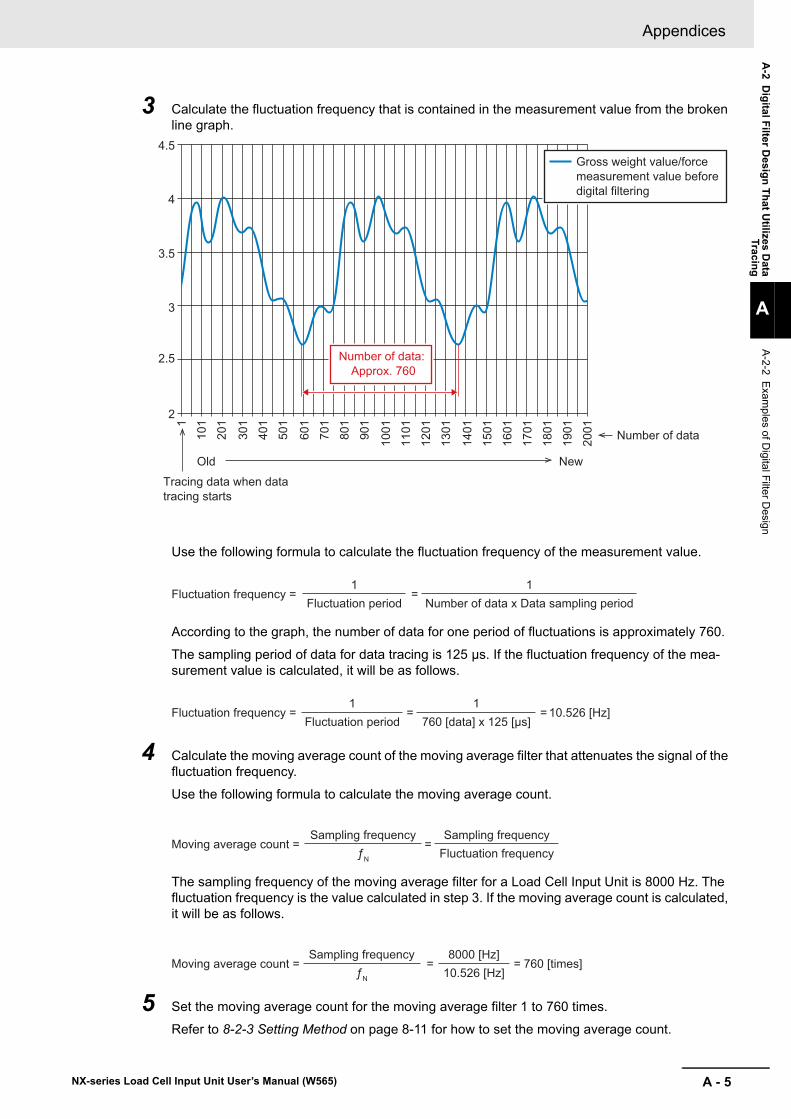
A - 5
Appendices
NX-series Load Cell Input Unit User’s Manual (W565)
A-2 D
igital F
ilter Desig
n T
hat U
tilizes Data
Tracing
A
A-2-2 E
xamples of D
igital Filte
r Design
3 Calculate the fluctuation frequency that is contained in the measurement value from the broken line graph.
Use the following formula to calculate the fluctuation frequency of the measurement value.
According to the graph, the number of data for one period of fluctuations is approximately 760.
The sampling period of data for data tracing is 125 μs. If the fluctuation frequency of the mea-surement value is calculated, it will be as follows.
4 Calculate the moving average count of the moving average filter that attenuates the signal of the fluctuation frequency.
Use the following formula to calculate the moving average count.
The sampling frequency of the moving average filter for a Load Cell Input Unit is 8000 Hz. The fluctuation frequency is the value calculated in step 3. If the moving average count is calculated, it will be as follows.
5 Set the moving average count for the moving average filter 1 to 760 times.
Refer to 8-2-3 Setting Method on page 8-11 for how to set the moving average count.
4.5
4
3.5
3
2.5
2
110
120
1
301
401
501
601
701
801
901
1001
1101
1201
1301
1401
1501
1601
1701
1801
1901
2001
Tracing data when data tracing starts
Old New
Number of data: Approx. 760
Gross weight value/force measurement value before digital filtering
Number of data
Fluctuation frequency = =1
Fluctuation period1
Number of data x Data sampling period
Fluctuation frequency = 10.526 [Hz]= =1
Fluctuation period1
760 [data] x 125 [μs]
Moving average count = =Sampling frequency
ƒN
Sampling frequencyFluctuation frequency
Moving average count = 760 [times]= =Sampling frequency
ƒN
8000 [Hz]10.526 [Hz]
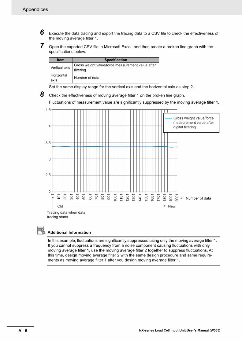
Appendices
A - 6 NX-series Load Cell Input Unit User’s Manual (W565)
6 Execute the data tracing and export the tracing data to a CSV file to check the effectiveness of the moving average filter 1.
7 Open the exported CSV file in Microsoft Excel, and then create a broken line graph with the specifications below.
Set the same display range for the vertical axis and the horizontal axis as step 2.
8 Check the effectiveness of moving average filter 1 on the broken line graph.
Fluctuations of measurement value are significantly suppressed by the moving average filter 1.
Additional Information
In this example, fluctuations are significantly suppressed using only the moving average filter 1. If you cannot suppress a frequency from a noise component causing fluctuations with only moving average filter 1, use the moving average filter 2 together to suppress fluctuations. At this time, design moving average filter 2 with the same design procedure and same require-ments as moving average filter 1 after you design moving average filter 1.
Item Specification
Vertical axisGross weight value/force measurement value after filtering
Horizontal axis
Number of data
4.5
4
3.5
3
2.5
2
110
120
1
301
401
501
601
701
801
901
1001
1101
1201
1301
1401
1501
1601
1701
1801
1901
2001
Tracing data when data tracing starts
Old New
Gross weight value/force measurement value after digital filtering
Number of data
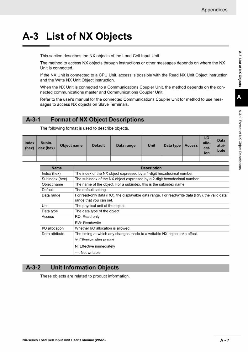
A - 7
Appendices
NX-series Load Cell Input Unit User’s Manual (W565)
A-3 L
ist of N
X O
bjects
A
A-3-1 F
ormat of N
X O
bject Descrip
tions
A-3 List of NX Objects
This section describes the NX objects of the Load Cell Input Unit.
The method to access NX objects through instructions or other messages depends on where the NX Unit is connected.
If the NX Unit is connected to a CPU Unit, access is possible with the Read NX Unit Object instruction and the Write NX Unit Object instruction.
When the NX Unit is connected to a Communications Coupler Unit, the method depends on the con-nected communications master and Communications Coupler Unit.
Refer to the user's manual for the connected Communications Coupler Unit for method to use mes-sages to access NX objects on Slave Terminals.
The following format is used to describe objects.
These objects are related to product information.
A-3-1 Format of NX Object Descriptions
Index (hex)
Subin-dex (hex)
Object name Default Data range Unit Data type Access
I/O allo-cat-ion
Data attri-bute
Name Description
Index (hex) The index of the NX object expressed by a 4-digit hexadecimal number.
Subindex (hex) The subindex of the NX object expressed by a 2-digit hexadecimal number.
Object name The name of the object. For a subindex, this is the subindex name.
Default The default setting.
Data range For read-only data (RO), the displayable data range. For read/write data (RW), the valid data range that you can set.
Unit The physical unit of the object.
Data type The data type of the object.
Access RO: Read only
RW: Read/write
I/O allocation Whether I/O allocation is allowed.
Data attribute The timing at which any changes made to a writable NX object take effect.
Y: Effective after restart
N: Effective immediately
---: Not writable
A-3-2 Unit Information Objects
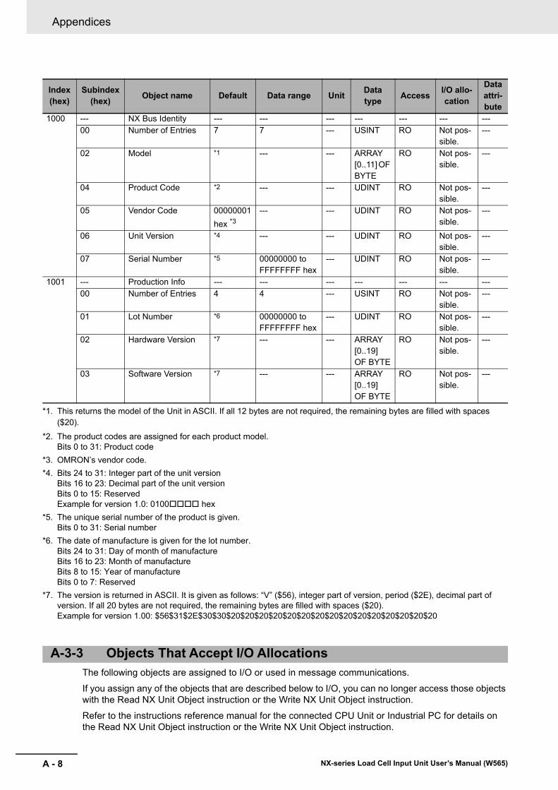
Appendices
A - 8 NX-series Load Cell Input Unit User’s Manual (W565)
The following objects are assigned to I/O or used in message communications.
If you assign any of the objects that are described below to I/O, you can no longer access those objects with the Read NX Unit Object instruction or the Write NX Unit Object instruction.
Refer to the instructions reference manual for the connected CPU Unit or Industrial PC for details on the Read NX Unit Object instruction or the Write NX Unit Object instruction.
Index(hex)
Subindex(hex)
Object name Default Data range UnitData type
AccessI/O allo-cation
Data attri-bute
1000 --- NX Bus Identity --- --- --- --- --- --- ---00 Number of Entries 7 7 --- USINT RO Not pos-
sible.---
02 Model *1
*1. This returns the model of the Unit in ASCII. If all 12 bytes are not required, the remaining bytes are filled with spaces ($20).
--- --- ARRAY [0..11] OF BYTE
RO Not pos-sible.
---
04 Product Code *2
*2. The product codes are assigned for each product model. Bits 0 to 31: Product code
--- --- UDINT RO Not pos-sible.
---
05 Vendor Code 00000001
hex *3
*3. OMRON’s vendor code.
--- --- UDINT RO Not pos-sible.
---
06 Unit Version *4
*4. Bits 24 to 31: Integer part of the unit versionBits 16 to 23: Decimal part of the unit versionBits 0 to 15: ReservedExample for version 1.0: 0100 hex
--- --- UDINT RO Not pos-sible.
---
07 Serial Number *5
*5. The unique serial number of the product is given. Bits 0 to 31: Serial number
00000000 to FFFFFFFF hex
--- UDINT RO Not pos-sible.
---
1001 --- Production Info --- --- --- --- --- --- ---00 Number of Entries 4 4 --- USINT RO Not pos-
sible.---
01 Lot Number *6
*6. The date of manufacture is given for the lot number. Bits 24 to 31: Day of month of manufactureBits 16 to 23: Month of manufactureBits 8 to 15: Year of manufactureBits 0 to 7: Reserved
00000000 to FFFFFFFF hex
--- UDINT RO Not pos-sible.
---
02 Hardware Version *7
*7. The version is returned in ASCII. It is given as follows: “V” ($56), integer part of version, period ($2E), decimal part of version. If all 20 bytes are not required, the remaining bytes are filled with spaces ($20).Example for version 1.00: $56$31$2E$30$30$20$20$20$20$20$20$20$20$20$20$20$20$20$20$20
--- --- ARRAY [0..19] OF BYTE
RO Not pos-sible.
---
03 Software Version *7 --- --- ARRAY [0..19] OF BYTE
RO Not pos-sible.
---
A-3-3 Objects That Accept I/O Allocations
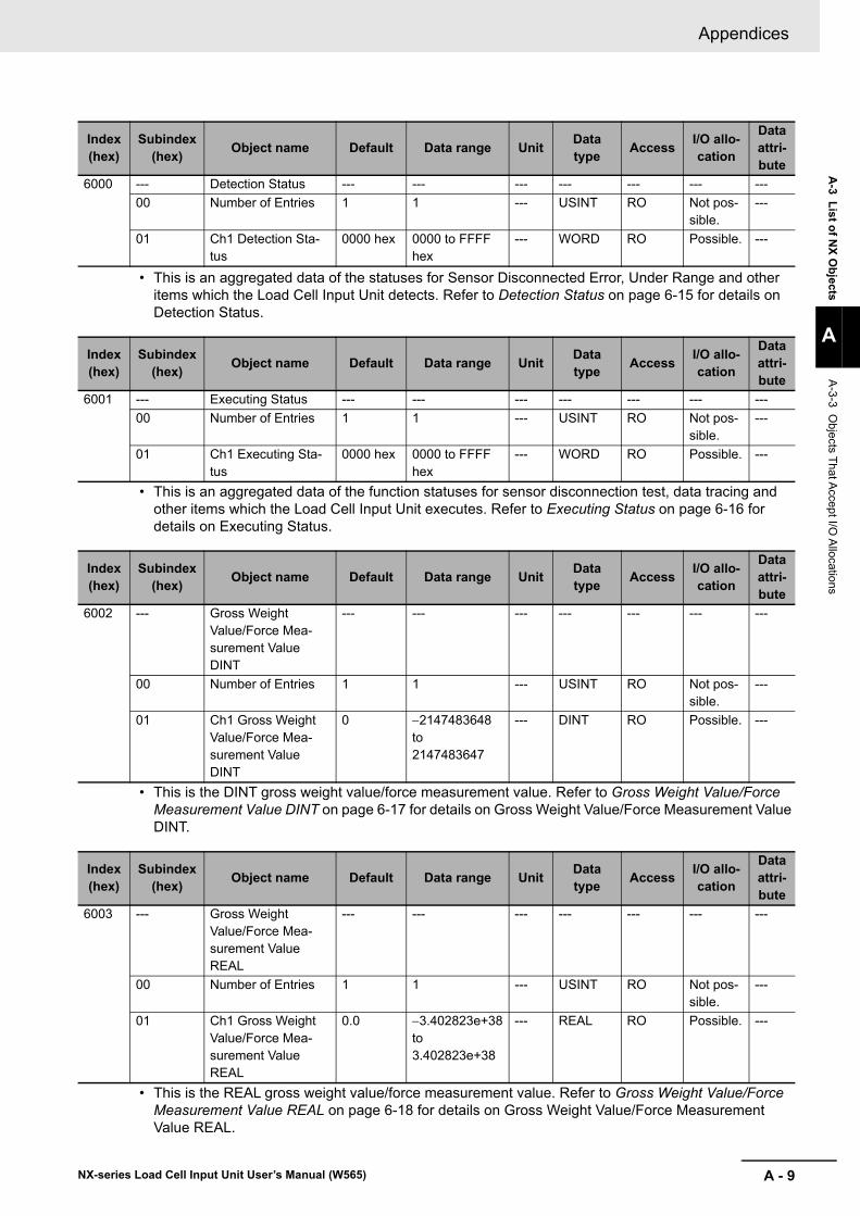
A - 9
Appendices
NX-series Load Cell Input Unit User’s Manual (W565)
A-3 L
ist of N
X O
bjects
A
A-3-3 O
bjects That A
ccept I/O A
llocations
• This is an aggregated data of the statuses for Sensor Disconnected Error, Under Range and other items which the Load Cell Input Unit detects. Refer to Detection Status on page 6-15 for details on Detection Status.
• This is an aggregated data of the function statuses for sensor disconnection test, data tracing and other items which the Load Cell Input Unit executes. Refer to Executing Status on page 6-16 for details on Executing Status.
• This is the DINT gross weight value/force measurement value. Refer to Gross Weight Value/Force Measurement Value DINT on page 6-17 for details on Gross Weight Value/Force Measurement Value DINT.
• This is the REAL gross weight value/force measurement value. Refer to Gross Weight Value/Force Measurement Value REAL on page 6-18 for details on Gross Weight Value/Force Measurement Value REAL.
Index (hex)
Subindex (hex)
Object name Default Data range UnitData type
AccessI/O allo-cation
Data attri-bute
6000 --- Detection Status --- --- --- --- --- --- ---
00 Number of Entries 1 1 --- USINT RO Not pos-sible.
---
01 Ch1 Detection Sta-tus
0000 hex 0000 to FFFF hex
--- WORD RO Possible. ---
Index (hex)
Subindex (hex)
Object name Default Data range UnitData type
AccessI/O allo-cation
Data attri-bute
6001 --- Executing Status --- --- --- --- --- --- ---
00 Number of Entries 1 1 --- USINT RO Not pos-sible.
---
01 Ch1 Executing Sta-tus
0000 hex 0000 to FFFF hex
--- WORD RO Possible. ---
Index (hex)
Subindex (hex)
Object name Default Data range UnitData type
AccessI/O allo-cation
Data attri-bute
6002 --- Gross Weight Value/Force Mea-surement Value DINT
--- --- --- --- --- --- ---
00 Number of Entries 1 1 --- USINT RO Not pos-sible.
---
01 Ch1 Gross Weight Value/Force Mea-surement Value DINT
0 2147483648 to 2147483647
--- DINT RO Possible. ---
Index (hex)
Subindex (hex)
Object name Default Data range UnitData type
AccessI/O allo-cation
Data attri-bute
6003 --- Gross Weight Value/Force Mea-surement Value REAL
--- --- --- --- --- --- ---
00 Number of Entries 1 1 --- USINT RO Not pos-sible.
---
01 Ch1 Gross Weight Value/Force Mea-surement Value REAL
0.0 3.402823e+38 to 3.402823e+38
--- REAL RO Possible. ---
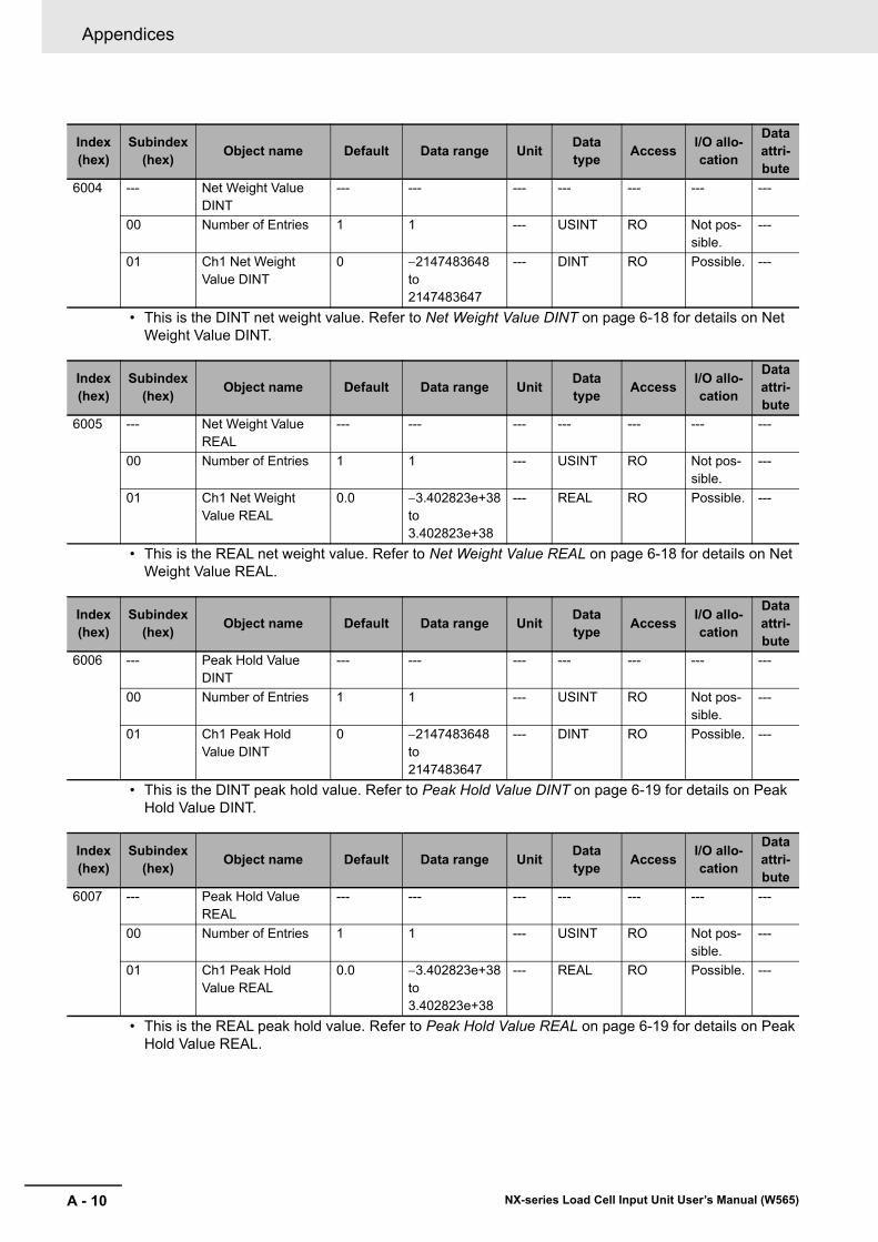
Appendices
A - 10 NX-series Load Cell Input Unit User’s Manual (W565)
• This is the DINT net weight value. Refer to Net Weight Value DINT on page 6-18 for details on Net Weight Value DINT.
• This is the REAL net weight value. Refer to Net Weight Value REAL on page 6-18 for details on Net Weight Value REAL.
• This is the DINT peak hold value. Refer to Peak Hold Value DINT on page 6-19 for details on Peak Hold Value DINT.
• This is the REAL peak hold value. Refer to Peak Hold Value REAL on page 6-19 for details on Peak Hold Value REAL.
Index (hex)
Subindex (hex)
Object name Default Data range UnitData type
AccessI/O allo-cation
Data attri-bute
6004 --- Net Weight Value DINT
--- --- --- --- --- --- ---
00 Number of Entries 1 1 --- USINT RO Not pos-sible.
---
01 Ch1 Net Weight Value DINT
0 2147483648 to 2147483647
--- DINT RO Possible. ---
Index (hex)
Subindex (hex)
Object name Default Data range UnitData type
AccessI/O allo-cation
Data attri-bute
6005 --- Net Weight Value REAL
--- --- --- --- --- --- ---
00 Number of Entries 1 1 --- USINT RO Not pos-sible.
---
01 Ch1 Net Weight Value REAL
0.0 3.402823e+38 to 3.402823e+38
--- REAL RO Possible. ---
Index (hex)
Subindex (hex)
Object name Default Data range UnitData type
AccessI/O allo-cation
Data attri-bute
6006 --- Peak Hold Value DINT
--- --- --- --- --- --- ---
00 Number of Entries 1 1 --- USINT RO Not pos-sible.
---
01 Ch1 Peak Hold Value DINT
0 2147483648 to 2147483647
--- DINT RO Possible. ---
Index (hex)
Subindex (hex)
Object name Default Data range UnitData type
AccessI/O allo-cation
Data attri-bute
6007 --- Peak Hold Value REAL
--- --- --- --- --- --- ---
00 Number of Entries 1 1 --- USINT RO Not pos-sible.
---
01 Ch1 Peak Hold Value REAL
0.0 3.402823e+38 to 3.402823e+38
--- REAL RO Possible. ---
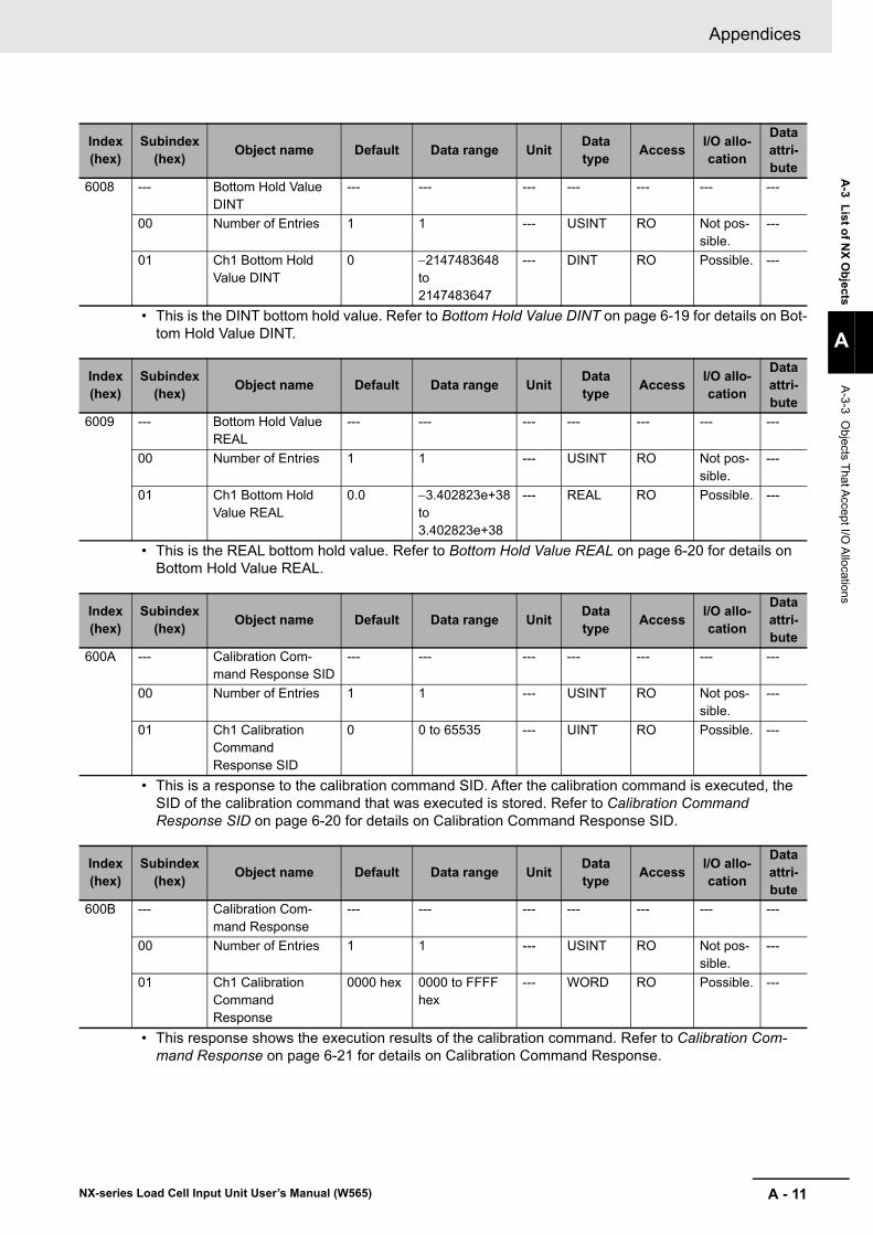
A - 11
Appendices
NX-series Load Cell Input Unit User’s Manual (W565)
A-3 L
ist of N
X O
bjects
A
A-3-3 O
bjects That A
ccept I/O A
llocations
• This is the DINT bottom hold value. Refer to Bottom Hold Value DINT on page 6-19 for details on Bot-tom Hold Value DINT.
• This is the REAL bottom hold value. Refer to Bottom Hold Value REAL on page 6-20 for details on Bottom Hold Value REAL.
• This is a response to the calibration command SID. After the calibration command is executed, the SID of the calibration command that was executed is stored. Refer to Calibration Command Response SID on page 6-20 for details on Calibration Command Response SID.
• This response shows the execution results of the calibration command. Refer to Calibration Com-mand Response on page 6-21 for details on Calibration Command Response.
Index (hex)
Subindex (hex)
Object name Default Data range UnitData type
AccessI/O allo-cation
Data attri-bute
6008 --- Bottom Hold Value DINT
--- --- --- --- --- --- ---
00 Number of Entries 1 1 --- USINT RO Not pos-sible.
---
01 Ch1 Bottom Hold Value DINT
0 2147483648 to 2147483647
--- DINT RO Possible. ---
Index (hex)
Subindex (hex)
Object name Default Data range UnitData type
AccessI/O allo-cation
Data attri-bute
6009 --- Bottom Hold Value REAL
--- --- --- --- --- --- ---
00 Number of Entries 1 1 --- USINT RO Not pos-sible.
---
01 Ch1 Bottom Hold Value REAL
0.0 3.402823e+38 to 3.402823e+38
--- REAL RO Possible. ---
Index (hex)
Subindex (hex)
Object name Default Data range UnitData type
AccessI/O allo-cation
Data attri-bute
600A --- Calibration Com-mand Response SID
--- --- --- --- --- --- ---
00 Number of Entries 1 1 --- USINT RO Not pos-sible.
---
01 Ch1 Calibration Command Response SID
0 0 to 65535 --- UINT RO Possible. ---
Index (hex)
Subindex (hex)
Object name Default Data range UnitData type
AccessI/O allo-cation
Data attri-bute
600B --- Calibration Com-mand Response
--- --- --- --- --- --- ---
00 Number of Entries 1 1 --- USINT RO Not pos-sible.
---
01 Ch1 Calibration Command Response
0000 hex 0000 to FFFF hex
--- WORD RO Possible. ---
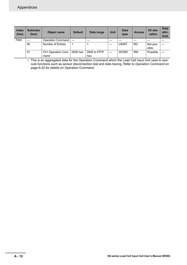
Appendices
A - 12 NX-series Load Cell Input Unit User’s Manual (W565)
• This is an aggregated data for the Operation Command which the Load Cell Input Unit uses to exe-cute functions such as sensor disconnection test and data tracing. Refer to Operation Command on page 6-22 for details on Operation Command.
Index (hex)
Subindex (hex)
Object name Default Data range UnitData type
AccessI/O allo-cation
Data attri-bute
7000 --- Operation Command --- --- --- --- --- --- ---
00 Number of Entries 1 1 --- USINT RO Not pos-sible.
---
01 Ch1 Operation Com-mand
0000 hex 0000 to FFFF hex
--- WORD RW Possible. ---
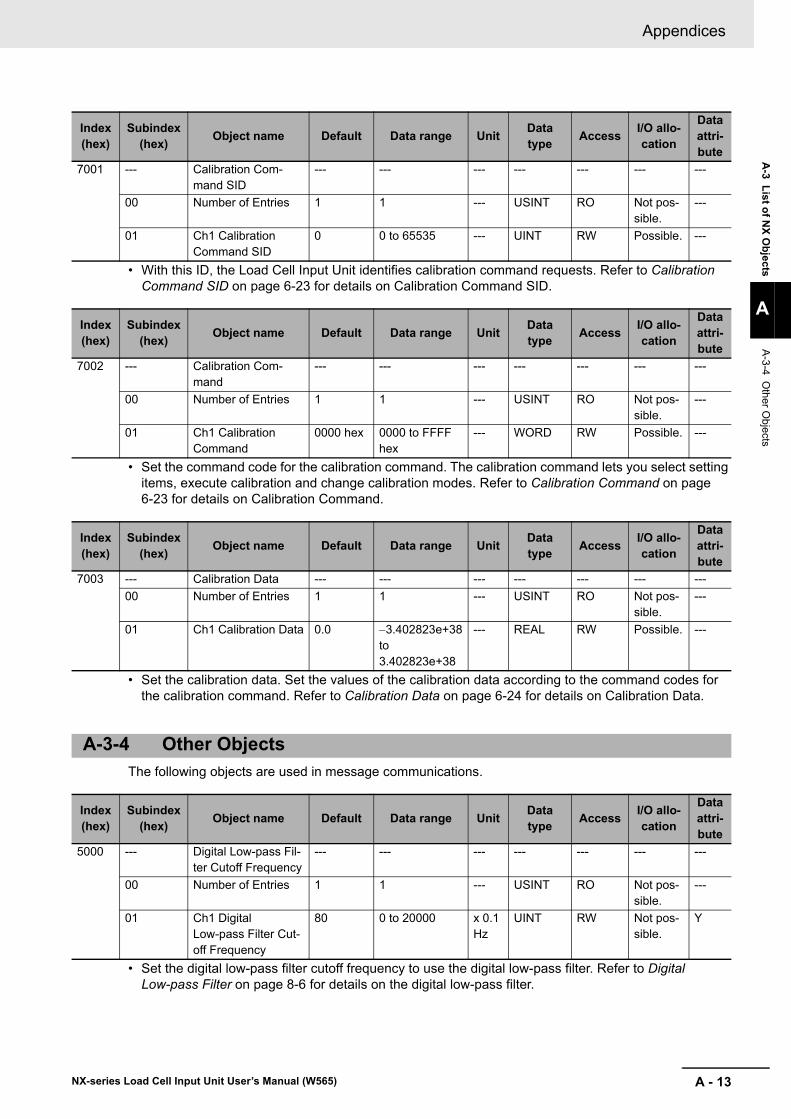
A - 13
Appendices
NX-series Load Cell Input Unit User’s Manual (W565)
A-3 L
ist of N
X O
bjects
A
A-3-4 O
ther Objects
• With this ID, the Load Cell Input Unit identifies calibration command requests. Refer to Calibration Command SID on page 6-23 for details on Calibration Command SID.
• Set the command code for the calibration command. The calibration command lets you select setting items, execute calibration and change calibration modes. Refer to Calibration Command on page 6-23 for details on Calibration Command.
• Set the calibration data. Set the values of the calibration data according to the command codes for the calibration command. Refer to Calibration Data on page 6-24 for details on Calibration Data.
The following objects are used in message communications.
• Set the digital low-pass filter cutoff frequency to use the digital low-pass filter. Refer to Digital Low-pass Filter on page 8-6 for details on the digital low-pass filter.
Index (hex)
Subindex (hex)
Object name Default Data range UnitData type
AccessI/O allo-cation
Data attri-bute
7001 --- Calibration Com-mand SID
--- --- --- --- --- --- ---
00 Number of Entries 1 1 --- USINT RO Not pos-sible.
---
01 Ch1 Calibration Command SID
0 0 to 65535 --- UINT RW Possible. ---
Index (hex)
Subindex (hex)
Object name Default Data range UnitData type
AccessI/O allo-cation
Data attri-bute
7002 --- Calibration Com-mand
--- --- --- --- --- --- ---
00 Number of Entries 1 1 --- USINT RO Not pos-sible.
---
01 Ch1 Calibration Command
0000 hex 0000 to FFFF hex
--- WORD RW Possible. ---
Index (hex)
Subindex (hex)
Object name Default Data range UnitData type
AccessI/O allo-cation
Data attri-bute
7003 --- Calibration Data --- --- --- --- --- --- ---
00 Number of Entries 1 1 --- USINT RO Not pos-sible.
---
01 Ch1 Calibration Data 0.0 3.402823e+38 to 3.402823e+38
--- REAL RW Possible. ---
A-3-4 Other Objects
Index (hex)
Subindex (hex)
Object name Default Data range UnitData type
AccessI/O allo-cation
Data attri-bute
5000 --- Digital Low-pass Fil-ter Cutoff Frequency
--- --- --- --- --- --- ---
00 Number of Entries 1 1 --- USINT RO Not pos-sible.
---
01 Ch1 Digital Low-pass Filter Cut-off Frequency
80 0 to 20000 x 0.1 Hz
UINT RW Not pos-sible.
Y
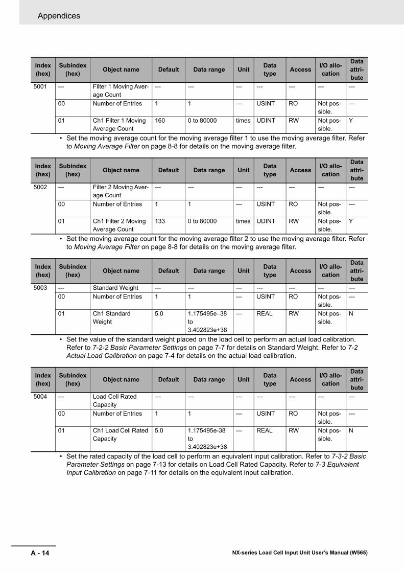
Appendices
A - 14 NX-series Load Cell Input Unit User’s Manual (W565)
• Set the moving average count for the moving average filter 1 to use the moving average filter. Refer to Moving Average Filter on page 8-8 for details on the moving average filter.
• Set the moving average count for the moving average filter 2 to use the moving average filter. Refer to Moving Average Filter on page 8-8 for details on the moving average filter.
• Set the value of the standard weight placed on the load cell to perform an actual load calibration. Refer to 7-2-2 Basic Parameter Settings on page 7-7 for details on Standard Weight. Refer to 7-2 Actual Load Calibration on page 7-4 for details on the actual load calibration.
• Set the rated capacity of the load cell to perform an equivalent input calibration. Refer to 7-3-2 Basic Parameter Settings on page 7-13 for details on Load Cell Rated Capacity. Refer to 7-3 Equivalent Input Calibration on page 7-11 for details on the equivalent input calibration.
Index (hex)
Subindex (hex)
Object name Default Data range UnitData type
AccessI/O allo-cation
Data attri-bute
5001 --- Filter 1 Moving Aver-age Count
--- --- --- --- --- --- ---
00 Number of Entries 1 1 --- USINT RO Not pos-sible.
---
01 Ch1 Filter 1 Moving Average Count
160 0 to 80000 times UDINT RW Not pos-sible.
Y
Index (hex)
Subindex (hex)
Object name Default Data range UnitData type
AccessI/O allo-cation
Data attri-bute
5002 --- Filter 2 Moving Aver-age Count
--- --- --- --- --- --- ---
00 Number of Entries 1 1 --- USINT RO Not pos-sible.
---
01 Ch1 Filter 2 Moving Average Count
133 0 to 80000 times UDINT RW Not pos-sible.
Y
Index (hex)
Subindex (hex)
Object name Default Data range UnitData type
AccessI/O allo-cation
Data attri-bute
5003 --- Standard Weight --- --- --- --- --- --- ---
00 Number of Entries 1 1 --- USINT RO Not pos-sible.
---
01 Ch1 Standard Weight
5.0 1.175495e38 to 3.402823e+38
--- REAL RW Not pos-sible.
N
Index (hex)
Subindex (hex)
Object name Default Data range UnitData type
AccessI/O allo-cation
Data attri-bute
5004 --- Load Cell Rated Capacity
--- --- --- --- --- --- ---
00 Number of Entries 1 1 --- USINT RO Not pos-sible.
---
01 Ch1 Load Cell Rated Capacity
5.0 1.175495e-38 to 3.402823e+38
--- REAL RW Not pos-sible.
N
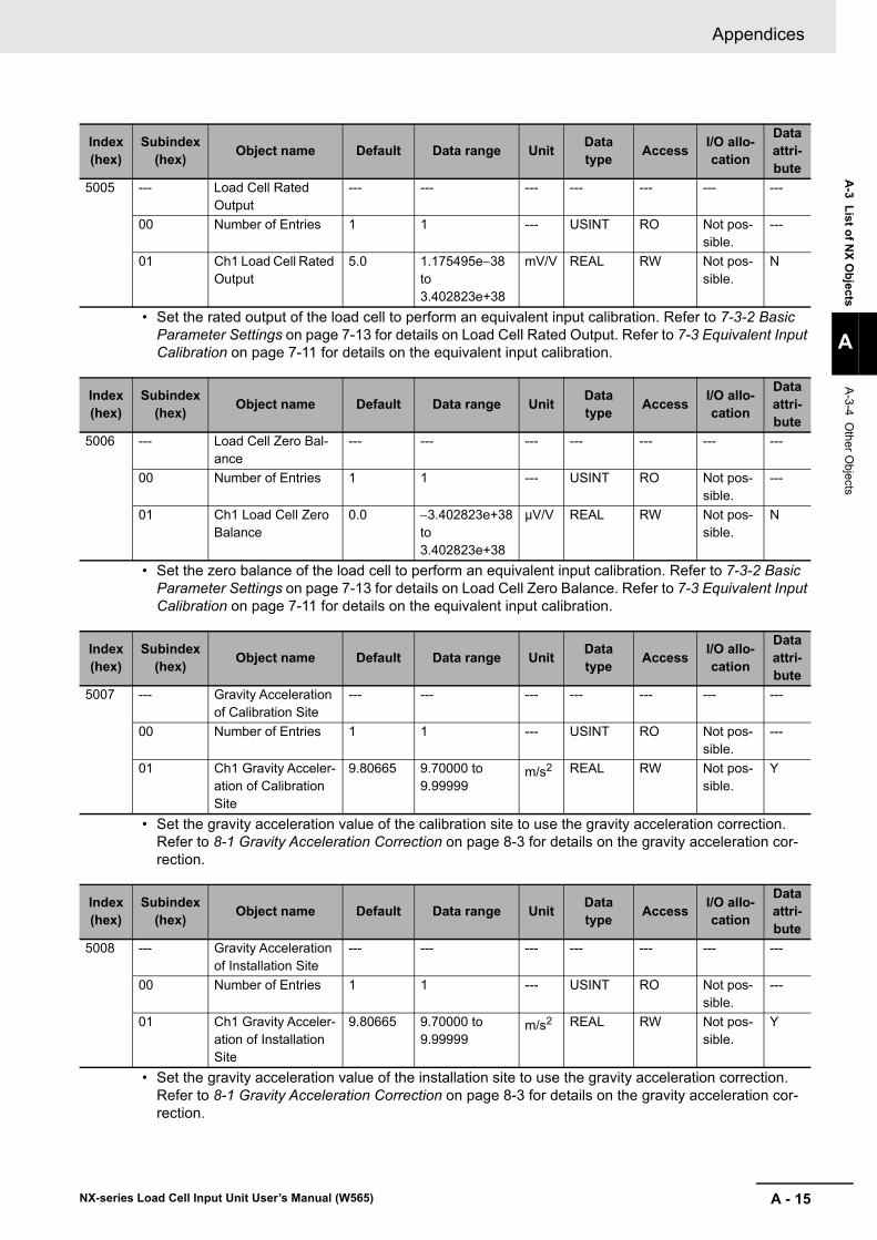
A - 15
Appendices
NX-series Load Cell Input Unit User’s Manual (W565)
A-3 L
ist of N
X O
bjects
A
A-3-4 O
ther Objects
• Set the rated output of the load cell to perform an equivalent input calibration. Refer to 7-3-2 Basic Parameter Settings on page 7-13 for details on Load Cell Rated Output. Refer to 7-3 Equivalent Input Calibration on page 7-11 for details on the equivalent input calibration.
• Set the zero balance of the load cell to perform an equivalent input calibration. Refer to 7-3-2 Basic Parameter Settings on page 7-13 for details on Load Cell Zero Balance. Refer to 7-3 Equivalent Input Calibration on page 7-11 for details on the equivalent input calibration.
• Set the gravity acceleration value of the calibration site to use the gravity acceleration correction. Refer to 8-1 Gravity Acceleration Correction on page 8-3 for details on the gravity acceleration cor-rection.
• Set the gravity acceleration value of the installation site to use the gravity acceleration correction. Refer to 8-1 Gravity Acceleration Correction on page 8-3 for details on the gravity acceleration cor-rection.
Index (hex)
Subindex (hex)
Object name Default Data range UnitData type
AccessI/O allo-cation
Data attri-bute
5005 --- Load Cell Rated Output
--- --- --- --- --- --- ---
00 Number of Entries 1 1 --- USINT RO Not pos-sible.
---
01 Ch1 Load Cell Rated Output
5.0 1.175495e38 to 3.402823e+38
mV/V REAL RW Not pos-sible.
N
Index (hex)
Subindex (hex)
Object name Default Data range UnitData type
AccessI/O allo-cation
Data attri-bute
5006 --- Load Cell Zero Bal-ance
--- --- --- --- --- --- ---
00 Number of Entries 1 1 --- USINT RO Not pos-sible.
---
01 Ch1 Load Cell Zero Balance
0.0 3.402823e+38 to 3.402823e+38
μV/V REAL RW Not pos-sible.
N
Index (hex)
Subindex (hex)
Object name Default Data range UnitData type
AccessI/O allo-cation
Data attri-bute
5007 --- Gravity Acceleration of Calibration Site
--- --- --- --- --- --- ---
00 Number of Entries 1 1 --- USINT RO Not pos-sible.
---
01 Ch1 Gravity Acceler-ation of Calibration Site
9.80665 9.70000 to 9.99999
m/s2 REAL RW Not pos-sible.
Y
Index (hex)
Subindex (hex)
Object name Default Data range UnitData type
AccessI/O allo-cation
Data attri-bute
5008 --- Gravity Acceleration of Installation Site
--- --- --- --- --- --- ---
00 Number of Entries 1 1 --- USINT RO Not pos-sible.
---
01 Ch1 Gravity Acceler-ation of Installation Site
9.80665 9.70000 to 9.99999
m/s2 REAL RW Not pos-sible.
Y
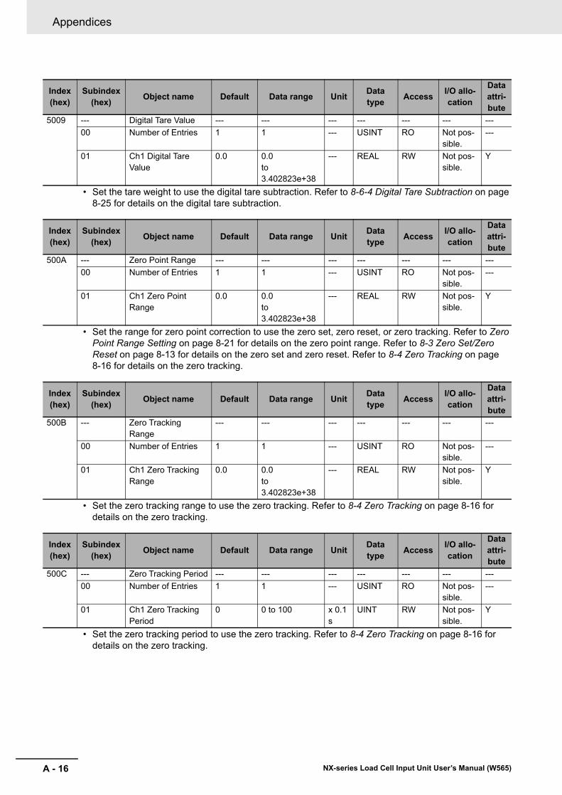
Appendices
A - 16 NX-series Load Cell Input Unit User’s Manual (W565)
• Set the tare weight to use the digital tare subtraction. Refer to 8-6-4 Digital Tare Subtraction on page 8-25 for details on the digital tare subtraction.
• Set the range for zero point correction to use the zero set, zero reset, or zero tracking. Refer to Zero Point Range Setting on page 8-21 for details on the zero point range. Refer to 8-3 Zero Set/Zero Reset on page 8-13 for details on the zero set and zero reset. Refer to 8-4 Zero Tracking on page 8-16 for details on the zero tracking.
• Set the zero tracking range to use the zero tracking. Refer to 8-4 Zero Tracking on page 8-16 for details on the zero tracking.
• Set the zero tracking period to use the zero tracking. Refer to 8-4 Zero Tracking on page 8-16 for details on the zero tracking.
Index (hex)
Subindex (hex)
Object name Default Data range UnitData type
AccessI/O allo-cation
Data attri-bute
5009 --- Digital Tare Value --- --- --- --- --- --- ---
00 Number of Entries 1 1 --- USINT RO Not pos-sible.
---
01 Ch1 Digital Tare Value
0.0 0.0 to 3.402823e+38
--- REAL RW Not pos-sible.
Y
Index (hex)
Subindex (hex)
Object name Default Data range UnitData type
AccessI/O allo-cation
Data attri-bute
500A --- Zero Point Range --- --- --- --- --- --- ---
00 Number of Entries 1 1 --- USINT RO Not pos-sible.
---
01 Ch1 Zero Point Range
0.0 0.0 to 3.402823e+38
--- REAL RW Not pos-sible.
Y
Index (hex)
Subindex (hex)
Object name Default Data range UnitData type
AccessI/O allo-cation
Data attri-bute
500B --- Zero Tracking Range
--- --- --- --- --- --- ---
00 Number of Entries 1 1 --- USINT RO Not pos-sible.
---
01 Ch1 Zero Tracking Range
0.0 0.0 to 3.402823e+38
--- REAL RW Not pos-sible.
Y
Index (hex)
Subindex (hex)
Object name Default Data range UnitData type
AccessI/O allo-cation
Data attri-bute
500C --- Zero Tracking Period --- --- --- --- --- --- ---
00 Number of Entries 1 1 --- USINT RO Not pos-sible.
---
01 Ch1 Zero Tracking Period
0 0 to 100 x 0.1 s
UINT RW Not pos-sible.
Y
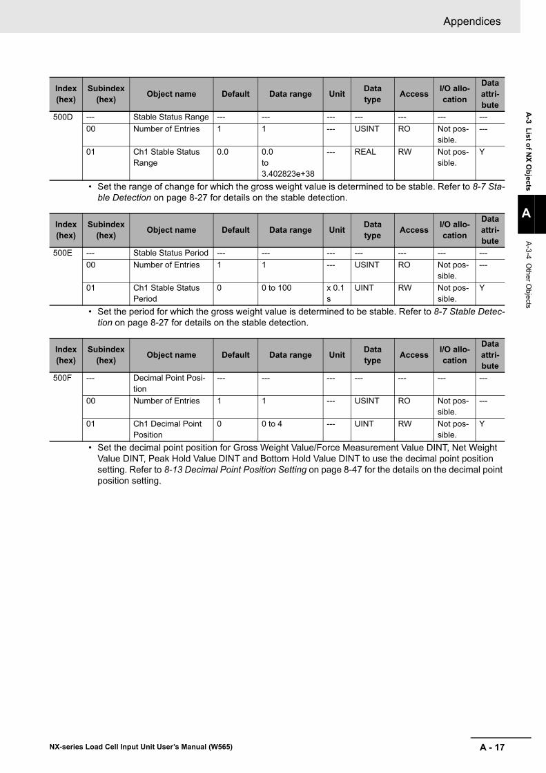
A - 17
Appendices
NX-series Load Cell Input Unit User’s Manual (W565)
A-3 L
ist of N
X O
bjects
A
A-3-4 O
ther Objects
• Set the range of change for which the gross weight value is determined to be stable. Refer to 8-7 Sta-ble Detection on page 8-27 for details on the stable detection.
• Set the period for which the gross weight value is determined to be stable. Refer to 8-7 Stable Detec-tion on page 8-27 for details on the stable detection.
• Set the decimal point position for Gross Weight Value/Force Measurement Value DINT, Net Weight Value DINT, Peak Hold Value DINT and Bottom Hold Value DINT to use the decimal point position setting. Refer to 8-13 Decimal Point Position Setting on page 8-47 for the details on the decimal point position setting.
Index (hex)
Subindex (hex)
Object name Default Data range UnitData type
AccessI/O allo-cation
Data attri-bute
500D --- Stable Status Range --- --- --- --- --- --- ---
00 Number of Entries 1 1 --- USINT RO Not pos-sible.
---
01 Ch1 Stable Status Range
0.0 0.0 to 3.402823e+38
--- REAL RW Not pos-sible.
Y
Index (hex)
Subindex (hex)
Object name Default Data range UnitData type
AccessI/O allo-cation
Data attri-bute
500E --- Stable Status Period --- --- --- --- --- --- ---
00 Number of Entries 1 1 --- USINT RO Not pos-sible.
---
01 Ch1 Stable Status Period
0 0 to 100 x 0.1 s
UINT RW Not pos-sible.
Y
Index (hex)
Subindex (hex)
Object name Default Data range UnitData type
AccessI/O allo-cation
Data attri-bute
500F --- Decimal Point Posi-tion
--- --- --- --- --- --- ---
00 Number of Entries 1 1 --- USINT RO Not pos-sible.
---
01 Ch1 Decimal Point Position
0 0 to 4 --- UINT RW Not pos-sible.
Y
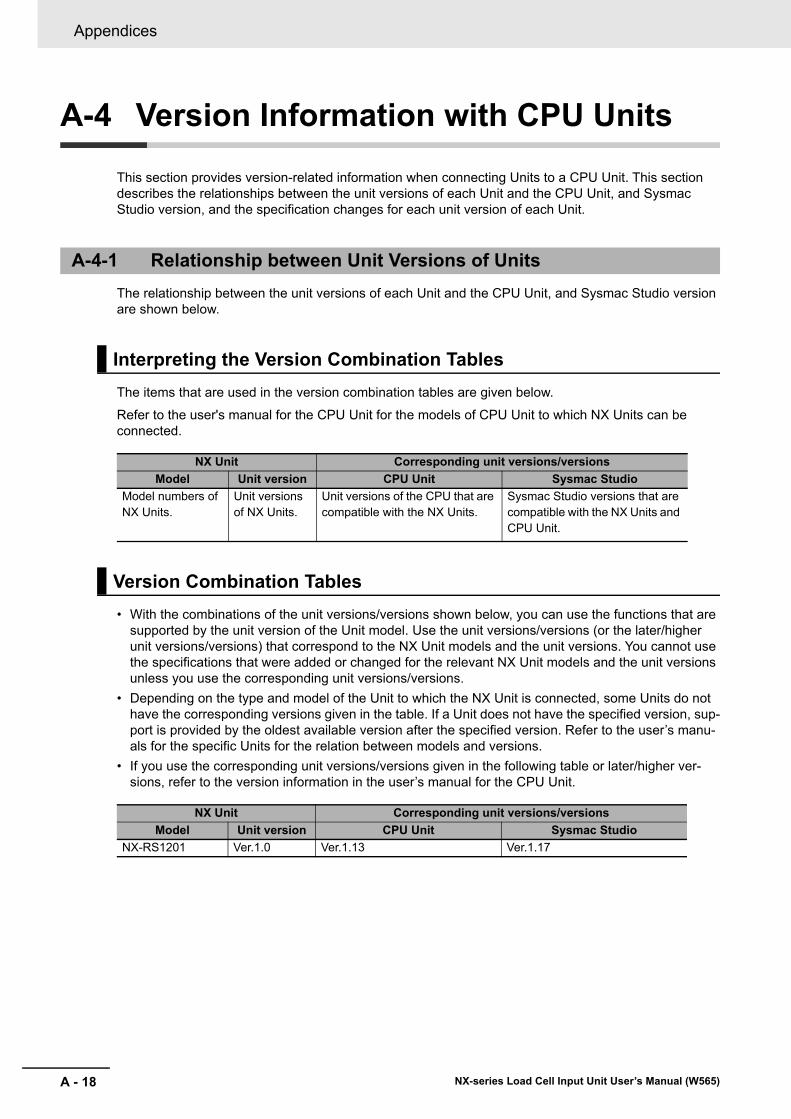
Appendices
A - 18 NX-series Load Cell Input Unit User’s Manual (W565)
A-4 Version Information with CPU Units
This section provides version-related information when connecting Units to a CPU Unit. This section describes the relationships between the unit versions of each Unit and the CPU Unit, and Sysmac Studio version, and the specification changes for each unit version of each Unit.
The relationship between the unit versions of each Unit and the CPU Unit, and Sysmac Studio version are shown below.
The items that are used in the version combination tables are given below.
Refer to the user's manual for the CPU Unit for the models of CPU Unit to which NX Units can be connected.
• With the combinations of the unit versions/versions shown below, you can use the functions that are supported by the unit version of the Unit model. Use the unit versions/versions (or the later/higher unit versions/versions) that correspond to the NX Unit models and the unit versions. You cannot use the specifications that were added or changed for the relevant NX Unit models and the unit versions unless you use the corresponding unit versions/versions.
• Depending on the type and model of the Unit to which the NX Unit is connected, some Units do not have the corresponding versions given in the table. If a Unit does not have the specified version, sup-port is provided by the oldest available version after the specified version. Refer to the user’s manu-als for the specific Units for the relation between models and versions.
• If you use the corresponding unit versions/versions given in the following table or later/higher ver-sions, refer to the version information in the user’s manual for the CPU Unit.
A-4-1 Relationship between Unit Versions of Units
Interpreting the Version Combination Tables
NX Unit Corresponding unit versions/versions
Model Unit version CPU Unit Sysmac Studio
Model numbers of NX Units.
Unit versions of NX Units.
Unit versions of the CPU that are compatible with the NX Units.
Sysmac Studio versions that are compatible with the NX Units and CPU Unit.
Version Combination Tables
NX Unit Corresponding unit versions/versions
Model Unit version CPU Unit Sysmac Studio
NX-RS1201 Ver.1.0 Ver.1.13 Ver.1.17
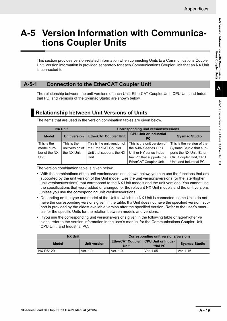
A - 19
Appendices
NX-series Load Cell Input Unit User’s Manual (W565)
A-5 V
ersio
n In
form
ation
with
Co
mm
un
ica-tio
ns C
ou
pler U
nits
A
A-5-1 C
onnection to
the EtherC
AT
Coupler U
nit
A-5 Version Information with Communica-tions Coupler Units
This section provides version-related information when connecting Units to a Communications Coupler Unit. Version information is provided separately for each Communications Coupler Unit that an NX Unit is connected to.
The relationship between the unit versions of each Unit, EtherCAT Coupler Unit, CPU Unit and Indus-trial PC, and versions of the Sysmac Studio are shown below.
The items that are used in the version combination tables are given below.
The version combination table is given below.
• With the combinations of the unit versions/versions shown below, you can use the functions that are supported by the unit version of the Unit model. Use the unit versions/versions (or the later/higher unit versions/versions) that correspond to the NX Unit models and the unit versions. You cannot use the specifications that were added or changed for the relevant NX Unit models and the unit versions unless you use the corresponding unit versions/versions.
• Depending on the type and model of the Unit to which the NX Unit is connected, some Units do not have the corresponding versions given in the table. If a Unit does not have the specified version, sup-port is provided by the oldest available version after the specified version. Refer to the user’s manu-als for the specific Units for the relation between models and versions.
• If you use the corresponding unit versions/versions given in the following table or later/higher ve sions, refer to the version information in the user’s manual for the Communications Coupler Unit, CPU Unit, and Industrial PC.
A-5-1 Connection to the EtherCAT Coupler Unit
Relationship between Unit Versions of Units
NX Unit Corresponding unit versions/versions
Model Unit version EtherCAT Coupler UnitCPU Unit or Industrial
PCSysmac Studio
This is the model num-ber of the NX Unit.
This is the unit version of the NX Unit.
This is the unit version of the EtherCAT Coupler Unit that supports the NX Unit.
This is the unit version of the NJ/NX-series CPU Unit or NY-series Indus-trial PC that supports the EtherCAT Coupler Unit.
This is the version of the Sysmac Studio that sup-ports the NX Unit, Ether-CAT Coupler Unit, CPU Unit, and Industrial PC.
NX Unit Corresponding unit versions/versions
Model Unit versionEtherCAT Coupler
UnitCPU Unit or Indus-
trial PCSysmac Studio
NX-RS1201 Ver. 1.0 Ver. 1.0 Ver. 1.05 Ver. 1.16
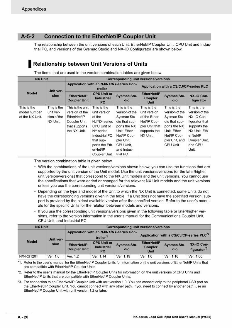
Appendices
A - 20 NX-series Load Cell Input Unit User’s Manual (W565)
The relationship between the unit versions of each Unit, EtherNet/IP Coupler Unit, CPU Unit and Indus-trial PC, and versions of the Sysmac Studio and NX-IO Configurator are shown below.
The items that are used in the version combination tables are given below.
The version combination table is given below.
• With the combinations of the unit versions/versions shown below, you can use the functions that are supported by the unit version of the Unit model. Use the unit versions/versions (or the later/higher unit version/versions) that correspond to the NX Unit models and the unit versions. You cannot use the specifications that were added or changed for the relevant NX Unit models and the unit versions unless you use the corresponding unit versions/versions.
• Depending on the type and model of the Unit to which the NX Unit is connected, some Units do not have the corresponding versions given in the table. If a Unit does not have the specified version, sup-port is provided by the oldest available version after the specified version. Refer to the user’s manu-als for the specific Units for the relation between models and versions.
• If you use the corresponding unit versions/versions given in the following table or later/higher ver-sions, refer to the version information in the user’s manual for the Communications Coupler Unit, CPU Unit, and Industrial PC.
A-5-2 Connection to the EtherNet/IP Coupler Unit
Relationship between Unit Versions of Units
NX Unit Corresponding unit versions/versions
ModelUnit ver-
sion
Application with an NJ/NX/NY-series Con-troller
Application with a CS/CJ/CP-series PLC
EtherNet/IP Coupler Unit
CPU Unit or Industrial
PC
Sysmac Stu-dio
EtherNet/IP Coupler
Unit
Sysmac Stu-dio
NX-IO Con-figurator
This is the model number of the NX Unit.
This is the unit ver-sion of the NX Unit.
This is the unit version of the EtherNet/IP Coupler Unit that supports the NX Unit.
This is the unit version of the NJ/NX-series CPU Unit or NY-series Industrial PC that sup-ports the Eth-erNet/IP Coupler Unit.
This is the version of the Sysmac Stu-dio that sup-ports the NX Unit, Ether-Net/IP Cou-pler Unit, CPU Unit, and Indus-trial PC.
This is the unit version of the Ether-Net/IP Cou-pler Unit that supports the NX Unit.
This is the version of the Sysmac Stu-dio that sup-ports the NX Unit, Ether-Net/IP Cou-pler Unit, and CPU Unit.
This is the version of the NX-IO Con-figurator that supports the NX Unit, Eth-erNet/IP Coupler Unit, and CPU Unit.
NX Unit Corresponding unit versions/versions
ModelUnit ver-
sion
Application with an NJ/NX/NY-series Con-
troller*1
*1. Refer to the user’s manual for the EtherNet/IP Coupler Units for information on the unit versions of EtherNet/IP Units that are compatible with EtherNet/IP Coupler Units.
Application with a CS/CJ/CP-series PLC*2
*2. Refer to the user’s manual for the EtherNet/IP Coupler Units for information on the unit versions of CPU Units and EtherNet/IP Units that are compatible with EtherNet/IP Coupler Units.
EtherNet/IP Coupler Unit
CPU Unit or Industrial
PC
Sysmac Stu-dio
EtherNet/IP Coupler
Unit
Sysmac Stu-dio
NX-IO Con-
figurator*3
*3. For connection to an EtherNet/IP Coupler Unit with unit version 1.0, You can connect only to the peripheral USB port on the EtherNet/IP Coupler Unit. You cannot connect with any other path. If you need to connect by another path, use an EtherNet/IP Coupler Unit with unit version 1.2 or later.
NX-RS1201 Ver. 1.0 Ver. 1.2 Ver. 1.14 Ver. 1.19 Ver. 1.0 Ver. 1.16 Ver. 1.00
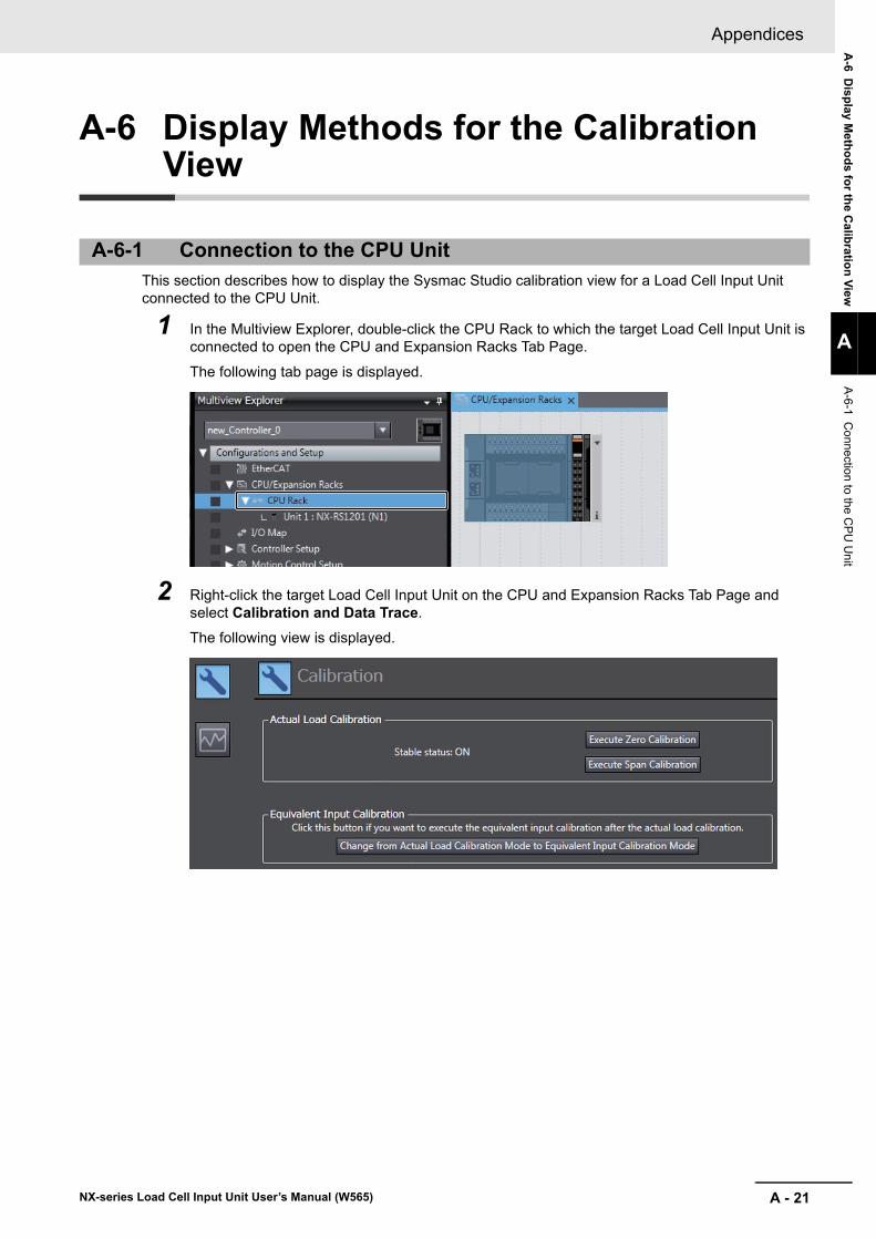
A - 21
Appendices
NX-series Load Cell Input Unit User’s Manual (W565)
A-6 D
isp
lay Meth
od
s for th
e Calib
ratio
n V
iew
A
A-6-1 C
onnection to
the CP
U U
nit
A-6 Display Methods for the Calibration View
This section describes how to display the Sysmac Studio calibration view for a Load Cell Input Unit connected to the CPU Unit.
1 In the Multiview Explorer, double-click the CPU Rack to which the target Load Cell Input Unit is connected to open the CPU and Expansion Racks Tab Page.
The following tab page is displayed.
2 Right-click the target Load Cell Input Unit on the CPU and Expansion Racks Tab Page and select Calibration and Data Trace.
The following view is displayed.
A-6-1 Connection to the CPU Unit
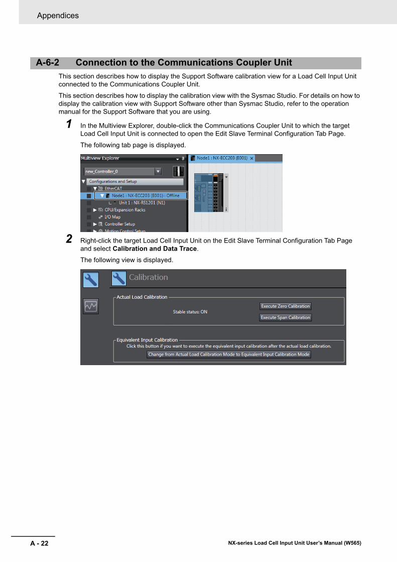
Appendices
A - 22 NX-series Load Cell Input Unit User’s Manual (W565)
This section describes how to display the Support Software calibration view for a Load Cell Input Unit connected to the Communications Coupler Unit.
This section describes how to display the calibration view with the Sysmac Studio. For details on how to display the calibration view with Support Software other than Sysmac Studio, refer to the operation manual for the Support Software that you are using.
1 In the Multiview Explorer, double-click the Communications Coupler Unit to which the target Load Cell Input Unit is connected to open the Edit Slave Terminal Configuration Tab Page.
The following tab page is displayed.
2 Right-click the target Load Cell Input Unit on the Edit Slave Terminal Configuration Tab Page and select Calibration and Data Trace.
The following view is displayed.
A-6-2 Connection to the Communications Coupler Unit
I - 1
I
NX-series Load Cell Input Unit User’s Manual (W565)
Index
I - 2 NX-series Load Cell Input Unit User’s Manual (W565)
Index
Index
A
access ............................................................................A-7Applicable Wires ............................................................. 4-4assumed cause .............................................................. 9-7attenuation characteristics ....................................... 8-7, 8-9
B
Bottom Hold Value DINT .............................................. 6-19Bottom Hold Value REAL ............................................. 6-20built-in EtherCAT port ...................................................... 11
C
Calibration Command ................................................... 6-23Calibration Command Response ................................. 6-21Calibration Command Response SID .......................... 6-20Calibration Command SID ............................................ 6-23Calibration Data ............................................................ 6-24Coding Pin .................................................................... 4-16Communications Coupler Unit ........................................ 1-5Communications Master Unit ......................................... 5-3CPU Rack ....................................................................... 1-5CPU Unit ........................................................................ 5-3crimping tool ................................................................... 4-5current error .................................................................... 9-5cutoff frequency .............................................................. 8-6
D
data attribute ..................................................................A-7data range ......................................................................A-7data type .........................................................................A-7DC is enabled ................................................................. 5-6default .............................................................................A-7Detection Status ........................................................... 6-15digital low-pass filter ....................................................... 8-6DIN Track contact plate .................................................. 3-2DIN Track mounting hook ............................................... 3-2
E
error descriptions .......................................................... 9-11event code ...................................................................... 9-7event name ..................................................................... 9-7Executing Status .......................................................... 6-16
F
Ferrule ............................................................................ 4-5fixed tare ......................................................................... 6-4
G
gross weight value ......................................................... 6-4Gross Weight Value/Force Measurement Value DINT . 6-17Gross Weight Value/Force Measurement Value REAL 6-18Ground terminal ...................................................... 4-5, 4-6ground terminal mark ..................................................... 3-5
I
I/O allocation ..................................................................A-7I/O allocation information ............................................. 6-13I/O allocation setting ..................................................... 6-13I/O entry ....................................................................... 6-13I/O entry mapping ......................................................... 6-13I/O Map ........................................................................ 4-19I/O power supply ............................................................ 4-3incorrect attachment prevention hole ........................... 4-16index ...............................................................................A-7indicator .......................................................................... 3-2Industrial PC .................................................................... 11
L
log of past error .............................................................. 9-6
M
marker attachment location ............................................ 3-2model number indication ................................................ 3-3moving average count .................................................... 8-9moving average filter ...................................................... 8-8
N
net weight value ............................................................. 6-4Net Weight Value DINT ................................................ 6-18Net Weight Value REAL ............................................... 6-18NX bus connector ........................................................... 3-2NX Unit power supply ..................................................... 4-3
O
object name ....................................................................A-7Operation Command .................................................... 6-22operation for task period prioritized refreshing ............. 5-13operation of Free-Run refreshing ................................... 5-8operation of synchronous I/O refreshing ........................ 5-9output characteristics of the load cell ............................. 6-3overview of the load cell ................................................. 6-2
I - 3NX-series Load Cell Input Unit User’s Manual (W565)
Index
I
P
Peak Hold Value DINT ..................................................6-19Peak Hold Value REAL .................................................6-19periodic inspection item ................................................10-3press fitting system .........................................................1-9Preventing Incorrect Attachment ...................................4-16protrusions for removing the Unit ....................................3-2
Q
quantitative discharging control system ..........................1-8
R
refresh cycle of the NX bus ..................................... 5-2, 5-3release hole ....................................................................3-5
S
scaling system ................................................................1-7securing wire .................................................................4-11shield .............................................................................4-20Slave Terminal ................................................................1-5Solid Wire ........................................................................4-6step response characteristics ................................. 8-7, 8-9subindex ......................................................................... A-7summing box .................................................................4-23Sync0 ............................................................................5-11synchronization timing ....................................................5-9
T
tare ..................................................................................6-4terminal block ..................................................................3-2terminal hole ...................................................................3-5terminal number indication ..............................................3-5timing to read inputs ........................................................5-8timing to refresh outputs .................................................5-8TS indicator .....................................................................3-3Twisted Wire ...................................................................4-6
U
unit ................................................................................. A-7Unit hookup guides .........................................................3-2unit specifications ............................................................3-2
W
warm-up ..........................................................................7-3Watch Tab Page ............................................................4-19Weighing Control Library ................................................2-7Wiring Terminals .............................................................4-4

I - 4 NX-series Load Cell Input Unit User’s Manual (W565)
Index


Authorized Distributor:
In the interest of product improvement, specifications are subject to change without notice.
Cat. No. W565-E1-05 1018
© OMRON Corporation 2016-2018 All Rights Reserved.
OMRON Corporation Industrial Automation Company
OMRON ELECTRONICS LLC2895 Greenspoint Parkway, Suite 200 Hoffman Estates, IL 60169 U.S.A.Tel: (1) 847-843-7900/Fax: (1) 847-843-7787
Regional HeadquartersOMRON EUROPE B.V.Wegalaan 67-69, 2132 JD HoofddorpThe NetherlandsTel: (31)2356-81-300/Fax: (31)2356-81-388
Contact: www.ia.omron.comKyoto, JAPAN
OMRON ASIA PACIFIC PTE. LTD.No. 438A Alexandra Road # 05-05/08 (Lobby 2), Alexandra Technopark, Singapore 119967Tel: (65) 6835-3011/Fax: (65) 6835-2711
OMRON (CHINA) CO., LTD.Room 2211, Bank of China Tower, 200 Yin Cheng Zhong Road, PuDong New Area, Shanghai, 200120, ChinaTel: (86) 21-5037-2222/Fax: (86) 21-5037-2200

![051224 - Nipron · 051224 - 6 - Model ePCSA-500P-X2S Item Efficiency at AC Input at AC Input Input Efficiency [%] Voltage [V] 50% Load 100% Load 85V AC 71.83 71.35](https://img.pdfslide.us/doc/110x75/6040066dbeaefa3a96117276/051224-051224-6-model-epcsa-500p-x2s-item-efficiency-at-ac-input-at-ac-input.jpg)