Embed Size (px)
Citation preview
CSM_NX-EC0____DS_E_5_1
1
NX-series Incremental Encoder Input Unit
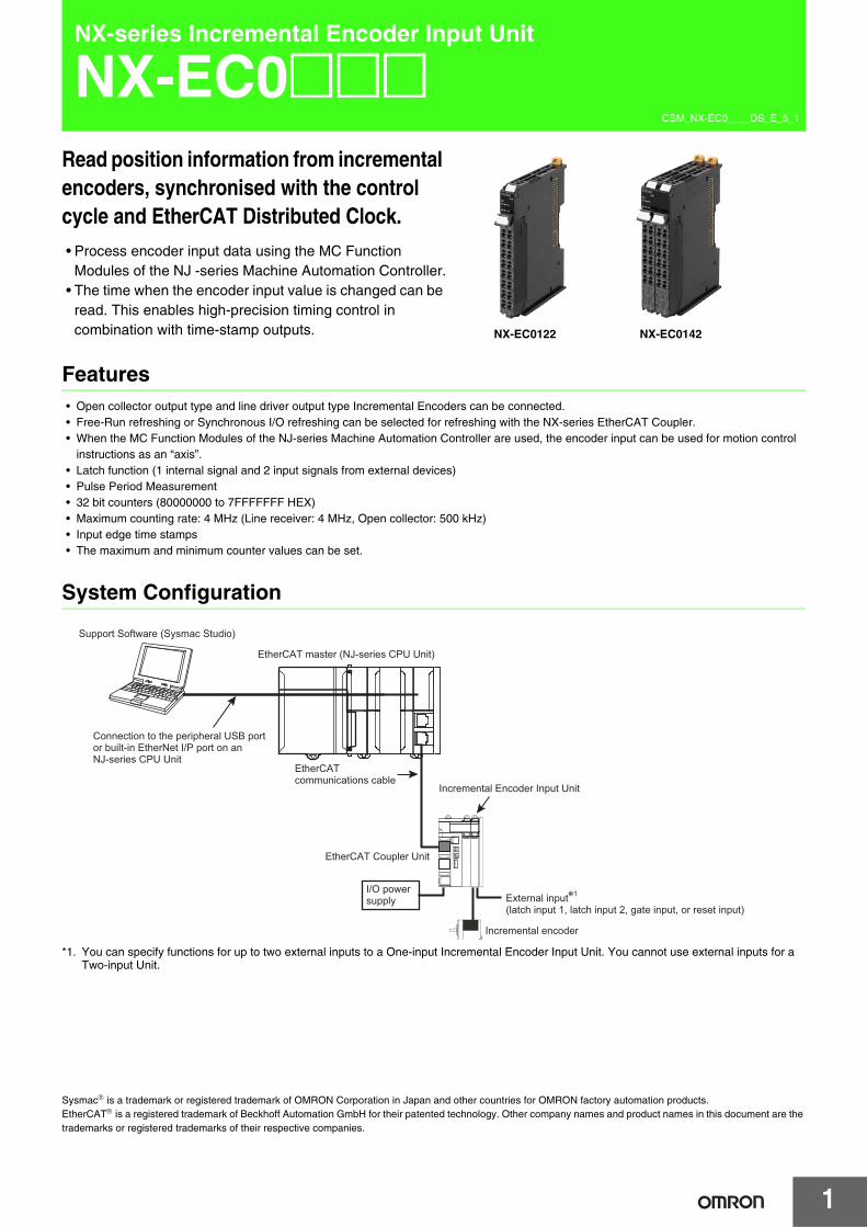
NX-EC0@@@Read position information from incremental encoders, synchronised with the control cycle and EtherCAT Distributed Clock.• Process encoder input data using the MC Function
Modules of the NJ -series Machine Automation Controller.• The time when the encoder input value is changed can be
read. This enables high-precision timing control in combination with time-stamp outputs.
Features• Open collector output type and line driver output type Incremental Encoders can be connected.• Free-Run refreshing or Synchronous I/O refreshing can be selected for refreshing with the NX-series EtherCAT Coupler.• When the MC Function Modules of the NJ-series Machine Automation Controller are used, the encoder input can be used for motion control
instructions as an “axis”.• Latch function (1 internal signal and 2 input signals from external devices)• Pulse Period Measurement• 32 bit counters (80000000 to 7FFFFFFF HEX)• Maximum counting rate: 4 MHz (Line receiver: 4 MHz, Open collector: 500 kHz)• Input edge time stamps• The maximum and minimum counter values can be set.
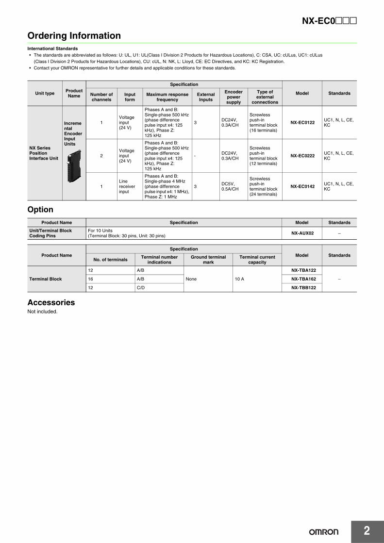
System Configuration
*1. You can specify functions for up to two external inputs to a One-input Incremental Encoder Input Unit. You cannot use external inputs for a Two-input Unit.
Sysmac® is a trademark or registered trademark of OMRON Corporation in Japan and other countries for OMRON factory automation products.EtherCAT® is a registered trademark of Beckhoff Automation GmbH for their patented technology. Other company names and product names in this document are the trademarks or registered trademarks of their respective companies.
NX-EC0122 NX-EC0142
EtherCAT master (NJ-series CPU Unit)
EtherCAT communications cable
EtherCAT Coupler Unit
Incremental Encoder Input Unit
External input*1
(latch input 1, latch input 2, gate input, or reset input)
Incremental encoder
Support Software (Sysmac Studio)
Connection to the peripheral USB port or built-in EtherNet I/P port on an NJ-series CPU Unit
I/O power supply
NX-EC0@@@
2
Ordering InformationInternational Standards• The standards are abbreviated as follows: U: UL, U1: UL(Class I Division 2 Products for Hazardous Locations), C: CSA, UC: cULus, UC1: cULus
(Class I Division 2 Products for Hazardous Locations), CU: cUL, N: NK, L: Lloyd, CE: EC Directives, and KC: KC Registration.• Contact your OMRON representative for further details and applicable conditions for these standards.
Option
AccessoriesNot included.
Unit type Product Name
Specification
Model StandardsNumber of channels
Input form
Maximum response frequency
External Inputs
Encoder power supply
Type of external
connections
NX Series Position Interface Unit
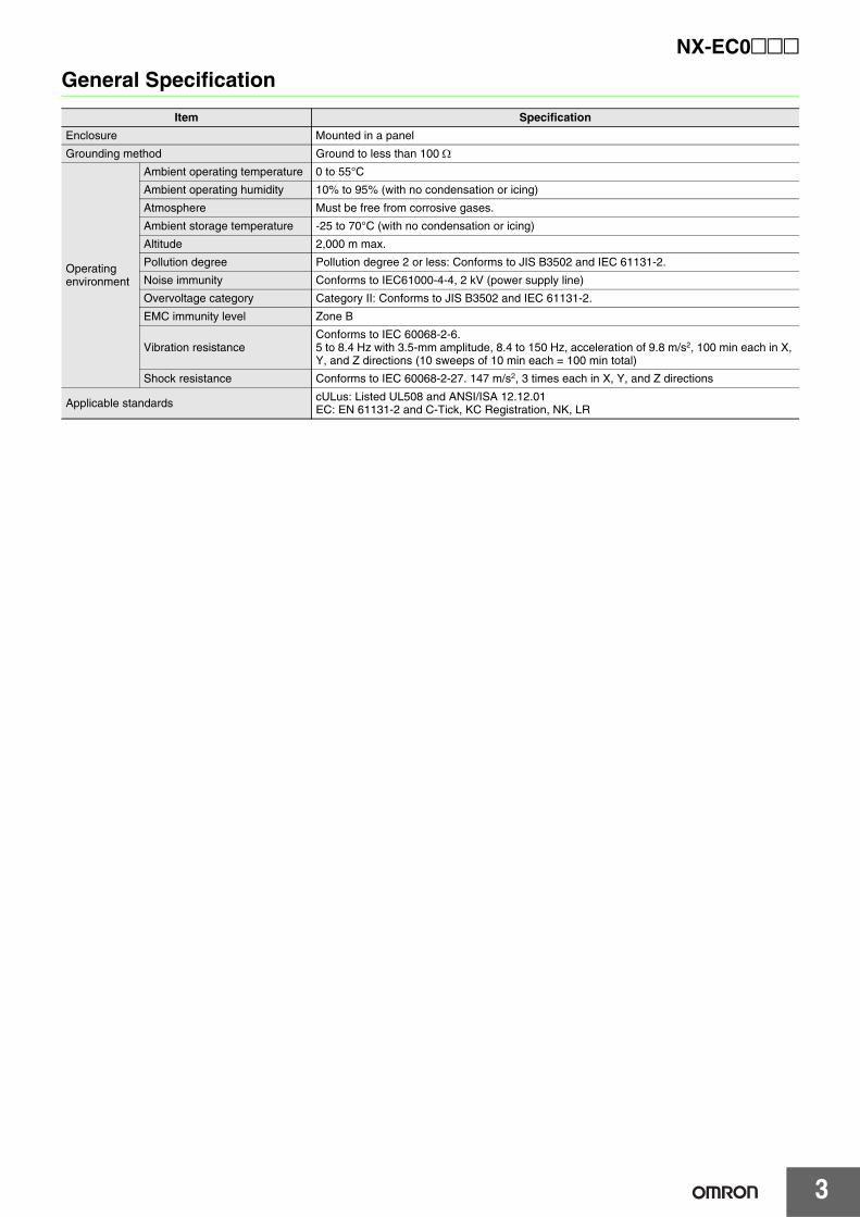
Incremental Encoder Input Units
1Voltage input (24 V)
Phases A and B: Single-phase 500 kHz (phase difference pulse input x4: 125 kHz), Phase Z:125 kHz
3DC24V, 0.3A/CH
Screwless push-in terminal block(16 terminals)
NX-EC0122 UC1, N, L, CE, KC
2Voltage input (24 V)
Phases A and B: Single-phase 500 kHz (phase difference pulse input x4: 125 kHz), Phase Z:125 kHz
-DC24V, 0.3A/CH
Screwless push-in terminal block(12 terminals)
NX-EC0222 UC1, N, L, CE, KC
1Line receiver input
Phases A and B: Single-phase 4 MHz (phase difference pulse input x4: 1 MHz), Phase Z: 1 MHz
3 DC5V, 0.5A/CH
Screwless push-in terminal block(24 terminals)
NX-EC0142 UC1, N, L, CE, KC
Product Name Specification Model Standards
Unit/Terminal Block Coding Pins
For 10 Units(Terminal Block: 30 pins, Unit: 30 pins) NX-AUX02 −
Product NameSpecification
Model StandardsNo. of terminals Terminal number
indicationsGround terminal
markTerminal current
capacity
Terminal Block
12 A/B
None 10 A
NX-TBA122
−16 A/B NX-TBA162
12 C/D NX-TBB122
3
NX-EC0@@@
General Specification
Item Specification
Enclosure Mounted in a panel
Grounding method Ground to less than 100 Ω
Operating environment
Ambient operating temperature 0 to 55°C
Ambient operating humidity 10% to 95% (with no condensation or icing)
Atmosphere Must be free from corrosive gases.
Ambient storage temperature -25 to 70°C (with no condensation or icing)
Altitude 2,000 m max.
Pollution degree Pollution degree 2 or less: Conforms to JIS B3502 and IEC 61131-2.
Noise immunity Conforms to IEC61000-4-4, 2 kV (power supply line)
Overvoltage category Category II: Conforms to JIS B3502 and IEC 61131-2.
EMC immunity level Zone B
Vibration resistanceConforms to IEC 60068-2-6.5 to 8.4 Hz with 3.5-mm amplitude, 8.4 to 150 Hz, acceleration of 9.8 m/s2, 100 min each in X, Y, and Z directions (10 sweeps of 10 min each = 100 min total)
Shock resistance Conforms to IEC 60068-2-27. 147 m/s2, 3 times each in X, Y, and Z directions
Applicable standards cULus: Listed UL508 and ANSI/ISA 12.12.01EC: EN 61131-2 and C-Tick, KC Registration, NK, LR
NX-EC0@@@
4
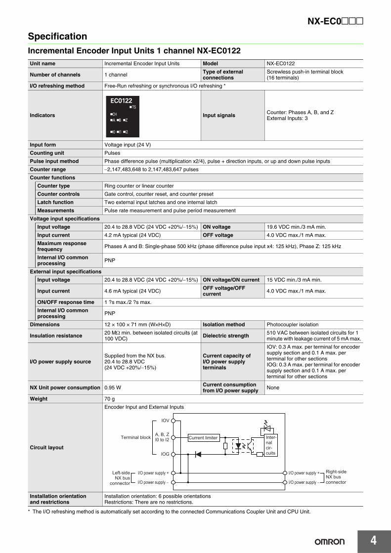
SpecificationIncremental Encoder Input Units 1 channel NX-EC0122
* The I/O refreshing method is automatically set according to the connected Communications Coupler Unit and CPU Unit.
Unit name Incremental Encoder Input Units Model NX-EC0122
Number of channels 1 channel Type of external connections
Screwless push-in terminal block(16 terminals)
I/O refreshing method Free-Run refreshing or synchronous I/O refreshing *
Indicators Input signals Counter: Phases A, B, and ZExternal Inputs: 3
Input form Voltage input (24 V)
Counting unit Pulses
Pulse input method Phase difference pulse (multiplication x2/4), pulse + direction inputs, or up and down pulse inputs
Counter range −2,147,483,648 to 2,147,483,647 pulses
Counter functions
Counter type Ring counter or linear counter
Counter controls Gate control, counter reset, and counter preset
Latch function Two external input latches and one internal latch
Measurements Pulse rate measurement and pulse period measurement
Voltage input specifications
Input voltage 20.4 to 28.8 VDC (24 VDC +20%/−15%) ON voltage 19.6 VDC min./3 mA min.
Input current 4.2 mA typical (24 VDC) OFF voltage 4.0 VDC max./1 mA max.
Maximum response frequency Phases A and B: Single-phase 500 kHz (phase difference pulse input x4: 125 kHz), Phase Z: 125 kHz
Internal I/O common processing PNP
External input specifications
Input voltage 20.4 to 28.8 VDC (24 VDC +20%/−15%) ON voltage/ON current 15 VDC min./3 mA min.
Input current 4.6 mA typical (24 VDC) OFF voltage/OFF current 4.0 VDC max./1 mA max.
ON/OFF response time 1 ?s max./2 ?s max.
Internal I/O common processing PNP
Dimensions 12 × 100 × 71 mm (W×H×D) Isolation method Photocoupler isolation
Insulation resistance 20 MΩ min. between isolated circuits (at 100 VDC) Dielectric strength 510 VAC between isolated circuits for 1
minute with leakage current of 5 mA max.
I/O power supply sourceSupplied from the NX bus.20.4 to 28.8 VDC(24 VDC +20%/−15%)
Current capacity of I/O power supply terminals
IOV: 0.3 A max. per terminal for encoder supply section and 0.1 A max. per terminal for other sectionsIOG: 0.3 A max. per terminal for encoder supply section and 0.1 A max. per terminal for other sections
NX Unit power consumption 0.95 W Current consumption from I/O power supply None
Weight 70 g
Circuit layout
Encoder Input and External Inputs
Installation orientationand restrictions
Installation orientation: 6 possible orientationsRestrictions: There are no restrictions.
A, B, ZI0 to I2
IOG
Current limiter
IOV
I/O power supply +
I/O power supply −
I/O power supply +
I/O power supply −
Terminal block
Left-side NX bus
connector
Right-side NX bus connector
Inter-nal cir-cuits
5
NX-EC0@@@
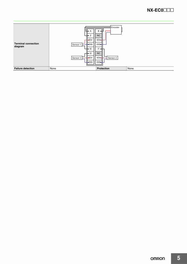
Terminal connectiondiagram
Failure detection None Protection None
A
Z
IOV
IOG
I0
I2
B
NC
IOV
IOG
I1
NC
IOG IOG
IOV IOV
Sensor 1
Sensor 2Sensor 3
Encoder
NX-EC0@@@
6
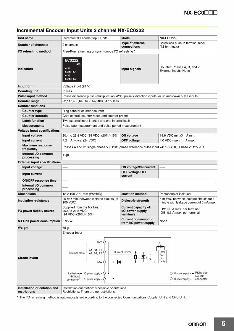
Incremental Encoder Input Units 2 channel NX-EC0222
* The I/O refreshing method is automatically set according to the connected Communications Coupler Unit and CPU Unit.
Unit name Incremental Encoder Input Units Model NX-EC0222
Number of channels 2 channels Type of external connections
Screwless push-in terminal block(12 terminals)
I/O refreshing method Free-Run refreshing or synchronous I/O refreshing *
Indicators Input signals Counter: Phases A, B, and ZExternal Inputs: None
Input form Voltage input (24 V)
Counting unit Pulses
Pulse input method Phase difference pulse (multiplication x2/4), pulse + direction inputs, or up and down pulse inputs
Counter range −2,147,483,648 to 2,147,483,647 pulses
Counter functions
Counter type Ring counter or linear counter
Counter controls Gate control, counter reset, and counter preset
Latch function Two external input latches and one internal latch
Measurements Pulse rate measurement and pulse period measurement
Voltage input specifications
Input voltage 20.4 to 28.8 VDC (24 VDC +20%/−15%) ON voltage 19.6 VDC min./3 mA min.
Input current 4.2 mA typical (24 VDC) OFF voltage 4.0 VDC max./1 mA max.
Maximum response frequency Phases A and B: Single-phase 500 kHz (phase difference pulse input x4: 125 kHz), Phase Z: 125 kHz
Internal I/O common processing PNP
External input specifications
Input voltage −−− ON voltage/ON current −−−
Input current −−− OFF voltage/OFF current −−−
ON/OFF response time −−−
Internal I/O common processing −−−
Dimensions 12 × 100 × 71 mm (W×H×D) Isolation method Photocoupler isolation
Insulation resistance 20 MΩ min. between isolated circuits (at 100 VDC) Dielectric strength 510 VAC between isolated circuits for 1
minute with leakage current of 5 mA max.
I/O power supply sourceSupplied from the NX bus.20.4 to 28.8 VDC(24 VDC +20%/−15%)
Current capacity of I/O power supply terminals
IOV: 0.3 A max. per terminalIOG: 0.3 A max. per terminal
NX Unit power consumption 0.95 W Current consumption from I/O power supply None
Weight 65 g
Circuit layout
Encoder Input
Installation orientation and restrictions
Installation orientation: 6 possible orientationsRestrictions: There are no restrictions.
Inter-nal cir-cuits
Current limiter
IOV
A1, B1, Z1A2, B2, Z2
IOG
I/O power supply +
I/O power supply −
I/O power supply +
I/O power supply −
Terminal block
Left-side NX bus
connector
Right-side NX bus connector
7
NX-EC0@@@
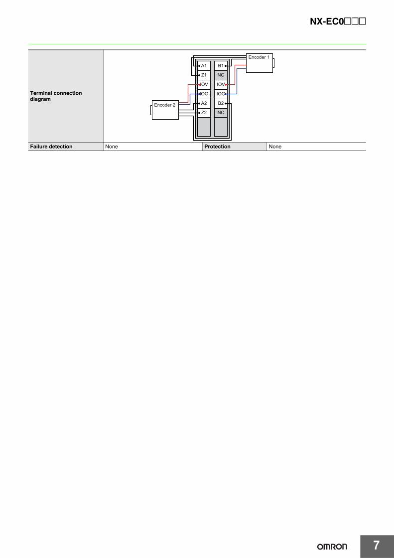
Terminal connection diagram
Failure detection None Protection None
Encoder 1
Encoder 2
A1
Z1
IOV
IOG
A2
Z2
B1
NC
IOV
IOG
B2
NC
NX-EC0@@@
8
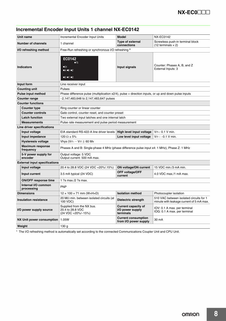
Incremental Encoder Input Units 1 channel NX-EC0142
* The I/O refreshing method is automatically set according to the connected Communications Coupler Unit and CPU Unit.
Unit name Incremental Encoder Input Units Model NX-EC0142
Number of channels 1 channel Type of external connections
Screwless push-in terminal block(12 terminals × 2)
I/O refreshing method Free-Run refreshing or synchronous I/O refreshing *
Indicators Input signals Counter: Phases A, B, and ZExternal Inputs: 3
Input form Line receiver input
Counting unit Pulses
Pulse input method Phase difference pulse (multiplication x2/4), pulse + direction inputs, or up and down pulse inputs
Counter range −2,147,483,648 to 2,147,483,647 pulses
Counter functions
Counter type Ring counter or linear counter
Counter controls Gate control, counter reset, and counter preset
Latch function Two external input latches and one internal latch
Measurements Pulse rate measurement and pulse period measurement
Line driver specifications
Input voltage EIA standard RS-422-A line driver levels High level input voltage VIT+: 0.1 V min.
Input impedance 120 Ω ± 5% Low level input voltage VIT−: −0.1 V min.
Hysteresis voltage Vhys (VIT+ − VIT−): 60 Mv
Maximum response frequency Phases A and B: Single-phase 4 MHz (phase difference pulse input x4: 1 MHz), Phase Z: 1 MHz
5-V power supply for encoder
Output voltage: 5 VDCOutput current: 500 mA max.
External input specifications
Input voltage 20.4 to 28.8 VDC (24 VDC +20%/.15%) ON voltage/ON current 15 VDC min./3 mA min.
Input current 3.5 mA typical (24 VDC) OFF voltage/OFF current 4.0 VDC max./1 mA max.
ON/OFF response time 1 ?s max./2 ?s max.
Internal I/O common processing PNP
Dimensions 12 × 100 × 71 mm (W×H×D) Isolation method Photocoupler isolation
Insulation resistance 20 MΩ min. between isolated circuits (at 100 VDC) Dielectric strength 510 VAC between isolated circuits for 1
minute with leakage current of 5 mA max.
I/O power supply sourceSupplied from the NX bus.20.4 to 28.8 VDC(24 VDC +20%/−15%)
Current capacity of I/O power supply terminals
IOV: 0.1 A max. per terminalIOG: 0.1 A max. per terminal
NX Unit power consumption 1.05W Current consumption from I/O power supply 30 mA
Weight 130 g
9
NX-EC0@@@
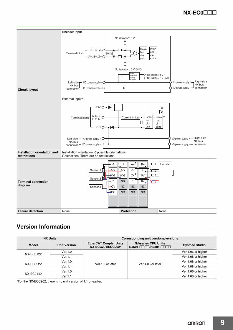
Version Information
*For the NX-ECC202, there is no unit version of 1.1 or earlier.
Circuit layout
Encoder Input
External Inputs
Installation orientation and restrictions
Installation orientation: 6 possible orientationsRestrictions: There are no restrictions.
Terminal connection diagram
Failure detection None Protection None
NX Units Corresponding unit versions/versions
Model Unit Version EtherCAT Coupler Units NX-ECC201/ECC202*
NJ-series CPU UnitsNJ501-@@@@/NJ301-@@@@ Sysmac Studio
NX-EC0122Ver.1.0
Ver.1.0 or later Ver.1.05 or later
Ver.1.06 or higher
Ver.1.1 Ver.1.08 or higher
NX-EC0222Ver.1.0 Ver.1.06 or higher
Ver.1.1 Ver.1.08 or higher
NX-EC0142Ver.1.0 Ver.1.06 or higher
Ver.1.1 Ver.1.08 or higher
120 ΩA-, B-, Z-
A+, B+, Z+
No isolation: 5 V GND
No isolation: 5 VNo isolation: 5 V GND
Terminal blockIsola-tion cir-cuit
No isolation: 5 V
Non-isolated power supply
Inter-nal cir-cuits
I/O power supply +
I/O power supply −
I/O power supply +
I/O power supply −
Left-side NX bus
connector
Right-side NX bus connector
A, B, ZI0 to I2
Inter-nal cir-cuits
Power
IOG
IOV
I/O power supply +
I/O power supply −
I/O power supply +
I/O power supply −
Terminal block
Left-side NX bus
connector
Right-side NX bus connector
Isola-tion cir-cuit
Current limiter
I0
IOV
IOG
I1 A+
A-
Z+
Z-
B+
B-
5V
0V
IOV
IOG
I2
IOV
IOG
NC
NC
NC
NC
NC
NC
NC
Sensor 1
Sensor 2
Sensor 3
Encoder
NX-EC0@@@
10
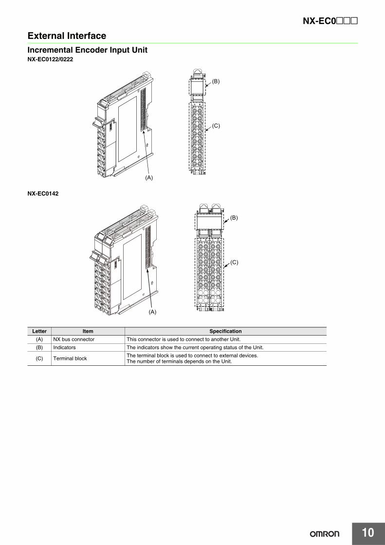
External InterfaceIncremental Encoder Input UnitNX-EC0122/0222
NX-EC0142
Letter Item Specification
(A) NX bus connector This connector is used to connect to another Unit.
(B) Indicators The indicators show the current operating status of the Unit.
(C) Terminal block The terminal block is used to connect to external devices.The number of terminals depends on the Unit.
(A)
(C)
(B)
(C)
(B)
(A)
11
NX-EC0@@@
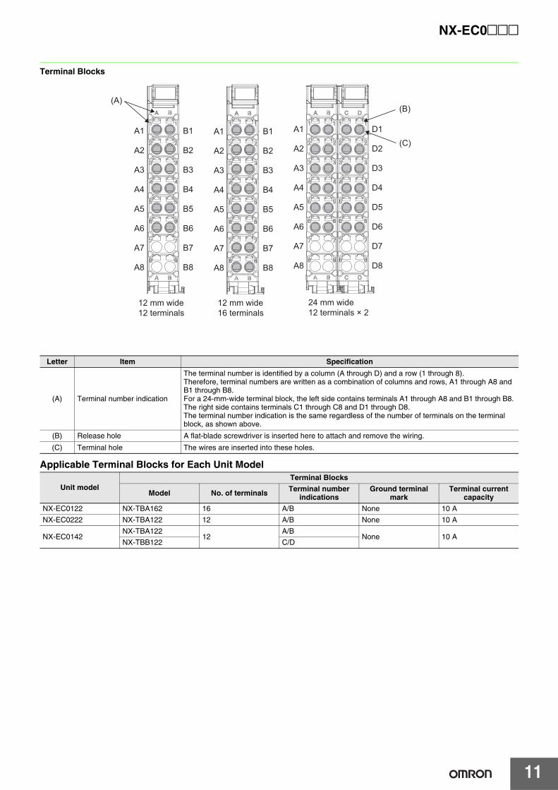
Terminal Blocks
Applicable Terminal Blocks for Each Unit Model
Letter Item Specification
(A) Terminal number indication
The terminal number is identified by a column (A through D) and a row (1 through 8).Therefore, terminal numbers are written as a combination of columns and rows, A1 through A8 and B1 through B8.For a 24-mm-wide terminal block, the left side contains terminals A1 through A8 and B1 through B8. The right side contains terminals C1 through C8 and D1 through D8.The terminal number indication is the same regardless of the number of terminals on the terminal block, as shown above.
(B) Release hole A flat-blade screwdriver is inserted here to attach and remove the wiring.
(C) Terminal hole The wires are inserted into these holes.
Unit modelTerminal Blocks
Model No. of terminals Terminal number indications
Ground terminal mark
Terminal current capacity
NX-EC0122 NX-TBA162 16 A/B None 10 A
NX-EC0222 NX-TBA122 12 A/B None 10 A
NX-EC0142NX-TBA122
12A/B
None 10 ANX-TBB122 C/D
(B)
(C)A1
A2
A3
A4
A5
A6
A7
A8
D1
D2
D3
D4
D5
D6
D7
D8
A1
A2
A3
A4
A5
A6
A7
A8
B1
B2
B3
B4
B5
B6
B7
B8
A1
A2
A3
A4
A5
A6
A7
A8
B1
B2
B3
B4
B5
B6
B7
B8
24 mm wide12 terminals × 2
12 mm wide16 terminals
12 mm wide12 terminals
(A)C D
C D
A BA BA B
NX-EC0@@@
12
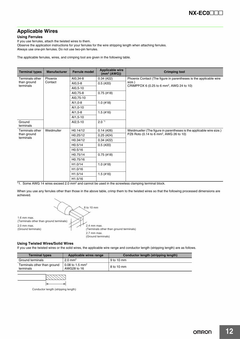
Applicable WiresUsing FerrulesIf you use ferrules, attach the twisted wires to them.Observe the application instructions for your ferrules for the wire stripping length when attaching ferrules.Always use one-pin ferrules. Do not use two-pin ferrules.
The applicable ferrules, wires, and crimping tool are given in the following table.
*1. Some AWG 14 wires exceed 2.0 mm2 and cannot be used in the screwless clamping terminal block.
When you use any ferrules other than those in the above table, crimp them to the twisted wires so that the following processed dimensions are achieved.
Using Twisted Wires/Solid WiresIf you use the twisted wires or the solid wires, the applicable wire range and conductor length (stripping length) are as follows.
Terminal types Manufacturer Ferrule model Applicable wire(mm2 (AWG)) Crimping tool
Terminals other than ground terminals
Phoenix Contact
AI0,34-8 0.34 (#22) Phoenix Contact (The figure in parentheses is the applicable wire size.)CRIMPFOX 6 (0.25 to 6 mm2, AWG 24 to 10)
AI0,5-8 0.5 (#20)
AI0,5-10
AI0,75-8 0.75 (#18)
AI0,75-10
AI1,0-8 1.0 (#18)
AI1,0-10
AI1,5-8 1.5 (#16)
AI1,5-10
Ground terminals
AI2,5-10 2.0 *1
Terminals other than ground terminals
Weidmuller H0.14/12 0.14 (#26) Weidmueller (The figure in parentheses is the applicable wire size.)PZ6 Roto (0.14 to 6 mm2, AWG 26 to 10)H0.25/12 0.25 (#24)
H0.34/12 0.34 (#22)
H0.5/14 0.5 (#20)
H0.5/16
H0.75/14 0.75 (#18)
H0.75/16
H1.0/14 1.0 (#18)
H1.0/16
H1.5/14 1.5 (#16)
H1.5/16
Terminal types Applicable wires range Conductor length (stripping length)
Ground terminals 2.0 mm2 9 to 10 mm
Terminals other than ground terminals
0.08 to 1.5 mm2
AWG28 to 16 8 to 10 mm
1.6 mm max.(Terminals other than ground terminals)2.0 mm max.(Ground terminals)
2.4 mm max.(Terminals other than ground terminals)2.7 mm max.(Ground terminals)
8 to 10 mm
Conductor length (stripping length)
13
NX-EC0@@@
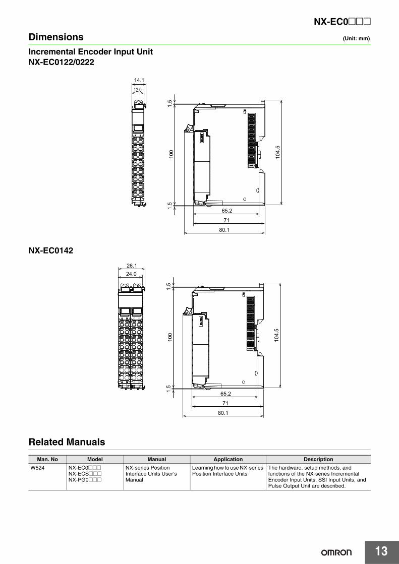
Dimensions (Unit: mm)
Incremental Encoder Input UnitNX-EC0122/0222
NX-EC0142
Related Manuals
Man. No Model Manual Application Description
W524 NX-EC0@@@NX-ECS@@@NX-PG0@@@
NX-series Position Interface Units User’s Manual
Learning how to use NX-series Position Interface Units
The hardware, setup methods, and functions of the NX-series Incremental Encoder Input Units, SSI Input Units, and Pulse Output Unit are described.
80.1
71
104.
5
100
14.1
65.2
12.0
1.5
1.5
26.124.0
C D
C D
80.1
71
104.
5
100
65.21.5
1.5
Terms and Conditions of Sale1. Offer; Acceptance. These terms and conditions (these "Terms") are deemed
part of all quotes, agreements, purchase orders, acknowledgments, price lists,catalogs, manuals, brochures and other documents, whether electronic or inwriting, relating to the sale of products or services (collectively, the "Products")by Omron Electronics LLC and its subsidiary companies (“Omron”). Omronobjects to any terms or conditions proposed in Buyer’s purchase order or otherdocuments which are inconsistent with, or in addition to, these Terms.
2. Prices; Payment Terms. All prices stated are current, subject to change with-out notice by Omron. Omron reserves the right to increase or decrease priceson any unshipped portions of outstanding orders. Payments for Products aredue net 30 days unless otherwise stated in the invoice.
3. Discounts. Cash discounts, if any, will apply only on the net amount of invoicessent to Buyer after deducting transportation charges, taxes and duties, and willbe allowed only if (i) the invoice is paid according to Omron’s payment termsand (ii) Buyer has no past due amounts.
4. Interest. Omron, at its option, may charge Buyer 1-1/2% interest per month orthe maximum legal rate, whichever is less, on any balance not paid within thestated terms.
5. Orders. Omron will accept no order less than $200 net billing. 6. Governmental Approvals. Buyer shall be responsible for, and shall bear all
costs involved in, obtaining any government approvals required for the impor-tation or sale of the Products.
7. Taxes. All taxes, duties and other governmental charges (other than generalreal property and income taxes), including any interest or penalties thereon,imposed directly or indirectly on Omron or required to be collected directly orindirectly by Omron for the manufacture, production, sale, delivery, importa-tion, consumption or use of the Products sold hereunder (including customsduties and sales, excise, use, turnover and license taxes) shall be charged toand remitted by Buyer to Omron.
8. Financial. If the financial position of Buyer at any time becomes unsatisfactoryto Omron, Omron reserves the right to stop shipments or require satisfactorysecurity or payment in advance. If Buyer fails to make payment or otherwisecomply with these Terms or any related agreement, Omron may (without liabil-ity and in addition to other remedies) cancel any unshipped portion of Prod-ucts sold hereunder and stop any Products in transit until Buyer pays allamounts, including amounts payable hereunder, whether or not then due,which are owing to it by Buyer. Buyer shall in any event remain liable for allunpaid accounts.
9. Cancellation; Etc. Orders are not subject to rescheduling or cancellationunless Buyer indemnifies Omron against all related costs or expenses.
10. Force Majeure. Omron shall not be liable for any delay or failure in deliveryresulting from causes beyond its control, including earthquakes, fires, floods,strikes or other labor disputes, shortage of labor or materials, accidents tomachinery, acts of sabotage, riots, delay in or lack of transportation or therequirements of any government authority.
11. Shipping; Delivery. Unless otherwise expressly agreed in writing by Omron:a. Shipments shall be by a carrier selected by Omron; Omron will not drop ship
except in “break down” situations.b. Such carrier shall act as the agent of Buyer and delivery to such carrier shall
constitute delivery to Buyer;c. All sales and shipments of Products shall be FOB shipping point (unless oth-
erwise stated in writing by Omron), at which point title and risk of loss shallpass from Omron to Buyer; provided that Omron shall retain a security inter-est in the Products until the full purchase price is paid;
d. Delivery and shipping dates are estimates only; ande. Omron will package Products as it deems proper for protection against nor-
mal handling and extra charges apply to special conditions.12. Claims. Any claim by Buyer against Omron for shortage or damage to the
Products occurring before delivery to the carrier must be presented in writingto Omron within 30 days of receipt of shipment and include the original trans-portation bill signed by the carrier noting that the carrier received the Productsfrom Omron in the condition claimed.
13. Warranties. (a) Exclusive Warranty. Omron’s exclusive warranty is that theProducts will be free from defects in materials and workmanship for a period oftwelve months from the date of sale by Omron (or such other period expressedin writing by Omron). Omron disclaims all other warranties, express or implied.(b) Limitations. OMRON MAKES NO WARRANTY OR REPRESENTATION,EXPRESS OR IMPLIED, ABOUT NON-INFRINGEMENT, MERCHANTABIL-
ITY OR FITNESS FOR A PARTICULAR PURPOSE OF THE PRODUCTS.BUYER ACKNOWLEDGES THAT IT ALONE HAS DETERMINED THAT THEPRODUCTS WILL SUITABLY MEET THE REQUIREMENTS OF THEIRINTENDED USE. Omron further disclaims all warranties and responsibility ofany type for claims or expenses based on infringement by the Products or oth-erwise of any intellectual property right. (c) Buyer Remedy. Omron’s sole obli-gation hereunder shall be, at Omron’s election, to (i) replace (in the formoriginally shipped with Buyer responsible for labor charges for removal orreplacement thereof) the non-complying Product, (ii) repair the non-complyingProduct, or (iii) repay or credit Buyer an amount equal to the purchase price ofthe non-complying Product; provided that in no event shall Omron be responsi-ble for warranty, repair, indemnity or any other claims or expenses regardingthe Products unless Omron’s analysis confirms that the Products were prop-erly handled, stored, installed and maintained and not subject to contamina-tion, abuse, misuse or inappropriate modification. Return of any Products byBuyer must be approved in writing by Omron before shipment. Omron Compa-nies shall not be liable for the suitability or unsuitability or the results from theuse of Products in combination with any electrical or electronic components,circuits, system assemblies or any other materials or substances or environ-ments. Any advice, recommendations or information given orally or in writing,are not to be construed as an amendment or addition to the above warranty.See http://www.omron247.com or contact your Omron representative for pub-lished information.
14. Limitation on Liability; Etc. OMRON COMPANIES SHALL NOT BE LIABLEFOR SPECIAL, INDIRECT, INCIDENTAL, OR CONSEQUENTIAL DAMAGES,LOSS OF PROFITS OR PRODUCTION OR COMMERCIAL LOSS IN ANYWAY CONNECTED WITH THE PRODUCTS, WHETHER SUCH CLAIM ISBASED IN CONTRACT, WARRANTY, NEGLIGENCE OR STRICT LIABILITY.Further, in no event shall liability of Omron Companies exceed the individualprice of the Product on which liability is asserted.
15. Indemnities. Buyer shall indemnify and hold harmless Omron Companies andtheir employees from and against all liabilities, losses, claims, costs andexpenses (including attorney's fees and expenses) related to any claim, inves-tigation, litigation or proceeding (whether or not Omron is a party) which arisesor is alleged to arise from Buyer's acts or omissions under these Terms or inany way with respect to the Products. Without limiting the foregoing, Buyer (atits own expense) shall indemnify and hold harmless Omron and defend or set-tle any action brought against such Companies to the extent based on a claimthat any Product made to Buyer specifications infringed intellectual propertyrights of another party.
16. Property; Confidentiality. Any intellectual property in the Products is the exclu-sive property of Omron Companies and Buyer shall not attempt to duplicate itin any way without the written permission of Omron. Notwithstanding anycharges to Buyer for engineering or tooling, all engineering and tooling shallremain the exclusive property of Omron. All information and materials suppliedby Omron to Buyer relating to the Products are confidential and proprietary,and Buyer shall limit distribution thereof to its trusted employees and strictlyprevent disclosure to any third party.
17. Export Controls. Buyer shall comply with all applicable laws, regulations andlicenses regarding (i) export of products or information; (iii) sale of products to“forbidden” or other proscribed persons; and (ii) disclosure to non-citizens ofregulated technology or information.
18. Miscellaneous. (a) Waiver. No failure or delay by Omron in exercising any rightand no course of dealing between Buyer and Omron shall operate as a waiverof rights by Omron. (b) Assignment. Buyer may not assign its rights hereunderwithout Omron's written consent. (c) Law. These Terms are governed by thelaw of the jurisdiction of the home office of the Omron company from whichBuyer is purchasing the Products (without regard to conflict of law princi-ples). (d) Amendment. These Terms constitute the entire agreement betweenBuyer and Omron relating to the Products, and no provision may be changedor waived unless in writing signed by the parties. (e) Severability. If any provi-sion hereof is rendered ineffective or invalid, such provision shall not invalidateany other provision. (f) Setoff. Buyer shall have no right to set off any amountsagainst the amount owing in respect of this invoice. (g) Definitions. As usedherein, “including” means “including without limitation”; and “Omron Compa-nies” (or similar words) mean Omron Corporation and any direct or indirectsubsidiary or affiliate thereof.
Certain Precautions on Specifications and Use1. Suitability of Use. Omron Companies shall not be responsible for conformity
with any standards, codes or regulations which apply to the combination of theProduct in the Buyer’s application or use of the Product. At Buyer’s request,Omron will provide applicable third party certification documents identifyingratings and limitations of use which apply to the Product. This information byitself is not sufficient for a complete determination of the suitability of the Prod-uct in combination with the end product, machine, system, or other applicationor use. Buyer shall be solely responsible for determining appropriateness ofthe particular Product with respect to Buyer’s application, product or system.Buyer shall take application responsibility in all cases but the following is anon-exhaustive list of applications for which particular attention must be given:(i) Outdoor use, uses involving potential chemical contamination or electricalinterference, or conditions or uses not described in this document.(ii) Use in consumer products or any use in significant quantities. (iii) Energy control systems, combustion systems, railroad systems, aviationsystems, medical equipment, amusement machines, vehicles, safety equip-ment, and installations subject to separate industry or government regulations. (iv) Systems, machines and equipment that could present a risk to life or prop-erty. Please know and observe all prohibitions of use applicable to this Prod-uct. NEVER USE THE PRODUCT FOR AN APPLICATION INVOLVING SERIOUSRISK TO LIFE OR PROPERTY OR IN LARGE QUANTITIES WITHOUTENSURING THAT THE SYSTEM AS A WHOLE HAS BEEN DESIGNED TO
ADDRESS THE RISKS, AND THAT THE OMRON’S PRODUCT IS PROP-ERLY RATED AND INSTALLED FOR THE INTENDED USE WITHIN THEOVERALL EQUIPMENT OR SYSTEM.
2. Programmable Products. Omron Companies shall not be responsible for theuser’s programming of a programmable Product, or any consequence thereof.
3. Performance Data. Data presented in Omron Company websites, catalogsand other materials is provided as a guide for the user in determining suitabil-ity and does not constitute a warranty. It may represent the result of Omron’stest conditions, and the user must correlate it to actual application require-ments. Actual performance is subject to the Omron’s Warranty and Limitationsof Liability.
4. Change in Specifications. Product specifications and accessories may bechanged at any time based on improvements and other reasons. It is our prac-tice to change part numbers when published ratings or features are changed,or when significant construction changes are made. However, some specifica-tions of the Product may be changed without any notice. When in doubt, spe-cial part numbers may be assigned to fix or establish key specifications foryour application. Please consult with your Omron’s representative at any timeto confirm actual specifications of purchased Product.
5. Errors and Omissions. Information presented by Omron Companies has beenchecked and is believed to be accurate; however, no responsibility is assumedfor clerical, typographical or proofreading errors or omissions.
OMRON CANADA, INC. • HEAD OFFICEToronto, ON, Canada • 416.286.6465 • 866.986.6766 • www.omron247.com
OMRON ELECTRONICS DE MEXICO • HEAD OFFICEMéxico DF • 52.55.59.01.43.00 • 01-800-226-6766 • [email protected]
OMRON ELECTRONICS DE MEXICO • SALES OFFICEApodaca, N.L. • 52.81.11.56.99.20 • 01-800-226-6766 • [email protected]
OMRON ELETRÔNICA DO BRASIL LTDA • HEAD OFFICESão Paulo, SP, Brasil • 55.11.2101.6300 • www.omron.com.br
OMRON ARGENTINA • SALES OFFICECono Sur • 54.11.4783.5300
OMRON CHILE • SALES OFFICESantiago • 56.9.9917.3920
OTHER OMRON LATIN AMERICA SALES54.11.4783.5300
Authorized Distributor:
Note: Specifications are subject to change. © 2014 Omron Electronics LLC Printed in U.S.A.
Printed on recycled paper.
Automation Control Systems• Machine Automation Controllers (MAC) • Programmable Controllers (PLC) • Operator interfaces (HMI) • Distributed I/O • Software
Drives & Motion Controls • Servo & AC Drives • Motion Controllers & Encoders
Temperature & Process Controllers • Single and Multi-loop Controllers
Sensors & Vision• Proximity Sensors • Photoelectric Sensors • Fiber-Optic Sensors• Amplified Photomicrosensors • Measurement Sensors• Ultrasonic Sensors • Vision Sensors
Industrial Components • RFID/Code Readers • Relays • Pushbuttons & Indicators • Limit and Basic Switches • Timers • Counters • Metering Devices • Power Supplies
Safety • Laser Scanners • Safety Mats • Edges and Bumpers • Programmable Safety Controllers • Light Curtains • Safety Relays • Safety Interlock Switches
OMRON AUTOMATION AND SAFETY • THE AMERICAS HEADQUARTERS • Chicago, IL USA • 847.843.7900 • 800.556.6766 • www.omron247.com
OMRON EUROPE B.V. • Wegalaan 67-69, NL-2132 JD, Hoofddorp, The Netherlands. • +31 (0) 23 568 13 00 • www.industrial.omron.eu