Embed Size (px)
Citation preview
Load your NX drawing
template file.
Great than
MENU > INSERT > DESIGN
FEATURE > EXTRUDE
Choose the XZ plane of the
coordinate system.
Why choose this
orientation for our initial
sketch plane?
Create the following sketch as shown in the figure.
MENU > INSERT > DIMENSIONS > LINEAR
Apply dimensional constraints as shown.
Set the values as indicated.
If you have to return to a dimension to
edit its value, DBL Click on the dimension
value to open the edit window.
Why are the values for P11 and P12 set to
have equation values?
Middle Mouse Button (MMB) to end.
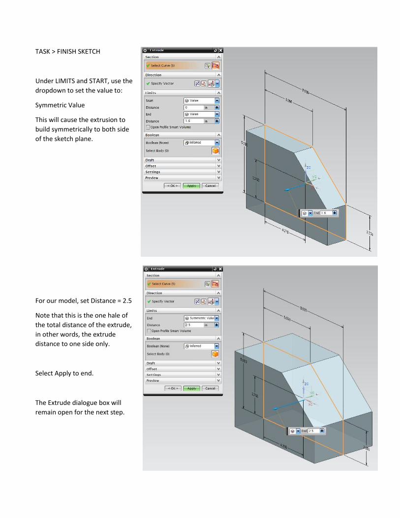
TASK > FINISH SKETCH
Under LIMITS and START, use the
dropdown to set the value to:
Symmetric Value
This will cause the extrusion to
build symmetrically to both side
of the sketch plane.
For our model, set Distance = 2.5
Note that this is the one hale of
the total distance of the extrude,
in other words, the extrude
distance to one side only.
Select Apply to end.
The Extrude dialogue box will
remain open for the next step.
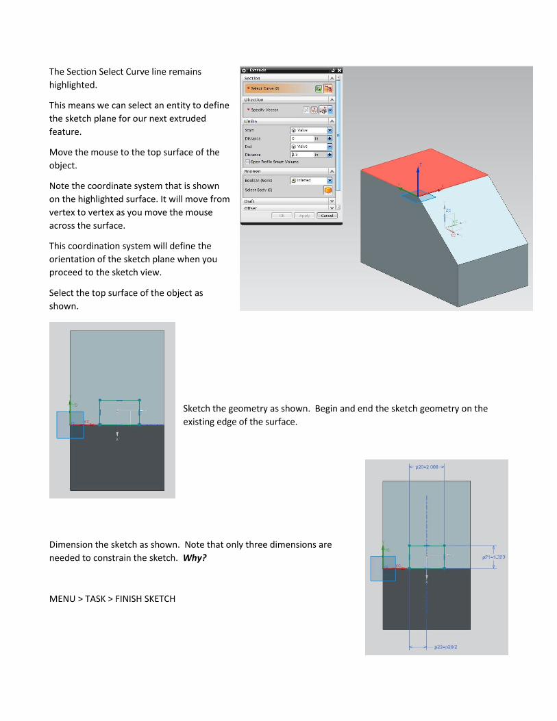
The Section Select Curve line remains
highlighted.
This means we can select an entity to define
the sketch plane for our next extruded
feature.
Move the mouse to the top surface of the
object.
Note the coordinate system that is shown
on the highlighted surface. It will move from
vertex to vertex as you move the mouse
across the surface.
This coordination system will define the
orientation of the sketch plane when you
proceed to the sketch view.
Select the top surface of the object as
shown.
Sketch the geometry as shown. Begin and end the sketch geometry on the
existing edge of the surface.
Dimension the sketch as shown. Note that only three dimensions are
needed to constrain the sketch. Why?
MENU > TASK > FINISH SKETCH
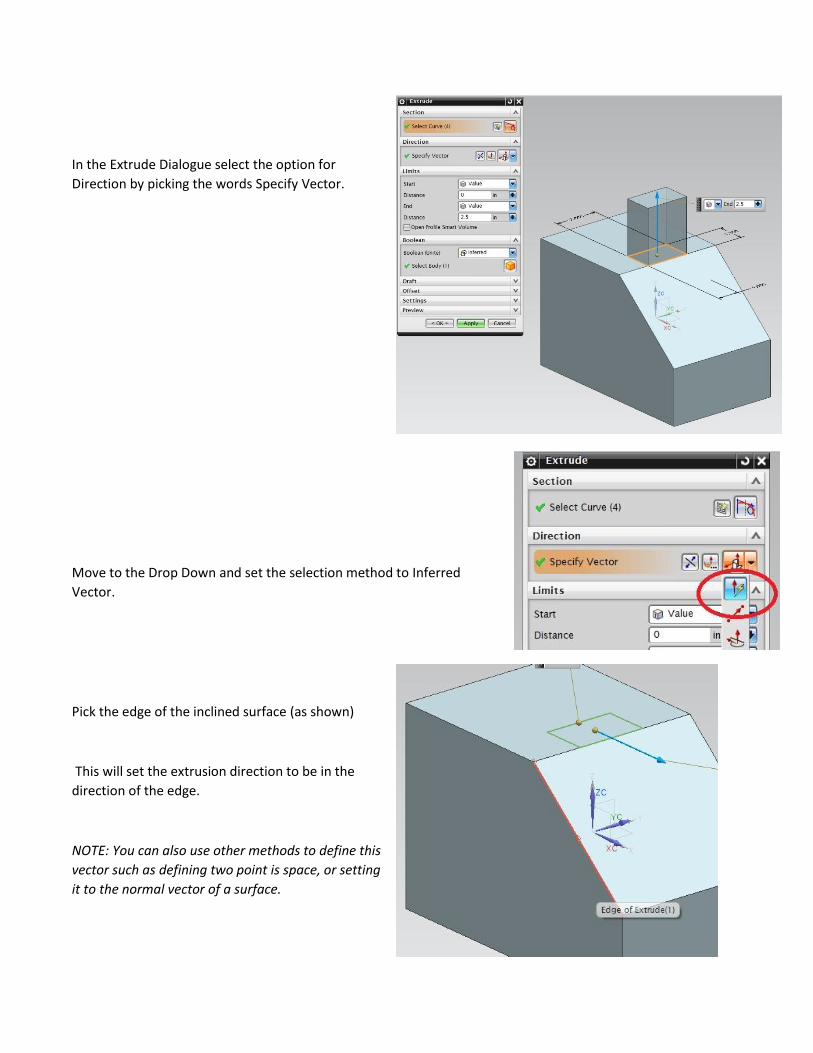
In the Extrude Dialogue select the option for
Direction by picking the words Specify Vector.
Move to the Drop Down and set the selection method to Inferred
Vector.
Pick the edge of the inclined surface (as shown)
This will set the extrusion direction to be in the
direction of the edge.
NOTE: You can also use other methods to define this
vector such as defining two point is space, or setting
it to the normal vector of a surface.
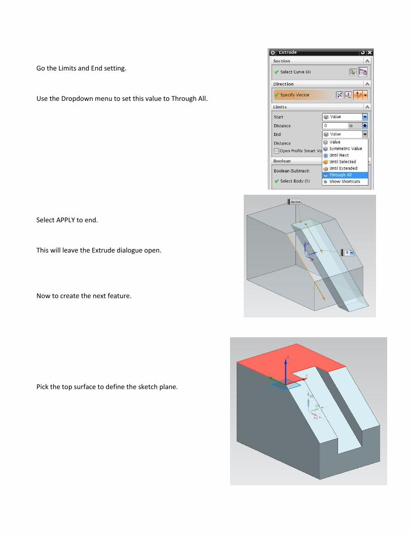
Go the Limits and End setting.
Use the Dropdown menu to set this value to Through All.
Select APPLY to end.
This will leave the Extrude dialogue open.
Now to create the next feature.
Pick the top surface to define the sketch plane.
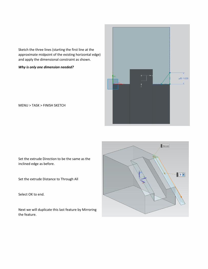
Sketch the three lines (starting the first line at the
approximate midpoint of the existing horizontal edge)
and apply the dimensional constraint as shown.
Why is only one dimension needed?
MENU > TASK > FINISH SKETCH
Set the extrude Direction to be the same as the
inclined edge as before.
Set the extrude Distance to Through All
Select OK to end.
Next we will duplicate this last feature by Mirroring
the feature.
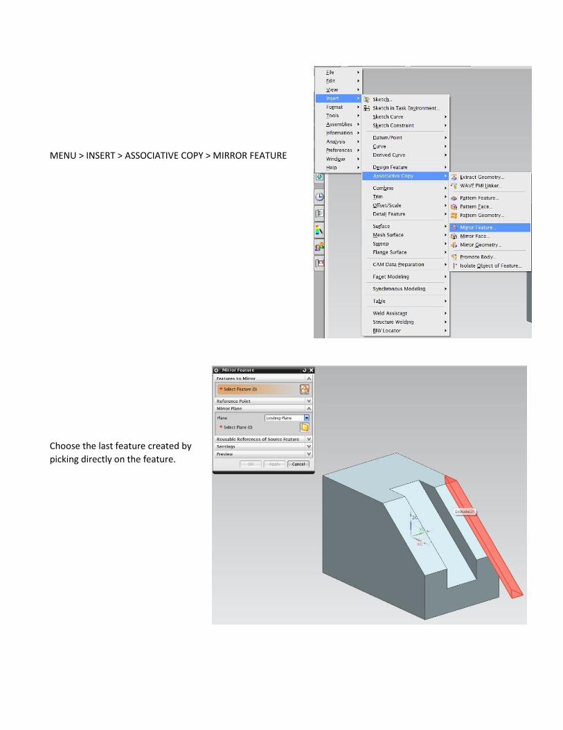
MENU > INSERT > ASSOCIATIVE COPY > MIRROR FEATURE
Choose the last feature created by
picking directly on the feature.
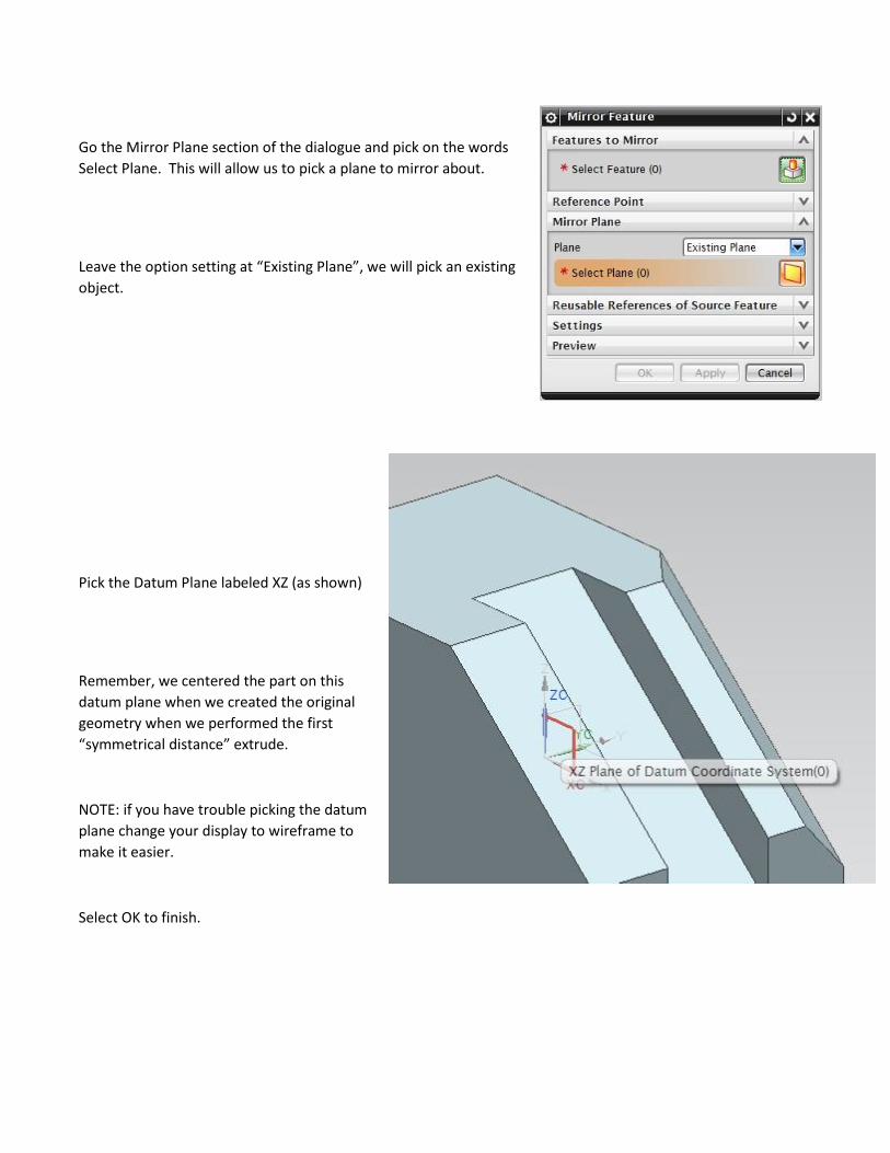
Go the Mirror Plane section of the dialogue and pick on the words
Select Plane. This will allow us to pick a plane to mirror about.
Leave the option setting at “Existing Plane”, we will pick an existing
object.
Pick the Datum Plane labeled XZ (as shown)
Remember, we centered the part on this
datum plane when we created the original
geometry when we performed the first
“symmetrical distance” extrude.
NOTE: if you have trouble picking the datum
plane change your display to wireframe to
make it easier.
Select OK to finish.


![Full page photoPMI NX Drafting PMI Convergent Drawing a-in Concept 'i]uviu NX Drafting tu 12 Point Curve tzí-nntu Drawing INX Security 12 Password Parts wag Assemblies tu Part Assembly](https://img.pdfslide.us/doc/110x75/5e62280804007012b872580e/full-page-photo-pmi-nx-drafting-pmi-convergent-drawing-a-in-concept-iuviu-nx-drafting.jpg)