Embed Size (px)
Citation preview

Acta Astronautica Wol. 19, No. 8, pp. 669~679, 1989 0094-5765/89 $3.00 + 0.00 Printed in Great Britain. All rights reserved Copyright © 1989 Pergamon Press plc
NUMERICAL SIMULATION OF VALVELESS PULSED COMBUSTORS
J. A. OLORUNMAIYE Department of Mechanical Engineering, University of Ilorin, Ilorin, Nigeria
and
J. A. C. KENTFIELD
Department of Mechanical Engineering, The University of Calgary, 2500 University Drive N.W., Calgary, Alberta, Canada T2N IN4
(Received 24 February 1988; revised version received 7 March 1989)
Abstract--The paper describes a mathematical model for simulating the cyclic operation of valveless pulsed combustors. The flows in the inlet and tail pipe were assumed to be one-dimensional while the combustion chamber was treated as a large reservoir with uniform thermodynamic properties. The effects of wall friction, heat transfer, gradual area changes, variable entropy and composition changes due to chemical reaction were included in the modelling. The set of first order quasi-linear hyperbolic partial differential equations describing the inlet and tail pipe flows were solved by a numerical method of characteristics. The results predicted with the model are in good agreement with some experimental results. The model showed that intermittent combustion in the combustion chamber is established through variations in the concentrations of carbon dioxide and oxygen. Lower and upper fuel flow rate extinction limits which have been observed experimentally, were found, from the results of the model, to be due to leanness and richness of the fresh charge in the combustion chamber, respectively.
I. INTRODUCTION
Increasing interest is currently being shown in the application of combustion-driven oscillation which was once usually considered a nuisance and sometimes a danger, in practical combustion systems. A pulsed combustor, by design, operates with combustion-driven oscillation which is induced by the use of special geometries. Intermittent combustion heat release at the pressure antinode while the pres- sure is within a small range of the maximum pressure (Rayleigh's criterion[l]) can result in high pressure amplitude in these combustors.
Domestic heating units in which these combustors are used are currently being marketed with the trade name LENNOX pulse furnace. Pulsed combustors have been used as propulsive devices for missiles[2]. Work is being done to develop this type'of combustor for gas turbine applications[3,4] because of their ability to operate with a gain in stagnation pressure as opposed to the inevitable pressure loss experienced in combustors being used in gas turbine plants at present.
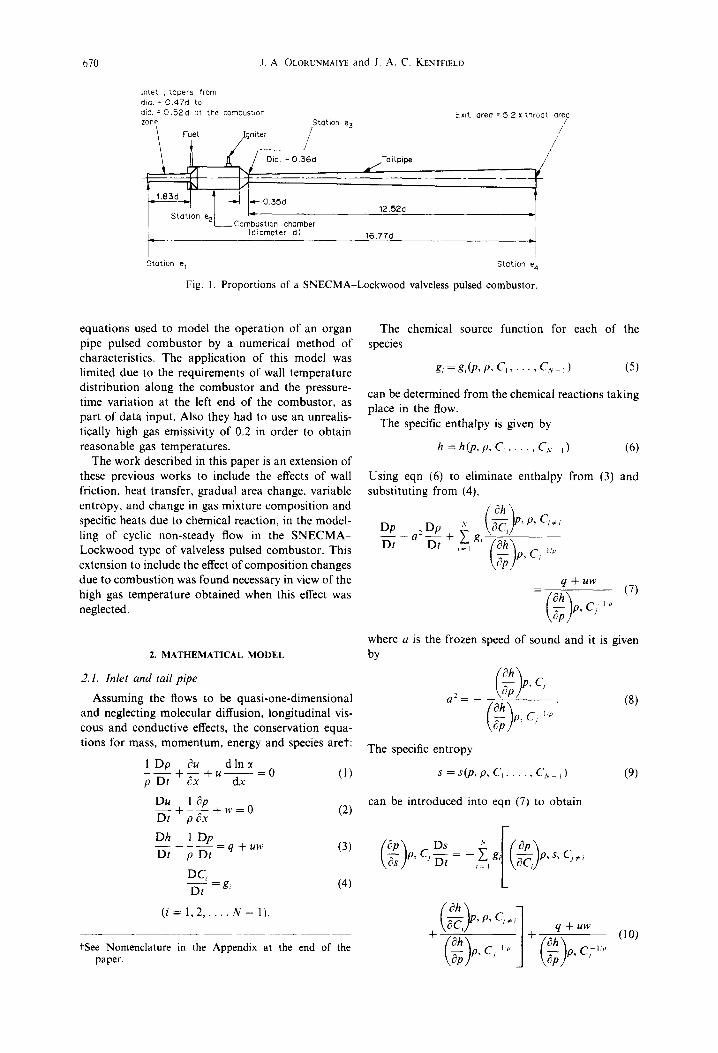
Pulsed combustors of many geometries have been built by many inventors. Whatever the shape of the geometry may be, a pulsed combustor has three major parts, namely: an inlet, a combustion chamber, and a tail pipe. The inlet may be equipped with valves or it may be valveless, the inlet, in that case, being designed to function as an aerodynamic valve. The geometry of the combustor used in this work, the SNECMA-Lockwood pulsed combustor is shown
in Fig. 1. The inner diameter of the combustion chamber is 73 mm.
Stations el, e2, e3 and e4 indicating, respectively, the open end of the inlet, the combustion-zone end of the inlet, the combustion-zone end of the tailpipe and the open end of the tailpipe are each identified in Fig. 1. The combustor has a maximum thermal loading of about 290 MW/m 3atm. (based on the combustion-zone volume only) which is more than ten times that of an aircraft gas turbine combustor.
A disadvantage of pulsed combustors which has slowed down their development is the difficulty of studying them theoretically due to the complexities of their working processes. This has resulted in a situ- ation whereby most advances have been made by experimental cut-and-try techniques since these combustors have simple geometries.
Marzouk[5] developed an isentropic cold flow model to simulate the cyclic operation of the SNECMA-Lockwood combustor. The combustion process was replaced by a simulated instantaneous injection of air resulting in a peak combustion cham- ber pressure corresponding to the pressure measured experimentally. The partial differential equations modelling flows in the inlet and tailpipe were solved by a numerical method of characteristics. Seifert[6] and Benson et al.[7] included friction, heat transfer, variable entropy and gradual area change in the calculation of unsteady one-dimensional flow in the exhaust pipe of an internal combustion engine. Clarke and Craigen[8] solved a similar set of
669
670 ,I. A OLORUNMAIYE and J. A. C. KENTF1ELD
InLet , tapers from dia. = 0.47d to dic. = 0.52d at the combushon zone Station e 3
/ FieL / g n i t e r /
Stat ion e2/ Combust I"l ion chamber
9 (diameter d) _
Station e 1
Exit area = 5 2 x throat ared / ,/
/ /
a t''/Ta i kpipe ~ I
12.52d
16.77d
i
Station e a
Fig. 1. Proportions of a SNECMA-Lockwood valveless pulsed combustor.
equations used to model the operation of an organ pipe pulsed combustor by a numerical method of characteristics. The application of this model was limited due to the requirements of wall temperature distribution along the combustor and the pressure- time variation at the left end of the combustor, as part of data input. Also they had to use an unrealis- tically high gas emissivity of 0.2 in order to obtain reasonable gas temperatures.
The work described in this paper is an extension of these previous works to include the effects of wall friction, heat transfer, gradual area change, variable entropy, and change in gas mixture composition and specific heats due to chemical reaction, in the model- ling of cyclic non-steady flow in the SNECMA- Lockwood type of valveless pulsed combustor. This extension to include the effect of composition changes due to combustion was found necessary in view of the high gas temperature obtained when this effect was neglected.
2. M A T H E M A T I C A L M O D E L
2.1. Inlet and tail pipe
Assuming the flows to be quasi-one-dimensional and neglecting molecular diffusion, longitudinal vis- cous and conductive effects, the conservation equa- tions for mass, momentum, energy and species aret:
1 Dp ?u d In :t p D---~ + ~ - + u - = O e x dx (l)
Du 1 ~p D~ + p ~x + w = 0 (2)
Dh 1 Dp Dt p Dt = q + uw (3)
DC, Dt = gg (4)
( i = 1 , 2 . . . . . N - I ) .
fSee Nomenclature in the Appendix at the end of the paper.
The chemical source function for each of the species
g, = gAP, P, C, . . . . . C,. ~) (5)
can be determined from the chemical reactions taking place in the flow.
The specific enthalpy is given by
h =h(p ,p ,C~ . . . . . CN_.~) (6)
Using eqn (6) to eliminate enthalpy from (3) and substituting from (4),
Dp : D p s ~ 'P, Ci,~
\ @ /
q + u w - ( 7 )
where a is the frozen speed of sound and it is given by
( O a , C ( 8 )
ep/ C71'°
The specific entropy
s = s ( p , p , Ci . . . . . C~. t) (9)
can be introduced into eqn (7) to obtain
P, P'C,N yg, S~ Cj~i
' q + u w (10)
j 7p

Valveless pulsed combustors 671
where another expression for the frozen speed of sound
c, . , ,
has been used.
2.2. Combustion chamber
The actual processes taking place in the combus- tion chamber are too complex to lend themselves to exact mathematical description and even if such a description can be made, the mathematical problem to be solved would probably be intractable. There- fore, it is assumed that the thermodynamic properties of the gas mixture in the combustion chamber are uniform and the mixture has homogeneous compo- sition and negligible kinetic energy. The last assump- tion is reasonable since the cross-sectional area of the combustion chamber is much larger than those of adjoining pipes. It is also assumed that change in potential energy of the combustion chamber content and molecular diffusion into or out of the combustion chamber are negligible.
The conservation equations are:
, , : ,
d V = Q - h + ~ p u . n d a (13)
f f f ~(pC~) f f f pg~ d V d V = - )3pCiu 'nd~t + --h--
(i = 1, 2 . . . . . N - i) (14)
where Q in eqn (13) is the rate of heat absorption in the combustion chamber due to convective and radia- tive heat transfer.
and the ratio of specific heats
y = Cp/Cv. (20)
The specific entropy of the mixture is
s = Cp In T/TR - R In P/PR N N
+lnl-IfTc'R'+ Z c, sr,. (21) i = l i ~ l
The relationship p =p(p,s), sometimes called the entropic equation of state, is
Es 1 (pRTR);' N = I-I f C,., ,'C,. (22) P pRlCv e x p -
i = 1
Equations (15), (17) and (22) can be used to derive the expressions for the partial derivatives in eqns (7), (8) and (10). Substituting for the partial derivatives and also for the substantial derivatives of density from (I) in eqn (7),
Dp : ~u d In ~ U fhip R . PyRi ~ D--~t + a p ~ + a2pu--~x + ~ _ l g i t - - ~ - + ~ - )
= (q + uw)pR/C~ (23)
where
h i = Cp,(T - TR) + hm (24)
Substituting for the partial derivatives in eqn (10),
Ds N F, fpTRR'~]fC~Cp,- CpC~'~ = - Cv ,Z g,.k,n t -)
'/i C v , ( s _ ~ C i s r , ) + ~ l n f c,. , . i
p Rh~ CC~, In f i f c,.,c.. + PC, I
i = l
(25)
2.3. Equations of state
The gas mixture is assumed to be thermally perfect
p = RpT (15)
where N
R = ~ C,R,. (16) i = l
Assuming the gas mixture to be calorically perfect,
h = Cr(T - TR) + ~ C, hr, (17)
The specific heats at constant pressure and tempera- ture are
N
Ct, = Z C, Cp, (18) i = l
N
C,. = Z C,C,., (19) i = l
2.4. Nondimensionalization of the equations
Choosing the length of the inlet 10, and the velocity of sound, the pressure, temperature and specific gas constant of the ambient air as the reference parame- ters, the nondimensional forms of eqns (2), (23), (25) and (4) are
c~P' c3P' c~U (9--Z + U--~ + ?oDA :
= -7oDA:F + E - B (26)
10P" ~U ~U Yg OX + - ~ + U ~ = - W (27)
DS = H + Y (28)
DZ
DC~ - - = G i (29) DZ
(i---- 1,2 . . . . . N - l )
672 J.A. OLORUNMAIYE and J. A. C. KENTFIELD
where
B - ,.[~7~v [C'p,(T'-T'R)+h;, ] -
E - ;'o(Q'+ UW)DR' c;
dln~ F = U - - d~
H= - C : ~ a, ff ln/DY"R"~{C;~ -~,'-~;-~,'C;] '=' [L \ P, /l\cv c , )
C: S - ,~,~" C'Sr' + E l n f
N C~,l n Hf~,,R,.(:~. DR'h;) < ,=,
Y = 7°R'D (Q' + UW). p
The results of the integrations in eqns (12)-(14) in the nondimensional forms are:
d mcc
dZ
dE~¢
dZ
dZ
D¢2~t'~ 2 U~2 - D~3ct'~, Ue, + J~/lf (30)
De2°t'~2 Ue2(h'~2 + ~ )
- D~c(~3 U~3(h'~3 + ~ Ue~)
+ ~IrC;~T ~ + M¢¢Q"
D¢z C~¢2ot'~ Ue2 - De3 C,o3~e3 Ue3
(31)
+ Gi~ M¢c
( i = 1,2 . . . . . N - I).
(32)
3. NUMERICAL METHOD
Equations (26)-(29) constitute a set of quasi-linear hyperbolic partial differential equations which can be solved using the method of characteristics. A numer- ical scheme, Hartree's hybrid scheme which was used by some earlier workers[7], is also used in this work. In this method, a rectangular grid is imposed on the integration domain and the equations are integrated along the characteristics directions. The dependent variables used are P' , U, S, C~, C, . . . . . Cu_ i.
Following the procedure given by Courant and Hilbert[9] the characteristic curves of eqns (26)-(29) can be shown to be
dX d-Z = U + A (33)
dX d-'-Z = U - A (34)
dX - - = U. (35) dZ
Equations (33) and (34) give the downstream and upstream propagation directions in the X-Z plane, of a pressure wave travelling at the frozen speed of sound relative to the fluid. Equation (35) represents N (the number of species) coincident characteristics which is the particle path line.
The compatibility equations along the charac- teristics of eqns (33) and (34), respectively, are
1 6+P" 6+U B - E 7oDA 6Z + ~ +AF+ W - - - = 0 (36) 7o DA
and
1 6 P " d_U AF E - B + - ~ - - + W + - - = 0 . (37) 7oDA 6Z YoDA The compatibility equations along the characteristic of eqn (35) are identically the same as eqns (28) and (29).
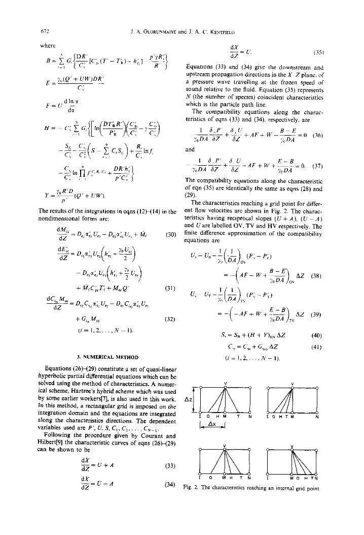
The characteristics reaching a grid point for differ- ent flow velocities are shown in Fig. 2. The charac- teristics having reciprocal slopes (U + A), ( U - A) and U are labelled OV, TV and HV respectively. The finite difference approximation of the compatibility equations are
1 Uv- U 0 - - -
70
Uv- U r - - -
(D-~ )ov(P~- P~)
- ( A F + W + ~ ) o v A Z (38)
1 ( l ) i ( P ~ - P ~ ) 70 D-A v
= - ( - A F + W + ~ ) T v A Z (39)
S, = SH + (H + Y)HV AZ (40)
C,~ = Ci. + G,.v AZ (41)
( i = 1 , 2 . . . . . N - l ) .
V V
I 0 H M T N I O H T M N
I_ zxx A
V V
I O M H T N I M O H TN
Fig, 2. The characteristics reaching an internal grid point,

Valveless pulsed combustors 613
For the Nth species,
N-l
c,+= 1 - c c,. I=1
(42)
The double subscripts on a term indicates that the term is taken to be the mean of its value at the end points indicated by the two subscripts (see Fig. 2).
The finite difference approximation of the combus- tion chamber equations given in eqns (30H32) are;
cc
>I : + A2
T” + AZ cc =
(43)
(44)
(45)
(46)
(47)
(48)
(49)
(50)
4. BOUNDARY CONDITIONS
The characteristics reaching the right end of the combustor which communicates with the ambient are shown in Fig. 3. The flow at the boundary is assumed to be quasi-steady. Rudinger[ lo] reported that results obtained from graphical method of characteristics analysis, assuming quasi-steady flow at the kind of boundaries encountered in this work, agreed well with experimental results.
4.1. Subsonic inflow
The inflow is assumed to be isentropic
S,=S,. (51)
a IJl I OM J ON
J IO HM J IO HT M
Fig. 3. The characteristics reaching the right boundary grid point.
The mass fractions of the species are the same as those of the species in the ambient air.
C,, = C, (i = 1,2,. . , N - 1). (52)
For the quasi-steady inflow, the energy equation can be expressed as
C’ T’ = C’P”‘-‘)P;T’ PA A P v R
s-t wfi
x pa’ -d/i exp i=l
c;
Equations (38) and (53) were solved by Newton’s method in 2-dimension to obtain p’ and U.
4.2. Sonic inflow
The velocity at the grid point equals the sonic velocity.
&=A,. (54)
But
A2 ,?&T’ (55) YO
and
T’ = p”1 - ‘/r,T;p$i?- lJexp
Substituting from eqns (54)--(56) in eqn (53)
(56)
(57)
674 J.A. OLORUNMAIYE and J. A. C. KENTFIELD
Supersonic inflow case is not considered since such a flow velocity is not attainable at an inlet plane in quasi-steady inflow unless a flow which is already supersonic is supplied to the intake.
4.3. Subsonic outflow For quasi-steady outflow, the static pressure at the
exit plane equals the ambient pressure
P~ = P~,. (58)
This equation and the compatibility equations along OV and HV are solved to obtain the values of dependent variables at the boundary.
4.4. Sonic/supersonic outflow
All the characteristics are washed downstream. Equations (38)-(42) are solved as for an internal grid point to obtain the values of dependent variables at the boundary.
4.5. Other boundaries
For the right end communicating with the combus- tion chamber, Pk, S~,, C~A in the equation above are replaced with the corresponding variables in the combustion chamber.
For the left end, the compatibility relations along characteristic OV are replaced with those of TV.
5. COMBUSTION MODEL
Complete oxidation of the fuel is assumed. Thus the products of combustion are CO: and H20, and it is necessary to take only 5 species into account: 02, N: , fuel, vapour and the products of combustion.
The following overall reaction equation which was used by Clarke and Craigen[8] is also used in this work.
rnf . . . . . _.~,~c3n,.~o: p t , - r L 5 r.o.5-2exp[_E/RuT]" (59)
In practice, complete oxidation does not occur and unburned hydrocarbons such as CO and NO, may be found in the exhaust gases. However, the use of overall kinetic approach is inevitable at this stage since with the present knowledge of chemical kinetics one cannot present a reliable detailed kinetic scheme for the reaction of propane with air in unsteady chemically-reacting flow as in a pulsed combustor.
The values of activation energy and reaction rate constant used are E = 30,000kJ/kmol and K = 4.5 x 10⁶ m3/kg s. These values are within the literature values of E and K which vary from 21,000 to 168,000 kJ/mol and 3.0 x 10⁶-4.8 × 10⁸ m3/kgs respectively[8].
6. HEAT TRANSFER AND WALL FRICTION
The rate o f heat transfer by convect ion and radia- tion from the wall to a grid node is
Ew+ 1 Q =he, ~i ,(Tw- T,)+----~aEg~,(T~.-- Tag). (60)
The frictional force per unit mass on the fluid element at the grid is
4Cf w = - d - ulu! tOl)
The friction factor Cf and the inner surface convec- tive heat transfer coefficient hc,~ were obtained using equations of the forms relating friction factor and Nusselt number to local flow parameters in steady flow as suggested by Bannister[11].
Cf = 0.25 Red ~.,5 (62)
hcmd/k = 0.023 Re °s Pr °33. (63)
7. INITIAL CONDITION
Since the flow in the pulsed combustor is a cyclic unsteady flow, a reasonable initial condition can be used to start the computation. The flow will auto- matically adjust itself to proper cyclic operation as the number of cycles increases, as a result of the effects of intermittent combustion and the boundary conditions. For the initial conditions, the combustor was assumed to be filled with air; the content of the combustion chamber being at pressure (P~, + 0.5) and temperature (TA+ 3.5) while the air in the inlet and tail pipe was assumed to be at ambient pressure and temperature.
Taking the tail pipe as a quarter wavelength tube and using acoustic theory, the nondimensional cycle period can be estimated using
4l a0 Zcyc[e ~ / ~ 10 (64)
where 7 ~--- estimated mean temperature in the tail pipe and l = tail pipe length.
From eqn (64), the minimum and the maximum time allowable for the cycle was determined. The cycle was allowed to terminate at some time between these extreme times if the difference between the mass inflow from the beginning of the cycle, into the combustion chamber and the mass outflow from it during the same time interval do not differ by more than 1%.
S. STABILITY CRITERION
The time step for a certain grid size was chosen in accordance with the Courant-Friedrichs-Lewy stability criterion[7] which requires that
AX AZ ~< A + I U ~ - - ] (65)
90% of the maximum allowable time step, according to this criterion, was used for the computations. When 110% of this time step was used, the computa- tion remained stable, showing that a little violation of this stability criterion is not critical. However, when 140% of this time step was used, instability was encountered in the computation.

Valveless pulsed combustors 675
Wove diagram plotted with mean velocities ~ Wove diagram plotted without mean velocities
[1. ° ~ i ~ . . . . . . Present numerical method E
Q,
° X , o 1
. \
I I I I I 0 1 2 3 4 5
Dimens ionLess t ime , Z
Fig. 4. Comparison of pressure at the closed left end of a shock tube predicted with the model with the results obtained by Rudinger using a graphical method of characteristics.
The stability criterion is, strictly speaking, valid for a linear system of equations. For nonlinear system of equations as in this work, it provides a useful guideline for choosing an appropriate time step[12].
More detailed description of the simulation of valveless pulsed combustors can be found else- where[13].
9. R E S U L T S A N D D I S C U S S I O N
The calculations were carried out on Control Data CYBER 175 computer. Details of the computer program can be found elsewhere[14].
To test the correctness of the formulation of the model, it was applied to predict the pressure at the left closed end of a uniform diameter shock tube initially filled with air (taken as a mixture of 76.7% nitrogen and 23.3% oxygen) at a nondimensional pressure of 2.83 and temperature of 1.346 discharging its content to the atmosphere through the right end which is fully
open. The result of the computation is compared, in Fig. 4, with that obtained by Rudinger[10] using a graphical method of characteristics. The agreement of the two results is quite good, remembering that the numerical method involves a lot of interpolations. Figure 5 shows the results predicted with the model using 41 and 501 grid points. The computation times were 31 and 4670 CPU s respectively. The improve- ment of the predicted result with increasing number of grid points is not commensurate with the increase in computation time. This illustrates the well known advantage of numerical method of characteristics-- that reasonable results can be obtained even with coarse grid size.
The results predicted for the operation of the valveless pulsed combustor for 16 cycles are shown in Table 1. The cyclic operation is well repeated by the 15th cycle. The results predicted in the 15th cycle with different grid sizes are shown in Table 2. The experi- mentally measured mean gas temperature of 5.33 in
3 E
\ a. o
O.
.=_o 1
i ~ ,/1 ~K)I Grid points 0 ~ 4t Grid points
I I I I J 0 1 2 3 4 5
D i m e n s i o n l e s s t i m e , Z
Fig. 5. Predicted pressure at the left end of the shock tube using 41 and 501 grid points in the computation.

676 J . A . OLORUNMAIYE a n d J. A. C. KENTFIELD
Table I. Computation results for 16 cycles using AX = 0.25* for a fuel flow rate of 7.24 kg/h
Mean dimensionless
Pm.~ in Pmi. in temperature in Cycle combustion combustion combustion
number chamber chamber chamber
I 1.500 0.801 3.84 2 2.240 0.761 4.88 3 2.227 0.786 5.18 4 2.126 0.790 5.41 5 2.073 0.785 5.44 6 2.073 0.783 5.35 7 2.102 0.783 5. I 1 8 2.166 0.774 5.17 9 2.236 0.777 5.17
10 2.228 0.775 5.21 11 2.221 0.776 5.23 12 2.220 0.777 5.22 13 2.226 0.776 5.22 14 2.230 0.776 5.23 15 2.230 0.776 5.23 16 2.229 0.776 5.23
Note: P0= 88.25 kPa (i.e. typical gary); T0= 289.0K
*Nondimensional lengths of the respectively.
local ambient conditions at Cal-
inlet and tail pipe are 1 and 6
1.0 ~\ ,t-
O.8 ~ / \ 0.6 ~ \
, ) \ 0.4 \ / \ , , " ~ _ S" _
. 0.2 ~ \ \ ~>/ /~" - " ~ > ~ 0 \\\ ///~,~ . . j / , /
-0.2 -0.4 \ / -0.6
8 -o.s ~, ~ e~ \ C: . . . . . . . . e~
- 1 . 0 ~ ,, e3
' i -1 .2 - I ,4 - I .6
- I .8
-2.O I l I i I I 0 2 4 6 8 10 12
D i m e n s i o n t e s s t i m e ) Z
Fig. 6. P red ic t ed velocit ies a t e , , e 2, e 3 a n d e 4 d u r i n g the cycle for a fuel f low ra te o f 7.24 kg /h .
the combustion chamber[13] is in good agreement with the results shown in Table 2.
It is expected that if the combustor is left to run from the discontinuous initial condition described in Section 7 without combustion-driven oscillation, the pulsation in the combustor will gradually die out with time. This was indeed observed when the program was run without combustion. The pressure range in the combustion-chamber reduced from Prom = 0.801 and Pm,x = 1.500 in first cycle to Pmi, = 0.940 and P~,x = 1.064 in the 15th cycle.
Figure 6 shows that the efflux from the tail pipe and the inlet lasts 59 and 40% of the cycle period respectively. This is in good argeement with Lock- wood's experimental work in which he reported 60 and 35% for the percentage efflux times for the tail pipe and inlet, respectively, for a somewhat similar U-shaped valveless pulsed combustor which he called type HC-1[15]. In the same work, Lockwood also observed that the efflux velocity from the inlet is much higher than that from the tail pipe, This also agrees well with the results shown in Fig. 6.
The model showed that the fresh air aspirated through the tail pipe end e 4 while the velocity there is negative only travels a maximum distance of
81mm, a small distance compared with 914mm length between e3 and e4. This shows that all the fresh air used for combustion in the combustion chamber is aspirated through the inlet.
The variation of mass fractions of the four species that paticipate in combustion process, in the combus- tion chamber, are shown in Fig. 7. It can be seen that the 02 mass fraction reduces rapidly during the combustion process (Z = 0.00-0.9) while CO2 concentration increases rapidly. Combustion is terminated in the combustion chamber due to short- age of oxygen, The 02 concentration remains low from Z = 1 to Z = 6.4 while the CO2 concentration remains high. Combustion cannot take place during this time interval even though the temperature of the gas mixture is high and the propane concentration builds up, since CO2 is known to narrow the air-fuel ratio flammable range[16]. After Z = 6.4, 02 concen- tration builds up while CO 2 mass fraction falls rapidly as more fresh air is inhaled through the inlet. It is duing this time that physical and chemical ignition delay occur. Intermittent combustion in the combution chamber is therefore established through variations in concentrations of carbon dioxide and oxygen.
Table 2. Results predicted in the 15th cycle using different grid sizes for a fuel flow rate of 7.24 kg/h
Mean dimensionless
Grid Pm,~ in Pmin in temperature CPU time size, combustion combustion in combustion required for AX* chamber chamber chamber 15 cycles (s)
0.500 2.181 0.785 4.80 41 0.250 2.230 0.776 5.23 206 0.100 2.334 0.779 5.28 992 0.500 2.350 0.781 5.48 3919 0.025t 2.419 0.781 5.t3 13414
*Nondimensional lengths of the inlet and tail pipe are 1 and 6 respectively. *Calculation was stopped at the end of the 13th cycle due to excessively high
computation time.

Valveless pulsed combustors 677
0 . 1 8
0,16
0.14
. . . . ~ 0 : :: o°0oo. \ oo.lo -o2 %
r . . . . . . . . . . . . /
; o.oo ' \\ / 0 . 0 6 / - .
o.o4 ~ I ,,"" / .......
o.o2~,'[ ..-"'" / / | ~ --t'- - - "--I- - - - - I " j I I I
0 2 4 6 8 10 12
D i m e n s i o n L e s s t i m e , Z
Fig. 7. Predicted mass fractions of species in the combus- tion chamber during the cycle for a fuel flow rate of
7.24 kg/h.
The average mass flow rate of gas t h rough e2 (mostly fresh air) and e3 (combus t ion products) into the combus t ion cham be r at different fuel flow rates are shown in Table 3. It can be seen tha t the rat io of average fuel flow rate to gas flow rate increases monoton ica l ly with fuel flow rate. In the experimen- tal unit, it was observed tha t there is a mass flow rate below which the combus to r will no t run and there is ano the r mass flow rate sett ing above which the combus to r fails to operate[13]. The model therefore suggests tha t these lower and upper ext inct ion limits are due to leanness and richness of the mixture in the combus t ion chamb e r respectively.
tO. SUMMARY
A numerical model for predict ing chemically react- ing flow in highly- loaded valveless pulsed combus to r s has been presented. It was found tha t reasonable gas tempera tures canno t be predicted in this type of pulsed combus to r wi thout consider ing the effect of
Table 3. Predicted air and combustion products aspiration rate into the combustion chamber at different fuel consumption rates
Gas flow rate from e: into Gas flow rate from
Fuel flow combustion % into combustion rate, chamber, chamber, mr
rh~ (kg/h) reel (kg/b) r/t~: (kg/h) m,: + m~
2.16 66.06 7.86 0.029 2.99 78.01 9.27 0.034 4•43 101.17 11.68 0•039 7•05 128.49 13.15 0•050 9.45 145.48 14.66 0•059
11.08 150.68 15.83 0•067 14.65 180.55 17.62 0.074
Note: (I) Stoichiometric fuel/air ratio of propane = 0.064. (2) Lower and upper flammability limits of propane in air for
upward flame propagation at atmospheric pressure and room tempcraturvll6] = 0.033, 0.161.
(3) Experimentally observed lower and upper extinction fuel flow rates in the pulsed combustor[131 = 2.00, 14.67 kg/h.
compos i t ion changes due to chemical react ion on the
specific heats. The results of the model showed tha t in te rmi t ten t
combus t ion in the combus t ion chamber is established th rough var ia t ions in the concent ra t ions of ca rbon dioxide and oxygen. It was also shown that fuel-a i r rat io varies with mass flow rate of fuel in this self-aspirating type of pulsed combustor . The results showed tha t the lower and upper fuel flow rate ext inct ion limits observed in the exper imental unit are due to leanness and richness of the mixture,
respectively. It was observed tha t all the fresh air used in the
combus t ion chamber comes f rom the inlet; the backflow in the tail pipe not being sufficiently s t rong to supply fresh air to the combus t ion chamber .
Acknowledgements--The leave of absence granted to first author by University of Ilorin, Nigeria, the financial assis- tance received by the second author from the Natural Sciences and Engineering Research Council of Canada, in the form of Operating Grant A7928, and the award of an haac Walton Killam Memorial Scholarship to the first author while this work was carried out, are acknowledged with appreciation•
REFERENCES
1. A. A. Putman, Combustion-driven Oscillations in Indus- try, pp. 2-3. Elsevier, New York (1971).
2. F. Gosslau, Development of the V-I pulse-jet. Agardo- graph No. 20, pp. 400-418. Appelhans, Brunswick (1957)•
3. J. A. C. Kentfield, M. Rehman and E. S. Marzouk, A simple pressure-gain combustor for gas turbines. J. Engng Power 99, 153-158 (1977).
4. J. A. C. Kentfield, A. Rehman and J. Cronje, Perfor- mance of pressure-gain combustors without moving parts. J. Energy 4, 56-63 (1980).
5. E. S. Marzouk, A theoretical and experimental inves- tigation of pulsed pressure-gain combustion. Ph.D. thesis, The University of Calgary (1974).
6. H. Seifert, A mathematical model for simulation of processes in an internal combustion engine. Acta Astro- nautica 6, 1361-1376 (1979).
7. R. S. Benson, R. D. Garg and D. Woollatt, A numerical solution of unsteady flow problems. Int. J. Mech. Sci. 6, 117-144 (1964).
8. P. H. Clarke and J. G. Craigen, Mathematical model of a pulsating combustor. Paper C54/76, Sixth Thermo- dynamics and Fluid Mechanics Convention, I. Mech. E. (1976).
9. R. Courant and D. Hilbert, Methods of Mathematical Physics, Vol. II, pp. 424-425. Interscience, New York (1962).
10. G. Rudinger, Nonsteady Duct Flow Wave-Diagram Analysis, pp. 186-193. Dover, New York (1969).
11. F. K. Bannister, Influence of pipe friction and heat transfer on pressure waves in gases: effects in a shock tube. J. Mech. Engng Sci, 6, 278-292 (1964).
12. J. F. T. Maclaren, A. B. Tramschek, A. Sanjines and O. F. Pastrana, A comparison of numerical solution of the unsteady flow equations applied to reciprocating compressor systems. J. Mech. Engng Sci. 17, 271-279 (1975)•
13. J. A. Olorunmaiye, Numerical simulation and experi- mental studies of highly-loaded valveless pulsed com- bustors. Ph.D. thesis, The University of Calgary (1985L

678 J .A. OLORUNMAIYE and J. A. C. KENTFIELD
14. J. A. Olorunmaiye, Computer programs for the numer- ical simulation of highly-loaded valveless pulsed com- bustors. Report No. 314, Department of Mechanical Engineering, The University of Calgary (1984).
15. R. M. Lockwood, Investigation of miniature valveless
pulse-jets, summary report. Report No. ARD-307, AD- 604-028, Hiller Aircraft Corp. (1964).
16. J. R. Cooper and J. W. Rose (Eds), Technical Data on Fuel, 7th edn, p. 247. The British National Committee World Energy Conference, London (1977).
APPENDIX
N o m e n c l a t u r e
Symbol Nondimensional form Meaning
Roman letters
a A = a /a o B , E , F , H , Y Ci Cc C~ C'p = cp / Ro Cp, Cp, = Cp,/R o C~ C'~ = C~IR o C~, C'~, = C,,~/R o d e e ' = e / R o T O E
Ec~ fcc/Po l g Ro To f , & Gi = & 1o/ao h h" = h / R o To H, M , O , T . h~ I, J, L, M, N , V K l0 m¢¢ M~: = m~¢/Po 13
1(4 = rh/pol~a o
N n
P P ' = P/Po q Q ' = qlo/a 3 Q
R R ' = R / R o
R i R: = & R o Ru s S = s /Ro t Z = tao/l o T T ' = T / T o
u U = u /a o v v ' = V/l~ w W = wlo/a2o x X = x/to
Greek letters
= cdc~ At A x E
p O"
Subscripts
A
C3 Hs el e2 e3 e4
~, = ~//0 ~
AZ AX
D = p/po
speed of sound groups of terms defined after eqn (29) mass fraction of the ith species friction factor specific heat of gas mixture at constant pressure specific heat of ith species at constant pressure specific heat of gas mixture at constant volume specific heat of ith species at constant volume duct diameter specific internal energy activation energy internal energy of combustion chamber content mole fraction of the ith species rate of production of the ith species per unit mass of the gas mixture enthalpy per unit mass feet of characteristics, (see Figs 2 and 3) convective heat transfer coefficient grid points (see Figs 2 and 3) reaction rate constant reference length mass of combustion chamber content mass flow rate mass of fuel consumed per unit volume in a unit time number of species unit vector normal to control surface at a point pressure heat transfer rate per unit mass heat transfer rate specific gas constant of gas mixture specific gas constant of ith species universal gas constant specific entropy time temperature velocity volume frictional force per unit mass axial distance
area ratio of specific heats time step size spatial grid size emissivity density Stefan-Boltzmann constant
ambient combustion chamber propane left end of the inlet right end of the inlet left end of the tail pipe right end of the tail pipe

Valveless pulsed combustors 679
Symbol Nondimensional form Meaning
f f,
g H ,O ,T HV in j
j # i max min 02 OV R
TV V W
0
Superscripts
Z z +Az
Operators
D
DZ
6+
6Z
6_
6Z
fuel internal energy, or enthalpy, or entropy of formation of the ith species per unit mass gas feet of characteristics (see Figs 2 and 3) along line HV (see Figs 2 and 3) inner wall surface all the species all the species except the ith species maximum minimum oxygen along line OV (see Figs 2 and 3) reference pressure or temperature for the definition of enthalpy, internal energy and change in entropy along line TV (see Figs 2 and 3) grid point V (see Figs 2 and 2) wall reference quantity; ambient air
normalized with respect to appropriate reference value time Z time Z + AZ
substantial derivative
differentiation following characteristic having reciprocal slope (U + A )
differentiation following characteristic having reciprocal slope (U - A )