Embed Size (px)
Citation preview

28
1. IntroductionNumerical methods based on finite element method
(FEM) are used in reinforced concrete modeling and considered as one of the best in behavioral studies, not only for structural engineering. In order to obtain a real course of analyzed phenomena, simulation must be based on material models describing the element under load. The behavior of reinforced
1. WprowadzenieMetody numeryczne bazujące na metodzie elemen-
tów skończonych (MES) używane są w modelowa-niu żelbetu i uważane za jedną z lepszych w badaniu zachowań konstrukcji nie tylko budowlanych. Aby symulacja odzwierciedlała rzeczywisty przebieg ana-lizowanych zjawisk, musi uwzględnić modele materia-łowe opisujące zachowanie pod działaniem obciążeń.
MICHAŁ SZCZECINA1
PAWEŁ TWORZEWSKIIZABELA UZARSKA
Kielce University of [email protected]
NUMERICAL MODELING OF REINFORCED CONCRETE BEAMS, INCLUDING THE REAL POSITION OF REINFORCING BARS
MODELOWANIE NUMERYCZNE BELEK ŻELBETOWYCH Z UWZGLĘDNIENIEM RZECZYWISTEGO ROZMIESZCZENIA
ZBROJENIADOI: 10.30540/sae-2018-003
Manuscript submitted 2017.08.22 - revised 2018.01.10, initially accepted for publication 2018.01.15, published in March 2018
A b s t r a c tThe article presents comparison of the results obtained from reinforced concrete beams experimental studies with the use of ARAMIS system (digital image correlation) with the results gained from numerical modeling. During studies, deviation from the plane of reinforced concrete beams was observed. Inventory of rebars positions in cross-section of this beams showed significant deviations. Analysis carried out in the work [1] revealed the impact of improperly embedded longitudinal reinforcement on the occurrence of horizontal displacements. Based on the collected data, numerical models of two selected reinforced concrete beams with correct and incorrect positon of the reinforcing bars were made using the Concrete Damaged Plasticity model in Abaqus software. It has been shown that premature interruption of the calculation appeared in models taking into account deviations in the position of reinforcing bars. However, the occurrence of horizontal displacements was still confirmed by numerical model for beams with incorrect positioning of rebars.
Keywords: beam, reinforced concrete, numerical modeling, executive errors, digital image correlation, ARAMIS system, Abaqus, concrete damaged plasticity
S t r e s z c z e n i eW artykule przedstawiono porównanie wyników badań eksperymentalnych belek żelbetowych z wykorzystaniem systemu ARAMIS (korelacja obrazu cyfrowego) z wynikami uzyskanymi w wyniku modelowania numerycznego. W wykonanych ba-daniach zaobserwowane zostało odchylenie z płaszczyzny belek żelbetowych, spowodowane niezgodnym z projektem roz-mieszczeniem prętów zbrojenia, co potwierdzono w pracy [1]. Inwentaryzacja położenia prętów zbrojeniowych w przekroju poprzecznym belek wykazała ich znaczne odchylenia. Na podstawie zebranych danych, w oprogramowaniu Abaqus, przy użyciu modelu Concrete Damaged Plasticity, wykonano numeryczne modele dwóch wybranych belek żelbetowych z prawi-dłowym oraz nieprawidłowym rozmieszczeniem prętów. Stwierdzono przedwczesne przerwanie obliczeń dla modeli uwzględ-niających odchylenie w położeniu prętów zbrojeniowych. Mimo to opracowany model numeryczny potwierdza występowanie przemieszczeń poziomych w belkach z niewłaściwym rozmieszczeniem prętów.
Słowa kluczowe: belka, żelbet, modelowanie numeryczne, błędy wykonawcze, digital image correlation, system ARA-MIS, Abaqus, concrete damaged plasticity

29
MODELOWANIE NUMERYCZNE BELEK ŻELBETOWYCH Z UWZGLĘDNIENIEM RZECZYWISTEGO ROZMIESZCZENIA ZBROJENIA
concrete as a composite material is random and the interpretation of phenomena still faces difficulties. Therefore, nonlinear numerical modeling that requires simplifying assumptions should be subjected to experimental verification. 26 reinforced concrete beams were tested in the Department of Strength of Materials and Concrete Structures laboratory of the Kielce University of Technology under the NR0400710 development project. During the studies, unusual behavior of beams was observed, namely large horizontal deflections. Those displacements were registered and measured with the use of optical measuring system ARAMIS (digital image correlation). For each element after its failure an inventory of reinforcement position in cross section was carried out (Fig. 3). Large deviations in rebars positioning in relation to project were discovered. Detailed analysis of the 14 selected elements [1] shows the huge influence of horizontal shift of the longitudinal reinforcement in the cross-section of the beams on the horizontal displacements and the development of cracks. In this article, using the data collected during the abovementioned studies, a comparison of the experimental results (of the two single-span beams) with the numerical modeling results (the degradation-plastic-brittle model) was presented.
2. Experimental StudiesTwo single-span beams with the same reinforcement
scheme (Fig. 1) were made in precast factory (concrete: C40/50; steel BS 500). As longitudinal reinforcement 3Ø12 and 2Ø14 bars in the bottom and 2Ø8 in the upper part were used (reinforcement ratio 2%). During the concreting, the following samples were taken: 150x150x150 cube shape samples and 150x300 mm cylindrical specimens. Fragments of reinforcement bars were also taken. Elements were supported with pot bearings (type of bridge bearing) and loaded monotonically with two concentrated forces until failure. The testing stand and static scheme were shown in Figure 2. The deviations in the position of the longitudinal reinforcement bars (Fig. 3) in the cross-section of the beams were not a targeted treatment. They resulted from errors made during the preparation of elements in the precast factory. Measurements of deformations on the lateral surface of the beams (the area under test is shown in Figure 2), spatial displacements and the width of the cracks were obtained with the use of ARAMIS system. Measurements of vertical displacement – beam deflection were verified using 5 inductive sensors.
Losowe zachowanie elementu żelbetowego złożonego z dwóch różnych materiałów powoduje, że interpre-tacja tych zjawisk nadal napotyka trudności. Dlatego szczególnie w obszarze nieliniowym, modelowanie numeryczne wymagające założeń upraszczających powinno być poddawane weryfikacji doświadczalnej. W laboratorium Politechniki Świętokrzyskiej WBIA KWMKBiM w ramach realizacji projektu rozwojo-wego NR0400710 wykonano badania 26 belek żelbe-towych. Podczas ich realizacji zaobserwowano niety-powe zachowanie się niektórych belek, tj. wychylenie się z płaszczyzny. Pomiary deformacji przestrzennych elementów wykonane za pomocą optycznego systemu pomiarowego ARAMIS zarejestrowały występowa-nie przemieszczeń poziomych elementów. Po zakoń-czonych badaniach wykonano inwentaryzację pozycji zbrojenia w przekroju (rys. 3). Odkryto duże odchyle-nia w pozycjonowaniu prętów zbrojeniowych w sto-sunku do projektu. Szczegółowa analiza 14 wybranych elementów [1] pokazuje wpływ przesunięcia poziome-go środka ciężkości zbrojenia podłużnego w przekro-ju belek na poziome przemieszczenia i powstawanie pęknięć. W tym artykule, wykorzystując dane zebrane podczas wyżej wymienionych badań, przedstawiono porównanie wyników eksperymentalnych dwóch be-lek jednoprzęsłowych z wynikami modelowania nu-merycznego (model degradacji plastyczno-kruchy).
2. Badania laboratoryjneDwie belki jednoprzęsłowe, o tym samym schema-
cie zbrojenia (rys. 1), wykonane zostały w zakładzie prefabrykacji z betonu o planowanej klasie C40/50 oraz stali BS500. W belkach jako zbrojenie podłużne zastosowano pręty 3Ø12 i 2Ø14 dołem oraz 2Ø8 górą (stopień zbrojenia 2%). Podczas betonowania belek pobierano próbki betonowe: kostki 150x150x150 oraz walce 150x300 mm. Pobrane zostały również odcinki prętów zbrojeniowych. Podczas badania belki pod-parte były na soczewkowych łożyskach mostowych i obciążane za pomocą dwóch sił skupionych w spo-sób monotoniczny do zniszczenia. Belkę na stanowi-sku oraz schemat statyczny badania przedstawiono na rysunku 2. Odchylenia w położeniu prętów zbrojenia podłużnego (rys. 3) w przekroju belek nie były zabie-giem celowym. Wynikały one z błędów popełnionych podczas wykonywania elementów w zakładzie prefa-brykacji. Odkształcenia na powierzchni bocznej belek (obszar poddany badaniu zaznaczony zakreśleniem na rysunku 2), przemieszczenia przestrzenne oraz sze-rokości rys mierzono systemem ARAMIS. Pomiary przemieszczeń pionowych – ugięcia belek – weryfi-kowano, wykorzystując pięć czujników indukcyjnych.

30
NUMERICAL MODELING OF REINFORCED CONCRETE BEAMS, INCLUDING THE REAL POSITION OF REINFORCING BARS
Fig. 1. Scheme of the reinforcement of the A2M1 and A2M2 beamRys. 1. Schemat zbrojenia belki A2M1 i A2M2
3. Optyczny system pomiarowy ARAMIS – Digital Image Correlation
ARAMIS jest bezdotykowym system pomiarowym, którego zasady działania oparte są na fotogrametrii ob-razowej [2], tzn. oprogramowanie w oparciu o zdjęcia odpowiednio przygotowanej powierzchni badanego elementu, rejestrowane za pomocą zestawu dwóch ka-mer, pozwala określić przemieszczenia przestrzenne, odkształcenia oraz wykonanie pomiaru szerokości rys. Uzyskiwana mapa odkształceń pozwala na śledzenie procesu rozwoju rys. Kumulacje odkształceń widocz-ne bardziej intensywnym kolorem na rysunkach 5, 8 i 9 odzwierciedlają miejsca powstawania rys. Podczas badań wykonywane są jedynie zdjęcia, dlatego też re-jestrację można prowadzić w sposób ciągły aż do mo-mentu zniszczenia elementu nie uszkadzając aparatury pomiarowej. Zastosowanie systemu w badaniach ele-mentów żelbetowych przedstawiono w pracach [1-4]. Podczas badań wykorzystano konfigurację systemu ARAMIS z jednym czujnikiem, w którym rozstaw pomiędzy kamerami wynosił 1200 mm. Konfiguracja systemu pozwala na jednoczesne zastosowanie dwóch czujników – 4 kamer. Analizie poddano powierzchnię środkową belek o szerokości 1200 mm i wysokości odpowiadającej wysokości belki, zgodnie ze schema-tem przedstawionym na rysunku 2.
Fig. 2. Testing stand with ARAMIS system and static scheme of elementsRys. 2. Stanowisko badawcze wraz z system optycznym ARAMIS i schemat statyczny belek
3. Optical Measuring System ARAMIS – Digital Image Correlation
ARAMIS is a non-contact measuring system which principles are based on image photogrammetry [2]. This mean that its software based on the analyses of surface images (digital image correlation) of the examined element, (recorded with a set of two cameras), allows to determine spatial displacements, strains and cracks width. Strain map on the examined element surface, allows to trace the development of the cracks (the accumulation of strains, which can be visible by more intense colors in Figures 5, 8 and 9, shows the place of formation of the crack). Because only images are taken during the test, the recording can also be carried out continuously until failure of element, without fear of damage to the measuring apparatus. The application of the system in the studies of reinforced concrete elements and others is presented in many publications [1-4]. In the presented studies, only one sensor with the 1200 mm distance between cameras was used. ARAMIS system configuration used in studies allows to use two sensors – 4 cameras in the same time. A 1200 mm wide area with a height equal to the height of the beam was analyzed (Fig. 2).

31
MODELOWANIE NUMERYCZNE BELEK ŻELBETOWYCH Z UWZGLĘDNIENIEM RZECZYWISTEGO ROZMIESZCZENIA ZBROJENIA
4. Numerical Model of Reinforced Concrete Beams – Parameters and Assumptions
The numerical analysis of the beams was performed with the use of finite element method implemented in Abaqus software [5]. The beam was modeled as a 3D object in spatial state of stresses and deformations. Reinforcement bars and concrete beams were divided into finite elements type C3D8R (8-node cubes). Finite element size was applied as 20 x 20 x 20 mm. Stirrups (vertical reinforcement) were defined as two-nodal B31 beam elements.
A2M1 A2M2
Concrete-steel co-operation was assured by the imposition of constraints such as "Embedded region" (reinforcing steel as "embedded" in a concrete element). This type of constraint assures the compatibility of the transitional degrees of freedom of embedded nodes of reinforcement with transitional degrees of freedom of the concrete host element (in this case – a concrete beam) [5]. The 3D view of the beam model with the coordinate system is shown in Figure 4. The s-e dependence for reinforcing steel was applied as elastic – ideally plastic. The mechanical and strength properties of the steel were determined according to the results of laboratory tests: Young's modulus E = 201.4 GPa, yield stress
Współpracę stali z betonem zapewniono przez narzu-cenie wymuszenia typu ,,Embeded region” (stal zbroje-niowa ,,osadzona” w elemencie betonowym). Ten typ wymuszenia polega na zapewnieniu zgodności prze-mieszczeń translacyjnych węzłów siatki MES zbrojenia z przemieszczeniami translacyjnymi siatki elementu be-tonowego (w tym przypadku belki betonowej) [5]. Wi-dok 3D zamodelowanej belki wraz z układem współ-rzędnych pokazano na rysunku 4. Zależność s-e dla stali zbrojeniowej zadano jako idealnie sprężysto-pla-styczną. Właściwości mechaniczne i wytrzymałościo-we stali przyjęto według wyników badań stali użytej w eksperymencie, mianowicie moduł Younga E = 201,4 GPa, granicę plastyczności fy = 558,5 MPa, maksymal-
Fig. 3. Stocktaking of the reinforcement for A2M1 and A2M2 beamRys. 3. Inwentaryzacja zbrojenia belek A2M1 i A2M2
Fig. 4. 3D presentation of the modeled beamRys. 4. Widok 3D zamodelowanej belki
4. Model numeryczny belek żelbetowych – parametry i założenia
Analizę numeryczną belek przeprowadzono meto-dą elementów skończonych, wykorzystując program Abaqus [5]. Belkę zamodelowano jako obiekt 3D w przestrzennym stanie naprężeń i odkształceń. Prę-ty zbrojeniowe oraz belkę betonową podzielono na elementy skończone typu C3D8R, czyli 8-węzłowe elementy sześcienne. Rozmiar elementu skończonego przyjęto równy 20 x 20 x 20 mm. Strzemiona zdefinio-wano jako dwuwęzłowe elementy belkowe typu B31.

32
NUMERICAL MODELING OF REINFORCED CONCRETE BEAMS, INCLUDING THE REAL POSITION OF REINFORCING BARS
fy = 558.5 MPa, maximum plastic deformation 0.04723. The Poisson's ratio was assumed as n = 0.3. The Concrete Damaged Plasticity [6, 7] model was used to model the behavior of concrete in Abaqus. Concrete parameters were assumed as following: Young's modulus E = 35 GPa, Poisson's ratio n = 0.167, dilation angle y = 30 degrees, eccentricity e = 0.1. The value of dilation angle was based on suggestion of Jankowiak [8], Genikomsou and Polak [9] and Szczecina and Winnicki [10, 11]. The ratio of maximum compressive stresses in biaxial to maximal stresses in uniaxial state was 1.16. In order to use the visco-plastic properties of concrete in the model, a viscosity coefficient (relaxation time) of 0.0001 s was input. The behavior of concrete under compression was given as the s-e dependence on the basis of the results of uniaxial compression tests conducted on cubic specimens. In Abaqus software, this relationship is given as a set of points on the s-e curve. The tensile behavior of the concrete was determined by the fracture energy Gf = 146.5 J/m2 for a yield stress 3.5 MPa. The fracture energy was calculated according to Model Code 2010 [12]. The assumption of fracture energy allowed to perform the “fracture energy trick” [13]. The beam load was applied as two concentrated forces which values depend on time. This dependency is given in the program based on the data from the experiment. The model also included dead weight of the beam and reinforcement (applied to the beam from the first step). Calculations were made in Abaqus using the Newton-Raphson method, assuming a minimum increment equal 10-6, and a maximum equal 10. The increment should be understood as the time given in seconds exactly as in the experiment. The end of the calculation was set in case of the lack of convergence or when the load reached the value of damage loading according to the results of the experiment. Calculations were carried out on three models: A2M1 and A2M2 beams, which contained the real reinforcement position (according to the inventories in the experiment) and the designed beam A2, in which the reinforcement was distributed symmetrically without deviations. The results are presented in the form of deformation, stress, nodal displacement, failure parameter under tension (DAMAGET) and compression (DAMAGEC), as well as equivalent tensile plastic strain (PEEQT).
ne odkształcenie plastyczne 0,04723, współczynnik Po-issona n = 0,3. Aby zamodelować zachowanie betonu użyto zaimplementowanego w Abaqus modelu Concre-te Damaged Plasticity (model plastyczny ze zniszcze-niem) [6, 7]. Przyjęto następujące parametry betonu: moduł Younga E = 35 GPa, współczynnik Poissona n = 0,167, kąt dylatancji y = 30 stopni, współczynnik ekscentryczności e = 0,1. Wartość kąta dylatacji przy-jęto na podstawie prac Jankowiaka [8], Genikomsou i Polak [9] oraz Szczeciny i Winnickiego [10, 11]. Sto-sunek maksymalnych naprężeń ściskających w sta-nie dwuosiowym do naprężeń maksymalnych w sta-nie jednoosiowym przyjęto równy 1,16. Aby włączyć w modelu własności wiskotyczne betonu, podano współczynnik lepkości (czas relaksacji) równy 0,0001 s. Zachowanie betonu, przy ściskaniu podano jako zależ-ność s-e na podstawie wyników badań laboratoryjnych przeprowadzonych na próbkach sześciennych podda-nych jednoosiowemu ściskaniu. W programie Abaqus zależność tę podaje się jako zbiór punktów na krzywej s-e. Zachowanie betonu przy rozciąganiu określo-no, podając energię kruchego pękania Gf = 146,5 J/m2 dla naprężenia powodującego zarysowanie równego 3,5 MPa. Energię kruchego pękania obliczono według zaleceń Model Code [12]. Założenie energii kruche-go pękania pozwoliło na użycie tzw. „fracture energy trick” [13]. Obciążenie belki stanowią dwie siły skupio-ne, których wartość zależna jest od czasu. Zależność tę podano w programie w oparciu o dane z eksperymen-tu. W modelu uwzględniono również obciążenie cię-żarem własnym belki i zbrojenia, który to ciężar jest przyłożony do belki od samego początku. Obliczenia zostały wykonane w Abaqus metodą Newtona-Ra-phsona przy sterowaniu obciążeniem, przy założeniu minimalnego przyrostu równego 10-6, a maksymal-nego 10. Przez przyrost należy rozumieć czas podany w sekundach, dokładnie tak samo jak w eksperymencie. Program kończy obliczenia albo przy braku zbieżności problemu nieliniowego, albo po osiągnięciu obciąże-nia równego wartości siły niszczącej według wyników eksperymentu. Obliczenia przeprowadzono dla trzech modeli: belek A2M1 oraz A2M2, które zawierały zbro-jenie przesunięte (zgodnie z inwentaryzacją przeprowa-dzoną w eksperymencie) oraz dla projektowanej belki A2, w której zbrojenie było rozłożone symetrycznie, bez przesunięć. Jako wyniki obliczeń odczytano: od-kształcenia, naprężenia, przemieszczenia węzłowe, parametr zniszczenia przy rozciąganiu (DAMAGET) oraz ściskaniu (DAMAGEC), a także obraz zarysowa-nia, odczytując ekwiwalentne odkształcenia plastyczne w rysie przy rozciąganiu (PEEQT).

33
MODELOWANIE NUMERYCZNE BELEK ŻELBETOWYCH Z UWZGLĘDNIENIEM RZECZYWISTEGO ROZMIESZCZENIA ZBROJENIA
5. Results of Calculations Obtained with the Use of ABAQUS Program and Their Comparison with the Experimental Results5.1. Results for Beam A2M1
Abaqus software has completed calculations for the beam A2M1 at the step for which the corresponding loading time is 7059 seconds (experiment time 11832 seconds). This means that the program did not found a convergence of the nonlinear problem for time t = 7059. Therefore, the crack pattern for the beam from the experiment and its numerical model were compared at the time mentioned earlier. The comparison of results is shown in Figure 5. For calculations made in Abaqus, cracks concentration is visible on one side of the beam at the location exactly under hydraulic jack No 3 (marked with arrow in Figure 5).
5. Rezultaty obliczeń przeprowadzonych w programie ABAQUS i ich porównanie z wynikami eksperymentalnymi5.1. Wyniki dla belki A2M1
Program Abaqus zakończył obliczenia dla belki A2M1 na kroku, dla którego odpowiadający czas ob-ciążania wynosi 7059 sekund (przy maksimum rów-nym 11832 sekund). Oznacza to, że program nie uzy-skał zbieżności zagadnienia nieliniowego dla czasu t = 7059. Dlatego też porównano obraz zarysowania dla belki z eksperymentu i dla jej modelu numeryczne-go dla tej właśnie chwili czasu. Obraz zarysowania dla belki modelowanej w Abaqus porównano z odpowia-dającym obrazem zarysowania belki z eksperymentu na rysunku 5. W przypadku obliczeń wykonanych w Abaqus zwraca uwagę fakt lokalizacji znaczne-go zarysowania po jednej ze stron (elewacji) belki w miejscu występującym dokładnie pod siłownikiem nr 3 (zaznaczono strzałką na rysunku 5).
Fig. 5. Strain map for the A2M1 beam from the test – Aramis system and equivalent tensile plastic strain (PEEQT) from the Abaqus softwareRys. 5. Mapa odkształceń dla belki A2M1 z eksperymentu – system ARAMIS i ekwiwalentne odkształcenia plastyczne przy rozciąganiu (PEEQT) uzyskane w programie Abaqus
In the case of laboratory tests, there are many places of propagation in the beam mainly under hydraulic jack No 2. Vertical displacement of point
W przypadku badań laboratoryjnych jest wiele miejsc propagacji rys w dolnym włóknie belki, głów-nie pod siłownikiem nr 2. Sporządzono również wy-

34
NUMERICAL MODELING OF REINFORCED CONCRETE BEAMS, INCLUDING THE REAL POSITION OF REINFORCING BARS
under hydraulic jack No 3 was also measured. The results are shown in Figure 6. The displacement gained in Abaqus at the end of the calculation is 10.13 mm, while deviation measured with ARAMIS system in the same time and place is 11.30 mm. Comparison of graphs indicates that the numerical model calculations were not completed due to beam failure (excessive cracks width, failure of concrete or excessive yielding of reinforcing steel) but due to lack of convergence of the nonlinear problem (despite the regularization using the visco-plastic properties of concrete). Nevertheless, the two paths are similar, and their similar slope indicates comparable stiffness of the beam both in the experiment and in Abaqus.
The maximum stress in steel according to the von Mises hypothesis reached 349.1 MPa. Taking into account the real yield point of this steel fy = 558.5 MPa, it was stated that the reinforcing steel in FEM model has not undergone any yielding in the cross section. This confirms the conclusion mentioned above that the program did not terminate calculations due to beam damage, but only due to lack of convergence. Nevertheless, the distribution of stresses in steel is characteristic for bending. The model also examined how far the beam moved from its plane (horizontal displacement) – in laboratory tests beam had relatively large displacements from the plane. For the last calculation step (t = 7059 s), the displacement from the plane in the center of the beam span reached approximately 2.4 mm (4.43 mm in experimental studies). We can conclude that torsion is smaller in the numerical model despite the fact that calculation was carried out in three-dimensional stress state and asymmetrical position of reinforcement was also input.
kres przemieszczenia pionowego węzła siatki MES zlokalizowanego w badaniach laboratoryjnych, tj. pod siłownikiem nr 3. Wyniki zestawiono na rysunku 6. Przemieszczenie z Abaqus w chwili zakończenia obliczeń to 10,13 mm, z doświadczenia – 11,30 mm. Porównanie wykresów wskazuje na to, że w modelu numerycznym w MES do przerwania obliczeń doszło nie w wyniku zniszczenia belki (nadmierne zaryso-wanie lub zmiażdżenie betonu albo nadmierne upla-stycznienie stali zbrojeniowej), ale na skutek braku zbieżności zagadnienia nieliniowego (pomimo zasto-sowanej regularyzacji w postaci włączenia własności wiskotycznych betonu). Niemniej jednak obydwie ścieżki są do siebie zbliżone, a ich podobne nachyle-nie świadczy o porównywalnej sztywności na zgina-nie dla belki z eksperymentu i z Abaqus.
Maksymalne naprężenie w stali wg hipotezy von Misesa osiągnęło wartość 349,1 MPa, co przy gra-nicy plastyczności tej stali fy = 558,5 MPa oznacza, że stal zbrojeniowa w modelu w Abaqus nie uległa uplastycznieniu w żadnym przekroju. Potwierdza to postawiony powyżej wniosek, że program nie przerwał obliczeń z powodu zniszczenia belki, a je-dynie z powodu braku zbieżności. Niemniej jednak rozkład naprężeń w stali jest charakterystyczny dla zginania. W modelu zbadano również, jak duże są przemieszczenia poziome belki, mając na uwadze, że w badaniach laboratoryjnych belka uległa stosun-kowo dużym przemieszczeniom z płaszczyzny. Dla ostatniego kroku obliczeń (t = 7059 s) przemiesz-czenie z płaszczyzny w środku rozpiętości belki wy-niosło około 2,4 mm, natomiast w doświadczeniu 4,43 mm. Można więc stwierdzić, że w modelu nu-merycznym brak jest wyraźnego skręcenia belki, po-mimo prowadzenia obliczeń w trójwymiarowym sta-nie naprężeń i niesymetrycznego ułożenia zbrojenia.
Fig. 6. Relation between the vertical displacement under the hydraulic jack no. 3 and time for the A2M1 beamRys. 6. Wykres zależności przemieszczenia pionowego od czasu pod siłownikiem nr 3 dla belki A2M1

35
MODELOWANIE NUMERYCZNE BELEK ŻELBETOWYCH Z UWZGLĘDNIENIEM RZECZYWISTEGO ROZMIESZCZENIA ZBROJENIA
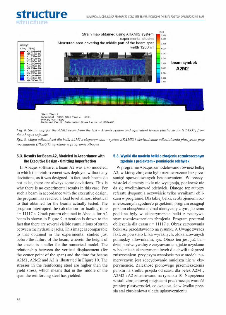
5.2. Results for Beam A2M2For this beam, Abaqus completed the calculation
in time t = 6694 s. This means that also in this case the program did not get the convergence of the nonlinear problem. A comparison of the results of the calculations and the results of the experimental studies was made for that time. The crack patterns obtained in the Abaqus and ARAMIS system are shown in Figure 8. The largest cracks obtained with both systems are located mainly under hydraulic jacks (dark red on the PEEQT strain map). The vertical displacement of the point under hydraulic jack No 3 is shown in Figure 7. The displacement calculated in Abaqus reached 10.07 mm, while value measured with ARAMIS system was 11.21 mm. The slope of both curves is similar, which again demonstrates comparable bending stiffness. For the last calculation step (t = 6694 s), the displacement from the plane in the center of the beam span was about 2.6 mm while during the real studies reached 3.83 mm for the same loading time. This partly confirms that the asymmetrical distribution of rebars in reinforced concrete beam cross-section affects on horizontal displacements of the beam but still differences in the obtained values are quite high.
5.2. Wyniki dla belki A2M2Dla tej belki program Abaqus zakończył obliczenia
dla czasu t = 6694 s. Oznacza to, że również w tym przypadku program nie uzyskał zbieżności zagadnie-nia nieliniowego. Porównano więc wyniki obliczeń z eksperymentem dla tej właśnie chwili czasu. Obraz zarysowania uzyskany w Abaqus oraz odpowiada-jące tej samej chwili czasu zarysowanie belki w eks-perymencie przedstawia rysunek 8. Podobnie jak dla belki A2M1 widać, że w Abaqus strefa zarysowana jest rozmyta w dolnych włóknach belki, przy czym w przypadku belki A2M2 widać już kilka różnych miejsc lokalizacji zarysowania (ciemny czerwony ko-lor na mapie odkształceń PEEQT). Przemieszczenia pionowe punktu pod siłownikiem nr 3 zestawiono na rysunku 7. Przemieszczenie w momencie przerwania obliczeń z Abaqus wynosiło 10,07 mm, natomiast z doświadczenia 11,21 mm. Ponownie widać, że ścież-ka dla modelu numerycznego kończy się przedwcze-śnie z powodu braku zbieżności. Nachylenie obydwu krzywych jest podobne, co także świadczy o porów-nywalnej sztywności belki na zginanie w obliczeniach komputerowych i w eksperymencie. Dla ostatniego kroku obliczeń (t = 6694 s) przemieszczenie z płasz-czyzny w środku rozpiętości belki wyniosło około 2,6 mm, a w eksperymencie 3,83 mm, tak więc podob-nie jak dla belki A2M1 obliczenia w programie Aba-qus częściowo potwierdzają wpływ niesymetrycznie rozmieszczonego zbrojenia podłużnego w przekroju belki na jej przemieszczenia poziome.
Fig. 7. Relation between the vertical displacement under the hydraulic jack no. 3 and time for the A2M2 beamRys. 7. Wykres zależności przemieszczenia pionowego od czasu pod siłownikiem nr 3 dla belki A2M2
36
NUMERICAL MODELING OF REINFORCED CONCRETE BEAMS, INCLUDING THE REAL POSITION OF REINFORCING BARS
Fig. 8. Strain map for the A2M2 beam from the test – Aramis system and equivalent tensile plastic strain (PEEQT) from the Abaqus softwareRys. 8. Mapa odkształceń dla belki A2M2 z eksperymentu – system ARAMIS i ekwiwalentne odkształcenia plastyczne przy rozciąganiu (PEEQT) uzyskane w programie Abaqus
5.3. Wyniki dla modelu belki o zbrojeniu rozmieszczonym zgodnie z projektem – pominięcie odchyłek
W programie Abaqus zamodelowano również belkę A2, w której zbrojenie było rozmieszczone bez prze-sunięć spowodowanych betonowaniem. W rzeczy-wistości elementy takie nie występują, ponieważ nie da się wyeliminować odchyłek. Dlatego też autorzy referatu dysponują oczywiście tylko wynikami obli-czeń w programie. Dla takiej belki, ze zbrojeniem roz-mieszczonym zgodnie z projektem, program osiągnął poziom obciążenia niemal identyczny z tym, jakiemu poddane były w eksperymencie belki z rzeczywi-stym rozmieszczeniem zbrojenia. Program przerwał obliczenia dla czasu t = 11117 s. Obraz zarysowania belki A2 przedstawiono na rysunku 9. Uwagę zwraca fakt, że powstało kilka wyraźnych, zlokalizowanych pomiędzy siłownikami, rys. Obraz ten jest już bar-dziej porównywalny z zarysowaniem, jakie uzyskano w badaniach eksperymentalnych dla chwili tuż przed zniszczeniem, przy czym wysokość rys w modelu nu-merycznym jest zdecydowanie mniejsza niż w eks-perymencie. Zależność pionowego przemieszczenia punktu na środku przęsła od czasu dla belek A2M1, A2M2 i A2 zilustrowano na rysunku 10. Naprężenia w stali zbrojeniowej miejscami przekraczają wartość granicy plastyczności, co oznacza, że w środku przę-sła stal zbrojeniowa uległa uplastycznieniu.
5.3. Results for Beam A2, Modeled in Accordance with the Executive Design - Omitting Imperfection
In Abaqus software, a beam A2 was also modeled, in which the reinforcement was deployed without any deviations, as it was designed. In fact, such beams do not exist, there are always some deviations. This is why there is no experimental results in this case. For such a beam in accordance with the executive design, the program has reached a load level almost identical to that obtained for the beams actually tested. The program interrupted the calculation for loading time t = 11117 s. Crack pattern obtained in Abaqus for A2 beam is shown in Figure 9. Attention is drawn to the fact that there are several visible cumulations of strain between the hydraulic jacks. This image is comparable to that obtained in the experimental studies just before the failure of the beam, wherein the height of the cracks is smaller for the numerical model. The relationship between the vertical displacement (for the center point of the span) and the time for beams A2M1, A2M2 and A2 is illustrated in Figure 10. The stresses in the reinforcing steel are higher than the yield stress, which means that in the middle of the span the reinforcing steel has yielded.

37
MODELOWANIE NUMERYCZNE BELEK ŻELBETOWYCH Z UWZGLĘDNIENIEM RZECZYWISTEGO ROZMIESZCZENIA ZBROJENIA
6. ConclusionsBased on the results obtained from numerical models
of the reinforced concrete beams and laboratory tests the following conclusions are drawn:• Numerical analysis of reinforced concrete beams,
reinforced in accordance with the executive design, using the Concrete Damaged Plasticity model and the 3D elements in the spatial state of stresses did not give fully satisfactory results. The interruption of the calculation appeared due to the lack of convergence of the nonlinear problem, not as a result of the exceeding of the bearing capacity of the element. Therefore, it is also not possible
6. WnioskiNa podstawie wyników uzyskanych z modelu nu-
merycznego oraz z badań laboratoryjnych belek żel-betowych stwierdzono, że:• Analiza numeryczna belek żelbetowych z uwzględ-
nieniem rzeczywistego rozmieszczenia prętów przy zastosowaniu modelu Concrete Damaged Plasticity oraz użycie elementu 3D w przestrzennym stanie naprężeń i odkształceń nie dała zadowalających wyników. Przerwanie obliczeń następuje z powodu braku zbieżności zagadnienia nieliniowego, a nie w wyniku wyczerpania nośności elementu, i nie ma możliwości dokładnej weryfikacji obliczeń z wyni-
Fig. 9. Strain map for the A2M1 and A2M2 beam from the test – Aramis system and equivalent tensile plastic strain (PEEQT) from the Abaqus software for A2Rys. 9. Mapa odkształceń dla belki A2M1 i A2M2 z eksperymentu – system ARAMIS i ekwiwalentne odkształcenia plastyczne przy rozciąganiu (PEEQT) uzyskane w programie Abaqus dla belki A2
Fig. 10. Relation between the vertical displacement under the hydraulic jack no. 3 and time for the A2M1, A2M2 and modeled beam A2Rys. 10. Wykres zależności przemieszczenia pionowego pod siłownikiem nr 3 dla belek A2M1, A2M2 eksperyment i zamodelowanej A2

38
NUMERICAL MODELING OF REINFORCED CONCRETE BEAMS, INCLUDING THE REAL POSITION OF REINFORCING BARS
to fully verify the calculation with experimental results (including horizontal displacement).
• Such convergence has been achieved for beam model without any deviations in position of rebars (A2). In this case vertical displacements and crack pattern were similar with the experimental results. But still it needs to be highlighted that this is not a real model.
• The impact of improperly embedded longitudinal reinforcement on the occurrence of horizontal displacements was partially confirmed (taking into account the limited number of results that could be compared due to lack of convergence in modeling). However, horizontal displacement values obtained in the numerical model were still slightly smaller.
kami doświadczalnymi, w tym również wychyleń z płaszczyzny dla pełnej ścieżki obciążania.
• Zbieżność osiągnięto jedynie dla belki nieuwzględ-niającej rzeczywistych odchyłek w położeniu prę-tów zbrojeniowych (A2). W przypadku tym prze-mieszczenia pionowe oraz obraz zarysowania były zbliżone do wyników eksperymentalnych. Należy jedna podkreślić, że model ten nie jest rzeczywisty.
• Analiza częściowo potwierdza wpływ nieprawidło-wo położonego zbrojenia podłużnego na przemiesz-czenia poziome elementów (biorą pod uwagę ogra-niczoną liczbę wyników, uzyskaną ze względu na brak zbieżności zagadnienia nieliniowego). Jednak-że wartości przemieszczeń poziomych dla modeli numerycznych belek były mniejsze niż rzeczywiste.
References [1] Tworzewski P., Ocena stanów granicznych zginanych elementów żelbetowych za pomocą optycznego system
pomiarowego, PhD thesis, Kielce 2016. [2] Tyson II J., Optical 3D Deformation and Strain Measurement, Pumps and Pipes, Proceedings of Annual Conference,
2011, pp. 147-164. [3] Tworzewski P., Goszczyńska B., An Application of an Optical Measuring System to Reinforced Concrete Beams
Analysis, 2016 Prognostics & System Health Management Conference – Chengdu (PHM-2016 Chengdu), China 2016.
[4] Goszczyńska B., Tworzewska J., Określenie rys na potrzeby analizy wyników badań procesu powstawania i rozwoju rys w belkach żelbetowych z zastosowaniem systemu ARAMIS. Przegląd Budowlany, 12 (2014), pp. 44-49.
[5] Abaqus/CAE ver. 6-12.2, User Manual, Dassault Systemes Simulia Corp., 2012. [6] Lubliner J., Oliver J., Oller J., Onate S., A plastic-damage model for concrete, International Journal of Solid Structures
No. 3 (1989), vol. 25, pp. 299-326. [7] Lee J., Fenves G.L., Plastic-Damage Model for Cyclic Loading of Concrete Structures, Journal of Engineering
Mechanics, vol. 124 (1998), pp. 892-900. [8] Jankowiak T., Kryteria zniszczenia betonu poddanego obciążeniom quasi-statycznym i dynamicznym, PhD thesis,
Poznań University of Technology, 2010. [9] Genikomsou A., Polak M.A., FEA of RC slabs under static and cyclic loadings based on damage plasticity model,
Proceedings of The 8th International Conference AMCM 2014 Wrocław.[10] Szczecina M., Winnicki A., Numerical simulations of corners in RC frames using Strut-and-Tie Method and
CDP model, Proceedings of The XIII International Conference on Computational Plasticity, Fundamentals and Applications, COMPLAS 2015, Barcelona 2015, pp. 608-619.
[11] Szczecina M., Winnicki A., Selected aspects of computer modeling of reinforced concrete structures, Archives of Civil Engineering 62 (2016), pp. 51-64.
[12] The FIB Model Code for Concrete Structures 2010.[13] Winnicki A., Szarliński J., Podleś K., Konstrukcje z betonu w płaskich stanach, Politechnika Krakowska, Kraków
2002.
Acknowledgments:This work was supported by Kielce University of Technology, Grant No. 02.0.06.00/2.01.01.02.0021 MNSC.BKWB.17.004
Podziękowania:Praca była finansowana przez Politechnikę Świętokrzyską, grant nr 02.0.06.00/2.01.01.02.0021 MNSC.BKWB.17.004