Embed Size (px)
Citation preview
Numerical and experimental transitionresults evaluation for a morphing wing
and aileron systemBotez, R, Koreanschi, A, Sugar-Gabor, O, Mebarki, Y, Mamou, M, Tondji, Y,Guezguez, M, Tchatchueng Kammegne, J, Grigorie, L, Sandu, D, Amoroso, F,
Pecora, R, Lecce, L, Amendola, G, Dimino, I and Concilio, A
http://dx.doi.org/10.1017/aer.2018.15
Title Numerical and experimental transition results evaluation for a morphing wing and aileron system
Authors Botez, R, Koreanschi, A, Sugar-Gabor, O, Mebarki, Y, Mamou, M, Tondji, Y, Guezguez, M, Tchatchueng Kammegne, J, Grigorie, L, Sandu, D, Amoroso, F, Pecora, R, Lecce, L, Amendola, G, Dimino, I and Concilio, A
Type Article
URL This version is available at: http://usir.salford.ac.uk/id/eprint/45185/
Published Date 2018
USIR is a digital collection of the research output of the University of Salford. Where copyright permits, full text material held in the repository is made freely available online and can be read, downloaded and copied for non-commercial private study or research purposes. Please check the manuscript for any further copyright restrictions.
For more information, including our policy and submission procedure, pleasecontact the Repository Team at: [email protected].
1
Numerical and Experimental Transition Results Evaluation
for a Morphing Wing and Aileron System
Ruxandra Mihaela Botez, Andreea Koreanschi, Oliviu Sugar Gabor
Research Laboratory in Active Control, Avionics and AeroServoElasticity
(LARCASE)
Ecole de Technologie Superieure, Montreal
Youssef Mebarki, Mahmoud Mamou
The Aerodynamics Laboratory, NRC Aerospace
Ottawa,
Canada
Yvan Tondji, Mohamed Guezguez, Joel Tchatchueng Kammegne, Lucian Teodor Grigorie, Dragos Sandu
Research Laboratory in Active Control, Avionics and AeroServoElasticity
(LARCASE)
Ecole de Technologie Superieure, Montreal
Francesco Amoroso, Rosario Pecora, Leonardo Lecce
University of Naples “Federico II”,
Industrial Engineering Dept. - Aerospace Division, Naples, Italy
Gianluca Amendola, Ignazio Dimino, Antonio Concilio
The Italian Aerospace Research Center
(CIRA)
Adaptive Structure Division, Capua (CE), Italy
Abstract
A new wing-tip concept with morphing upper surface and interchangeable conventional and morphing
ailerons was designed, manufactured, bench and wind tunnel tested. The development of this wing tip model
was performed in the frame of an international CRIAQ project, and the purpose was to demonstrate the wing
upper surface and aileron morphing capabilities in improving the wing tip aerodynamic performances.
During numerical optimization with ‘in-house’ genetic algorithm software, and during wind tunnel
experimental tests, it was demonstrated that the air flow laminarity over the wing skin was promoted, and the
laminar flow was extended with up to 9% of the chord. Drag coefficient reduction of up to 9% was obtained
when the morphing aileron was introduced.

2
Acronym List
Nomenclature List
CFD – Computational Fluid Dynamics
CIRA – Italian Center for Research in Aerospace
CRIAQ – Consortium for Research and Innovation in
Aerospace in Quebec
CRNC – Canadian National Research Council
ETS – Ecole de Technologie Superieure
MDO – Multi Disciplinary Objective
IR – Infrared thermography
UAV/UAS – unmanned aerial vehicle/system
λ - laminar to transition flow boundary parameter
Ci – case number i
Cd – drag coefficient
Cl – lift coefficient
Cp – pressure coefficient
Count – 1e-3
Ff – Fitness function
γ – Intermittency variable
τ – Transition to turbulent flow boundary parameter
Re – Reynolds number
Trerror – Absolute transition error
UpTr – Upper surface transition
Wi – fitness function weight
x/c – chord distribution
y+ - wall condition
I. Introduction
The air transportation industry is a key contributor to economic development around the world. Since the
beginning of civil aviation, there has been a steady increase in the number of passengers using airplanes as a fast and
safe transportation method, with airlines carrying almost three billion passengers worldwide in 2014 alone. This
achievement has also transformed the air transport industry into a non-negligible source of pollution. In 2014, over
2% of the worldwide carbon dioxide emissions were attributed to commercial airline companies 1.
Today, researchers compete to find the best solutions to be applied to solve the emission problem, both on long
and short terms. One such solution is the morphing of the aircraft. Aircraft morphing is not a new concept, as it was
applied by the military aviation on some of their more renowned aircrafts, such as the Grumann F-14 2, the North
American Aviation XB-70 Valkyrie prototype 3 and the AFTI/F-111 'Mission Adaptive Wing'
4. Recently, the
concept of aircraft morphing started being researched for civil and unmanned aviation as well.
A morphing wing could allow the aircraft to fly at optimal lift-to-drag ratios for any condition encountered
during flight by changing some of its wing characteristics. Researchers have proposed different technological
solutions for obtaining the desired wing adaptability, and some of the concepts have achieved important theoretical
performance improvements compared to the baseline design. However, the technology is still in the early stages of
development, its technological readiness level is still low, and only a few concepts have sufficiently progressed to
reach wind tunnel testing, and even fewer have actually been flight tested.
For the Unmanned Aerial Vehicles, research was conducted by many teams. Some of the most interesting morphing
applications were described by Sofla et al 5
and Barbarino et al 6 in their literature review papers. Interesting
research on the effect of morphing of the UAV and UAS wing related to their aerodynamic performances was
conducted by Sugar. O et al 7 and 8
.
Pecora et al.9 demonstrated the effectiveness of replacing the conventional segmented flap with a morphing
compliant high-lift device, in the case of a regional transport aircraft. Bilgen et al. 10 and 11
also presented the concept
of replacing the wing trailing-edge devices with a morphing surface, capable of achieving continuous camber
variations instead of rigid deflections. The morphing system was designed to replace the ailerons of an UAV, for
which it used rapid, electrical actuation mechanisms. Both wind tunnel experiments and preliminary flight test were
performed, and demonstrated the effectiveness of the concept at providing accurate roll control. Pankonien and
Inman 12
presented a concept for morphing ailerons designed to replace the conventional wing control surfaces of an
UAV. The aerodynamic performance of the system was evaluated using wing tunnel testing. The experimental
measurements focused on the drag coefficient penalties associated with classic control surface deflections at off-
design flight conditions. The use of the morphing trailing edge achieved drag reductions of up to 20% compared to
its original design, thus justifying its increased mass and complexity.
A project that was dedicated to developing a new concept of morphing wing for civil aviation was the CRIAQ
7.1 project 13, 14
. This project was developed under partnership between Bombardier Aerospace, Thales Avionics
3
Canada, Ecole de Technologie Superieure, Ecole Polytechnique and the Canadian National Research Council
(CNRC). The purpose of the project was the development of a wing model capable of deforming its upper surface
using controlled movement of two lines of shape memory alloy actuators installed on the upper surface skin 15 and 16
.
The morphing upper surface skin itself was developed through optimization techniques as Carbon-Kevlar
composite. The model’s capabilities were tested at the CNRC subsonic wind tunnel in Ottawa, and the objective of
the tests was to observe the behavior of the flow transition with the aim to delay it. The results have shown that the
wing model achieved high transition delays and the balance measurements have read drag coefficient reductions of
up to 20%17
. A subsequent aeroelastic study proved that the morphing technique would not induce flutter
phenomena during wind tunnel testing 18
. In addition, many breakthroughs were achieved in active open-loop 19
and
closed-loop 20
control using PID 21
, fuzzy logic and neural network controllers in wind tunnel testing 22 and 23
under
the auspices of this same project.
The research presented in this paper was conducted in the frame of the CRIAQ MDO 505 project
‘Morphing Architectures and Related Technologies for Wing Efficiency Improvement‘. This project was an
international collaboration between Canadian and Italian industry, academic and research teams. The Canadian
partners were Bombardier Aerospace, Thales Canada, Ecole de Technologie Superieure (ETS), Canadian National
Research Council (CNRC) and Ecole Politechnique. The Italian partners were Alenia Aermacchi, the University of
Naples Federico II (UNINA) and the Italian Center for Research in Aerospace (CIRA). The purpose of the project
was to develop a full-size wing tip structure equipped with a morphing upper surface and two types of ailerons: a
conventional rigid aileron and a morphing aileron. The objective of the development of such a wing-tip was
threefold: 1) through upper surface morphing and aileron morphing change the shape of the wing and influence its
aerodynamic performances towards delay of the transition of the flow between laminar and turbulent states; 2)
through optimization of the structure and of the upper surface composite skin, maintain a wing structure that
respects structural requirements for certification and remains similar to a real aircraft wing tip structure 24 and 25
; and
3) demonstrate that an integrated control system for the morphing upper surface and ailerons can achieve the desired
shapes obtained during numerical optimization 26 and 27
.
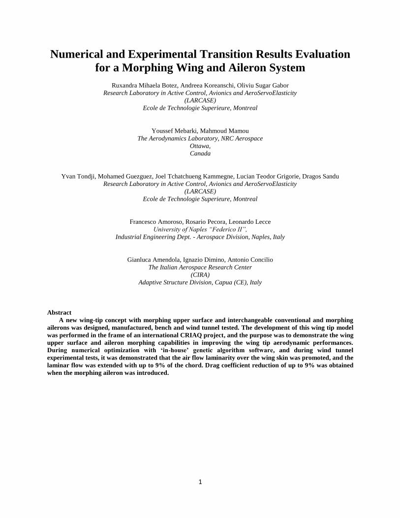
Figure 1 The layout of the morphing skin on the aircraft wing

4
Figure 2 The structural elements of the CRIAQ MDO 505 morphing wing box (the morphing skin is not shown in
the figure)
II. General Details on the Morphing Wing Model
The full-scale morphing wing model is a structure with a 1.5 m span and a 1.5 m root chord, a taper ratio of
0.72, and leading and trailing edges sweep angles of 8°. The chord distribution of the wing model follows the one of
the real wing-tip section, while the sweep angle and the spanwise twist distribution were modified (smaller twist and
sweep angle) in order to reduce the structure’s complexity and to obtain a more flat surface between the ribs to
better observe and measure the upper surface deformation. The wing box and its internal structure (spars, ribs, and
lower skin) were manufactured from aluminum alloy material, while the adaptive upper surface, which was
positioned between 20% and 65% of the wing chord, was manufactured using carbon fibre composite materials 28
.
The deformation of skin shape, driven by actuators placed inside the wing box structure, is a function of the
flight condition (defined in terms of Mach number, Reynolds number and angle of attack). These actuators were
specifically designed and manufactured to meet the project requirements. Four electrical actuators were installed on
two actuation lines; two actuators each, placed at 37% and 75% of the wing span, were fixed to the ribs and to the
composite skin. Each actuator has the ability to operate independently from the others, and has a displacement range
between ± 3.5 mm. On each actuation line, the actuators were positioned at 32% and 48% of the local wing chord.
The aileron hinge articulation was located at 72% of the chord. Two ailerons were designed and manufactured. One
aileron was structurally rigid, while the other one represented a new morphing aileron concept. Both ailerons were
designed to be attached to the same hinge axis of the wing box, and both are able to undergo a controlled deflection
between -7° and +7°. This interval was more restricted than the normal deflection range of an aileron, but it was
considered sufficient to demonstrate the proof of concept for the morphing aileron. This restriction was determined
by the available space inside the NRC wind tunnel and by the load limits of the wind tunnel balance. Figure 3
presents the morphing wing model concept as it would be mounted and tested in the NRC subsonic wind tunnel.

5
Figure 3 CRIAQ MDO 505 morphing wing model
The control of the actuators was realized with four various controllers – PID, Fuzzy Logic and two Neural
Network methods – that were integrated with the measurement systems incorporated into the model. Figure 4
presents an overview of the morphing wing control system.
The wing was equipped with 32 kulite pressure sensors installed on two parallel staggered lines at 60 cm
from the root of the wing. Three accelerometers were installed on the wing: one each on the wing box, aileron and
balance shaft, for safety purposes, by monitoring the vibration behaviour of the wing during wind tunnel tests.
The wing tip was manufactured at NRC and ETS, and complied with the technological requirements demanded
by the industrial partners.
EPOS2 24/5 drives
Hall sensors signal
CAN
Net
wor
k(C
ANop
en)
EtherNet(TCP/IP)EtherNet
(TCP/IP)
EtherNet(Modbus/TCP)
PWM
L 340 -LVDTs32 Kulite sensor
BLDC motors
CAN Network(CANopen)
Analog connections
Kollmorgen drive
BLDC motor (aileron actuator)
Figure 4 Overview of the morphing wing control system

6
2.1. Morphing Aileron
An important component of the wing tip, with high impact on its aerodynamic performances, was the aileron.
The conventional aileron, found on most aircraft wings, has a disadvantage that emboldened the research for a
concept to replace it. The disadvantage of the conventional aileron lies in the manner in which it changes the camber
of the wing. The aileron rotates around its hinge point, and thus creates a discontinuity of the slope of the airfoil
camber line that should be considered over the upper and lower surfaces. For high deflection angles, this
discontinuity can lead to premature boundary layer separation and a loss of efficiency for the aileron.
Therefore, the concept of a morphing aileron has been developed to replace the conventional rigid aileron, and thus
to avoid the problem of the discontinuity. In their paper, R. Pecora et al29
have demonstrated the potential of a
kinematic rib-based morphing structural system for a shape changing trailing edge device of a medium range
aircraft. I. Dimino et al30
have studied the safety and reliability aspects associated with the use of morphing trailing
edge device in a flying aircraft. Also, Barbarino and Pecora31
and Ameduri and Brindisi32
, have shown the
possibilities of using the SMA materials when developing shape changing devices by using an airfoil morphing
model and a morphing flap device equipped with SMA actuators. G. Diodati et al33
have analysed the performances
towards fuel consumption reduction of an adaptive trailing edge for a medium-size aircraft.
Figures 5 and 6 present the morphing aileron that was developed by the Italian partners. By preserving the
standard functionality as a conventional rigid aileron, morphing enabled an adaptive camber variation through a self-
contained kinematics driven by electromechanical actuators. The inner structure consisted of a segmented “finger-
like” architecture. Each rib was divided in three blocks connected by hinges and links, enabling relative rotation
among the components according to a specific gear ratio. In such a manner, the aerodynamic shapes spanned from a
target baseline to morphed configuration in the range of ±7 degrees through an un-shafted and distributed actuation
( G. Amendola et al 34
) .
Figure 5 Morphing aileron system

7
Figure 6 Morphing aileron internal structure
III. Shape Optimization and Aerodynamic Analysis
3.1. Aerodynamic optimization with Genetic Algorithm and Xfoil solver
During the wind tunnel tests, both the upper surface of the wing and the aileron shapes were actively morphed
based on the numerical optimization results. The deformation of the upper surface of the wing was driven by four
displacements points, resulted from the optimization process with Genetic Algorithm. Each set was calculated for a
flight condition (combination of speed, Reynolds number, angle of attack and aileron deflection). Each set of four
numerical displacements correspond to the set of four displacements of the electrical actuators installed in the wing
box. For the aileron morphing, the optimization has provided a guiding shape for each desired deflection, while
respecting constraints related to the constant thickness of the aileron, constant slope when aileron was morphing,
and established convention for measuring the aileron deflection angle.
It was assumed that the central region of the wing, between the two center ribs on which the actuators were
installed, would have a planar shape, thus the flow in this area would have bi-dimensional characteristics. Therefore,
the optimization was conducted on the wing’s airfoil.
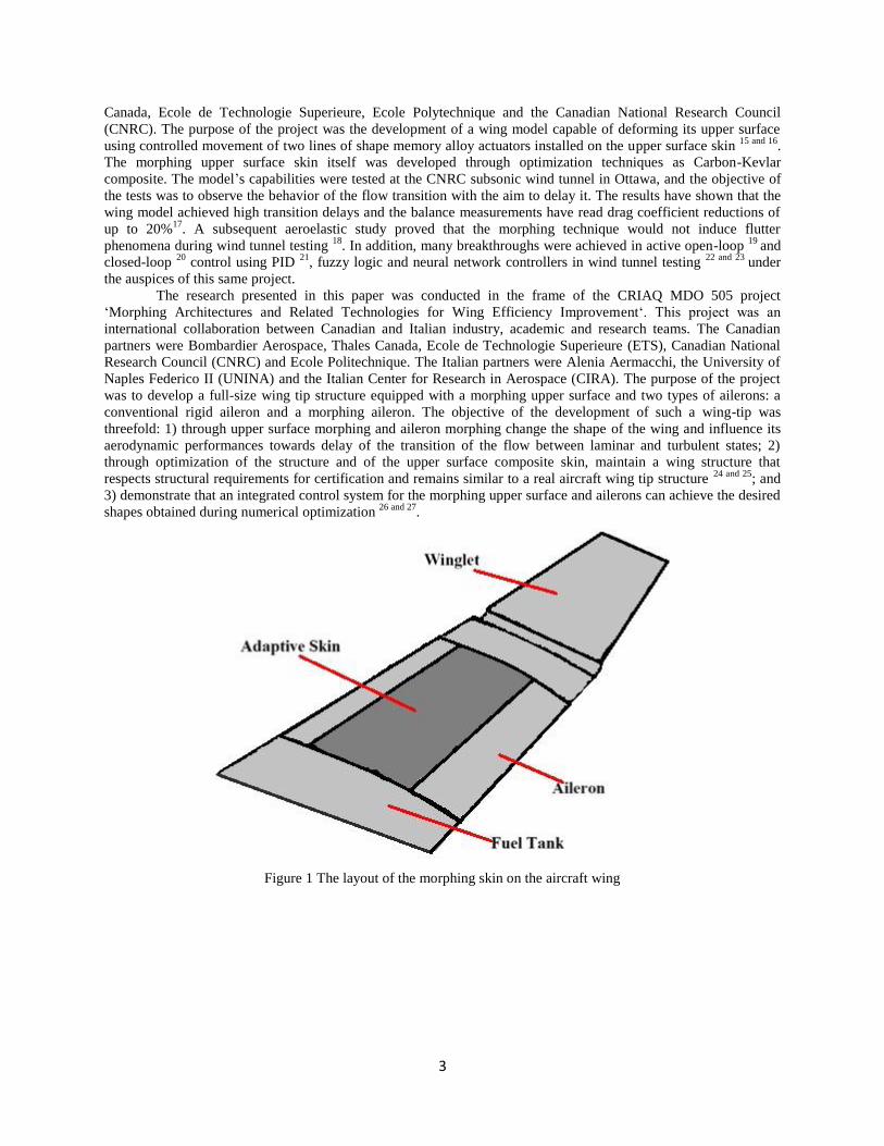
All the optimization, for both morphing upper surface and morphing aileron was performed with an ‘in-house’
developed genetic algorithm optimizer. The genetic algorithm optimizer was coupled with a cubic spline routine for
upper surface airfoil reconstruction, and with the XFoil aerodynamic solver for fast analysis of the optimization
candidates. General schematics of the optimization software applied to the morphing wing problem are presented in
Figure 7.
The genetic algorithm optimizer used a tournament process and a two-step cross-over function to speed up its
convergence. The optimal mutation parameters, the probability and the amplitude of mutation, were defined based
on percentages of the population and on the maximum displacements allowed. The optimizer was set to end the
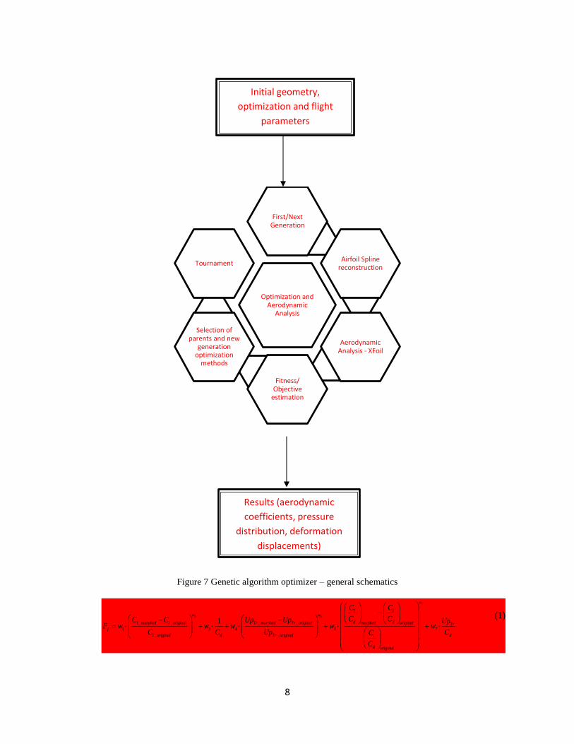
optimization after a total of 40 generations had passed. The fitness function, Ff, was based on multiple objective
functions developed from the aerodynamic parameters that were calculated by XFoil. The aerodynamic parameters
are: the lift and drag coefficients, pressure distribution, skin friction coefficient and upper surface transition location.
8
Figure 7 Genetic algorithm optimizer – general schematics
7
2 5
_ _ _ _
1 3 4 6 7
_ _
1
w
l lw w
d dl morphed l original Tr morphed Tr original morphed original Trf
l original d Tr original dl
d original
C C
C CC C Up Up UpF w w w w w
C C Up CC
C
(1)
Optimization and Aerodynamic
Analysis
First/Next Generation
Airfoil Spline reconstruction
Aerodynamic Analysis - XFoil
Fitness/ Objective
estimation
Selection of parents and new
generation optimization
methods
Tournament
Initial geometry,
optimization and flight
parameters
Results (aerodynamic
coefficients, pressure
distribution, deformation
displacements)

9
The results obtained by the optimization were the actuators’ displacements for the upper surface skin and
the morphed shapes for the morphing aileron.
The result obtained by the optimization algorithm were compared to the results obtained with two other
optimizers, the artificial bee colony and the gradient methods , which were validated with experimental results from
the CRIAQ MDO 505 wind tunnel test sessions and from other morphing wing projects 35 – 36
.
In Koreanschi et al37
, the genetic algorithm used for the optimization of the upper surface of the wing and for the
aileron morphing was described in detail, with full parameters choices, fitness function, cross-over, mutation,
convergence studies and comparisons with two other optimization methods – the ABC and the Gradient methods.
The optimization model was found to be robust and reliable and its results were validated using experimental data.
3.2. CFD aerodynamic analysis - Flow Equations, Turbulence and Transition Models
CFD simulations were performed to simulate the flow past the wing under the wind tunnel test flow conditions
and setup. The dynamics of fluid flow are governed by the Navier-Stokes equations, which are representative to the
fundamental principles of mass, momentum and energy conservation.
The numerical computations were performed with the ANSYS FLUENT solver38
. The steady-state flow
equations were solved using a projection method, achieving the constraint of mass conservation by solving the
pressure equation, with the pressure-velocity coupling accomplished by using a high-order Rhie-Chow scheme. The
cell-face values of the pressure were interpolated using a second-order central differencing scheme, while for all
other variables, including the turbulence and transition model equations, a second-order upwind scheme was used.
The discrete nonlinear equations were solved in a fully implicit, coupled manner. Convergence acceleration was
achieved with a coupled Algebraic Multi-Grid (AMG) approach, using a block-method Incomplete Lower-Upper
(ILU) factorization scheme as the linear system smoother.
For turbulent flows, the Reynolds Averaging Navier Stokes (RANS) technique is used to decompose the
instantaneous flow variables into their average values and turbulent fluctuations, while the Boussinesq eddy-
viscosity hypothesis is used to relate the Reynolds stress tensor and turbulent heat flux terms to the average flow
variables.
The turbulent viscosity and the kinetic energy are determined using the 𝑘 − 𝜔 Shear Stress Transport (SST)
model39
. The SST model represents a combination of the 𝑘 − 𝜔 model, used in the near wall region, and the 𝑘 − 𝜀
model, used for the rest of the flow. Thus, it achieves both accurate boundary layer representation up to the viscous
sub-layer, and insensitivity to boundary conditions at free-stream flow.
In order to include the effects of laminar flow, and to model the laminar-to-turbulent transition process, the
𝛾 − 𝑅𝑒𝜃𝑡 model is used36
.
The transition onset is controlled by an empirical correlation between 𝑅𝑒𝜃𝑐, the critical Reynolds number
where the intermittency starts to increase in the boundary layer and 𝑅𝑒𝜃𝑡̅̅ ̅̅ ̅̅ 40
. The model contains correction terms to
account for laminar separation-induced transition and strong pressure-gradient flows. Coupling of the 𝛾 − 𝑅𝑒𝜃𝑡
transition model with the 𝑘 − 𝜔 SST turbulence model is done by modifying 𝑃𝑘 and 𝐷𝑘 , which are the turbulent
kinetic energy production and the destruction terms, and thus deactivating the turbulence model for the laminar
boundary layer region.
3.3. Grid Convergence Study
The structured meshes used for the numerical simulation were generated using the ICEM-CFD software. A grid
convergence study was performed in order to evaluate the mesh density required to obtain grid-independent
aerodynamic coefficients values. Four meshes of increasing cell density were generated, and each one was analysed
at a Mach number of 0.15, a Reynolds number of 4.53E+06 (calculated with the wing mean aerodynamic chord) and
an angle of attack of 0°. The details regarding the wall cell density for the generated meshes are presented in Table
1.
10
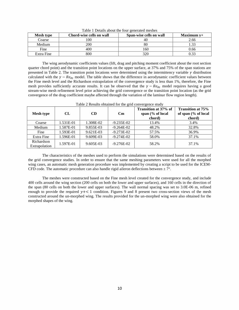
Table 1 Details about the four generated meshes
Mesh type Chord-wise cells on wall Span-wise cells on wall Maximum y+
Coarse 100 40 2.66
Medium 200 80 1.33
Fine 400 160 0.66
Extra Fine 800 320 0.33
The wing aerodynamic coefficients values (lift, drag and pitching moment coefficient about the root section
quarter chord point) and the transition point locations on the upper surface, at 37% and 75% of the span stations are
presented in Table 2. The transition point locations were determined using the intermittency variable 𝛾 distribution
calculated with the 𝛾 − 𝑅𝑒𝜃𝑡 model. The table shows that the difference in aerodynamic coefficient values between
the Fine mesh level and the Richardson extrapolation of the convergence study is less than 1%, therefore, the Fine
mesh provides sufficiently accurate results. It can be observed that the 𝛾 − 𝑅𝑒𝜃𝑡 model requires having a good
stream-wise mesh refinement level prior achieving the grid convergence or the transition point location (as the grid
convergence of the drag coefficient maybe affected through the variation of the laminar flow region length).
Table 2 Results obtained for the grid convergence study
Mesh type CL CD Cm
Transition at 37% of
span (% of local
chord)
Transition at 75%
of span (% of local
chord)
Coarse 1.531E-01 1.308E-02 -9.235E-02 13.4% 3.4%
Medium 1.587E-01 9.855E-03 -9.264E-02 48.2% 32.8%
Fine 1.593E-01 9.621E-03 -9.273E-02 57.5% 36.9%
Extra Fine 1.596E-01 9.609E-03 -9.274E-02 58.0% 37.1%
Richardson
Extrapolation 1.597E-01 9.605E-03 -9.276E-02 58.2% 37.1%
The characteristics of the meshes used to perform the simulations were determined based on the results of
the grid convergence studies. In order to ensure that the same meshing parameters were used for all the morphed
wing cases, an automatic mesh generation procedure was implemented by creating a script to be used for the ICEM-
CFD code. The automatic procedure can also handle rigid aileron deflections between ± 7°.
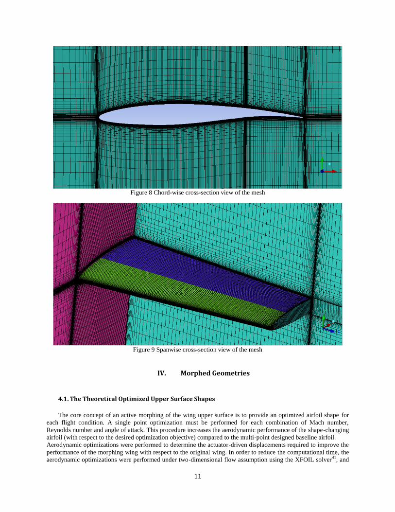
The meshes were constructed based on the Fine mesh level created for the convergence study, and include
400 cells around the wing section (200 cells on both the lower and upper surfaces), and 160 cells in the direction of
the span (80 cells on both the lower and upper surfaces). The wall normal spacing was set to 3.0E-06 m, refined
enough to provide the required 𝑦+< 1 condition. Figures 9 and 8 present two cross-section views of the mesh
constructed around the un-morphed wing. The results provided for the un-morphed wing were also obtained for the
morphed shapes of the wing.
11
Figure 8 Chord-wise cross-section view of the mesh
Figure 9 Spanwise cross-section view of the mesh
IV. Morphed Geometries
4.1. The Theoretical Optimized Upper Surface Shapes
The core concept of an active morphing of the wing upper surface is to provide an optimized airfoil shape for
each flight condition. A single point optimization must be performed for each combination of Mach number,
Reynolds number and angle of attack. This procedure increases the aerodynamic performance of the shape-changing
airfoil (with respect to the desired optimization objective) compared to the multi-point designed baseline airfoil.
Aerodynamic optimizations were performed to determine the actuator-driven displacements required to improve the
performance of the morphing wing with respect to the original wing. In order to reduce the computational time, the
aerodynamic optimizations were performed under two-dimensional flow assumption using the XFOIL solver41
, and
12
an in-house genetic algorithm optimizer, for local flow conditions (local Reynolds number and angle of attack)
calculated for the mean aerodynamic chord of the wing model42
.
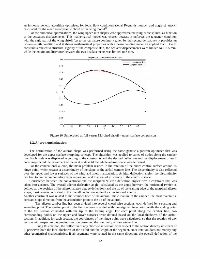
For the numerical optimizations, the wing upper skin shapes were approximated using cubic splines, as function
of the actuators displacements. This mathematical model was chosen because it enforces the tangency condition
with the rigid part of the wing airfoil (up to the curvature continuity given by the second derivative), it provides an
iso-arc-length condition and it shares mathematical properties with a beam bending under an applied load. Due to
constraints related to structural rigidity of the composite skin, the actuator displacements were limited to ± 3.5 mm,
while the maximum difference between the two displacements was limited to 6 mm.
Figure 10 Unmorphed airfoil versus Morphed airfoil – upper surface comparison
4.2. Aileron optimization
The optimization of the aileron shape was performed using the same genetic algorithm optimizer that was
developed for the upper surface morphing concept. The algorithm was applied to series of nodes along the camber
line. Each node was displaced according to the constraints and the desired deflection and the displacement of each
node engendered the movement of the next node until the whole aileron shape was deformed.
For the conventional aileron, the main problem resided in the rotation of the entire control surface around its
hinge point, which creates a discontinuity of the slope of the airfoil camber line. The discontinuity is also reflected
over the upper and lower surfaces of the wing and aileron articulation. At high deflection angles, the discontinuity
can lead to premature boundary layer separation, and to a loss of efficiency of the control surface.
Consistence between the conventional and the morphed ‘aileron deflection angles’ was a constraint that was
taken into account. The overall aileron deflection angle, calculated as the angle between the horizontal (which is
defined as the position of the aileron at zero degree deflection) and the tip of the trailing edge of the morphed aileron
shape, must remain consistent to the overall deflection angle of a conventional aileron.
Another constraint was related to the ‘camber line’ of the aileron. The curvature of the camber line must maintain a
constant slope direction from the articulation point to the tip of the aileron.
The aileron camber line has been divided into several chord-wise sections; each defined by a starting and
an ending point. The starting point of the first section coincided with the original hinge point, while the ending point
of the last section coincided with the tip of the trailing edge. For each point along the camber line, two
corresponding points on the upper and lower surfaces were defined based on the local thickness of the airfoil
section. In addition, for each section, the coordinates of the hinge point were calculated, so that the rotation of any
section with respect to the previous section preserved the continuity of the camber line.
Using this method, the deflection of any chord-wise section, with respect to the section directly upstream of
it, preserves both the local thickness of the airfoil and the length of the segment, since rotation does not modify any
other geometrical characteristics. If all segments were rotated in the same direction, the overall deflection of the
13
aileron, as measured at the trailing edge and using the original hinge point as reference, was simply the sum of all
segments rotations, where each segment was rotated with reference to the segment immediately upstream of it.
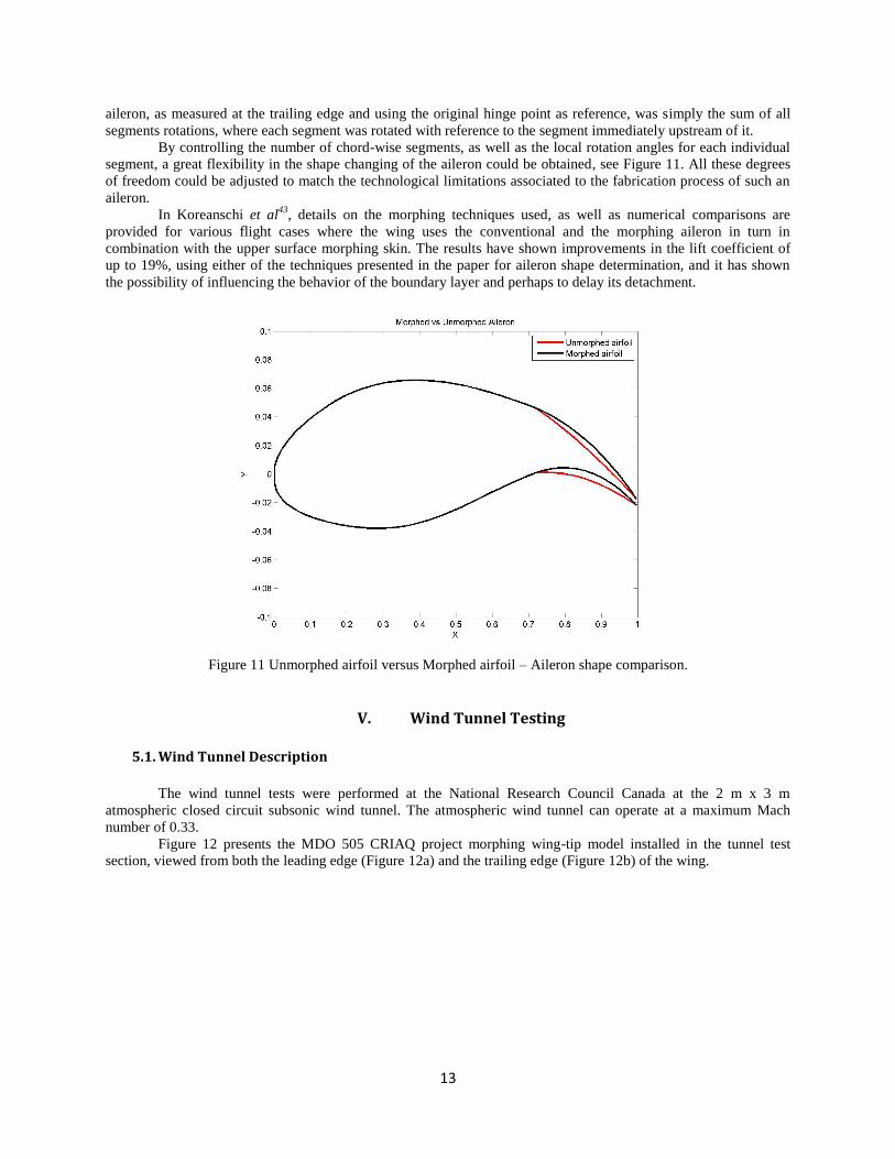
By controlling the number of chord-wise segments, as well as the local rotation angles for each individual
segment, a great flexibility in the shape changing of the aileron could be obtained, see Figure 11. All these degrees
of freedom could be adjusted to match the technological limitations associated to the fabrication process of such an
aileron.
In Koreanschi et al43
, details on the morphing techniques used, as well as numerical comparisons are
provided for various flight cases where the wing uses the conventional and the morphing aileron in turn in
combination with the upper surface morphing skin. The results have shown improvements in the lift coefficient of
up to 19%, using either of the techniques presented in the paper for aileron shape determination, and it has shown
the possibility of influencing the behavior of the boundary layer and perhaps to delay its detachment.
Figure 11 Unmorphed airfoil versus Morphed airfoil – Aileron shape comparison.
V. Wind Tunnel Testing
5.1. Wind Tunnel Description
The wind tunnel tests were performed at the National Research Council Canada at the 2 m x 3 m
atmospheric closed circuit subsonic wind tunnel. The atmospheric wind tunnel can operate at a maximum Mach
number of 0.33.
Figure 12 presents the MDO 505 CRIAQ project morphing wing-tip model installed in the tunnel test
section, viewed from both the leading edge (Figure 12a) and the trailing edge (Figure 12b) of the wing.

14
Figure 12 CRIAQ MDO 505 Project wing model setup in the wind tunnel test section;
5.2. Data Measurement Tools
The upper surface flexible skin of the wing demonstrator was equipped with 32 high precision Kulite
piezoelectric-type transducers, for pressure measurement on the flexible skin. The measured pressures were
processed in real time to determine the laminar-to-turbulent transition location. The sensors were installed in two
chordwise staggered lines (with 16 Kulite sensors on each line), respectively at spanwise positions of 0.600 m and
0.625 m from the wing root section. In addition to the Kulite piezoelectric sensors, 60 static pressure taps were
installed (30 taps on each line), on the wing leading edge, lower surface and aileron, thus providing complete
experimental pressure distribution around the wing cross section at 40% of the wing span. The pressure sensors were
installed in a staggered fashion to minimize any interference in between.
Infra-red (IR) thermography camera visualizations were performed for capturing the transition region over
the entire wing model surface. The wing leading edge, its upper surface flexible skin and the aileron interface were
coated with high emissivity black paint to improve the quality of the IR photographs. The span-wise stations, where
the two pressure sensors lines were installed, were not painted, in order to not influence the pressure reading quality 44
.
The IR thermography visualization allowed the identification of the transition region between laminar and
turbulent regimes, based on the analysis of the model surface temperature. The turbulent flow regime increases the
convective heat transfer between the model and the flow with respect to the laminar boundary layer. As a result, a
flow temperature change, introduced by the wind tunnel heat exchanger system, will cause different temperature
changes over the model, depending on the behavior of the boundary layer (laminar, transitional and turbulent states).
Figure 13 presents an example of the IR visualisation of the wing model upper surface transition, for one flight
condition (Mach number of 0.15, angle of attack of 1o and no aileron deflection) and for both un-morphed (left
figure) and morphed (right figure) skin shapes.

15
Figure 13 IR visualisation of the laminar-to-turbulent transition region on the upper surface for both un-morphed
(left) and morphed (right) skin shapes
The black line represents the average transition line on the wing upper surface, and its variation as function
of the span-wise position can clearly be observed. The two dashed white lines represent the estimated extent of the
transition region, determined as function of the chord-wise temperature gradient existing between laminar and
turbulent regimes. The transition from laminar to turbulent flow occurs over a narrow region and it was
automatically detected for the wing upper surface using a MATLAB code that was specifically developed for the IR
images post-processing45
. The red dot corresponds to the estimated transition in the span-wise section situated at
0.612 m from the root section (40% of the model span), that is half-way between the two Kulite piezoelectric
pressure sensors lines. The accuracy of the transition detection for this section was estimated to ± 2% of the local
chord, based on the known Kulite positions and their thermal signatures in the images.
The experimental measurements also included the use of a wake rake pressure acquisition system, to
measure the wing profile drag at different span-wise positions, and to use a wind tunnel balance that had the aim to
measure the aerodynamic forces and moments.
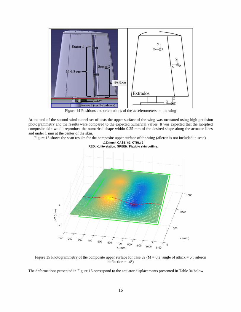
To avoid the possibility of damaging the wing tip model during wind tunnel testing, and to be able to
observe the wing vibration behaviour, three accelerometers were installed. The three accelerometers were installed
in the wing box, aileron and wind tunnel balance respectively as shown in Figure 14.
16
Figure 14 Positions and orientations of the accelerometers on the wing
At the end of the second wind tunnel set of tests the upper surface of the wing was measured using high-precision
photogrammetry and the results were compared to the expected numerical values. It was expected that the morphed
composite skin would reproduce the numerical shape within 0.25 mm of the desired shape along the actuator lines
and under 1 mm at the center of the skin.
Figure 15 shows the scan results for the composite upper surface of the wing (aileron is not included in scan).
Figure 15 Photogrammetry of the composite upper surface for case 82 (M = 0.2, angle of attack = 5°, aileron
deflection = -4°)
The deformations presented in Figure 15 correspond to the actuator displacements presented in Table 3a below.

17
Figures 16 a, b and c present the comparison between target and the actual deformation for case 58 and 550 mm, 950
mm and 1150 mm span position. As it can be seen, the target and the real shape overlap, and the deformation was
considered successful.
Figure 16a Target versus real wing upper surface deformation for case 58 at 550 mm span position
Figure 16b Target versus real wing upper surface deformation for case 58 at 950 mm span position

18
Figure 16c Target versus real wing upper surface deformation for case 58 at 1150 mm span position
The analysis of the measurement data has shown that the composite skin along the actuator lines has reproduced the
desired shape within 0.3 mm, while at the center it has less than 1 mm variation from the desired shape. Overall, the
real morphing composite skin managed to reproduce the numerical shape within the expected limits due to the
precision of the controllers used and to the specific design of the composite skin.
VI. Results and Discussion
The wing demonstrator was tested during three sets of wind tunnel tests. During the first and second sets of
wind tunnel tests, the wing was equipped with the conventional rigid aileron. During the third set of tests, the wing
was equipped with the morphing aileron that was tested in conjunction with the morphing upper surface skin. The
results presented in the first part of this section were obtained during the second set of wind tunnel tests, when the
wing demonstrator was equipped with the morphing upper surface and the conventional aileron. The results
presented in the second part of this section, were obtained during the third set of wind tunnel tests, when the wing
demonstrator was equipped with the morphing upper surface and the morphing aileron. The first set of wind tunnel
tests, consisted of 32 cases tested for the actuators’ and aileron controllers, as well as for Infrared Imaging
calibration.
6.1. Results for the second set of wind tunnel tests – Wing equipped with morphing upper surface
skin and conventional aileron
The two-dimensional aerodynamic optimizations that determined the electrical actuators displacements were
performed with the objective of controlling the extent of laminar flow on the upper surface of the wing model.
These optimizations were performed for several flight conditions (expressed in terms of Mach number, Reynolds
number and angle of attack), and several rigid aileron deflection angles. A total of 97 flight cases were tested for the
wing equipped with morphing upper surface skin and conventional aileron. The optimization and testing was carried
for a range of angles of attack between -5 and 5 degrees, aileron deflections between -7 and 7 and speed range
between Mach 0.15 and Mach 0.25. Due to the large number of tests carried, only twenty-two of the cases that were
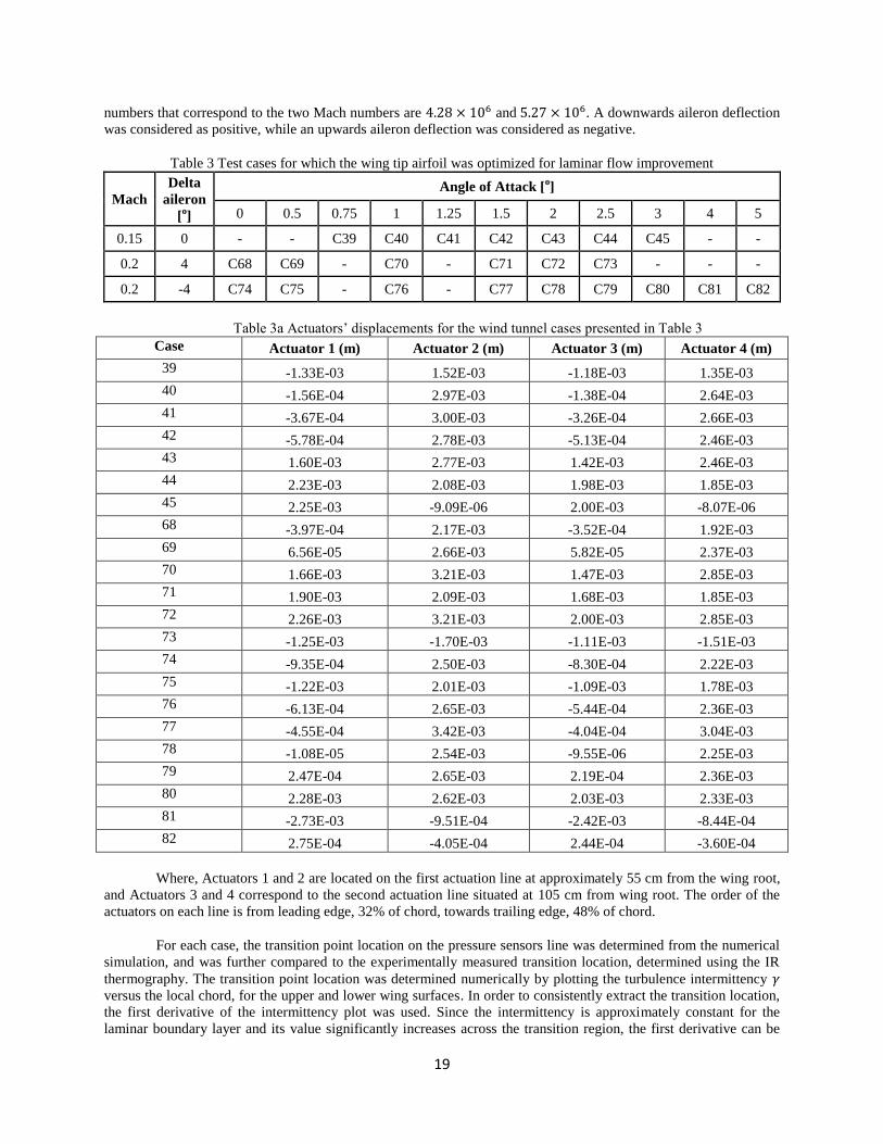
optimized, analysed and experimentally tested for laminar flow increase are presented in Table 3. The Reynolds
19
numbers that correspond to the two Mach numbers are 4.28 × 10⁶ and 5.27 × 10⁶. A downwards aileron deflection
was considered as positive, while an upwards aileron deflection was considered as negative.
Table 3 Test cases for which the wing tip airfoil was optimized for laminar flow improvement
Mach
Delta
aileron
[o]
Angle of Attack [o]
0 0.5 0.75 1 1.25 1.5 2 2.5 3 4 5
0.15 0 - - C39 C40 C41 C42 C43 C44 C45 - -
0.2 4 C68 C69 - C70 - C71 C72 C73 - - -
0.2 -4 C74 C75 - C76 - C77 C78 C79 C80 C81 C82
Table 3a Actuators’ displacements for the wind tunnel cases presented in Table 3
Case Actuator 1 (m) Actuator 2 (m) Actuator 3 (m) Actuator 4 (m)
39 -1.33E-03 1.52E-03 -1.18E-03 1.35E-03
40 -1.56E-04 2.97E-03 -1.38E-04 2.64E-03
41 -3.67E-04 3.00E-03 -3.26E-04 2.66E-03
42 -5.78E-04 2.78E-03 -5.13E-04 2.46E-03
43 1.60E-03 2.77E-03 1.42E-03 2.46E-03
44 2.23E-03 2.08E-03 1.98E-03 1.85E-03
45 2.25E-03 -9.09E-06 2.00E-03 -8.07E-06
68 -3.97E-04 2.17E-03 -3.52E-04 1.92E-03
69 6.56E-05 2.66E-03 5.82E-05 2.37E-03
70 1.66E-03 3.21E-03 1.47E-03 2.85E-03
71 1.90E-03 2.09E-03 1.68E-03 1.85E-03
72 2.26E-03 3.21E-03 2.00E-03 2.85E-03
73 -1.25E-03 -1.70E-03 -1.11E-03 -1.51E-03
74 -9.35E-04 2.50E-03 -8.30E-04 2.22E-03
75 -1.22E-03 2.01E-03 -1.09E-03 1.78E-03
76 -6.13E-04 2.65E-03 -5.44E-04 2.36E-03
77 -4.55E-04 3.42E-03 -4.04E-04 3.04E-03
78 -1.08E-05 2.54E-03 -9.55E-06 2.25E-03
79 2.47E-04 2.65E-03 2.19E-04 2.36E-03
80 2.28E-03 2.62E-03 2.03E-03 2.33E-03
81 -2.73E-03 -9.51E-04 -2.42E-03 -8.44E-04
82 2.75E-04 -4.05E-04 2.44E-04 -3.60E-04
Where, Actuators 1 and 2 are located on the first actuation line at approximately 55 cm from the wing root,
and Actuators 3 and 4 correspond to the second actuation line situated at 105 cm from wing root. The order of the
actuators on each line is from leading edge, 32% of chord, towards trailing edge, 48% of chord.
For each case, the transition point location on the pressure sensors line was determined from the numerical
simulation, and was further compared to the experimentally measured transition location, determined using the IR
thermography. The transition point location was determined numerically by plotting the turbulence intermittency 𝛾
versus the local chord, for the upper and lower wing surfaces. In order to consistently extract the transition location,
the first derivative of the intermittency plot was used. Since the intermittency is approximately constant for the
laminar boundary layer and its value significantly increases across the transition region, the first derivative can be

20
used to identify this region of high gradient. The transition point was considered to be the most upstream point
where the derivative becomes non-zero. As an example, Figure 17 shows the intermittency distribution at 0.612 m
span-wise section, for case C39 original or un-morphed. The laminar-to-turbulent transition corresponds to the
region of high gradient.
Figure 17 Transition detection for Case 39 un-morphed using the turbulence intermittency distribution
6.1.1. Upper surface transition location
In order to evaluate the optimization success of the wing tip demonstrator equipped with morphing upper
surface, the experimental transition region of the morphed wing tip demonstrator was compared to the experimental
transition of the original (un-morphed) wing tip demonstrator. The experimental transition region was provided by
the Infra-Red Thermography data that was recorded during each of the flight case wind tunnel testing.
As such, two parameters were calculated: τ, which represented the difference between the morphed and un-
morphed (original) transition region (TR) upper boundary values and described with how much the onset of the fully
turbulent flow was modified,
UB UBMorphedTr UnmorphedTR
UB upper boundary
(10)
and λ, which represented the difference between the morphed and un-morphed (original) transition region (TR)
lower boundary values and described with how much the boundary of the fully laminar flow was modified.
LB LBMorphedTr UnmorphedTR
LB lower boundary
(11)

21
Table 4 presents the values of extension of the laminar region (λ), contraction of the turbulent region (τ), and the
average transition extension of the un-morphed (original) and morphed transition region for the seven cases from
Table 3.
Table 4 Presentation of (τ) and (λ) parameters for each of the flight cases from Table 3
Case No Extension of the Laminar
region (% of chord) (λ) Transition Region average
(% of chord)
Contraction of the turbulent
region (% of chord) (τ)
39 -0.09% -0.09% -0.09%
40 3.76% 1.76% 2.76%
41 3.79% 1.79% 2.79%
42 2.19% 2.19% 2.19%
43 3.13% 3.13% 3.13%
44 0.98% 2.98% 1.98%
45 0.29% 0.29% 0.29%
68 1.95% 1.95% 1.95%
69 1.21% 1.21% 1.21%
70 3.33% 1.33% 2.33%
71 8.39% 6.39% 7.39%
72 7.65% 5.65% 6.65%
73 -0.26% -2.26% -1.26%
74 N/A N/A N/A
75 -4.68% -2.68% -3.68%
76 -3.24% -3.24% -3.24%
77 -1.63% 0.37% -0.63%
78 -0.87% -0.87% -0.87%
79 -1.78% -1.78% -1.78%
80 2.19% 2.19% 2.19%
81 -3.28% -3.28% -3.28%
82 0.24% 0.24% 0.24%
In table 4 it can be observed that 14 cases out of the 22 presented have obtained both extension of the laminar region
and contraction of the turbulent region, having in effect an enlarged transition region. The maximum extension was
obtain for case 71, at Mach 0.2, angle of attack 1.5° and aileron deflection 4
° down, where the laminar extension is
8.39% of the chord and the turbulent region contraction is 6.39% of the chord, closely followed by case 72. The
other 7 cases, mostly for the wing with aileron deflection up, have obtained a contraction of the transition region.
In order to better visualize the results presented in table 4, figures 18 to 20 (a) present the comparison between the
experimental unmorphed (original) and morphed transition intervals, while figures 18 to 20 (b) present the
comparison between the numerical and experimental unmorphed (original) transition, in order to estimate the degree
of accuracy of the numerical analysis. The accuracy level of the numerical values was calculated as an absolute
difference between the numerically calculated transition and the closest boundary of the experimental transition
interval. It was considered that if the numerical transition was situated inside the experimental transition region, the
error would be considered 0.

22
𝑇𝑟𝑒𝑟𝑟𝑜𝑟 = 𝑇𝑟𝑛𝑢𝑚𝑒𝑟𝑖𝑐𝑎𝑙 − 𝑇𝑟𝑒𝑥𝑝𝑒𝑟𝑖𝑚𝑒𝑛𝑡𝑎𝑙_𝑢𝑝𝑝𝑒𝑟_𝑏𝑜𝑢𝑛𝑑𝑎𝑟𝑦 (12)
Figure 18(a) shows the unmorphed (original) and morphed transition IR experimental results for cases C39 to
C45 (Mach number of 0.15, no aileron deflection and angles of attack between 0.75 and 3°).
Figure 18(a) Comparison between unmorphed (Original) and morphed IR experimental transition detection
for the station located at 40% of the span for cases C39 – C45
Figure 18(b) Comparison between numerical and IR experimental transition detection
for the station located at 40% of the span for cases C39 – C45 – unmorphed (original) state of the wing
In Figure 18(b), it can be seen that a reasonable agreement exists between the experimental and the
numerically determined transition point location at the pressure sensors section for the un-morphed (original) wing.
For these cases (C39 to C45, with no aileron deflection), the un-morphed (original) wing error is around 6% of the
local chord.
For the morphed geometries results the agreement between the numerical and IR transition positions is
slightly better than for the un-morphed wing, with the average error being approximately 5% of the local chord.
As presented in table 4, Figure 18(a) shows that the IR experimental results show a successful improvement
of laminar flow for the section of interest. The transition is delayed towards the trailing edge by 3-4% of the chord.
40,00%
42,00%
44,00%
46,00%
48,00%
50,00%
52,00%
54,00%
56,00%
0 0,5 1 1,5 2 2,5 3 3,5
Up
pe
r&Lo
we
r B
ou
nd
arie
s o
f th
e
tran
siti
on
re
gio
n (
%c)
Angle of attack
Experimental Unmorphed Wing Experimental Morphed upper Surface Wing
40,00%
42,00%
44,00%
46,00%
48,00%
50,00%
52,00%
54,00%
56,00%
58,00%
0 0,5 1 1,5 2 2,5 3 3,5
Up
pe
r&Lo
we
r B
ou
nd
arie
s o
f th
e
tran
siti
on
re
gio
n (
%c)
Angle of attack
Experimental Unmorphed Wing Numeric Unmorphed Wing
23
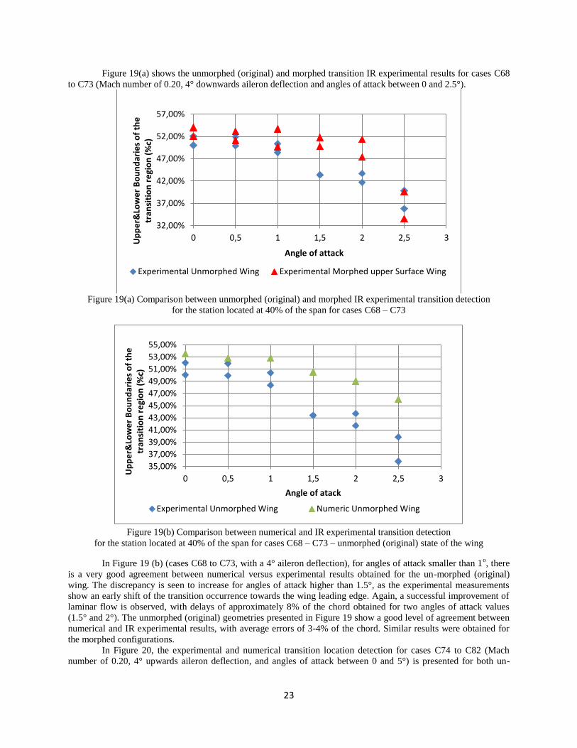
Figure 19(a) shows the unmorphed (original) and morphed transition IR experimental results for cases C68
to C73 (Mach number of 0.20, 4° downwards aileron deflection and angles of attack between 0 and 2.5°).
Figure 19(a) Comparison between unmorphed (original) and morphed IR experimental transition detection
for the station located at 40% of the span for cases C68 – C73
Figure 19(b) Comparison between numerical and IR experimental transition detection
for the station located at 40% of the span for cases C68 – C73 – unmorphed (original) state of the wing
In Figure 19 (b) (cases C68 to C73, with a 4° aileron deflection), for angles of attack smaller than 1o, there
is a very good agreement between numerical versus experimental results obtained for the un-morphed (original)
wing. The discrepancy is seen to increase for angles of attack higher than 1.5°, as the experimental measurements
show an early shift of the transition occurrence towards the wing leading edge. Again, a successful improvement of
laminar flow is observed, with delays of approximately 8% of the chord obtained for two angles of attack values
(1.5° and 2°). The unmorphed (original) geometries presented in Figure 19 show a good level of agreement between
numerical and IR experimental results, with average errors of 3-4% of the chord. Similar results were obtained for
the morphed configurations.
In Figure 20, the experimental and numerical transition location detection for cases C74 to C82 (Mach
number of 0.20, 4° upwards aileron deflection, and angles of attack between 0 and 5°) is presented for both un-
32,00%
37,00%
42,00%
47,00%
52,00%
57,00%
0 0,5 1 1,5 2 2,5 3Up
pe
r&Lo
we
r B
ou
nd
arie
s o
f th
e
tran
siti
on
re
gio
n (
%c)
Angle of attack
Experimental Unmorphed Wing Experimental Morphed upper Surface Wing
35,00%
37,00%
39,00%
41,00%
43,00%
45,00%
47,00%
49,00%
51,00%
53,00%
55,00%
0 0,5 1 1,5 2 2,5 3
Up
pe
r&Lo
we
r B
ou
nd
arie
s o
f th
e
tran
siti
on
re
gio
n (
%c)
Angle of atack
Experimental Unmorphed Wing Numeric Unmorphed Wing

24
morphed (original) and morphed wing geometries. No IR experimental data was available for cases C74 (0° angle of
attack).
Figure 20(a) Comparison between unmorphed (original) and morphed IR experimental transition detection
for the station located at 40% of the span for cases C74 – C82
Figure 20(b) Comparison between numerical and IR experimental transition detection
for the station located at 40% of the span for cases C74 – C82 - unmorphed (original) state of the wing
For cases C74 to C82 (-4° aileron deflection), presented in Figure 17, there is a good agreement between
the IR data and the numerical results for the un-morphed (original) wing (transition position errors of less than 5%
of the chord).
With the exception of case 80, the laminar flow delay predicted by the numerical results is not observed in
the IR measurements.
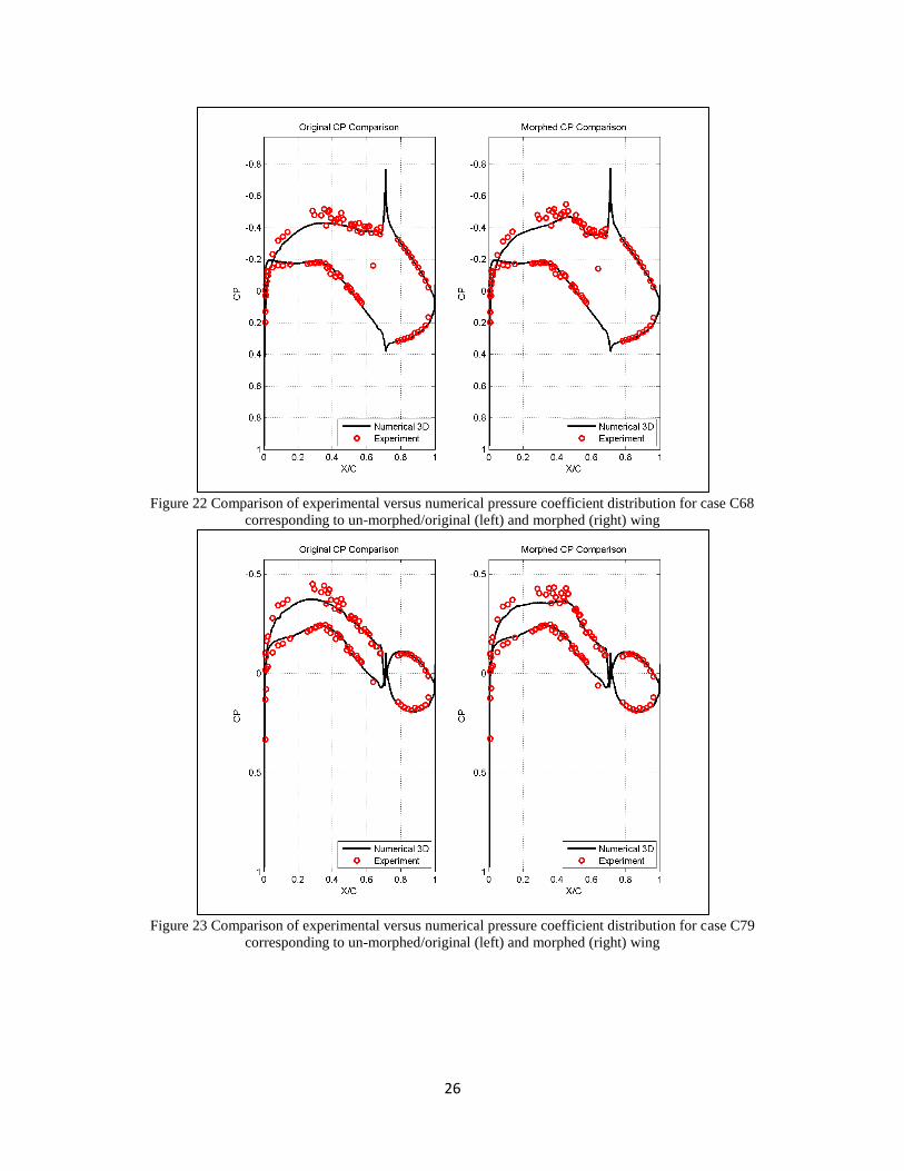
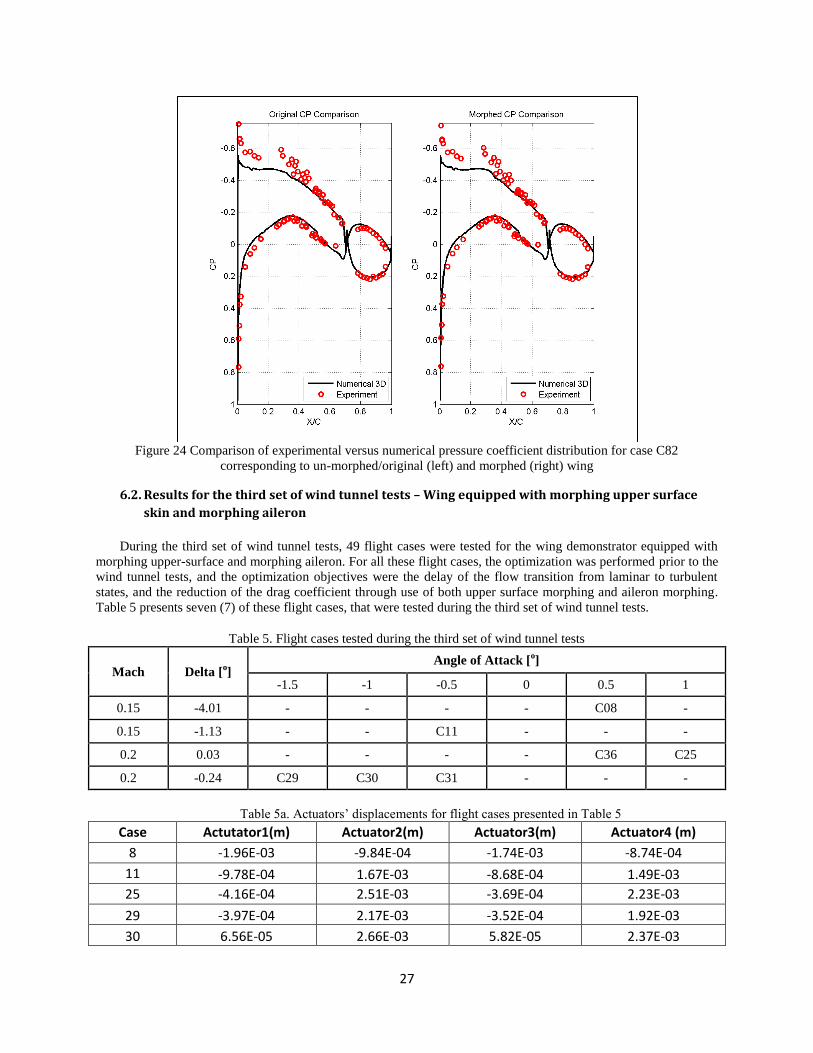
6.1.2. Pressure coefficient distribution comparisons
A comparison between the experimental and numerical pressure coefficient distributions for the section located
at 40% of the wing span is presented in Figures 21 to 24, for the following 4 cases: C40 (Mach number of 0.15,
angle of attack of 1°, and no aileron deflection), C68 (Mach number of 0.20, angle of attack of 0°, and 4° aileron
deflection) and for C79 and C82 (Mach number of 0.20, angles of attack of 2.5° and 5°, and -4° aileron deflection).
20,00%
25,00%
30,00%
35,00%
40,00%
45,00%
50,00%
0 1 2 3 4 5 6Up
pe
r&Lo
we
r B
ou
nd
arie
s o
f th
e
tran
siti
on
re
gio
n (
%c)
Angle of attack
Experimental Unmorphed Wing Experimental Morphed upper Surface Wing
20,00%
25,00%
30,00%
35,00%
40,00%
45,00%
50,00%
55,00%
0 1 2 3 4 5 6
Up
pe
r&Lo
we
r B
ou
nd
arie
s o
f th
e
tran
siti
on
re
gio
n (
%c)
Case number
Experimental Unmorphed Wing Numeric Unmorphed Wing

25
Very good agreement exits between numerical predictions and the wind tunnel test measurements for the two
sets of results given by case C40 and C 68 (Figures 21 and 22). The influence of the upper skin shape change can be
observed from the differences between the un-morphed/original (left) and morphed (right) pressure coefficient
distributions, for the chordwise interval between 25% and 60% of the chord. The skin morphing extends the region
where the air accelerates over the upper surface, thus creating more favourable conditions for laminar flow, this
effect being clearly visible in the two figures.
For cases C79 and C82 (shown in Figures 23 and 24), a small difference exists in the upper surface pressure
coefficient up to 50% of the chord, and very good agreement exists between the numerical and experimental results
for the aileron, rigid lower skin and the upper surface downstream of 50% of the chord. Once again, the influence of
the morphing skin is clearly observable by comparing the left (un-morphed/original) and right (morphed) pressure
distributions on both figures.
Figure 21 Comparison of experimental versus numerical pressure coefficient distribution for case C40
corresponding to un-morphed/original (left) and morphed (right) wing
26
Figure 22 Comparison of experimental versus numerical pressure coefficient distribution for case C68
corresponding to un-morphed/original (left) and morphed (right) wing
Figure 23 Comparison of experimental versus numerical pressure coefficient distribution for case C79
corresponding to un-morphed/original (left) and morphed (right) wing
27
Figure 24 Comparison of experimental versus numerical pressure coefficient distribution for case C82
corresponding to un-morphed/original (left) and morphed (right) wing
6.2. Results for the third set of wind tunnel tests – Wing equipped with morphing upper surface
skin and morphing aileron
During the third set of wind tunnel tests, 49 flight cases were tested for the wing demonstrator equipped with
morphing upper-surface and morphing aileron. For all these flight cases, the optimization was performed prior to the
wind tunnel tests, and the optimization objectives were the delay of the flow transition from laminar to turbulent
states, and the reduction of the drag coefficient through use of both upper surface morphing and aileron morphing.
Table 5 presents seven (7) of these flight cases, that were tested during the third set of wind tunnel tests.
Table 5. Flight cases tested during the third set of wind tunnel tests
Mach Delta [o]
Angle of Attack [o]
-1.5 -1 -0.5 0 0.5 1
0.15 -4.01 - - - - C08 -
0.15 -1.13 - - C11 - - -
0.2 0.03 - - - - C36 C25
0.2 -0.24 C29 C30 C31 - - -
Table 5a. Actuators’ displacements for flight cases presented in Table 5
Case Actutator1(m) Actuator2(m) Actuator3(m) Actuator4 (m)
8 -1.96E-03 -9.84E-04 -1.74E-03 -8.74E-04
11 -9.78E-04 1.67E-03 -8.68E-04 1.49E-03
25 -4.16E-04 2.51E-03 -3.69E-04 2.23E-03
29 -3.97E-04 2.17E-03 -3.52E-04 1.92E-03
30 6.56E-05 2.66E-03 5.82E-05 2.37E-03
28
31 1.66E-03 3.21E-03 1.47E-03 2.85E-03
36 -3.97E-04 2.17E-03 -3.52E-04 1.92E-03
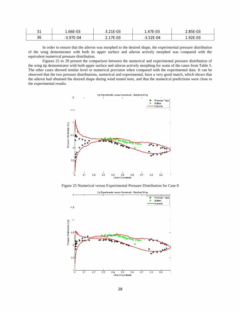
In order to ensure that the aileron was morphed to the desired shape, the experimental pressure distribution
of the wing demonstrator with both its upper surface and aileron actively morphed was compared with the
equivalent numerical pressure distribution.
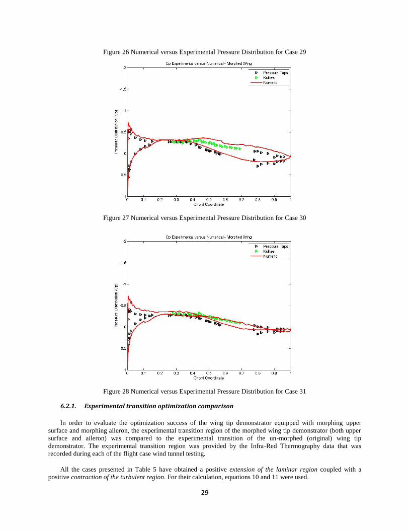
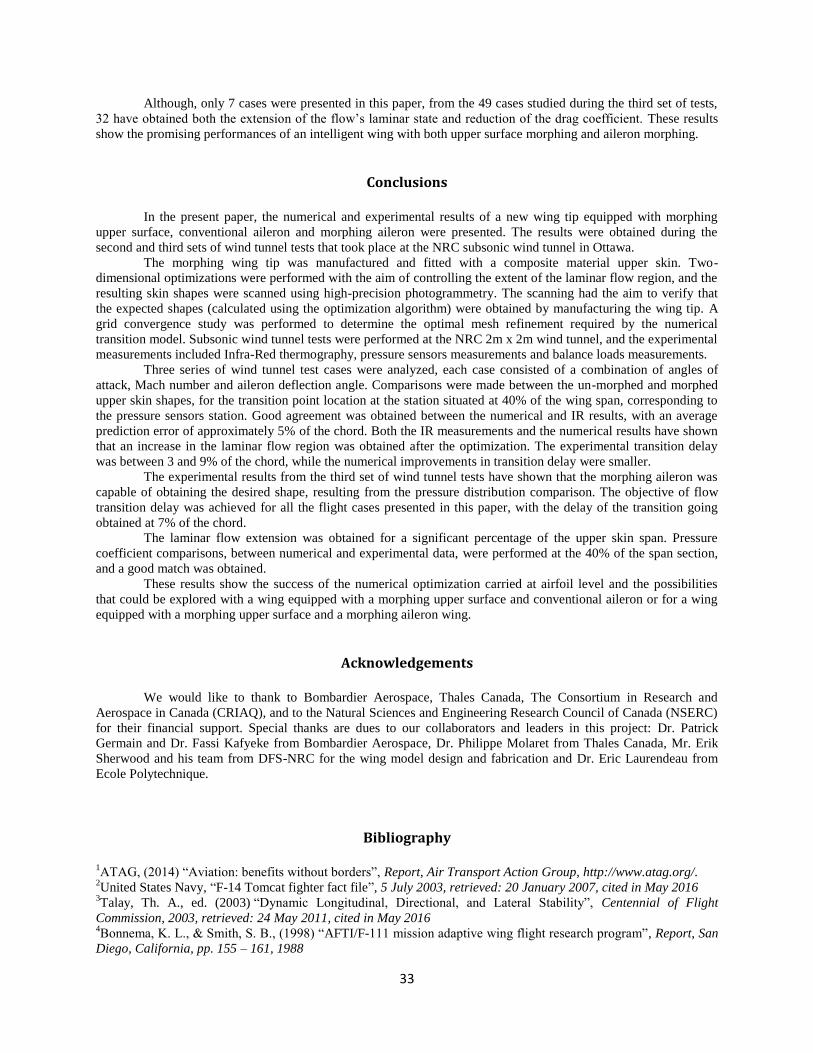
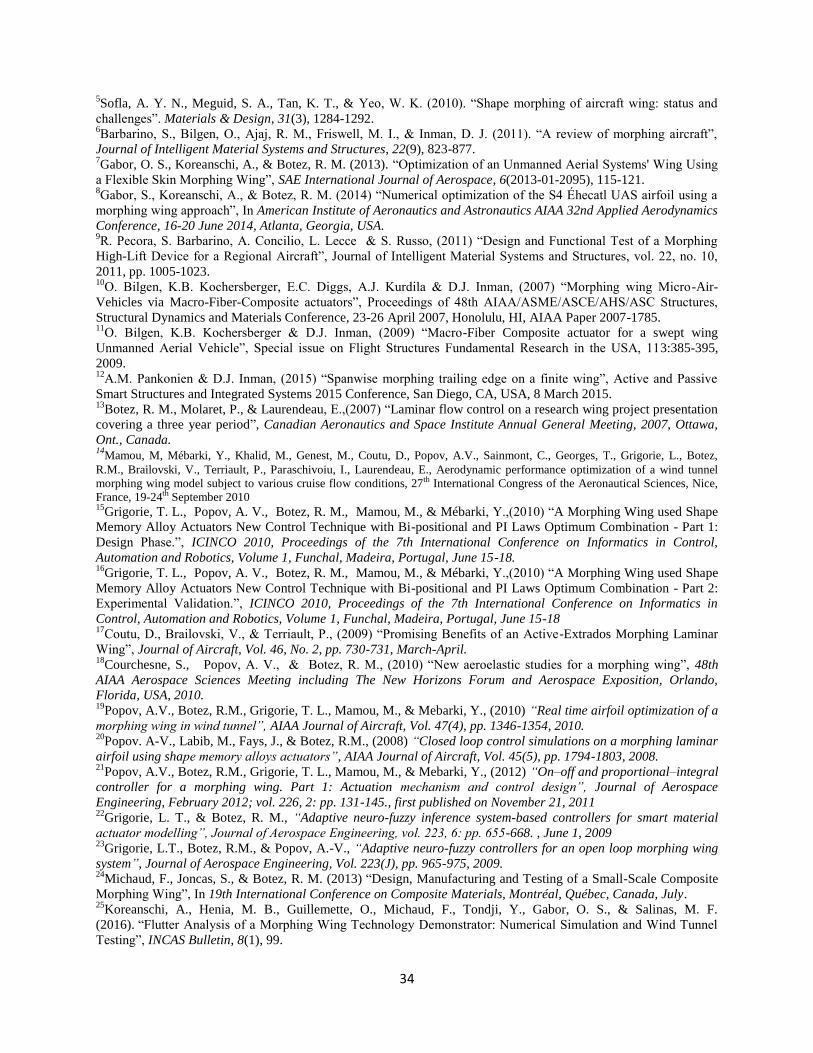
Figures 25 to 28 present the comparison between the numerical and experimental pressure distribution of
the wing tip demonstrator with both upper surface and aileron actively morphing for some of the cases from Table 5.
The other cases showed similar level or numerical precision when compared with the experimental data. It can be
observed that the two pressure distributions, numerical and experimental, have a very good match, which shows that
the aileron had obtained the desired shape during wind tunnel tests, and that the numerical predictions were close to
the experimental results.
Figure 25 Numerical versus Experimental Pressure Distribution for Case 8
29
Figure 26 Numerical versus Experimental Pressure Distribution for Case 29
Figure 27 Numerical versus Experimental Pressure Distribution for Case 30
Figure 28 Numerical versus Experimental Pressure Distribution for Case 31
6.2.1. Experimental transition optimization comparison
In order to evaluate the optimization success of the wing tip demonstrator equipped with morphing upper
surface and morphing aileron, the experimental transition region of the morphed wing tip demonstrator (both upper
surface and aileron) was compared to the experimental transition of the un-morphed (original) wing tip
demonstrator. The experimental transition region was provided by the Infra-Red Thermography data that was
recorded during each of the flight case wind tunnel testing.
All the cases presented in Table 5 have obtained a positive extension of the laminar region coupled with a
positive contraction of the turbulent region. For their calculation, equations 10 and 11 were used.

30
UB UBMorphedTr UnmorphedTR
UB upper boundary
LB LBMorphedTr UnmorphedTR
LB lower boundary
Table 6 presents the values of extension of the laminar region (λ), contraction of the turbulent region (τ), and the
average transition extension of the un-morphed (original) and morphed transition region for the seven cases from
Table 5.
Table 6 Presentation of (τ) and (λ) parameters for each of the flight cases from Table 5
Case No Extension of the Laminar
region (% of chord) (λ) Transition Region average
(% of chord)
Contraction of the turbulent
region (% of chord) (τ)
8 2.84% 3.84% 4.84%
11 0.92% 1.92% 2.92%
25 6.43% 6.43% 6.43%
29 1.80% 0.80% -0.20%
30 3.87% 2.87% 1.87%
31 1.71% 1.71% 1.71%
36 1.66% 2.66% 3.66%
Flight case 29 gives a small negative contraction of the turbulent region τ that is counterbalanced by almost
2% of the chord of laminar region extension.
The other flight cases gave an extension of the laminar region (λ) of up to 6.5% of the chord, and a
contraction of the turbulent region (τ) of up to 5% of the chord.
Figure 29 presents the transition region for the un-morphed (original) and morphed wing for all the cases
discussed above. In this figure, a delay of the transition region between un-morphed and morphed states can be
observed towards the trailing edge section of the wing. This transition delay is due to having both the upper surface
skin and aileron morphing at the same time.

31
Figure 29 Comparison between un-morphed and morphed states of the wing’s upper surface when aileron is
morphed – experimental data
The influence of the morphing aileron and morphing wing upper surface were observed on the behaviour of
the boundary layer through extension of the laminar state of the flow, but they also influenced the behaviour of the
drag coefficient of the wing. Figure 30 presents the effects that the morphing of the wing upper surface and of the
aileron had on the drag, as a comparison between the morphed and un-morphed states of the wing tip. Figure 31
presents the relative difference between the two states of the wing for the drag reduction, while Figure 32 presents
the influence morphing has had on the Lift-Drag relation. All coefficients are presented in counts, where 1 count =
1e-3
.
Figure 30 Effect of the morphing upper surface and morphing aileron on the drag coefficient
30,00%
35,00%
40,00%
45,00%
50,00%
55,00%
60,00%
65,00%
0 1 2 3 4 5 6 7 8
Up
pe
r&Lo
we
r B
ou
nd
arie
s o
f th
e t
ran
siti
on
re
gio
n (
%c)
Case number
Unmorphed Wing with Morphed Aileron Morphed Wing with Morphed Aileron
0
5
10
15
20
25
30
0 5 10 15 20 25 30 35 40
dra
gc c
oef
fici
ent
(co
un
ts)
Case
Wing with morphed aileron and unmorphed upper surface
Wing with morphed aileron and morphed upper surface

32
Figure 31 Relative value of the drag coefficient reduction
The relative drag reduction was calculated as shown in equation (9):
𝐶𝐷 𝑟𝑒𝑑𝑢𝑐𝑡𝑖𝑜𝑛 =(𝐶𝐷 𝑚𝑜𝑟𝑝ℎ𝑒𝑑 − 𝐶𝐷 𝑢𝑛𝑚𝑜𝑟𝑝ℎ𝑒𝑑)
𝐶𝐷 𝑢𝑛𝑚𝑜𝑟𝑝ℎ𝑒𝑑
∙ 100 (9)
Figure 32 Lift versus Drag comparison between morphed and un-morphed states
Based on the experimental results, the coupled morphing of upper surface and aileron has achieved a drag
coefficient reduction of up to 9.5%, even when the aileron deflections were small. This fact demonstrates that a
smoother slope for the wing camber line, even at small deflections, has a high impact on the wing’s performances.
-10,00%
-9,00%
-8,00%
-7,00%
-6,00%
-5,00%
-4,00%
-3,00%
-2,00%
-1,00%
0,00%
0 5 10 15 20 25 30 35 40
dra
f co
effi
cien
t re
du
ctio
n
Case
Drag coefficient reduction
Drag coefficient reduction
0
50
100
150
200
250
0 5 10 15 20 25 30
Lift
co
effi
cien
t (c
ou
nts
)
Drag coefficient (counts)
Lift to Drag
Wing with morphed aileron and unmorphed upper sorphed
Wing with morphed aileron and morphed upper surface
33
Although, only 7 cases were presented in this paper, from the 49 cases studied during the third set of tests,
32 have obtained both the extension of the flow’s laminar state and reduction of the drag coefficient. These results
show the promising performances of an intelligent wing with both upper surface morphing and aileron morphing.
Conclusions
In the present paper, the numerical and experimental results of a new wing tip equipped with morphing
upper surface, conventional aileron and morphing aileron were presented. The results were obtained during the
second and third sets of wind tunnel tests that took place at the NRC subsonic wind tunnel in Ottawa.
The morphing wing tip was manufactured and fitted with a composite material upper skin. Two-
dimensional optimizations were performed with the aim of controlling the extent of the laminar flow region, and the
resulting skin shapes were scanned using high-precision photogrammetry. The scanning had the aim to verify that
the expected shapes (calculated using the optimization algorithm) were obtained by manufacturing the wing tip. A
grid convergence study was performed to determine the optimal mesh refinement required by the numerical
transition model. Subsonic wind tunnel tests were performed at the NRC 2m x 2m wind tunnel, and the experimental
measurements included Infra-Red thermography, pressure sensors measurements and balance loads measurements.
Three series of wind tunnel test cases were analyzed, each case consisted of a combination of angles of
attack, Mach number and aileron deflection angle. Comparisons were made between the un-morphed and morphed
upper skin shapes, for the transition point location at the station situated at 40% of the wing span, corresponding to
the pressure sensors station. Good agreement was obtained between the numerical and IR results, with an average
prediction error of approximately 5% of the chord. Both the IR measurements and the numerical results have shown
that an increase in the laminar flow region was obtained after the optimization. The experimental transition delay
was between 3 and 9% of the chord, while the numerical improvements in transition delay were smaller.
The experimental results from the third set of wind tunnel tests have shown that the morphing aileron was
capable of obtaining the desired shape, resulting from the pressure distribution comparison. The objective of flow
transition delay was achieved for all the flight cases presented in this paper, with the delay of the transition going
obtained at 7% of the chord.
The laminar flow extension was obtained for a significant percentage of the upper skin span. Pressure
coefficient comparisons, between numerical and experimental data, were performed at the 40% of the span section,
and a good match was obtained.
These results show the success of the numerical optimization carried at airfoil level and the possibilities
that could be explored with a wing equipped with a morphing upper surface and conventional aileron or for a wing
equipped with a morphing upper surface and a morphing aileron wing.
Acknowledgements
We would like to thank to Bombardier Aerospace, Thales Canada, The Consortium in Research and
Aerospace in Canada (CRIAQ), and to the Natural Sciences and Engineering Research Council of Canada (NSERC)
for their financial support. Special thanks are dues to our collaborators and leaders in this project: Dr. Patrick
Germain and Dr. Fassi Kafyeke from Bombardier Aerospace, Dr. Philippe Molaret from Thales Canada, Mr. Erik
Sherwood and his team from DFS-NRC for the wing model design and fabrication and Dr. Eric Laurendeau from
Ecole Polytechnique.
Bibliography
1ATAG, (2014) “Aviation: benefits without borders”, Report, Air Transport Action Group, http://www.atag.org/.
2United States Navy, “F-14 Tomcat fighter fact file”, 5 July 2003, retrieved: 20 January 2007, cited in May 2016
3Talay, Th. A., ed. (2003) “Dynamic Longitudinal, Directional, and Lateral Stability”, Centennial of Flight
Commission, 2003, retrieved: 24 May 2011, cited in May 2016 4Bonnema, K. L., & Smith, S. B., (1998) “AFTI/F-111 mission adaptive wing flight research program”, Report, San
Diego, California, pp. 155 – 161, 1988
34
5Sofla, A. Y. N., Meguid, S. A., Tan, K. T., & Yeo, W. K. (2010). “Shape morphing of aircraft wing: status and
challenges”. Materials & Design, 31(3), 1284-1292. 6Barbarino, S., Bilgen, O., Ajaj, R. M., Friswell, M. I., & Inman, D. J. (2011). “A review of morphing aircraft”,
Journal of Intelligent Material Systems and Structures, 22(9), 823-877. 7Gabor, O. S., Koreanschi, A., & Botez, R. M. (2013). “Optimization of an Unmanned Aerial Systems' Wing Using
a Flexible Skin Morphing Wing”, SAE International Journal of Aerospace, 6(2013-01-2095), 115-121. 8Gabor, S., Koreanschi, A., & Botez, R. M. (2014) “Numerical optimization of the S4 Éhecatl UAS airfoil using a
morphing wing approach”, In American Institute of Aeronautics and Astronautics AIAA 32nd Applied Aerodynamics
Conference, 16-20 June 2014, Atlanta, Georgia, USA. 9R. Pecora, S. Barbarino, A. Concilio, L. Lecce & S. Russo, (2011) “Design and Functional Test of a Morphing
High-Lift Device for a Regional Aircraft”, Journal of Intelligent Material Systems and Structures, vol. 22, no. 10,
2011, pp. 1005-1023. 10
O. Bilgen, K.B. Kochersberger, E.C. Diggs, A.J. Kurdila & D.J. Inman, (2007) “Morphing wing Micro-Air-
Vehicles via Macro-Fiber-Composite actuators”, Proceedings of 48th AIAA/ASME/ASCE/AHS/ASC Structures,
Structural Dynamics and Materials Conference, 23-26 April 2007, Honolulu, HI, AIAA Paper 2007-1785. 11
O. Bilgen, K.B. Kochersberger & D.J. Inman, (2009) “Macro-Fiber Composite actuator for a swept wing
Unmanned Aerial Vehicle”, Special issue on Flight Structures Fundamental Research in the USA, 113:385-395,
2009. 12
A.M. Pankonien & D.J. Inman, (2015) “Spanwise morphing trailing edge on a finite wing”, Active and Passive
Smart Structures and Integrated Systems 2015 Conference, San Diego, CA, USA, 8 March 2015. 13
Botez, R. M., Molaret, P., & Laurendeau, E.,(2007) “Laminar flow control on a research wing project presentation
covering a three year period”, Canadian Aeronautics and Space Institute Annual General Meeting, 2007, Ottawa,
Ont., Canada. 14
Mamou, M, Mébarki, Y., Khalid, M., Genest, M., Coutu, D., Popov, A.V., Sainmont, C., Georges, T., Grigorie, L., Botez,
R.M., Brailovski, V., Terriault, P., Paraschivoiu, I., Laurendeau, E., Aerodynamic performance optimization of a wind tunnel
morphing wing model subject to various cruise flow conditions, 27th International Congress of the Aeronautical Sciences, Nice,
France, 19-24th September 2010 15
Grigorie, T. L., Popov, A. V., Botez, R. M., Mamou, M., & Mébarki, Y.,(2010) “A Morphing Wing used Shape
Memory Alloy Actuators New Control Technique with Bi-positional and PI Laws Optimum Combination - Part 1:
Design Phase.”, ICINCO 2010, Proceedings of the 7th International Conference on Informatics in Control,
Automation and Robotics, Volume 1, Funchal, Madeira, Portugal, June 15-18. 16
Grigorie, T. L., Popov, A. V., Botez, R. M., Mamou, M., & Mébarki, Y.,(2010) “A Morphing Wing used Shape
Memory Alloy Actuators New Control Technique with Bi-positional and PI Laws Optimum Combination - Part 2:
Experimental Validation.”, ICINCO 2010, Proceedings of the 7th International Conference on Informatics in
Control, Automation and Robotics, Volume 1, Funchal, Madeira, Portugal, June 15-18 17
Coutu, D., Brailovski, V., & Terriault, P., (2009) “Promising Benefits of an Active-Extrados Morphing Laminar
Wing”, Journal of Aircraft, Vol. 46, No. 2, pp. 730-731, March-April. 18
Courchesne, S., Popov, A. V., & Botez, R. M., (2010) “New aeroelastic studies for a morphing wing”, 48th
AIAA Aerospace Sciences Meeting including The New Horizons Forum and Aerospace Exposition, Orlando,
Florida, USA, 2010. 19
Popov, A.V., Botez, R.M., Grigorie, T. L., Mamou, M., & Mebarki, Y., (2010) “Real time airfoil optimization of a
morphing wing in wind tunnel”, AIAA Journal of Aircraft, Vol. 47(4), pp. 1346-1354, 2010. 20
Popov. A-V., Labib, M., Fays, J., & Botez, R.M., (2008) “Closed loop control simulations on a morphing laminar
airfoil using shape memory alloys actuators”, AIAA Journal of Aircraft, Vol. 45(5), pp. 1794-1803, 2008. 21
Popov, A.V., Botez, R.M., Grigorie, T. L., Mamou, M., & Mebarki, Y., (2012) “On–off and proportional–integral
controller for a morphing wing. Part 1: Actuation mechanism and control design”, Journal of Aerospace
Engineering, February 2012; vol. 226, 2: pp. 131-145., first published on November 21, 2011 22
Grigorie, L. T., & Botez, R. M., “Adaptive neuro-fuzzy inference system-based controllers for smart material
actuator modelling”, Journal of Aerospace Engineering, vol. 223, 6: pp. 655-668. , June 1, 2009 23
Grigorie, L.T., Botez, R.M., & Popov, A.-V., “Adaptive neuro-fuzzy controllers for an open loop morphing wing
system”, Journal of Aerospace Engineering, Vol. 223(J), pp. 965-975, 2009. 24
Michaud, F., Joncas, S., & Botez, R. M. (2013) “Design, Manufacturing and Testing of a Small-Scale Composite
Morphing Wing”, In 19th International Conference on Composite Materials, Montréal, Québec, Canada, July. 25
Koreanschi, A., Henia, M. B., Guillemette, O., Michaud, F., Tondji, Y., Gabor, O. S., & Salinas, M. F.
(2016). “Flutter Analysis of a Morphing Wing Technology Demonstrator: Numerical Simulation and Wind Tunnel
Testing”, INCAS Bulletin, 8(1), 99.
35
26Kammegne, M. J. T., Nguyen, D. H., Botez, R. M., & Grigorie, T. L. (2015) “Control validation of a morphing
wing in an open loop architecture”, AIAA Modeling and Simulation Technologies Conference, Aviation Forum. 27
Kammegne, Michel Joël Tchatchueng, Hamdi Belhadj, Duc-Hien Nguyen, & Ruxandra Mihaela Botez. (2015)
"Nonlinear Control Logic for an Actuator to Morph a Wing: Design and Experimental Validation." IASTED
Modelling, Identification and Control Conference, 2015. 28
F. Michaud, “Design and Optimization of a Composite Skin for an Adaptive Wing”, Master of Science Thesis,
Ecole de technologie superieure, Montreal, Canada, 2014. 29
R. Pecora, F. Amoroso, M. Magnifico, I. Dimino, A. Concilio, KRISTINA: Kinematic Rib based Structural system
for Innovative Adaptive trailing edge, SPIE Smart Structures/NDE, Las Vegas, Nevada (USA) March 2016. Proc.
SPIE 9801, Industrial and Commercial Applications of Smart Structures Technologies 2016, 980107 (April 16,
2016); doi:10.1117/12.2218516 30
I. Dimino, A. Concilio and R. Pecora, Safety and Reliability Aspects of an Adaptive Trailing Edge Device
(ATED), 24th AIAA/AHS Adaptive Structures Conference, AIAA SciTech, 4-8 Jan 2016 31
Barbarino, S., Pecora, R., Lecce, L., Concillio, A., Ameduri, S., & De Rosa, L., “Airfoil structural morphing based
on SMA actuator series: numerical and experimental studies”, Journal of Intelligent Material Systems and
Structures, Vol. 22, pp. 987-1003, 2001 32
Ameduri, S., Brindisi, A., Tiseo, B., Concilio, A., & Pecora, R., (2002) “Optimization and integration of shape
memory alloy (SMA) based elastic actuators within a morphing flap architecture”, Journal of Intelligent Material
Systems and Structures, Vol. 23, issue 4, pp. 381-396, 2002 33
Diodati, G., Concilio, A., Ricci, S., de Gaspari, A., Liauzun, C., & Godard, J.L., (2013) “Estimated performance of
an adaptive trailing-edge device aimed at reducing the fuel consumption on a medium-size aircraft”, Smart
Structures/NDE conference, 10-14 March 2013, San Diego, California,USA, 2013 34
G. Amendola, I. Dimino, M. Magnifico and R. Pecora, (2016), “Distributed actuation concepts for a morphing
aileron device”, The Aeronautical Journal, Vol. 120, No. 1231, pp. 1365-1385 doi 10.1017/aer.2016.64 35
Koreanschi, A., Sugar-Gabor, O. & Botez, R.M. (2016) “Numerical and experimental validation of a morphed
wing geometry using Price-Païdoussis wind-tunnel testing”. The Aeronautical Journal, 120, pp 757-795
doi:10.1017/aer.2016.30 36
Gabor, O. S., Koreanschi, A., & Botez, R. M. (2012) “Low-speed aerodynamic characteristics improvement of
ATR 42 airfoil using a morphing wing approach” In IECON 2012-38th Annual Conference on IEEE Industrial
Electronics Society (pp. 5451-5456). IEEE. 37
Koreanschi, A., Şugar Gabor, O., Acotto, J., Brianchon, G., Portier, G., Botez, R.M., Mamou, M., & Mebarki, Y.,
(2016) “Optimization and Design of a Morphing Aircraft Wing
Tip Demonstrator for Drag Reduction at Low Speed, Part I – Aerodynamic Optimization Using 3 Algorithms:
Genetic, Bee Colony and Gradient Descent”, This article was accepted for publication in The Chinese Journal of
Aeronautics 38
F.R. Menter, (1994) “Two-Equation Eddy-Viscosity Turbulence Models for Engineering Applications”, AIAA
Journal, Vol. 32, No.8, pp. 1598-1605. 39
R.B. Langtry & F.R. Menter, (2009) “Correlation-Based Transition Modeling for Unstructured Parallelized
Computational Fluid Dynamics Codes”, AIAA Journal, Vol. 47, No. 12, pp. 2894-2906. 40
ANSYS FLUENT, www.ansys.com. 41
M. Drela, (1989) “XFOIL: an analysis and design system for low Reynolds number airfoils”, Low Reynolds
number aerodynamics, Springer. 42
Koreanschi, A., Sugar, O., & Botez, R. M. (2015) “Drag Optimization of a Wing Equipped with a Morphing
Upper Surface”, Royal Aeronautical Journal, March 2016, Vol. 120, No. 1225, pp.473-493, doi: 10.1017/aer.2016.6 43
A. Koreanschi, O. Sugar Gabor & R. M. Botez, (2014) “New Numerical Study of Boundary Layer Behaviour on A
Morphing Wing-with-Aileron System”, American Institute of Aeronautics and Astronautics AIAA 32nd Applied
Aerodynamics Conference, Atlanta, GA, USA, 16-20 June. 44
Mebarki, Y., Mamou, M., & Genest, M. (2009), “Infrared Measurements of the Transition Detection on the
CRIAQ Project Morphing Wing Model” NRC LTR AL-2009-0075