Embed Size (px)
Citation preview
5.0.1
NUCOR CFR™ STANDING SEAM ROOF SYSTEM TABLE OF CONTENTS
Nucor CFR™ Standing Seam Roof System Table of Contents ..................................... 1
Nucor CFR™ Trapezoidal Rib Standing Seam Roof System ........................................ 2
Nucor CFR™ Property and Span Table ........................................................................ 3
Nucor CFR TM Seaming Options .................................................................................... 4General ................................................................................................................ 4
Nucor Roll LockTM Seam ...................................................................................... 4Nucor Vise Lock® Seam ....................................................................................... 5Nucor Vise Lock 360® Seam ................................................................................ 5
CF0025PE – Panel Profile ............................................................................................ 6
CF0010PE – Nucor CFR™ Clip Systems ..................................................................... 7
EA6022 – Thermal Block – Tall Clips ............................................................................ 8
EA6023 – Thermal Block – Tall Clips Without Insulation ............................................... 9
EA6024 – Thermal Block – Short Clips Without Insulation .......................................... 10
EA6026 – Guidance to Install Single Layer 8” Insulation ............................................. 11
Nucor Composite CFR™ Options: .............................................................................. 12
FA6003 – Batt Insulation with Z-Bars ................................................................. 12
FA6004 – Rigid Board Insulation with Z-Bars ..................................................... 13
FA6005 – Rigid Board Insulation ....................................................................... 14
LAST REVISION DATE: 03/11/15 BY: AAJ CHK: MDK
5.0.2
NUCOR CFR™ TRAPEZOIDAL RIB STANDING SEAM ROOF SYSTEM
The Nucor CFR™ trapezoidal rib standing seam roof system panel is available as a component of one of Nucor Building Systems’ Standard Roof Systems.
The Nucor CFR™ Standing Seam Roof System presents the building owner with a high quality, economical alternative to other roofing systems. The system is designed to meet the demanding needs of today’s building market
The Nucor CFRTM system is a functional roof specifically designed for low slopes. This roof system has been extensively tested to ensure the highest level of performance for weather tightness and structural integrity. The panels have been tested and approved by Factory Mutual and Underwriters Laboratories for wind uplift as well as hail and fire resistance. The flexible options offer a number of cost effective design solutions.
The Nucor CFRTM system is a raised seam metal roof which is designed to “float” to accommodate thermal expansion and contraction. This is accomplished with concealed sliding clips which allow for up to 3” of expansion and contraction. The panel sidelap has factory-applied mastic and can be completely erected without the use of electric seaming machines. Nucor offers a hand-operated crimping tool for the Nucor Roll LockTM installation option.
Information about the available panel and seaming options, panel properties, performance and testing information, and much more is available at the Nucor Building Systems website at the below link.
Nucor CFR™ Trapezoidal Rib Standing Seam Roof Panel
The following pages outline the different seaming options and span capacities as well as provide Nucor standard details for this roof system.
LAST REVISION DATE: 03/11/15 BY: AAJ CHK: MDK
5.0.3
NUCOR CFR™ PROPERTY AND SPAN TABLE
Panel Properties per foot of panel width
Panel Material Information
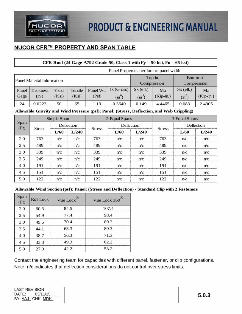
24 0.0222 50 65 1.19 0.3640 0.149 4.4465 0.083 2.4905
Allowable Gravity and Wind Pressure (psf): Panel: (Stress, Deflection, and Web Crippling)
Simple Span 2 Equal Spans 3 Equal Spans
Deflection Deflection Deflection
L/60 L/240 L/60 L/240 L/60 L/240
2.0 763 n/c n/c 763 n/c n/c 763 n/c n/c
2.5 489 n/c n/c 489 n/c n/c 489 n/c n/c
3.0 339 n/c n/c 339 n/c n/c 339 n/c n/c
3.5 249 n/c n/c 249 n/c n/c 249 n/c n/c
4.0 191 n/c n/c 191 n/c n/c 191 n/c n/c
4.5 151 n/c n/c 151 n/c n/c 151 n/c n/c
5.0 122 n/c n/c 122 n/c n/c 122 n/c n/c
Allowable Wind Suction (psf): Panel: (Stress and Deflection) - Standard Clip with 2 Fasteners
Span
(Ft)Roll Lock Vise Lock
Vise Lock 360
2.0 60.3
2.5 54.9
3.0 49.5
3.5 44.1
4.0 38.7
4.5 33.3
5.0 27.9
Ma
(Kip-in.)
Span
(Ft) Stress Stress Stress
CFR Roof (24 Gage A792 Grade 50, Class 1 with Fy = 50 ksi, Fu = 65 ksi)
Top in
Compression
Bottom in
Compression
Panel
Gage
Thickness
(in.)
Yield
(Ksi)
Tensile
(Ksi)
Panel Wt.
(Psf)
Ix (Gross)
(in4)
Sx (eff.)
(in3)
Ma
(Kip-in.)
Sx (eff.)
(in3)
49.3
42.2
107.4
98.4
89.3
80.3
71.3
62.2
53.2
84.5
77.4
70.4
63.3
56.3
Contact the engineering team for capacities with different panel, fastener, or clip configurations.
Note: n/c indicates that deflection considerations do not control over stress limits.
LAST REVISION DATE: 02/16/15 BY: AK CHK: EGB
DETAIL NAME IF APPLICABLE
SSSM0020.DWG 5.0.4
NUCOR CFR TM SEAMING OPTIONS
GENERAL
The Nucor CFRTM roof system has three seam type options. The project design and performance requirements govern which seam type is required.
Different seam types may be required on specific areas of the roof. In all cases, refer to the erection drawings to determine the required seam type and locations.
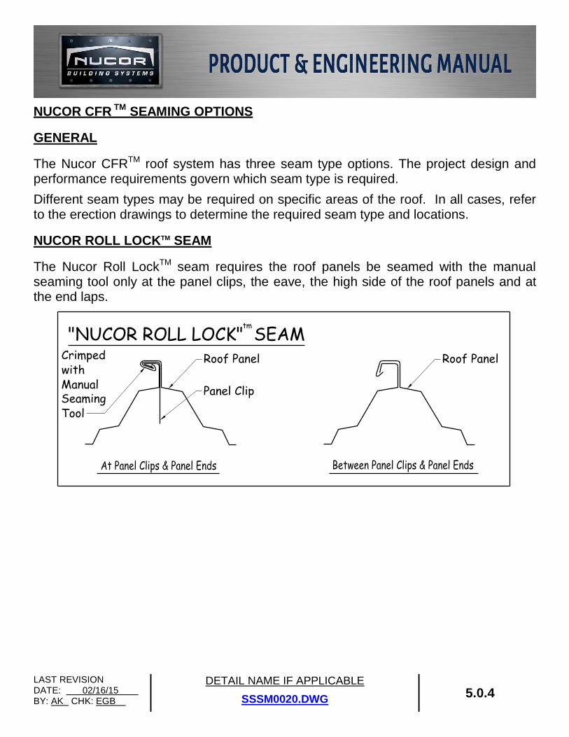
NUCOR ROLL LOCKTM SEAM
The Nucor Roll LockTM seam requires the roof panels be seamed with the manual seaming tool only at the panel clips, the eave, the high side of the roof panels and at the end laps.
Panel Clip
Roof Panel Roof Panel
"NUCOR ROLL LOCK" SEAMCrimpedwithManualSeamingTool
tm
LAST REVISION DATE: 3/28/13 BY: EGB CHK: AES
DETAIL NAME IF APPLICABLE
SSSM0020A.DWG & SSSM0020B.DWG 5.0.5
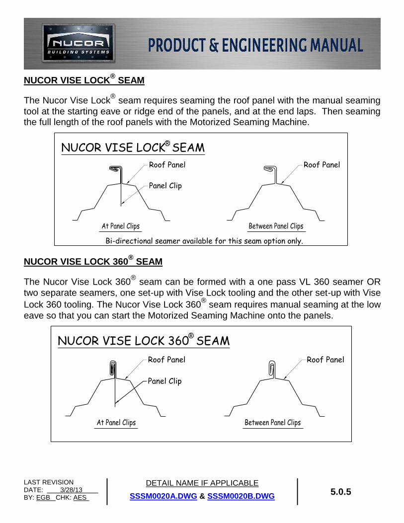
NUCOR VISE LOCK® SEAM
The Nucor Vise Lock® seam requires seaming the roof panel with the manual seaming
tool at the starting eave or ridge end of the panels, and at the end laps. Then seaming the full length of the roof panels with the Motorized Seaming Machine.
NUCOR VISE LOCK 360® SEAM
The Nucor Vise Lock 360®
seam can be formed with a one pass VL 360 seamer OR
two separate seamers, one set-up with Vise Lock tooling and the other set-up with Vise
Lock 360 tooling. The Nucor Vise Lock 360® seam requires manual seaming at the low
eave so that you can start the Motorized Seaming Machine onto the panels.
Panel Clip
Roof Panel Roof Panel
NUCOR VISE LOCK SEAM
Bi-directional seamer available for this seam option only.
R
Roof Panel Roof Panel
Panel Clip
NUCOR VISE LOCK 360 SEAMR
LAST REVISION DATE: 02/06/15 BY: KMC CHK: EGB
DETAIL NAME IF APPLICABLE
CF0025PE.DWG 5.0.6
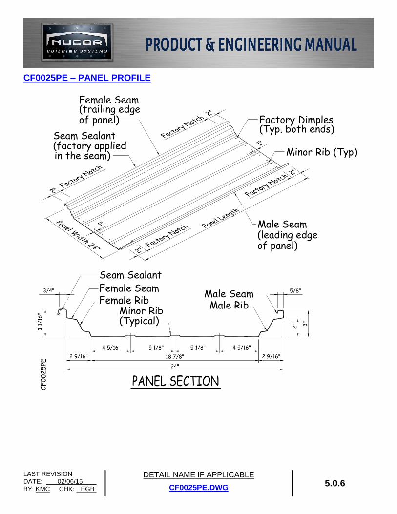
CF0025PE – PANEL PROFILE
Female SeamMale Seam
Factory Dimples
Seam Sealant(factory applied
Male RibFemale Rib
in the seam)
Female Seam(trailing edgeof panel)
5/8"3/4"
Seam Sealant
3"
2"
24"
18 7/8" 2 9/16"2 9/16"
3 1
/16
"
of panel)(leading edgeMale Seam
(Typ. both ends)
Minor Rib (Typ)
5 1/8"4 5/16" 5 1/8" 4 5/16"
Minor Rib(Typical)
CF
00
25
PE
LAST REVISION DATE: 12/29/17 BY: EGB CHK: KMC
DETAIL NAME IF APPLICABLE
CF0010PE.DWG 5.0.7
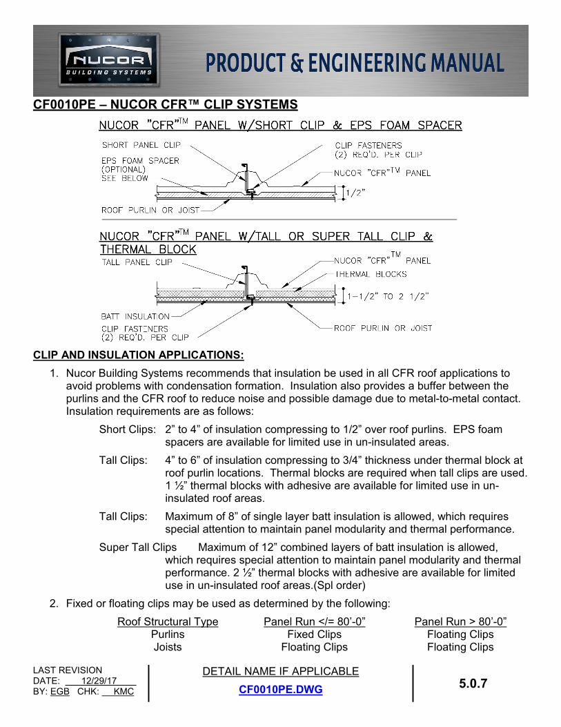
CF0010PE – NUCOR CFR™ CLIP SYSTEMS
CLIP AND INSULATION APPLICATIONS:
1. Nucor Building Systems recommends that insulation be used in all CFR roof applications to avoid problems with condensation formation. Insulation also provides a buffer between the purlins and the CFR roof to reduce noise and possible damage due to metal-to-metal contact. Insulation requirements are as follows:
Short Clips: 2” to 4” of insulation compressing to 1/2” over roof purlins. EPS foam spacers are available for limited use in un-insulated areas.
Tall Clips: 4” to 6” of insulation compressing to 3/4” thickness under thermal block at roof purlin locations. Thermal blocks are required when tall clips are used. 1 ½” thermal blocks with adhesive are available for limited use in un-insulated roof areas.
Tall Clips: Maximum of 8” of single layer batt insulation is allowed, which requires special attention to maintain panel modularity and thermal performance.
Super Tall Clips Maximum of 12” combined layers of batt insulation is allowed, which requires special attention to maintain panel modularity and thermal performance. 2 ½” thermal blocks with adhesive are available for limited use in un-insulated roof areas.(Spl order)
2. Fixed or floating clips may be used as determined by the following:
Roof Structural Type Panel Run </= 80’-0” Panel Run > 80’-0” Purlins Joists
Fixed Clips Floating Clips
Floating Clips Floating Clips
LAST REVISION DATE: 12/29/17 BY: EGB CHK: KMC
DETAIL NAME IF APPLICABLE
EA6022.DWG 5.0.8
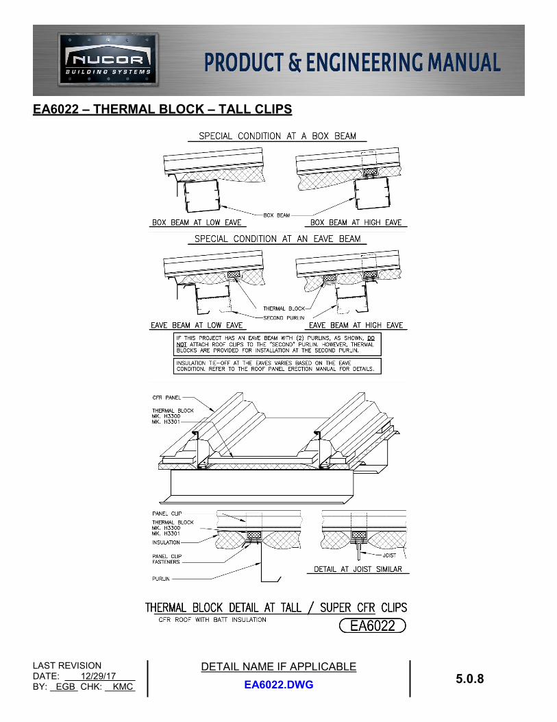
EA6022 – THERMAL BLOCK – TALL CLIPS
LAST REVISION DATE: 12/29/17 BY: EGB CHK: KMC
DETAIL NAME IF APPLICABLE
EA6023.DWG 5.0.9
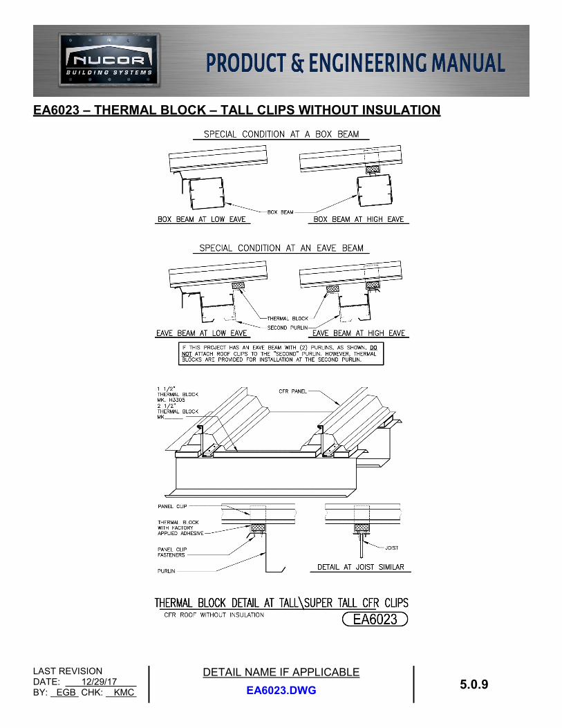
EA6023 – THERMAL BLOCK – TALL CLIPS WITHOUT INSULATION
LAST REVISION DATE: 02/16/15 BY: AK CHK: EGB
DETAIL NAME IF APPLICABLE
EA6024.DWG 5.0.10
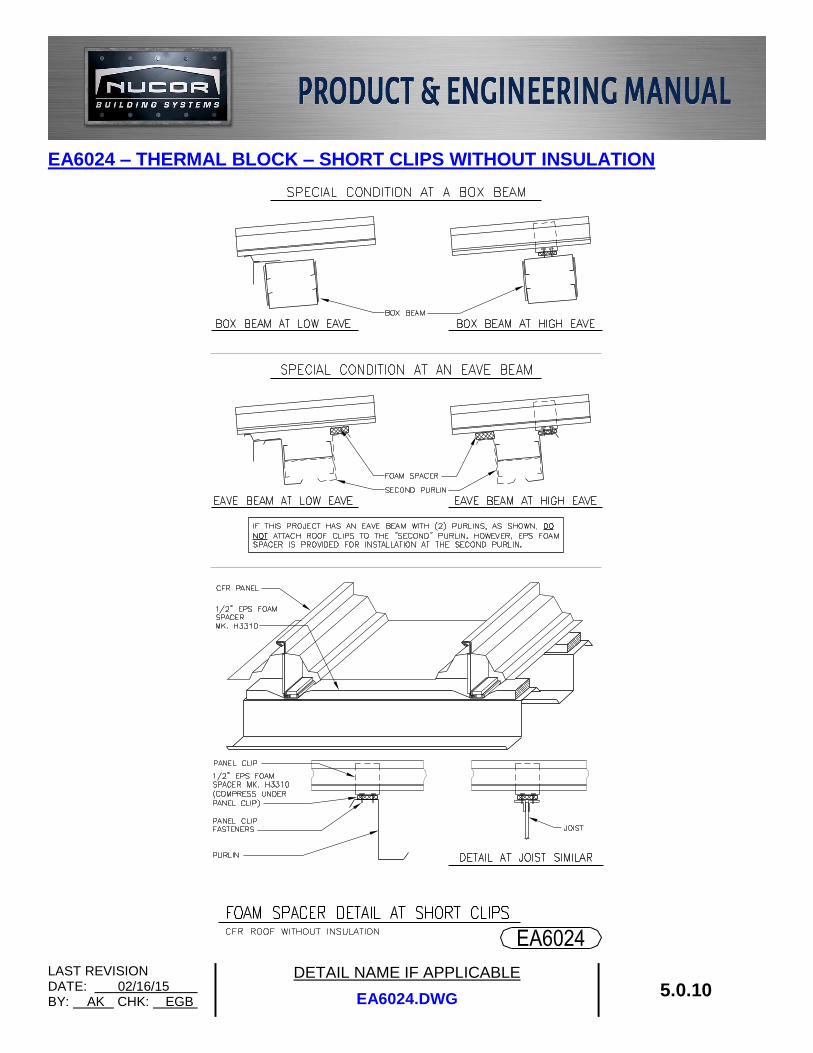
EA6024 – THERMAL BLOCK – SHORT CLIPS WITHOUT INSULATION
LAST REVISION DATE: 12/29/17 BY: EGB CHK: SAA
DETAIL NAME IF APPLICABLE
EA6025.DWG 5.0.11
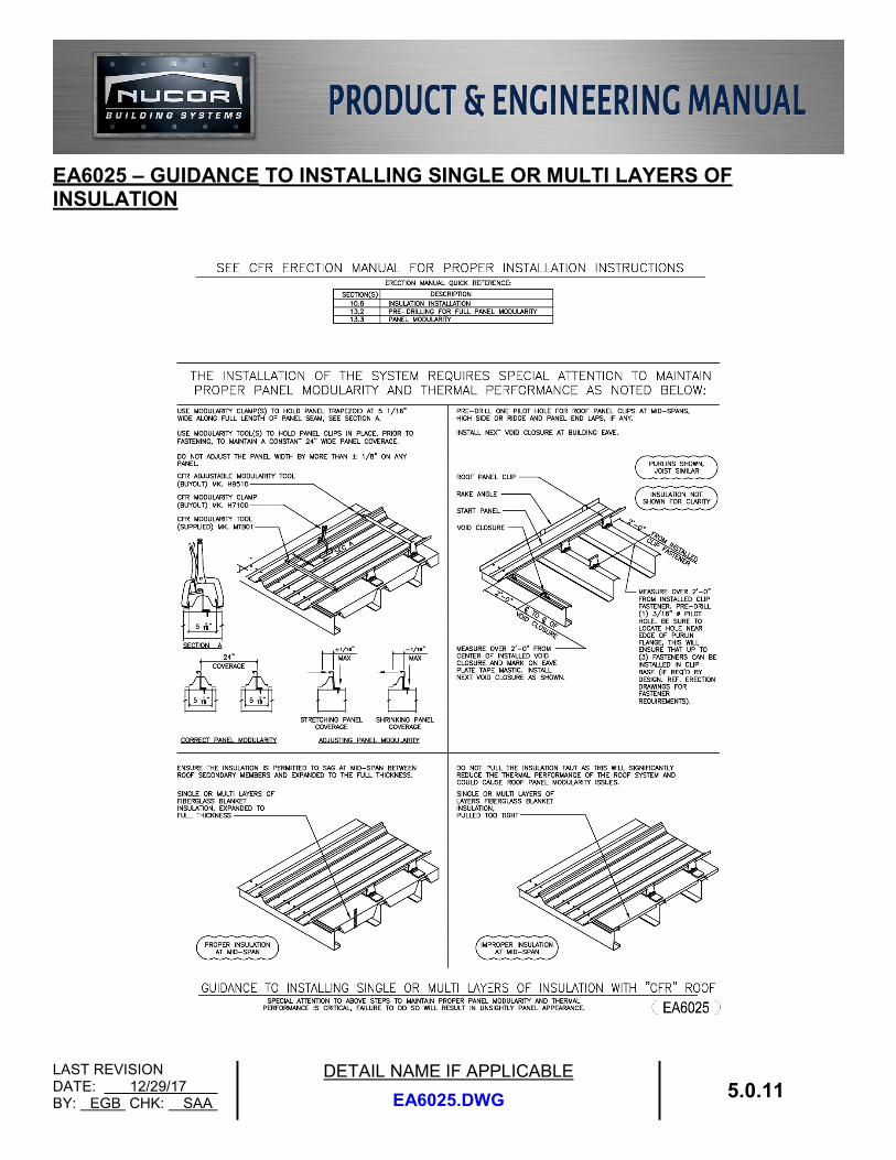
EA6025 – GUIDANCE TO INSTALLING SINGLE OR MULTI LAYERS OF
INSULATION
LAST REVISION DATE: 02/16/15 BY: AK CHK: EGB
DETAIL NAME IF APPLICABLE
FA6003.DWG 5.0.12
NUCOR COMPOSITE CFR™ OPTIONS:
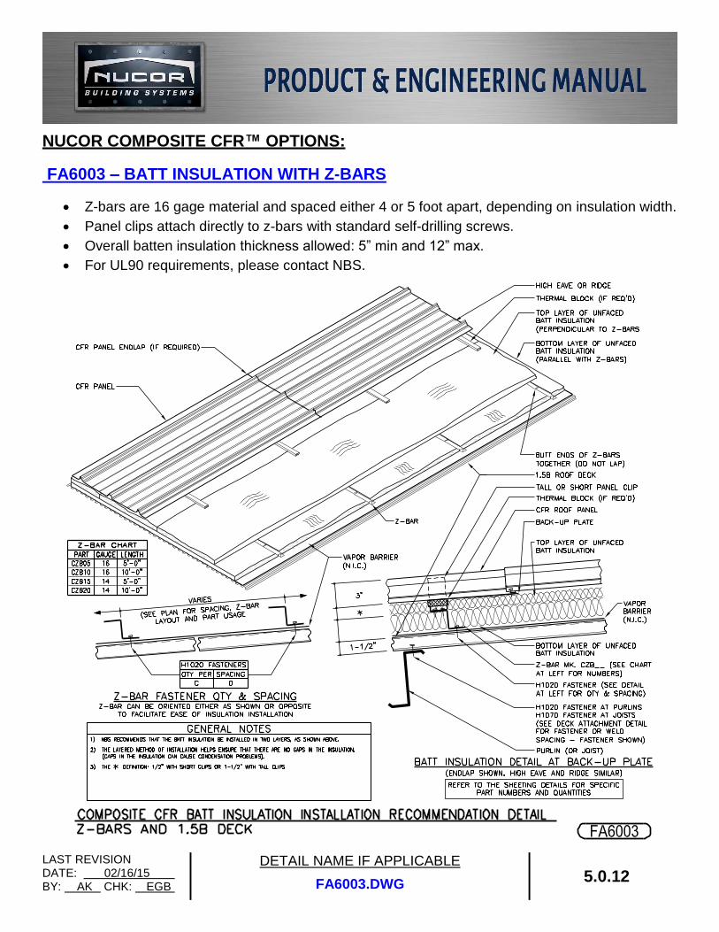
FA6003 – BATT INSULATION WITH Z-BARS
Z-bars are 16 gage material and spaced either 4 or 5 foot apart, depending on insulation width.
Panel clips attach directly to z-bars with standard self-drilling screws.
Overall batten insulation thickness allowed: 5” min and 12” max.
For UL90 requirements, please contact NBS.
LAST REVISION DATE: 02/16/15 BY: AK CHK: EGB
DETAIL NAME IF APPLICABLE
FA6004.DWG 5.0.13
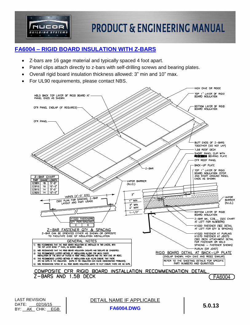
FA6004 – RIGID BOARD INSULATION WITH Z-BARS
Z-bars are 16 gage material and typically spaced 4 foot apart.
Panel clips attach directly to z-bars with self-drilling screws and bearing plates.
Overall rigid board insulation thickness allowed: 3” min and 10” max.
For UL90 requirements, please contact NBS.
LAST REVISION DATE: 02/16/15 BY: AK CHK: EGB
DETAIL NAME IF APPLICABLE
FA6005.DWG 5.0.14
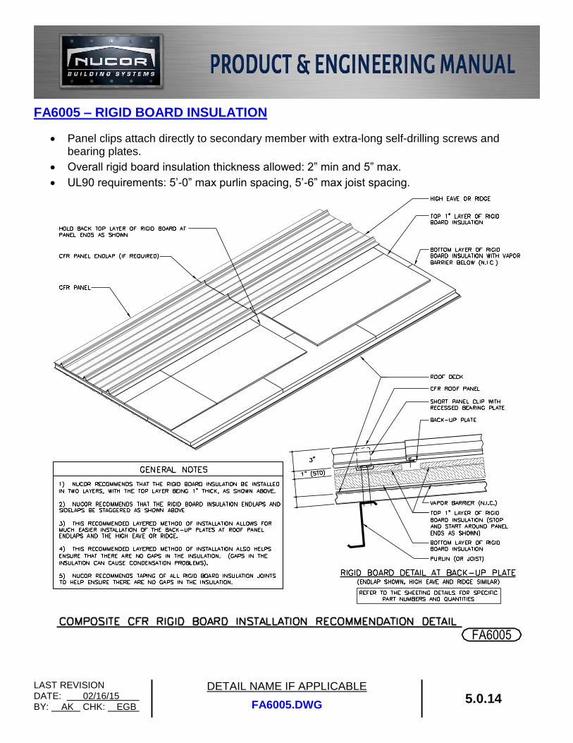
FA6005 – RIGID BOARD INSULATION
Panel clips attach directly to secondary member with extra-long self-drilling screws and bearing plates.
Overall rigid board insulation thickness allowed: 2” min and 5” max.
UL90 requirements: 5’-0” max purlin spacing, 5’-6” max joist spacing.