Embed Size (px)
Citation preview

Scholars' Mine Scholars' Mine
Masters Theses Student Theses and Dissertations
1966
Nucleate-boiling heat transfer to water at atmospheric pressure Nucleate-boiling heat transfer to water at atmospheric pressure
H. D. Chevali
Follow this and additional works at: https://scholarsmine.mst.edu/masters_theses
Part of the Chemical Engineering Commons
Department: Department:
Recommended Citation Recommended Citation Chevali, H. D., "Nucleate-boiling heat transfer to water at atmospheric pressure" (1966). Masters Theses. 2971. https://scholarsmine.mst.edu/masters_theses/2971
This thesis is brought to you by Scholars' Mine, a service of the Missouri S&T Library and Learning Resources. This work is protected by U. S. Copyright Law. Unauthorized use including reproduction for redistribution requires the permission of the copyright holder. For more information, please contact [email protected].
/
NUCLEATE-BOILING HEAT TRANSFER
TO WATER
AT ATMOSPHERIC PRESSURE
BY
H. D . CHEV ALI - 1 &J '-I 0
~~
A
THESIS
submitted to the faculty of
THE UNIVERSITY OF MISSOURI AT ROLLA
in partial fulfi l lment of the requirements for the
Degree of
MASTER OF SCIENCE IN CHEMICAL ENGINEERING
Rol l a, Missouri
1966
Approved by
(Advisor )
ii
ABSTRACT
The purpose of this investigation was to study the hysteresis
effect, the effect of micro-roughness and orientation of the heat-trans
fer surface, and the effect of infra-red-radiation-treated heat-transfer
surfaces on the nucleate-boiling curve.
It has been observed that there exists no hysteresis effect for
water boiling from a cylindrical copper surface in the nucleate-boiling
region over the range studied. The nucleate-boiling curve has been
found to be independent of micro-roughness and orientation of the heat
transfer surface. There was no detectable change in the nucleate-boil
ing characteristics of the heat-transfer surface when the surface was
treated with infra-red radiation.

iii
ACKNOWLEDGEMENTS
The author wishes to express his thanks to Dr. E. L. Park, Jr.
for his suggestions and advice during the course of this investigation.
His help, guidance and encouragements were sincerely appreciated.
The author also expresses his thanks to Mr. v. J. Flanigan for
his help during this investigation. A further word of thanks is extend
ed to Mr. C. B. Cobb who was always willing to listen and offer advice.
The author gratefully acknowledges the equipment provided by the
Mechanical Engineering Department and the Electrical Engineering
Department.
iv
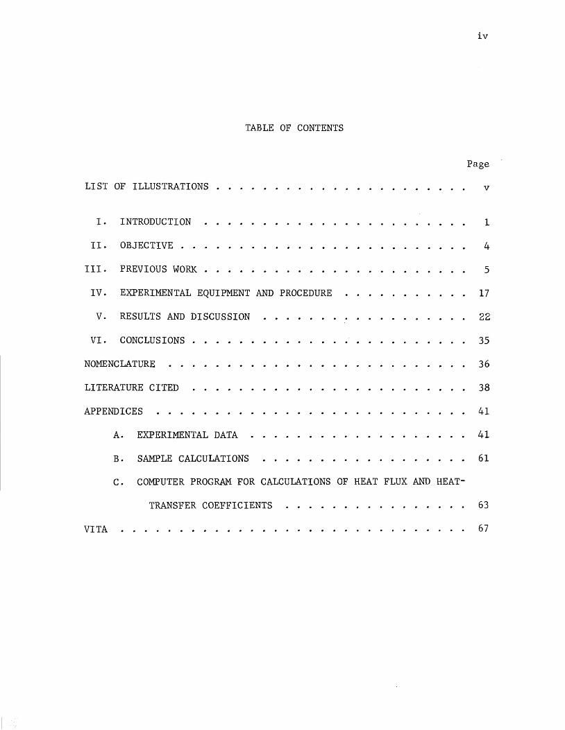
TABLE OF CONTENTS
Page
LIST OF ILLUSTRATIONS . . . . . . . . . . . . . . . . . . . . . . v
I.
II.
III.
IV.
v.
VI.
INTRODUCTION
OBJECTIVE . . .
PREVIOUS WORK .
EXPERIMENTAL EQUIPMENT AND PROCEDURE
RESULTS AND DISCUSSION
CONCLUSIONS
NOMENCLATURE
LITERATURE CITED
APPENDICES
VITA
A.
B.
EXPERIMENTAL DATA
SAMPLE CALCULATIONS
C. COMPUTER PROGRAM FOR CALCULATIONS OF HEAT FLUX AND HEAT-
TRANSFER COEFFICIENTS
1
4
5
17
22
35
36
38
41
41
61
63
67

LIST OF ILLUSTRATIONS
Figure
1. A Typical Boiling Heat-Transfer Curve ...
2.
3.
4.
P-V Diagram from van der Waal's Equation
Heat-Transfer Element . . . . .
Electrical Circuit for the Experiment
Page
2
13
18
21
5. ~T Versus Heat Flux, Orientation Effect for Nucleate Boiling
6.
7.
8.
9.
10.
11.
12.
of Water .
Hysteresis Effect for Nucleate Boiling of Water
Hysteresis Effect for Nucleate Boiling of Water
Roughness Effect for Nucleate Boiling of Water
Effect of Infra-Red Radiation on Nucleate Boiling of Water
Comparison of Data with Previous Data .
Comparison of Data for Various Runs
Flow Sheet for the Computer Program .
24
26
28
29
31
33
34
64

I. INTRODUCTION
The transfer of heat by boiling has become important with the
recent technological developments in the fields of rocket engines and
nuclear reactors, where large quantities of heat are produced in small
spaces. A heat release of about 40,000 Btu/Hr. Cu. Ft. is considered
good practice in a modern boiler; but, in a rocket or a nuclear reac
tor, the heat transfer may be of the order of 108 Btu/Hr. Cu. Ft. (20).
The field of boiling heat transfer was first explored by Nukiyama
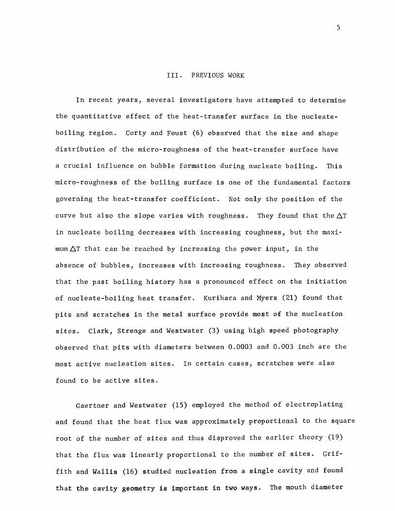
(27) in 1934. It was found that boiling heat transfer could be divided
into four distinct regions according to temperature differences as shown
in Figure 1. The whole process of boiling can best be described by con
sidering a heat-transfer surface submerged in a pool of liquid at satu
ration temperature.
As the surface temperature is raised slightly above the saturation
temperature, heat is transferred to liquid near the heating surface by
free convection (Region I). Convection currents circulate this super
heated liquid, and evaporation takes place at the free surface of the
liquid.
As the temperature difference increases further vapor bubbles form,
rise from the active sites on the heat-transfer surface, but condense
before reaching the free surface of the liquid (Region 2). Within this
region increasing surface temperature leads to more and larger bubbles.
In this region, called the region of nucleate boiling, large heat-trans
fer coefficients are obtained with relatively low temperature driving

CONVECTIVE NUCLEATE UNSTABLE FILM STABLE FILM
I II III IV A
LOG TEMPERATURE DIFFERENCE,~ T
Figure 1. A Typical Boiling Heat-Transfer Curve (29)
3
forces. In the nucleate-boiling region, heat-transfer coefficients of
several thousand Btu/Hr. Ft? °F are not uncommon (29). The peak of the
nucleate-boiling curve, point A, is known as the critical heat flux or
burnout point. Technologically, this is the most important point on
the entire boiling curve (29).
If the surface temperature is increased beyond the burnout point,
an unstable film of vapor forms on the heat-transfer surface (Region III).
This vapor film collapses and forms repeatedly under the action of cir
culating currents. The thermal resistance of this film causes a reduc
tion in heat flux and the heat-transfer coefficient may drop by a factor
of one hundred or more (5). Point B is known as the minimum film-boil
ing point.
Stable film boiling (Region IV) is eventually encountered with
further increase in temperature. The vapor film is very stable and is
continuous over the entire heating surface. The bubble formation is
controlled by factors operating at the outer surface of the film, so
that the heat-transfer surface has little effect on the heat-transfer
rate. The surface temperature required to maintain stable film boiling
is very high and once this condition is attained, a significant portion
of the heat lost by the surface may be the result of thermal radiation
(18).
4
II. OBJECTIVE
In this investigation, nucleate-boiling heat transfer to water
from a cylindrical copper surface at atmospheric pressure was studied.
An attempt was made to observe the effect of micro-roughness and orien
tation of the heating element on the boiling curve. The effect of
treating the heat-transfer surface with infra-red radiation was stud
ied. An attempt was made to determine whether hysteresis was important
in the nucleate-boiling region for water.
5
III. PREVIOUS WORK
In recent years, several investigators have attempted to determine
the quantitative effect of the heat-transfer surface in the nucleate
boiling region. Corty and Foust (6) observed that the size and shape
distribution of the micro-roughness of the heat-transfer surface have
a crucial influence on bubble formation during nucleate boiling. This
micro-roughness of the boiling surface is one of the fundamental factors
governing the heat-transfer coefficient. Not only the position of the
curve but also the slope varies with roughness. They found that the~T
in nucleate boiling decreases with increasing roughness, but the maxi
mum~T that can be reached by increasing the power input, in the
absence of bubbles, increases with increasing roughness. They observed
that the past boiling history has a pronounced effect on the initiation
of nucleate-boiling heat transfer. Kurihara and Myers (21) found that
pits and scratches in the metal surface provide most of the nucleation
sites. Clark, Strenge and Westwater (3) using high speed photography
observed that pits with diameters between 0.0003 and 0.003 inch are the
most active nucleation sites. In certain cases, scratches were also
found to be active sites.
Gaertner and Westwater (15) employed the method of electroplating
and found that the heat flux was approximately proportional to the square
root of the number of sites and thus disproved the earlier theory (19)
that the flux was linearly proportional to the number of sites. Grif
fith and Wallis (16) studied nucleation from a single cavity and found
that the cavity geometry is important in two ways. The mouth diameter

6
determines the superheat needed to initiate boiling and its shape
determines its stability, once boiling has begun. Contact angle is
shown to be important in bubble nucleation primarily through its
effect on cavity stability. Denny (7) investigated the activity of
artificial surface cavities of different geometry in the absence of
naturally occurring nuclei. Cylindrical cavities with depths ranging
from 0.0002 to 0.001 inch were found to be active nuclei. Roll and
Myers (31) made an attempt to explain how surface tension changes are
reflected by changes in delay time, growth time and volume of the
bubble.
Young and Hummel (32) found that the nucleate-boiling heat trans
fer can be improved for the same conditions by applying tetraflouro
ethylene resin (teflon) over the surface.
Ennis (9) found that a greater amount of heat is transferred when
the heat-transfer surface is oscillating. He made an attempt to explain
this phenomena in terms of a thinning effect on the heat-transfer film
around the surface.
Due to limited observations and information, the exact mechanism
of nucleate boiling is not yet definitely established. There have been
several mechanisms proposed to explain nucleate boiling but only four
of them are widely known. These are described briefly.
Micro-Convection in Sublayer:
It is assumed that the large convective currents which are caused
by growth and collapse of bubbles are responsible for high heat flux in

7
the superheated sublayer of liquid. If this mechanism were correct,
the heat flux should strongly depend on the temperature difference
(Twall - Tliquid) which is the driving potential for the heat flux.
Forster and Greif (11) pointed out that, for the same superheat (Twall -
Tsat.), the heat flux in nucleate boiling remains essentially unaffected
while the subcooling may increase by a factor of ten and (Twall - Tliquid)
may increase by a factor of three.
Latent Heat Transport by Bubbles:
Latent heat transport means that during the time a bubble grows it
absorbs latent heat of vaporization which is then returned to the liquid
bulk when the bubble collapses. Jakob (19) showed that this hypothesis
accounts for only a very small fraction of total heat flux.
Vapor-Liquid Exchange Action:
This mechanism suggested by Forster and Greif (11), postulates that
the amount of heat transferred by liquid-vapor exchange taking place
every time a bubble grows and then collapses on or detaches from the
heating surface is by itself sufficient to account for the high rates
of heat transfer.
Mass Transfer Through the Bubbles:
Moore and Mesler (26) observed that the surface temperature of a
nucleation site drops 20 to 30°F in about 2 milliseconds during nucleate
boiling. They explained this phenomena by assuming that as the bubble
grows on the surface the interior of the bubble is exposed to a micro-
8
layer of liquid which wets the surface. This microlayer of liquid vapor-
izes quickly and condenses on the top of the bubble, giving up its latent
heat of vaporization. A quick drop in the surface temperature is
explained by the rapid removal of heat due to the vaporization.
These four mechanisms are widely discussed in literature by vari-
ous authors. Possibly none of these mechanisms is correct and there
exists an entirely different mechanism. It is also possible that the
combination of two or more of these and/or other unknown mechanisms
may be taking place simultaneously.
Correlations:
Several correlations have been proposed for the nucleate-boiling
heat transfer; however, none of these correlations are in agreement with
all the available data. In certain casesJ they are in error by a hun-
dred percent or more. The lack of agreement in the correlations is not
at all unexpected because of incomplete knowledge of the mechanism and
failure to include surface effects in the correlations.
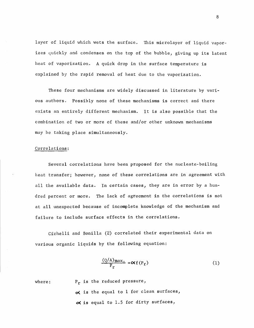
Cfchelli and Bonilla (2) correlated their experimental data on
various organic liquids by the following equation:
where:
(Q/A)max. =o<f(Pr) Pr
Pr is the reduced pressure,
o( is the equal to 1 for clean surfaces,
o( is equal to 1.5 for dirty surfaces,
(1)

9
(Q/A)max. is the heat flux at the burnout point.
Zuber (33) assumed that the large heat-transfer rates associated
with nucleate boiling are a consequence of the micro-convection in the
superheated sublayer and derived the following equation:
(2)
where: L is the latent heat of vaporization, Btu/Lbm,
e is the density, Lbm/Ft3,
C(is the surface tension, Lbf/Ft.
Forster and Greif (11), assuming a mechanism of vapor-liquid ex-
change action derived the following equation:
where: cP is the specific heat at constant pressure,
J is the mechanical equivalent of heat,
k is the thermal conductivity,
L is the latent heat of vaporization,
Ts is the saturation temperature,
~p is the pressure difference corresponding to superheat,
0( is the thermal diffusivity,
el is the density of the liquid,
ev is the density of the vapor,
..u is the viscosity
(!' is the surface tension,
Q/A is the heat flux.
10
It should be noted that equation 3 is valid only for the following
liquids under the following given restrictions:
Water - for pressure from 1 to 50 atmosphere.
n-butyl alcohol - for 50 psia only.
Aniline - for 35 psia only.
Mercury - for 1 and 3 atmospheres only.
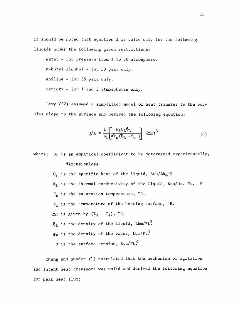
Levy (22) assumed a simplified model of heat transfer to the bub-
bles close to the surface and derived the following equation:
(4)
where: B1 is an empirical coefficient to be determined experimentally,
dimensionless.
c1 is the specific heat of the liquid, Btu/Lbm°F
K1 is the thermal conductivity of the liquid, Btu/Hr. Ft. °F
Ts is the saturation temperature, 0 R.
Tw is the temperature of the heating surface, 0 R.
~T is given by (Tw - Ts), 0 R.
eL is the density of the liquid, Lbm/Ft~
ev is the density of the vapor, Lbm/Ft~
~is the surface tension, Btu/Ft?
Chang and Snyder (1) postulated that the mechanism of agitation
and latent heat transport was valid and derived the following equation
for peak heat flux:

11
(~) (5) max.
where: C takes values between 0.25 and 0.5 depending upon how the
liquid contacts the heating surface.
Cp = specific heat capacity of liquid.
K1 = thermal conductivity of liquid.
Ts = saturation temperature.
~p = pressure difference corresponding to the superheat.
eo = superheat.
'A= latent heat of vaporization.
el = density of liquid.
~v = density of vapor.
~= surface tension.
T. Hara (17) obtained the following empirical relation to calculate
heat transfer near nucleation sites:
(6)
where: _69 is the temperature difference between the heating surface
and saturation temperature.
n is the number of nucleation sites.
q is the average heat flux.
Recently, it has been postulated that the critical heat flux is a
function of the thermodynamic properties of the fluid and of the surface
geometry. Surface geometry can be eliminated for the liquids boiling
on the same surface. Thus, it is possible to Obtain a correlation in
12
terms of reduced properties for liquids that follow the theory of
corresponding states and that are boiling on the same surface.
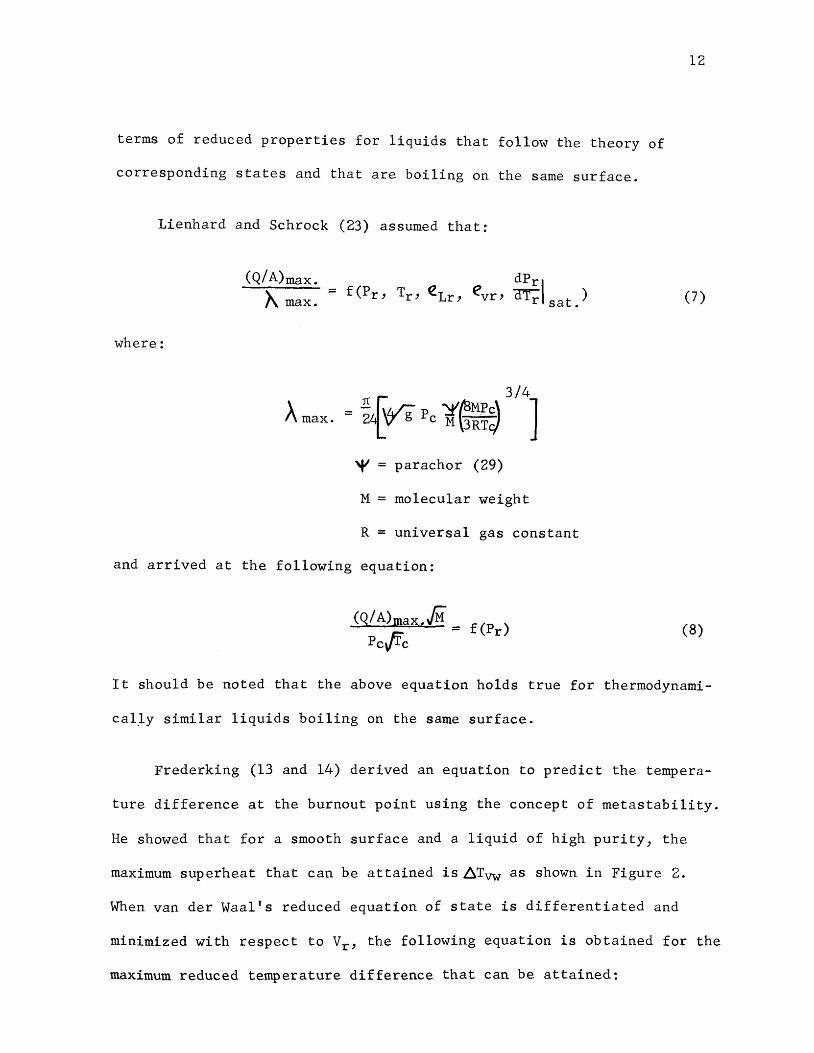
Lienhard and Schrock (23) assumed that:
(Q/A)max.
'1\ max. = (7)
where:
A max.
3/4 = 1£ I htJg p y{BMP£\ ]
2tV o c M \JRTc/
~ parachor (29)
M = molecular weight
R = universal gas constant
and arrived at the following equation:
(Q/ A)max./M. = f (Pr)
Pc./fc (8)
It should be noted that the above equation holds true for thermodynami-
cal_ly similar liquids boiling on the same surface.
Frederking (13 and 14) derived an equation to predict the tempera-
ture difference at the burnout point using the concept of metastability.
He showed that for a smooth surface and a liquid of high purity, the
maximum superheat that can be attained is~Tvw as shown in Figure 2.
When van der Waal's reduced equation of state is differentiated and
minimized with respect to Vr, the following equation is obtained for the
maximum reduced temperature difference that can be attained:
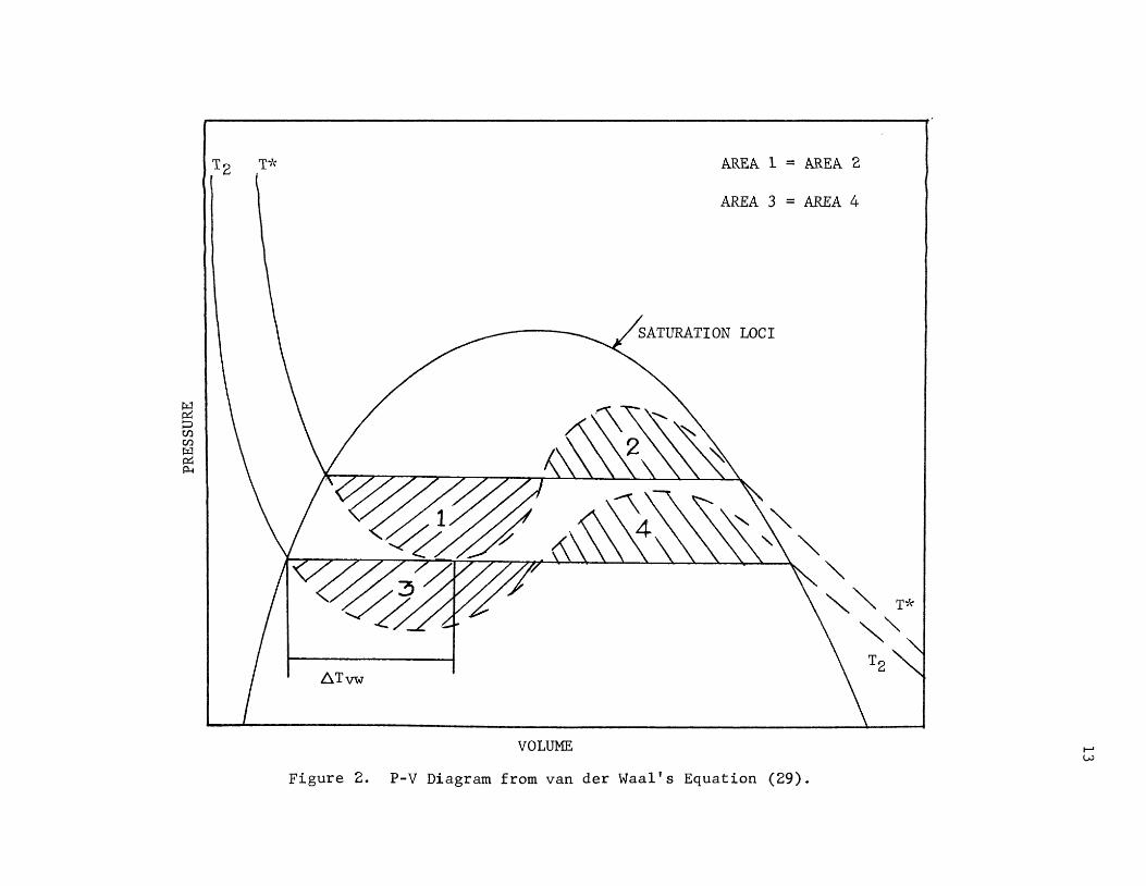
AREA 1 = AREA 2
AREA 3 = AREA 4
6.Tvw
VOLUME
Figure 2. P-V Diagram from van der Waal's Equation (29).
- 6.Tvw ~Tr- -- = Tc
•k Tr - Tr sat.
He defined the degree of metastability as:
E ~bo = 6Tvw =
Temperature difference in actual system Theoretical temperature difference
14
(9)
(10)
Since the effect of several possible important variables is not
understood, no general equation has been established to predict the heat
flux at the burnout point. For liquids which follow the theory of cor-
responding states, Park (29) developed a method that eliminates several
variables which affect the maximum temperature difference in the nucleate-
boiling region. The degree of metastability is assumed to be a function
of heat-transfer-surface geometry, number of potentially active sites
and the reduced temperature.
(11)
where ~ is the geometric factor and N is number of potentially active
sites. If the above equation is valid, E should be the same for all
liquids that follow the theory of corresponding states boiling on the
same heat-transfer surface.
The effect of surface conditions and surface geometry is then
eliminated by setting a reference value of E for each surface and divid-
ing all the f's by this reference value.
This excellent analysis yielded the following equation:
15
6Tbo ref. (12)
It should be noted that the above equation holds true for all the
liquids that follow the theory of corresponding states boiling on any
heat-transfer surface with the possible exception of thin wires.
Cobb and Park (5) extended the above work to predict the heat flux
at the burnout point using a similar procedure. They assumed that the
heat flux is a function of surface geometry, number of potentially
active sites and heat of vaporization.
(Q/A)max. = f'(CI>, N,~Hvap.) (13)
where ~Hvap. is heat of vaporization and is obtained from the Clausius
-Clapeyron equation.
Introducing reduced variables in the above equation yields:
~Hvap. = PcVcTr.AVr (dPr) dTr
combining equations 14 and 15 yields:
(14)
(15)
(16)
The effects of surface geometry and surface conditions are then elimin-
ated by setting a reference value of (Q/A)max. for each surface and
dividing all the value of (Q/A) by the reference value. max.
16
This analysis yielded:
[~(Q/~A)~mal..oQo,..&.,x --]= ftT. r~vr(~) (Q) A)max. ref. Trt~Nr(dPr 'f
dTrJiref.
(17)
It should be noted that the above equation holds true for the liq-
uids that follow the theory of corresponding states. It requires one
burnout heat flux to be known. It can be used for comparison of maxi-
mum heat fluxes obtained under different experimental conditions. The
greatest advantage of this method is that it permits the prediction of
high pressure heat fluxes from atmospheric data.
17
IV. EXPERIMENTAL EQUIPMENT AND PROCEDURE
The experimental equipment consisted of a heat-transfer element,
a power source} a variable resistance, a wattmeter, and a d.c. null
voltmeter.
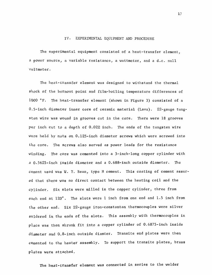
The heat-transfer element was designed to withstand the thermal
shock of the burnout point and film-boiling temperature differences of
1000 °F. The heat-transfer element (shown in Figure 3) consisted of a
0.5-inch diameter inner core of ceramic material (Lava). 22-gauge tung
sten wire was wound in grooves cut in the core. There were 18 grooves
per inch cut to a depth of 0.022 inch. The ends of the tungsten wire
~ere held by nuts on 0.125-inch diameter screws which were screwed into
the core. The screws also served as power leads for the resistance
~inding. The core was cemented into a 3-inch-long copper cylinder with
a 0.5625-inch inside diameter and a 0.688-inch outside diameter. The
cement used was W. T. Bean, type H cement. This coating of cement assur
ed that there was no direct contact between the heating coil and the
cylinder. Six slots ~ere milled in the copper cylinder, three from
each end at 120°. The slots were 1 inch from one end and 1.5 inch from
the other end. Six 22-gauge iron-constantan thermocouples were silver
soldered in the ends of the slots. This assembly with thermocouples in
place was then shrunk fit into a copper cylinder of 0.6875-inch inside
diameter and 0.8-inch outside diamter. Transite end plates were then
cemented to the heater assembly. To support the transite plates, brass
plates were attached.
The heat-transfer element was connected in series to the welder

7 6 &
1. Thermocouple Leads
2. Outer Copper Cylinder
3. Inner Copper Cylinder
4. Tungsten Windings
5. Inner Core of Lava Figure 3. Heat-Transfer Element (28).
6. Transite End Plates
7. Brass End Plate
8. Cement

used as a power source. The welder was rated at 38/19 amperes and
220/440 volts. Also connected in series with the heater was a load
box to control and vary the power input.
The energy supplied was measured by means of a wattmeter. The
wattmeter used was type P3 and was rated at a maximum of 1 KW. It
was correct to within 0.4% of the full-scale reading.
The temperature was measured by means of a 419 type d.c. null
voltmeter which had an accuracy of ± 2% of the end scale used. The
scales used were 1 and 3 millivolts.
Procedure:
19
For each set of conditions of the surface, several runs were made
to check the reproducibility of the data. The first three runs were
conducted to study nucleate-boiling heat transfer to liquid nitro-
gen from cylindrical copper surfaces at atmospheric pressure. Between
the runs, the heat-transfer element was kept in a nitrogen atmosphere.
In the rest of the investigation, nucleate-boiling heat transfer to
water from cylindrical copper surfaces at atmospheric pressure was stud
ied. After each run, the heat-transfer element was allowed to come to
room conditions; this procedure apparently did not affect the surface
of the heat-transfer element.
The burnout point was not reached in the runs using water because
of inadequate power. When the maximum available power was supplied,
the bubbles were large and it appeared that the vapor layer was about
to form. The large bubbles indicated that the burnout flux was closely
20
approached.
Several runs were conducted with the heat-transfer surface in the
horizontal position, inclined at 45° and in the vertical position. ~e
surface was then roughened using abrasive cloth. Several runs were
conducted to observe any hysteresis effect, the power was initially
increased to maximum and was then decreased.
The last six runs were conducted to observe the effect of infra
red radiation on the heat-transfer surface. The heat-transfer surface
was exposed to infra-red· radiation for two hours and five hours before
the runs were taken.
At the end of the investigation, the thermocouples were calibrated
and were found to be correct within experimental accuracy (± 0.76°F).
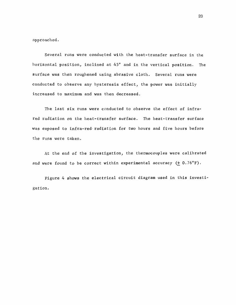
Figure 4 shows the electrical circuit diagram used in this investi
gation.

· WATTMETER LOAD BOX
HEATER J I
~----~-~--~~ J~_.------~
WELDER
D.C. NULL VOLTMETER
Figure 4. Electrical Circuit for the Experiment.
N ,.....

22
V. RESULTS AND DISCUSSION
Most investigators conducting research in nucleate-boiling heat
transfer have represented their data as a plot of the logarithm of tem
perature difference versus the logarithm of heat flux, implying a power
functionality. Admittedly, this method of graphing is convenient; but,
it has a great tendency to mask the scatter of the data. Park (39)
suggested that the data could be better represented as a plot of the
temperature difference versus the heat flux. This method is adopted
to present the data of this investigation. It should be noted that
there is a 10 to 15% inherent error in nucleate-boiling data. The fol
lowing analysis is based on this fact.
The first three runs were conducted to study the nucleate-boiling
heat transfer to liquid nitrogen from a cylindrical copper surface at
atmospheric pressure. The surface ends were sealed using epoxy resin.
The sealed ends were baked for three hours by means of infra-red-heating
lamp. Between the runs, the heat-transfer element was kept in liquid
nitrogen. It is apparent from thermocouple readings that there exists
a radial temperature gradient. This conclusion is in agreement with the
work of previous investigators (10, 28, and 29). An axial temperature
gradient is also observed. Only Parikh (28) has reported such gradient.
These gradients may be due to the difference in contact resistances of
various thermocouples; however, it is likely that the contact resistance
can not totally explain the gradients.
During trial runs on water, it was observed that the epoxy resin
used to seal the heater ends was dissolving in water. In order to
23
prevent this, high temperature, acid-proof cement was used to seal the
ends. It was also observed that the thermocouple readings were highly
erratic because they were short circuited either with the end brass
plates or with the other bare thermocouple wires. The water had an
extreme effect on the iron wires of the thermocouples. Because of cor
rosion all iron wires were corroded and broken. At this stage, a copper
wire was welded to the one end of the heater and thermocouples were
converted into copper-constantan. However, thermocouple 3 was in good
condition and was maintained in its original form of iron-constantan.
Runs 4, 5 and 6 were conducted with the heat-transfer element in
the horizontal position. It was found that at one of the ends the seal
ing was defective. This end was resealed using high temperature, acid
proof cement. It was then treated with acetic acid to assure good
sealing and absolutely no dissolution of cement in boiling water. How
ever, the smooth file used to even the sealing may have changed the
heat-transfer surface to some extent.
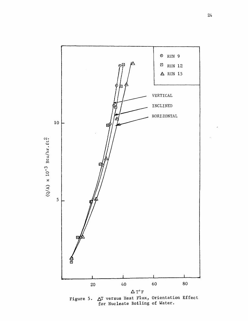
Runs 7 through 15 were taken to study the effect of orientation of
the heat-transfer element on the nucleate-boiling curve. The heat-trans
fer surface was in the vertical position for Runs 7, 8 and 9; 45° posi
tion for Runs 10, 11 and 12 and horizontal position for Runs 13, 14 and
15. Figure 5 shows the comparison of the data of these runs. Only one
run for each orientation is plotted; plotting only one run avoids crowd
ing which would result if data for all the runs were plotted. The data
is reproducible, therefore, one run is representative. Figure 5 clearly
indicates that there exists little variation in the boiling curve when
C\l. -1-J 4-1 . ~
...c: ...........
;::) -1-J t:Q
("t"') I 0 ~
:< ,....... <t! .._ 0' '-"
10
5
20 40
6. T°F
0 RUN 9
El RUN 12
A RUN 15
VERTICAL
INCLINED
HORIZONTAL
60 80
Figure 5. ~T versus Heat Flux, Orientation Effect for Nucleate Boiling of Water.
24
25
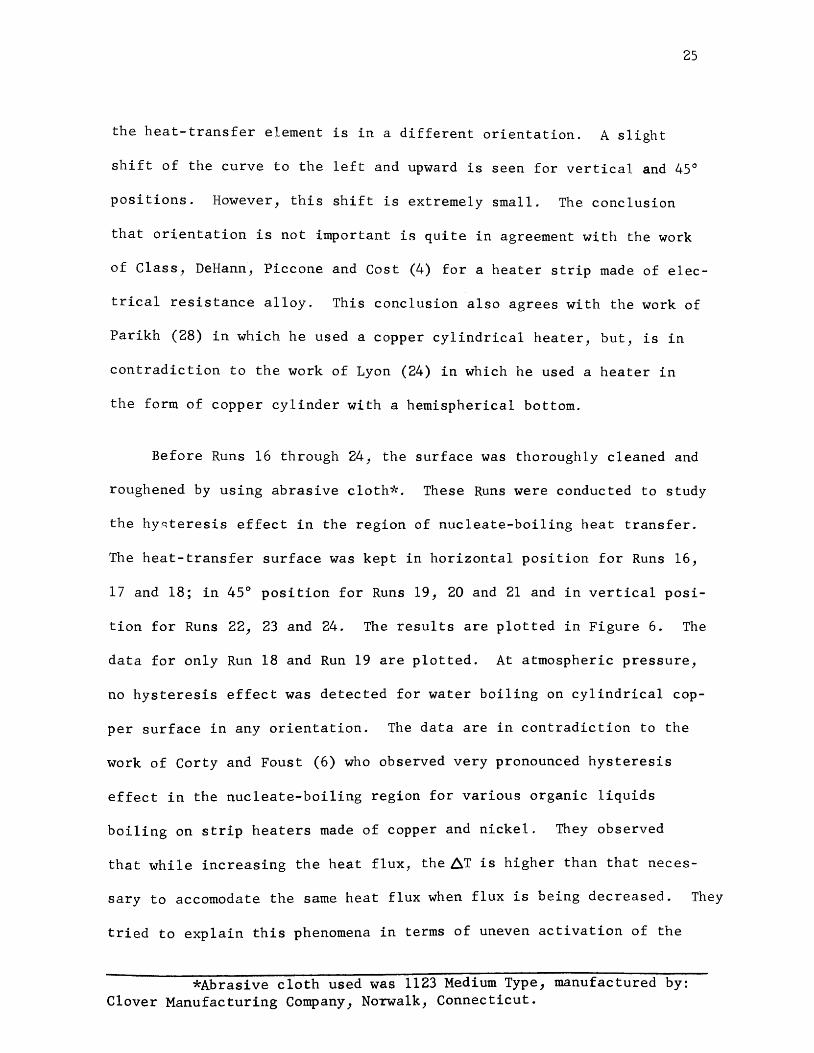
the heat-transfer element is in a different orientation. A slight
shift of the curve to the left and upward is seen for vertical and 45°
positions. However, this shift is extremely small. The conclusion
that orientation is not important is quite in agreement with the work
of Class, DeHann, Piccone and Cost (4) for a heater strip made of elec-
trical resistance alloy. This conclusion also agrees with the work of
Parikh (28) in which he used a copper cylindrical heater, but, is in
contradiction to the work of Lyon (24) in which he used a heater in
the form of copper cylinder with a hemispherical bottom.
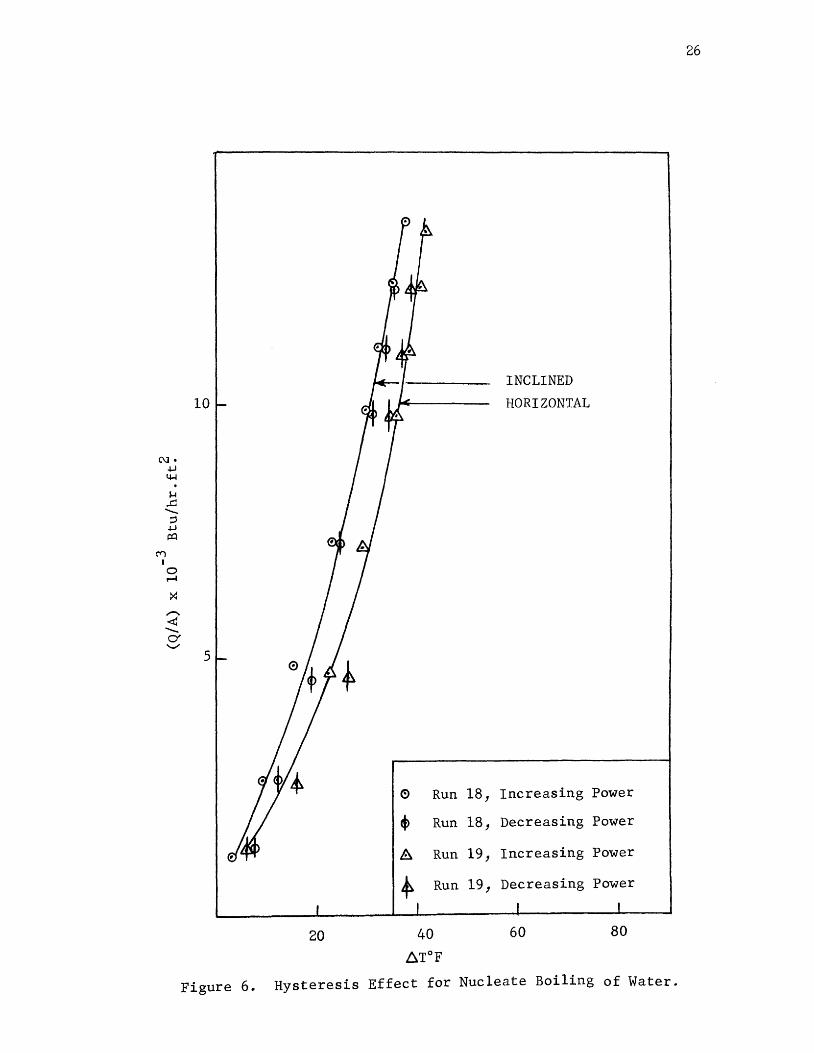
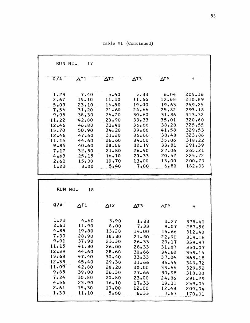
Before Runs 16 through 24, the surface was thoroughly cleaned and
roughened by using abrasive cloth*. These Runs were conducted to study
the hy~teresis effect in the region of nucleate-boiling heat transfer.
The heat-transfer surface was kept in horizontal position for Runs 16,
17 and 18; in 45° position for Runs 19, 20 and 21 and in vertical posi-
tion for Runs 22, 23 and 24. The results are plotted in Figure 6. The
data for only Run 18 and Run 19 are plotted. At atmospheric pressure,
no hysteresis effect was detected for water boiling on cylindrical cop-
per surface in any orientation. The data are in contradiction to the
work of Corty and Foust (6) who observed very pronounced hysteresis
effect in the nucleate-boiling region for various organic liquids
boiling on strip heaters made of copper and nickel. They observed
that while increasing the heat flux, the6T is higher than that neces-
sary to accomodate the same heat flux when flux is being decreased. They
tried to explain this phenomena in terms of uneven activation of the
*Abrasive cloth used was 1123 Medium Type, manufactured by: Clover Manufacturing Company, Norwalk, Connecticut.
N • .j...J
4-l . ~
..c: ..._ ::l
.j...J j:Q
C"'") I 0 r-f
X _,-... <!! ...._ 0' .......,_,
10
5
20
~ Run
40
~T°F
18,
18,
19,
19,
INCLINED
HORIZONTAL
Increasing
Decreasing
Increasing
Decreasing
60
Power
Power
Power
Power
80
Figure 6. Hysteresis Effect for Nucleate Boiling of Water.
26

heat-transfer surface during increase and decrease of the heat flux.
It is possible that the copper heater used in this investigation was
oxidized and there was no change in activation of the heat-transfer
surface. The hysteresis effect observed in the work of Carty and
27
Foust (6) may be due to the nature of the liquids used. They used only
organic liquids which may have decomposed leaving carbon during boiling.
The decomposed carbon may have deposited in cavities which in turn
changed the activation of the heat-transfer surface.
Carty and Foust (6) lowered the flux first and then increased it
slowly. In this work the flux was slowly increased to maximum and was
then decreased. It is interesting to note that during Run 16, the flux
was slowly increased to maximum, then decreased to minimum and was in
creased again to maximum. The results plotted in Figure 7 clearly indi
cate no trace of hysteresis. It is apparent during these runs that the
orientation of the heat-transfer element has no effect on the nucleate
boiling curve.
Runs 4, 5 and 6; Runs 13, 14 and 15 and Runs 16, 17 and 18 were
taken with the heat-transfer element in the horizontal position but with
variations in the surface roughness. Only one run from each group is
plotted on Figure 8. There is only a slight effect from roughness on
the nucleate-boiling curve. This conclusion is quite in agreement with
the work of Lyon (24) and also with the work of Parikh (28). However,
this conclusion is quite contradictory to the results of Carty and Foust
(6) who observed that not only the positions of the boiling curve but al
so the slopes vary a great deal with roughness in the nucleate-boiling
region.

28
RUN 16 ®
0 Increasing Power
A Decreasing Power
13 Reincreasing Powe
10
C\J • .t-1 4-1 . ~
,..c: ....._ :;j
.t-1 ~
("")
I 0 ..-f
~
,-... <t! ....._ 0' "-../
5
20 40 60 80
Figure 7. Hysteresis Effect for Nucleate Boiling of Water.

29
0 RUN 4
EJ RUN 13
A RUN 16
ROUGH SURFACE
C\1 • .w ~ . 1-1
..c ...._ ;:1 .w 1=0
C'i')
I 0 ...-I
X ,....... <G ...._ (Y ""'-../
5
20 40 60 80
Figure 8. Roughness Effect for Nucleate Boiling of Water.

30
The possible explanation is that there exists a certain range of
micro-roughness in which the~T and the slope of the nucleate-boiling
curve are affected by the degree of roughness. The nucleate-boiling
curve would be entirely independent of the roughness outside this
range of micro-roughness.
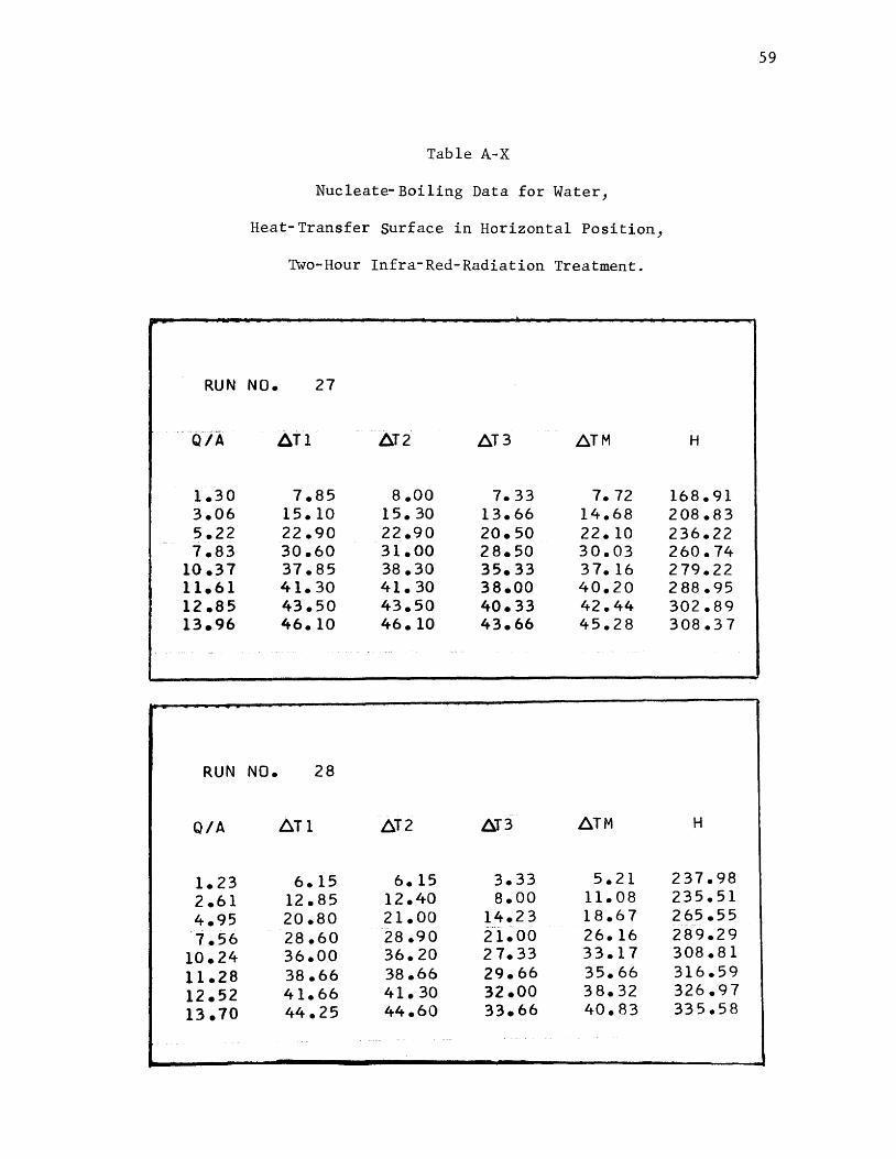
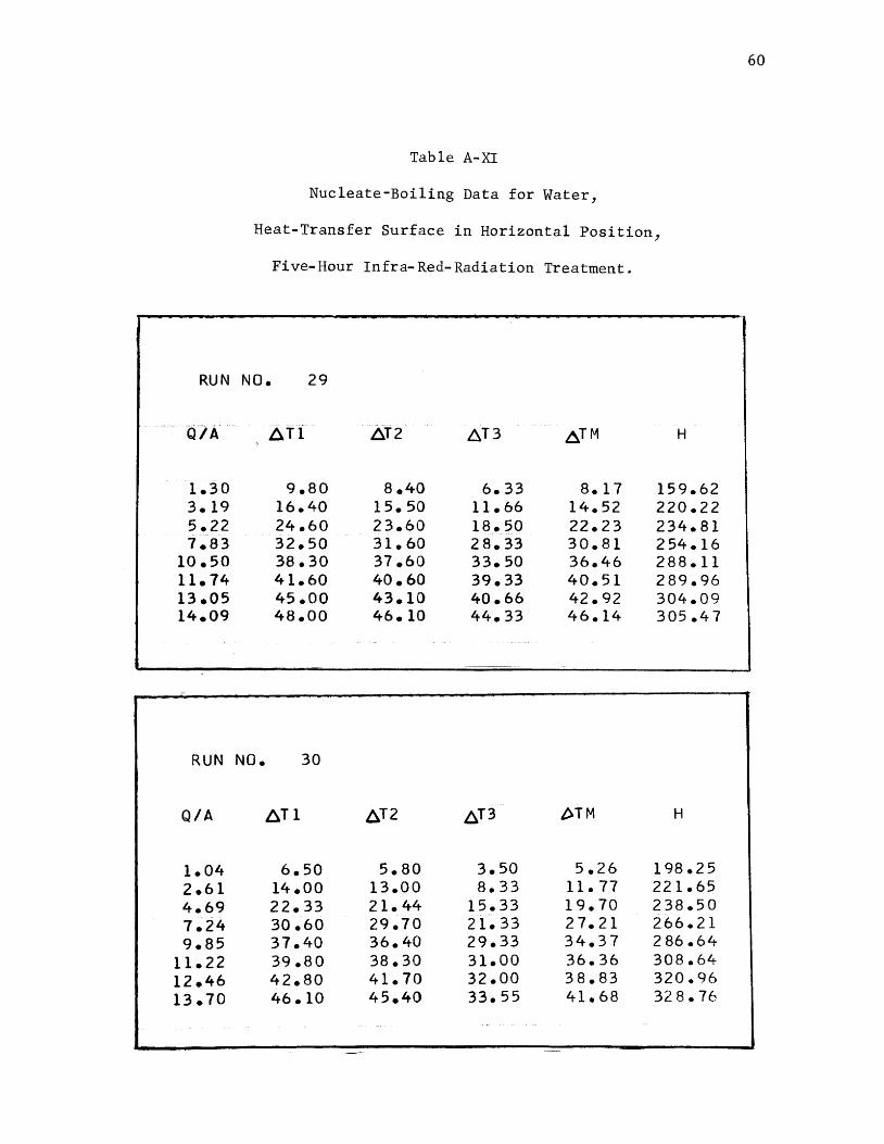
Runs 25 through 30 were taken to study the effect of infra-red
radiation treatment of the heat-transfer surface on the nucleate-boil
ing curve. Runs 25 and 26 were taken on a clean surface. Runs 27 and
28J and Runs 29 and 30 were taken after the heat-transfer surface was
exposed to infra-red radiation for two hours and five hours respectively.
The data of these runs are plotted in Figure 9. The effect from infra
red radiation on the heat-transfer curve in the nucleate-boiling region
was less than the 10% inherent error found in boiling heat-transfer
data. A slight shift to the right and downward was noted for the surface
treated with infra-red radiation. HoweverJ there was no detectable
change in the nucleate-boiling curve for the surface exposed to infra
red radiation for two hours and five hours. Considering the inherent
errorsJ this conclusion is quite contradictory to the work of Parikh (28)
who observed that during nucleate boiling of nitrogen from a copper sur
faceJ the boiling curve shifted to the left and upward indicating a
higher-heat-flux requirement for the same~T. He explained that infra
red radiation caused some surface reaction or surface activation which
caused the curve to shift to the left and upward. The data indicate
that if surface activation did take place by infra-red radiationJ it
remained active in nitrogen but was inactive in water.
During this investigation, various runs were taken to observe the

31
0 RUN 25
A RUN 27
EJ RUN 29
10
C\l• .w 4-1 . 1-1 .c .............
;:l +J 1=0
('t"')
I 0 .....-1
X ,....... <t!
............. (y '-'
5
20 60 80
Figure 9. Effect of Infra-Red Radiation on Nucleate Boiling of Water.
32
effects of orientation, micro-roughness, hysteresis, and infra-red radi
ation on the nucleate-boiling curve for water boiling from copper cylin
drical surfaces at atmospheric pressure. The data of one run from each
representative group is plotted in Figure 11.
Most of the data reported in the literature for nucleate-boiling
heat transfer to water is from a heat-transfer surface which is in a
form of a thin wire. In some cases, the heat-transfer surface used is
a strip heater or a flat plate. No work has been reported with the cy
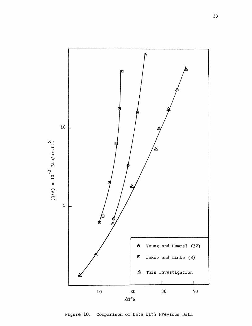
lindrical heat-transfer surface. In Figure 10, a part of the nucleate
boiling data is shown from the work of Young and Hummel (32). They
studied nucleate-boiling heat transfer to water from a strip heater of
stainless steel of the size 5.5 in. x 1.2 in. x 0.01 in. Also shown is
a part of the nucleate-boiling data of Jakob and Linke (8). The heat
transfer surface was a horizontal plate. The data of this investigation
is also plotted in Figure 10.
It should be noted that the nucleate-boiling data of Young and Hum
mel (32) and Jakob and Linke (8) are read from the log-log plots given
in the above references for comparison with the data of this investiga
tion; the complete sets of data are not plotted for the references given
above.
33
0
10
C\J• -1-.1 4-1 . 1-l
..c: .........
;:::l -1-.1 ,:0
('f) I
0 ........
X _,-.... <!:!
......... 0' "-'
5
0 Young and Hunnne1 (32)
8 Jakob and Linke (8)
A This Investigation
10 30 40
Figure 10. Comparison of Data with Previous Data

C\l • ~ 4-1
34
8 0 ·~ ~+
~+
10 r-
5 ~ e RUN 4 A RUN 7 (!) RUN 10
~ RUN 13
-+- RUN 16
? RUN 19
+ RUN 22
0 + RUN 26
• RUN 28
X RUN 30
0
I I I I
10 20 30 40
Figure 11. Comparison of Data for Various .Runs.
VI. CONCLUSIONS
1. The orientation of a cylindrical heat-transfer surface
has little or no effect on the nucleate-boiling curve of water
over the range studied.
2. There exists no hysteresis effect for nucleate-boiling
heat transfer to water from a copper cylindrical surface over the
range studied.
35
3. The micro-roughness of the heat-transfer surface has little
or no effect on the nucleate-boiling curve for water over the range
studied.
4. Infra-red radiation causes little or no effect on the nuc
leate-boiling curve of water over the range studied.
5. There exists radial and axial temperature gradients for cylin
drical surfaces in the nucleate-boiling region.
2 A = Area, ft.
C = Constant in equation 5.
NOMENCLATURE
C H t C •t Btu/lb. °F. p = ea apac1 y,
D = Diameter, ft.
g = Acceleration due to gravity, ft./sec?
2 gc = Conversion factor, lbmft./lbf sec.
H ~ Heat of Vaporization, Btu/lb.
h = Heat-transfer coefficient, Btu/hr.ft? °F.
k = Thermal conductivity, Btu/hr.ft. °F.
L = Latent heat of vaporization, Btu/lb.
M = Molecular weight, lbm/lb.mole.
n = Number of nucleation sites.
P = Pressure, P. S. I.
Q = Rate of heat transfer, Btu/hr.
q = Rate of heat transfer, Btu/hr. ft~
R = Universal gas constant.
T = Temperature, °F.
~T = Temperature difference, (Tsurface - Tliquid), oF.
36
Greek Symbols
() = Surface tension, lb/ft.
A= Heat of vaporization, Btu/lb.
'V = Parachor.
~ = Viscosity, lb/ft. sec.
~ = Geometric factor.
~ = Density, lb/ft~
€ = Degree of metastability.
Subscript
c refers to the critical point.
v refers to the vapor.
L refers to the liquid.
r refers to the reduced property.
vw refers to a substance which behaves as predicted by van der
Waal's equation of state.
37

LITERATURE CITED
1. Chang, Y. and Snyder, N. w., "Heat Transfer in Saturated Boiling Under Pressure," Heat Transfer, c. E. P. Symposium Series, Vol. 56, 1963, P. 25.
38
2. Cichelli, M. T. and Bonnila, C. F., "Heat Transfer to Liquids Boiling Under Pressure," Trans. A. I. Ch. E., Vol. 41, 1945, P. 755.
3. Clark, H. B., Strenge, P. S. and Westwater, J. w., "Active Sites for Nucleate Boiling," Heat Transfer, C. E. P. Symposium Series, Vol. 55, 1959, P. 103.
4. Class, C. R., DeHann, J. R., Piccone, M. and Cost, R. B., "Boiling Heat Transfer to Liquid Hydrogen from Flat Surfaces," Advances in Cryogenic Engineering, Vol. 5, 1960, P. 254.
5. Cobb, C. B. and Park, E. L., Jr., "Correlation of the Maximum Heat Flux and Temperature Difference in the Nucleate Boiling of Corresponding States Liquids," Paper Presented at 1966 Cryogenic Engineering Conference, June, 1966.
6. Carty, C. and Foust, A. s., "Surface Variables in Nucleate Boiling," Heat Transfer, c. E. P. Symposium Series, Vol. 51, 1955, P. 1.
7. Denny, V. E., "Some Effects of Surface Micro-Geometry on Natural Convection and Pool Boiling Heat Transfer to Saturated Carbon Tetrachloride," Ph.D. Thesis, University of Minn., 1961.
8. Eckert, E. R. G. and Drake, M. R., Heat and Mass Transfer, Second Ed., McGraw-Hill Book Company, Inc., New York, 1959.
9. Ennis, B. P., "Boiling Heat Transfer from Oscillating Platinum Wires to Water," Student Member Bulletin, A. I. Ch. E., Spring, 1966, P. 36.
10. Flynn, T. M., Draper, J. w. and Roos, J. J., "The Nucleate and Film Boiling Curve of Liquid Nitrogen at One Atmosphere," Advances in Cryogenic Engineering, Vol. 7, 1962, P. 539.
11. Forster, K. E. and Greif, R., "Heat Transfer to a Boiling Liquid, Mechanism and Correlations," J. Heat Transfer, Vol. 81, 1959, p. 43.
12. Forster, K. E. and Zuber, N., "Dynamics of Vapor Bubbles and Boiling Heat Transfer," A. I. Ch. E. J., Vol. 1, 1955, P. 531.
13. Frederking, T. H. K., Advances in Cryogenic Engineering, Vol. 8, 1963, p. 489.
14. Frederking, T. H. K., As Reported by Park, E. L., Jr., Ph.D. Thesis, University of Oklahoma, 1965.

39
15. Gaertner, R. F. and Westwater, J. W., "Population of Active Sites in Nucleate Boiling Heat Transfer," Heat Transfer, c. E. P. Symposium Series, Vol. 56, 1960, P. 39.
16. Griffith, P. J. and Wallis, J. D., "The Role of Surface Conditions in Nucleate Boiling," Heat Transfer, C. E. P. Symposium Series, Vol. 56, 1960, P. 49.
17. Hara, T., As Reported by Parikh, S. R., M. S. Thesis, University of Missouri at Rolla, 1966.
18. Holman, J. P., Heat Transfer, McGraw-Hill Book Company, Inc., 1963.
19. Jakob, M., Heat Transfer, Vol. 1, John Wiley & Sons, Inc., New York, 1949.
20. Kreith, F., Heat Transfer, International Textbook Co., Scranton, 1962.
21. Kurihara, H. M. and Myers, J. E., "The Effects of Superheat and Surface Roughness on Boiling Coefficient," A. I. Ch. E. J., Vol. 6, 1960, P. 83.
22. Levy, s., "Generalized Correlation of Boiling Heat Transfer," J. Heat Transfer, Vol. 81, 1949, P. 37.
23. Lienhard, J. H. and Schrock, v. E., "The Effects of Pressure, Geometry and the Equation of State Upon the Peak and Minimum Boiling Heat Flux," J. Heat Transfer, Vol. 85, 1963, P. 261.
24. Lyon, D. N., As Reported by Lyon, D. N., Kosky, P. G. and Harman, B. N., Advances in Cryogenic Engineering, Vol. 9, 1964, P. 77.
25. McAdams, W. H., Heat Transmission, Third Ed., McGraw-Hill Book Co., Inc., New York, 1954.
26. Moore, F. D. and Mesler, R. B., "The Measurement of Rapid Surface Temperature Fluctuations During Nucleate Boiling of Water," A • I • Ch • E . J . , V o 1 . 7 , 19 61 , P . 6 20 .
27. Nukiyama, s. J., As Reported by Park, E. L., Jr., Ph.D. Thesis, University of Oklahoma, 1965.
28. Parikh, s. R., "Nucleate Boiling Heat Transfer to Liquid Nitrogen at Atmospheric Pressure," M. s. Thesis, University of Missouri at Rolla, 1966.
29. Park, E. L., Jr., "Nucleate and Film Boiling Heat Transfer to Methane and Nitrogen from Atmospheric Pressure to Critical Pressure," Ph. D. Thesis, University of Oklahoma, 1965.
30. Rohsenow, W. M., Modern Developments in Heat Transfer, TheM. I. T. Press, Cambridge, Mass~, 1964.
40
31. Roll, J. B. and Myers, J. E., "The Effect of Surface Tension on Factors in Boiling Heat Transfer," A. I. Ch. E. J., Vol. 10, 19 64' p . 5 31 .
32. Young, R. K. and Hunnnel, R. L., "Improved Nucleate Boiling Heat Transfer," Heat Transfer, c. E- P. Symposium Series, Vol. 61, 1965' p. 264.
33. Zuber, N., Trans. A. S. M. E., Vol. 80, 1958, P. 711.
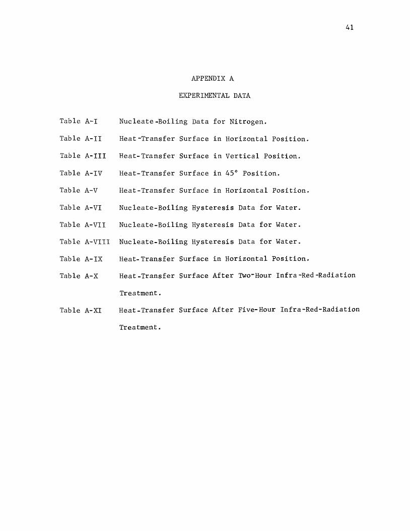
Table A-I
Table A-II
Table A-III
Table A-IV
Table A-V
Table A-VI
Table A-VII
Table A-VIII
Table A-IX
Table A-X
Table A-XI
APPENDIX A
EXPERIMENTAL DATA
Nucleate-Boiling Data for Nitrogen.
Heat-Transfer Surface in Horizontal Position.
Heat- Transfer Surface in Vertical Position.
Heat-Transfer Surface in 45° Position.
Heat-Transfer Surface in Horizontal Position.
Nucleate-Boiling Hysteresis Data for Water.
Nucleate-Boiling Hysteresis Data for Water.
Nucleate-Boiling Hysteresis Data for Water.
Heat-Transfer Surface in Horizontal Position.
41
Heat-Transfer Surface After Two-Hour Infra-Red-Radiation
Treatment.
Heat-Transfer Surface After Five-Hour Infra-Red-Radiation
Treatment.
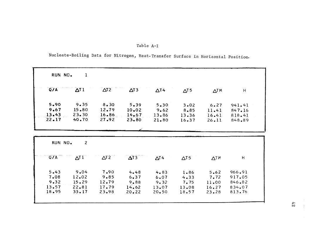
Table A-I
Nucleate-Boiling Data for Nitrogen, Heat-Transfer Surface in Horizontal Position.
RUN NO. 1
Q/A 6T1 6T2 6T3 6T4 6T5 6™ H
5.90 9.35 a. 30 5.39 5.30 3.02 6.27 941.41 9.67 15 .so 12.79 10.02 9.62 8.85 11.41 84 7.16
13.43 23.30 16.~6 l"~'~.Q 1 .. ._,,...._.. . 13.86 13.36 16.41 818.41 22.17 40.70 27.92 23.80 21.80 16.37 26.11 848.89
L
RUN NO. 2
Q/A ·-- 6rr·· 6T2 L\T3 6T4 6T5 6TM H
5.43 9.04 7.90 4.48 4.83 1.86 5.62 966.91 7.08 12.02 9.85 6.37 6.07 4.33 7.72 917.05 9.32 15.29 12.79 9.88 9. 32 7.75 11.00 846.82
..
13.57 22.81 17.79 14.62 13.07 13.08 16.27 834.07 18.95 33.17 23.98 20~t22 20.50 18.57 23.28 813. 76
~ N

Table A-I (Continued)
RUN NO. 3
cilA. ~T1 6T2 613" ~T4 ~T5 ~™ H
5.19 10.52 10.29 5.68 6.12 3.83 7.28 713.46 6.47 13.20 10.49 7.66 8.14 6.34 9.16 706.12 8.03 16.78 14.79 .9. 77 10.35 9.78 12.29 65 3. 32
11.14 22.55 15.77 12.82 15.13 14.58 16.17 6 88.98 14.42 30 .so 21.38 18.64 19.74 19.74 22.06 654.06 17.83 38.63 26.62 23.06 24.93 24.80 2 7.60 645.86 20.55 46.16 31.01 27.30 30.45 28.91 32.76 627.36

44
Table A-II
Nucleate-Boiling Data for Water,
Heat-Transfer Surface in Horizontal Position.
RUN NO. 4
Q/A 6T1 6T2 6T3 6TM H
.65 4.60 2. 50 3.33 3.4 7 187.70 1.95 11.10 5.60 9.07 8.59 22 7. 90 3.91 18.40 8.40 15.66 14.15 2 76.64 6.26 26.60 10.60 23.66 20.28 308.81 8.61 36.40 14.20 33.33 2 7. 97 307.90 9.91 37.40 12.60 36.66 28.88 343.38
11. 15 41.60 13.00 41.00 31.86 350.18 12.39 45.40 13.80 45.33 34.84 355.85 13.70 49.10 15. 33 48.00 3 7.4 7 365.6 7
RUN NO. 5
Q/A 6T1 6T2 6T3 6™ H
1. 17 9.20 4. 60 7.33 7.04 166.77 2.61 16.40 6.20 13.33 11.97 217.95 4.89 25.20 9.00 20.80 1~~33 266.96 7.30 34.20 10 .so 28.33 24.44 299.01 8.54 38.00 11.50 33.33 2 7.61 309.62 9.85 40.66 12.20 36.33 29.73 331.44
11.09 45.40 12.66 40.66 32.90 337.13 12.39 49.10 13.00 46.00 36.03 344.09
13.70 52.80 13.50 49.66 3 ~-!65 354.54
45
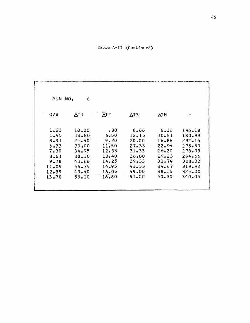
Table A-II (Continued)
RUN NO. 6
Q/A ~T1 ~T2 6T3 6™ H
1.23 10.00 • 30 8.66 6.32 196.18 1.95 . 13.80 6.50 12.15 10.81 180.99 3.91 21.40 9.20 20.00 16.86 2 32 .14 6.33 30 .oo 11.50 27.33 22.94 2 75.89 7.30 34.95 12.33 31.33 26.20 2 78.93 8.61 38.30 13.40 36.00 29.23 294.66 9.78 41.66 14.25 39.33 31.74 308.33
11.09 45.75 14.95 43.33 34.67 319.92 12.39 49.40 16.05 49.00 38.15 325.00 13.70 53.10 16'.ao 5l~OO 4(f.30 340.05
46
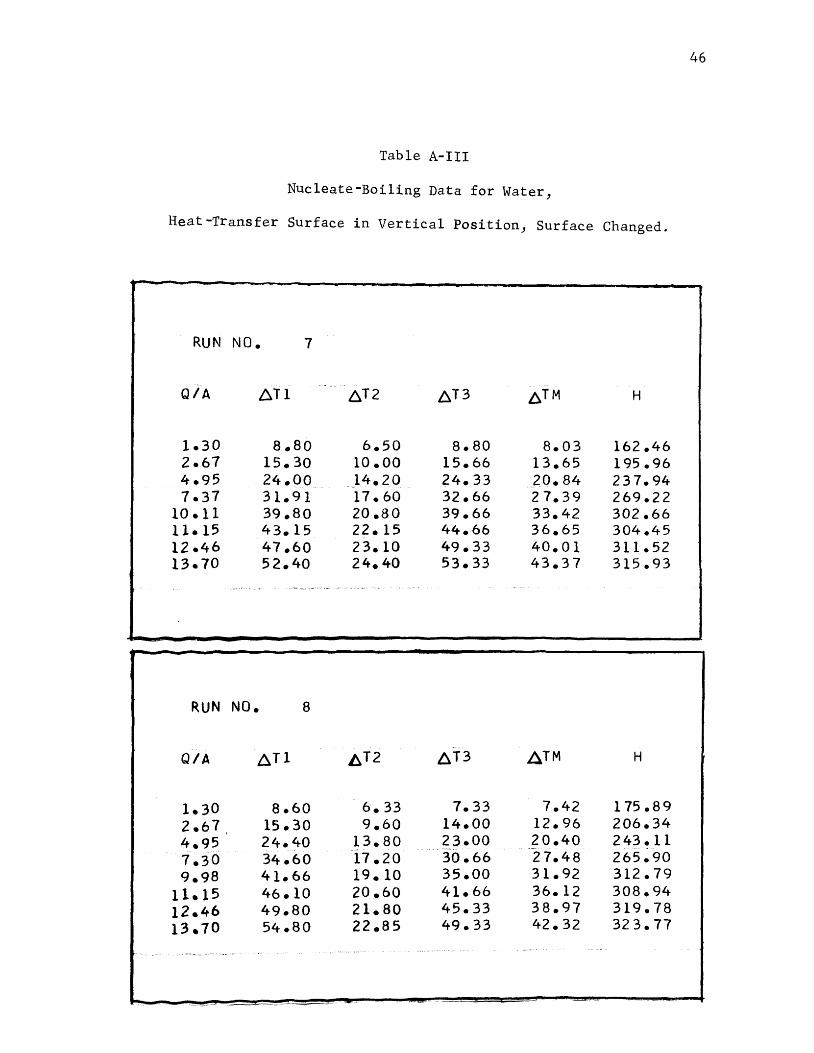
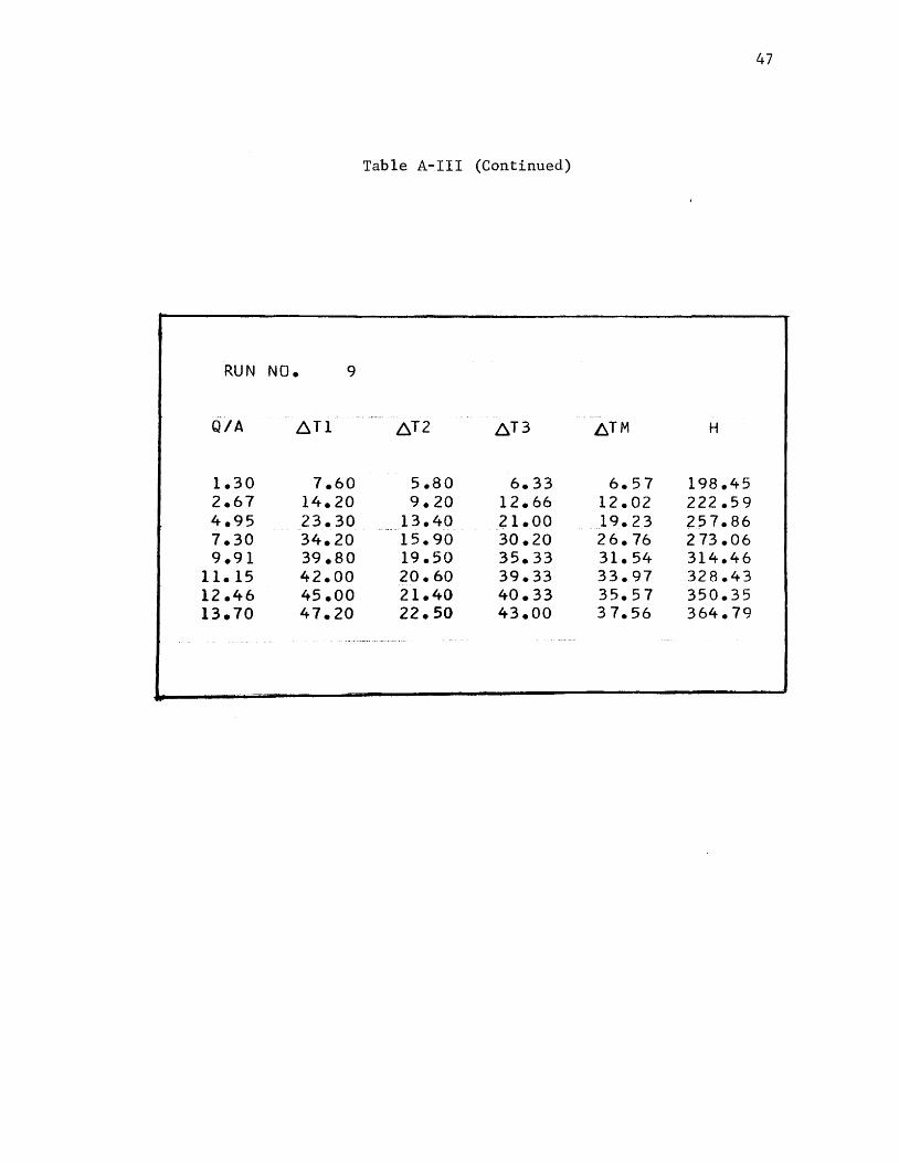
Table A-III
Nucleate-Boiling Data for Water,
Heat-Transfer Surface in Vertical Position, Surface Changed.
RUN NO. 7
Q/A ~T1 6T2 ~T3 6™ H
1.30 a.ao 6.50 a.ao 8.03 162.46 2.67 15.30 10 .oo 15.66 13.65 195.96 4.95 24.00 14.20 24.33 20.84 237.94 7.37 31.91 17.60 32.66 2 7. 39 269.22
10 ell 39.80 20.80 39.66 33.42 302.66 llal5 43.15 22.15 44.66 36.65 304.45 12.46 47.60 23.10 49.33 40.01 311.52 13.70 52.40 24.40 53.33 43.37 315.93
RUN NO. 8
Q/A AT1 ~T2 AT3 A™ H
1.30 8.60 6.33 7.33 7.42 175.89 2.67, 15.30 9.60 14.00 12.96 206.34 4.95 24.40 13.80 23.00 20.40 243.11 7.30 34.60 17.20 30.66 27.48 265.90 9.98 41.66 19. 10 35.00 31.92 312.79
11.15 46.10 20.60 41.66 36.12 308.94 12.46 49.80 21.80 45.33 38.97 319.78 13.70 54.80 22.85 49.33 42.32 32 3. 77
47
Table A-III (Continued)
RUN NO. 9
Q/A ~T1 ~T2 ~T3 ~TM H
1.30 7.60 5.80 6.33 6.57 198.45 2.67 14.20 9.20 12.66 12.02 222.59 4.95 23.30 ,13.40 _2.1.00 19.23 257.86 7.30 34.20 15.90 30.20 26.76 2 73.06 9.91 39.80 19.50 35.33 31.54 314.46
11. 15 42.00 20.60 39.33 33.97 328.43 12.46 45.00 21.40 40.33 35.57 350.35 13.70 47.20 22.50 43.00 3 7.56 364.79

Table A-IV
Nucleate-Boiling Data for Water,
Heat-Transfer Surface in 45° Position.
RUN NO. 10
Q/A ~Tl 8T2
1.30 6.90 5.8o 2.61 11.50 9.90 5.02 17.60 14.20 7.30 22.70 16.80 9.91 27.00 19.50
11.15 28.91 20.80 12.46 31.20 23. 10 13.70 33.40 24.60
RUN NO. 11
1.10 2.61 4.63
.. 7:"24·--· 9.78
11.09 12.39 13.57
Jl.T2
7.90 4.60 15 .eo 8. 40 17.60 12.60 2 3 ~ ffo --- -···--r6· ~ ~ro·»·-··- · 28.50 20.40 30.40 22.15 34.90 28.10 37.50 30.80
.D.T3 ~TM
7.33 6.67 13.33 11.5 7 21.33 17.71 28.66 22.72 36.33 2 7. 61 39.33 29.68 43.00 32.43 46.33 34.77
-~t3 ~TM
5.33 5.94 12.00 12.06 19.33 16.51 "2'"5--~ 33 -----·--~--2·i·--~·97
33.00 27.30 37.00 29.85 39.00 34.00 43.33 37.21
H
195 .48 22 5.48 2 83. 73 321.69 359.26 375.98 384.30 394.06
H
186.66 216.32 280.63 329.60 358.56 3 71.65 364.6 7 364.78
48

49
Table A-IV (Continued)
RUN NO. 12
0.7A 6T1 - ------- LST 2 ~T3 6TM H
1.10 6.70 5.00 6.66 6.12 181.27 2.67 11.50 10.15 14.66 12.10 221.06 4.95 19.10 14.55 23.66 19.10 259.62 1.37 27.45
- -17.40 .. 32.33 --·-25. 72 286.63 9.91 32.60 19.10 39.66 30.45 325.71
11.09 35.10 23.60 45.66 34.78 318.91 12.39 37.90 28.10 49.00 38.33 323.45 13.83 39.00 29.60 51.33 39.97 346.06
50
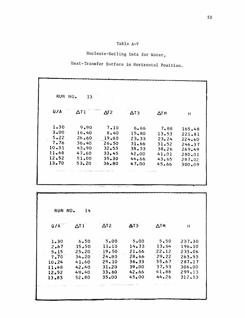
Table A-V
Nucleate-Boiling Data for Water,
Heat-Transfer Surface in Horizontal Position.
RUN NO. 13
Q/A 6T1 ..
··~-~····-
6T2 6T3 6TM H
1.30 9.90 7.10 6.66 7.88 165.48 3.00 16.40 a. 40 15.80 13.53 221.81 5.22 26.60 19 .so 23.33 23.24 224.60 7.76 36.40 26.50 31.66 31.52 246.37
10.31 43.90 32.55 38.33 38.26 269.49 11.48 47.60 33.45 42.00 41.01 280.01 12.52 51.00 35.30 44.66 43.65 287.02 13.70 53.20 36.80 47.00 45.66 300.09
RUN NO. 14
Q/A ~T1 ~T2 &T3 6TM H
1.30 6.50 5.00 5.00 5.50 237.30 2.67 15 .so 11.10 14.33 13.64 196.10 5.15 25.20 19.50 21.66 22.12 2 33.06 7~1b 34.20 '24.80 28.66 .. 29.22 263.53
10.24 41.60 29. 10 36.33 35.67 287.17 11.48 42.40 31.20 39.00 37.53 306.00 12.52 49.40 33.60 42.66 41.88 2 99. 13 13.83 52.80 35.00 45.00 44.26 312.53
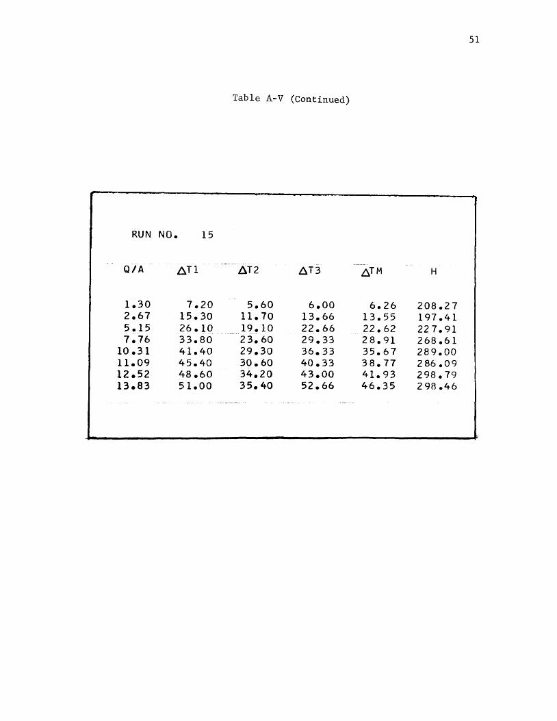
51
Table A-V (Continued)
RUN NO. 15
Q/A ~T1 L\T2 ,!\T3 6™ H
1.30 7.20 5.60 6.00 6.26 208.27 2.67 15.30 11.70 13.66 13.55 197.41 5.15 26.10 19.10 22.66 22.62 22 7. 91 7.76 33.80 23.60 29.33 28.91 268.61
10.31 41.40 29.30 36.33 35.67 289.00 11.09 45.40 30.60 40.33 38.77 286.09 12.52 48.60 34.20 43.00 41.93 298.79 13.83 51.00 35.40 52.66 46.35 2 98.46
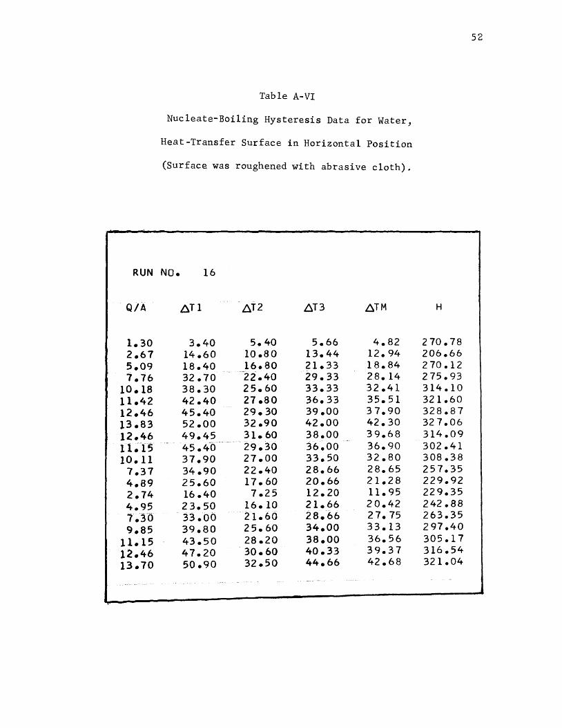
Table A-VI
Nucleate-Boiling Hysteresis Data for Water,
Heat-Transfer Surface in Horizontal Position
(Surface was roughened with abrasive cloth).
RUN NO. 16
Q/A 6Tl 6T2 ~T3 ~TM
1.30 3.40 5. 40 5.66 4.82 2.67 14.60 10.80 13.44 12.94 5.09 18.40 16.80 21.33 18.84 7.76 32.70 -22.40 29.33 28.14
10.18 38.30 25.60 33.33 32.41 11.42 42.40 21 .ao 36.33 35.51 12.46 45.40 29.30 39.00 3 7.90 }3.83 52.00 32.90 42.00 42.30 12.46 49.45 31.60 38.00 39.68
--
11~15 -- 45 .4·a··--· 29.30 36.00 36.90
10.11 37.90 27.00 33.50 32.80 7.37 34.90 22.40 28.66 28.65 4.89 25.60 17.60 20.66 21.28 2.74 16.40 7.25 12.20 11.95 4.95 23.50 16. 10 21.66 20.42 l.~ro 33.bb 21.60 28.66 27.75 9.85 39.80 25.60 34.00 33.13
11.15 43.50 28.20 38.00 36.56
12.46 47.20 30.60 40.33 39.3 7
13.70 50.90 32.50 44.66 42.68
. '
52
H
2 70.78 206.66 2 70.12 2 75.93 314.10 321.60 328.87 32 7.06 314.09 302.41 308.38 257.35 229.92 229.35 242.88 263.35 2 97.40 305.17 316.54 321.04
53
Table VI (Continued)
RUN NO. 17
. - ~ ..... ~ . . ,_, - ·~ ·-
Q/A 6T1 6T2 6T3 6TM H
1.23 7.40 5.40 5.33 6.04 205.16 2.67 15.10 11.30 11.66 12.68 210.89 5.09 23.10 16 .so 19.00 19.63 259.25 7.56 31.20 21.60 24.66 25.82 2 93.18 9.98 38.30 26.70 30.60 31.86 313.32
11.22 42.80 28.90 33.33 35.01 320.60 12.46 46.80 31.40 36.66 38.28 32 5. 55 13.70 50.90 34.20 39.66 41.58 329.53 12.46 47.60 31.20 36.66 38.48 32 3. 86 '1.i.i5 44.60 26.60 34.00 35.06 318.22
9.85 40.60 28.66 32. 19 33.81 291.39 7.17 32.50 21.80 26.90 2 7.06 2 65.21 4.63 25.15 16.10 20.33 20.52 225.72 2.61 15.30 10.70 13.00 13.00 200.79 1.23 a.oo 5.40 7.00 6.80 182.33
. ·-· ~ •··
- -
RUN NO. 18
Q/A ~T1 6T2 ~T3 ~TM H
1.23 4.60 3.90 1. 33 3. 27 378.40 2.61 11.90 8.00 7.33 9.07 287.58 4.89 19 .so 13.20 14.00 15.66 312.40 7.30 28.90 18.30 21.50 22.90 319.16 9.91 37.90 23.30 26.33 29.17 339.97
11.15 41.30 26.00 28.33 31.87 350.07 12.39 44.60 28.60 30.66 34.62 358.14 13.63 47.40 30.40 33.33 3 7.04 368.18 12.39 45.40 29.30 31.66 35.45 349.72 11.09 42.80 28.20 30~00 33.66 329.52 9.85 39.00 26.30 27.66 30.98 318.00 7.24 30.80 20.80 23.00 24.86 2 91.2 9 4.56 23.90 16.10 17.33 19.11 239.04 2.61 15.30 10.00 12.00 12.43 209.94 1.30 11.10 5.60 6.33 7.67 170.01
~--'" ~- ..... ... .. . . -··-~ ·- ...... ~- ~ ·-··· ..... ___ -
.C
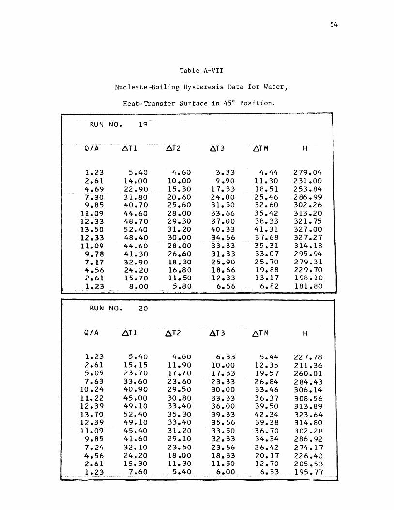
54
Table A-VII
Nucleate-Boiling Hysteresis Data for Water,
Heat-Transfer Surface in 45° Position.
RUN NO. 19
·----
Q/A- 6T1 6T2 6T3 6TM H
1.23 5.40 4.60 3.33 4.44 279.04 2.61 14.00 10.00 9.90 11.30 231.00 4.69 22.90 15.30 17.33 18.51 253.84 7.30 31.80 20.60 24.00 25.46 2 86.99 9.85 40.70 25.60 31.50 32.60 302.26
11.09 44.60 28.00 33.66 35.42 313.20 12.33 48.70 29.30 37.00 38.33 321.75 13.50 52.40 31.20 40.33 41.31 327.00 12.33 48.40 30.00 34.66 37.68 32 7.2 7 11.09 44.60 28.00 33.33 35.31 314.18 9.78 41.30 26.60 31.33 33.07 295.94 7.17 32.90 18.30 25.90 25.70 2 79.31 4.56 24.20 16.80 18.66 19.88 22 9. 70 2.61 15.70 11.50 12.33 13.17 198.10 1.23 a.oo 5.80
"' .. 6~.6~ 6.82 181.80 -· - -
RUN NO. 20
Q/A 6T1 ~T2 6T3 ~TM H
1.23 5.40 4.60 6.33 5.44 22 7. 78 2.61 15.15 11.90 10.00 12.35 211.36 5.09 23.70 17.70 17.33 19.57 260.01 7.63 33.60 23.60 23.33 26.84 284.43
10.24 40.90 29.50 30.00 33.46 306.14 11.22 45.00 30.80 33.33 36.37 308.56 12.39 49.10 33.40 36.00 39.50 313.89 13.70 52.40 35.30 39.33 42.34 323.64 12.39 49.10 33.40 35.66 39.38 314.80 11.09 45.40 31.20 33.50 36.70 302.2 8 9.85 41.60 29.10 32.33 34.34 286.92 7.24 32.10 23.50 23.66 26.42 2 74.17 4.56 24.20 18 .oo 18.33 20.17 226.40 2.61 15.30 11.30 11.50 12.70 205.53 1.23 7.60 5.40 6.00 6.33 195.77
-·· -·· -· ~-· ... ·- ~
55
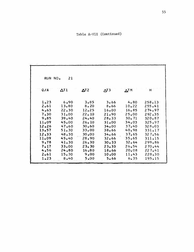
Table A-VII (Continued)
RUN NO. 21
Q/A 6T1 /j.T2 6T3 A™ H
1.23 6.90 3.85 3.66 4.80 258.13 2.61 13.80 a. 20 8.66 10.22 255.41 4.63 22.30 12.25 16.00 16.85 274.97 7.30 31.00 22. 10 21.90 25.00 292.35 9.85 39.40 24.40 28.33 30.71 32 0. 8 7
11.09 45.00 26.10 31.00 34.03 325.97 12.26 47.60 30.60 34.00 37.40 328.03 13.57 51.30 33.00 38.66 40.98 331.17 12.33 48.30 30.00 34.66 37.65 32 7. 56
·-
11.09 45.40 28.90 32.66 35.65 311.15 9.78 41.30 26.30 30.33 32.64 299.86 7.17 33.00 23.30 23.33 26.54 2 70.44 4.56 24.80 16.80 18.66 20.08 22 7. 41 2.61 15.30 9.00 10.00 11.43 228.30 1.23 8.40 s.oo 5.66 6.35 195.15

56
Table A-VIII
Nucleate-Boiling Hysteresis Data for Water,
Heat-Transfer Surface in Vertical Position
RUN NO. 22
Q/A 6T1 6T2 6T3 6TM H
1.30 8.oo 7.40 6.16 7.18 181.60 2.67 17.00 15.70 12.66 15.12 176.95 5.22 28.40 25.40 20~ 50 24.76 210.79 -;. 76 37.90 31.90 27.33 32.37 239.85
10.31 45.75 36.80 33.33 38.62 266.93 11.48 50.20 38.70 36.66 41.85 2 74.42 12.59 55.40 41.70 39.33 45.4 7 276.95 13.83 58.40 44.60 41.33 48.11 287.56 12.52 53.90 40.60 39.66 44.72 280.17 11.22 49.40 37.90 3 7. 33 41.54 2 70. 18 9.98 45.40 34.90 35.00 38.43 259.78 7.30 37.60 31.20 2 7.33 32.04 228.09 4.69 27.80 24.20 20.66 24.22 193.99 2.61 17.60 15.30 12.50 15.13 172 .48 1.30 9.20 7.&0 6.66 7.82 166.90
~
RUN NO. 23
Q/A 6T1 8T2 6T3 ~TM H
2.61 14.90 13.80 a. so 12.40 210.51 4.95 23.50 22.90 16.66 21.02 235.94 7.24 3? .10 30.60 26.00 29.56 244.99 9.91 39.40 34.40 31.33 35.04 2 83 .os
11.15 43.10 36.40 33.00 37.50 297.5 7 12.52 49.10 37.90 35.66 40.88 306.44 13.70 52.80 39.40 39.33 43.84 312.57 12.46 49.40 37.40 36.33 41.04 303.68 11.15 45.80 34.90 34.00 38.23 291.86 ··9. 78 41.70 32.30 33.33 35.77 2 73.60 7.17 30.40 28.85 26.00 28.41 252.61 4.69 23.30 21.60 18.00 20.96 224.09 2.61 14.00 13.05 11.33 12.79 204.03
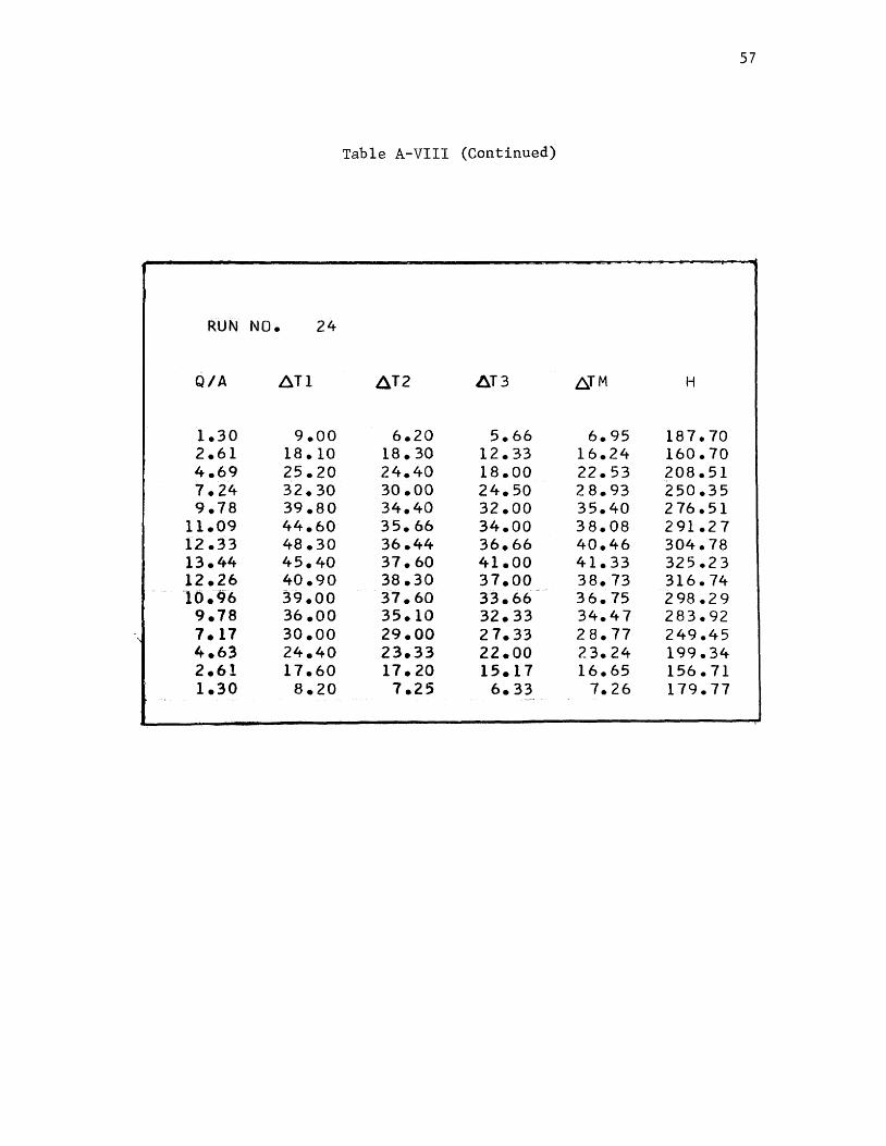
57
Table A-VIII (Continued)
RUN NO. 24
Q/A 6T1 ~T2 ~T3 ~TM H
1.30 9.00 6.20 5.66 6.95 187.70 2.61 18.10 18.30 12.33 16.24 160.70 4.69 25.20 24.40 18.00 22.53 208.51 7.24 32.30 30.00 24.50 2 8. 93 250.35 9.78 39.80 34.40 32.00 35.40 2 76.51
11.09 44.60 35.66 34.00 38.08 291.27 12.33 48.30 36.44 36.66 40.46 304.78 13.44 45.40 37.60 41.00 41.33 32 5. 2 3 12.26 40.90 38.30 37.00 38.73 316. 74 10.96 ~9.00 37.60 33.66
-36.75 2 98.2 9
9.78 36 .oo 35.10 32.33 34.47 283.92 \ 7.17 30.00 29.00 2 7.33 28.77 249.45
4.63 24.40 23.33 22.00 23.24 199.34 2.61 17.60 17.20 15.17 16.65 156.71 1.30 8.20 7.25 6.33 7.26 179.77

58
Table A-IX
Nucleate-Boiling Data for Water,
Heat-Transfer Surface in Horizontal Position, Clean Surface.
RUN NO. 25
Q/A 6T1 6T2 AT3 ~TM H
1.30 5.80 5.60 2.33 4.57 285.17 3.13 13.20 13.00 8.oo 11.40 2 74.77 5.22 20.60 20.60 14.00 18.40 283.73 7.83 28.60 28.60 20.00 2 5. 73 304.31
10.44 35.60 36.00 25.90 32.50 321.2 7 11.74 38.30 37.90 28.00 34.73 338.18 12.98 41.33 41.33 30.00 37.55 345.81 14.09 44.60 44.60 33.00 40.73 346.04
RUN NO. 26
Q/A 6Tl ~T2 6T3 6TM H
1.17 4.80 3. 60 1.66 3.35 350.29 2.61 11.50 11.50 4.66 9.22 283.11 4.69 19.10 18.90 11.66 16.55 2 83.84 7.30 27.40 28.20 15.33 23.64 309.13 9.98 34.60 35.50 22.33 30.81 324.06
11.15 37.20 37.90 24.66 33.25 335.57 12.46 40.70 40.90 26.66 36.08 345.39 13.63 43.90 44.60 29.66 39.38 346.28
59
Table A-X
Nucleate-Boiling Data for Water,
Heat-Transfer Surface in Horizontal Position,
Two-Hour Infra-Red-Radiation Treatment.
RUN NO. 27
-·oii t:.t 1 ~T2 ~T3 ~TM H
1.30 7.85 8.oo 7.33 7. 72 168.91 3.06 15.10 15.30 13.66 14.68 208.83 5.22 22.90 22.90 20.50 22.10 236.22 7.83 30.60 31.00 28.50 30.03 260.74
10.37 37.85 38.30 35.33 3 7. 16 279.22 11.61 41.30 41.30 38.00 40.20 2 88.95 12.85 43.50 43.50 40.33 42.44 302.89 13.96 46.10 46.10 43.66 45.28 308.3 7
RUN NO. 28
Q/A ~T1 ~T2 6T3 ~™ H
1.23 6.15 6.15 3.33 5.21 237.98 2.61 12.85 12.40 8.00 11.08 235.51 4.95 20.80 21.00 14.23 18.67 265.55 7.56 28.60 28.90 ii~oo 26.16 289.29
10.24 36.00 36.20 27.33 33.17 308.81 11.28 38.66 38.66 29.66 35.66 316.59 12.52 41.66 41.30 32.00 38.32 326.97 13.70 44.25 44.60 33.66 40.83 335.58
60
Table A-XI
Nucleate-Boiling Data for Water,
Heat-Transfer Surface in Horizontal Position,
Five-Hour Infra-Red-Radiation Treatment.
RUN NO. 29
Q/A ~Tf · 6t2 6T3 ~TM H
1.30 9.80 8.40 6.33 8.17 159.62 3.19 16.40 15.50 11.66 14.52 220.22 5.22 24.60 23.60 18.50 22.23 234.81 7.83 32.50 31.60 28.33 30.81 2 54.16
10 .so 38.30 37.60 33.50 36.46 288.11 11.74 41.60 40.60 39.33 40.51 289.96 13.05 45.00 43.10 40.66 42.92 304.09 14.09 48.00 46.10 44.33 46.14 305 .4 7
RUN NO. 30
Q/A ~T1 6T2 6T3 bTM H
1.04 6.50 5.80 3.50 5.26 198.25 2.61 14.00 13.00 8.33 11.77 221.65 4.69 22.33 21.44 15.33 19.70 238.50 7.24 30.60 29.70 21.33 2 7. 21 266.21 9.85 37.40 36.40 29.33 34.37 2 86.64
11.22 39.80 38.30 31.00 36.36 308.64 12.46 42.80 41.70 32.00 38.83 320.96 13.70 46.10 45.40 33.55 41.68 32 8. 76
61
APPENDIX B
SAMPLE CALCULATIONS

Sample Calculation for the First Data Point of Run 4:
Similarly,
2l0°F corresponds to 4.225 mV
First Thermocouple Reading = 0.12 mV
4.425 + 0.12 = 4.345 mV
4.345 mV corresponds to 214.6°F
T2 =
T3 =
i.e.
2.5°F
3.33°F
T = m 3.48°F
w = 10 Watts
A= 0.0523 Ft~
Q/A = (3.413 W)/A
= (3.413 X 10)/0.0523
= 653 Btu/Hr. Ft?
62
APPENDIX C
COMPUTER PROGRAM FOR CALCULATIONS
OF
HEAT FLUX
AND
HEAT-TRANSFER COEFFICIENTS
63

Read area and Read energy
total number input for one
of runs run
Sum temperature Read temperature
differences differences
Calculate mean temperature differences, heat flux and heat transfer coefficients
Test for
number
of runs
Figure 12. Flow Sheet for the Computer Program
64

:::~LIST PRINTER *ALL STATEMENT MAP c -c-~,-~(-~'-64-o "1~6c··N)<"O 2 3·-·----t-HE v Al~-r---H·· -o---c BOILING HEAT TRANSFER
DIMENSION OT ( 3) --· READ 66·;-A·----------------·------------
READ 40,L DO 30 JS=1,L
·--ffEirtY 40, R-; M, N P=M PRINT 80
65
07/06/66 FORTRAI\J t
--- --------------pf{Ti\Tr-1 o o"~-N-· ----··-·-- -----. --- ·--- -- --·-- -- ·--------------------------PRINT 110 PRINT 90 PRINt ··120 DO 20 1=1,K READ 50,W,CDT(J),J=1,M) -·-------- S=O ;o ___________ - -- ---------· ---------- --------- ---------------·· DO 10 J=l,M S=S+DT(J)
1 o t tif\r·rr NTJ E DTM=S/P QA=3.413~:WJA
. ---·- -------f.f=Q A /-DTM- -- ----------------------------------QB=QA/1000. PRINT 70,QB 9 (0T(J),J=1 9 M),OTM,H
20 CONTINUE ------30 CONTINUE
CALL EXIT .... -··· ........ --- ·-----·-···---- -------------------------------- ----- ------------------------------
40 FORMAT(315) 50 FORMAT(4Fl0.2) 60 FORMAT(El8.8) 70 FORMAT(6F9.2) 80 FORMAT(lH1) 90 FORMATC5X,46HQ/A Tl T2
--1 bo --··r:'fJRMAT·n;-x 7 HR u N -f\Hr;-, -.-1 -;::-5.-) ------110 FORMAT(/) 120 FORMAT(/)
END
T3
66
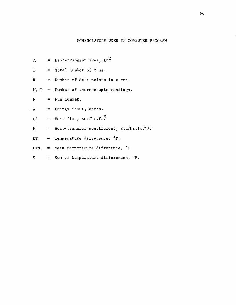
NOMENCLATURE USED IN COMPUTER PROGRAM
A = Heat-transfer area, ft?
L = Total number of runs.
K = Number of data points in a run.
M, p = Number of thermocouple readings.
N = Run number.
w = Energy input, watts.
QA = Heat flux, But/hr.ft~
H = Heat-transfer coefficient, Btu/hr.ft?°F.
DT = Temperature difference, °F.
nrn = Mean temperature difference, °F.
s = Sum of temperature differences, °F.

67
VITA
The author of this thesis was born on April 7, 1940 in Surat,
India. He received his primary and secondary education in Surat, India.
He studied basic science at M. T. B. College, Surat, India. He joined
the Indian Institute of Technology, Bombay, India in July, 1959, and
received a degree of Bachelor of Technology in Chemical Engineering in
December, 1963.
In the spring of 1965, he enrolled as a candidate for the degree
of Master of Science in Chemical Engineering at the University of
Missouri at Rolla.