Embed Size (px)
Citation preview
1 % - I d
_ - c
- . r' h .
Teehnieul Report No. 32-125
Experimenfol lnuestigution of fhe Forced-Conuection and Nucleate-Boiling
Heat-Transfer Characteristics of liquid Ammonia
JET P R O P U L S I O N L A B O R A T O R Y C A L I F O R N I A lNSTITUTE O F TECHNOLOGY
P A S A D E N A , CALI F O R N I A
July 19, 1961
GPO PRICE $
CFSTl PRICE(S) $
Hard copy (HC) 1.6a Microfiche (MF)
ff 653 July 85
https://ntrs.nasa.gov/search.jsp?R=19660030661 2018-07-09T08:51:52+00:00Z
NATIONAL AERONAUTICS AND SPACE ADMINISTRATION
CONTRACT NO. N A S W - 6
Technical Report No. 32-125
Experimental Inuestigation of the Forced-Conuection and Nucleate-Boiling
Heat -Trans fer Characteristics of Liquid Ammonia
M. B. Noel
4 D. R. Bartz, Chief Propulsion Research
J E T P R O P U L S I O N L A B O R A T O R Y
PASADENA, CALIFORNIA
C A L I F O R N I A INSTITUTE O F TECHNOLOGY
July 19, 1961
. .
J P L TECHNICAL REPORT NO. 32-125
Copyright 01 961 Jet Propulsion laboratory
California Institute of Technology
J P L TECHNICAL REPORT NO . 32-125
CONTENTS
II . Forced-Convection Nucleate-Boiling Test Apparatus . . . . . 2
111 . lnshumentation . . . . . . . . . . . . . . . . . . . 3
IV . Pool-Boiling Apparatus . . . . . . . . . . . . . . . . 4
V . Data Computation . . . . . . . . . . . . . . . . . . 5 A . HeatFlux . . . . . . . . . . . . . . . . . . . . . 5 B . Heat Flux at the Upper Limit of Nucleate Boiling 5 C . Liquid-Side Wall Temperature . . . . . . . . . . . . . 6
. . . . . . .
VI.Resulb . . . . . . . . . . . . . . . . . . . . . . . 6
A . General . . . . . . . . . . . . . . . . . . . . . . 6 B . Nonboiling Region . . . . . . . . . . . . . . . . . . 6 C . Nucleate-Boiling Region . . . . . . . . . . . . . . . . 7 D . Upper Limit of Nucleate Boiling . . . . . . . . . . . . . 9 E . Total Heat Load . . . . . . . . . . . . . . . . . . . 9
VI1 . Conclusions . . . . . . . . . . . . . . . . . . . . . 13
Nomenclature . . . . . . . . . . . . . . . . . . . . . . 13
References . . . . . . . . . . . . . . . . . . . . . . . 14
TABLES
1 . Values of quz . . . . . . . . . . . . . . . . . . . . . . 11

J P L TECHNICAL REPORT NO . 32-125
1 . Flow circuit . . . . . . . . . . . . . . . . . . . . . . 2 2 . Test-section and wall-thermocouple installation . . . . . . . . . 3 3 . Bulk-temperature thermocouple . . . . . . . . . . . . . . . 4 4 . Pool-boiling apparatus . . . . . . . . . . . . . . . . . . 5 5 . Heat flux as a function of temperature difference for various
pressures with constantvelocity and bulk temperature . . . . . . . 7 6 . Correlation of nonboiling forced-convection data
with the Sieder-Tote equation . . . . . . . . . . . . . . . 7 7 . Heat flux as a function of wall temperature for a velocity of
30 ft/sec and an inlet liquid bulk temperature of 5O0F . . . . . . . 7 8 . Heat flux as a function of wall temperature for a pressure of
500 psia and a bulk temperature of 55OF*5 . . . . . . . . . . 8 9 . Heat flux at the upper limit of nucleate boiling
as a function of pressure . . . . . . . . . . . . . . . . . 8 10 . Heat flux at the upper limit of nucleate boiling as a function of
velocity for various liquid bulk temperatures at a pressure of 500 psia . 8 11 . Heat flux at the upper limit of nucleate boiling as a function of
liquid bulk temperature for various velocities at a pressure of 500 psia . 9 12 . Viscosity of ammonia as a function of temperature and pressure . . . 10 13 . Specific gravity of ammonia as a function of temperature . . . . . . 10 14 . Specific heat of ammonia as a function of temperature . . . . . . . 10 15 . Thermal conductivity of ammonia as a function of temperature . . . . 11 16. Vapor pressure of ammonia as a function of temperature . . . . . . 11 17 . Comparison of experimental values of q?. with E q . (81 . . . . . . . 12

f JPL TECHNICAL REPORT NO. 32-125
ABSTRACT 3496' To achieve a safe and effective design for liquid-propellant rocket
engines that are to be regeneratively cooled, knowledge of the heat- transfer characteristics of the propellant that is to be used as the coolant is essential. For many propellants, such as ammonia, the upper limit of nucleate boiling must be considered as the practical limit of the cooling capability of a propellant for rocket-engine application. At higher heat fluxes lies the film-boiling region, which requires excessive surf ace temperatures to accommodate the characteristically low heat- transfer coefficients. The heat-transfer characteristics of commercial- grade anhydrous ammonia have been obtained experimentally by utilizing electrically heated tubes. A total of fifty-five tests were per- formed, including measurements in the forced-convection nonboiling and forced-convection nucleate-boiling regions. The upper limit of nucleate boiling 9ul has been determined for ranges of velocity, pres- sure, and liquid bulk temperature that include velocities between 0 and 156 ft/sec, pressures between 150 and 1820 psia, and liquid bulk tem- peratures between 23 and 158°F. The values of 9ur varied from 2 to 14 Btu/in.* sec, depending upon the particular flow condition. An inter- polation equation is presented that may be used to predict qUl within the ranges of pressure, velocity, and liquid bulk temperature tested.
1. INTRODUCTION
One of the problems facing the liquid-propellant rocket- engine design engineer is the cooling of combustion- chamber and nozzle walls. If conventional nonrefractory metals, such as stainless steel or aluminum, are used for thrust-chamber liners, cooling by radiation to the sur- roundings is inadequate for most engine operating con- ditions. Regenerative cooling, which utilizes one of the
propellants as a coolant prior to injection, is the most feasible means of maintaining wall temperatures SIB- ciently low to retain adequate strength of liner materials. The heat fluxes encountered in rocket engines are gen- erally so high that impractically high c d a n t velocities are required to prevent transition to nucleate boiling (sometimes called local or surface boiling). In the sub-
1
Y JPL TECHNICAL REPORT NO. 32-125
cooled nucleate-boiling region the liquid coolant is below the saturation temperature and the heat flux is so high that bubbles grow and collapse on the heated surface as the fluid flows along the passage. If, for a particular con- dition, the coolant bulk temperature, pressure, and veloc- ity are fixed but the local heat flux is increased, the population density of the bubbles increases. At a suffi- ciently high local heat flux, the bubbles will coalesce to form a vapor film, which induces a high resistance to heat flow through the film thickness; as a result, a large increase in the surface temperature results. This condition is termed film boiling. For many liquid propellants (includ-
ing ammonia), the wall temperature becomes SO high in the film-boiling region that stainless steel melts. Conse- quently, the heat flux at the upper limit of nucleate boil- ing may be considered as the limiting capability of a liquid propellant to cool a local surface area on a rocket- engine component. Therefore, a knowledge of the heat- transfer characteristics at the upper limit of nucleate boiling for the propellant to be used as a regenerative coolant is essential to achieve a safe and effective rocket- engine design (Ref. 1). Experimental measurements have been made to determine these heat-transfer characteristics of commercial anhydrous ammonia.
II. FORCED-CONVECTION NUCLEATE-BOILING TEST APPARATUS
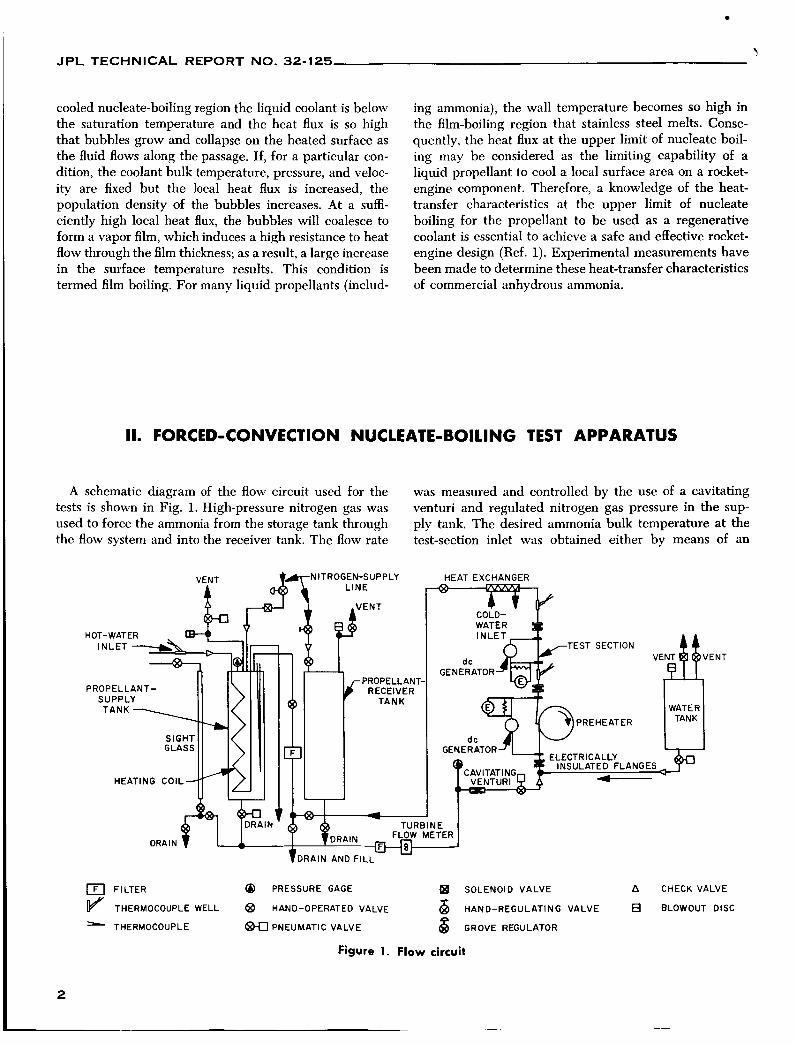
A schematic diagram of the flow circuit used for the tests is shown in Fig. 1. High-pressure nitrogen gas was used to force the ammonia from the storage tank through the flow system and into the receiver tank. The flow rate
was measured and controlled by the use of a cavitating venturi and regulated nitrogen gas pressure in the SUP-
ply tank. The desired ammonia bulk temperature at the test-section inlet was obtained either by means of an
TEST SECTION ENT
PROPELLANT- SUPPLY
PREHEAT ER
HEATING COIL
a FILTER @ PRESSURE GAGE a SOLENOID VALVE A CHECK VALVE
THERMOCOUPLE WELL @ HAND-OPERATED VALVE HAND-REGULATING VALVE BLOWOUT DISC - THERMOCOUPLE PNEUMATIC VALVE 8 GROVE REGULATOR
Figure 1. Flow circuit
2
JPL TECHNICAL REPORT NO. 32-125
electrically heated preheater tube or, when cooling was necessary, by precooling the supply tank containing the ammonia.
Two sizes of Type 347 stainless-steel circular tube test sections were used, having dimensions in inches of 0.25 outside diameter, 0.009 wall thickness, and 3.15 length and 0.188 outside diameter, 0.015 wall thickness, and 3.15 length, respectively. An unheated length of tube approxi-
mately 5.8 in. long preceded the heated portion of the test section. The ammonia flowed through the inside of the vertically mounted tubes, and the heat applied to the test section was generated electrically within the tube walls with power supplied by dc welding generators. A more detailed description of the test apparatus and power supply, including tube-wall thickness and electrical resis- tance measurement techniques, heat losses and accuracies of measurements, is given in Ref. 2.
111. INSTRUMENTATION
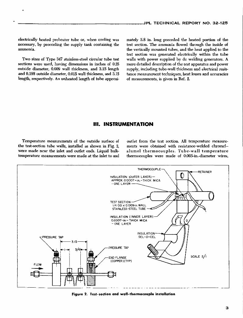
Temperature measurements of the outside surface of the test-section tube walls, installed as shown in Fig. 2, were made near the inlet and outlet ends. Liquid bulk- temperature measurements were made at the inlet to and
outlet from the test section. All temperature measure- ments were obtained with resistance-welded chromel- a lumel thermocouples. Tube-wall t empera ture thermocouples were made of O.OO5-in.-diameter wires,
THERMOCOUPLE
INSULATION (OUTER LAYER)- APPROX. 00007- in . -THICK MICA -ONE LAYER
TEST SECTION 1/4 O D X O O STAINLESS-S
INSULATION ( INNER LAYER) 0.0007-in.- THICK MICA -ONE LAYER
PRESSURE TAP
END FLANGE (COPPER NTYP)
TAINER
TEST SECTION 1/4 OD X 0.0 STAINLESS-S
I SCALE 2/1
Figure 2. Test-section and wall-thermocouple installation
3

J P L TECHNICAL REPORT NO. 32-125
and liquid bulk-temperature thermocouples, which were fused into the end of a glass tube (Fig. 3), were made of 0.010-in.-diameter wires.
Pressures were measured upstream and downstream of the cavitating venturi so that weight flow rates could be
established. A pressure measurement was also made near the outlet of the test section.
Additional information on the details of thermocouple installation and measurement accuracies may be found in Ref. 2.
Figure 3. Buik-temperature thermocouple
IV. POOL-BOILING APPARATUS
The tests at zcro velocity were performed in ;I pool- boiling apparatiis using a T Y ~ W 347 stainlcss-steel strip 0.0043 in. thick, 0.125 in. wide, and 1 in. long, oriented as shown in Fig. 4. The apparatus was essentially a pres- sure vessel, with an oiitside jacket enclosing passsages
which could !)e used for either cooling or heating the internal liquid. Elcctrodes through the cover and into the container supplied power to the test strip. A thermo- couple :llso extended through the cover into the liquid SO t]~;lt liq11id bulk temperature could be measured.
4

I JPL TECHNICAL REPORT NO. 32-125
r
HEATING AND COOLANT FLOW c
I X I / B X 0 . 0 0 4 3
7 in. THICK
VIEW A-A SHOWING GLASS ENCASED CHROMEL-ALUMEL THERMOCOUPLE
ELECTRODES, 430 S.S
U I h
I
Figure 4. Pool-boiling apparatus
V. DATA COMPUTATION
A. Heat Flux A third method used to compute the heat flux consisted of calculating the heat added to the liquid, using the bulk- temperature rise of the liquid aaoss the ta t section and the
The electrical Power supplied to the test Section was used to compute the heat flux from the test section by the equation
weight flow rate.
The estimated precision of the value of q determined from Eq. (1) was 22%. As a check on the electrical meas- urements of the test-section power, the temperature- dependent resistance R was used to calculate the heat flux, using Eq. (2):
Resistance R was evaluated at the average wall tempera- ture of the tube (Ref. 2, Fig. 16). The maximum deviation between the values computed from Eqs. (1) and (2) was 5%.
In general, these results agreed within 5% of those obtained from Eq. (1).
0. Heat Flux at the Upper limit of Nucleate Boiling
Heat flux at the upper limit of nucleate boiling qui was calculated from Eq. (1). The values of the current and voltage used in the equation to establish 9.1 were those measured at the point at which there was a sudden large increase in wall temperature which is characteristic of the transition to film boiling. In nearly all tests, tube failure
5
JPL TECHNICAL REPORT NO. 32-125
occurred simultaneously with this transition. At high bulk temperatures and pressures above lo00 psi there were some tests in which the power could be shut off before tube failure occurred.
C. liquid-Side Wall Temperature
The liquid-side wall temperature was calculated from the measured outside wall temperature and a theoretical temperature difference across the tube wall which was obtained by assuming uniform internal power generation
within the metal wall. The following equation was used for the temperature difference across the tube wall:
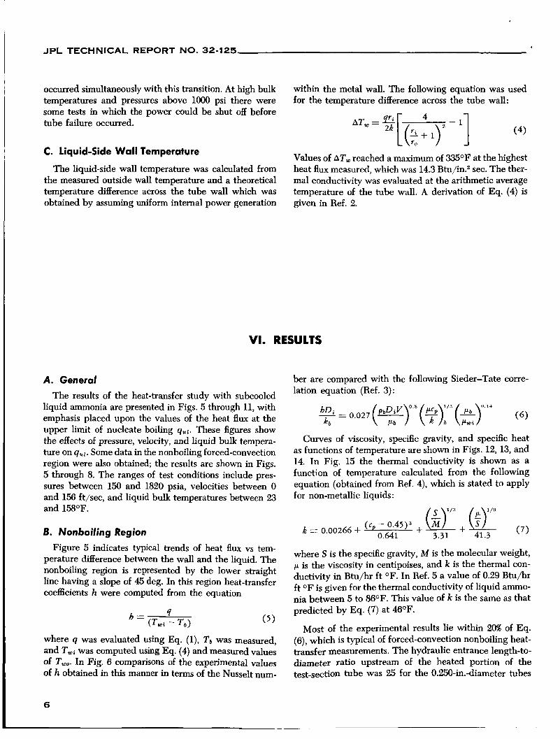
Values of AT, reached a maximum of 3 3 5 O F at the highest heat flux measured, which was 14.3 Btu,h2 sec. The ther- mal conductivity was evaluated at the arithmetic average temperature of the tube wall. A derivation of Eq. (4) is given in Ref. 2.
VI. RESULTS
A. General
The results of the heat-transfer study with subcooled liquid ammonia are presented in Figs. 5 through 11, with emphasis placed upon the values of the heat flux at the upper limit of nucleate boiling quz. These figures show the effects of pressure, velocity, and liquid bulk tempera- ture on qui. Some data in the nonboiling forced-convection region were also obtained; the results are shown in Figs. 5 through 8. The ranges of test conditions include pres- sures between 150 and 1820 psia, velocities between 0 and 156 ft/sec, and liquid bulk temperatures between 23 and 1 5 8 O F .
6. Nonboiling Region
Figure 5 indicates typical trends of heat flux vs tem- perature difference between the wall and the liquid. The nonboiling region is represented by the lower straight line having a slope of 45 deg. In this region heat-transfer coefficients h were computed from the equation
where 9 was evaluated using Eq. (l), Ta was measured, and TWi was computed using Eq. (4) and measured values of Two. In Fig. 6 comparisons of the experimental values of h obtained in this manner in terms of the Nusselt num-
ber are compared with the following Sieder-Tate corre- lation equation (Ref. 3):
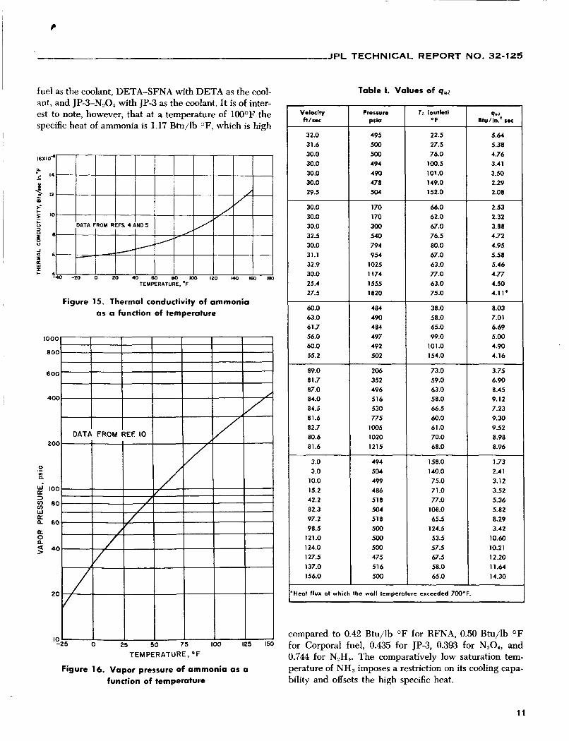
Curves of viscosity, specific gravity, and specific heat as functions of temperature are shown in Figs. 12, 13, and 14. In Fig. 15 the thermal conductivity is shown as a function of temperature calculated from the following equation (obtained from Ref. 4), which is stated to apply for non-metallic liquids:
(;)*':I I (q (7)
(cP - 0.45)3 +
0.641 3.31 41.3 k = 0.00266 + where S is the specific gravity, M is the molecular weight, p is the viscosity in centipoises, and k is the thermal con- ductivity in Btu/hr ft O F . In Ref. 5 a value of 0.29 Btu/hr f t OF is given for the thermal conductivity of liquid ammo- nia between 5 to 86OF. This value of k is the same as that predicted by Eq. (7) at 46OF.
Most of the experimental results lie within 20% of Eq. (e), which is typical of forced-convection nonboiling heat- transfer measurements. The hydraulic entrance length-to- diameter ratio upstream of the heated portion of the test-section tube was 25 for the 0.250-in.-diameter tubes
6

~~ ~~~~ ~
JPL TECHNICAL REPORT NO. 32-125
0. I I O 20 40 60 100 200
Figure 5. Heat flux as a function of temperature difference for various pressures with constant
velocity and bulk temperature
and 37 for the 0.1875in.diameter tubes. These lengths are considered adequate to establish fully developed adia- batic flow conditions. Heated length-todiameter ratios at the outlets of the tubes were 13.6 for the 0.250-in.- diameter tubes and 20.0 for the 0.1875-in.-diameter tubes. Based on the results of Ref. 6, these length-to-diameter ratios are considered adequate to eliminate thermal entrance effects. The wall temperatures and heat-transfer coefficients refer to values near the tube outlets.
C. Nucleate-Boiling Region
The inception of nucleate boiling can be determined from the inside wall temperature. It will be observed that the inside wall temperature increases on the nonboiling curves of Figs. 5,7, and 8 as heat flux is increased. When
4000
I I I I I 1 1 1 1
REYNOLDS N U M B E R , ( R ~ ) ~ X I O - ~
Figure 6. Correlation of nonboiling forced-convection data with the Sieder-Tate equation
WALL TEMPERATURE,"F
Figure 7. Heat flux as a function of wall temperature for a velocity of 30 ft/sec and an inlet liquid
bulk temperature of SOOF
7
JPL TECHNICAL REPORT NO. 32-125
20
I O
8
6
4
0 a v)
c N. 2 .- > c m
X 2) -I LL I.(
I-
W I a o.(
0.t
0.a
0.1
0.
WALL TEMPERATURE, O F
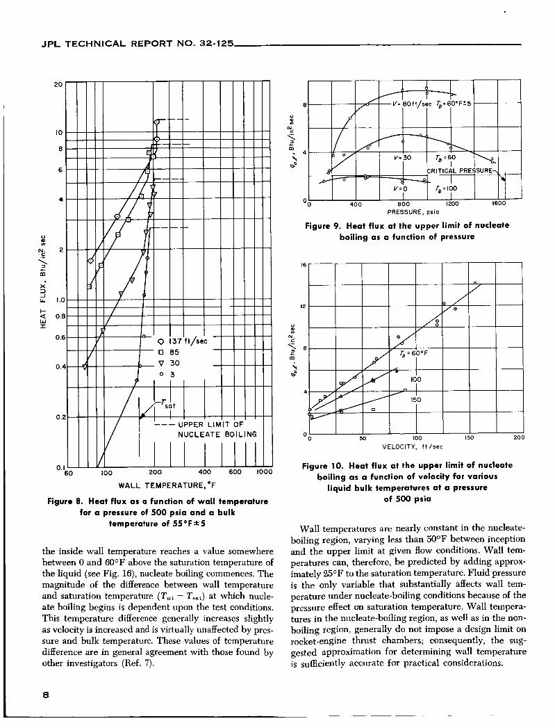
Figure 8. Heat flux as a function of wall temperature for a pressure of 500 psia and a bulk
temperature of 5 5 O F * 5
the inside wall temperature reaches a value somewhere between 0 and 60°F above the saturation temperature of the liquid (see Fig. 16), nucleate boiling commences. The magnitude of the difference between wall temperature and saturation temperature (Ttui - T,,,) at which nucle- ate boiling begins is dependent upon the test conditions. This temperature difference generally increases slightly as velocity is increased and is virtually unaffected by pres- sure and bulk temperature. These values of temperature difference are in general agreement with those found by other investigators (Ref. 7).
8
PRESSURE, psi0
Figure 9. Heat flux at the upper limit of nucleate boiling as a function of pressure
VELOCITY, f t /sec
Figure 10. Heat flux at the upper limit of nucleate boiling a s a function of velocity for various
liquid bulk temperatures at a pressure of 500 psia
Wall temperatures are nearly constant in the nucleate- boiling region, varying less than 5O0F between inception and the upper limit at given flow conditions. Wall tem- peratures can, therefore, be predicted by adding approx- imately 2 5 O F to the saturation temperature. Fluid pressure is the only variable that substantially affects wall tem- perature under nucleate-boiling conditions because of the pressure effect on saturation temperature. Wall tempera- tures in the nucleate-boiling region, as well as in the non- boiling region, generally do not impose a design limit on rocket-engine thrust chambers; consequently, the sug- gested approximation for determining wall temperature is sufficiently accurate for practical considerations.

I
JPL TECHNICAL REPORT NO. 32-125
D. Upper Limit of Nucleate Boiling
The heat flux at the upper limit of nucleate boiling q.I is of primary interest for the design of rocket-engine coolant passages because of the sudden large increase in wall temperature associated with the transition from nucleate boiling to film boiling. It was necessary to deter- mine experimentally the relationship of qUl to the vari- ables p, V, and T,,, since no general method of predicting qut is available. During the tests the transition to film boiling under all test conditions, except those at 10oO psia and above, resulted in tube failure before the heat flux could be reduced. At these higher pressures, the heat- transfer coefficient of the vapor film is sufficient to sup- port a heat flux at a wall temperature below failure limits. Therefore, the application of electrical power to the test section could be terminated before tube failure occurred.
In Fig. 9, qut is plotted vs pressure for given values of bulk temperature and velocity. At the two higher veloc- ities shown (80 ft/sec and 30 ft/sec) the maximum value of 4.1 was obtained at a pressure of about 900 psia, or approximately 5,5% of the critical pressure of 1657 psia. At zero velocity the peak value of 4.1 was observed to occur at about 500 psia, or approximately 30% of critical pressure. Cichelli and Bonilla (Ref. 8) also found the peak value of q.2 for several liquids with zero velocity to be approximately 30% of the critical pressure of the fluid.
LIOUID BULK TEMPERATURE,~F
Figure 11. Heat flux at the upper limit of nucleate boiling a s a function of liquid bulk temperature
for various velocities at a pressure of 500 psia
Nucleate boiling cannot exist above the critical pressure. Therefore, the heat flux measured for the test at 1820 psi is not quz but a heat flux at which the wall temperature exceeded 7W°F (see Fig. 7).
The effect of velocity on qUl is shown in Fig. 10, where it may be observed that 4.1 increases linearly with veloc- ity. The slopes of the curves are found to be dependent on liquid bulk temperature.
Figure 11 shows the effect of liquid bulk temperature on values of qut for velocities of 0, 30, and 60 ft/sec at a pressure of 500 psi. Values of qUl were found to decrease linearly with increasing bulk temperature to virtually a common value at the saturation temperature (160OF at a pressure of 500 psia). Bulk-temperature effects on 9.1 are more pronounced at the higher velocities.
An interpolation equation has been derived for com- puting 4.r from the experimental results:
(8) qui = [ 1 - 0.168(%)] [1.85
+ (0.0083 -I- 7.0 X 10⁻⁴V) Atsub]
The comparison of experimental values of q.1 with those obtained from Eq. 8 for the same conditions is shown in Fig. 17. Most of the experimental data lie within *20% of this equation. It should be emphasized that Eq. 8 was established from the best fit of experimental data rather than from a fundamental heat-transfer consideration.
In Table 1 the experimental values of 9.1 are listed for each condition of pressure, velocity, and bulk tempera- ture tested.
E. Total Heat Load
The capability of a coolant to accept the total heat load of a given size engine is dependent upon its specific heat, the difference between saturation temperature and coolant inlet temperature to the thrust chamber, propel- lant mixture ratio, and propellant combination. Compari- sons of various propellant combinations, including NH,-RFNA and NH,-0,, for arbitrary given conditions of a 50,000-lb-thrust engine are shown in Ref. 1. The abil- ity of the ammonia systems, using ammonia as the cool- ant, to accept the total heat load is marginal compared to some of the other systems, such as RFNA-UDMH with RFNA as the coolant, Corporal fuel-SFNA with Corporal
9

JPL TECHNICAL REPORT NO. 32-125
TEMPERATURE, O F
Figure 12. Viscosity of ammonia as a function of temperature and pressure
0 70
~ 0.66
> k a
0 3 0.58 a
0.62
U
w cn
05_%0 -20 0 20 40 60 80 100 120 140 TEMPERATURE, O F
Figure 13. Specific gravity of ammonia as a function of temperature
lL
Q
m
a
0 t a
> c
I-
W I
0 W
cn
1.4
1.3
12
1.1
‘ 0 TEMPERATURE, OF
Figure 14. Specific heat of ammonia as a function of temperature
1 0
~~ ~-
t
JPL TECHNICAL REPORT NO. 32-125
Velocity f t / H C
32.0 31.6 30.0 30.0 30.0 30.0 29.5
fuel as the coolant, DETA-SFNA with DETA as the cool- ant, and JP-3-N,04 with JP-3 as the coolant. It is of inter- est to note, however, that at a temperature of lW0F the specific heat of ammonia is 1.17 Btu/lb OF, which is high
Pressure pria
495 500 500 494 490 478 504
Figure 15. Thermal conductivity of ammonia os a function of temperature
484 38.0 8.03 490 58.0 7.01 484 65.0 6.69 497 99.0 5.00 492 101.0 4.90 502 154.0 4.16
206 73.0 3.75 352 59.0 6.90 496 63.0 8.45 516 58.0 9.12 530 66.5 7.23 775 60.0 9.30
1005 61.0 9.52
1215 68.0 8.96 ~ 1020 70.0 8.98
1000
800
6 00
400
200
0 01 .- n
100 I)
w IY a 60 IY 0 5 40
g 80
2 0
‘0-25 0 25 50 7 5 100 125 150
Table 1. Values of qrcl
T r (outlet) OF
22.5 27.5 76.0
100.5 101.0 149.0 152.0
~~
q* J
Btu/in? SIX
5.64 5.38 4.76 3.41 3.50 2.29 2.08
30.0 30.0 30.0 32.5 30.0 31.1 32.9 30.0 25.4 27.5
1 70 170 300 240 794 954
1025 1174 1555 1820
66.0 62.0 67.0 76.5 80.0 67.0 63.0 77.0 63.0 75.0
2.53 2.32 3.88 4.72 4.95 5.50 5.46 4.77 4.50 4.1 1
60.0 63.0 61.7 56.0 60.0 55.2
89.0 81.7 87.0 84.0 84.5 81.6 82.7 80.6 81.6
3.0 3.0
10.0 15.2 42.2 82.3 97.2 98.5
121.0 124.0 127.5 137.0 156.0
494 504 499 486 51 8 504 518 500 500 500 475 516 500
158.0 140.0 75.0 71.0 77.0
108.0 65.5
124.5 53.5 57.5 67.5 58.0 65.0
1.73 2.41 3.12 3.52 5.36 5.82 8.29 3.42
10.60 10.21 12.20 11.64 14.30
Heat flux at which the wall temperature exceeded 700°F.
compared to 0.42 Btu/lb O F for RFNA, 0.50 Btu/lb O F for Corporal fuel, 0.435 for JP-3, 0.393 for N,O,, and 0.744 for N,H,. The comparatively low saturation tem- perature of NH, imposes a restriction on its cooling capa- bility and offsets the high specific heat.
11

JPL TECHNICAL REPORT NO. 32-125
12
/ g / /
{I - 0. I68 [ (P - 530)/530]*}[1.85 + (O.O083+ 7.0 X 10⁻⁴V)A lSub]
Figure 17. Comparison of experimental values of qUl with Eq. ( 8 )
JPL TECHNICAL REPORT NO. 32-125
Vll. CONCLUSIONS
The results from this experimental heat-transfer inves- tigation showed that the convective heat-transfer coeffi- cient of ammonia in the turbulent-flow nonboiling region could be predicted within +20!% by the Sieder-Tate equation when the physical properties were evaluated at the liquid-bulk temperature and a correction Was made for the viscosity distribution across the boundary layer.
The wall temperature at the inception of nucleate boil- ing is equal to the saturation temperature plus about %OF. Once nucleate boiling was established, the wall temperature remained nearly constant with increasing heat flux until qut was reached. Values of qUz were repro- ducible and showed trends as a function of pressure, velocity, and liquid bulk temperature typical of other liquids. At a given pressure, the value of 9.1 increased with increasing velocity and decreased with increasing bulk temperature to an apparent common value at the
saturation temperature. As a function of pressure, values of qUl were a maximum at about 55% of the critical pres- sure under flow conditions; whereas, at zero velocity, qUl reached a maximum at about 30% of the critical pressure.
The capability of ammonia as a regenerative coolant for rocket engines is dependent upon its ability to accept local heat fluxes (which is established by 4.1) and its ability to accept total heat loads of the entire thrust cham- ber. For comparative purposes, the values of qnl of vari- ous propellants are given at a pressure of 300 psia, a velocity of 30 ft/sec, and a liquid bulk temperature of 1 0 0 O F ; they are 2.5 for NH,, 4.5 for JP3, 4.6 for Nz04, 6.8 for RFNA, 8.1 for Corporal fuel, and 12.4 for N,H4. Consequently, the local cooling capability of ammonia at these conditions is comparatively low. The total heat-load cooling capability of NH, is limited by the low saturation temperature, even though it has a high specific heat value.
NOMENCLATURE
A area, in.' c,, specific heat at constant pressure, Btu/lb O F
D diameter of tube, in.
E voltage, v h heat-transfer coefficient, Btu/sec in.' O F
I current, amp R thermal conductivity, Btu/sec in. O F ,
L length of test section, in. M molecular weight
except as noted
Nu Nusselt number = R h D, (dimensionless)
Pr Prandtl number = PC (dimensionless) b
q heat flux, Btu/in.2 sec r radius,in.
R resistance, Q
pD.V P
Re Reynolds number = (dimensionless)
S specific gravity T temperature, O F
t wall thickness, in. ZJ velocity, ft/sec
i weight flow rate, lb/sec A T temperature difference, O F
p viscosity, lb/in. sec, except as noted
p density, lb/in.3
13
JPL TECHNICAL REPORT NO. 32-125
NOMENCLATURE (Cont’dl
Subscripts saturation condition
B liquid bulk condition
i inner
outer
s l l b subcooling (i.e., saturation condition minus bulk condition)
u z upper limit of nucleate boiling
8 surface normal to heat flow wall condition
REFERENCES
1. Bartz, D. R., Factors Which Influence the Suitability of Liquid Propellants as Rocket Mofor Regenerative Coolants, Memo No. 20-1 39, Jet Propulsion Laboratory, Pasa- dena, December 28, 1956.
2. Massier, P. F., A Forced Convection and Nucleate Boiling Heat-Transfer Test Appa- ratus, Technical Report No. 32-47, Jet Propulsion Laboratory, Pasadena, February 3, 1961.
3. McAdams, W. H., Heat Transmission, McGraw Hill Book Co., Chapter VII, p. 168, 1942.
4. Perry, John H., Chemical Engineers’ Handbook, Second Edition, 1941, p. 962.
5. Kardos, A., “Die Warmenleitfahigkeit verschiedener Flussigkeiten,” Zeitschrift fur die gesclmte Kalte-lndustrie, Vol. 41, No. 2 (1 934).
6. Hartnett, J. P., “Experimental Determination of the Thermal-Entrance Length for the Flow of Water and of Oil in Circular Pipes,” ASME Transactions, Vol. 77, p. 121 1, November 1955.
7. Reinhardt, T. F., Potter, R. L., and Moore, F. M., “Heat Transfer Properties of Anhy- drous Ammonia,” OASD Research and Development, p. 85, Liquid Propellants Symposium, March 27-28, 1957.
8. Cichelli, M. T., and Bonilla, C. F., Transactions of the American Institute of Chemical Engineers, Vol. 41, p. 755, 1945.
9. Carmichael, L. T., and Sage, B. H., “Viscosity of Liquid Ammonia at High Pressure,” Industrial and Engineering Chemistry, VOI. 44, Pt. II, pp. 2728-32, 1952.
10. Tables of Thermodynamic Properties of Ammonia, National Bureau of Standards Circular No. 142, April 19, 1923.
14
-