Embed Size (px)
Citation preview
NASA Technical Memorandum 107071 AIM-93-4 170
A
Nuclear Thermal Rocket/Vehicle Design Options for Future NASA Missions to the Moon and Mars
Stanley K. Borowski and Robert R. Corban Lewis Research Center Cleveland, Ohio
Melissa L. McGuire Analex Corporation Brook Park, Ohio
Erik G. Beke University of Dayton
\ Dayton, Ohio
Prepared for the Space Programs and Technologies Conference and Exhibit sponsored by the American Institute of Aeronautics and Astronautics Huntsville, Alabama, September 21-23, 1993
J
National A&mautics and spacehhninistration
p _ ,
( N A S A - T M - 1 0 7 0 7 1 ) NUCLEAR THERMAL R O C K E T / W E H I C L E OESXGN O P T I O N S FOR FUTURE N A S A MISSIONS TO T H E MOON A N D MARS ( N A S A . L e w i s Research Center ) 39 p
N96-11955
Uncl as
G 3 / 2 0 0069844

.
ABSTRACT
NUCLEAR MERMAL ROCKETNEHICLE DESIGN OPTIONS m
FUTURE NASA MISSIONS TO THE MOON AND MARS
Stanley K. Borowski’ and Robert R. Corban*’ Nuclear Propulsion Off ice
NASA Lewis Research Center 21 000 Brookpark Road
Cleveland, OH 44135
Melissa L. McGuire” Advanced Space Analysis Office
Analex Corporation 3001 Aerospace Parkway
Brook Park, OH 44145
Erik G. Beke Mechanical and Aerospace Engineering
University of Dayton 300 College Park
Dayton, OH 45469
The nuclear thermal rocket (NTR) provides a unique propulsion capability to planners/designers of future human exploration missions to the Moon and Mars. In addition to its high specific impulse (-850-1000 s) and engine thrust-to-weight ratio (-3-10), the NTR can also be configured as a “dual mode” system capable of generating electrical power for space- craft environmental systems, communications, and enhanced stage operations (e.g., refrigeration for long-term liquid hydrogen storage). At present the Nuclear Propulsion Office (NPO) is examining a variety of mission applications for the NTR ranging from an expendable, “single burn” trans-lunar injection (TLI) stage for NASA’s “First Lunar Outpost” (FLO) mission to all propulsive, “multi-burn,” NTR-powered spacecraft supporting a “split cargo/piloted sprint“ Mars mission architecture. Each application results in a particular set of requirements in areas such as the number of engines and their respective thrust levels, restart capability, fuel operating temperature and lifetime, cryofluid storage and stage size. Two solid core NTR concepts are examined--one based on NERVA (Nuclear Engine for Rocket Vehicle
Application) - derivative reactor (NDR) technology, and a second concept which utilizes a ternary carbide “twisted ribbon” fuel form developed by the Commonwealth of Independent States (CIS). The NDR and CIS concepts have an established technology database involving significant nuclear testing at or near representative operating conditions. Integrated systems and mission studies indicate that clusters of two to four 15 to 25 klbf NDR or CIS engines are sufficient for most of the lunar and Mars mission scenarios currently under consideration. This paper provides descriptions and performance characteristics for the NDR and CIS concepts, summarizes NASA’s First Lunar Outpost and Mars mission scenarios, and describes characteristics for representative cargo and piloted vehicles compatible with a reference 240 t-class heavy lift launch vehicle (HLLV) and smaller 120 t HLLV option. Attractive performance characteristics and “high leverage” technologies associated with both the engine and stage are identified, and supporting parametric sensitivity data is provided. The potential for “commonality” of engine and stage components to satisfy a broad range of lunar and Mars missions is also discussed.
____________________________ ‘Ph.D./Nuclear Engineering, Member AlAA “Aerospace Engineer, Member AlAA
In May 1991, the Synthesis Group issued its report1 entitled “America at the Threshold: America’s Space Exploration Initiative,” which outlined four different approaches or architectures for lunar/Mars exploration, identified key technology development areas and included recommendations for effectively implementing a Space Exploration Initiative (SEI) for this country. Several important technical strategies were also advanced that affected space transportation system (STS) design. These included use of (1) a heavy lift launch vehicle to limit on-orbit assembly; (2) a split mission strategy (where cargo and crew fly on separate missions); (3) pre-deployed and verified “turn-key” habitats; (4) chemical and nuclear thermal propulsion for lunar and Mars missions, respectively; (5) direct entry of returning crews to Earth’s surface; (6) lunar missions as a ”testbed” for Mars; and (7) to the extent possible, common systems for lunar and Mars missions.
Since that time, the various NASA Centers, under the direction of the Exploration Program Office (ExPO), having been assessing the scientific and technical merits of the proposed Synthesis Group architecture. During FY92, NASA’s “in-house” study efforts were focused on returning humans to the Moon. In its report, the Synthesis Group recommended a piloted mission profile based on the lunar orbit rendezvous (LOR) technique successfully used in the Apollo Program. The proposed scenario utilized a separate “in-space’’ lunar transfer vehicle (LTV) and lunar excursion vehicle (LEV) for surface descent and return. The spacecraft components would be launched on a 150 1-class HLLV. Following its review2 of the Synthesis Group architectures, the ExPO adopted a “lunar direct” mission profile for its FLO mission. The design reference mission utilized an expendable, cryogenic TLI stage along with a single integrated LTV/LEV design which performed both “in- space“ transfer and lunar landing. Because the entire piloted vehicle (which includes the crew module and Earth return stage) is transported to the lunar surface, the lunar direct mode is very sensitive to the crew module mass and the choice of propellant for the ascent/Earth return stage. With a storable propellant option selected by ExPO, a single launch 250 t-class HLLV was required for the FLO mission architecture.
In FY93, NASA’s emphasis shifted away from FLO to Mars exploration. ‘An intercenter Mars Study
2
Team was organized by ExPO and tasked with assessing the requirements for a piloted mission to Mars as early as 2010. A 2010 Mars landing is one of the most demanding mission opportunities over the 15-year synodic period and was selected to provide margin in the sizing of components for the Mars STS. A splitlsprint mission scenario was baselined and NTR propulsion was selected for all primary propulsion maneuvers. The selection of NTR propulsion is in keeping with the Synthesis Group report, which recommended the NTR as the “only prudent propulsion system for Mars transit.”l
.
After an initial assessment of the Mars Study Team results in October 1992, the reference Mars architecture was modified by ExPO to incorporate a “dual use” Mars aerobrake/descent shell and “in-situ” resource utilization in an effort to achieve a single launch Mars cargo and piloted mission capability with a 240 t-class HLLV. Using liquid hydrogen (LH2) brought from Earth, Martian carbon dioxide (C02) would be converted to liquid oxygen/liquid methane (LOX/CH4) propellant to fuel the ascent stage of the Mars excursion vehicle (MEV).3 A separate Earth return stage awaiting the crew in Mars orbit would also utilize a LOX/CH4 propulsion system to achieve some degree of hardware commonality. Crew return to Earth would be accomplished using an Earth crew return vehicle (ECRV) and a direct Earth entry similar to that used in the Apollo Program. The NTR would be used only for the trans-Mars injection (TMI) maneuver (see Table 1).
The use of aerobraking for Mars orbit capture (MOC) was rejected1 by the Synthesis Group for a variety of mission-, spacecraft design-, and safety- related issues. EXPO’S present acceptance of a “dual use” aerobrake/aerodescent shell is based primarily on the assumption that entry velocities at Mars for conjunction-class missions will be similar to that encountered during surface descent. This assumption neglects the piloted missions which will have substantially higher entry velocities, especially during those easier Mars mission opportunities where excess propellant margin is used to further reduce “1-way” transit times to periods as short as four months compared to the six-month reference mission transit time. Designing a “common” dual use aerobrake to accommodate these higher energy trajectories is expected to result in substantially heavier configurations than that assumed in this study.

Table 1. NTR Mars Mission Application Options
I I Mission Maneuvers
NTR Trans Trans Performs Mars Orbit Earth Return
Injection Capture
,Cargo Vehicles
Piloted Vehicles
Because the time and cost to develop the myriad of transportation system elements for both FLO and the reference Mars architecture are anticipated to be signiJcant, the Nuclear Propulsion Office (NPO) has been examining 4.5 the rationale and benefits of an integrated MoonlMars exploration strategy. In this approach, a common, modular NTR-based STS would be developed which uses "standardized" engine and stage components in a
"building block" fashion to configure a wide variety of single and multi-engine lunar and Mars vehicles (see Figure 1). The modular approach has a number of attractive features which include enhanced mission flexibility and safety, simplified vehicle design and assembly, and reduced developmentlprocurement costs through standardization of the "fewest number" of components.
Lunar
ROUUM. Pll0t.d awl.
IMLEO - 2181
20iO"AII Up" P I IOM V O h W
PAYLOAD
"MODULAR" LH2 TANKS (10mdla.X 1%)
LUNAR NTR "CORE" STAGE w/CON ICAL LH2 TANK ((Om dlo. X 29m)
PROPULSION MODULE (75 klbl NDR 0 925s
Fig. 1. Modular LunarlMars NTR Vehicle Configurations
3

In keeping with NPOs integrated MoonlMars mission approach, and the premise that it is not commonality alone but commonality of the fewest number of new systems that will result in an affordable exploration program, the NPO has continued to examine the reference Mars architecture as well as other Mars mission profiles (see Table 1) which reduce mission risk and more effectively utilize the NTR’s improved propulsion efficiency and power generation capability as well. This paper describes results of system/mission studies used to determine engine and stage characteristics best suited for both lunar and Mars mission applications. Included in the paper are vehicle configurations compatible, from a mass and volume standpoint, with a reference 240 t HLLV and a smaller 120 t to low Earth orbit (LEO) option. The paper first describes the NDR and CIS solid core NTR concepts and provides scaling data for these engine systems in the 15 to 75 klbf thrust range. Next, NASA’s reference lunar and Mars scenarios are reviewed, mission and transportation system ground rules and assumptions are summarized, and representative NTR vehicles are presented. Parametric data provides the basis for identifying the modular engine and stage components recommended in this paper. Finally, a summary of our findings and the conclusions reached in this study are presented.
CONCFPT OPTION3SCAI ING
The NTR has been identified in both NASA’s “90- Day Study Report”6 and the Synthesis Group Report1 as a critical technology enabling minimum trip timdminimum IMLEO missions to Mars. The feasibility of using low molecular weight LH2 as both a reactor coolant and propellant was convincingly demonstrated in the United States during the Rover/NERVA (Nuclear Engine for Rocket Vehicle Application) nuclear rocket programs.7 From 1955 until the program was stopped in 1973, a total of twenty rocket reactors were designed, built and tested. These reactor/integrated engine system tests demonstrated the power, thrust, and hydrogen exhaust temperature levels, together with the burn durations and restart capability, required for a Mars mission. The RoverlNERVA program costs were estimated at $1.4 billion. Escalated to 1992 dollars, this technology represents an investment of -$lo billion.
Approximately four years after the start of the NERVA program, a nuclear rocket technology program was initiated in the former Soviet Union8
known today as the Commonwealth of Independent States (CIS). The CIS has conducted extensive nuclear and non-nuclear subsystems tests, including fuel element and reactor tests at the Semipalatinsk facility in Kazakhstang. Although no engine system tests were conducted, a high temperature ternary carbide fuel element was developed capable of producing hydrogen exhaust temperatures in excess of 3000 K. The CIS also claims 250,000 man-years of NTR design and test experience over an -30-year period. A substantial test infrastructure continues to exist today in the CIS making a joint US/CIS program9 a potentially cost-effective approach to developing this important technology.
Three thermal and one fast solid core NTR concepts are currently being studied8 by NPO and its industry contractors for potential development and use in future NASA exploration missions. Reactor analysis and engine design work is being performed by the industry contractor teamslo.11 of (1) Rocketdyne and Westinghouse on the NERVA- derivative reactor (NDR) concept, (2) Pratt and Whitney and Babcock and Wilcox (saw) on the CERMET fast reactor, (3) Aerojet and B&W on a particle bed reactor (PBR), and (4) Aerojet, Energopool and B&W on a CIS engine concept using the “twisted ribbon” ternary carbide fuel form. Of the four concepts under consideration, only the NDR and CIS concepts have undergone significant nuclear testing and “proof-of-concept’’ validation. They will be the principle focus of discussion and comparison in this paper.
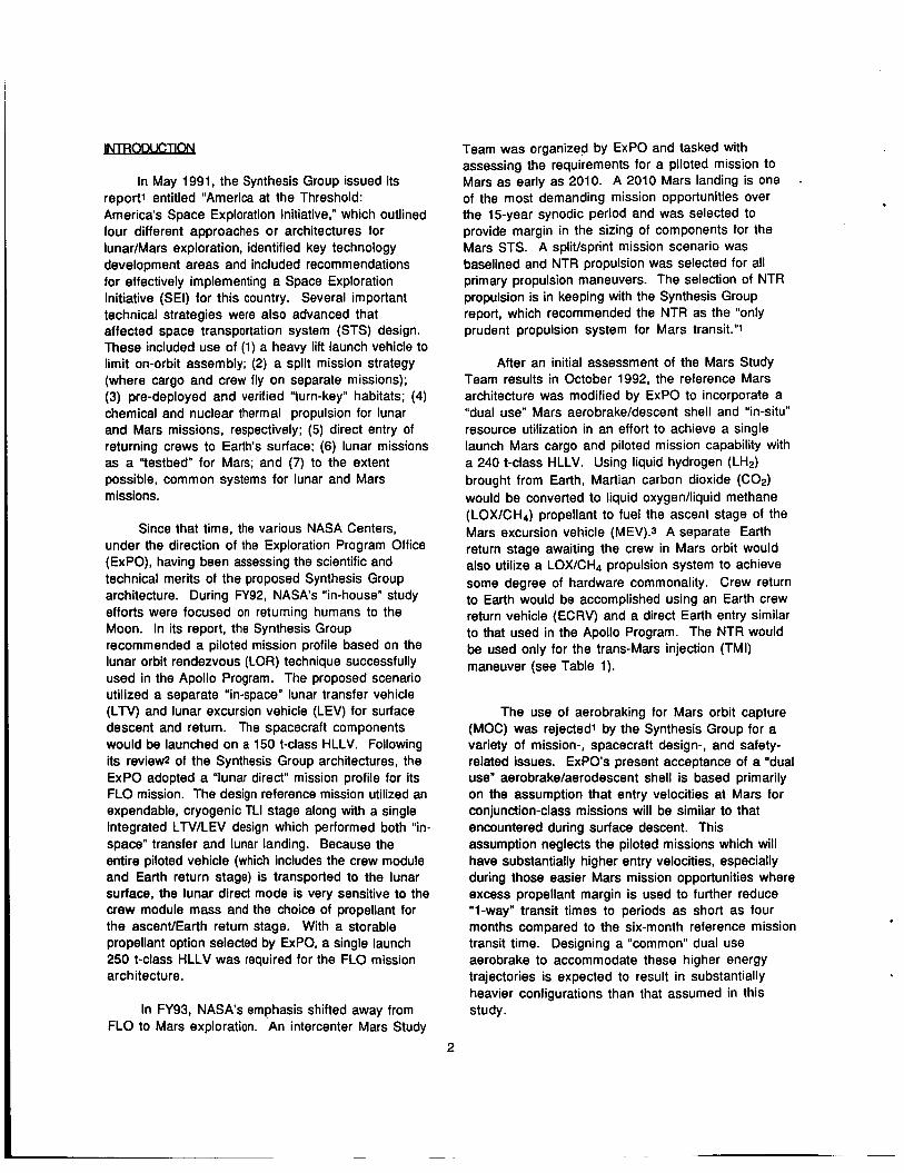
The NDR is a graphite moderated, homogeneous NTR concept in which the fuel and neutron moderating materials are intermixed. The NDR design uses a hexagonally-shaped fuel element (0.75” across the flats), which is capable of producing -0.9 to 1.2 megawatts of thermal power (MWt) with a 52“ long fuel element, and -0.6 to 0.8 MWt with a 35” long element (see Figure 2). Each fuel element has 19 axial coolant channels, which along with the outer element surfaces, are coated with zirconium carbide (ZrC) to reduce hydrogedgraphite reactions. A “2-pass’’ regeneratively-cooled, tie-tube assembly Supports from 2 to 6 fuel elements forming a fuel bundle (shown in Figure 2). Specifying the engine thrust level, hydrogen exhaust temperature (or equivalent
4
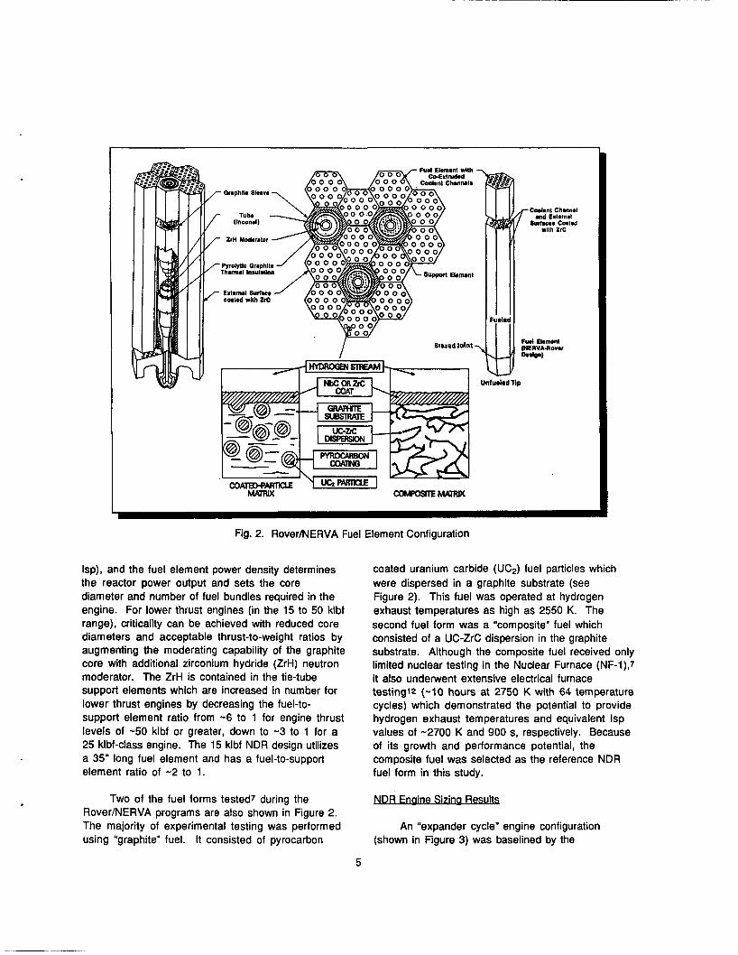
Fig. 2. RoverMERVA Fuel Element Configuration
Coolant Channel and Lxlemal
Sudans Coalad
Unfurled Tlp
Isp), and the fuel element power density determines the reactor power output and sets the core diameter and number of fuel bundles required in the engine. For lower thrust engines (in the 15 to 50 klbt range), criticality can be achieved with reduced core diameters and acceptable thrust-to-weight ratios by augmenting the moderating capability of the graphite core with additional zirconium hydride (ZrH) neutron moderator. The ZrH is contained in the tie-tube support elements which are increased in number for lower thrust engines by decreasing the fuel-to- support element ratio from -6 to 1 for engine thrust levels of -50 klbf or greater, down to -3 to 1 for a 25 klbf-class engine. The 15 klbf NDR design utilizes a 35” long fuel element and has a fuel-to-support element ratio of -2 to 1.
coated uranium carbide (UC2) fuel particles which were dispersed in a graphite substrate (see Figure 2). This fuel was operated at hydrogen exhaust temperatures as high as 2550 K. The second fuel form was a “composite” fuel which consisted of a UC-ZrC dispersion in the graphite substrate. Although the composite fuel received only limited nuclear testing in the Nuclear Furnace (NF-l),7 it also underwent extensive electrical furnace testing12 (-10 hours at 2750 K with 64 temperature cycles) which demonstrated the potential to provide hydrogen exhaust temperatures and equivalent Isp values of -2700 K and 900 s, respectively. Because of its growth and performance potential, the composite fuel was selected as the reference NDR fuel form in this study.
NDR FnameSmg Results . . . Two of the fuel forms tested7 during the
Rover/NERVA programs are also shown in Figure 2. The majority of experimental testing was performed using “graphite” fuel. It consisted of pyrocarbon
An “expander cycle” engine configuration (shown in Figure 3) was baselined by the
5

Fig. 3. Schematic of a Dual Turbopump Expander Cycle NDR Engine
RocketdyneiWestinghouse industry team in which the turbine drive gas is routed to twin turbopumps (used for redundancy and improved system reliability) and then through the reactor core, allowing the entire propellant flow to be heated to design conditions. Hydrogen flowing from the pumps would be split with a portion being used to cool the nozzle, reflector, control rods and internal dome shield, and the remainder going to the core support tie tubes (not shown in Figure 3) for cooling and providing the necessary turbine drive power.
To achieve a composite fuel specific impulse design goal of -900 s (-870 s for graphite fuel at 2550 K) in a 25 klbf-class engine with a length limit of -6 m,13
a chamber pressure of -785 psia, nozzle area
expansion ratio of 200 to 1, and a 11 0% length optimum contour Rao nozzle was selected. These same pressure and nozzle conditions were maintained for engine point designs at the 15, 50, and 75 klbf thrust levels. Figure 4 shows engine weight scaling data for NDR systems. Included in the weight estimate of each engine is an internal radiation shield comprised of boron-carbide aluminum-titanium hydride (BATH), used to limit neutron and gamma radiation heating of the turbomachinery and the LH2 propellant. The relative size of the 25, 50 and 75 klbf-class composite fuel NDR engines is shown in Figure 5. Not shown is the 15 klbf NDR design which has an overall length of -4.7 m and a nozzle exit diameter of -1.4 m.
0 10 20 30 40 5 0 6 0 70 80 Single Engine Thrust (klbf)
Fig. 4. NDWCIS Engine Weight Scaling
6
r
4
1 7.66 ni
- I I-- 2.44 m --; !-- . 2.99 in--- .;
25 klbf 50 klbf 7s klbf
Fig. 5. Relative Size of Dual Turbopump NDR Engines
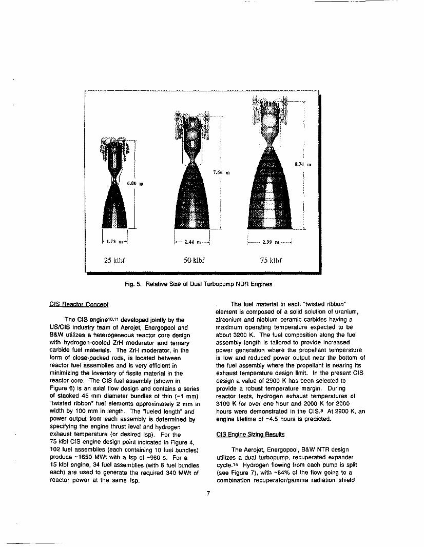
The CIS enginelopll developed jointly by the US/CIS industry team of Aerojet, Energopool and B&W utilizes a heterogeneous reactor core design with hydrogen-cooled ZrH moderator and ternary carbide fuel materials. The ZrH moderator, in the form of close-packed rods, is located between reactor fuel assemblies and is very efficient in minimizing the inventory of fissile material in the reactor core. The CIS fuel assembly (shown in Figure 6) is an axial flow design and contains a series of stacked 45 mm diameter bundles of thin (-1 mm) “twisted ribbon” fuel elements approximately 2 mm in width by 100 mm in length. The “fueled length” and power output from each assembly is determined by specifying the engine thrust level and hydrogen exhaust temperature (or desired Isp). For the 75 klbf CIS engine design point indicated in Figure 4, 102 fuel assemblies (each containing 10 fuel bundles) produce -1650 MWt with a Isp of -960 s. For a 15 klbf engine, 34 fuel assemblies (with 6 fuel bundles each) are used to generate the required 340 MWt of reactor power at the same Isp.
The fuel material in each “twisted ribbon” element is composed of a solid solution of uranium, zirconium and niobium ceramic carbides having a maximum operating temperature expected to be about 3200 K. The fuel composition along the fuel assembly length is tailored to provide increased power generation where the propellant temperature is low and reduced power output near the bottom of the fuel assembly where the propellant is nearing its exhaust temperature design limit. In the present CIS design a value of 2900 K has been selected to provide a robust temperature margin. During reactor tests, hydrogen exhaust temperatures of 3100 K for over one hour and 2000 K for 2000 hours were demonstrated in the CIS3 At 2900 K, an engine lifetime of -4.5 hours is predicted.
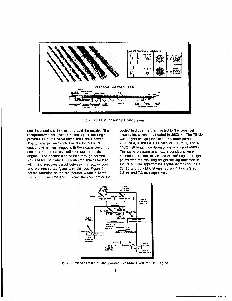
The Aerojet, Energopool, B&W NTR design utilizes a dual turbopump, recuperated expander cycle.14 Hydrogen flowing from each pump is split (see Figure 7), with -84% of the flow going to a com bination recuperator/gamma radiation shield
7
~~
Fig. 6. CIS Fuel Assembly Configuration
and the remaining 16% used to cool the nozzle. The recuperator/shield, located at the top of the engine, provides all of the necessary turbine drive power. The turbine exhaust cools the reactor pressure vessel and is then merged with the nozzle coolant to cool the moderator and reflector regions of the engine. The coolant then passes through borated ZrH and lithium hydride (LiH) neutron shields located within the pressure vessel between the reactor core and the recuperator/gamma shield (see Figure 7), before returning to the recuperator where it heats the pump discharge flow. Exiting the recuperator the
cooled hydrogen is then routed to the core fuel assemblies where it is heated to 2900 K. The 75 klbf CIS engine design point has a chamber pressure of 2000 psia, a nozzle area ratio of 300 to 1, and a 110% bell length nozzle resulting in a Isp of -960 s. The same pressure and nozzle conditions were maintained for the 15, 25 and 50 klbf engine design points with the resulting weight scaling indicated in Figure 4. The approximate engine lengths for the 15, 25, 50 and 75 klbf CIS engines are 4.3 m, 5.2 m. 6.5 m, and 7.6 m, respectively.
I 1166R
2719 psla i(~snilo*
1165R 2719 PSIS
"I IIY 9 L . U c
4 4 1156 R
n l o D.I.
RATOR 1 1 REFLECTOR ]
ahs (0.3%) PRESS. VESSEL
M A
Fig. 7. Flow Schematic of Recuperated Expander Cycle for CIS Engine
8

A large number of options for expanding lunar exploration beyond Apollo were studied1 5 and proposed by NASA during the 1960’s as possible follow-on activities in a “post-Apollo” program. Since 1987, NASA has spent considerable time assessing the human operations and surface support requirements needed to return humans to the Moon at levels ranging from short duration expeditionary landings to human-tended outposts, and ultimately to centralized bases16 supporting a substantial permanent human presence. Following its review of the Synthesis Group architectures, a split mission “lunar campsite” scenario was adopted by EXPO for the FLO mission. On the initial cargo mission, a pre- integrated, reusable habitat module is delivered intact on a common lander vehicle which performs both lunar orbit insertion and descent. The habitat provides facilities to support a crew of four for 45 Earth days (a lunar day, night, day cycle). Once the operational functions of the outpost have been verified, the crew begins their journey using a “lunar direct” mission profile which provides “global access” to the Moon and an “anytime orbit“ capability for the crew. On the piloted mission, the habitat module is replaced by a lunar ascenffEarth return stage with a crew module used at mission end for direct Earth entry. Both the cargo and piloted missions are launched individually on a single 250 t-class HLLV.
The main elements of the FLO space transportation system are shown in Figure 8. They consist of a TLI stage, a common lunar lander, an Earth return stage, and a crew module, all of which are expended during the course of the mission. In the “cargo only” mode, the return stage and crew module would be replaced by an equivalent amount of cargo which could include such items as surface habitats, crew consumables, rovers and science equipment. The total mass of the common lander with its cryogenic propellant load, payload and TLI stage adaptor is -96 t. The reference chemical TLI stage uses a single J-2s engine (lsp=436 s) with a thrust of 265 klbf for primary propulsion and a monopropellant hydrazine (lsp=237 s) reaction control system (RCS) for attitude control and stabilization. Aluminum alloy is utilized for structures and tankage. The stage contains -133.5 t of LOX/LH2 propellant and has a dry mass of -21.5t.
An “alternative” NTR-powered TLI stage, also shown in Figure 8, was proposed by NPO during its “Fast Track Study”13. It uses three 25 klbf engines which operate at a lsp=900 s and provides a total thrust of 75 klbf. Although the stage is -4 m longer than the chemical system, it is -54 t lighter than its chemical counterpart. The propellant and stage inert weights are -67 t and -34 t, respectively. Following a 28 minute TLI burn and an appropriate cooldown period, the piloted FLO vehicle and NTR stage separate with the piloted vehicle continuing on its nominal mission. The NTR stage executes a retargeting/disposal maneuver with its RCS system to perform a ”trailing edge” lunar swingby. The resulting lunar gravity assist is used to deliver the “spent” NTR stage to a long-lived (-105 year) heliocentric orbit with minimal risk of Earth reencounter.
FLO MissionflransDortat ion Svstem Bound Rules and AssumDtions
Key ground rules and assumptions used in determining the characteristics of the lunar NTR TLI stage are summarized in Table 2, which provides details on payload mass, velocity change (AV) requirements, primary and auxiliary propulsion, tankage and contingency factors. For the FLO mission, a “single burn” Earth departure scenario was baselined. In addition to the primary TLI AV maneuver performed by the NTR system, the TLI stage also executes mid-course correction (MCC) and retargeting maneuvers using a storable propellant RCS system.
The Fast Track Study13 used graphite-fuel NDR technology almost exclusively, although performance using composite fuel was also examined. In this study, the composite and ternary carbide fuel forms are featured and compared. Biological external disk shields were baselined for the piloted FLO mission with shield weights being scaled with the thrust/power level of the stage. Allowances for flight performance reserve, post-burn reactor cool down, and tank trapped propellant residuals were also accounted for in estimating the total propellant requirements for the mission.
9

Fig. 8. FLO Space Transportation System Elements
Cargo 36 t
53 Crew Module
ReturnStage=31t Payload= 5 t
Total = 36 t
+
Return Stage Storable Propellants
(Cry0 Optional) \ \
Surface Habitat = 34 t Consumables= 2 t
/
Common Lander w/ Cryogenic Propellants Total=60t (wEL1 Stage Adapter)
"Reference" Chemical TLI Stage
Diameter = 10 m Length = 18 m
I TotalMass=155t 1
LOXLH2 Propellant
J-2s Engine (F = 265 klbf)
3 NDREngines- (each @ 25 klbf)
I I
"Alternative" NTR TLI Stage
Diameter = 10 m Length = 22 m
Total Mass = 101 t
LH2 Propellant
10
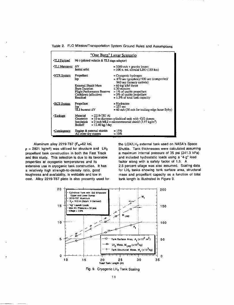
Table 2. FLO Missionflransportation System Ground Rules and Assumptions
"One Burn" Lunar Scenario *TLI Pavlollg 96 t (piloted vehicle & TLI stage adaptor)
*TLI Maneuver AV Initial orbit
= 3200 m/s + gravity losses = 100 n. mi. clrcular LEO (185 km)
*NTR Svsteq Propellant = Cryogenic hydrogen ISP = 870 sec (graphite)/ 900 sec (composite)/
External Shield Mass = 60 kg/ klbf thrust Bum Duration S 30 minutes Flight Performance Reserve = 1% of usable propellant Cooldown (effective) = 3% of usable pro ellant Residual = 1.5% of total tadcapacity
960 sec (ternary carbide)
*- Propellant
21 burnout AV =H drazine = 217 sec = 60 m/s (30 m/s for trailing edge lunar flyby)
0- Material = 2219-T87 AI Geometry Insulation Boiloff
= 10 m diameter cylindrical tank with d2/2 domes = 2 inch MLI + micrometeoroid shield (3.97 kg/m*) = 12.40 kg / day
Engine & external shields = 15% I *- All other drv masses = 10%
Aluminum alloy 221 9-T87 (Ft,=62 ksi, p = 2821 kg/m3) was utilized for structure and LH2 propellant tank construction in both the Fast Track and this study. This selection is due to its favorable properties at cryogenic temperatures and its extensive use in cryogenic tank construction. It has a relatively high strength-to-density ratio, good toughness and availability, is weldable and low in cost. Alloy 2219-T87 plate is also presently used for
the LOX/LH2 external tank used on NASA's Space Shuttle. Tank thicknesses were calculated assuming a maximum internal pressure of 35 psi (241.3 kPa) and included hydrostatic loads using a "4-9" load factor along with a safety factor of 1.5. A 2.5 percent ullage was also assumed. Scaling data for LH2 tanks showing tank surface area, structural mass and propellant capacity as a function of total tank length is illustrated in Figure 9.
20 200
15 150
10 100
5 50
0 0 10 15 20 25 30 35
Fig. 9. Cryogenic LH2 Tank Scaling
11
Total Tank Length (m)

Ground rules and assumptions on cryogenic LH2 storage used in this study are summarized in Table 3. A two inch helium-purged, multilayer insulation (MLI) system (at 50 layers per inch) was assumed for thermal protection of the NTR TLI stage LH2 tank. This insulation thickness exceeds the requirements for the short duration (I 8 hrs), “1- burn” FLO mission, as well as, the “ground hold” thermal protection requirements for “wet-launched’’ LH2 tanks (a minimum of 1.5 inches of helium-purged insulation).l7 Its use in the FLO mission would provide extra margin and verify the performance of thicker MLI blankets required for longer duration Mars and lunar missions. The installed density of the “2 inch MLI system” is -2.62 kglm2 and the resulting boiloff rate is -1.31 kglm2lmonth (based on an estimated heat flux of -0.22 W/m2 at a LEO sink temperature of - 240 K). Finally, a 0.5 mm sheet of aluminum (corresponding to -1.35 kg/m2) is included for micrometeoroid protection of the LH2 tank.
As the size of payloads delivered to the lunar surface increase, the benefits of a NTR lunar transfer stage become more apparent. A sizing analysis was performed during the Fast Track Study to determine attractive NTR enginektage configurations for the FLO mission. Figure 10 shows the IMLEO required to
deliver 96 t (the mass Of the current FLO piloted vehicle) to TLI conditions, as a function of engine thrust level for single and multi-engine stage designs. Each curve represents a “family of vehicles” which are similar in terms of the number of engines and the stage geometry (e.g., all LH2 tanks are cylindrical with 10 m diameters and 4212 ellipsoidal upper and lower domes). The configurations vary, however, with regard to the total length of the LH2 tank and the physical dimensions of the engine(s) used.
Figure 10 also shows that, for a given “total” thrust level, multiple engine configurations have a higher IMLEO. This is due in part to the buildup of inert weight from multiple engine components (e.g., pumps, lines and valves, shielding, etc.) in a “clustered” configuration, and also to the deterioration in the engine thrust-to-weight ratio for lower thrust NTR systems (shown in Figure 4). Each curve in Figure 10 also exhibits a distinct minimum in IMLEO. It is at this point that the optimum engine thrust level (with respect to IMLEO) is found. At higher thrust levels, or to the right of the optimum engine size, the propulsion system mass is excessive and leads to an increase in IMLEO despite the mass savings resulting from reduced gravity losses. Conversely, at the lower thrust levels, or to the left of the minimum IMLEO, reductions in propulsion system mass due to lower total thrust are offset by
Table 3. Ground Rules and Assumptions on LH2 Boiloffllhermal Protection System Weights
Parameter ; Heat Flux Scale Factors (applied to Lockheed Equation” in estimating boiloff) LEO Sink Temperature Mars Transit Temperature Mars Orbit Temperature Multi Laye! Insulation (MLI areal densit @ 50 layerskch & 25 IayersLIanket) Vapor-Cooled-Shield (VCS) areal density Reduced Heat Leak due to VCS
Refri erator S ecific Mass Variaton with eooling Capacity
Refrigerator Input Power Micrometeoroid Shield (- 0.5 mm sheet of Aluminum)
Plurrt orlrntrd tmperatures used In these analyses
3X for MLI At 1.2 inches 5X (for MLI At > 2 inches] Planet oriented: 240 K
170 K Planet oriented: 185 K
2.0 inch: 2.621 kg/m2 3.0 inch: 3.772 kg/m2 4.0 inch: 4.924 kglm2 1.952 kg/m2
35%
- 0.1 4 kWe/W refrig. 1.35 kg/m2
12

U C2 Particles in Graphite with ZrH Moderalor Augmentation 1.2 MWth per Fuel Element, Tc=2SS0 K, Isp=870 sec
- Composite (900 scc)
(t) /( mim) / (4 NTH Configurations
2 x 50 klbf
h Y v
0 3 E
NOR (ISP = goo S) CIS (Isp = 960 s)
195.6 I 20.5 I 14.3 186.6 I 19.7 I 13.1
220
215
210
205
200
195
Solid dol lndlcales 30 mln I burn Urn llmll m
' ' ' ' ~ ' " ' ~ ~ ~ ~ ' ~ ' ' ~ ~ ~ " ' ' ~ ' " ~ Y 10 20 30 40 50 60 70 80 Single Engine Thrust (klbf)
Fig. 10. "First Lunar Outpost" IMLEO Sensitivity to Single Engine Thrust Level
the additional propellant and tankage mass associated with the higher gravity losses.
The solid dot on each curve represents a "30 minute limit" on burn duration specified in the Fast Track Study to prevent the TLI burn times from becoming excessive and to provide margin for the
remaining engine(s) in the case of an "engine out" occurrence. Points to the ieftkight of the solid dot have burn times greatedless than 30 minutes. Several composite fuel systems are also shown in Figure 10, while Table 4 compares candidate NDR and CIS stage configurations in terms of IMLEO, engine burn time, and LH2 tank length.
Table 4. NTR TLI Stage Sizing for "First Lunar Outpost"
I lMLE0/~Burn / L, I "Single Burn" Earth Departure I
4 x 15 klbf
I 2 x 15 klbf I 200.8 I 82.8 I 16.8 I 190.6 I 78.7 I 15.2 ] Asaumptlonr:
1. Single HLLV scenario w/ IMLEO 5 250 t 2. Payload mass: 93.0 t (integrated LTV/LEV w/4 crew 8 suits) + 3.0 t (P/L adaptor) 3.TPS assumes 2" MLI (a50 layerdinch) and microshield w/ areal density of 3.971 kg/mz 4. NTR TLI stage disposal Into heliocentric space after lunar gravity assist
(AV disposal - 30 m/s for LGA retargeting after TLI maneuver)
13

250
240
230 s W
O 220
$ 210
200
190
U C2 Particles in Graphite with ZrH Moderator Augmentation 1.2 MWth per Fuel Element, Tc=2550 K, Isp=870 sec
Payload = 96 I TLl burn only
5 RLlOA-4 Engines 80 t Payload I Av = 3200 m k + g-lOSSCS
10 m diamder LH2 tank 1811 km circular LEO 2 inch MLI + micro shield
0 I
4 3:1 Fwllo 1 e:, Furl 10 I Support Elemmcr
Supporc Elrmsnlr
\ I
Graphite (870 sec)
L Y
0 10 20 30 40 50 60 70 80 90 Single Engine Thrust (klbf)
Fig. 11. Benefits of NTR Propulsion for “First Lunar Outpost”
Figure 11 compares the IMLEO for FLO using NTR and chemical propulsion TLI stages. All of the NTR stages considered have a lower IMLEO than the current chemical reference system which uses a single J-2s engine producing -265 klbf of thrust. A clustered engine configuration using five RLlO A-4 engines (but delivering only 80 t to TLI conditions) is also indicated for comparison. Figure 11 and Table 4 illustrate quite dramatically that NTR propulsion can 7 the performance capability for the FLO mission.
FI 0 NTR . .
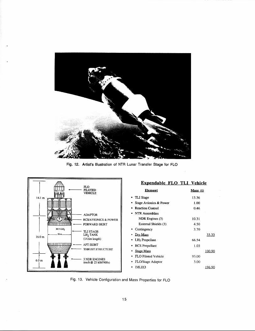
A representative NTR-powered lunar transfer stage using three 25 klbf-class composite fuel NDRs is illustrated in Figure 12, with stage dimensions and mass properties given in Figure 13. The main LH2 propellant tank has a 10 m diameter, -14.6 m length and d2/2 ellipsoidal domes. The tank is constructed of 2219-T87 AI, has a LH2 propellant capacity of -66.5 t (with an assumed 2.5% ullage), and is
designed to handle “4 g” launch loads under fully- fueled and loaded conditions. Avionics, power and RCS are located in the stage forward adaptor section. During launch, loads from the lander and TLI stage are transferred to the HLLV through a cylindrical ring or “skirt” located at the aft end of the tank. Fairings for the lander and tank MLI protection carry only aerodynamic loads and are expended before TLI. During the 28 minute TLI burn, in-space thrust loads from the three 25 klbf NDRs are transferred to the vehicle through the rear conical adaptor or “thrust structure.” An external disk shield for crew radiation protection is also assumed on each engine at present. Because of the substan!ial quantities of cryogenic and storable propellant between the crew and engines, it may be possible to reduce or even eliminate the need for external shielding. Analysis is ongoing with the Department of Energy national laboratories to determine actual shielding requirements for the FLO stage.
14
I I
14.1 m
16.0 m
i t
Fig. 12. Artist‘s Illustration of NTR Lunar Transfer Stage for FLO
FLO PILOTED VEHICLE
ADAPTOR
RCSIAVIONICS & POWER FORWARD SKIRT
TLI STAGE
(14.6111 length)
AFT SKIRT THRUST STRUCTURE
LH2 TANK
3 NDR ENGINES (each @ 25 klbf/900s)
ExDendable FLO TLI Vehicle
Element mfidll
TLJStage 13.36 Stage Avionics & Power 1 .oo Reaction Control 0.46 NTR Assemblies NDR Engines (3) 10.31 External Shields (3) 4.50
Contingency 3.70
~~ XI32 LH2 Propellant 66.54
RCS Propellant 1.03 StaeeMm m E O Piloted Vehicle 93.00 FLO/Stage Adaptor 3.00 IMLEO 196.90
Fig. 13. Vehicle Configuration and Mass Properties for FLO
15

MARS MISSION SCENAR 10s Over the past several years, NASA has been
examining the advantages and disadvantages of various trajectory classes, mission opportunities, and propulsion system options for its piloted missions to Mars.la.lQ From these and other studies,l the NTR has emerged as the leading candidate technology for primary space propulsion. This lead role was attributed both to its maturity (a large experimental database exists from both the Rover/NERVA and CIS nuclear rocket programs), and to its high Isp capability which enables the NTR to leverage a given propellant loading to reduce the total “in-space” transit time.
In FY89 and 90, NASA’s reference Mars mission was an “all-up,’’ 434 day, 2016 opposition-class mission with a 30-day surface stay and an inbound Venus swingby. “All-up” refers to an operational mode in which all of the payload and propellant required for the complete Mars mission is carried on a single vehicle (see Figure 1). Prior to FY89, NASA spent several years examining the benefits of splitting the “all-up” Mars mission into two parts -- a cargo mission and a piloted mission. In this so-called “split cargo/piloted sprint” mission mode, cargo would first be transported to Mars by a cargo vehicle(s) taking a slow, minimum propellant, low energy trajectory to Mars. The piloted vehicle would travel to Mars on a faster, higher energy trajectory after receiving confirmation that the cargo vehicle(s) had arrived safely in Mars orbit. By employing a “fast transit time” strategy, it is felt that crew health hazards resulting from long term exposure to weightlessness and space radiation can be minimized.
Three basic split/sprint mission modes are available for consideration.20 In the “all-up” mode, the piloted transfer vehicle (PTV) carries its own Mars excursion vehicle (MEV) and all of the trans- Earth injection (TEI) propellant required for the fast- transit return to Earth. The corresponding cargo transfer vehicle (CTV) carries only an autonomous lander outfitted with the necessary supplies to support the surface mission. In the “No MEV mode, the PTV carries only its return propellant and lands on Mars with a MEV carried on the CTV. A rendezvous in Mars orbit is therefore required between the PTV and the CTV. The third option, the “No MEV/No TEI Propellant” mode (also referred to as the “Minimum Piloted Mass” option) uses CTVs to pre-deploy all cargo including Earth-return propellant
at Mars. The TEI propellant can be transported either in a ”tanker” CTV or in a separate “return stage.” Both techniques still require a Mars orbit rendezvous between the PTV and CTV, but the latter option would eliminate the need for propellant transfer. An example of the size and mass variation of the cargo and piloted vehicles supporting a 2010 piloted Mars mission is shown in Figure 14 as a function of different split/sprint modes. Details on the particular vehicle designs and the associated mission scenario are reported on elsewhere.s.21
The Mars Exploration Study Team is presently assessing the requirements for supporting a piloted mission to Mars around 2010 using the “Minimum Piloted Mass” splitkprint mission approach as its reference. The mission profile also assumes the use of aerobraking and “in-situ” resource utilization to reduce the mass transportation requirements from Earth. Key features of the reference mission are illustrated in Figure 15. The piloted mission is preceded by three separate cargo missions which depart Earth orbit in September 2007 and arrive at Mars - 344 days later. Each cargo mission is launched on a single 200-240 t HLLV. The cargo missions use NTR propulsion for TMI and a “common” Mars aerobrake/aerodescent shell for either capture into Mars orbit or direct descent to the Mars surface. (The expendable NTR TMI stages are not shown in Figure 15.) As envisioned by EXPO, the initial cargo mission would transport both surface and Mars orbit payload elements. The surface payload consists of a “dry” Mars ascent stagelcrew cab combination along with the power system, LH2 propellant “feedstock,” and propellant production plant necessary to convert Martian COP into LOX/CH4 propellant for the piloted MEV ascent stage. This aspect of the reference Mars mission was first proposed by Zubrin3 in his “Mars Direct” scenario. The payload delivered to Mars orbit consists of a “fueled” trans-Earth injection stage and a “minimum mass” Earth return habitat. The later cargo missions deliver surface payload consisting of a habitat module, scientific laboratory, pressurized rover, consumables and miscellaneous supplies and spares needed to support a long-duration Mars exploration phase. After the operational functions of the habitat and surface facilities are verified and the ascent stage is fully fueled, the piloted vehicle leaves Earth in November 2009. It arrives at Mars - 180 days later using a “fast conjunction-class” trajectory,lep1Q which maximizes the exploration time at Mars while reducing the total in-space transit time to under a year. After a 540-day stay at Mars, the
16
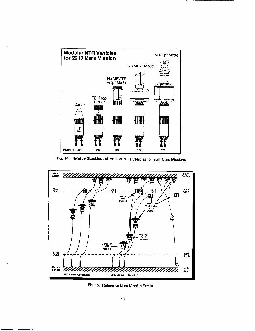
"All-Up" Mode Modular NTR Vehicles for 2010 Mars Mission
"No MEV" Mode
Cargo
IMLEO (I) - 201 243 334 579 750
Fig. 14. Relative SizeIMass of Modular NTR Vehicles for Split Mars Missions
MUS Surrw
Man Orb11
EuL Orblt
EsrL's surlam
zool Launch Opportuntty 2Ur) Lsuidi Oyyorluillly
Mars Surriice
Mars Orhil
Earlli Orbil
EnrIii's Yurfiire
Fig. 15. Reference Mars Mission Profile
17

Table 5. Mars Missionflransportation System Ground Rules and Assumptions ~ ~~
P i l O t d Mission
Payload 3 x (60-98.9 t) - MEV (~/41.5-64.4 t P/L) TEI Stage - cargo
Obtbound
- Payload Return - -
- Parking Orbits 407km
Perigee Burns 2 *crewsize -
ProDulsion NTRSystem
Propellant Isp
External Shield Mass
35.0 t 5.5 t
35.0 t 5.5 t 0.5 t
4Mkm 25Olanxl sol
2 6
- - -
(52.1-87.2 t) - - -
mkm
2 -3 6
crew Habitat ECRV MEV (wB5-50 t Habitat) crew Habitat ECRV Mars Return Samples Eaah Deparwe (circular) MarsAllival/DepaltlKe M D e p -
Cryogenic Hydrogen 900 sec (NDR) 960 sec (CIS) = 60 kg/ klbf thrust
Flight Performance Reserve Cool down (effective) Residual
RCSSystem
1% of usable propellant 3% of usable propellant 1.5% of total tank capacity
Propellant N204/MMH JSP 320 sec
Structure Tankage
Material Diameter Geometry
Insulation TMI application Only
Cargo & Piloted Vehicles w/NTR for TMI, MOC and disposal
Earth R e m Vehicle w/NTR for TMI, MOC, TEI and Disposal
Contingency Engine & External Shield All other dry masses
2219-T87 A1 10 m Cylindrical tank with &I2 domes
2" MLI + micro shield
3" MLI + VCS ("core" tank) 2" MLI + micro shield ("in-line" tank)
4" MLI + VCS/or 2" MLI + micro shield + refrigeration
15% 10%
Miscellaneous Gravity losses modelled for Earth and Mars orbit capture only
18

crew returns in the ascent portion of the MEV to a waiting Earth-return stage and habitat module to begin its preparation for a 6-month journey back to Earth. The total duration for the piloted mission is 900 days. The crew returns to Earth in the Mars ascent vehicle crew cab which is retained and used as the Earth crew return vehicle. After separation, the TEI stage and habitat continue along their interplanetary path for disposal into heliocentric space.
W Missionnra nsoortation S v s m es and A m
Mission and system ground rules and assumptions, and AV budgets for both an aerobrake and “all propulsive” version of the reference Mars mission are summarized in Tables 5 and 6. Table 7 provides additional AV requirements to account for disposal of spent cargo and piloted NTR stages, either along their interplanetary trajectories or into a stable heliocentric orbit between Earth and Mars at 1.19 astronomical units (A.U.). Table 5 includes details on payload masses (e.g., MEV, crew habitat, ECRV, etc.), parking orbits, primary and auxiliary propulsion, tankage, thermal protection and contingency factors used in this study.
While primary propulsion maneuvers are performed by the NTR engines, the NTR vehicle also executes midcourse and secondary maneuvers using a storable, bipropellant RCS system. For the Mars cargo and piloted missions, Mars orbital operation maneuvers on the order of 100 mls are provided for by the RCS system. Gravity losses are also taken into account in this study. For FLO, a “single burn” Earth departure scenario was used exclusively, while for Mars missions, a “two perigee burn“ approach was adopted. With the perigee propulsion techniques, propulsive energy can be imparted to the spacecraft more effectively. This reduces the gravity losses associated with a finite burn duration and a reduced vehicle thrust-to-weight ratio, which would accompany a spacecraft using a “cluster” of lower thrust NTR engines.
The NTR vehicle concepts developed in this study have varying levels of thermal protection consistent with their mission application. For a “limited life” stage used for TMI only, a 2 MLI system similar to that used on FLO is sufficient. In an “all propulsive” mission scenario, LH2 storage times range from - 8 months for the outbound piloted vehicle to - 1 year for the Mars cargo vehicle. Subsequent removal of these vehicles from Mars
Table 6. Mars Cargo and Piloted Mission AV Budgets (Ideal)
Vehicle Outbound Inbound Total TMI MOC TEI Total Mission LGth Transit Time Transit Time Mission Time AV AV AV Ideal AV Mode (drys) (days) (days) (kds) ( k d s ) ( k d s ) ( k d s )
344 NA
344 N A
180 180
180 180
200 180
2.20 180
344 180
344
344
900 Mars)
880 (520 8 Mars)
884 ( 5 W 3 Mars)
884 (484 @ Mars)
1677 (11S3@ Mars)
3.777 0.837 N A 4.631
3.777 AIB NA 3.116
4.064 A/B N A 4.064
4.447 2.571 N A 7.018
4.243 1.952 N A 6.195
4.227 1.396 NA 5.622
3.777 0.837 1.787 6.401
IW. V besed on 407 km ClrQllM obit at Earth and 250 X 33793 Mars parking orMt. I-boseo ClpProXknate 0 ’dOuMe pldavnodal alignment pncllty of 160 mEs mUSt be added to Le TEI AV value shown.
burn’ EarM dopaflure RLUSt be mMed to the TMI AV shown.
19

Table 7. Mars Disposal AV Requirements
1 Missbn Disposal InlUated Req‘d Maneuvers AV Disposal
(kmls) Earth Encounter
Probabllily
2007 Cargo after TMll none - TMI slage 0 12% in 106 (A/B@Msn) bekreMOC disposed along years
Interplanetary path
I after cargo clrcularlze @ 1.19AU from M s n orblt depart Mars orbW 0.664 0
dellvery 1.662
- 2007 Cargo from Mara orblt depart Mars orblt to 0.360 0.2% In 10A6 ( A P Q M s n ) after cargo 1.19AU I dispose ~ 0 years
dellvery along Interplanetary 0.380
2009 Plloted alter TMll none - TMI slqe 0 3.8% In 106 path
(Ai8 QP Mats) betore MOC disposed along years Interplanetary path
2009 Plloted from Mars orbit depart Mars orbit/ 0.664 0 (AP @ Mars) after cargo clrcularlze 8 1.19AU 0.998
dellvery 1.662
2009 Plloted from Mars orblt depart Mars orbit lo 0.316 0.2% In 106
dellvery along Interplanetary 0.3 16 (UP @ Man) after cargo 1.19AU I dlspose - 0 years
path
* 2007 Earth after Earlh flyby Earth gravlly assist/ 0 0 Return Stage (LECFiV clrcularlze Q 1.19AU 3.080 (AP Q Mars) separallon 3.060
2007 Earth after Earth flyby Earth gravlty asslsV 0 1.8% In 106 Return Slsg. 6 ECRV dlsposal dong years (NP QP Mars) separatlon Interplanetary path
orbit to a stable disposal orbit at 1.19 A.U. can double the total mission duration for the cargo vehicle and quadruple it for the outbound piloted vehicle “core” stage. The AV penalty for disposal to this location is also appreciable at ,. 1.66 km/s. A second disposal option for an “all propulsive” NTR scenario would be to leave the transfer vehicles on their flight paths to 1.19 A.U., but to eliminate the final capture/circularization burn. This option reduces the disposal AV requirements to less than 0.4 km/s. It does, however, allow for possible future planetary encounters/collisions. Calculations by Stancatin2 using the Planetary Encounter Probability Analysis (PEPA) code indicate that the probability for a NTR vehicle collision with Earth is low (s 1.8% in 106 years) for the “all propulsive” cargo and piloted missions. In the reference mission scenario, which uses aerobraking at Mars, the probabilities for collision in 106 years are 3.8% and 12% for the piloted and cargo missions, respectively. The increased probability for the cargo missions are due to their near-Hohmann trajectories (see Table 7).
To accommodate these two disposal options, the “all propulsive” Mars cargo vehicles utilize a 3” MLI system with a vapor-cooled shield (VCS) located midway through the MLI to reduce heat leaks. The “outbound” piloted vehicle is a “two tank configuration consisting of a common “core” stage and an “in-line” LH2 tank which is drained during the TMI maneuver. The “core” stage uses the 3“ MLVVCS system while a 2” MLI system is used on the “in-line” tank.
The “all propulsive” NTR-powered Earth return vehicle has the most demanding requirements for thermal protection with a mission ellapsed time between TMI and TEI of 1497 days (- 4.1 years). Two different thermal protection system (TPS) options were examined--a passive System Using a 4” MLINCS combination and an active system using a 2” MLI blanket and a turbo-Brayton refrigerator. For the active TPS, a survey was made of various cryogenic refrigeration systerns.2324 For large LHz tanks requiring a refrigeration capacity in the 10 to
20

100 watt cooling range, a turbo-Brayton refrigerator system was selected with the specific mass and power requirements shown earlier in Table 3. These system characteristics were used to estimate the inert weight and electrical power demands for a "refrigerated" Earth return vehicle "core" stage employing "dual mode" NTR engines for both propulsion and power. Parametric analysis indicated a minimum mass for the combined MLI and refrigeration system occuring at - 1.5" to 2" of MLI.
' ~ ' ~ ~ ~ ~ ~ / ( ~ ~ NTR Co-
2 x 50 klbf
In the reference Mars scenario depicted by EXPO in Figure 15, the initial cargo mission, utilizing an NTR-powered TMI stage, transports major surface and orbital payload elements to Mars using a single 240 t class Saturn V-derived HLLV. The length available for the Mars cargo and piloted spacecraft is - 44.8 m. It is set by the length of the Saturn V- derived HLLV's first and second stages (- 80.2 m), and the height of the Vertical Assembly Building (VAB) doors (- 125 m). Subsequent analyses by NPO has indicated that this initial mission is impractical since payload elements exceed both the lift capability of the Saturn V-derived HLLV and the available length limits specified above.
"2 Perigee Burn" Earth Departure
NDR (Isp = 900 s)
212.1 126.3 I 17.9
CIS (ISP = 960 S)
200.9 I 25.1 I 16.2
As a result of these findings, the NPO has split the first cargo mission into two separate missions. Because the 2007 cargo missions utilize a minimum energy, Hohmann-type trajectory with a C3 =13.41 km21s2, it is the 2009 piloted mission with its short outbound transit time (180 days) and higher energy requirements (C3 = 20.07 km21s2) that determines the size of the TMI stage. Parametric data for the 2009 piloted mission is presented in Table 8 which shows variations in IMLEO, engine burn time and LH2 tank length for NDR- and CIS-powered TMI stages with different engine clustering arrangements. The higher specific impulse and engine thrust-to-weight ratio advantage of the CIS concept over the NDR translates into a 5% reduction in IMLEO and a 10% reduction in tank size for this limited "TMI only" mission application. A cluster of two 25 klbf NDRICIS engines has the lowest IMLEO and tank size. Burn durations of the magnitude shown in Table 8 have also been previously demonstrated in ground tests both in this country and in the CIS.
3 x 25 klbf 212.9 135.6 118.1
For the reference Mars mission, NPO has selected a TMI stage powered by three to four 15 klbf NDR (or CIS) engines. In addition to having characteristics comparable to the two 25 klbf NDR stage, this clustered arrangement can increase the
200.5 I 33.8 I 16.4
2 x 25 klbf 205.0 I 52.3 I 17.7 193.2 I 49.9 I 16.7
3 x 15 Wbf 4 x 15 klbf
2 x 15 klbf I 208.7 I 94.2 I 18.9 195.9 I 89.0 I 17.0 ! 207.6 I 59.5 I 18.1
212.1 144.7 I 18.2
198.8 I 57.7 I 16.7
200.9 I 42.8 I 16.5
21

potential for successful mission completion even with the loss of one or two engines, an option that does not exist with the two 25 klbf NDR configuration. A 15 klbf NTR-powered injection stage, launched on a single Titan IV launch vehicle, can also enable a variety of "robotic" science orbiter missions to Saturn, Uranus, Neptune, and Pluto24 Finally, the ground facilities for testing a 15 klbf NTR with a closed effluent treatment system are also expected to be developed more quickly and at lower cost due to the reduced engine size and effluent throughput.25
The relative size and mass of the Mars cargo and piloted vehicles with various aerobraked payloads and a "common" NDR-powered TMI stage are shown in Figure 16. In the piloted mission, the outbound crew habitat is integrated into an 87.5 t MEV which is sized to land 50 t of surface payload along with a crew of six and an emergency crew return vehicle (ECRV)/capsule. The 5.5 t ECRV sits atop a central LOX/CH4-fueled descent propulsion stage (with Isp E 376 s) which is used to provide - 500 m/s of final terminal descent AV to the MEV following aerobrake separation. During liftoff, the ECRV can be removed from the Saturn V-derived HLLV via a launch escape system similar to that
used on Apollo. The central stage can also separate from the peripheral MEVIhabitat structure during a TMI abort and provide up to - 2 km/s of emergency Earth return AV. The low lift-to-drag (UD) ratio (c 0.3) biconic MEV design has a 10 m diameter at its base and is - 12 m in overall height.
Scaling data used to approximate MEV mass as a function of Mars surface payload for both aerobraking and NTR propulsive capture at Mars is shown in Figure 17. The mass of the "dual use" aerobrake/descent shell has been set at 15% of the spacecraft mass entering the Mars atmosphere including the aerobrake system. The NTR TMI stage and MEV payload adaptor have been previously jettisoned and are not included in this entry mass. With the NTR providing propulsive capture at Mars, a lighter weight aerodescent shell set at 10% of the Mars entry mass is utilized on the MEVs. The greater mass of the aerobrake system over that of the aerodescent shell is attributed to its thicker heat shield requirements and the need for additional propellant and propulsion hardware to capture into a final Mars parking orbit following the aerobraking maneuver.
2007 C - L O X / C H 4 TEIS & Hab
2QQ9 Piloted Mission L Piloted MEV & Surface Hab
. . . . 2007 Carno M@ Hab Module & Lander "Dry" Ascent Stage & Lander
IS.Om
I --I-
20.6 m'
I 4jm
I I
16.3 m T 19.0 m t
12.0 m
1
IMLEO = 216.61 216.6t 204.7t 212.lt ExpendaMe TMI Stpoe LH2 Tank (0 18.2 rn length) slzed by 2009 Mara Piloted Mlssion
Fig. 16. Reference Mars Cargo and Piloted Vehicles - "Aerobraked" NDR Configurations
22

100
80
e 60
z
P 3 4 0 I-”
20
0
Mlander = 10% Landed Mass
............................
0 10 20 30 40 5 0 60 70 Mars Surface Payload (1)
Fig. 17. Mars Excursion Vehicle (MEV) Mass Scaling
The “dual use” aerobrake and aerodescent shell subsystems are assumed to be jettisoned from the MEV before the final terminal descent and landing maneuver is initiated by the MEV’s descent stage. The MEV lander mass, which includes structure for the lander, tankage for the LOWCH4 descent propellant, landing gear and propulsion, has been set at 10% of the total mass landed on Mars (descent stage and surface payload). A 1% flight performance reserve (FPR) and 0.3% per month boiloff rate during Earth-to-Mars (ETM) transit have been assumed for the MEV’s LOX/CH4 propellant.
The TMI stage LH2 tank has a 10 rn diameter and 18.2 m length. Its LH2 propellant capacity is - 86 t assuming a 2.5% ullage. The total TMI stage “dry” mass includes the LH2 tank, thermal and micrometeoroid protection, forward and aft skirts, thrust structure, propellant feed system, avionics, and power. Earth-to-Mars MCC maneuvers are provided by a storable bipropellant RCS system onboard the “spent“ NTR TMI stage. Following separation of the aerobraked payload and a Mars flyby, the TMI stage is disposed of along its interplanetary path. The probability for subsequent Earth encounters is estimated at 3.8% during a 106
year time period (see Table 7). The piloted Mars spacecraft departs LEO using four 15 klbf NDR engines each of which perform two 22.5 minute perigee burns which constitute the TMI maneuver. The IMLEO for the piloted Mars vehicle is - 212.2 t and the overall spacecraft length is - 37.3 m (well within the 44.8 m VAB limit). A summary of the element masses for the reference 2009 piloted and 2007 cargo missions is provided in Table 9.
The three cargo missions departing LEO in September 2007 utilize a “3 NDR” version of the TMI stage used on the 2009 piloted mission. Taking full advantage of the 86 t propellant capacity of the TMI stage allows cargo missions 1 and 2 to transport up to 64.4 t of surface payload. They can also accommodate up to 120 days of LH2 boiloff in LEO, assuming 60 days between HLLV launches and a “convoy-type” departure of the three cargo vehicles. The payload on the first cargo mission consists of a “common” Mars landerldescent stage, a Mars ascent vehicle (MAV) and crew cab, which doubles as an ECRV, and UP to 50.3 t of surface payload. About 6 t of this surface payload is associated with a deployable “teleoperated nuclear power reactor (at -5.5 t) and a propellant production plant
23
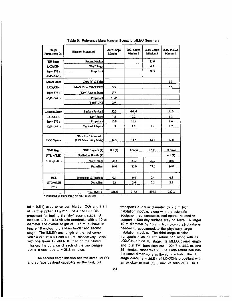
Table 9. Reference Mars Mission Scenario IMLEO Summary
I TotalIMLEOl 216.6 I 216.6 I 204.7 I 212.2 I * produced @ Mars using “in-situ” resources
(at - 0.5 t) used to convert Martian COP and 2.9 t of Earth-supplied LH2 into - 51.4 t of LOXICH4 propellant for fueling the “dry” ascent stage. A medium LID (- 0.6) biconic aerobrake with a 10 m diameter and overall height of - 15 m is shown in Figure 16 enclosing the Mars lander and ascent stage. The IMLEO and length of the first cargo vehicle is - 216.6 t and 40.3 m, respectively. Also, with one fewer 15 klbf NDR than on the piloted mission, the duration of each of the two perigee burns is extended to - 28.8 minutes.
The second cargo mission has the same IMLEO and surface payload capability as the first, but
transports a 7.6 m diameter by 7.6 m high habitation module, along with the scientific equipment, consumables, and spares needed to support a 500-day surface stay on Mars. A larger 10 m diameter by 16.3 m high biconic aerobrake is needed to accommodate the physically larger habitation module. The third cargo mission transports a 35 t Earth return hab along with its LOX/CH4-fueled TEI stage. Its IMLEO, overall length and total TMI burn time are - 204.7 t, 44.3 m, and 55 minutes, respectively. The Earth return hab has the same dimensions as the surface hab. The TEI stage contains - 38.5 t of LOX/CH4 propellant with an oxidizer-to-fuel (O/F) mixture ratio of 3.6 to 1
24

--the same as that used in the Mars descent and ascent stages (see Table 9). contained within three common size tanks - 2.53 m in diameter by - 3.08 m in height. The overall length of the Earth return stage including its LOXICH4 engines is - 14 m. A mass fraction of 10% was assumed for sizing purposes resulting in a TEI stage mass of - 4.3 1.
The propellant is
At LEO departure, the total mass of the Earth return stage (minus the payload adaptor and aerobrake) is - 77.8 1. Propellant boiloff reduces this to - 76.5 t prior to the Mars aerobraking maneuver and - 72 t at the initation of the TEI burn. With a 15% mass fraction assumption, the aerobrake mass is estimated to be - 13.5 t, while the overall height of the biconic aerobrake needed to accommodate the large Earth return stage is - 19 m. Figure 16 shows the relative aerobrake size for cargo missions 1 through 3 while Table 9 utilizes the same aerobrake mass in estimating the IMLEO requirements for cargo missions 1 through 3. To minimize development costs, a “common aerobrake” would be utilized on all the cargo missions and sized to accommodate both the largest and the heaviest payload elements envisioned in the mission sequence. For cargo mission 3, a heavier aerobrake than that assumed in Table 9 would increase the IMLEO and more fully utilize the propellant capacity of the TMI stage. A heavier, oversized aerobrake on cargo missions 1 and 2 would lead to a decrease in delivered surface payload, since these TMI stages are already operating at maximum stage capacity.
In total, - 165 t of surface payload are delivered by cargo missions 1 and 2, and the 2009 piloted mission using NDR engines. With CIS technology and the same payloads shown in Table 9, the IMLEO values for cargo missions 1 and 2, cargo mission 3, and the first piloted mission are 204.9 t, 194.5 t, and 200.9 1, respectively. The TMI stage, again sized by the 2009 piloted mission, has a 16.5 m long LH2 tank (see Table 8) with a 77 t propellant capacity. With this reduced size, the mass of the “dry” TMI stage is - 18.8 t versus 20.2 t for the NDR-powered stage. Finally, the “2 perigee burn” TMI maneuver requires total engine burn times for cargo missions 1 and 2, cargo mission 3, and the 2009 piloted mission of - 55.1, 52.7, and 42.8 minutes, respectively.
Mars Cargo Vehicle - “All Propulsive” 0-
In addition to the reference mission scenario, NPO has examined an “all propulsive” NTR mission architecture and arrived at vehicle designs for the cargo, Earth return, and piloted missions. Parametric data is presented in Table 10 showing variations in IMLEO, engine burn time, and LH2 tank length for NDR- and CIS-powered Mars cargo vehicles with different engine clustering arrangements. The two 25 klbf NDRlClS stage has the lowest IMLEO, followed by the two 50 klbf and the three 15 klbf engine configurations. The three 15 klbf NDR/CIS option has been selected for the “all propulsive” reference cargo vehicle with CIS technology being used here for discussion purposes. It is envisoned that an upgraded and “stretched” version of a proven FLO NTR TLI stage can form the basis for the cargo vehicle design. Requirements would include extending the length of the three 15 klbf CIS FLO stage from 14 m (see Table 4) to - 19.5 m, upgrading the TPS and avionics, and increasing fuel cell reactants and RCS propellants.
The “all propulsive” cargo mission scenario would begin with a “2 perigee burn” TMI manuever lasting - 53 minutes. On reaching Mars, the cargo vehicle performs a third 8 minute MOC burn to achieve a 250 x 33,793 km (- 24 hour) elliptical parking orbit. At the appropriate time, the MEV separates from the cargo vehicle “core stage,” performs a short de-orbit burn, and uses a combination of “low energy” aerobraking and terminal descent propulsion to land - 50 t of payload on the Mars surface. After - 30 days in Mars orbit, a short 1.1 minute burn places the “spent“ core stage on a trajectory to 1.19 A.U. with disposal along the interplanetary path. The disposal AV requirement is 0.38 km/s and the probability of Earth encounter is estimated at 0.2% in 106 years (see Table 7).
The overall configuration and mass properties for the “all propulsive” Mars cargo vehicle are shown in Figure 18. Two noticeable differences in the cargo vehicle over that of the FLO TLI stage are the absence of the biological external disk shields, and the extended cylindrical forward adaptor required to house the increased fuel cell reactants and RCS propellant tanks. The IMLEO is just under 200 t at
25
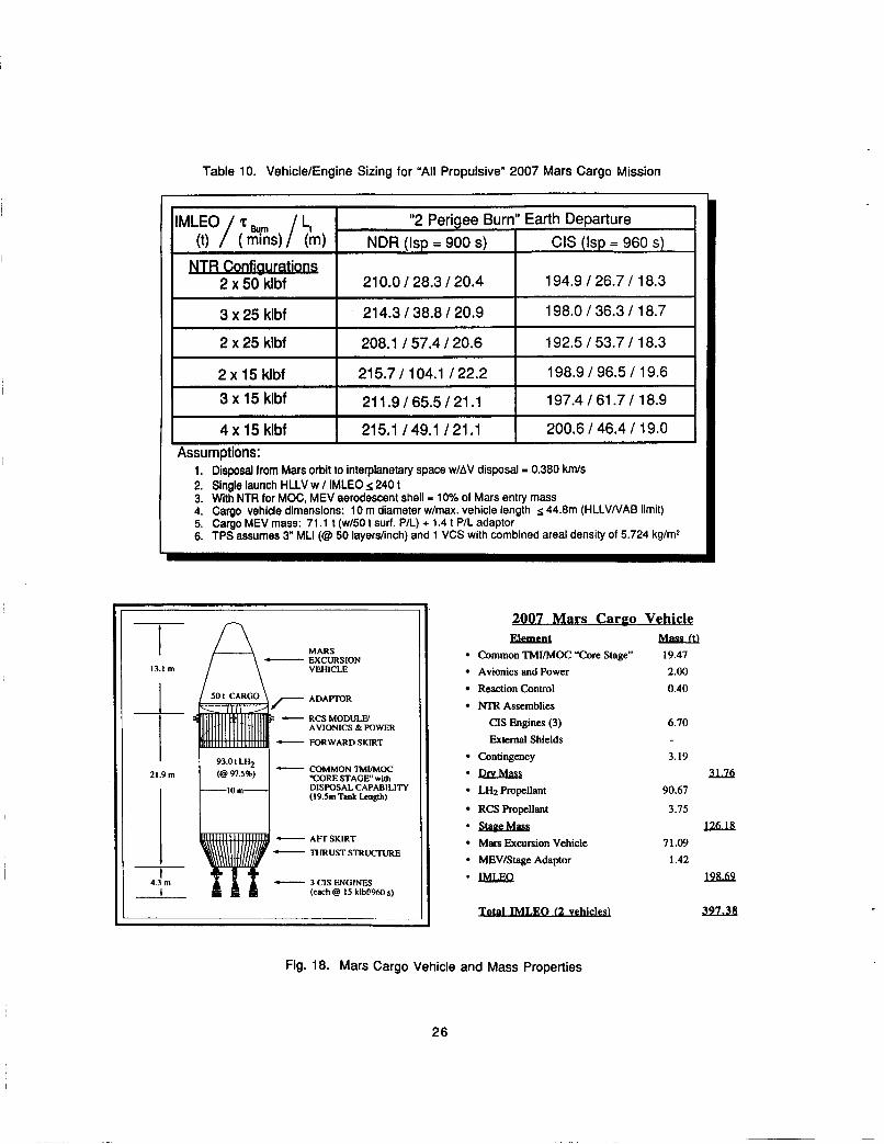
Table 10. Vehicle/Engine Sizing for "All Propulsive" 2007 Mars Cargo Mission
I Assumptions:
I 21 0.0 I 28.3 I 20.4 I 194.9 126.71 18.3 I '"LEO/ 7 barn / 4
(t) ( mlns) (m) "2 Perigee Burn" Earth Departure
NDR (ISP = 900 S) I CIS (ISP = 960 S)
I ~ 3 x 15 klbf I 211.9165.5121.1 I 197.4161.71 18.9 I
3 x 25 klbf
2 x 25 klbf
2 x 15 klbf
I 4 x 15 klbf I 215.1 / 49.1 121.1 I 200.6 146.4 119.0 I
214.3 138.8 120.9
208.1 I 57.4 I 20.6
215.7 I 104.1 122.2
198.0 I 36.3 I 18.7
192.5 I 53.7 I 18.3
198.9 I 96.5 I 19.6
21.9111 F<
1. Disposal from Mars orbit to interplanetary space w/AV disposal = 0.380 km/s 2. Single launch HLLV w I IMLEO s, 240 t 3. With NTR for MOC, MEV aerodescent shell - 10% of Mars entry mass 4. Cargo vehicle dimensions: 10 m diameter w/max. vehicle length 5. Cargo MEV mass: 71.1 t (w/50 t surf. PIL) + 1.4 t P/L adaptor 6. TPS assumes 3" MLI (@ 50 layerslinch) and 1 VCS with combined areal density of 5.724 kg/m*
44.8m (HLLVIVAB limit)
FOMMONTMUMOC CORE STAGE" with DISPOSAL CAPABILITY (19.5111 Tank Length)
ADAPlYlR - R C S M O D U W AVIONICS & POWER
FORWARDSKIRT I A W S K I R T THRUSTSTRUCTURE
- 3CISWGINES t
(each @ 1.5 klbf/960 s)
1 4.3 m
I
2007 Mars Cargo Vehicle Element Mfmm
Common TMI/MOC "Core Stage" 19.47 Avionics and Power 2.00 ReactionControl 0.40 NTR Assemblies
CIS Engines (3) 6.70 External Shields
Contingency 3.19
*QlxMW LHz Propellant RCS Propellant
Mars Excursion Vehicle MEVIStage Adaptor
-lMLEQ
*sbuLMlu
0 (2 v e W
11l6 90.67
3.75 1261[(
71.09 1.42
m.69
WL28
Fig. 18. Mars Cargo Vehicle and Mass Properties
26
198.7 t and the overall spacecraft length is - 39.3 m, which allows for longer MEV designs if selected. The cargo vehicle LH2 tank has a 10 m diameter and 19.5 m length, which accommodates 93 t of LH2 propellant assuming a 2.5% ullage. The 19.5 m LH2 tank illustrated in Figure 18 is - 0.6 m longer than that shown in Table 10 for the three 15 klbf CIS configuration. The cargo vehicle tank size in this study is driven by the Earth return stage mission requirements and the desire for commonality of engine and stage components. With this slightly oversized LH2 tank, the first cargo vehicle delivered to orbit can accommodate up to 180 days of LH2 boiloff (- 3.6 t) while awaiting the arrival of the second cargo vehicle and the Earth return stage for a "convoy-type'' departure from LEO.
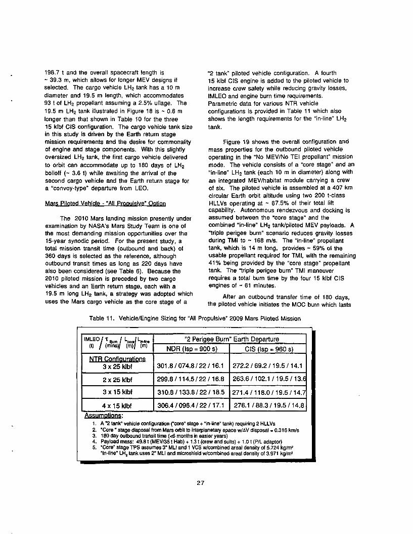
NTR Confiaurations 3 x 25 Wbf
2 x 25 klbf
3 x 15 klbf
4 x 15 klbf
Mars Piloted Vehicle - "All ProDulsive" ODtion
301.8 I 074.8 I 22 I 16.1
299.8 I 114.5 122 I 16.8
310.8 I 133.8 I22 I 18.5
306.4 1096.4 I 22 I 17.1
272.2 I 69.2 I 19.5 I 14.1
263.6 I 102.1 I 19.5 I 13.6
271.4 I 118.0 I 19.5 I 14.7
276.1 I 88.3 I 19.5 I 14.8
The 2010 Mars landing mission presently under examination by NASA's Mars Study Team is one of the most demanding mission opportunities over the 15-year synodic period. For the present study, a total mission transit time (outbound and back) of 360 days is selected as the reference, although outbound transit times as long as 220 days have also been considered (see Table 6). Because the 2010 piloted mission is preceded by two cargo vehicles and an Earth return stage, each with a 19.5 m long LH2 tank, a strategy was adopted which uses the Mars cargo vehicle as the core stage of a
"2 tank piloted vehicle configuration. A fourth 15 klbf CIS engine is added to the piloted vehicle to increase crew safety while reducing gravity losses, IMLEO and engine burn time requirements. Parametric data for various NTR vehicle configurations is provided in Table 11 which also shows the length requirements for the "in-line" LH2 tank.
Figure 19 shows the overall configuration and mass properties for the outbound piloted vehicle operating in the "No MEV/No TEI propellant" mission mode. The vehicle consists of a "core stage" and an "in-line" LH2 tank (each 10 m in diameter) along with an integrated MEV/habitat module carrying a crew of six. The piloted vehicle is assembled at a 407 km circular Earth orbit altitude using two 200 t-class HLLVs operating at - 67.5% of their total lift capability. Autonomous rendezvous and docking is assumed between the "core stage" and the combined "in-line" LH2 tanklpiloted MEV payloads. A "triple perigee burn" scenario reduces gravity losses during TMI to - 168 m/s. The "in-line" propellant tank, which is 14 m long, provides - 59% of the usable propellant required for TMI, with the remaining 41% being provided by the "core stage" propellant tank. The "triple perigee burn" TMI maneuver requires a total burn time by the four 15 klbf CIS engines of .. 61 minutes.
After an outbound transfer time of 180 days, the piloted vehicle initiates the MOC burn which lasts
Table 11. Vehicle/Engine Sizing for "All Propulsive" 2009 Mars Piloted Mission
I . I
27

- rn 13.1 m- MARS VEHICWCREW EXCURSION
HABITAT
I -ADAPTOR
c- FORWARDSKIRT t 63.31 w12
16:4m I I C “IN-LINE”TM1TANK ( I h Tank Lenglh)
I C- AFTSKIRT
, 7 DOCKINGPLANE
I c- FORWARDSKIRT
MARS CARGO VEHICLE I Etfj -TMMYMOC“€ORE” PROPELLANT TANK w/ 21.9111 DlSFOSALCAPABlLlTY
C- AFTSKIRT
C- THRUSTSTRUCTURE
4 CIS ENGINES (each 8 I5 klbll96Os)
I 4.3 m
1 I
C- AFTSKIRT
C- THRUSTSTRUCTURE
4 CIS ENGINES (each 8 I5 klbll96Os)
I 4.3 m
1 I
for - 22.7 minutes. After two days in Mars orbit, the crew separates the integrated MEVIsurface habitat from the piloted vehicle and descends to the Martian surface to begin a 516-day stay. Over the next four weeks, the piloted vehicle “core stage” autonomously undocks and separates from the spent “in-line” LH2 tank and prepares for its final disposal burn requiring a AV of - 0.32 km/s. A short - 1 minute burn disposes of the “spent” core stage into interplanetary space where its probability of encountering Earth is the same as that of the Mars cargo vehicle (see Table 7).
Of the three different types of spacecraft comprising the “all propulsive” NTR Mars architecture, it is the Earth return vehicle which has the most challenging and demanding set of mission requirements. In the current scenario being proposed by EXPO, the spacecraft must function autonomously for - 4.1 years in interplanetary and Mars orbital space before being boarded by the crew for their 6-month journey back to Earth. For all but the last 6 months of the mission, the Earth return vehicle’s “core” stage contains significant
2010 Mars Piloted Vehicle “No MEV/No TEI Propellant Mission”
ELement B l a S L u
Piloted MEVlSurface Hab (@ 3%) 52.06 Common TMI / MOC “Core Stage” 20.23 TMI “In-Line” Tank 16.76
2.00 Reaction Control System 0.44 Stage Avionics & Power
NTR Assemblies CIS Engines (4) 8.93 External Shields (4) 3.84
Contingency 6.32
LH2 Propellant 153.95 le Drv Mass lx!..s
RCS Propellant 4.43 *LEILEa m33.4
Fig. 19. Mars “Outbound” Piloted Vehicle and Mass Properties
quantities of LH2 propellant requiring a “robust” thermal protection system to minimize boiloff. Parametric data for the 2007 Earth return vehicle is presented in Table 12 for two different NTR engine types (NDR and CIS) and operating modes (“propulsion only” and “dual mode” propulsion and power operation), and two different TPS options--a passive 4” MLINCS system combination and an active system using a 2” MLI blanket and a turbo- Brayton refrigeration system.
As is evident, significant quantities of LH2 are lost to boiloff with the “propulsion only/passive TPS system” option. The three 25 klbf and four 15 klbf NDR and CIS vehicle configurations have comparable IMLEO (approaching the 240 t HLLV limit) and LH2 tank lengths. The mission burn times for the four 15 klbf NDR and CIS configurations are - 25% longer, however, due to the lower total thrust level. By introducing “dual mode” NTR and refrigeration systems into the basic vehicle configurations, dramatic reductions in IMLEO, mission burn time, and LH2 tank size become possible. For the four 15 klbf CIS configuration, these reductions are - l6%, 14’10, and 22%, respectively. For the “all propulsive” NTR Mars architecture discussed here, the NPO has
28
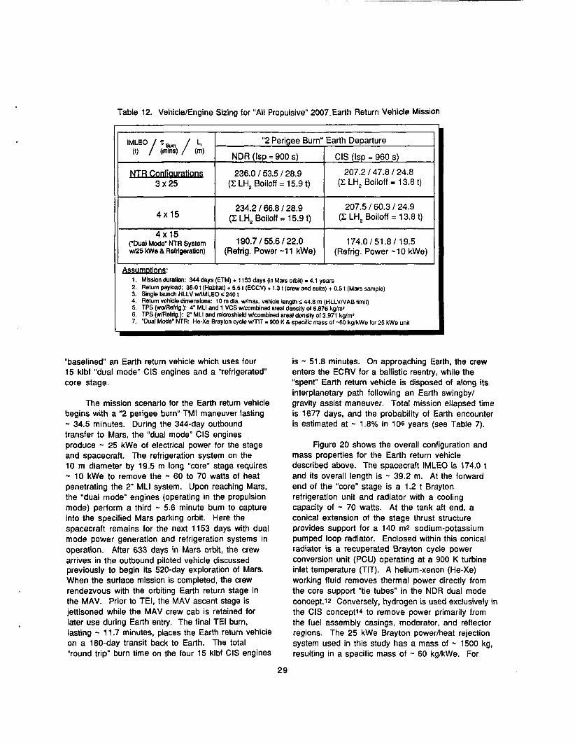
Table 12. VehiclelEngine Sizing for "All Propulsive" 2007.Earth Return Vehicle Mission
''LEO/ 7 Burn / (I) (mins)
NTR Confiaurations 3 x 25
"2 Perigee Burn" Earth Departure
NDR (ISP = 900 S) CIS (ISP = 960 S)
236.0 153.5 128.9 207.2 147.8 I 24.8 (Z LH, Boiloff = 15.9 t) (Z LH, Boiloff = 13.8 t)
234.2 166.8 128.9 (Z LH, Boiloff = 15.9 t) /I 4 x 1 5 I 207.5 160.3 124.9
(Z LH, Boiloff = 13.8 1)
I I I J
1, Mission duration: 344 days (ETM) + 11 53 days (in Mars orbit) - 4.1 years 2. Return payload: 35.0 t (Habitat) + 5.5 t (ECCV) + 1.3 t (crew and suits) + 0.5 t (Mars sample) 3. Single launch HLLV w/lMLEO S 240 t 4. Return vehicle dimensions: 10 rn dia. w/max. vehicle length I, 44.8 m (HLLVNAB limit) 5. TPS (wdReftig.): 4" MLI and 1 VCS w/cornbined areal density of 6.876 kgmz 6. TPS (w/Refrig.): 2" MLI and rnicroshiekl w/cornbined areal density of 3.971 kg/mz 7. "Dual Mode" NTR: He-Xe Brayton cycle wnlT - 900 K 8 specific mass of -60 kg/kWe for 25 kWe unit
("Dual Mode" NTR System we5 kWe & Refrigeration)
190.7 I 55.6 I 22.0 (Refrig. Power -1 1 kWe) 4x15 I
"baselined an Earth return vehicle which uses four 15 klbf "dual mode" CIS engines and a "refrigerated" core stage.
174.0151.81 19.5 (Refrig. Power -1 0 kWe)
The mission scenario for the Earth return vehicle begins with a "2 perigee burn" TMI maneuver lasting - 34.5 minutes. During the 344-day outbound transfer to Mars, the "dual mode" CIS engines produce - 25 kWe of electrical power for the stage and spacecraft. The refrigeration system on the 10 m diameter by 19.5 m long "core" stage requires - 10 kWe to remove the - 60 to 70 watts of heat penetrating the 2" MLI system. Upon reaching Mars, the "dual mode" engines (operating in the propulsion mode) perform a third - 5.6 minute burn to capture into the specified Mars parking orbit. Here the spacecraft remains for the next 1153 days with dual mode power generation and refrigeration systems in operation. After 633 days in Mars orbit, the crew arrives in the outbound piloted vehicle discussed previously to begin its 520-day exploration of Mars. When the surface mission is completed, the crew rendezvous with the orbiting Earth return stage in the MAV. Prior to TEI, the MAV ascent stage is jettisoned while the MAV crew cab is retained for later use during Earth entry. The final TEI burn, lasting - 11.7 minutes, places the Earth return vehicle on a 180-day transit back to Earth. The total "round trip" burn time on the four 15 klbf CIS engines
is - 51.8 minutes. On approaching Earth, the crew enters the ECRV for a ballistic reentry, while the "spent" Earth return vehicle is disposed of along its interplanetary path following an Earth swingby/ gravity assist maneuver. Total mission ellapsed time is 1677 days, and the probability of Earth encounter is estimated at - 1.8% in 106 years (see Table 7).
Figure 20 shows the overall configuration and mass properties for the Earth return vehicle described above. The spacecraft IMLEO is 174.0 t and its overall length is - 39.2 m. At the forward end of the "core" stage is a 1.2 t Brayton refrigeration unit and radiator with a cooling capacity of - 70 watts. At the tank aft end, a conical extension of the stage thrust structure provides support for a 140 m2 sodium-potassium pumped loop radiator. Enclosed within this conical radiator is a recuperated Brayton cycle power conversion unit (PCU) operating at a 900 K turbine inlet temperature (TIT). A helium-xenon (He-Xe) working fluid removes thermal power directly from the core support "tie tubes" in the NDR dual mode concept.12 Conversely, hydrogen is used exclusively in the CIS concept14 to remove power primarily from the fuel assembly casings, moderator, and reflector regions. The 25 kWe Brayton powedheat rejection system used in this study has a mass of - 1500 kg, resulting in a specific mass of - 60 kg/kWe. For
29

DOCKING PORT
351 EARTH RETURN HAB
HABLSTAGE ADAFTOR REFIUGERAnON UNIVRADIATOR RCS MODULW AVIONICS &POWER
FORWARD SKIRT
201’ F:oW%’J% C- ,‘El COMMON “COR@” TMUMOC STAGE
(19.h Tank Length)
I 6dm 1
1 I
4.3 rn
c- c-
f-
AFT SKIRT THRUSK SIRUCIURE /RADIATOR SUPPORT
‘25.50 kWe” PCU /CONICAL RADIATOR
4 “DUAL MODE” CIS ENGINES ( c r h Q IS klbf/9Mk)
2007 Earth Return Vehicle Element rdf4d.o
“Minimal” Crew Habitat System 35.00
Common TMI/MOc/TEI “Core Stage” 18.78 Stage Avionics & Power 2.00 Reaction Control 0.46
NTR Assemblies CIS “Dual Mode”Engines (4) 8.93 External Shields (4) 3.84
Brayton Power System (@ 25 kW,) 1.50
LH2 Refrigeration System (@ 70 W,) 1.20
Contingency 4.45
*QlxMw u LH2 Propellant 93.00
RCS Propellant 4.84
-IMLEQ ll4m
Fig. 20. Earth Return Vehicle and Mass Properties
comparison, an advanced potassium Rankine PCU operating at a TIT of 1144 K would have a specific mass of - 34 kg/kWe and a radiator area of - 14.2 m2 for the same power level.
For “dual mode” NTR systems, the issue of “burnup” of the enriched uranium-235 (U235) isotope must also be addressed. In thermal reactors, the consumption rate of U235 (due both to fission and radiative capture reactions) is approximately 1.24 grams/day per megawatt of power.26 Similarly, for NDR-type systems, the reactor core contains - 0.1 kg of enriched U235 per megawatt of power output. For a 15 klbf NDR engine, with an Isp of 900 s and a reactor power level of 320 MWt, the U235 inventory is - 32 kg. Assuming that during the power generation phase each of the four 15 klbf NTRs supply thermal power to the 17.5% efficient Brayton PCU and considering parasitic power losses, individual reactor power levels of - 50 kWt are indicated. If this level of power is maintained for the entire 1677 days, - 104 grams of U235 would be consumed in each engine leading to a burnup of - 0.3% which is sufficiently small.
Finally, Figure 21 summarizes the key components of a modular NTR approach which is compatible with a 240 1-class HLLV. The basic
“building blocks” in NPO’s modular approach include a 15 klbf NTR used in clusters of three to four engines, and two “standardized” tank sizes. A 19.5 m long “core” tank is sized by the Earth return vehicle and is used on both the Mars cargo vehicle and on the piloted vehicle’s “core” stage. The latter vehicle’s 14 m long “in-line” tank is sized by a CIS version of the FLO TLI stage. Dual mode NTR and refrigeration systems would be used for long duration missions to reduce boiloff, decrease stage length, and increase delivered payload.
r H I I V s
With a 120 t Saturn V/Energia-class HLLV, a dual launch, Earth orbit rendezvous and dock (EOR&D) scenario can be utilized to configure the various “all propulsive” lunar and Mars vehicles under discussion here. For NASA’s “First Lunar Outpost” mission, a 93.4 t TLI stage, with its 14 m long LH2 tank and four 15 klbf CIS engines, would be launched into LEO initially. This would be followed by the 96 t piloted FLO lander. While a dual launch, EOR&D strategy can still accommodate FLOs “lunar direct” mission profile, such a scenario would require increased launch costs and operational complexity both in terms of ground processing and in-space technology/systems requirements. Furthermore,
30

Modular NTR "Buildina Blocks" w/ 240t HLLV
15 klbf Engines (used in clusters of 3 or 4) 2 "Standardized" Tank Sizes "Dual Mode" NTR System / "Refrigerated" Stage for Long Duration Missions
Refrigerated "Core"
2007 Earth Return
Stage
Stage
FLO
a n
A 351 HAB
"In-Line" I I
2010 Mars Piloted "NO MEV/TEI
Prop" Mode
~ ~ ~~
Fig. 21. Key Components of a Modular, NTR-Based Lunarhlars Space Transportation System Compatible with a 240 t HLLV
31

because the short TLI window (- 1 day per month for optimal conditions) must be closely synchronized with the second HLLV launch, a launch delay at the Kennedy Space Center could result in a costly one- month long mission delay.
For the 2007 Mars cargo mission, two 60 t MEVs, each capable of carrying 41.5 t of surface cargo (see Figure 16), would be launched on the first HLLV flight. The second and third flights would each deliver a fully-fueled cargo stage having an IMLEO of - 108.7 t (- 91% of the HLLV ‘s capability). After autonomous rendezvous and docking with one of the 60 t MEVs, the “now complete” Mars cargo vehicle executes TMI and MOC maneuvers delivering its payload to the specified Mars parking orbit. Following MEV separation, the cargo vehicle’s “core” stage departs Mars orbit for disposal in interplanetary space. The Mars cargo vehicle with its payload has an IMLEO of - 168.7 t and an overall length of - 36.3 m. It is powered by three 15 klbf CIS engines which have a total mission burn time requirement of - 52.3 minutes. The stage LHz tank has a 10 m diameter, 16.5 rn length, and holds 77.0 t of propellant. It is also protected by a 3” MLVVCS TPS system which enables the cargo vehicle’s “core” stage to remain in LEO for up to 180 days with acceptable boiloff should the HLLV launch sequence be reversed.
The 2009 piloted vehicle utilizes a “4 CIS” version of the Mars cargo vehicle for its “core” stage. It is the first component delivered by the HLLV and has an IMLEO of - 118.2 t. A second launch, 60 days later, delivers - 119.4 t to LEO which consists of a 14 m long “in-line” propellant tank, and a 51 t piloted MEV containing an integrated 35 t surface hab module. Following a rendezvous and docking maneuver, the 52.7 m long piloted vehicle departs LEO using a “2 perigee burn” TMI maneuver. To stay within the “240 t to LEO limit” of the smaller HLLVs, the outbound piloted trip time must be extended from 180 to 200 days. With NDR technology the outbound trip time is - 220 days. Following MOC and landing of the piloted MEV, the “in-line” propellant tank is jettisoned, and the “core” stage departs Mars orbit for disposal in interplanetary space. The total mission burn time required on the four 15 klbf CIS engines is just under 70 minutes.
The 2007 Earth return vehicle, like the piloted vehicle, is a “2 tank“ configuration. The “core” stage is powered by four 15 klbf “dual mode“ CIS engines
capable of generating up to 25 kWe. For minimizing boiloff from its 16.5 m long LH2 tank, the “core” stage also utilizes a 1.1 1, 8.5 kWe refrigerator system with a 60 watt cooling capacity. It is the first component delivered by the HLLV and has an IMLEO of 118.5 1. A second launch, again 60 days later, delivers - 93.4 t to LEO which consists of a 14 m long, partially-fueled LH2tank(- 58% of the 63.3 t capacity), and a 35 t Earth return hab. Because the second HLLV is underutilized at present, it is possible to accommodate a heavier Earth return hab, or to transport a separate 5.5 t ECRV along with the current reference hab. After rendezvous and docking, the 52.6 rn long Earth return vehicle departs LEO and follows the same mission scenario outlined previously. Total mission burn time required for the three primary propulsion maneuvers is - 62.8 minutes. An artist’s illustration of a “2 tank” Earth return vehicle with “dual mode” NTR engines and a “refrigerated” core stage is shown in Figure 22. Table 12 and Figure 23 summarize the mass break- down and key components, respectfully, of the “modular“ NTR vehicles discussed above.
The nuclear thermal rocket, based on “proven” NDR and CIS technology, provides a powerful propulsion capability to planners/designers of future human exploration missions to the Moon and Mars. Through integrated systems and mission studies, representative cargo and piloted vehicle designs have been developed for NASA’s First Lunar Outpost and 2010 Mars missions which are compatible with a reference 240 1-class HLLV and a smaller 120 t HLLV option. Parametric sensitivity data, based on detailed engine point designs, also indicates that clusters of two to four 15 to 25 klbf NDR or CIS engines, together with perigee propulsion, are sufficient for the “No MEV/No TEI propellant” splitkprint Mars scenario presently being studied by NASA.
For NASA’s FLO mission, an expendable NTR TLI stage, powered by two to four 15 to 25 klbf NDR or CIS engines, is capable of delivering the 96 t FLO payload to TLI conditions for an IMLEO under 200 1, compared to 250 t for a LOX/LH2 chemical stage. In addition to performance benefits, the use of NTR propulsion on lunar missions can provide valuable operational experience. The technology can also be “checked out” in a nearby space environment before it is used on the more demanding piloted missions to Mars.
32

Fig. 22. Artist‘s Illustration of a Dual Launch Earth Return Vehicle with “Dual Mode” NTR System and “Refrigerated” Core Stage
With modest increases in its LH2 tank length and propellant capacity, the FLO TLI stage can evolve into an expendable TMI stage. Together with a “dual use” aerobrake/descent shell, this will enable single launch, Mars cargo and piloted missions with a 200-240 t HLLV. The 2010 piloted mission determines the TMI stage size (and maximum payload delivered on subsequent cargo missions), while the physical dimensions of the aerobrake shell are determined by the size of the LOX/CH4 TEI stage.
Because of the various mission-, spacecraft design-, and safety-related issues associated with Mars aerobraking, an “all propulsive” NTR-based MoonlMars mission architecture has also been examined which uses common, “modular” engine and stage hardware. Key components of this modular approach are described and consist of: (1) a 15 klbf NDR or CIS engine used in clusters of 3 or 4; (2) two “standardized” tank sizes developed for the First Lunar Outpost and Earth return vehicle applications; and (3) for long duration lunar and Mars missions, “dual mode” NTR and refrigeration system technology to reduce LH2 boiloff, decrease stage length, and increase delivered payload. By
using these components in a “building block fashion, a variety of single and multi-engine lunar and Mars vehicles can be configured to satisfy particular mission requirements.
With its factor of two advantage in Isp over chemical propulsion, its high thrust-to-weight ratio, and its ability to generate electrical power in a “dual mode” configuration, the NTR is ideally suited to performing both short and long duration piloted and cargo, lunar and Mars missions. The “modular” NTR approach can form the basis for a “faster, safer, cheaper” space transportation system, able to handle the needs of a wide spectrum of NASA missions from “nearer term” robotic science missions to tomorrow’s piloted missions to the Moon and Mars.
ACKNOWLEDGEMENTS
The authors wish to express their thanks to Gary Bennett and Earl van Landingham (NASA Headquarters) for support during the course of this study, and to a number of individuals for insightful discussions and key contributions to various topical areas addressed in this study. They include:
33

Table 12. "All Propulsive" NTR Mars Mission IMLEO Summary*
Payloa#ehicle Propulsion/lsp
Earth Return Vehicle Payload
Ascent Stage
LOWCH4
ISP = 376 s
(O/F = 3.6:l)
Descent Stage LOW CH4
ISP = 376 s (O/F = 3.6:l)
Common
NTR Vehicles
w/ Modular Components I CIS w/ LH2 ISP = 960 s L NTO/ MMH
Element Masses
( t )
2007 - 1 t;? 2007 Cargo Cargo
Mission 1 Mission 2 Mission 3
Crew Hab Module 35.00
Crew (6) & Suits
MAV Crew Cab/ECRV 5.50
"Dry" Ascent Stage 5.70
Propellant 51.40 **
"Seed" LH2 2.90
Surface Payload 27.40 41.50
"Dry" Stage 4.61 4.61
5.70 5.70
Propellant 7.01 7.01
Payload adaptor 1.18 1.18
Aerodescent Shell (10% Mars Entry Mass)
CIS Engines (#) 7.70(3) 7.70(3) 10.27(4)
Radiation Shields (#) 4.42 (4)
"In-Line" TMI LH2 Tank 17.83
TMVMOC "Core" Stage I 18.84 I 18.84 I I TMINOC/TEI
"Core" Stage
I ~~~ ~ ~
Brayton Power System (@ 25 kWe)
I 18.93
I 1.73
1.24 LH2 Refrigeration System (@ 60 Wt)
Avionics & Power
Propellant'** 76.37 76.37 11 3.72
ProDulsion & Tankaae
Propellant 3.21 3.21 5.80
I I I
Total IMLEO I 168.73 I 168.73 I 21 1.87 I
**
*** Contains boiloff, cooldown, "tank trapped" residual and disposal LH2 also
Dual HLLV scenario w/ IMLEOs 240 t Produced at Mars using "in-situ" resources
2009 Piloted
Mission 1
1.28
35.00
3.89
4.95
5.92
10.27(4)
4.42(4)
17.83
19.77
2.20
126.48
0.46
4.09
237.58
34

Modular NTR "Buildina Blocks" w/ 120t HLLV
15 klbf Engines (used in clusters of 3 or 4) 2 "Standardized" Tank Sizes "Dual Mode" NTR Svstem / "Refrigerated" Stage for Long
I 'Y I
"In-Line" I Tank I
Refrigerated I "core" I - Stage
2007 Earth Return
Stage
FLO NTR Stage
2007
X 1 16.5m 1
%-Line" I Tank I
"Core" Tank
2010 Mars Piloted "No MEV/TEI Prop" Mode
Fig. 23. Key Components of a Modular, NTR-Based LunarNars Space Transportation System Compatible with a 120 t HLLV
35
Dave Weaver (NASA Johnson Space Center) on the reference Mars mission scenario; Stan Gunn, Chuck Dunn, and Herb Zweig (Rocketdyne) on dual mode NDR design issues; Don Culver, Me1 Bulman, and Me1 Mcllwain (Aerojet) on dual mode CIS design issues; Jeff George and Bob English (NASA Lewis) on Brayton cycle PCU analysis/system characterization;
Dave Plachta and Dave Hoffman (NASA Lewis) on LH2 thermal protection and refrigeration systems; Ben Donahue (Boeing-Huntsville) on aerobrake and MEV design issues, Pat Rawlings (Science Applications International Corporation) for artwork depicted in Figures 12 and 22; and Stephanie Black for assistance in preparing this paper.
. 1 1. on Iq&&u, Report of the Synthesis Group,
Available from the Superintendent of Documents, US. Government Printing Office, Washington, DC 20402 (June 1991).
America at the Threshold - . . .
2. of S m GrouD Archiksiums- v & Re-, EXPO Document
- - 004 (May 1992).
3. R. M. Zubrin, D. Baker, and 0. Gwynne, “Mars Direct: A Simple, Robust, and Cost-Effective Architecture for the Space Exploration Initiative,”
Astronautics (Jan. 1991). - - 0376, American Institute of Aeronautics and
4. Space Transportation System Using Modular NTRlStage Components,” NAA - - 91 3579 , American Institute of Aeronautics and Astronautics (Sept. 1991).
S. K. Borowski, “An Evolutionary Lunar-to-Mars
5. R. R. Corban, and S. W. Alexander, “An Accelerated Development, Reduced Cost Approach to LunarNars Exploration Using a Modular NTR-Based Space Transportation System,” MF-97-0574, International Astronautical Federation (Aug. 28- Sept. 5, 1992).
S. K. Borowski, J. S. Clark, R. J. Sefcik,
6.
Aeronautics and Space Administration, (Nov. 1989).
w r t of the 90-Dav study on n of the Moon and tvlar.~. National
7.
Alamos National Laboratory (May 1986).
D. R. Koenig, “Experience Gained from the Space Nuclear Rocket Program (Rover),” J A-1 0067 -H, Los
8. J. S. Clark, S. K. Borowski, R. J. Sefcik, and T. J. Miller, “A Comparison of Technology Development Costs and Schedule for Nuclear Thermal
American Institute of Aeronautics and Astronautics (June 1993).
Rockets for Missions to Mars,” AlAA -93-2269,
9. J. S. Clark, M. C. Mcllwain, V. Smetanikov, E. K. D’Yakov, and V. A. Pavshook, “US/CIS Eye Joint Nuclear Rocket Venture,” kmspace A t l ~ x k a , Vol. 31, (July 1993).
10. Proceedings, m l e a r PrPplllSion Technical
Conference Publication 101 16 (1992). VMeetina, Oct. 20-23, 1992, Vol. 1, NASA
1 1. Proceedings, Nuclear PropulSion Technical
Conference Publication 101 16 (1992). Meeting, Oct. 20-23, 1992, Vol. I I , NASA
12. Propulsion System Design Considerations,”
Astronautics (1990).
R. Sievers, J. Livingston and B. L. Pierce, “NERVA
- - 1951, American Institute of Aeronautics and
13. S. K. Borowski and S. W. Alexander, “Fast Track NTR System Assessment for NASA’s First Lunar Outpost Mission,” A.MLEW2 - - , American Institute of Aeronautics and Astronautics (July 1992).
14. M. J. Bulman, et al., “US/CIS Integrated NTR Concept,” AIAA - - 93 236Z , American Institute of Aeronautics and Astronautics (June 1993).
15. “Summary Digest, Initial Concept of Lunar Exploration Systems for Apollo,” U S A CR-55769, The Boeing Company (1 963).
36
16. R. Roberts and L. Pieniazek, “Surface Systems Supporting a Lunar Base,” AlAA - - 90 0423 , American Institute of Aeronautics and Astronautics (Jan. 1990).
17. R. H. Knoll, R. J. Stochl and R. Sanabria, “A Review of Candidate Multilayer Insulation Systems for Potential Use on Wet-Launched LH2 Tankage for the Space Exploration Initiative Lunar Mission,”
Astronautics (June 1991).
26. J. R. Lamarsh, “lntroduct ion to Nuclea r R e a m m,” Addison-Wesley Publishing Company, Inc., Reading, MA, pp. 105-106.
- - 31 78, American Institute of Aeronautics and
18. J. K. Soldner and B. K. Joosten, “Mars Trajectory Options for the Space Exploration Initiative,” AAS - - 91 438 , ASS/AIAA Astrodynamics Specialist Conference (Aug. 1991).
19. B. K. Joosten, B. G. Drake, D. B. Weaver and J. K. Soldner, “Mission Design Strategies for the Human Exploration of Mars,” IAF-91-336 , 42nd Congress of the International Astronautical Federation (Oct. 1991).
20. “Analysis of the Synthesis Group‘s Moon to Stay & Mars Exploration” Architecture, EXPO Document )(F-97-001 , Jan. 1992, pp. 2.19-2.20.
21. S. K. Borowski and S. W. Alexander, “Fast Track NTR Systems Assessment for NASA’s First Lunar Outpost and its Evolvability to Mars” AIP C o d 930103, Jan. 1993, pp. 199-21 1.
22. M. L. Stancati and J. T. Collins, “Mission Design Considerations for Nuclear Risk Mitigation,”
R. R. Corban, ed., NASA Conference Publication 10116, October 20-23, 1992, Vol. 1, pp. 358-365.
P r O D L ,
23. R. M. Zubrin, “The Use of Low Power Dual Mode Nuclear Thermal Rocket Engines to Support Space Exploration Missions,” AlAA - - 91 3408 , American Institute of Aeronautics and Astronautics, (Sept. 1991).
24. R. M. Zubrin, “The Design of Lunar and Mars Transportation Systems Utilizing Extraterrestrial Resources,” JAF-97-0161 , International Astronautical Federation (Aug. 28-Sept. 5, 1992).
25. D. Buden, L. R. Redd, T. S. Olson, and R. M. Zubrin, “NTP Design Specifications for a Broad Range of Applications,“ AIAA-93-1947, American Institute of Aeronautics and Astronautics (June 1993).
37

REPORT DOCUMENTATION PAGE Form Approved OMB NO. 0704-0788
I. AGENCY USE ONLY (Leaveblank) 2. REPORT DATE 3. REPORT TYPE AND DATES COVERED
September 1995 Technical Memorandum 4. W A N D SUBTilLE 5. FUNDING NUMBERS
Nuclear Thermal Rockeflehicle Design Options for Future NASA Missions to the Moon and Mars
WU-242-104 1 6. AUTHOR(S)
Stanley K. Borowski, Robert R. Corban, Melissa L. McGuire, and Erik G. Beke
7. PERFORMNG ORGANIZATION NAME(S) AND ADDRESS(ES) 8. PERFORMNG ORGANIZATION REPORT NUMBER
National Aeronautics and Space Administration Lewis Research Center Cleveland, Ohio 44135-3191
E-9935
I
9. SPONSORlNOMONITORlNG AGENCY NAME(S) AND ADDRESWES) 10. SPONSORlNWMONITORlNG AGENCY REPORT NUMBER
National Aeronautics and Space Administration Washington, D.C. 20546-0001 NASATM-107071
AIM-934170 I
11. SUPPLEMENTARY NOTES
Prepared for the Space Programs and Technologies Conference and Exhibit sponsored by the American Institute of Aeronautics and Astronautics, Huntsville, Alabama, September 21-23.1993. Stanley K. Borowski and Robert R. Corban, NASA Lewis Research Center; Melissa L. McCuire, Analex Corporation, 3001 Aerospace Parkway, Brook Park, Ohio 44142 (work funded by NASAContract NAS3-25776); Erik G. Beke, University of Dayton, Mechanical and Aerospace Engineering. 300 College Park, Dayton, Ohio 45469. Responsible person, Stanley K. Borowski, organization code 6850, (216) 977-7091.
12a. DISTRIBUTK)NIAVAILABlLrrY STATEMNT 12b. DISTRIBUTION CODE
Unclassified -Unlimited Subject Categories 16 and 20
This publication is available from the NASA Center for Aerospace Information, (301) 621-0390. I The nuclcar thermal rocket (NTR) provides a unique propulsion capability to planners/designers of future human exploration missions to the Moon and Mars. In addition to its high specific impulse (-850-1000 s) and engine thrust-to-weight ratio (-3-10). the NTR can also be configured as a "dual mode" system capable of generating electrical power for spacecraft environmental systems, communications, and enhanced stage operations (e.& refrigeration for long-term liquid hydrogen storage). At present h e Nuclear Propulsion Office ("0) is examining a variety of missim applications for the NTR ranging from an expendable, "single bum" ms-lunar injection bum," NTR-powered spacraf t supporting a "split cargo-piloted sprint" Mars mission architecture. Each application results in a particular set of requiwcnts in areas such as the number of engines and their respective thrust levels, restart capability, fuel operating temperature and lifetime. cryoflui storage and stage size. Two solid core NTR concepts are examined--one based on NERVA (Nuclear Engine for Rocket Vehicle Application) - derivative reactor O R ) technology, and a second concept which utilizes a rcmruy carbide "twisted ribbon" fuel form developed by the Commonwealth of Independent Slates (US). The NDR and CIS amcepts have an established technology database involving significant nuclear testing at or near represent tivc Opaating amditions. Integrated systems and mission studies indicate that clusters of two to four 15 to 25 klbf NDR or CIS engines are suffiaent fo most of the lunar and Mars mission samarios currently under consideration. This paper provides descriptions and performance characteristics for the NDR and CIS concepts. s m a r i z c d NASA's First Lunar Outpost and Mars mission scenarios, and describes characteristics for representative cargo and piloted vehicles compatible with a derence 240 t-clasr heavy l i f z launch vehicle (HLLV) and smaller 120 t HLLV option. Auraaive performance characteristics and "high leverage" technologies associated with both the engine and stage are identified, and supporting parametric sensitivity data is prwided. The potential for "commonality" of engine and stage components to satisfy a broad range of lunar and Mars missions is also discussed.
13. ABSTRACT (Maximum 200 words)
stage for NASA's "First Lunar Outpost" (FLO) mission to all p'Dpu1sive. "multi-
is. NUMBER OF PAGES
16. CODE
14. SUBJECT TERMS 39
An?
Nuclear thermal rocket; NTR; First lunar outpost; NDR; CIS; NERVA; Modular, Space transportation; Moon; Mars
- --- 17. SECURITY CLASSIFICATION 18. SECURITY CLASSIFICATION 19. SECUR~Y CL.ASS~FICAT~ON 20. LIMITATION OF ABSTRACT
OF REPORT OF THIS PAGE OF ABSTRACT Unclassified Unclassified Unclassified
Standard Form 298 (Rev. 2-89) Prescribed by ANSI ad. 239-18 298-1 02
JSN 7540-01-280-5500
.